EP3571978B1 - Ophthalmologische vorrichtung - Google Patents
Ophthalmologische vorrichtung Download PDFInfo
- Publication number
- EP3571978B1 EP3571978B1 EP17892116.9A EP17892116A EP3571978B1 EP 3571978 B1 EP3571978 B1 EP 3571978B1 EP 17892116 A EP17892116 A EP 17892116A EP 3571978 B1 EP3571978 B1 EP 3571978B1
- Authority
- EP
- European Patent Office
- Prior art keywords
- image
- circuitry
- target area
- fundus
- light
- Prior art date
- Legal status (The legal status is an assumption and is not a legal conclusion. Google has not performed a legal analysis and makes no representation as to the accuracy of the status listed.)
- Active
Links
Images


Classifications
-
- A—HUMAN NECESSITIES
- A61—MEDICAL OR VETERINARY SCIENCE; HYGIENE
- A61B—DIAGNOSIS; SURGERY; IDENTIFICATION
- A61B3/00—Apparatus for testing the eyes; Instruments for examining the eyes
- A61B3/10—Objective types, i.e. instruments for examining the eyes independent of the patients' perceptions or reactions
- A61B3/14—Arrangements specially adapted for eye photography
-
- A—HUMAN NECESSITIES
- A61—MEDICAL OR VETERINARY SCIENCE; HYGIENE
- A61B—DIAGNOSIS; SURGERY; IDENTIFICATION
- A61B3/00—Apparatus for testing the eyes; Instruments for examining the eyes
- A61B3/10—Objective types, i.e. instruments for examining the eyes independent of the patients' perceptions or reactions
- A61B3/12—Objective types, i.e. instruments for examining the eyes independent of the patients' perceptions or reactions for looking at the eye fundus, e.g. ophthalmoscopes
-
- A—HUMAN NECESSITIES
- A61—MEDICAL OR VETERINARY SCIENCE; HYGIENE
- A61B—DIAGNOSIS; SURGERY; IDENTIFICATION
- A61B3/00—Apparatus for testing the eyes; Instruments for examining the eyes
- A61B3/10—Objective types, i.e. instruments for examining the eyes independent of the patients' perceptions or reactions
- A61B3/102—Objective types, i.e. instruments for examining the eyes independent of the patients' perceptions or reactions for optical coherence tomography [OCT]
-
- A—HUMAN NECESSITIES
- A61—MEDICAL OR VETERINARY SCIENCE; HYGIENE
- A61B—DIAGNOSIS; SURGERY; IDENTIFICATION
- A61B3/00—Apparatus for testing the eyes; Instruments for examining the eyes
- A61B3/10—Objective types, i.e. instruments for examining the eyes independent of the patients' perceptions or reactions
- A61B3/14—Arrangements specially adapted for eye photography
- A61B3/15—Arrangements specially adapted for eye photography with means for aligning, spacing or blocking spurious reflection ; with means for relaxing
-
- A—HUMAN NECESSITIES
- A61—MEDICAL OR VETERINARY SCIENCE; HYGIENE
- A61B—DIAGNOSIS; SURGERY; IDENTIFICATION
- A61B3/00—Apparatus for testing the eyes; Instruments for examining the eyes
- A61B3/0008—Apparatus for testing the eyes; Instruments for examining the eyes provided with illuminating means
-
- A—HUMAN NECESSITIES
- A61—MEDICAL OR VETERINARY SCIENCE; HYGIENE
- A61B—DIAGNOSIS; SURGERY; IDENTIFICATION
- A61B3/00—Apparatus for testing the eyes; Instruments for examining the eyes
- A61B3/10—Objective types, i.e. instruments for examining the eyes independent of the patients' perceptions or reactions
- A61B3/103—Objective types, i.e. instruments for examining the eyes independent of the patients' perceptions or reactions for determining refraction, e.g. refractometers, skiascopes
Definitions
- Embodiments described herein relate generally to an ophthalmological apparatus.
- the ophthalmological apparatuses include ophthalmological imaging apparatuses for eye image acquisition, ophthalmological measurement apparatuses for ocular characteristic measurement and ophthalmological treatment apparatuses for eye treatment.
- OCT optical coherence tomography
- SLO scanning laser ophthalmoscopes
- ophthalmological measurement apparatuses examples include eye refraction test devices (i.e., refractometers, keratometers) that measure refractive characteristics of eyes, tonometers, specular microscopes that acquire corneal characteristics (e.g., corneal thickness, cell distribution), wave front analyzers that acquire ocular aberration information with Hartmann-Shack sensors, and perimeters/microperimeters that measure visual fields.
- eye refraction test devices i.e., refractometers, keratometers
- specular microscopes that acquire corneal characteristics (e.g., corneal thickness, cell distribution)
- wave front analyzers that acquire ocular aberration information with Hartmann-Shack sensors
- perimeters/microperimeters that measure visual fields.
- Examples of the ophthalmological treatment apparatuses include laser treatment devices that project laser light onto treatment target sites such as diseased sites, surgical devices for specific purposes (e.g., cataract surgery, keratorefractive surgery), and surgical microscopes.
- fixation target has the function of guiding the line of sight to acquire data from a desired site of the eye and the function of fixing the eye during data acquisition.
- EP 2 821 006 discloses a fundus observation apparatus comprising an OCT unit, a visual target, a retinal camera, an image processor configured to analyse fluorescence images from the retinal camera and comprising a scan-target location setting part adapted to set a scan-target location of the signal light of the OCT unit on the fluorescence image.
- PATENT DOCUMENT 1 Japanese Unexamined Patent Application Publication No. 2016-158721
- fixation loss there are cases where the data of the desired site may not be acquired even if a fixation target is being presented.
- the above functions of the fixation target may not be sufficiently exerted when the subject's eye has a visual acuity problem, or when the subject is an elderly person or a child.
- the voluntary or involuntary movement of the subject's eye may interfere with fixation. Such phenomena are referred to as fixation loss.
- a purpose of the present invention is to provide an ophthalmological apparatus capable of suitably dealing with fixation loss.
- fixation loss can be treated in a suitable way.
- the ophthalmological apparatus at least includes a configuration for obtaining a front observation image of an eye fundus and a configuration for projecting a light beam onto the eye fundus, that is, includes an photographing device and a light beam projecting system.
- a front observation image of the fundus is an image representing the morphology of the fundus when the fundus is viewed from the front side (i.e., cornea side), and is a moving image composed of a plurality of image frames.
- ophthalmological apparatuses capable of acquiring such a front observation image include fundus cameras, scanning laser ophthalmoscopes, surgical microscopes, slit lamp microscopes, and OCT scanners.
- OCT scanners for example, a front observation image can be obtained by repeatedly scanning a three dimensional region of the fundus to acquire a plurality of three dimensional images and then rendering these three dimensional images.
- the front observation image is sometimes simply referred to as an observation image.
- Examples of scan modes (i.e., scan patterns) for three dimensional region scanning include raster scan (three dimensional scan), radial scan, and multi-cross scan.
- the raster scan is a mode of scanning a plurality of lines parallel to each other in a sequential manner.
- the radial scan is a mode of scanning a plurality of radially arranged lines in a sequential manner.
- the multi-cross scan is a mode of scanning a first line group consisting of a predetermined number of lines parallel to each other and a second line group consisting of a predetermined number of lines orthogonal to the first line group in a sequential manner.
- three dimensional image constructed by the three dimensional image constructing circuitry 231 is arbitrary.
- a three dimensional image typically means an image in which the pixel position are defined using a three dimensional coordinate system.
- three dimensional image constructing circuitry 231 constructs stack data or volume data as three dimensional images.
- the data processing circuitry 230 can perform rendering.
- Examples of the rendering include volume rendering and maximum intensity projection (MIP).
- the image projecting circuitry 232 constructs front projection images from the three dimensional images constructed by the three dimensional image constructing circuitry 231.
- a front projection image is a two dimensional image constructed by projecting a three dimensional image in a predetermined direction.
- the three dimensional image projection processing includes a process of adding the values of a plurality of pixels arranged along the predetermined direction.
- the registration processing circuitry 233 performs registration between the fundus image obtained by the fundus camera unit 2 and the front projection image constructed by the image projecting circuitry 232.
- the registration processing circuitry 233 can perform registration for each of the image frames sequentially acquired as the observation image. Alternatively, registration may be performed at a predetermined frame interval.
- the image constructing circuitry 220 and the three dimensional image constructing circuitry 231 construct three dimensional images from a series of data acquired in each of the series of OCT scans performed in a sequential manner. More specifically, the image constructing circuitry 220 and the three dimensional image constructing circuitry 231 iteratively perform processing for constructing three dimensional images in synchronization with the iteration of the series of OCT scans. Further, the image projecting circuitry 232 can construct a front projection image from each of the sequentially constructed three dimensional images. The registration processing circuitry 233 can apply registration to each of the front projection images sequentially constructed.
- the registration includes, for example, the followings: the first process of detecting feature regions from the both images (i.e., the fundus image and the front projection image); and the second process of applying registration to the both images with the both feature regions as references.
- the feature regions detected in the first process may be, for example, any of the followings: a region corresponding to the optic nerve head; a region corresponding to the macula; a region corresponding to a feature blood vessel; a region corresponding to a lesioned part; and a region corresponding to a laser treatment scar.
- the registration processing circuitry 233 can detect feature regions with reference to the pixel values and the pixel arrangements.
- the registration processing circuitry 233 adjusts the relative position between the fundus image and the front projection image to match the feature region detected from the fundus image and the feature region detected from the front projection image with one another, for example.
- the registration processing circuitry 233 may specify the contours or representative points (e.g., the center point, the center of gravity) of the feature region and perform registration to coincide the both contours or the both representative points with one another.
- the registration processing circuitry 233 may evaluate the degree of coincidence of the both feature regions, and determine that the both feature regions coincide with one another if the calculated evaluation value is equal to or greater than a predetermined threshold.
- the analyzing circuitry 234 analyzes the observation image of the fundus Ef acquired by the fundus camera unit 2 (i.e., the illumination optical system 10 and the photographing optical system 30) to specify the position of a predetermined site of the fundus Ef.
- the shift of a scan area and/or the movement of the fixation target is performed based on the positional relationship between the position of the predetermined site specified by the analyzing circuitry 234 and a target area for OCT scanning.
- the predetermined site of the fundus Ef is at least one of the macula or the optic nerve head.
- the position of the predetermined site specified by the analyzing circuitry 234 may be, for example, a position in the observation image acquired by the fundus camera unit 2 (i.e., a position in its image frame).
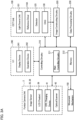
- the analyzing circuitry 234 includes the position specifying circuitry 2341 and the positional relationship acquiring circuitry 2342.
- the position specifying circuitry 2341 specifies the position of the predetermined site of the fundus Ef by analyzing the observation image acquired by the fundus camera unit 2. This process is sequentially performed, for example, on at least part of a plurality of image frames included in the observation image.
- the position specifying circuitry 2341 specifies the position of the predetermined site of the fundus Ef based on the pixel values (e.g., brightness values) included in the image frames.
- This position specifying process includes, for example, any known image processing such as thresholding on brightness values, binarization, edge detection, pattern matching, noise removal, morphological operation, and labeling.
- the position specifying circuitry 2341 can use thresholding to search for pixels each having a brightness value that exceeds a predetermined threshold.
- the position specifying circuitry 2341 can use binarization, edge detection, pattern matching, etc. to search for an image region of substantially elliptical shape.
- the position specifying circuitry 2341 can specify the position of the predetermined site of the fundus Ef, for example, based on any information on the specified image of the predetermined site such as its position, size, shape, etc.
- Sites specifiable (detectable) with such processing are the optic nerve head (its center, its center of gravity, its outer edge, a rectangle circumscribing the outer edge, etc.) and lesioned parts (their centers, centers of gravity, outer edges, rectangles circumscribing the outer edges, etc.), etc.
- the position specifying circuitry 2341 may specify the position of the predetermined site of the fundus Ef based on any information on these images such as their positions, relative positions, sizes, relative sizes, shapes, relative shapes, etc.
- Sites specifiable (detectable) with such processing are the optic nerve head (its center, its center of gravity, its outer edge, a rectangle circumscribing the outer edge, etc.) and a lesioned part (its centers, its center of gravity, its outer edge, a rectangle circumscribing the outer edges, etc.), etc.
- the positional relationship acquiring circuitry 2342 determines the positional relationship between the position of the predetermined site of the fundus Ef specified by the position specifying circuitry 2341 and the scan target area for OCT scanning.
- the scan target area may be set in an arbitrary manner.
- the scan target area may be an alignment target area for OCT scanning, part or all of the area on which OCT scanning is performed, or part or all of the area of an image frame of an observation image.
- the positional relationship acquiring circuitry 2342 can determine the deviation of the position of the predetermined site of the fundus Ef with respect to the scan target area.
- the deviation of the position of the predetermined site of the fundus Ef with respect to the scan target area is substantially equal to the deviation of the scan target area with respect to the position of the predetermined site of the fundus Ef.
- the positional relationship acquiring circuitry 2342 can determine the difference (e.g., the deviation vector) between the position of the predetermined site of the fundus Ef and a preset position in the scan target area. More specifically, the positional relationship acquiring circuitry 2342 determines any one of the followings: the deviation vector whose initial point is placed at the position of the predetermined site of the fundus Ef and whose terminal point is placed at the preset position in the scan target area; and the deviation vector whose initial point is placed at the preset position in the scan target area and whose terminal point is placed at the position of the predetermined site of the fundus Ef.
- the preset position in the scan target area may be set in an arbitrary manner.
- the preset position in the scan target area is set to any of the center of the scan target area, the position in which a plurality of scan lines intersect, and a position on the outer edge of the scan target area (e.g., apex position, middle point position of a side, etc.).
- the preset position in the scan target area may be a region having a certain size. For example, a certain region containing the center of the scan target area may be set as the preset position. Alternatively, the outer edge of the scan target area may be set as the preset position.
- the positional relationship acquiring circuitry 2342 may be configured to determine, for example, a deviation vector that is oriented along the shortest distance line between the position of the predetermined site of the fundus Ef and the certain region in the scan target area. In another example, the positional relationship acquiring circuitry 2342 may be configured to determine a deviation vector that connects the position of the predetermined site of the fundus Ef and a representative position (e.g., the center, the center of gravity, a position on the outer edge, etc.) in the certain region.
- a representative position e.g., the center, the center of gravity, a position on the outer edge, etc.
- the position of the predetermined site of the fundus Ef may be a region having a certain size.
- the positional relationship acquiring circuitry 2342 may be configured to determine a deviation vector based on a region whose center is the position specified by the position specifying circuitry 2341 (e.g., a circular region, a rectangular region, etc.) and a preset position in the scan target area. The size of that region is determined by, for example, the imaging magnification, the size of the scan target area, etc.
- Both the preset position in the scan target area and the position of the predetermined site of the fundus Ef may be regions of certain sizes. In such cases, the positional relationship acquiring circuitry 2342 can determine the positional relationship between the both regions.
- the positional relationship acquiring circuitry 2342 can determine whether or not the region of the predetermined site of the fundus Ef (e.g., the papillary center of gravity and the vicinity thereof) is located inside the outer edge of the scan target area. This determination is, for example, substantially the same processing as the determination regarding the magnitude of the difference between the position of the predetermined site of the fundus Ef (e.g., the papillary center of gravity) and the center of the scan target area.
- the deviation comparing circuitry 235 compares the deviation determined by the positional relationship acquiring circuitry 2342 with a predetermined threshold. This deviation is, for example, the magnitude of the deviation vector described above. The deviation comparing circuitry 235 determines, for example, whether or not the deviation determined by the positional relationship acquiring circuitry 2342 exceeds the predetermined threshold.
- the predetermined threshold may be set in an arbitrary manner.
- the predetermined threshold can be set to a small value in order to improve the precision of the fixation.
- the main controlling circuitry 211 performs automatic alignment and automatic focusing in the same manner as in a conventional case.
- the user may perform one or both of manual alignment and manual focusing. Thereby, the alignment and focusing with respect to the fundus Ef are completed.
- the positional relationship acquiring circuitry 2342 determines the positional relationship (deviation vector) between the position of the predetermined site of the fundus Ef specified by the position specifying circuitry 2341 and the scan target area for OCT scanning performed in the subsequent stage. Information obtained by the positional relationship acquiring circuitry 2342 (i.e., the deviation such as a deviation vector or its magnitude) is sent to the deviation comparing circuitry 235.
- the main controlling circuitry 211 displays a checking screen used for checking the fixation state, on the display device 241.
- the start timing of displaying the checking screen may be arbitrary.
- the display of the checking screen can be started at a timing prior to step S1 or at a timing in the period between steps S1 and S5.
- the main controlling circuitry 211 displays the observation image whose acquisition has started in step S2, on the checking screen. At this time, the observation image is displayed as a moving image.
- FIG. 5 An example of the checking screen is shown in FIG. 5 .
- the observation image G whose acquisition has been started in step S2 is displayed.
- the observation image G represents the image of the optic nerve head (optic nerve head image) Ga. Note that there are some cases in which the optic nerve head image Ga is not depicted in the observation image G due to fixation loss, etc.
- the checking screen 300 is provided with the capture button 310.
- the capture button 310 is a software key that receives an instruction for performing OCT imaging.
- the checking screen 300 displays a pointer (not shown in figures).
- the user can enter an instruction for OCT imaging by clicking the capture button 310 using the operation device 242.
- the display device 241 is a touch panel, the user can enter an instruction for OCT imaging by tapping the capture button 310.
- the main controlling circuitry 211 can display an image (a scan target area image) representing the scan target area for OCT scanning, on the checking screen 300.
- the scan target area image is generated by, for example, the main controlling circuitry 211.
- the scan target area image is displayed, for example, over the observation image G.
- the scan target area image T shown in FIG. 5 represents a target area of alignment for OCT scanning.
- the fixation deviation correction is performed so that the optic nerve head image Ga is located within the scan target area T.
- Such a scan target area is determined by the main controlling circuitry 211, for example, according to preset conditions such as the pattern and/or size of the OCT scan, the size of the observation image (e.g., observation magnification), and/or the target site of the OCT scanning (e.g., fixation position).
- the form of the scan target area image is not limited to this.
- a scan target area indicating part or all of the area on which OCT scanning is performed, or a scan target area indicating part or all of the area of an image frame of the observation image can be displayed together with the observation image G.
- the main controlling circuitry 211 can display on the checking screen 300 an image (referred to as an interested site image or an image of the site of interest) based on the position of the predetermined site (e.g., the optical nerve head, the papillary center of gravity) specified by the position specifying circuitry 2341 in step S4.
- the interested site image is displayed, for example, over the observation image G.
- the main controlling circuitry 211 can display, on the checking screen 300, an image (referred to as a positional relationship image) based on the positional relationship acquired by the positional relationship acquiring circuitry 2342 in step S5.
- the positional relationship image is displayed over the observation image G.
- the deviation comparing circuitry 235 compares the deviation acquired by the positional relationship acquiring circuitry 2342 in step S5 and a predetermined threshold.
- step S8: No When the deviation comparing circuitry 235 has determined that the deviation exceeds the threshold (deviation > threshold) by the comparison in step S7 (S8: No), the process proceeds to step S9. On the other hand, when the deviation comparing circuitry 235 has determined that the deviation is equal to or less than the threshold (deviation ⁇ threshold) (S8: Yes), the process proceeds to step S10.
- the main controlling circuitry 211 controls at least one of the scan area for OCT scanning and the display position of the fixation target.
- the control of the scan area is realized by control of the optical scanner 42.
- the control of the display position of the fixation target is realized by control of the LCD 39.
- the control target (the optical scanner 42 and/or the LCD 39) is determined in advance or determined during the processing.
- the main controlling circuitry 211 may be configured to control one of the optical scanner 42 and/or the LCD 39 at all times.
- the determination of the control target may be made, for example, with reference to arbitrary information as the followings: features and/or attributes of the subject; features and/or attributes of the subject's eye; features grasped from the observation image; and features grasped from an examination carried out in the past.
- the main controlling circuitry 211 shifts the scan area for OCT scanning to cancel out a deviation acquired by the positional relationship acquiring circuitry 2342.
- the main controlling circuitry 211 moves the position of the scan target area so that the predetermined site of the fundus Ef (e.g., the optic nerve head) is located inside the scan target area.
- the main controlling circuitry 211 can display the new scan target area T1 at a position different from that of the scan target area image T shown in FIG. 5 (i.e., at a position after the shift).
- the main controlling circuitry 211 changes the display position of the fixation target to cancel out a deviation acquired by the positional relationship acquiring circuitry 2342.
- the main controlling circuitry 211 moves the position of the subject's eye E so that the predetermined site of the fundus Ef (e.g., the optic nerve head) is placed inside the scan target area.
- the main controlling circuitry 211 can display the new observation image G1 depicting a region of the fundus Ef different from the observation image G shown in FIG. 5 (i.e., the new observation image G1 depicting a region after the shift).
- Such control of the optical scanner 42 and/or the LCD 39 regulates the relative position between the scan area for OCT imaging in the subsequent stage and the subject's eye E (the fundus Ef). More specifically, when controlling the optical scanner 42, the relative position is changed by shifting the scan area. On the other hand, when controlling the LCD 39, the relative position is changed by inducing the movement of the fundus Ef.
- step S8 After carrying out the control for the optical scanner 42 and/or the LCD 39, the process returns to step S4. Then, steps S4 to S8 are executed again. When the determination is "No” again in step S8, step S9 is executed again and then a routine of steps S4 to S8 is executed again. Such a series of processes is repeated until the determination in step S8 becomes "Yes".
- the ophthalmological apparatus can determine that an error occurs when a predetermined period of time passes from a predetermined timing such as the start of examination or the start of acquisition of the observation image.
- a predetermined timing such as the start of examination or the start of acquisition of the observation image.
- the user may determine an error. Such error determination is performed when an appropriate fixation state cannot be achieved easily.
- the main controlling circuitry 211 displays information indicating that an appropriate fixation state has been achieved, on the checking screen 300.
- the information may be predetermined text (character string) or image. For example, texts such as “fixation OK” or “ready for imaging” can be displayed. In addition, it is possible to display a predetermined image that allows the user to intuitively recognize that an appropriate fixation state has been reached.
- the ophthalmological apparatus 1 may be configured to continue displaying information indicating an inappropriate fixation state during the determination is "No" in step S8, and to switch the display content from the information indicating the inappropriate fixation state to information indicating an appropriate fixation state when the determination has become "Yes” in step S8.
- the user can perceive from the information displayed in step S10 that the appropriate fixation state has been reached. Alternatively, the user can perceive that the appropriate fixation state has been reached by referring to the observation image G.
- step S9 when the scan area has been shifted in step S9, the scan area after the shift is employed for OCT imaging.
- step S9 has been performed twice or more, that is, when the determination has been "No" twice or more in step S8, the scan area set in step S9 executed last is employed for OCT imaging.
- the three dimensional image constructing circuitry 231 can construct a three dimensional image. Further, the image projecting circuitry 232 can construct a front projection image from the three dimensional image. In addition, the registration processing circuitry 233 can perform registration between the front projection image and the observation image.
- the main controlling circuitry 211 controls the fundus camera unit 2 to perform photographing of the fundus Ef.
- photographing of the fundus Ef typically, color photography using visible light is performed.
- the fundus image (captured image, photographed image) obtained in step S12 is used for diagnostic imaging and image analysis together with or separately from the data obtained by the OCT imaging.
- the three dimensional image constructing circuitry 231 can construct a three dimensional image. Further, the image projecting circuitry 232 can construct a front projection image from the three dimensional image. In addition, the registration processing circuitry 233 can perform registration between the front projection image and the photographed image acquired in step S12. This is the end of the processing according to the present operation example.
- the ophthalmological apparatus of some embodiment examples includes a light beam projecting system, a fixation system, a photographing device, analyzing circuitry, and controlling circuitry.
- the light beam projecting system includes an optical scanner, and is configured to project the light beam onto the fundus of the subject's eye.
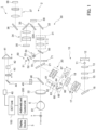
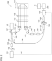
- the combination of elements included in the OCT unit 100 and optical elements forming the optical path for guiding the measurement light LS to the subject's eye E, functions as the light beam projecting system.
- the ophthalmological apparatus may further include a detector that detects return light of the light beam projected onto the fundus by the light beam projecting system.
- a detector is provided, for example, when the ophthalmological apparatus includes any of the functions of an OCT scanner, a scanning laser ophthalmoscope, an axial length measurement apparatus, a retinal characteristic measurement apparatus, and the like.
- the fixation system is configured to project fixation light onto the fundus.
- the photographing device is configured to capture a moving image of the fundus onto which the fixation light is being projected by the fixation system, to acquire a front observation image.
- the combination of the illumination optical system 10 and the photographing optical system 30 functions as the photographing device.
- the analyzing circuitry is configured to analyze the front observation image acquired by the photographing device to specify the position of the predetermined site of the fundus.
- the position specified by the analyzing circuitry is typically a position in the front observation image acquired by the photographing device, that is, a position in the observation target area.
- the analyzing circuitry 234 functions as the analyzing circuitry.
- the controlling circuitry is configured to control at least one of the fixation system and the optical scanner of the light beam projecting system based on the positional relationship between the position of the predetermined site specified by the analyzing circuitry and the projection target area of the light beam from the light beam projecting system.
- the main controlling circuitry 211 functions as the controlling circuitry.
- the controlling circuitry can change the projection target area of the light beam based on the positional relationship between the position of the predetermined site specified by the analyzing circuitry and the projection target area of the light beam from the light beam projecting system.
- the main controlling circuitry 211 changes the projection target area by controlling the optical scanner 42.
- the controlling circuitry can change the fixation position based on the positional relationship between the position of the predetermined site specified by the analyzing circuitry and the projection target area of the light beam from the light beam projecting system.
- the main controlling circuitry 211 changes the fixation position by controlling the LCD 39.
- the relative position between the area onto which the light beam is projected by the light beam projecting system and the subject's eye can be changed, based on the positional relationship between the predetermined site of the fundus (e.g., the papilla center of gravity) and the projection target area. Therefore, when fixation loss occurs (that is, when the positional relationship between the predetermined site of the fundus and the projection target area is not appropriate), the ophthalmological apparatus can regulate the fixation position of the subject's eye and/or the position of the area where the light beam is projected by the light beam projecting system, in order to eliminate the fixation loss. As a result, the ophthalmological apparatus can cope with the fixation loss in an appropriate manner.
- the predetermined site of the fundus e.g., the papilla center of gravity
- the controlling circuitry may be configured to display the front observation image acquired by the photographing device on a display device. Further, the controlling circuitry may be configured to display an image indicating the projection target area of the light beam from the light beam projecting system, over the front observation image.
- the display device 241 functions as the display device.
- the scan target area image T is displayed as the image indicating the projection target area.
- the user can observe the predetermined site of the fundus, grasp the projection target area of the light beam, and grasp the relative position between the predetermined site of the fundus and the projection target area.
- controlling circuitry may be configured to compare the deviation between the projection target area of the light beam and the position of the predetermined site of the fundus specified by the position specifying circuitry, with a predetermined threshold, and further execute control for at least one of the fixation system and the optical scanner of the light beam projecting system only when the deviation exceeds the predetermined threshold.
- the ophthalmological apparatus when the deviation of the projection target area with respect to the position of the predetermined site of the fundus is large, the ophthalmological apparatus can execute control for eliminating the fixation loss. In addition, when the deviation becomes sufficiently small, the ophthalmological apparatus can proceed to an examination (e.g., measurement, imaging).
- an examination e.g., measurement, imaging
Landscapes
- Health & Medical Sciences (AREA)
- Life Sciences & Earth Sciences (AREA)
- Biomedical Technology (AREA)
- Heart & Thoracic Surgery (AREA)
- Veterinary Medicine (AREA)
- Biophysics (AREA)
- Ophthalmology & Optometry (AREA)
- Engineering & Computer Science (AREA)
- Public Health (AREA)
- Physics & Mathematics (AREA)
- Medical Informatics (AREA)
- Molecular Biology (AREA)
- Surgery (AREA)
- Animal Behavior & Ethology (AREA)
- General Health & Medical Sciences (AREA)
- Nuclear Medicine, Radiotherapy & Molecular Imaging (AREA)
- Radiology & Medical Imaging (AREA)
- Eye Examination Apparatus (AREA)
Claims (9)
- Ophthalmologische Vorrichtung (1), die Folgendes umfasst:ein Lichtstrahlprojektionssystem (100), das einen optischen Scanner (42) aufweist und so konfiguriert ist, dass es einen Lichtstrahl auf einen Augenhintergrund eines Auges einer Person projiziert,ein Fixationssystem (39), das so konfiguriert ist, dass es Fixationslicht auf den Augenhintergrund projiziert,eine Fotografiereinrichtung (10, 30), die so konfiguriert ist, dass sie von dem Augenhintergrund, auf den das Fixationslicht projiziert wird, ein Bewegtbild aufnimmt und so ein Frontalbild erfasst,eine Analyseschaltung (234), die so konfiguriert ist, dass sie das Frontalbild analysiert, um eine Position einer vorgegebenen Stelle am Augenhintergrund zu bestimmen, wobei es sich bei der vorgegebenen Stelle um eine Makula oder/und um einen Sehnervenkopf handelt, undeine Steuerschaltung (211), die so konfiguriert ist, dass sie das Fixationssystem (39) oder/und den optischen Scanner (42) auf der Grundlage einer Positionsbeziehung zwischen der von den Analyseschaltungen (234) bestimmten Position der vorgegebenen Stelle und einem Projektionszielbereich für den Lichtstrahl aus dem Lichtstrahlprojektionssystem (100) steuert,wobei die Steuerschaltung (211) so konfiguriert ist, dass sie das Frontalbild auf einer Anzeigeeinrichtung (241) anzeigt und ein Bild, das den Projektionszielbereich für den Lichtstrahl angibt, ein Bild, das die Position der vorgegebenen Stelle angibt, und ein auf der Positionsbeziehung zwischen der Position der vorgegebenen Stelle und dem Projektionszielbereich basierendes Bild auf dem Frontalbild anzeigt.
- Ophthalmologische Vorrichtung nach Anspruch 1, wobei die Steuerschaltung (211) so konfiguriert ist, dass sie den optischen Scanner (42) so steuert, dass auf der Grundlage der Positionsbeziehung der Projektionszielbereich des Lichtstrahls geändert wird.
- Ophthalmologische Vorrichtung nach Anspruch 1 oder 2, wobei die Steuerschaltung (211) so konfiguriert ist, dass sie das Fixationssystem (39) so steuert, dass auf der Grundlage der Positionsbeziehung eine Fixationsposition geändert wird.
- Ophthalmologische Vorrichtung nach einem der Ansprüche 1 bis 3, wobei die Steuerschaltung (211) so konfiguriert ist, dass sie eine Abweichung der Position der vorgegebenen Stelle in Bezug auf den Projektionszielbereich für den Lichtstrahl mit einem vorgegebenen Schwellenwert vergleicht und das Fixationssystem (39) oder/und den optischen Scanner (42) nur dann ansteuert, wenn die Abweichung den vorgegebenen Schwellenwert übersteigt.
- Ophthalmologische Vorrichtung nach einem der Ansprüche 1 bis 4, wobei die Analyseschaltung (234) eine Positionsbeziehungserfassungsschaltung (2342) aufweist, die so konfiguriert ist, dass sie die Positionsbeziehung zwischen der Position der vorgegebenen Stelle und dem Projektionszielbereich ermittelt.
- Ophthalmologische Vorrichtung nach Anspruch 5, wobei die Positionsbeziehungserfassungsschaltung (2342) so konfiguriert ist, dass sie eine erste Abweichung der Position der vorgegebenen Stelle in Bezug auf den Projektionszielbereich oder eine zweite Abweichung des Projektionszielbereichs in Bezug auf die Position der vorgegebenen Stelle ermittelt.
- Ophthalmologische Vorrichtung nach Anspruch 6, wobei die Positionsbeziehungserfassungsschaltung (2342) so konfiguriert ist, dass sie einen ersten Abweichungsvektor, dessen Anfangspunkt an einer voreingestellten Position in dem Projektionszielbereich und dessen Endpunkt an einer Position der vorgegebenen Stelle angeordnet ist, als erste Abweichung oder einen zweiten Abweichungsvektor, dessen Anfangspunkt an einer Position der vorgegebenen Stelle und dessen Endpunkt an einer voreingestellten Position in dem Projektionszielbereich angeordnet ist, als zweiten Abweichungsvektor ermittelt.
- Ophthalmologische Vorrichtung nach Anspruch 7, wobei es sich bei der voreingestellten Position im Projektionszielbereich um einen Mittelpunkt des Projektionszielbereichs, eine Position, an der sich mehrere Scanlinien schneiden, oder eine Position an einem Außenrand des Projektionszielbereichs handelt.
- Ophthalmologische Vorrichtung nach Anspruch 7, wobei es sich bei der voreingestellten Position im Projektionszielbereich und/oder bei der Position der vorgegebenen Stelle um eine Region mit einer Größe handelt.
Applications Claiming Priority (2)
| Application Number | Priority Date | Filing Date | Title |
|---|---|---|---|
| JP2017009515A JP2018117693A (ja) | 2017-01-23 | 2017-01-23 | 眼科装置 |
| PCT/JP2017/044184 WO2018135175A1 (ja) | 2017-01-23 | 2017-12-08 | 眼科装置 |
Publications (3)
| Publication Number | Publication Date |
|---|---|
| EP3571978A1 EP3571978A1 (de) | 2019-11-27 |
| EP3571978A4 EP3571978A4 (de) | 2020-08-19 |
| EP3571978B1 true EP3571978B1 (de) | 2025-03-26 |
Family
ID=62908104
Family Applications (1)
| Application Number | Title | Priority Date | Filing Date |
|---|---|---|---|
| EP17892116.9A Active EP3571978B1 (de) | 2017-01-23 | 2017-12-08 | Ophthalmologische vorrichtung |
Country Status (4)
| Country | Link |
|---|---|
| US (1) | US11122973B2 (de) |
| EP (1) | EP3571978B1 (de) |
| JP (1) | JP2018117693A (de) |
| WO (1) | WO2018135175A1 (de) |
Families Citing this family (5)
| Publication number | Priority date | Publication date | Assignee | Title |
|---|---|---|---|---|
| EP3760967A3 (de) | 2019-07-02 | 2021-04-07 | Topcon Corporation | Verfahren zur verarbeitung von daten der optischen kohärenztomografie (oct) |
| JP7409793B2 (ja) * | 2019-07-02 | 2024-01-09 | 株式会社トプコン | 光コヒーレンストモグラフィ(oct)装置の作動方法、octデータ処理装置の作動方法、oct装置、octデータ処理装置 |
| WO2021074960A1 (ja) * | 2019-10-15 | 2021-04-22 | 株式会社ニコン | 画像処理方法、画像処理装置、及び画像処理プログラム |
| JP7476693B2 (ja) * | 2020-07-03 | 2024-05-01 | 株式会社ニデック | 眼底撮影装置 |
| JP7590202B2 (ja) * | 2021-02-05 | 2024-11-26 | 株式会社トプコン | 医療評価装置 |
Family Cites Families (11)
| Publication number | Priority date | Publication date | Assignee | Title |
|---|---|---|---|---|
| DE4326716B4 (de) * | 1992-08-04 | 2005-03-03 | Kabushiki Kaisha Topcon | Anordnung zur Verarbeitung eines ophthalmologischen Bildes |
| JP5138977B2 (ja) * | 2007-05-24 | 2013-02-06 | 株式会社トプコン | 光画像計測装置 |
| JP2009072513A (ja) * | 2007-09-25 | 2009-04-09 | Topcon Corp | 眼科装置 |
| US8672480B2 (en) | 2009-09-30 | 2014-03-18 | Nidek Co., Ltd. | Ophthalmic photographing apparatus |
| US8419186B2 (en) | 2009-09-30 | 2013-04-16 | Nidek Co., Ltd. | Fundus observation apparatus |
| JP5981213B2 (ja) | 2012-02-28 | 2016-08-31 | 株式会社トプコン | 眼底観察装置 |
| US9295387B2 (en) * | 2013-04-03 | 2016-03-29 | Kabushiki Kaisha Topcon | Ophthalmologic apparatus |
| JP6438216B2 (ja) * | 2014-05-22 | 2018-12-12 | キヤノン株式会社 | 画像生成装置および画像生成方法 |
| JP6518044B2 (ja) * | 2014-07-18 | 2019-05-22 | 株式会社トプコン | 視機能検査装置および視機能検査システム |
| JP6388440B2 (ja) * | 2014-11-26 | 2018-09-12 | 株式会社トプコン | 眼科装置 |
| JP2016158721A (ja) | 2015-02-27 | 2016-09-05 | 株式会社ニデック | 眼科装置 |
-
2017
- 2017-01-23 JP JP2017009515A patent/JP2018117693A/ja active Pending
- 2017-12-08 US US16/470,989 patent/US11122973B2/en active Active
- 2017-12-08 WO PCT/JP2017/044184 patent/WO2018135175A1/ja not_active Ceased
- 2017-12-08 EP EP17892116.9A patent/EP3571978B1/de active Active
Also Published As
| Publication number | Publication date |
|---|---|
| US20190365223A1 (en) | 2019-12-05 |
| US11122973B2 (en) | 2021-09-21 |
| JP2018117693A (ja) | 2018-08-02 |
| EP3571978A4 (de) | 2020-08-19 |
| EP3571978A1 (de) | 2019-11-27 |
| WO2018135175A1 (ja) | 2018-07-26 |
Similar Documents
| Publication | Publication Date | Title |
|---|---|---|
| US10702145B2 (en) | Ophthalmologic apparatus | |
| US10849499B2 (en) | Ophthalmologic apparatus and method of controlling the same | |
| JP6899632B2 (ja) | 眼科撮影装置 | |
| EP3461397A1 (de) | Ophthalmische vorrichtung | |
| US10786153B2 (en) | Ophthalmologic imaging apparatus | |
| US12096983B2 (en) | Ophthalmic imaging apparatus, controlling method of the same, and recording medium | |
| EP3571978B1 (de) | Ophthalmologische vorrichtung | |
| EP3607871B1 (de) | Ophthalmologische vorrichtung und verfahren zur steuerung davon | |
| US11291368B2 (en) | Ophthalmologic apparatus and method of controlling the same | |
| JP2023080218A (ja) | 眼科装置 | |
| US11571123B2 (en) | Ophthalmologic apparatus and method of controlling the same | |
| JP2019170710A (ja) | 眼科装置 | |
| US11202566B2 (en) | Ophthalmologic apparatus and method of controlling the same | |
| JP7116572B2 (ja) | 眼科装置、及び眼科情報処理プログラム | |
| JP7201855B2 (ja) | 眼科装置、及び眼科情報処理プログラム | |
| JP7219312B2 (ja) | 眼科装置 | |
| JP7154260B2 (ja) | 眼科装置 | |
| JP7244211B2 (ja) | 眼科装置、及び眼科装置の制御方法 |
Legal Events
| Date | Code | Title | Description |
|---|---|---|---|
| STAA | Information on the status of an ep patent application or granted ep patent |
Free format text: STATUS: THE INTERNATIONAL PUBLICATION HAS BEEN MADE |
|
| PUAI | Public reference made under article 153(3) epc to a published international application that has entered the european phase |
Free format text: ORIGINAL CODE: 0009012 |
|
| STAA | Information on the status of an ep patent application or granted ep patent |
Free format text: STATUS: REQUEST FOR EXAMINATION WAS MADE |
|
| 17P | Request for examination filed |
Effective date: 20190814 |
|
| AK | Designated contracting states |
Kind code of ref document: A1 Designated state(s): AL AT BE BG CH CY CZ DE DK EE ES FI FR GB GR HR HU IE IS IT LI LT LU LV MC MK MT NL NO PL PT RO RS SE SI SK SM TR |
|
| AX | Request for extension of the european patent |
Extension state: BA ME |
|
| DAV | Request for validation of the european patent (deleted) | ||
| DAX | Request for extension of the european patent (deleted) | ||
| A4 | Supplementary search report drawn up and despatched |
Effective date: 20200720 |
|
| RIC1 | Information provided on ipc code assigned before grant |
Ipc: A61B 3/10 20060101AFI20200714BHEP |
|
| STAA | Information on the status of an ep patent application or granted ep patent |
Free format text: STATUS: EXAMINATION IS IN PROGRESS |
|
| 17Q | First examination report despatched |
Effective date: 20221028 |
|
| GRAP | Despatch of communication of intention to grant a patent |
Free format text: ORIGINAL CODE: EPIDOSNIGR1 |
|
| STAA | Information on the status of an ep patent application or granted ep patent |
Free format text: STATUS: GRANT OF PATENT IS INTENDED |
|
| INTG | Intention to grant announced |
Effective date: 20241106 |
|
| GRAS | Grant fee paid |
Free format text: ORIGINAL CODE: EPIDOSNIGR3 |
|
| GRAA | (expected) grant |
Free format text: ORIGINAL CODE: 0009210 |
|
| STAA | Information on the status of an ep patent application or granted ep patent |
Free format text: STATUS: THE PATENT HAS BEEN GRANTED |
|
| AK | Designated contracting states |
Kind code of ref document: B1 Designated state(s): AL AT BE BG CH CY CZ DE DK EE ES FI FR GB GR HR HU IE IS IT LI LT LU LV MC MK MT NL NO PL PT RO RS SE SI SK SM TR |
|
| REG | Reference to a national code |
Ref country code: GB Ref legal event code: FG4D |
|
| REG | Reference to a national code |
Ref country code: CH Ref legal event code: EP |
|
| REG | Reference to a national code |
Ref country code: DE Ref legal event code: R096 Ref document number: 602017088591 Country of ref document: DE |
|
| REG | Reference to a national code |
Ref country code: IE Ref legal event code: FG4D |
|
| PG25 | Lapsed in a contracting state [announced via postgrant information from national office to epo] |
Ref country code: RS Free format text: LAPSE BECAUSE OF FAILURE TO SUBMIT A TRANSLATION OF THE DESCRIPTION OR TO PAY THE FEE WITHIN THE PRESCRIBED TIME-LIMIT Effective date: 20250626 |
|
| PG25 | Lapsed in a contracting state [announced via postgrant information from national office to epo] |
Ref country code: FI Free format text: LAPSE BECAUSE OF FAILURE TO SUBMIT A TRANSLATION OF THE DESCRIPTION OR TO PAY THE FEE WITHIN THE PRESCRIBED TIME-LIMIT Effective date: 20250326 |
|
| REG | Reference to a national code |
Ref country code: LT Ref legal event code: MG9D |
|
| PG25 | Lapsed in a contracting state [announced via postgrant information from national office to epo] |
Ref country code: NO Free format text: LAPSE BECAUSE OF FAILURE TO SUBMIT A TRANSLATION OF THE DESCRIPTION OR TO PAY THE FEE WITHIN THE PRESCRIBED TIME-LIMIT Effective date: 20250626 |
|
| PG25 | Lapsed in a contracting state [announced via postgrant information from national office to epo] |
Ref country code: HR Free format text: LAPSE BECAUSE OF FAILURE TO SUBMIT A TRANSLATION OF THE DESCRIPTION OR TO PAY THE FEE WITHIN THE PRESCRIBED TIME-LIMIT Effective date: 20250326 |
|
| PG25 | Lapsed in a contracting state [announced via postgrant information from national office to epo] |
Ref country code: LV Free format text: LAPSE BECAUSE OF FAILURE TO SUBMIT A TRANSLATION OF THE DESCRIPTION OR TO PAY THE FEE WITHIN THE PRESCRIBED TIME-LIMIT Effective date: 20250326 |
|
| PG25 | Lapsed in a contracting state [announced via postgrant information from national office to epo] |
Ref country code: GR Free format text: LAPSE BECAUSE OF FAILURE TO SUBMIT A TRANSLATION OF THE DESCRIPTION OR TO PAY THE FEE WITHIN THE PRESCRIBED TIME-LIMIT Effective date: 20250627 Ref country code: BG Free format text: LAPSE BECAUSE OF FAILURE TO SUBMIT A TRANSLATION OF THE DESCRIPTION OR TO PAY THE FEE WITHIN THE PRESCRIBED TIME-LIMIT Effective date: 20250326 |
|
| REG | Reference to a national code |
Ref country code: NL Ref legal event code: MP Effective date: 20250326 |
|
| PG25 | Lapsed in a contracting state [announced via postgrant information from national office to epo] |
Ref country code: NL Free format text: LAPSE BECAUSE OF FAILURE TO SUBMIT A TRANSLATION OF THE DESCRIPTION OR TO PAY THE FEE WITHIN THE PRESCRIBED TIME-LIMIT Effective date: 20250326 |
|
| PG25 | Lapsed in a contracting state [announced via postgrant information from national office to epo] |
Ref country code: SE Free format text: LAPSE BECAUSE OF FAILURE TO SUBMIT A TRANSLATION OF THE DESCRIPTION OR TO PAY THE FEE WITHIN THE PRESCRIBED TIME-LIMIT Effective date: 20250326 |
|
| REG | Reference to a national code |
Ref country code: AT Ref legal event code: MK05 Ref document number: 1778201 Country of ref document: AT Kind code of ref document: T Effective date: 20250326 |
|
| PG25 | Lapsed in a contracting state [announced via postgrant information from national office to epo] |
Ref country code: SM Free format text: LAPSE BECAUSE OF FAILURE TO SUBMIT A TRANSLATION OF THE DESCRIPTION OR TO PAY THE FEE WITHIN THE PRESCRIBED TIME-LIMIT Effective date: 20250326 |
|
| PG25 | Lapsed in a contracting state [announced via postgrant information from national office to epo] |
Ref country code: PT Free format text: LAPSE BECAUSE OF FAILURE TO SUBMIT A TRANSLATION OF THE DESCRIPTION OR TO PAY THE FEE WITHIN THE PRESCRIBED TIME-LIMIT Effective date: 20250728 Ref country code: ES Free format text: LAPSE BECAUSE OF FAILURE TO SUBMIT A TRANSLATION OF THE DESCRIPTION OR TO PAY THE FEE WITHIN THE PRESCRIBED TIME-LIMIT Effective date: 20250326 |
|
| PG25 | Lapsed in a contracting state [announced via postgrant information from national office to epo] |
Ref country code: PL Free format text: LAPSE BECAUSE OF FAILURE TO SUBMIT A TRANSLATION OF THE DESCRIPTION OR TO PAY THE FEE WITHIN THE PRESCRIBED TIME-LIMIT Effective date: 20250326 Ref country code: IT Free format text: LAPSE BECAUSE OF FAILURE TO SUBMIT A TRANSLATION OF THE DESCRIPTION OR TO PAY THE FEE WITHIN THE PRESCRIBED TIME-LIMIT Effective date: 20250326 |
|
| PG25 | Lapsed in a contracting state [announced via postgrant information from national office to epo] |
Ref country code: AT Free format text: LAPSE BECAUSE OF FAILURE TO SUBMIT A TRANSLATION OF THE DESCRIPTION OR TO PAY THE FEE WITHIN THE PRESCRIBED TIME-LIMIT Effective date: 20250326 |
|
| PG25 | Lapsed in a contracting state [announced via postgrant information from national office to epo] |
Ref country code: EE Free format text: LAPSE BECAUSE OF FAILURE TO SUBMIT A TRANSLATION OF THE DESCRIPTION OR TO PAY THE FEE WITHIN THE PRESCRIBED TIME-LIMIT Effective date: 20250326 |
|
| PG25 | Lapsed in a contracting state [announced via postgrant information from national office to epo] |
Ref country code: RO Free format text: LAPSE BECAUSE OF FAILURE TO SUBMIT A TRANSLATION OF THE DESCRIPTION OR TO PAY THE FEE WITHIN THE PRESCRIBED TIME-LIMIT Effective date: 20250326 |
|
| PG25 | Lapsed in a contracting state [announced via postgrant information from national office to epo] |
Ref country code: SK Free format text: LAPSE BECAUSE OF FAILURE TO SUBMIT A TRANSLATION OF THE DESCRIPTION OR TO PAY THE FEE WITHIN THE PRESCRIBED TIME-LIMIT Effective date: 20250326 |
|
| PG25 | Lapsed in a contracting state [announced via postgrant information from national office to epo] |
Ref country code: IS Free format text: LAPSE BECAUSE OF FAILURE TO SUBMIT A TRANSLATION OF THE DESCRIPTION OR TO PAY THE FEE WITHIN THE PRESCRIBED TIME-LIMIT Effective date: 20250726 |
|
| REG | Reference to a national code |
Ref country code: DE Ref legal event code: R097 Ref document number: 602017088591 Country of ref document: DE |
|
| PGFP | Annual fee paid to national office [announced via postgrant information from national office to epo] |
Ref country code: DE Payment date: 20251028 Year of fee payment: 9 |
|
| PG25 | Lapsed in a contracting state [announced via postgrant information from national office to epo] |
Ref country code: DK Free format text: LAPSE BECAUSE OF FAILURE TO SUBMIT A TRANSLATION OF THE DESCRIPTION OR TO PAY THE FEE WITHIN THE PRESCRIBED TIME-LIMIT Effective date: 20250326 |
|
| PGFP | Annual fee paid to national office [announced via postgrant information from national office to epo] |
Ref country code: FR Payment date: 20251110 Year of fee payment: 9 |
|
| PG25 | Lapsed in a contracting state [announced via postgrant information from national office to epo] |
Ref country code: CZ Free format text: LAPSE BECAUSE OF FAILURE TO SUBMIT A TRANSLATION OF THE DESCRIPTION OR TO PAY THE FEE WITHIN THE PRESCRIBED TIME-LIMIT Effective date: 20250326 |
|
| PLBE | No opposition filed within time limit |
Free format text: ORIGINAL CODE: 0009261 |
|
| STAA | Information on the status of an ep patent application or granted ep patent |
Free format text: STATUS: NO OPPOSITION FILED WITHIN TIME LIMIT |
|
| REG | Reference to a national code |
Ref country code: CH Ref legal event code: L10 Free format text: ST27 STATUS EVENT CODE: U-0-0-L10-L00 (AS PROVIDED BY THE NATIONAL OFFICE) Effective date: 20260211 |
|
| 26N | No opposition filed |
Effective date: 20260105 |