EP3571129B1 - Verschluss für behälter mit informations- oder fälschungssicherungsfähigkeiten - Google Patents
Verschluss für behälter mit informations- oder fälschungssicherungsfähigkeiten Download PDFInfo
- Publication number
- EP3571129B1 EP3571129B1 EP18741836.3A EP18741836A EP3571129B1 EP 3571129 B1 EP3571129 B1 EP 3571129B1 EP 18741836 A EP18741836 A EP 18741836A EP 3571129 B1 EP3571129 B1 EP 3571129B1
- Authority
- EP
- European Patent Office
- Prior art keywords
- closure
- cap
- disc
- container
- tag
- Prior art date
- Legal status (The legal status is an assumption and is not a legal conclusion. Google has not performed a legal analysis and makes no representation as to the accuracy of the status listed.)
- Active
Links
Images




Classifications
-
- B—PERFORMING OPERATIONS; TRANSPORTING
- B65—CONVEYING; PACKING; STORING; HANDLING THIN OR FILAMENTARY MATERIAL
- B65D—CONTAINERS FOR STORAGE OR TRANSPORT OF ARTICLES OR MATERIALS, e.g. BAGS, BARRELS, BOTTLES, BOXES, CANS, CARTONS, CRATES, DRUMS, JARS, TANKS, HOPPERS, FORWARDING CONTAINERS; ACCESSORIES, CLOSURES, OR FITTINGS THEREFOR; PACKAGING ELEMENTS; PACKAGES
- B65D41/00—Caps, e.g. crown caps or crown seals, i.e. members having parts arranged for engagement with the external periphery of a neck or wall defining a pouring opening or discharge aperture; Protective cap-like covers for closure members, e.g. decorative covers of metal foil or paper
- B65D41/32—Caps or cap-like covers with lines of weakness, tearing-strips, tags, or like opening or removal devices, e.g. to facilitate formation of pouring openings
-
- B—PERFORMING OPERATIONS; TRANSPORTING
- B65—CONVEYING; PACKING; STORING; HANDLING THIN OR FILAMENTARY MATERIAL
- B65D—CONTAINERS FOR STORAGE OR TRANSPORT OF ARTICLES OR MATERIALS, e.g. BAGS, BARRELS, BOTTLES, BOXES, CANS, CARTONS, CRATES, DRUMS, JARS, TANKS, HOPPERS, FORWARDING CONTAINERS; ACCESSORIES, CLOSURES, OR FITTINGS THEREFOR; PACKAGING ELEMENTS; PACKAGES
- B65D55/00—Accessories for container closures not otherwise provided for
- B65D55/02—Locking devices; Means for discouraging or indicating unauthorised opening or removal of closure
- B65D55/028—Locking devices; Means for discouraging or indicating unauthorised opening or removal of closure initial opening or unauthorised access being indicated by the presence or absence of an audible or electrical signal
-
- B—PERFORMING OPERATIONS; TRANSPORTING
- B65—CONVEYING; PACKING; STORING; HANDLING THIN OR FILAMENTARY MATERIAL
- B65D—CONTAINERS FOR STORAGE OR TRANSPORT OF ARTICLES OR MATERIALS, e.g. BAGS, BARRELS, BOTTLES, BOXES, CANS, CARTONS, CRATES, DRUMS, JARS, TANKS, HOPPERS, FORWARDING CONTAINERS; ACCESSORIES, CLOSURES, OR FITTINGS THEREFOR; PACKAGING ELEMENTS; PACKAGES
- B65D41/00—Caps, e.g. crown caps or crown seals, i.e. members having parts arranged for engagement with the external periphery of a neck or wall defining a pouring opening or discharge aperture; Protective cap-like covers for closure members, e.g. decorative covers of metal foil or paper
- B65D41/02—Caps or cap-like covers without lines of weakness, tearing strips, tags, or like opening or removal devices
- B65D41/04—Threaded or like caps or cap-like covers secured by rotation
- B65D41/0435—Threaded or like caps or cap-like covers secured by rotation with separate sealing elements
- B65D41/045—Discs
-
- B—PERFORMING OPERATIONS; TRANSPORTING
- B65—CONVEYING; PACKING; STORING; HANDLING THIN OR FILAMENTARY MATERIAL
- B65D—CONTAINERS FOR STORAGE OR TRANSPORT OF ARTICLES OR MATERIALS, e.g. BAGS, BARRELS, BOTTLES, BOXES, CANS, CARTONS, CRATES, DRUMS, JARS, TANKS, HOPPERS, FORWARDING CONTAINERS; ACCESSORIES, CLOSURES, OR FITTINGS THEREFOR; PACKAGING ELEMENTS; PACKAGES
- B65D41/00—Caps, e.g. crown caps or crown seals, i.e. members having parts arranged for engagement with the external periphery of a neck or wall defining a pouring opening or discharge aperture; Protective cap-like covers for closure members, e.g. decorative covers of metal foil or paper
- B65D41/32—Caps or cap-like covers with lines of weakness, tearing-strips, tags, or like opening or removal devices, e.g. to facilitate formation of pouring openings
- B65D41/34—Threaded or like caps or cap-like covers provided with tamper elements formed in, or attached to, the closure skirt
-
- B—PERFORMING OPERATIONS; TRANSPORTING
- B65—CONVEYING; PACKING; STORING; HANDLING THIN OR FILAMENTARY MATERIAL
- B65D—CONTAINERS FOR STORAGE OR TRANSPORT OF ARTICLES OR MATERIALS, e.g. BAGS, BARRELS, BOTTLES, BOXES, CANS, CARTONS, CRATES, DRUMS, JARS, TANKS, HOPPERS, FORWARDING CONTAINERS; ACCESSORIES, CLOSURES, OR FITTINGS THEREFOR; PACKAGING ELEMENTS; PACKAGES
- B65D50/00—Closures with means for discouraging unauthorised opening or removal thereof, with or without indicating means, e.g. child-proof closures
- B65D50/02—Closures with means for discouraging unauthorised opening or removal thereof, with or without indicating means, e.g. child-proof closures openable or removable by the combination of plural actions
- B65D50/04—Closures with means for discouraging unauthorised opening or removal thereof, with or without indicating means, e.g. child-proof closures openable or removable by the combination of plural actions requiring the combination of simultaneous actions, e.g. depressing and turning, lifting and turning, maintaining a part and turning another one
-
- B—PERFORMING OPERATIONS; TRANSPORTING
- B65—CONVEYING; PACKING; STORING; HANDLING THIN OR FILAMENTARY MATERIAL
- B65D—CONTAINERS FOR STORAGE OR TRANSPORT OF ARTICLES OR MATERIALS, e.g. BAGS, BARRELS, BOTTLES, BOXES, CANS, CARTONS, CRATES, DRUMS, JARS, TANKS, HOPPERS, FORWARDING CONTAINERS; ACCESSORIES, CLOSURES, OR FITTINGS THEREFOR; PACKAGING ELEMENTS; PACKAGES
- B65D55/00—Accessories for container closures not otherwise provided for
- B65D55/02—Locking devices; Means for discouraging or indicating unauthorised opening or removal of closure
-
- B—PERFORMING OPERATIONS; TRANSPORTING
- B65—CONVEYING; PACKING; STORING; HANDLING THIN OR FILAMENTARY MATERIAL
- B65D—CONTAINERS FOR STORAGE OR TRANSPORT OF ARTICLES OR MATERIALS, e.g. BAGS, BARRELS, BOTTLES, BOXES, CANS, CARTONS, CRATES, DRUMS, JARS, TANKS, HOPPERS, FORWARDING CONTAINERS; ACCESSORIES, CLOSURES, OR FITTINGS THEREFOR; PACKAGING ELEMENTS; PACKAGES
- B65D55/00—Accessories for container closures not otherwise provided for
- B65D55/02—Locking devices; Means for discouraging or indicating unauthorised opening or removal of closure
- B65D55/024—Closures in which a part has to be ruptured to gain access to the contents
-
- B—PERFORMING OPERATIONS; TRANSPORTING
- B65—CONVEYING; PACKING; STORING; HANDLING THIN OR FILAMENTARY MATERIAL
- B65D—CONTAINERS FOR STORAGE OR TRANSPORT OF ARTICLES OR MATERIALS, e.g. BAGS, BARRELS, BOTTLES, BOXES, CANS, CARTONS, CRATES, DRUMS, JARS, TANKS, HOPPERS, FORWARDING CONTAINERS; ACCESSORIES, CLOSURES, OR FITTINGS THEREFOR; PACKAGING ELEMENTS; PACKAGES
- B65D55/00—Accessories for container closures not otherwise provided for
- B65D55/02—Locking devices; Means for discouraging or indicating unauthorised opening or removal of closure
- B65D55/026—Locking devices; Means for discouraging or indicating unauthorised opening or removal of closure initial opening or unauthorised access being indicated by a visual change using indicators other than tearable means, e.g. change of colour, pattern or opacity
-
- B—PERFORMING OPERATIONS; TRANSPORTING
- B65—CONVEYING; PACKING; STORING; HANDLING THIN OR FILAMENTARY MATERIAL
- B65D—CONTAINERS FOR STORAGE OR TRANSPORT OF ARTICLES OR MATERIALS, e.g. BAGS, BARRELS, BOTTLES, BOXES, CANS, CARTONS, CRATES, DRUMS, JARS, TANKS, HOPPERS, FORWARDING CONTAINERS; ACCESSORIES, CLOSURES, OR FITTINGS THEREFOR; PACKAGING ELEMENTS; PACKAGES
- B65D55/00—Accessories for container closures not otherwise provided for
- B65D55/02—Locking devices; Means for discouraging or indicating unauthorised opening or removal of closure
- B65D55/12—Devices or means with relatively-moving parts co-operating with abutments on bottle or jar
-
- G—PHYSICS
- G06—COMPUTING OR CALCULATING; COUNTING
- G06K—GRAPHICAL DATA READING; PRESENTATION OF DATA; RECORD CARRIERS; HANDLING RECORD CARRIERS
- G06K19/00—Record carriers for use with machines and with at least a part designed to carry digital markings
- G06K19/06—Record carriers for use with machines and with at least a part designed to carry digital markings characterised by the kind of the digital marking, e.g. shape, nature, code
- G06K19/067—Record carriers with conductive marks, printed circuits or semiconductor circuit elements, e.g. credit or identity cards also with resonating or responding marks without active components
- G06K19/07—Record carriers with conductive marks, printed circuits or semiconductor circuit elements, e.g. credit or identity cards also with resonating or responding marks without active components with integrated circuit chips
- G06K19/0701—Record carriers with conductive marks, printed circuits or semiconductor circuit elements, e.g. credit or identity cards also with resonating or responding marks without active components with integrated circuit chips at least one of the integrated circuit chips comprising an arrangement for power management
- G06K19/0707—Record carriers with conductive marks, printed circuits or semiconductor circuit elements, e.g. credit or identity cards also with resonating or responding marks without active components with integrated circuit chips at least one of the integrated circuit chips comprising an arrangement for power management the arrangement being capable of collecting energy from external energy sources, e.g. thermocouples, vibration, electromagnetic radiation
-
- G—PHYSICS
- G06—COMPUTING OR CALCULATING; COUNTING
- G06K—GRAPHICAL DATA READING; PRESENTATION OF DATA; RECORD CARRIERS; HANDLING RECORD CARRIERS
- G06K19/00—Record carriers for use with machines and with at least a part designed to carry digital markings
- G06K19/06—Record carriers for use with machines and with at least a part designed to carry digital markings characterised by the kind of the digital marking, e.g. shape, nature, code
- G06K19/067—Record carriers with conductive marks, printed circuits or semiconductor circuit elements, e.g. credit or identity cards also with resonating or responding marks without active components
- G06K19/07—Record carriers with conductive marks, printed circuits or semiconductor circuit elements, e.g. credit or identity cards also with resonating or responding marks without active components with integrated circuit chips
- G06K19/0723—Record carriers with conductive marks, printed circuits or semiconductor circuit elements, e.g. credit or identity cards also with resonating or responding marks without active components with integrated circuit chips the record carrier comprising an arrangement for non-contact communication, e.g. wireless communication circuits on transponder cards, non-contact smart cards or RFIDs
-
- G—PHYSICS
- G06—COMPUTING OR CALCULATING; COUNTING
- G06K—GRAPHICAL DATA READING; PRESENTATION OF DATA; RECORD CARRIERS; HANDLING RECORD CARRIERS
- G06K19/00—Record carriers for use with machines and with at least a part designed to carry digital markings
- G06K19/06—Record carriers for use with machines and with at least a part designed to carry digital markings characterised by the kind of the digital marking, e.g. shape, nature, code
- G06K19/08—Record carriers for use with machines and with at least a part designed to carry digital markings characterised by the kind of the digital marking, e.g. shape, nature, code using markings of different kinds or more than one marking of the same kind in the same record carrier, e.g. one marking being sensed by optical and the other by magnetic means
- G06K19/083—Constructional details
- G06K19/086—Constructional details with markings consisting of randomly placed or oriented elements, the randomness of the elements being useable for generating a unique identifying signature of the record carrier, e.g. randomly placed magnetic fibers or magnetic particles in the body of a credit card
-
- H—ELECTRICITY
- H04—ELECTRIC COMMUNICATION TECHNIQUE
- H04W—WIRELESS COMMUNICATION NETWORKS
- H04W4/00—Services specially adapted for wireless communication networks; Facilities therefor
- H04W4/80—Services using short range communication, e.g. near-field communication [NFC], radio-frequency identification [RFID] or low energy communication
-
- B—PERFORMING OPERATIONS; TRANSPORTING
- B65—CONVEYING; PACKING; STORING; HANDLING THIN OR FILAMENTARY MATERIAL
- B65D—CONTAINERS FOR STORAGE OR TRANSPORT OF ARTICLES OR MATERIALS, e.g. BAGS, BARRELS, BOTTLES, BOXES, CANS, CARTONS, CRATES, DRUMS, JARS, TANKS, HOPPERS, FORWARDING CONTAINERS; ACCESSORIES, CLOSURES, OR FITTINGS THEREFOR; PACKAGING ELEMENTS; PACKAGES
- B65D2203/00—Decoration means, markings, information elements, contents indicators
- B65D2203/06—Arrangements on packages concerning bar-codes
-
- B—PERFORMING OPERATIONS; TRANSPORTING
- B65—CONVEYING; PACKING; STORING; HANDLING THIN OR FILAMENTARY MATERIAL
- B65D—CONTAINERS FOR STORAGE OR TRANSPORT OF ARTICLES OR MATERIALS, e.g. BAGS, BARRELS, BOTTLES, BOXES, CANS, CARTONS, CRATES, DRUMS, JARS, TANKS, HOPPERS, FORWARDING CONTAINERS; ACCESSORIES, CLOSURES, OR FITTINGS THEREFOR; PACKAGING ELEMENTS; PACKAGES
- B65D2203/00—Decoration means, markings, information elements, contents indicators
- B65D2203/10—Transponders
-
- B—PERFORMING OPERATIONS; TRANSPORTING
- B65—CONVEYING; PACKING; STORING; HANDLING THIN OR FILAMENTARY MATERIAL
- B65D—CONTAINERS FOR STORAGE OR TRANSPORT OF ARTICLES OR MATERIALS, e.g. BAGS, BARRELS, BOTTLES, BOXES, CANS, CARTONS, CRATES, DRUMS, JARS, TANKS, HOPPERS, FORWARDING CONTAINERS; ACCESSORIES, CLOSURES, OR FITTINGS THEREFOR; PACKAGING ELEMENTS; PACKAGES
- B65D2203/00—Decoration means, markings, information elements, contents indicators
- B65D2203/12—Audible, olfactory or visual signalling means
-
- B—PERFORMING OPERATIONS; TRANSPORTING
- B65—CONVEYING; PACKING; STORING; HANDLING THIN OR FILAMENTARY MATERIAL
- B65D—CONTAINERS FOR STORAGE OR TRANSPORT OF ARTICLES OR MATERIALS, e.g. BAGS, BARRELS, BOTTLES, BOXES, CANS, CARTONS, CRATES, DRUMS, JARS, TANKS, HOPPERS, FORWARDING CONTAINERS; ACCESSORIES, CLOSURES, OR FITTINGS THEREFOR; PACKAGING ELEMENTS; PACKAGES
- B65D2211/00—Anti-theft means
-
- B—PERFORMING OPERATIONS; TRANSPORTING
- B65—CONVEYING; PACKING; STORING; HANDLING THIN OR FILAMENTARY MATERIAL
- B65D—CONTAINERS FOR STORAGE OR TRANSPORT OF ARTICLES OR MATERIALS, e.g. BAGS, BARRELS, BOTTLES, BOXES, CANS, CARTONS, CRATES, DRUMS, JARS, TANKS, HOPPERS, FORWARDING CONTAINERS; ACCESSORIES, CLOSURES, OR FITTINGS THEREFOR; PACKAGING ELEMENTS; PACKAGES
- B65D2401/00—Tamper-indicating means
- B65D2401/15—Tearable part of the closure
Definitions
- the present invention relates generally to a "smart" closure, including a variety of constructions and methods, which impart deterrence to counterfeiting and tampering and/or enable delivery authentication and other information by third parties and end users concerning the origin, quality, and history of the container and, by extension, its contents.
- barcodes and other visual indicia have been used on packaging containers for identification purposes. These systems generally require dedicated scanners, as well as standardization and/or a third party intervention to establish and maintain rules (e.g., GS1 in Brussels, Belgium coordinates assignment of the twelve digit Universal Product Codes (UPC) that are prevalent in many countries, including the United States). Also, because the barcodes must be predetermined and affixed to individual containers during manufacture, any authentication scheme afforded by these codes is relatively static and passive (i.e., they cannot be easily altered or expanded once the container is filled and delivered by the manufacturer).
- UPC Universal Product Codes
- wireless communication tags are also becoming more common. These tags are affixed to a wide range of articles in commerce, thereby enabling wireless communication of information in a centralized database/authentication scheme similar to the aforementioned barcodes and/or by directly communicating with a dedicated device to decode and display information carried by the tag.
- NFC tags are small wireless tags that permit communication with an NFC reader device over distances of up to about 20cm.
- RFID tags are small wireless tags that permit communication with an RFID reader device over larger distances, typically up to 15m. Both types of wireless tag communicate via electromagnetic (EM) radiation.
- EM electromagnetic
- a system, method, and apparatus that combined these functions would be welcome. Specifically, structures to seamlessly accommodate the circuitry, power sources, visual identifiers, and other mechanisms for achieving improved anti-counterfeiting, anti-tampering, and verification systems in a single item are needed.
- US 2006/180650 A1 discloses a closure according to the preamble of claim 1.
- the inventions contemplated herein are generally directed toward the goals of: (i) impeding a bad actor's ability to place counterfeit products in a given container; (ii) preventing anyone from tampering with the product carried in that container or, at a minimum, providing easily recognized indicia to an end user that such tampering has occurred; and (iii) enabling any actor within a supply chain (e.g., the manufacturer, the wholesaler, the retailer, and the end user/consumer) to access information and enhance their experience with the product associated with that container.
- a supply chain e.g., the manufacturer, the wholesaler, the retailer, and the end user/consumer
- the container is fitted with a closure that captures tracking and/or identification indicia.
- indicia may be visual (e.g., a QR code, a bar code, etc.), conductive (e.g., conductive ink, selectively connectible circuits, etc.), and/or wirelessly generated (near field communications systems, connectivity to remote servers via a personal computing device, etc.).
- near field communication may encompass NFC, RFID, Bluetooth, and other similar technologies and protocols.
- the tracking and identification indicia is incorporated within a unique structure that impedes tampering and/or provides an indication once the closure is initially opened or removed.
- one or more features are integrated within the closure to achieve the above-noted goals.
- These features include, at their broadest level, electromechanical and purely mechanical capture and release mechanisms, web-based verification, authentication or serialization methods, optical indicators, and wireless detection mechanisms.
- Each of these features may be categorized as active (i.e., ones that include interaction between a user and the feature and/or information-retrieval systems from a trusted source) or passive (i.e., static systems in which information may be encoded or carried within the closure, preferably without the need for memory or power circuits).
- active i.e., ones that include interaction between a user and the feature and/or information-retrieval systems from a trusted source
- passive i.e., static systems in which information may be encoded or carried within the closure, preferably without the need for memory or power circuits.
- the individual structures embodying these features are necessarily either active or passive, it is possible-and sometimes even desirable-to combine a series of different features to provide a robust closure that is capable of
- the disclosed embodiments enable consumer engagement (e.g., establishing profiles, providing reminders, etc.), as well as the ability to measure, track, and report on products via the active features described herein.
- the various embodiments and aspects may promote consumer confidence, enhance logistics operations, verify product quality, provide an opportunity for users to voluntarily provide additional information and/or create profiles which may be paired to the product and its use.
- Still other specific embodiments contemplate any combination of the elements in the preceding paragraph and/or dispensing pump, including one or more tags. Solenoids, sensors, and the like may be included. A power source, such as a transducer, can be located on or within the dispensing pump to enable use of the tag(s) for any of the purposes described herein.
- the words “example” and “exemplary” mean an instance, or illustration. The words “example” or “exemplary” do not indicate a key or preferred aspect or embodiment.
- the word “or” is intended to be inclusive rather an exclusive, unless context suggests otherwise.
- the phrase “A employs B or C,” includes any inclusive permutation (e.g., A employs B; A employs C; or A employs both B and C).
- the articles “a” and “an” are generally intended to mean “one or more” unless context suggest otherwise.
- a closure for sealing a container is contemplated.
- the container and closure combination may have any number of features that are commonly encountered in this field, including but not limited to a screw fit arrangement between the closure and the container to allow the closure to selectively removed and refitted. When fitted, the combination may form a watertight and/or hermetic seal.
- a closure is affixed to a container, thereby necessitating a threaded or other rotating connection and disconnection between these components.
- the initial rotation to secure/affix the closure may provide sufficient compression to lock the components in place (if such action does not already occur in the initial manufacture) while, conversely, the initial attempt to loosen and remove the closure engages, initiates, or otherwise enables the desired functionality with respect to anti-counterfeiting, anti-tampering, authentication/verification, or other informational purposes.
- the invention contemplates a combination of active and, optionally, passive features. Generally speaking, these features can be characterized according to the groupings discussed below. It will be understood that these groupings are not mutually exclusive and, in some instances, a single component can be by several different groupings (e.g., a capacitive ink could be both an optical indicator, a wireless technology, and an electromechanical indicator).
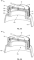
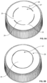
- a screw top closure 10 has a two piece design.
- An outermost cap 20 includes threads, flanges, tabs, or other means to affix cap 20 to container 100 with corresponding structure on neck 102, thereby sealing the container opening 104.
- cap 20 retains an inner disk 30 with anti-back off ribs 32 (as seen in Figures 2-4 ) to limit the rotation of the inner disk 30.
- the threads 21 (or other engagement mechanisms) secure the closure 10 to the container 100 by way of corresponding threads 106.
- the back-off ribs 32 come into contact with corresponding posts, ribs, or stops 108 formed near the opening 104 along the neck 102, while the inner disk 30 itself is compressed against the inner facing (i.e., the underside) of the cap 20.
- the ribs 32 need only have a thickness of less than 3.00 mm (as measured in a transverse plane relative to the longitudinal axis of the container), and more preferably less than 2.50 mm or even less than 2.0 mm, although in all cases the thickness of the ribs will be discernibly greater than the thickness of the container itself (i.e., its average thickness and/or its average thickness within the neck area). In this manner, significant savings can be realized owing to the reduced volume of materials required in comparison to known container designs employing backoff ribs for other purposes.
- a post 23 may be formed along the inner facing of the cap 20. Post 23 is urged into a receptacle 33 formed on the corresponding facing of the disc 30. The converse (post on the disc and receptacle on the cap) is also possible. Thus, when the closure 10 is initially tightened/affixed onto the container 100, the post 23 is urged into the receptacle 33 to hold the cap 20 and disc 30 together. Multiple post-receptacles may be formed, despite the fact only one centralized pair is depicted in these drawings. Also, by holding the cap 20 and disc 30 together in this fashion, the anti-rotation ribs 22 (as described below) can function effectively.
- Ribs 22 are provided on the inner facing of the cap 20 to engage corresponding structures on the disc. Ribs 22 may possess a wedge-like shape to allow rotation in one direction but not the reverse direction. In this manner, once the disc 30 rotates relative to the cap 20, it cannot return to its original position.
- a central section 24 is concentrically located on the top of cap 20. This section 24 may be connected to the outer periphery of the cap 20 by way of bridging tabs 25.
- the tabs 25 will be of a construction to allow them to break/disconnect the central section 24 from the remainder of cap 20, particularly when the anti-rotation ribs 22 are engaged. Thereafter, section 24 moves in concert with disc 30.
- indicia or markings 26, 27 are provided separately on the cap periphery and the central section 24.
- the indicia 26, 27 move relative to one another, with this misalignment providing an indication of tampering/opening of the container.
- a viewing window it is possible for a viewing window to be formed in central section 24 to expose an initial indicator on the top-facing of the disc 30.
- this initial indicator is no longer visible.
- the bridges 25 in order for section 24 to rotate relative to the periphery of cap 20, the bridges 25 (if present) must be disconnected/broken).
- a serialization number may be provided on the cap 20; for example, within the central section 24.
- the number may serve as a unique identifier for that cap/container combination (i.e., the product), as well as to accomplish any of the other objects described below.
- the number may be printed, etched, stamped, labeled, or integrally formed (e.g., by way of one or two shot molding).
- other optical indicators as described below can be incorporated in a similar manner.
- the ideal thickness of the back off ribs provided on the container neck can be expressed relative to as a ratio in comparison to the standardized dimensions of bottle openings, as defined by the Glass Packaging Institute (GPI) and/or Society of Plasitics Industry (SPI).
- the thickness of the ribs may be any one onehundredth integer between 1.00 mm and 3.00 mm, while the inner diameter may be 400, 410, 415, 425, 430, 2030, or 2035 sized. Any combination of these disclosed aspects are included.
- the inner facing of the cap also contains anti-rotation ribs and an optional snap fit post that is received within a recess on the inner disk (conversely, the disk may be provided with a post and the cap with a corresponding recess).
- these structures on the inner facing of the cap cooperate to allow only partial rotation of the inner disk when the closure is tightened and then released (e.g., via rotation and/or torque).
- this partial rotation is effectively irreversible (i.e., the cap and inner disk cannot easily be reset to their original positions).
- the user can quickly verify that the closure has been previously removed from the container. In turn, the user can be assured that the container has not been tampered with or surreptitiously refilled.
- the indicators could be as simple as arrows that are aligned when the closure is secured onto the container. Thus, a gap or series of gaps may be visible on the outer facing of the cap/closure, and the arrows would not be aligned when the closure is initially released from the container.
- the indicator could be a stress-induced structure that is at least temporarily attached to the cap and inner disk.
- the stress-induced structure would break, change color, or provide some other visual when sufficient rotation/torque is applied to initially release the closure.
- Any number of polymers may be suitable to provide stress-induced indications contemplated herein.
- An electrical circuit and/or electrically powered component can be incorporated into the structure described above. That is, a conductive material (e.g., metal, metal wire, conductive polymer(s), etc.) is formed into the outermost cap and, separately, into the inner disk. When the closure is initially formed, the two separate materials are aligned to allow the flow of electricity therethrough. Conversely, when torque is initially applied, the action of the cap, disk, and back off ribs cause the electrical flowpath to be disrupted so as to eliminate the supply of electricity and enable the anti-counterfeiting and other aims of this invention.
- a conductive material e.g., metal, metal wire, conductive polymer(s), etc.
- a conductive polymer may be molded or formed into the outermost cap, the inner disk, or both.
- Multiple step process e.g., over-molding, two shot, etc.
- conductive polymers in combination with conventional polymers By selectively using conductive polymers in combination with more conventional polymers, it may be possible to minimize costs by limiting the need/volume of expensive resins, improve upon the design and function of the closure by selectively incorporating electrical flowpaths, and/or to enhance the aesthetics and performance of the closure by relying on conventional polymers and/or other materials that provide a wider range of options in these regards.
- two shot processes that minimize conductive resin simplify manufacturing.
- threshold levels for conductivity and resistance must be considered when selecting appropriate conductive resins (or other conductive/resistive components disclosed herein) so as to cooperate with cell phones and/or other aspects contemplated herein. Reference can be made to the attachment for further details.
- Conductive resin or conductive elements may protrude from the smooth surface of the cap. These elements are also interrupted when the closure is turned. In either or both of these manners, the conductive elements may provide additional means of detection of tampering, as well as potentially serving as frangible elements.
- a conductive foil may be incorporated to define the electrical flowpath(s) between components (e.g., disk and cap, integrated circuit and sensor, etc.).
- the foil could be captured between the cap and the closure to define an electrical flowpath between these components.
- the foil would be torn or physically compromised upon opening/torque being applied to the closure, thereby eliminating the conductive path.
- Conductive or inductive ink could be provided to the cap and the disk when in their original, manufactured state (i.e., prior to torqueing/displacement by rotation). Thus, the ink establishes the necessary and detectable electrical flowpath.
- the circuit or flowpath could include a simple visual indicator (e.g., activation or deactivation of a light emitting diode or other electrically responsive material). In other embodiments, it may include in its original manufactured state or require a subsequently provided integrated circuit or microprocessor (e.g., a user's hand held mobile device), with the use of additional computing power enabling a host of other web-based, remote access, and/or wireless features.
- a simple visual indicator e.g., activation or deactivation of a light emitting diode or other electrically responsive material
- it may include in its original manufactured state or require a subsequently provided integrated circuit or microprocessor (e.g., a user's hand held mobile device), with the use of additional computing power enabling a host of other web-based, remote access, and/or wireless features.
- the capacitive touch features found in touch screen devices e.g., phones, tablets, etc.
- a power source may be attached to or contained within the closure to supply power to such electromechanical mechanisms.
- a coin cell, button cell, or thin printed battery is encased between or within one of the cap and the disk.
- conductive resin can be molded (or conductive inks can be printed/applied, also as seen in Figure 9 ), on the central section 24, at least one of the tab 25, and the periphery of the cap 20.
- An optional power source can be disposed on either the cap 20 or the central section 24, and a tag or integrated chip could also be used.
- the conductive resin 28 or ink 29 is in or exposed along the top of the closure 10 so as to allow a user and/or computerized device or reader to touch or come into contact with the resin.
- the electrical flowpath created thereby can be used for any of the purposes described herein.
- the outer facing resin may be slightly raised from the top surface of the closure 10 to simplify these connections/contact.
- the resin/ink can also be provided solely on the exterior, top facings, rather than both the top and the bottom of cap 20 as shown.
- the power to verify the electrical circuit/connection need not be carried within the closure itself. That is, the closure could be configured so that further user intervention is required to supply power and/or to close the necessary electrical circuit (thereby selectively and temporarily powering the necessary components, such as an LED, integrated chip (IC), or other wireless or sensing device).
- the necessary components such as an LED, integrated chip (IC), or other wireless or sensing device.
- a solenoid or other movable part responsive to electric current could serve as an indicator.
- These elements could also be provided to serve as a valve, thereby blocking the flow of material through the closure and out of the container under certain circumstances.
- optical indicator could be used to proactively inform the user as to the contents and history of the closure/container assembly before it is first opened.
- the optical indicator could be initially concealed from a viewing window until after the product was opened.
- the user is only able to access information after the closure was opened/compromised.
- the user would need to be aware of and informed so as to avoid purchasing a product where the optical indicator was initially visible.
- a photoelectric ink could be coupled to a power source, as noted above, to provide a visual distinction between the closure in its original manufactured state in comparison to after torque has been applied and the disk and cap have moved relative to one another.
- an ink that is specifically detectable by a computing device e.g., capacitive detector, as might be found in a smart phone screen or a specialized color/wavelength that could be detected and verified by a camera
- a computing device e.g., capacitive detector, as might be found in a smart phone screen or a specialized color/wavelength that could be detected and verified by a camera
- active and/or passive approaches could be used.
- the ink could change in response to the opening or closing an electrical flowpath after the closure is displaced, while the later could simply provide a means for verifying the original, manufactured characteristics of the closure and/or container and product to which it is associated.
- the passive approach could be positioned on one of the closure's movable parts so as to make it viewable only before or after the closure is displaced.
- the inks used as optical indicators need not be photo- or electrically sensitive and, instead, may simply provide a unique signature that is detectable by a user controlled apparatus.
- Wireless technologies including radio frequency identification, near-field communications devices and protocols, and magnetic, capacitive, inductive, or other noncontact detection systems could be provided within the closure to serve the goals defined herein.
- the closure needs only to be proximate to a detector (e.g., an end user's hand held or mobile computing device).
- the detector itself then displays or otherwise communicates information captured by the wireless technology.
- the wireless technology might be as simple as a unique and/or serialized identifier.
- This identifier is associated with a database which then captures more descriptive information provided or maintained by the manufacturer or retailer.
- the technology may be programmed to communicate the desired information directly (via the detector) and without the need to communicate with a remotely located server or data provider.
- a wireless communication tag includes an electronic circuit with information stored thereon.
- the tag can be activated by a nearby reader device so as to wirelessly transmit the information to the nearby reader device.
- Information stored on the wireless communication tag pertains to the product within the container or packaging which the tag is associated. This information may be directly read and displayed by the device, or the information from the tag may enable the user, via the device, to engage in the web-based or remote access methods described below.
- the wireless communication tag used in the following aspects of the present invention may be an NFC tag, an RFID tag, or a Bluetooth device. Preferably, it is an NFC tag.
- a “passive tag” is defined as a tag without its own source of power. When a passive tag receives an electromagnetic (EM) signal from a nearby reader device, a portion of the energy of the signal is converted into a current, thereby powering (and activating) the tag. Passive tags are therefore only capable of transmitting information when activated by a nearby reader device. Passive tags are cheap to produce, and so are well suited for use in disposable or short-life intelligent packaging.
- EM electromagnetic
- an "active tag” is defined as a tag with its own source of power. Active tags are therefore capable of performing functions other than the simple transmission of information to a reader device. Furthermore, they can perform these additional functions without requiring power from a nearby reader device for activation. Active tags may respond to EM signals, radio signals, or visible or invisible (e.g., infrared) light.
- One or more tags may be embedded into a body of the packaging, by insert or over moulding, particularly where one or more active tags are used. Moreover, it may be embedded into a material of the body of the packaging, the container, the dispenser (if present, and/or closure of the container itself. Because the tag is embedded, it is not possible to tamper or copy the tag without visibly altering the appearance of the packaging. Accordingly, counterfeiting is prevented. The risk of the tag detaching from the packaging is also reduced, thereby improving the durability of the product packaging.
- Figure 10 shows how an inductive foil and/or a tag 50 could be captured or attached to the disc 30 along its inner facing. The act of affixing the closure 10 could be sufficient to hold the tag/foil 50 in place.
- a pump dispenser for dispensing a liquid or other flowable product such as paste or cream
- the pump dispenser incorporating a wireless communication tag
- the tag having information pertaining to the pump stored thereon, and being configured to wirelessly transmit information pertaining to the pump when activated by a reader device; wherein the tag is incorporated into a pump mechanism of the pump.
- An actuation component may be coupled with the tag, for implementing the dispensing regime.
- the actuation component may be a valve or other flow-influencing structure such as a weir in, at or around a flow conduit and configured to move, e.g. open and close, according to the dispensing regime.
- Such a valve might be operated, actuated or initiated by electromagnetic, induction, piezoelectric or other mechanism.
- a MEMS (microelectromechanical) component may be used.
- the pump dispenser may be reusable or disposable.
- the dispenser may be a pump dispenser typically comprising a body and a plunger reciprocable relative to the body to alter the volume of a pump chamber defined in the body, such as by a piston and cylinder or bellows action, the pump chamber having an inlet to receive product from a reservoir thereof such as a container attached to the pump dispenser, and an outlet leading to a discharge channel.
- the inlet and/or outlet have a check valve.
- Preferred pumps have a plunger with an actuator head and a stem which carries a piston acting in a cylinder of the pump body.
- the container includes a user-operated dispensing mechanism for dispensing a product, such as piston pump or squeeze pump.
- the dispense mechanism includes an integrated active wireless communication tag having information pertaining to the product stored thereon. Actuation of the dispense mechanism to dispense the product may also generate an electrical signal, by way of a transducer, that is used to update the information and/or power an active tag. Additionally or alternatively, actuation may also be recorded by the tag or serve as a trigger for transmission of information from the tag, so as to allow for tracking of the total quantity of dispensed product and other, related information.
- the tag may interact with the device to update the information on the tag.
- This update could impose a new dispensing regime, prevent use under certain conditions, or otherwise inform the traits of the dispenser is used in the future.
- temporal thresholds could be incorporated and/or altered in this manner so as to impose a minimum time or some other time-based restriction.
- quantitative thresholds could be employed to impose maximums or other limitations, e.g., by adjustment of the duration of dispensing, the flow rate (via changes to the pumping or outlet port), etc..
- a power source can be provided, particularly in embodiments with active tags, in order to activate or selectively enable the wireless functionality.
- This power source may be in the form of a thin-printed, coin, button cell, cylindrical or other type of battery. Selection of the power source will be dictated by the need for electrical current, lifespan of the battery, and the size and shape(s) into which the power source must be integrated.
- one or more transducers can be provided within or proximate to the tag.
- transducers convert mechanical energy (i.e., in the form of motion) into electrical energy.
- Such transducers could be incorporated on one of the moving parts of a pump, as shown in Figures 11 and 12 . That is, as the actuator for the dispenser moves through its range of motion, a cooperating transducer converts the energy from that movement into a usable electrical signal, e.g., to power an active tag.
- a transducer is a piezoelectric device.
- pump dispenser 600 is attached, via a closure with a fastening formation such as a thread 604, to a container 602 containing a liquid product (not shown) to be dispensed.
- a fastening formation such as a thread 604
- Pump dispenser 600 itself comprises a main body 606, shaft 608, and pump head 610.
- a shaft 608 comprised with the head in a plunger of the pump mechanism is forced into reservoir 602.
- an internal pump mechanism (not shown) causes the liquid to be drawn or forced up the tube shown and out through the shaft 608, and dispensed from an outlet in the pump head 612.
- the mechanism is typically a piston and cylinder mechanism, as discussed above.
- transducer 616 When a user performs a pump cycle, transducer 616, which is coupled to the pump mechanism, is deformed. As the piezoelectric is deformed, it produces an electrical signal, which in turn is fed into tag 618, thereby providing power for operating the tag 618. Accordingly, each time the pump is actuated by a user, power is supplied to tag 618. Accordingly, the active tag can operate without the need of a battery.
- a dosing dispenser mechanism 70 for dispensing a fluid in separate doses from a reservoir 708, desirably a resiliently squeezable container.
- Dispenser mechanism 70 comprises a closure cap 702, outlet tube 700, timing chamber 706, occluder 704 and timing aperture 710.
- Dispenser mechanism 70 and reservoir 708 are shown in an upright position in Fig. 7 .
- the dispenser mechanism 70 and reservoir 708 are upturned, i.e. so that the fluid flows into closure cap 702, fluid is dispensed.
- fluid flows into the timing chamber 706 and out of outlet tube 700.
- fluid flows through timing aperture 710, thereby enabling occluder 704 to gradually move towards outlet tube 700 (where the speed at which it moves is regulated by the size of the timing aperture 710).
- the occluder 704 reaches the outlet tube 700, the outlet is blocked so that no more fluid can be dispensed and the dose terminates.
- the dispenser can then be returned to an upright position, thereby enabling the occluder to return to its original position, ready for more fluid to be dispensed.
- the dispenser 70 further incorporates a wireless tag (not shown) configured to impose a dispensing regime.
- a wireless tag configured to impose a dispensing regime.
- the wireless tag by providing the wireless tag with an actuator component for adjusting the diameter of the timing aperture 710, the speed at which the obturator moves towards the inlet opening and hence the dose size can be controlled.
- the tag when a reader device communicates with the tag to reduce the amount of fluid dispensable in each dispense operation, the tag will then control the actuator component to reduce the diameter of the timing aperture 710, and in turn reduce the amount of fluid dispensable each time the dispenser is used.
- the tag may be provided with one or more sensors, integrated chips, memory devices, and/or related circuitry (collectively referred to hereafter as “sensors and circuitry”) to accomplish the aims described herein.
- sensors and circuitry are hard-wired and preferably molded along with the tag to ensure a durable construction.
- Components associated with one or more of the foregoing groupings can be combined with remotely located data servers.
- These data servers may merely store information or allow for dynamic and interactive aspects of the product to be developed.
- any number of arrangements could allow for authentication of the closure (and its associated container/products), cataloging of an end user's preferences or habits, serialization of the product itself by a middle party (e.g., a wholesaler or retailer), and other purposes as contemplated herein.
- a preferred embodiment would involve the creation of an application or other software routine that is then installed on a user controlled computing device (e.g., a smart phone, a tablet, an e-reader, a laptop or mobile computer, etc.) equipped with appropriate wireless technologies (e.g., near field communications detectors, cameras, other sensors, etc.).
- a user controlled computing device e.g., a smart phone, a tablet, an e-reader, a laptop or mobile computer, etc.
- appropriate wireless technologies e.g., near field communications detectors, cameras, other sensors, etc.
- the application can include functionality to identify one or more users.
- the user(s)' information may be stored within the memory of the device running the application, remotely on a data server, or both (with periodic synchronization schemes provided).
- the user may log-in using a profile in the application, so that any further activity during that log-in is automatically cataloged and indexed to that user.
- Algorithms could then be applied to further optimize the application and any information returned to the user from the remote servers (e.g., pertinent product information, opportunities to purchase related, ancillary products, etc.).
- geographic location devices associated with the computing device could be utilized to further augment the profile, algorithms, and/or overall user experience as might be appropriate to the circumstances.
- the remote storage of data allows for iterative treatment of data about the user, the closure, and/or the product within the container associated with the closure. That is, information about a particular closure may be created and added to as time goes on (this could prove particularly useful in an arrangement where a user might access information prior to and in support of a prospective purchase/use).
- data may be collected, tracked, and supplemented based on a wider scale.
- Data storage may be leveraged on reader devices (e.g., mobile phones, laptop computers, etc.) that may be initially employed to interact with the closures and/or tags contemplated herein.
- reader devices e.g., mobile phones, laptop computers, etc.
- user profiles, dispensing and usage habits, and other traits can be stored on the reader device so as to interact directly with the closure/tag, thereby accomplishing the steps noted above.
- the invention may include serialization by a middle party. That is, the closure may be formed with components from any combination of the groupings above, while the middle party provides a remote data server.
- the middle party could create or assign productspecific information to a specific closure based upon the circumstances of the transaction by which the end user comes into possession of the closure.
- this serialization could include an iterative element by which subsequent communications/requests from the end user about the specific closure are further tracked and leveraged.
- a middle party could be a wholesaler, a retailer, a distributor within a supply chain, or any other entity that intervenes from the initial manufacture and containment of the product (via the inventive closure) and the final end user.
- the information pertaining to the product may include one or more of the following:
- the sensors and other circuitry that might be useful in combination with the tags include any one or more of:
- NFC tags of the type discussed in this application can store data typically up to 8kB, it is envisioned that any suitable combination of types of information could be used.
- the closure and method of closing contemplated herein provides one or more indicators for the user to easily determine whether the container has been compromised (i.e., without the user's knowledge, previously opened and/or surreptitiously adulterated/altered and then resealed). Therefore, methods of detecting counterfeit products, methods of serializing a product for subsequent, product- or user-specific datatracking, methods of authenticating the origin, contents, post-manufacturing history, and other characteristics of a closure associated with a specific product, and other methods are disclosed and encompassed by this disclosure.
- All components should be made of materials having sufficient flexibility and structural integrity, as well as a chemically inert nature. The materials should also be selected for workability, cost, and weight. Common polymers amenable to injection molding, extrusion, or other common forming processes should have particular utility, although metals, alloys, and other composites may be used in place of or in addition to more conventional container and closure materials.
Landscapes
- Engineering & Computer Science (AREA)
- Mechanical Engineering (AREA)
- Physics & Mathematics (AREA)
- Theoretical Computer Science (AREA)
- Computer Hardware Design (AREA)
- Microelectronics & Electronic Packaging (AREA)
- General Physics & Mathematics (AREA)
- Computer Networks & Wireless Communication (AREA)
- Signal Processing (AREA)
- Electromagnetism (AREA)
- Closures For Containers (AREA)
- Cartons (AREA)
- Burglar Alarm Systems (AREA)
- Data Exchanges In Wide-Area Networks (AREA)
- Details Of Rigid Or Semi-Rigid Containers (AREA)
- Financial Or Insurance-Related Operations Such As Payment And Settlement (AREA)
- Lock And Its Accessories (AREA)
- Management, Administration, Business Operations System, And Electronic Commerce (AREA)
Claims (15)
- Fälschungssicherer Verschluss (10), der an einer Öffnung auf einem Behälter anbringbar ist, umfassend:eine Kappe (20), die drehbar an der Öffnung anbringbar ist;eine Scheibe (30), die auf einer Unterseitenfläche der Kappe eingepasst ist, um die Scheibe zwischen der Kappe und dem Behälter zu fixieren, wenn ein schließendes Drehmoment angewendet wird, um den Verschluss an der Öffnung anzubringen, wobei zumindest eine Verdrehsicherungs-Rippe (22) auf der Innenfläche der Kappe (20) ausgebildet ist, um mit der Scheibe (30) in Eingriff zu geraten; undein Drahtloskommunikationsetikett (50);wobei zumindest eine Rückwärtsdrehsicherungs-Rippe (32) auf der Scheibe (30) ausgebildet ist, dadurch gekennzeichnet, dass, wenn ein öffnendes Drehmoment angewendet wird, um den Verschluss (10) von dem Behälter zu lösen, die zumindest eine Rückwärtsdrehsicherungs-Rippe (32) mit dem Behälter in Eingriff gerät, um zu bewirken, dass sich die Kappe (20) in Bezug auf die Scheibe (30) dreht;wobei die Kappe (20) einen Mittelabschnitt (24) umfasst;wobei die zumindest eine Rückwärtsdrehsicherungs-Rippe auf dem Mittelabschnitt ausgebildet ist;wobei zumindest eine Laschenbrücke (25) anfänglich den Mittelabschnitt (24) mit einem Umfangsabschnitt der Kappe verbindet und wobei die zumindest eine Laschenbrücke (25) bei Eingreifen der zumindest einen Rückwärtsdrehsicherungs-Rippe (32) abgetrennt wird; undwobei das Drahtloskommunikationsetikett (50) entlang der Laschenbrücke (25) aufgenommen ist.
- Verschluss nach Anspruch 1, ferner umfassend ein Aufnahmeelement (33), das auf der Scheibe (30) aufgenommen ist, um eine entsprechende Ausbuchtung (23), die auf der Kappe (20) ausgebildet ist, aufzunehmen, um die Scheibe (30) und die Kappe (20) in Schnapp-Eingriff zu bringen, wenn das schließende Drehmoment angewendet wird.
- Verschluss nach Anspruch 2, ferner umfassend die zumindest eine Verdrehsicherungs-Rippe (22) auf der Unterseitenfläche der Kappe (20), um zu ermöglichen, dass sich die Scheibe (30) nur in eine Richtung dreht.
- Verschluss nach Anspruch 1, ferner umfassend ein Aufnahmeelement, das auf der Kappe ausgebildet ist, um eine entsprechende Ausbuchtung aufzunehmen, die auf der Scheibe ausgebildet ist, um die Scheibe und die Kappe in Schnapp-Eingriff zu bringen, wenn das schließende Drehmoment angewendet wird.
- Verschluss nach Anspruch 4, ferner umfassend die zumindest eine Verdrehsicherungs-Rippe (22) auf der Unterseitenfläche der Kappe (20), um zu ermöglichen, dass sich die Scheibe (30) nur in eine Richtung dreht.
- Verschluss nach einem der Ansprüche 1 bis 5, wobei eine leitfähige Tinte oder ein leitfähiges Harz mit der Laschenbrücke (25) in Verbindung gebracht wird, um einen elektrischen Strompfad zwischen Elementen, die in der Nähe des Mittelabschnitts (24) angeordnet sind, und Elementen, die in der Nähe des Umfangsabschnitts angeordnet sind, zu erzeugen.
- Verschluss nach Anspruch 6, ferner umfassend eine Leistungsquelle, die mit dem elektrischen Strompfad verbunden ist.
- Verschluss nach Anspruch 6 oder 7, wobei die Elemente, die in der Nähe des Mittelabschnitts (24) angeordnet sind, zumindest einen hervorstehenden Kontakt auf einer extern freigelegten Fläche des Verschlusses (10) umfassen.
- Verschluss nach einem der Ansprüche 6 bis 8, wobei die Elemente, die in der Nähe des Umfangsabschnitts bereitgestellt sind, zumindest einen hervorstehenden Kontakt auf einer extern freigelegten Fläche des Verschlusses (10) umfassen.
- Verschluss nach einem der Ansprüche 6 bis 9, wobei der elektrische Pfad auf der Unterseitenfläche der Kappe (20) ausgebildet ist.
- Verschluss nach einem der vorangegangenen Ansprüche, wobei das Etikett zudem zumindest eines der Folgenden umfasst: eine elektromechanische Anzeige, ein webbasiertes Verifizierungsetikett, Serialisierungsangaben, optische Identifikatoren.
- Verschluss nach einem der vorangegangenen Ansprüche, wobei ein leitfähiges Harz über ein Zweistrahl-Formverfahren bereitgestellt wird, um zumindest einer aus der Kappe (20) und der Scheibe (30) ein Merkmal elektrischer Leitfähigkeit zu verleihen.
- Verschluss nach einem der vorangegangenen Ansprüche, wobei eine Vielzahl von Rückwärtsdrehsicherungs-Rippen (32) entlang eines äußersten Umfangs der Scheibe (30) ausgebildet ist.
- Verschluss nach einem der vorangegangenen Ansprüche, wobei Verdrehsicherungs-Rippen (22) innerhalb des Mittelabschnitts (24) ausgebildet sind, um eine Drehung des Umfangsabschnitts der Kappe (20) in Bezug auf die Scheibe (30) zu erleichtern.
- Verschluss nach Anspruch 14, wobei der Mittelabschnitt (24) der Kappe (20) mit der Scheibe (30) gekoppelt bleibt, wenn sich der Umfangsabschnitt der Kappe (20) dreht.
Applications Claiming Priority (3)
| Application Number | Priority Date | Filing Date | Title |
|---|---|---|---|
| GBGB1701133.9A GB201701133D0 (en) | 2017-01-23 | 2017-01-23 | Packaging |
| US201762592453P | 2017-11-30 | 2017-11-30 | |
| PCT/US2018/014825 WO2018136927A1 (en) | 2017-01-23 | 2018-01-23 | Closure for container with informational and/or anti-counterfeiting capabilities |
Publications (3)
| Publication Number | Publication Date |
|---|---|
| EP3571129A1 EP3571129A1 (de) | 2019-11-27 |
| EP3571129A4 EP3571129A4 (de) | 2020-12-16 |
| EP3571129B1 true EP3571129B1 (de) | 2023-10-25 |
Family
ID=58463117
Family Applications (1)
| Application Number | Title | Priority Date | Filing Date |
|---|---|---|---|
| EP18741836.3A Active EP3571129B1 (de) | 2017-01-23 | 2018-01-23 | Verschluss für behälter mit informations- oder fälschungssicherungsfähigkeiten |
Country Status (9)
| Country | Link |
|---|---|
| US (2) | US11008143B2 (de) |
| EP (1) | EP3571129B1 (de) |
| CN (1) | CN110461726A (de) |
| AU (1) | AU2018210005B2 (de) |
| BR (1) | BR112019015064B1 (de) |
| GB (1) | GB201701133D0 (de) |
| MY (1) | MY204488A (de) |
| RU (1) | RU2752103C2 (de) |
| WO (1) | WO2018136927A1 (de) |
Families Citing this family (20)
| Publication number | Priority date | Publication date | Assignee | Title |
|---|---|---|---|---|
| US11542080B2 (en) * | 2013-05-07 | 2023-01-03 | BBB Holding Company | Track and trace packaging and systems |
| EP3263473A1 (de) * | 2016-06-27 | 2018-01-03 | Amcor Flexibles Capsules France | Intelligente kapseln |
| US10390201B2 (en) * | 2017-07-13 | 2019-08-20 | Pepsico, Inc. | Interactive closure device and beverage container |
| DE102019102213A1 (de) | 2019-01-29 | 2020-07-30 | Closurelogic Gmbh | Flaschenkappe |
| EP3696752A1 (de) * | 2019-02-13 | 2020-08-19 | Validicity Sweden AB | Auf manipulationssicherem rfid basierendes system und verfahren |
| GB2583948A (en) * | 2019-05-15 | 2020-11-18 | Greif Int Holding Bv | Tamper evident closure |
| ES1234399Y (es) * | 2019-07-19 | 2019-12-05 | Pujolasos S L | Tapón biodegradable |
| EP3770079A1 (de) * | 2019-07-26 | 2021-01-27 | PACCOR Packaging GmbH | Vorrichtung zum verschliessen einer gewindehalses eines behälters mit originalitätssicherung |
| US11205214B2 (en) | 2019-07-29 | 2021-12-21 | Luke MARIETTA | Method and system for automatically replenishing consumable items |
| CN114746344B (zh) * | 2019-10-01 | 2024-05-17 | 里克包装系统有限公司 | 具有信息化和/或防伪造功能的可回收容器封闭件 |
| US20210147118A1 (en) * | 2019-11-20 | 2021-05-20 | ARK Operations, Inc. | Systems and methods for tracking chain of custody of a container and its contents |
| US12122574B2 (en) * | 2019-12-18 | 2024-10-22 | Datwyler Pharma Packaging Belgium | Closure arrangement for a vessel containing a pharmaceutical substance |
| CN111547372B (zh) * | 2020-06-15 | 2024-09-20 | 成都市联余精密机械有限公司 | 定向撕裂的顶穿盖、水桶及桶装水 |
| US11481590B1 (en) * | 2020-08-17 | 2022-10-25 | Express Scripts Strategic Development, Inc. | Pill bottles with conductive ink and reading systems and methods |
| CN112027342B (zh) * | 2020-08-25 | 2022-02-18 | 上海亲启科技有限公司 | 一种物联网智能防伪装置及其防伪方法 |
| CN115219270B (zh) * | 2021-06-30 | 2025-08-01 | 北京云端光科技术有限公司 | 液体采样瓶的盖体、液体采样瓶、液体采样装置和注液枪 |
| FR3129142B1 (fr) * | 2021-11-15 | 2024-03-01 | Sigfox | Emballage connecté et procédé d’activation associé |
| WO2024047426A1 (en) * | 2022-08-30 | 2024-03-07 | Plasdan Automação E Sistemas | Screw cap device system |
| USD1074432S1 (en) | 2023-03-24 | 2025-05-13 | Waters Technologies Corporation | Bottle cap |
| WO2024206094A1 (en) | 2023-03-24 | 2024-10-03 | Waters Technologies Corporation | Solvent tube management |
Family Cites Families (22)
| Publication number | Priority date | Publication date | Assignee | Title |
|---|---|---|---|---|
| US4446979A (en) * | 1981-10-09 | 1984-05-08 | Sunbeam Plastics Corporation | Tamper indicating closure |
| SU1224217A1 (ru) * | 1983-06-16 | 1986-04-15 | Марийский Ордена Дружбы Народов Политехнический Институт Им.А.М.Горького | Затвор |
| US5638970A (en) * | 1989-02-03 | 1997-06-17 | Senetics, Inc. | Child-resistant indicator cap |
| US6879876B2 (en) * | 2001-06-13 | 2005-04-12 | Advanced Technology Materials, Inc. | Liquid handling system with electronic information storage |
| JP4489082B2 (ja) * | 2003-12-12 | 2010-06-23 | クレセンス、フランシス・エム | 製品に対する税が支払われているか否かを電子的に判定するための装置 |
| BRPI0509726A (pt) * | 2004-04-08 | 2007-09-25 | Famart Distrib Co N V | tampa de vedação à prova de violação |
| US7098794B2 (en) * | 2004-04-30 | 2006-08-29 | Kimberly-Clark Worldwide, Inc. | Deactivating a data tag for user privacy or tamper-evident packaging |
| US20070069021A1 (en) * | 2005-09-27 | 2007-03-29 | Palo Alto Research Center Incorporated | Smart floor tiles/carpet for tracking movement in retail, industrial and other environments |
| CA2625359A1 (en) * | 2005-10-11 | 2007-04-19 | Blake Podaima | Smart medical compliance method and system |
| US7342501B2 (en) * | 2006-02-07 | 2008-03-11 | Owens-Illinois Healthcare Packaging Inc. | Closure and package with induction seal and RFID tag |
| US7839288B2 (en) * | 2006-06-26 | 2010-11-23 | Chung Hua University | Sealing detection mechanism using RFID tag for container |
| US20100141384A1 (en) * | 2008-12-04 | 2010-06-10 | Yeh-Shun Chen | Bottle cap having anti-counterfeit function and bottle using the same |
| KR101132856B1 (ko) * | 2009-04-15 | 2012-04-03 | 이헌보 | 위조 방지용 병마개 |
| KR20120092781A (ko) * | 2011-02-13 | 2012-08-22 | 김경중 | 재사용 방지 용기 및 뚜껑 |
| TW201236927A (en) | 2011-03-11 | 2012-09-16 | China Steel Corp | Anti-counterfeiting bottle |
| WO2013167701A1 (de) * | 2012-05-09 | 2013-11-14 | Schreiner Group Gmbh & Co. Kg | Verschlusselement für ein gefäss |
| TWM440942U (en) * | 2012-05-11 | 2012-11-11 | Wander Plastic Co | Anti-counterfeiting bottle cap |
| CN104411597B (zh) * | 2012-06-25 | 2016-08-17 | 东洋制罐集团控股株式会社 | 具有ic标签的复合容器盖 |
| JP6109566B2 (ja) * | 2012-12-28 | 2017-04-05 | 東洋製罐株式会社 | Icタグを備えて成る複合容器蓋及び包装容器 |
| US9637271B2 (en) * | 2013-03-15 | 2017-05-02 | Owens-Brockway Glass Container Inc. | Container with a medal |
| CN104973320A (zh) * | 2014-04-09 | 2015-10-14 | 清展科技股份有限公司 | 容器瓶口之封闭件结构 |
| GB2554952A (en) * | 2016-10-17 | 2018-04-18 | Parkside Flexibles Europe Ltd | Electronic identifier for packaging |
-
2017
- 2017-01-23 GB GBGB1701133.9A patent/GB201701133D0/en not_active Ceased
-
2018
- 2018-01-23 RU RU2019126458A patent/RU2752103C2/ru active
- 2018-01-23 EP EP18741836.3A patent/EP3571129B1/de active Active
- 2018-01-23 CN CN201880019790.4A patent/CN110461726A/zh active Pending
- 2018-01-23 US US16/479,407 patent/US11008143B2/en active Active
- 2018-01-23 BR BR112019015064-1A patent/BR112019015064B1/pt active IP Right Grant
- 2018-01-23 WO PCT/US2018/014825 patent/WO2018136927A1/en not_active Ceased
- 2018-01-23 AU AU2018210005A patent/AU2018210005B2/en active Active
- 2018-01-23 MY MYPI2019004228A patent/MY204488A/en unknown
-
2021
- 2021-05-17 US US17/322,134 patent/US20210269206A1/en not_active Abandoned
Also Published As
| Publication number | Publication date |
|---|---|
| US20210269206A1 (en) | 2021-09-02 |
| EP3571129A4 (de) | 2020-12-16 |
| RU2019126458A3 (de) | 2021-05-17 |
| WO2018136927A1 (en) | 2018-07-26 |
| AU2018210005B2 (en) | 2023-04-13 |
| AU2018210005A1 (en) | 2019-08-08 |
| BR112019015064A2 (pt) | 2020-03-03 |
| BR112019015064B1 (pt) | 2023-04-18 |
| RU2752103C2 (ru) | 2021-07-22 |
| CN110461726A (zh) | 2019-11-15 |
| US11008143B2 (en) | 2021-05-18 |
| EP3571129A1 (de) | 2019-11-27 |
| RU2019126458A (ru) | 2021-02-24 |
| MY204488A (en) | 2024-08-30 |
| GB201701133D0 (en) | 2017-03-08 |
| US20190382173A1 (en) | 2019-12-19 |
Similar Documents
| Publication | Publication Date | Title |
|---|---|---|
| US11008143B2 (en) | Closure for container with informational and/or anti-counterfeiting capabilities | |
| US7839288B2 (en) | Sealing detection mechanism using RFID tag for container | |
| CN114846475B (zh) | 可配置式防篡改系统和方法 | |
| EP3627415B1 (de) | System und verfahren zur überwachung der kühlkettenintegrität von umweltempfindlichem packgut | |
| US20090267729A1 (en) | Anti-counterfeiting system | |
| US20130110286A1 (en) | Fuel Dispenser Flow Meter Fraud Detection and Prevention | |
| WO2006021039A1 (en) | Beverage control system | |
| US20060010503A1 (en) | Product authentication system for preventing distribution of counterfeits in market | |
| US11691792B2 (en) | Recyclable container closure having informational and/or anti-counterfeiting capabilities | |
| US20200364523A1 (en) | System and method for flexible asset tracking tag | |
| US10565411B2 (en) | Detection of seal integrity on products using RFID | |
| EP3271882A1 (de) | Vorrichtung und verfahren zur überwachung eines flüssigen lebensmittels | |
| US20110115631A1 (en) | Electronic Label, Method for Monitoring Products and Method for Data Communication | |
| US20090037217A1 (en) | Multi-functional package system | |
| AU2016262987B2 (en) | Packaging authentication | |
| US20240362440A1 (en) | A method for identifying consumption of a food product held in a food package by using a mobile device |
Legal Events
| Date | Code | Title | Description |
|---|---|---|---|
| STAA | Information on the status of an ep patent application or granted ep patent |
Free format text: STATUS: THE INTERNATIONAL PUBLICATION HAS BEEN MADE |
|
| PUAI | Public reference made under article 153(3) epc to a published international application that has entered the european phase |
Free format text: ORIGINAL CODE: 0009012 |
|
| STAA | Information on the status of an ep patent application or granted ep patent |
Free format text: STATUS: REQUEST FOR EXAMINATION WAS MADE |
|
| 17P | Request for examination filed |
Effective date: 20190823 |
|
| AK | Designated contracting states |
Kind code of ref document: A1 Designated state(s): AL AT BE BG CH CY CZ DE DK EE ES FI FR GB GR HR HU IE IS IT LI LT LU LV MC MK MT NL NO PL PT RO RS SE SI SK SM TR |
|
| AX | Request for extension of the european patent |
Extension state: BA ME |
|
| DAV | Request for validation of the european patent (deleted) | ||
| DAX | Request for extension of the european patent (deleted) | ||
| A4 | Supplementary search report drawn up and despatched |
Effective date: 20201113 |
|
| RIC1 | Information provided on ipc code assigned before grant |
Ipc: B65D 55/00 20060101ALI20201109BHEP Ipc: B65D 51/24 20060101ALI20201109BHEP Ipc: B65D 55/12 20060101ALI20201109BHEP Ipc: G06K 19/07 20060101ALI20201109BHEP Ipc: B65D 41/34 20060101ALI20201109BHEP Ipc: B65D 55/02 20060101AFI20201109BHEP Ipc: B65D 41/04 20060101ALI20201109BHEP |
|
| GRAP | Despatch of communication of intention to grant a patent |
Free format text: ORIGINAL CODE: EPIDOSNIGR1 |
|
| STAA | Information on the status of an ep patent application or granted ep patent |
Free format text: STATUS: GRANT OF PATENT IS INTENDED |
|
| INTG | Intention to grant announced |
Effective date: 20230509 |
|
| GRAS | Grant fee paid |
Free format text: ORIGINAL CODE: EPIDOSNIGR3 |
|
| GRAA | (expected) grant |
Free format text: ORIGINAL CODE: 0009210 |
|
| STAA | Information on the status of an ep patent application or granted ep patent |
Free format text: STATUS: THE PATENT HAS BEEN GRANTED |
|
| AK | Designated contracting states |
Kind code of ref document: B1 Designated state(s): AL AT BE BG CH CY CZ DE DK EE ES FI FR GB GR HR HU IE IS IT LI LT LU LV MC MK MT NL NO PL PT RO RS SE SI SK SM TR |
|
| P01 | Opt-out of the competence of the unified patent court (upc) registered |
Effective date: 20230914 |
|
| REG | Reference to a national code |
Ref country code: GB Ref legal event code: FG4D |
|
| REG | Reference to a national code |
Ref country code: CH Ref legal event code: EP |
|
| REG | Reference to a national code |
Ref country code: DE Ref legal event code: R096 Ref document number: 602018059963 Country of ref document: DE |
|
| REG | Reference to a national code |
Ref country code: IE Ref legal event code: FG4D |
|
| REG | Reference to a national code |
Ref country code: LT Ref legal event code: MG9D |
|
| REG | Reference to a national code |
Ref country code: NL Ref legal event code: MP Effective date: 20231025 |
|
| REG | Reference to a national code |
Ref country code: AT Ref legal event code: MK05 Ref document number: 1624454 Country of ref document: AT Kind code of ref document: T Effective date: 20231025 |
|
| PG25 | Lapsed in a contracting state [announced via postgrant information from national office to epo] |
Ref country code: NL Free format text: LAPSE BECAUSE OF FAILURE TO SUBMIT A TRANSLATION OF THE DESCRIPTION OR TO PAY THE FEE WITHIN THE PRESCRIBED TIME-LIMIT Effective date: 20231025 |
|
| PG25 | Lapsed in a contracting state [announced via postgrant information from national office to epo] |
Ref country code: GR Free format text: LAPSE BECAUSE OF FAILURE TO SUBMIT A TRANSLATION OF THE DESCRIPTION OR TO PAY THE FEE WITHIN THE PRESCRIBED TIME-LIMIT Effective date: 20240126 |
|
| PG25 | Lapsed in a contracting state [announced via postgrant information from national office to epo] |
Ref country code: IS Free format text: LAPSE BECAUSE OF FAILURE TO SUBMIT A TRANSLATION OF THE DESCRIPTION OR TO PAY THE FEE WITHIN THE PRESCRIBED TIME-LIMIT Effective date: 20240225 |
|
| PG25 | Lapsed in a contracting state [announced via postgrant information from national office to epo] |
Ref country code: LT Free format text: LAPSE BECAUSE OF FAILURE TO SUBMIT A TRANSLATION OF THE DESCRIPTION OR TO PAY THE FEE WITHIN THE PRESCRIBED TIME-LIMIT Effective date: 20231025 |
|
| PG25 | Lapsed in a contracting state [announced via postgrant information from national office to epo] |
Ref country code: AT Free format text: LAPSE BECAUSE OF FAILURE TO SUBMIT A TRANSLATION OF THE DESCRIPTION OR TO PAY THE FEE WITHIN THE PRESCRIBED TIME-LIMIT Effective date: 20231025 |
|
| PG25 | Lapsed in a contracting state [announced via postgrant information from national office to epo] |
Ref country code: ES Free format text: LAPSE BECAUSE OF FAILURE TO SUBMIT A TRANSLATION OF THE DESCRIPTION OR TO PAY THE FEE WITHIN THE PRESCRIBED TIME-LIMIT Effective date: 20231025 |
|
| PG25 | Lapsed in a contracting state [announced via postgrant information from national office to epo] |
Ref country code: LT Free format text: LAPSE BECAUSE OF FAILURE TO SUBMIT A TRANSLATION OF THE DESCRIPTION OR TO PAY THE FEE WITHIN THE PRESCRIBED TIME-LIMIT Effective date: 20231025 Ref country code: IS Free format text: LAPSE BECAUSE OF FAILURE TO SUBMIT A TRANSLATION OF THE DESCRIPTION OR TO PAY THE FEE WITHIN THE PRESCRIBED TIME-LIMIT Effective date: 20240225 Ref country code: GR Free format text: LAPSE BECAUSE OF FAILURE TO SUBMIT A TRANSLATION OF THE DESCRIPTION OR TO PAY THE FEE WITHIN THE PRESCRIBED TIME-LIMIT Effective date: 20240126 Ref country code: ES Free format text: LAPSE BECAUSE OF FAILURE TO SUBMIT A TRANSLATION OF THE DESCRIPTION OR TO PAY THE FEE WITHIN THE PRESCRIBED TIME-LIMIT Effective date: 20231025 Ref country code: BG Free format text: LAPSE BECAUSE OF FAILURE TO SUBMIT A TRANSLATION OF THE DESCRIPTION OR TO PAY THE FEE WITHIN THE PRESCRIBED TIME-LIMIT Effective date: 20240125 Ref country code: AT Free format text: LAPSE BECAUSE OF FAILURE TO SUBMIT A TRANSLATION OF THE DESCRIPTION OR TO PAY THE FEE WITHIN THE PRESCRIBED TIME-LIMIT Effective date: 20231025 Ref country code: PT Free format text: LAPSE BECAUSE OF FAILURE TO SUBMIT A TRANSLATION OF THE DESCRIPTION OR TO PAY THE FEE WITHIN THE PRESCRIBED TIME-LIMIT Effective date: 20240226 |
|
| PG25 | Lapsed in a contracting state [announced via postgrant information from national office to epo] |
Ref country code: SE Free format text: LAPSE BECAUSE OF FAILURE TO SUBMIT A TRANSLATION OF THE DESCRIPTION OR TO PAY THE FEE WITHIN THE PRESCRIBED TIME-LIMIT Effective date: 20231025 Ref country code: RS Free format text: LAPSE BECAUSE OF FAILURE TO SUBMIT A TRANSLATION OF THE DESCRIPTION OR TO PAY THE FEE WITHIN THE PRESCRIBED TIME-LIMIT Effective date: 20231025 Ref country code: PL Free format text: LAPSE BECAUSE OF FAILURE TO SUBMIT A TRANSLATION OF THE DESCRIPTION OR TO PAY THE FEE WITHIN THE PRESCRIBED TIME-LIMIT Effective date: 20231025 Ref country code: NO Free format text: LAPSE BECAUSE OF FAILURE TO SUBMIT A TRANSLATION OF THE DESCRIPTION OR TO PAY THE FEE WITHIN THE PRESCRIBED TIME-LIMIT Effective date: 20240125 Ref country code: LV Free format text: LAPSE BECAUSE OF FAILURE TO SUBMIT A TRANSLATION OF THE DESCRIPTION OR TO PAY THE FEE WITHIN THE PRESCRIBED TIME-LIMIT Effective date: 20231025 Ref country code: HR Free format text: LAPSE BECAUSE OF FAILURE TO SUBMIT A TRANSLATION OF THE DESCRIPTION OR TO PAY THE FEE WITHIN THE PRESCRIBED TIME-LIMIT Effective date: 20231025 |
|
| PG25 | Lapsed in a contracting state [announced via postgrant information from national office to epo] |
Ref country code: DK Free format text: LAPSE BECAUSE OF FAILURE TO SUBMIT A TRANSLATION OF THE DESCRIPTION OR TO PAY THE FEE WITHIN THE PRESCRIBED TIME-LIMIT Effective date: 20231025 |
|
| PG25 | Lapsed in a contracting state [announced via postgrant information from national office to epo] |
Ref country code: CZ Free format text: LAPSE BECAUSE OF FAILURE TO SUBMIT A TRANSLATION OF THE DESCRIPTION OR TO PAY THE FEE WITHIN THE PRESCRIBED TIME-LIMIT Effective date: 20231025 |
|
| REG | Reference to a national code |
Ref country code: DE Ref legal event code: R097 Ref document number: 602018059963 Country of ref document: DE |
|
| PG25 | Lapsed in a contracting state [announced via postgrant information from national office to epo] |
Ref country code: SK Free format text: LAPSE BECAUSE OF FAILURE TO SUBMIT A TRANSLATION OF THE DESCRIPTION OR TO PAY THE FEE WITHIN THE PRESCRIBED TIME-LIMIT Effective date: 20231025 |
|
| PG25 | Lapsed in a contracting state [announced via postgrant information from national office to epo] |
Ref country code: SM Free format text: LAPSE BECAUSE OF FAILURE TO SUBMIT A TRANSLATION OF THE DESCRIPTION OR TO PAY THE FEE WITHIN THE PRESCRIBED TIME-LIMIT Effective date: 20231025 Ref country code: SK Free format text: LAPSE BECAUSE OF FAILURE TO SUBMIT A TRANSLATION OF THE DESCRIPTION OR TO PAY THE FEE WITHIN THE PRESCRIBED TIME-LIMIT Effective date: 20231025 Ref country code: RO Free format text: LAPSE BECAUSE OF FAILURE TO SUBMIT A TRANSLATION OF THE DESCRIPTION OR TO PAY THE FEE WITHIN THE PRESCRIBED TIME-LIMIT Effective date: 20231025 Ref country code: EE Free format text: LAPSE BECAUSE OF FAILURE TO SUBMIT A TRANSLATION OF THE DESCRIPTION OR TO PAY THE FEE WITHIN THE PRESCRIBED TIME-LIMIT Effective date: 20231025 Ref country code: DK Free format text: LAPSE BECAUSE OF FAILURE TO SUBMIT A TRANSLATION OF THE DESCRIPTION OR TO PAY THE FEE WITHIN THE PRESCRIBED TIME-LIMIT Effective date: 20231025 Ref country code: CZ Free format text: LAPSE BECAUSE OF FAILURE TO SUBMIT A TRANSLATION OF THE DESCRIPTION OR TO PAY THE FEE WITHIN THE PRESCRIBED TIME-LIMIT Effective date: 20231025 |
|
| PG25 | Lapsed in a contracting state [announced via postgrant information from national office to epo] |
Ref country code: MC Free format text: LAPSE BECAUSE OF FAILURE TO SUBMIT A TRANSLATION OF THE DESCRIPTION OR TO PAY THE FEE WITHIN THE PRESCRIBED TIME-LIMIT Effective date: 20231025 |
|
| PG25 | Lapsed in a contracting state [announced via postgrant information from national office to epo] |
Ref country code: MC Free format text: LAPSE BECAUSE OF FAILURE TO SUBMIT A TRANSLATION OF THE DESCRIPTION OR TO PAY THE FEE WITHIN THE PRESCRIBED TIME-LIMIT Effective date: 20231025 |
|
| PLBE | No opposition filed within time limit |
Free format text: ORIGINAL CODE: 0009261 |
|
| REG | Reference to a national code |
Ref country code: CH Ref legal event code: PL |
|
| STAA | Information on the status of an ep patent application or granted ep patent |
Free format text: STATUS: NO OPPOSITION FILED WITHIN TIME LIMIT |
|
| PG25 | Lapsed in a contracting state [announced via postgrant information from national office to epo] |
Ref country code: LU Free format text: LAPSE BECAUSE OF NON-PAYMENT OF DUE FEES Effective date: 20240123 |
|
| PG25 | Lapsed in a contracting state [announced via postgrant information from national office to epo] |
Ref country code: LU Free format text: LAPSE BECAUSE OF NON-PAYMENT OF DUE FEES Effective date: 20240123 |
|
| 26N | No opposition filed |
Effective date: 20240726 |
|
| PG25 | Lapsed in a contracting state [announced via postgrant information from national office to epo] |
Ref country code: BE Free format text: LAPSE BECAUSE OF NON-PAYMENT OF DUE FEES Effective date: 20240131 |
|
| PG25 | Lapsed in a contracting state [announced via postgrant information from national office to epo] |
Ref country code: CH Free format text: LAPSE BECAUSE OF NON-PAYMENT OF DUE FEES Effective date: 20240131 |
|
| PG25 | Lapsed in a contracting state [announced via postgrant information from national office to epo] |
Ref country code: SI Free format text: LAPSE BECAUSE OF FAILURE TO SUBMIT A TRANSLATION OF THE DESCRIPTION OR TO PAY THE FEE WITHIN THE PRESCRIBED TIME-LIMIT Effective date: 20231025 |
|
| PG25 | Lapsed in a contracting state [announced via postgrant information from national office to epo] |
Ref country code: SI Free format text: LAPSE BECAUSE OF FAILURE TO SUBMIT A TRANSLATION OF THE DESCRIPTION OR TO PAY THE FEE WITHIN THE PRESCRIBED TIME-LIMIT Effective date: 20231025 Ref country code: CH Free format text: LAPSE BECAUSE OF NON-PAYMENT OF DUE FEES Effective date: 20240131 Ref country code: BE Free format text: LAPSE BECAUSE OF NON-PAYMENT OF DUE FEES Effective date: 20240131 |
|
| REG | Reference to a national code |
Ref country code: BE Ref legal event code: MM Effective date: 20240131 |
|
| PG25 | Lapsed in a contracting state [announced via postgrant information from national office to epo] |
Ref country code: IE Free format text: LAPSE BECAUSE OF NON-PAYMENT OF DUE FEES Effective date: 20240123 |
|
| PG25 | Lapsed in a contracting state [announced via postgrant information from national office to epo] |
Ref country code: IE Free format text: LAPSE BECAUSE OF NON-PAYMENT OF DUE FEES Effective date: 20240123 |
|
| PG25 | Lapsed in a contracting state [announced via postgrant information from national office to epo] |
Ref country code: CY Free format text: LAPSE BECAUSE OF FAILURE TO SUBMIT A TRANSLATION OF THE DESCRIPTION OR TO PAY THE FEE WITHIN THE PRESCRIBED TIME-LIMIT; INVALID AB INITIO Effective date: 20180123 |
|
| PG25 | Lapsed in a contracting state [announced via postgrant information from national office to epo] |
Ref country code: HU Free format text: LAPSE BECAUSE OF FAILURE TO SUBMIT A TRANSLATION OF THE DESCRIPTION OR TO PAY THE FEE WITHIN THE PRESCRIBED TIME-LIMIT; INVALID AB INITIO Effective date: 20180123 |
|
| PG25 | Lapsed in a contracting state [announced via postgrant information from national office to epo] |
Ref country code: FI Free format text: LAPSE BECAUSE OF FAILURE TO SUBMIT A TRANSLATION OF THE DESCRIPTION OR TO PAY THE FEE WITHIN THE PRESCRIBED TIME-LIMIT Effective date: 20231025 |
|
| PG25 | Lapsed in a contracting state [announced via postgrant information from national office to epo] |
Ref country code: TR Free format text: LAPSE BECAUSE OF FAILURE TO SUBMIT A TRANSLATION OF THE DESCRIPTION OR TO PAY THE FEE WITHIN THE PRESCRIBED TIME-LIMIT Effective date: 20231025 |
|
| PGFP | Annual fee paid to national office [announced via postgrant information from national office to epo] |
Ref country code: GB Payment date: 20260127 Year of fee payment: 9 |
|
| PGFP | Annual fee paid to national office [announced via postgrant information from national office to epo] |
Ref country code: DE Payment date: 20260128 Year of fee payment: 9 |
|
| PGFP | Annual fee paid to national office [announced via postgrant information from national office to epo] |
Ref country code: IT Payment date: 20260121 Year of fee payment: 9 |
|
| PGFP | Annual fee paid to national office [announced via postgrant information from national office to epo] |
Ref country code: FR Payment date: 20260126 Year of fee payment: 9 |