EP3571018B1 - Tragbare assistenzvorrichtungen und verfahren zum betrieb - Google Patents
Tragbare assistenzvorrichtungen und verfahren zum betrieb Download PDFInfo
- Publication number
- EP3571018B1 EP3571018B1 EP18741272.1A EP18741272A EP3571018B1 EP 3571018 B1 EP3571018 B1 EP 3571018B1 EP 18741272 A EP18741272 A EP 18741272A EP 3571018 B1 EP3571018 B1 EP 3571018B1
- Authority
- EP
- European Patent Office
- Prior art keywords
- assistance device
- body interface
- elastic
- elastic portion
- wearable
- Prior art date
- Legal status (The legal status is an assumption and is not a legal conclusion. Google has not performed a legal analysis and makes no representation as to the accuracy of the status listed.)
- Active
Links
Images


Classifications
-
- A—HUMAN NECESSITIES
- A61—MEDICAL OR VETERINARY SCIENCE; HYGIENE
- A61B—DIAGNOSIS; SURGERY; IDENTIFICATION
- A61B5/00—Measuring for diagnostic purposes; Identification of persons
- A61B5/68—Arrangements of detecting, measuring or recording means, e.g. sensors, in relation to patient
- A61B5/6801—Arrangements of detecting, measuring or recording means, e.g. sensors, in relation to patient specially adapted to be attached to or worn on the body surface
- A61B5/6802—Sensor mounted on worn items
- A61B5/6811—External prosthesis
-
- A—HUMAN NECESSITIES
- A61—MEDICAL OR VETERINARY SCIENCE; HYGIENE
- A61F—FILTERS IMPLANTABLE INTO BLOOD VESSELS; PROSTHESES; DEVICES PROVIDING PATENCY TO, OR PREVENTING COLLAPSING OF, TUBULAR STRUCTURES OF THE BODY, e.g. STENTS; ORTHOPAEDIC, NURSING OR CONTRACEPTIVE DEVICES; FOMENTATION; TREATMENT OR PROTECTION OF EYES OR EARS; BANDAGES, DRESSINGS OR ABSORBENT PADS; FIRST-AID KITS
- A61F2/00—Filters implantable into blood vessels; Prostheses, i.e. artificial substitutes or replacements for parts of the body; Appliances for connecting them with the body; Devices providing patency to, or preventing collapsing of, tubular structures of the body, e.g. stents
- A61F2/50—Prostheses not implantable in the body
- A61F2/68—Operating or control means
- A61F2/70—Operating or control means electrical
- A61F2/72—Bioelectric control, e.g. myoelectric
-
- A—HUMAN NECESSITIES
- A61—MEDICAL OR VETERINARY SCIENCE; HYGIENE
- A61F—FILTERS IMPLANTABLE INTO BLOOD VESSELS; PROSTHESES; DEVICES PROVIDING PATENCY TO, OR PREVENTING COLLAPSING OF, TUBULAR STRUCTURES OF THE BODY, e.g. STENTS; ORTHOPAEDIC, NURSING OR CONTRACEPTIVE DEVICES; FOMENTATION; TREATMENT OR PROTECTION OF EYES OR EARS; BANDAGES, DRESSINGS OR ABSORBENT PADS; FIRST-AID KITS
- A61F5/00—Orthopaedic methods or devices for non-surgical treatment of bones or joints; Nursing devices ; Anti-rape devices
- A61F5/01—Orthopaedic devices, e.g. long-term immobilising or pressure directing devices for treating broken or deformed bones such as splints, casts or braces
- A61F5/02—Orthopaedic corsets
- A61F5/026—Back straightening devices with shoulder braces to force back the shoulder to obtain a correct curvature of the spine
-
- A—HUMAN NECESSITIES
- A61—MEDICAL OR VETERINARY SCIENCE; HYGIENE
- A61F—FILTERS IMPLANTABLE INTO BLOOD VESSELS; PROSTHESES; DEVICES PROVIDING PATENCY TO, OR PREVENTING COLLAPSING OF, TUBULAR STRUCTURES OF THE BODY, e.g. STENTS; ORTHOPAEDIC, NURSING OR CONTRACEPTIVE DEVICES; FOMENTATION; TREATMENT OR PROTECTION OF EYES OR EARS; BANDAGES, DRESSINGS OR ABSORBENT PADS; FIRST-AID KITS
- A61F5/00—Orthopaedic methods or devices for non-surgical treatment of bones or joints; Nursing devices ; Anti-rape devices
- A61F5/01—Orthopaedic devices, e.g. long-term immobilising or pressure directing devices for treating broken or deformed bones such as splints, casts or braces
- A61F5/02—Orthopaedic corsets
- A61F5/028—Braces for providing support to the lower back, e.g. lumbo sacral supports
-
- A—HUMAN NECESSITIES
- A61—MEDICAL OR VETERINARY SCIENCE; HYGIENE
- A61H—PHYSICAL THERAPY APPARATUS, e.g. DEVICES FOR LOCATING OR STIMULATING REFLEX POINTS IN THE BODY; ARTIFICIAL RESPIRATION; MASSAGE; BATHING DEVICES FOR SPECIAL THERAPEUTIC OR HYGIENIC PURPOSES OR SPECIFIC PARTS OF THE BODY
- A61H3/00—Appliances for aiding patients or disabled persons to walk about
-
- F—MECHANICAL ENGINEERING; LIGHTING; HEATING; WEAPONS; BLASTING
- F16—ENGINEERING ELEMENTS AND UNITS; GENERAL MEASURES FOR PRODUCING AND MAINTAINING EFFECTIVE FUNCTIONING OF MACHINES OR INSTALLATIONS; THERMAL INSULATION IN GENERAL
- F16D—COUPLINGS FOR TRANSMITTING ROTATION; CLUTCHES; BRAKES
- F16D13/00—Friction clutches
- F16D13/58—Details
-
- A—HUMAN NECESSITIES
- A61—MEDICAL OR VETERINARY SCIENCE; HYGIENE
- A61B—DIAGNOSIS; SURGERY; IDENTIFICATION
- A61B5/00—Measuring for diagnostic purposes; Identification of persons
- A61B5/24—Detecting, measuring or recording bioelectric or biomagnetic signals of the body or parts thereof
- A61B5/316—Modalities, i.e. specific diagnostic methods
- A61B5/389—Electromyography [EMG]
-
- A—HUMAN NECESSITIES
- A61—MEDICAL OR VETERINARY SCIENCE; HYGIENE
- A61F—FILTERS IMPLANTABLE INTO BLOOD VESSELS; PROSTHESES; DEVICES PROVIDING PATENCY TO, OR PREVENTING COLLAPSING OF, TUBULAR STRUCTURES OF THE BODY, e.g. STENTS; ORTHOPAEDIC, NURSING OR CONTRACEPTIVE DEVICES; FOMENTATION; TREATMENT OR PROTECTION OF EYES OR EARS; BANDAGES, DRESSINGS OR ABSORBENT PADS; FIRST-AID KITS
- A61F2/00—Filters implantable into blood vessels; Prostheses, i.e. artificial substitutes or replacements for parts of the body; Appliances for connecting them with the body; Devices providing patency to, or preventing collapsing of, tubular structures of the body, e.g. stents
- A61F2/02—Prostheses implantable into the body
- A61F2/30—Joints
- A61F2002/30001—Additional features of subject-matter classified in A61F2/28, A61F2/30 and subgroups thereof
- A61F2002/30316—The prosthesis having different structural features at different locations within the same prosthesis; Connections between prosthetic parts; Special structural features of bone or joint prostheses not otherwise provided for
- A61F2002/30329—Connections or couplings between prosthetic parts, e.g. between modular parts; Connecting elements
- A61F2002/30476—Connections or couplings between prosthetic parts, e.g. between modular parts; Connecting elements locked by an additional locking mechanism
- A61F2002/30482—Connections or couplings between prosthetic parts, e.g. between modular parts; Connecting elements locked by an additional locking mechanism using a locking cam
-
- A—HUMAN NECESSITIES
- A61—MEDICAL OR VETERINARY SCIENCE; HYGIENE
- A61F—FILTERS IMPLANTABLE INTO BLOOD VESSELS; PROSTHESES; DEVICES PROVIDING PATENCY TO, OR PREVENTING COLLAPSING OF, TUBULAR STRUCTURES OF THE BODY, e.g. STENTS; ORTHOPAEDIC, NURSING OR CONTRACEPTIVE DEVICES; FOMENTATION; TREATMENT OR PROTECTION OF EYES OR EARS; BANDAGES, DRESSINGS OR ABSORBENT PADS; FIRST-AID KITS
- A61F5/00—Orthopaedic methods or devices for non-surgical treatment of bones or joints; Nursing devices ; Anti-rape devices
- A61F5/01—Orthopaedic devices, e.g. long-term immobilising or pressure directing devices for treating broken or deformed bones such as splints, casts or braces
- A61F5/0102—Orthopaedic devices, e.g. long-term immobilising or pressure directing devices for treating broken or deformed bones such as splints, casts or braces specially adapted for correcting deformities of the limbs or for supporting them; Ortheses, e.g. with articulations
- A61F2005/0132—Additional features of the articulation
- A61F2005/0155—Additional features of the articulation with actuating means
-
- A—HUMAN NECESSITIES
- A61—MEDICAL OR VETERINARY SCIENCE; HYGIENE
- A61F—FILTERS IMPLANTABLE INTO BLOOD VESSELS; PROSTHESES; DEVICES PROVIDING PATENCY TO, OR PREVENTING COLLAPSING OF, TUBULAR STRUCTURES OF THE BODY, e.g. STENTS; ORTHOPAEDIC, NURSING OR CONTRACEPTIVE DEVICES; FOMENTATION; TREATMENT OR PROTECTION OF EYES OR EARS; BANDAGES, DRESSINGS OR ABSORBENT PADS; FIRST-AID KITS
- A61F5/00—Orthopaedic methods or devices for non-surgical treatment of bones or joints; Nursing devices ; Anti-rape devices
- A61F5/01—Orthopaedic devices, e.g. long-term immobilising or pressure directing devices for treating broken or deformed bones such as splints, casts or braces
- A61F5/0102—Orthopaedic devices, e.g. long-term immobilising or pressure directing devices for treating broken or deformed bones such as splints, casts or braces specially adapted for correcting deformities of the limbs or for supporting them; Ortheses, e.g. with articulations
- A61F2005/0132—Additional features of the articulation
- A61F2005/0158—Additional features of the articulation with locking means
-
- A—HUMAN NECESSITIES
- A61—MEDICAL OR VETERINARY SCIENCE; HYGIENE
- A61F—FILTERS IMPLANTABLE INTO BLOOD VESSELS; PROSTHESES; DEVICES PROVIDING PATENCY TO, OR PREVENTING COLLAPSING OF, TUBULAR STRUCTURES OF THE BODY, e.g. STENTS; ORTHOPAEDIC, NURSING OR CONTRACEPTIVE DEVICES; FOMENTATION; TREATMENT OR PROTECTION OF EYES OR EARS; BANDAGES, DRESSINGS OR ABSORBENT PADS; FIRST-AID KITS
- A61F5/00—Orthopaedic methods or devices for non-surgical treatment of bones or joints; Nursing devices ; Anti-rape devices
- A61F5/01—Orthopaedic devices, e.g. long-term immobilising or pressure directing devices for treating broken or deformed bones such as splints, casts or braces
- A61F5/0102—Orthopaedic devices, e.g. long-term immobilising or pressure directing devices for treating broken or deformed bones such as splints, casts or braces specially adapted for correcting deformities of the limbs or for supporting them; Ortheses, e.g. with articulations
- A61F2005/0132—Additional features of the articulation
- A61F2005/0179—Additional features of the articulation with spring means
-
- A—HUMAN NECESSITIES
- A61—MEDICAL OR VETERINARY SCIENCE; HYGIENE
- A61F—FILTERS IMPLANTABLE INTO BLOOD VESSELS; PROSTHESES; DEVICES PROVIDING PATENCY TO, OR PREVENTING COLLAPSING OF, TUBULAR STRUCTURES OF THE BODY, e.g. STENTS; ORTHOPAEDIC, NURSING OR CONTRACEPTIVE DEVICES; FOMENTATION; TREATMENT OR PROTECTION OF EYES OR EARS; BANDAGES, DRESSINGS OR ABSORBENT PADS; FIRST-AID KITS
- A61F5/00—Orthopaedic methods or devices for non-surgical treatment of bones or joints; Nursing devices ; Anti-rape devices
- A61F5/01—Orthopaedic devices, e.g. long-term immobilising or pressure directing devices for treating broken or deformed bones such as splints, casts or braces
- A61F5/0102—Orthopaedic devices, e.g. long-term immobilising or pressure directing devices for treating broken or deformed bones such as splints, casts or braces specially adapted for correcting deformities of the limbs or for supporting them; Ortheses, e.g. with articulations
- A61F2005/0188—Orthopaedic devices, e.g. long-term immobilising or pressure directing devices for treating broken or deformed bones such as splints, casts or braces specially adapted for correcting deformities of the limbs or for supporting them; Ortheses, e.g. with articulations having pressure sensors
-
- A—HUMAN NECESSITIES
- A61—MEDICAL OR VETERINARY SCIENCE; HYGIENE
- A61F—FILTERS IMPLANTABLE INTO BLOOD VESSELS; PROSTHESES; DEVICES PROVIDING PATENCY TO, OR PREVENTING COLLAPSING OF, TUBULAR STRUCTURES OF THE BODY, e.g. STENTS; ORTHOPAEDIC, NURSING OR CONTRACEPTIVE DEVICES; FOMENTATION; TREATMENT OR PROTECTION OF EYES OR EARS; BANDAGES, DRESSINGS OR ABSORBENT PADS; FIRST-AID KITS
- A61F5/00—Orthopaedic methods or devices for non-surgical treatment of bones or joints; Nursing devices ; Anti-rape devices
- A61F5/01—Orthopaedic devices, e.g. long-term immobilising or pressure directing devices for treating broken or deformed bones such as splints, casts or braces
- A61F2005/0197—Orthopaedic devices, e.g. long-term immobilising or pressure directing devices for treating broken or deformed bones such as splints, casts or braces with spring means
-
- A—HUMAN NECESSITIES
- A61—MEDICAL OR VETERINARY SCIENCE; HYGIENE
- A61F—FILTERS IMPLANTABLE INTO BLOOD VESSELS; PROSTHESES; DEVICES PROVIDING PATENCY TO, OR PREVENTING COLLAPSING OF, TUBULAR STRUCTURES OF THE BODY, e.g. STENTS; ORTHOPAEDIC, NURSING OR CONTRACEPTIVE DEVICES; FOMENTATION; TREATMENT OR PROTECTION OF EYES OR EARS; BANDAGES, DRESSINGS OR ABSORBENT PADS; FIRST-AID KITS
- A61F5/00—Orthopaedic methods or devices for non-surgical treatment of bones or joints; Nursing devices ; Anti-rape devices
- A61F5/01—Orthopaedic devices, e.g. long-term immobilising or pressure directing devices for treating broken or deformed bones such as splints, casts or braces
-
- A—HUMAN NECESSITIES
- A61—MEDICAL OR VETERINARY SCIENCE; HYGIENE
- A61H—PHYSICAL THERAPY APPARATUS, e.g. DEVICES FOR LOCATING OR STIMULATING REFLEX POINTS IN THE BODY; ARTIFICIAL RESPIRATION; MASSAGE; BATHING DEVICES FOR SPECIAL THERAPEUTIC OR HYGIENIC PURPOSES OR SPECIFIC PARTS OF THE BODY
- A61H1/00—Apparatus for passive exercising; Vibrating apparatus; Chiropractic devices, e.g. body impacting devices, external devices for briefly extending or aligning unbroken bones
- A61H1/02—Stretching or bending or torsioning apparatus for exercising
- A61H1/0237—Stretching or bending or torsioning apparatus for exercising for the lower limbs
- A61H1/0255—Both knee and hip of a patient, e.g. in supine or sitting position, the feet being moved together in a plane substantially parallel to the body-symmetrical plane
- A61H1/0262—Walking movement; Appliances for aiding disabled persons to walk
-
- A—HUMAN NECESSITIES
- A61—MEDICAL OR VETERINARY SCIENCE; HYGIENE
- A61H—PHYSICAL THERAPY APPARATUS, e.g. DEVICES FOR LOCATING OR STIMULATING REFLEX POINTS IN THE BODY; ARTIFICIAL RESPIRATION; MASSAGE; BATHING DEVICES FOR SPECIAL THERAPEUTIC OR HYGIENIC PURPOSES OR SPECIFIC PARTS OF THE BODY
- A61H2201/00—Characteristics of apparatus not provided for in the preceding codes
- A61H2201/16—Physical interface with patient
- A61H2201/1602—Physical interface with patient kind of interface, e.g. head rest, knee support or lumbar support
- A61H2201/165—Wearable interfaces
-
- A—HUMAN NECESSITIES
- A61—MEDICAL OR VETERINARY SCIENCE; HYGIENE
- A61H—PHYSICAL THERAPY APPARATUS, e.g. DEVICES FOR LOCATING OR STIMULATING REFLEX POINTS IN THE BODY; ARTIFICIAL RESPIRATION; MASSAGE; BATHING DEVICES FOR SPECIAL THERAPEUTIC OR HYGIENIC PURPOSES OR SPECIFIC PARTS OF THE BODY
- A61H2201/00—Characteristics of apparatus not provided for in the preceding codes
- A61H2201/50—Control means thereof
- A61H2201/5007—Control means thereof computer controlled
-
- A—HUMAN NECESSITIES
- A61—MEDICAL OR VETERINARY SCIENCE; HYGIENE
- A61H—PHYSICAL THERAPY APPARATUS, e.g. DEVICES FOR LOCATING OR STIMULATING REFLEX POINTS IN THE BODY; ARTIFICIAL RESPIRATION; MASSAGE; BATHING DEVICES FOR SPECIAL THERAPEUTIC OR HYGIENIC PURPOSES OR SPECIFIC PARTS OF THE BODY
- A61H2201/00—Characteristics of apparatus not provided for in the preceding codes
- A61H2201/50—Control means thereof
- A61H2201/5058—Sensors or detectors
- A61H2201/5084—Acceleration sensors
-
- A—HUMAN NECESSITIES
- A61—MEDICAL OR VETERINARY SCIENCE; HYGIENE
- A61H—PHYSICAL THERAPY APPARATUS, e.g. DEVICES FOR LOCATING OR STIMULATING REFLEX POINTS IN THE BODY; ARTIFICIAL RESPIRATION; MASSAGE; BATHING DEVICES FOR SPECIAL THERAPEUTIC OR HYGIENIC PURPOSES OR SPECIFIC PARTS OF THE BODY
- A61H2230/00—Measuring physical parameters of the user
- A61H2230/60—Muscle strain, i.e. measured on the user, e.g. Electromyography [EMG]
-
- A—HUMAN NECESSITIES
- A63—SPORTS; GAMES; AMUSEMENTS
- A63B—APPARATUS FOR PHYSICAL TRAINING, GYMNASTICS, SWIMMING, CLIMBING, OR FENCING; BALL GAMES; TRAINING EQUIPMENT
- A63B21/00—Exercising apparatus for developing or strengthening the muscles or joints of the body by working against a counterforce, with or without measuring devices
- A63B21/15—Arrangements for force transmissions
- A63B21/151—Using flexible elements for reciprocating movements, e.g. ropes or chains
- A63B21/152—Bowden-type cables
-
- G—PHYSICS
- G05—CONTROLLING; REGULATING
- G05B—CONTROL OR REGULATING SYSTEMS IN GENERAL; FUNCTIONAL ELEMENTS OF SUCH SYSTEMS; MONITORING OR TESTING ARRANGEMENTS FOR SUCH SYSTEMS OR ELEMENTS
- G05B2219/00—Program-control systems
- G05B2219/30—Nc systems
- G05B2219/36—Nc in input of data, input key till input tape
- G05B2219/36435—Electromyographical, myoelectric control signal
Definitions
- the present invention relates to wearable devices, and more specifically to wearable devices for reducing lower back muscle stress, fatigue, injury and pain.
- Lower back pain is a disabling condition experienced by a high percentage of adults within their lifetimes. It is the leading cause of limited physical activity and the second leading cause of missed work in the U.S. and a significant economic burden. Lower back pain is estimated to cost $130-230 billion per year in the U.S. due to medical expenses and lost worker productivity.
- Lower back pain is particularly common among individuals who perform repetitive or heavy lifting, due to elevated loading on the lumbar spine that predisposes them to injury risk. Elevated and even moderate loads, applied repetitively to the lumbar spine can increase the risk of lower back pain, weaken or damage the vertebral bodies, and cause intervertebral disc degeneration and herniation. Prolonged leaning and other static postures are also potential risk factors for lower back pain. Combined compression and bending applied repetitively to cadaveric human lumbar spines often causes intervertebral disc injuries. Similarly, elevated and repetitive loading of tissues such as muscles and ligaments can cause strains and damage.
- the loading of lumbar muscles, ligaments, vertebrae and discs occurs repeatedly throughout the day during activities such as leaning, lifting, and even sitting.
- the majority of loading on the lumbar spine is the result of back muscles.
- Back muscles produce large forces and act at short moment arms about the intervertebral joints to balance moments from the upper-body and external objects.
- the lumbar spine experiences a large flexion moment during forward leaning of the trunk due to the weight of the upper-body and any additional external loads.
- the extension moment must be counterbalanced by an extension moment.
- the extension moment is provided by posterior lumbar muscles which apply forces roughly parallel to the spine. This compressive force caused by the back extensor muscles is exerted on the spine and can cause damage and pain.
- Assistance devices such as wearable robots have been designed for industrial or manual material handling work environments, but have form-factors that render them too bulky and impractical for daily at-home use or use in other business, social or clinical settings. For example, to maximize the moment arm and thus mechanical advantage, some of these assistance devices are designed with components that protrude significantly from the lower back. For a daily user, these design features can be restrictive, inhibiting basic activities such as sitting, lying down, stair ascent/descent, or navigating typical home or work environments. Due to the bulky designs, users are also required to wear these devices conspicuously on top of their clothing.
- an assistance device that can passively offload lumbar muscles and discs during leaning and lifting without restricting spine motion or increasing intra-abdominal pressure. Further, there is a need for such an assistance device to be lightweight, unobtrusive and simple to put on and take off. Finally, there is a need for an assistance device that provides reduced spinal compression forces.
- YUMEKO IMAMURA ET AL "Motion-based design of elastic belts for passive assistive device using musculoskeletal model” ROBOTICS AND BIOMIMETICS (ROBIO), 2011 IEEE INTERNATIONAL CONFERENCE ON, IEEE, 7 December 2011 (2011-12-07), pages 1343-1348 (XP032165973; DOI: 10.1109/ROBI0.2011.6181475; ISBN: 978-1-4577-2136-6 ) discloses a wearable lower back assistance device worn by a user, comprising:
- US 2016/107309 discloses a method for operating a wearable assistance device but does not disclose a clutch mechanism.
- a wearable lower back assistance device according to claim 1.
- the various embodiments are directed to wearable assistance devices, such as an exoskeleton or a garment, that can assist a wearer with leaning and lifting tasks.
- such assistance devices can provide a separate lumbar extension moment from the wearer's lower back when the wearer leans forward.
- Elastic bands in an exemplary embodiment provide equivalent extensor moments to the wearer's muscles with smaller force magnitudes.
- any other type of elastic member(s), viscoelastic member(s), or spring-type devices can be used in place of the elastic bands, as discussed in greater detail below. This results in reduced forces on the low back muscles, which then reduces lumbar disc loading.
- these wearable assistance devices can help mitigate overuse and overloading of the erector spinae muscles (and other back muscles and ligaments) that commonly leads to lower back injury and pain.
- the wearable assistance devices of the various embodiments are configured to transmit loads directly to the legs which allows forces to bypass the lower back muscles and the intervertebral discs.
- Wearable assistance devices in accordance with the various embodiments can assist with lifting, carrying or leaning tasks, transitioning from sit to stand or stand to sit, and other forms of locomotion. Further, the wearable assistance devices can be configured to span additional joints beyond the lower back such as the knee or neck to provide assistance for specific tasks.
- Wearable assistance devices can provide weak or strong assistance, corresponding to a lower degree of support or a higher degree of support, respectively, during a task.
- the transition from weak to strong assistance, or vice versa can be triggered by engaging a clutch mechanism that adjusts the strength of any devices that provide equivalent extensor moments to the wearer's muscles.
- the amount of assistance (assistive force) can be selected manually or can be triggered from signals receives from one or more wearable sensors. Such sensors can be separate or integrated into the wearable assistance device.
- FIG. 1 shows a simplified biomechanical model of lifting a box. The diagram is useful for demonstrating why high spinal forces arise from muscles acting at short moment arms.
- lifting and carrying a box can be modeled as a simple lever system where the fulcrum is located at the lumbar vertebrae and disc.
- FIG. 1 shows how the mass of a person's trunk and the mass of a carried weight applies a collective force to the spine.
- the trunk of a person contributes 400 Newtons (N) while the weight of the box contributes 200 N.
- N Newtons
- the lower back musculature must create a counter-acting moment to the forces.
- FIG. 1 shows a simplified biomechanical model of lifting a box. The diagram is useful for demonstrating why high spinal forces arise from muscles acting at short moment arms.
- lifting and carrying a box can be modeled as a simple lever system where the fulcrum is located at the lumbar vertebrae and disc.
- FIG. 1 shows how the mass of a person's trunk and the
- the muscle force required to provide this moment is 2000 N, which can be calculated based on the depicted moment arms.
- the total spine force is then the sum of the required muscle force, the force from the weight of the box, and the force from the weight of the person's trunk.
- the total spine force is 2600 N, of which 75% is due to the muscle force.
- FIG. 1 demonstrates how a simple lifting of a box can result in an excessive load on a person's spine.
- FIG. 2 illustrates the compression which occurs in the lumbar spine as a result of muscle and passive tissue forces during forward leaning.
- the region labeled A shows muscle attached to the lumbar spine which causes compression during leaning.
- the region labeled B refers to the tissue in between vertebrae spine which passively causes compression.
- the region labeled C shows how ligaments and other passive tissues act across a small moment.
- the majority of loading on the lumbar spine is the result of back muscles which produce large forces and act at short moment arms about the intervertebral joints in order to balance moments from the upper-body (such as when leaning) and any external objects (such as when lifting). Consequently, the lumbar spine experiences a large flexion moment during forward leaning of the trunk due to the weight of the upper-body and any external loads.
- the flexion moment D in FIG. 2
- the extension moment C in FIG. 2
- the extension moment is provided by posterior lumbar muscles (A) and passive tissues (B).
- passive tissues act at a small extensor moment arm of approximately 3-7 centimeters (cm) relative to the center of the vertebral bodies. Therefore, these tissues have to experience large forces to generate the required counter-balancing moment. Active and passive tissues apply forces roughly parallel to the spine. When loaded, the tissues apply substantial compressive forces to the spine. The compressive force caused by the back extensor muscles constitutes the majority of the compressive force experienced by the spine during forward leaning.
- FIG. 3 is an anatomical diagram further showing in detail the forces on the lumbar spine during leaning or lifting.
- the muscle (3 layers shown in FIG. 3 ) sits underneath the skin and against the lumbar spine. Muscle force pulls downward on the spine. Compressive force presses upwards against the moment. The weight pulls downward against the spine and is seen held by the person in the diagram. However, the force of the weight being lifted is but one source of the compressive force on the spine. Up to four additional sources of compressive force on the spine can be identified.
- a first source is the person's head when leaning over. In FIG. 3 , this is shown by L ⁇ H and m ⁇ H , where L ⁇ H refers to the distance from the lumbar spine to the center of mass of the person's head and m ⁇ H refers to the weight of the person's head.
- a second source is the person's trunk. In FIG. 3 , this is shown by L ⁇ T and m ⁇ T , where L ⁇ T refers to the distance from the lumbar spine moment to the center of mass of a person's trunk and m ⁇ T refers to the weight of a person's trunk.
- a third source is the person's arms. In FIG.
- L ⁇ A and m ⁇ A this is shown by L ⁇ A and m ⁇ A , where L ⁇ A refers to the distance from the lumbar spine moment to the center of mass of a person's arms and m ⁇ A refers to the weight of a person's arms.
- the final source is the weight being carried.
- this is shown by L ⁇ W and m ⁇ W , where L ⁇ W refers to the distance between the lumbar spine moment and the center of mass of a carried load and m ⁇ W refers to the weight of a carried load.
- a person's lower back muscle must provide a counter-balancing moment to the moment of a carried load.
- the distance between the lower back muscle and the lumbar spine moment is represented by L ⁇ M.
- the counterbalancing muscle moment must equal the cross product of compressive forces ( F ⁇ M ) and the distance from the lumbar spine moment to the center of mass for the person and the carried load ( L ⁇ M ).
- F ⁇ M compressive forces
- L ⁇ M the distance from the lumbar spine moment to the center of mass for the person and the carried load
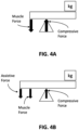
- a wearable assistance device in accordance with the various embodiments is configured to allow a user to selectively reduce the necessary counterbalancing muscle forces. Consequently, the amount of spinal compression is expected to be reduced as well. This is illustrated below with respect to FIGs. 4A and 4B .
- FIGs. 4A and 4B show, respectively, diagrams of the compressive force pushing against a lumbar spine without muscle force assistance for the lower back and with muscle force assistance for the lower back.
- FIG. 4A shows that without any assistance, the muscle force exerts all its force on a moment very close to the lumbar spine, similar to the scenario discussed above with respect to FIG. 1 .
- a high compressive force on the spine is generated to counterbalance the muscle forces.
- muscle force assistance is provided for the lower back in parallel with the normal muscle forces, a more favorable result is obtained. This is illustrated in FIG. 4B .
- FIG. 5 shows how applying an external assistive force parallel with lower back musculature and connective tissue can provide an assistive extensor moment.
- Such an external assistive force reduces spinal disc and muscle forces by effectively increasing the extensor moment arm about the vertebrae/discs. Namely, the assistive force is provided outside the body. The assistive force provides a larger extensor moment arm compared to that for the muscle forces. The assistive force effectively provides an equivalent moment with a smaller force which reduces the resultant spinal compression force.
- ⁇ r represents the added distance to the moment arm from an elastic band or similar mechanical element, according to an embodiment of the present disclosure.
- the elastic band shown in FIG. 5 stretches during leaning and lifting activity of the wearer to offload lumbar extensors. However, the restorative force of the elastic band supplies an assistive force with the larger extensor moment.
- the various embodiments leverage the foregoing concepts to provide a wearable assistance device that reduces spinal disc and muscle forces by effectively increasing the extensor moment arm about the vertebrae/discs. Moreover, the various embodiments allow the person using the wearable assistance device to selectively adjust the amount of assistance (i.e., the amount of assistive force) needed by engaging and disengaging at least one elastic member. In this way, during a lifting or leaning task, the device can be adjusted to provide strong assistance but remain comfortable for non-lifting or non-leaning tasks. In particular, by providing weak or no assistance, the device is flexible and allows freer motion by the user for everyday tasks. An exemplary configuration of such a wearable assistance device is shown in FIG. 6A-6C .
- FIG. 6A-6C shows an exemplary wearable assistance device 600 in accordance with the various embodiments.
- FIG. 6A shows a side view of the wearable assistance device 600.
- FIG. 6B shows a front view of the wearable assistance device 600.
- FIG. 6C shows a rear view of the wearable assistance device.
- the wearable assistance device 600 includes an upper-body interface 602, a lower-body interface 604, one or more elastic members 606, and a clutch 608.
- the wearable assistance device 600 can optionally include a processor 610. Each of these components will be discussed in greater detail below.
- the upper-body interface 602 can be a garment configured as a vest which can be put on and taken off by a user.
- the interface can be put on and taken off through the use of a zipper, buttons, snaps, straps, or any other type of fasteners for garments.
- the upper-body interface is configured as a vest that contains holes for the wearer's arms and head while extending roughly halfway down on the wearer's torso.
- the vest is configured to bear the weight of a load carried by the wearer and to distribute force over the wearer's shoulders, back, and chest. Additional loading is directed through the elastic members 606 down to the lower-body interface 604.
- the lower-body interface 604 can also be a garment that can be put on and off by the user.
- the lower-body interface 604 is configured as a pair of shorts which can be pulled on and off by the user.
- the pair of shorts cover the majority of the wearer's thighs and distribute pressure over the surface area of the shorts.
- the shorts can be made of an elastic material that adapts and conforms to the wearer's thighs, thus ensuring a good fit.
- straps, lacing, or other securing elements can be provided in the shorts to ensure that the shorts do not run up the user's thighs when the wearable assistance device 600 is in use.
- the lower body interface includes a securing mechanism 612 for each thigh.
- FIG. 6D shows how the applied forces are distributed through the upper-body 602 and lower-body 604 interfaces when a user dons the wearable assistance device 600.
- the upper-body interface is configured to distribute forces not only along the back of the user, but also along the sides of torso of the user. Thus, forces are not distributed solely along the user's back when performing tasks. These forces are then transferred to the lower-body interface, as shown by arrow 654.
- FIG. 10A also shows how the thigh interfaces are designed with a taper 656 which prevents the interfaces from sliding up the thigh during use. This taper conforms to the typical, conical shape of the thigh.
- the upper-body interface 602 and the lower-body interface 604 are connected via one or more elastic member 606 to allow forces to be transferred from the upper-body interface 602 to the lower-body interface 604.
- two elastic members 606 are configured to couple the vest defining the upper-body interface 602 and the shorts defining the lower body interface 604 by extending from the back of the vest to the back of the pair of shorts in parallel with the back of the user.
- the exemplary embodiment of wearable assistance device 600 includes a pair of elastic members 606 and respective clutches 608. As shown in FIG. 6C , these are provided in an overlapping arrangement. Such an arrangement lowers the probability that the elastic members will become entangled. However, the various embodiments are not limited to any particular number of arrangement of elastic member and clutches.
- the first elastic portion 606A is configured to have a low stiffness and the second elastic portion 606B is configured to have a high stiffness.
- These elastic portions 606A and 606B are connected in series.
- the elastic member 606 is, in turn, configured to pass through clutch 608 so as to allow clutch 608 to selectively adjust a stiffness of the resulting spring between upper-body interface 602 and lower-body interface 604.
- the amount of assistive force provided by the elastic member 606 is also adjusted. This is schematically illustrated with respect to FIG. 7A-7C .
- a clutch mechanism is integrated into the wearable assistance device so that wearer can selectively engage and disengage the elastic assistance.
- Wearers are typically not performing leaning or lifting tasks 100% of the time, so a clutch allows wearers to 'turn off the elastic assistance when it is not needed. For example, a wearer typically does not need elastic assistance during walking or sitting down. In such scenarios, the wearer can then 'turn on' the elastic assistance when it is needed without the need to take on or off the entire device.
- FIGs. 7A-7C shows the configuration and operation of clutch mechanism in accordance with the various embodiments.
- the clutch can be an electromechanical or mechanical mechanism configured to operate with an elastic member, such as elastic member 606 in FIG. 6A-6C , to selectively adjust the amount of assistance to be provided.
- FIG. 7A schematically illustrates the arrangement and operation of the clutch mechanism and the elastic member in accordance with an embodiment.
- an elastic member with two elastic portions can be modeled as a series arrangement of two springs to provide forces in parallel with the lower back during leaning or lifting activities.
- one spring (labeled K1 in FIG. 7A ) can be connected to the person's trunk (via an upper-body interface).
- a second spring (labeled K2 in FIG. 7A ) can be relatively stiffer or stronger that the first spring and can be connected to the person's thigh (via a lower-body interface).
- the assistive force of each of the springs will be essentially the amount of restorative force generated by each of these springs when they are stretched or otherwise deformed.
- the clutch can be disengaged.
- the elastic member that connects the upper-body interface to the lower-body interface i.e., the series combination of K1 and K2
- the weaker spring (K1) deforms first in response to leaning or lifting. This is illustrated in FIG. 7B by the stretching of K1.
- K1 has a lower stiffness and K2 does not deform, the overall restorative force will be relatively low. As a result, little or no assistive force is provided when leaning or lifting with the clutch disengaged.
- a disengaged clutch allows a wearer to move, bend, and lean with negligible resistance to their movements.
- the weak spring K1 stretches as the wearer leans forward and applies minimal resistance to movement
- the weak spring K1 can be configured so as to provide enough restorative force to keep the elastic member taut. This can help ensure that the upper-body interface, the lower-body interface, and clutch do not fall or protrude from the wearer's back.
- the clutch When assistance is needed, the clutch can be engaged such that the load path between the upper-body interface and the lower-body interface goes only through the stiff spring K2 and not through spring K1.
- the elastic member that connects the upper-body interface to the lower-body interface i.e., the series combination of K1 and K2
- the stiffer spring K2 is fixed at the clutch when the clutch is engaged. This forces the stiff spring K2 to stretch as the wearer leans forward.
- the stiff spring K2 acts in parallel with lower back muscles and its higher stiffness results in a higher restorative force, an assistive force is provided and reduces muscle effort during leaning.
- the stiffnesses of the K1 and K2 can be reversed.
- the location of the clutch mechanism can be changed so that when the clutch mechanism is engaged, the stiffer spring, K1, provides assistive force.
- the clutch mechanism can be located on the lower-body interface instead of the upper body interface.
- the arrangement of the elastic member can be configured so as to provide support when the clutch is disengaged instead of when the clutch is engaged.
- the stiffnesses of K1 and K2 are reversed.
- the clutch is engaged, only the lower stiffness spring is used and little assistance is provided.
- the clutch is disengaged, the combined stiffness is higher, providing some assistance.
- the wearable assistance device can have multiple levels of assistance.
- the elastic member can be defined using two or more elastic members that are configured in parallel.
- any portion of the elastic member can consist of two or more elastic portions that are configured in parallel.
- the clutch mechanism can be configured to engage all of the elastic members (or portions) in parallel to get a higher stiffness, or just some subset of these to get an intermediate stiffness. In this way, the clutching mechanism can support variable levels of spring assistance for different tasks.
- EMG sensors can be integrated into the wearable assistance device along with an automated algorithm that identifies when to engage or disengage assistance based on sensor data.
- an external sensor can be used.
- an EMG sensor 614 can be placed on the user's body.
- the EMG sensor 614 can be communicatively coupled with the processor 610.
- the processor 610 can then, based on an automated algorithm, determine if assistance is required for a user's current activities. For example, when utilizing EMG control, the processor 610 can identify when a wearer might want active assistance instead of passive assistance based on the EMG signal received from the control.
- EMG signals other body dynamic data can be used in the various embodiments.
- force or pressure sensors on the user's body can be used to generate signals indicating when assistance is required.
- pressure or force sensors can be activated during certain types of activities requiring assistance and the corresponding signals can be used to engage the clutch.
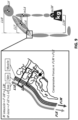
- FIG. 8 shows a side perspective view of a clutch mechanism 800 which includes a friction cam 810 and a base 820.
- the clutch mechanism 800 can be attached to the upper-body interface 830 and a portion of elastic member 840 is fed between the friction cam 810 and the base 820.
- the elastic member 840 can be attached to the upper-body interface 830 on one end and to the lower-body interface 850 on the other end.
- the friction cam 810 and the base 820 are connected via a rotation hinge joint 805.
- the friction cam 810 is disengaged, it is rotated upwards such that the friction cam 810 loses contact with the portion of elastic member 840.
- the elastic member 840 can then slide freely through the clutch mechanism 800. Consequently, forces are transferred between the upper-body interface 830 and the lower-body interface 850 along the entirety of the elastic member 840.
- little or no assistance is provided.
- an actuator can be provided.
- the actuator can be a small electric servomotor and battery located in a front pocket of the upper-body interface.
- a Bowden cable can be looped from the front pocket, over the shoulder to the wearer's mid-back, where a friction cam is located.
- the Bowden cable transmits motor motion into motion along the cable, which causes the clutch to engage or disengage.
- the Bowden cable alternatively could go between the clutch and an actuator in any other method.
- the actuator alternatively can be located anywhere else on the wearable assistance device besides in a front pocket of the upper-body interface.
- actuation of the clutch mechanism is not limited to Bowden cables. Rather, any mechanism for engaging or disengaging a clutch mechanism can be used in the various embodiments.
- FIG. 9 is an anatomical diagram illustrating the reduction in compressive forces when a wearable assistance device in accordance with the various embodiments is used.
- both the assistance device and the lower back muscles contribute to a downward force against the lumbar spine.
- the compressive force must equal the sum of the muscle force and the assistance device force. This can be contrasted with FIG. 3 where the muscle force had to entirely respond to the compressive force.
- the counterbalancing muscle moment equals the cross product of compressive forces ( F ⁇ M ) and the distance from the lumbar spine moment to the center of mass for the person and the carried load ( L ⁇ M ).
- the assistance device moment equals the cross product of compressive forces of the assistance device and the distance from the assistance device to the person's center of mass. If the low back extensor moment was provided entirely by muscle, then the resultant compressive force on the spinal disc would be larger than if the moment resulted in part or in whole by the wearable assistance device. This is a mechanical consequence of the spring provided by the assistance device having a larger moment arm about the lumbar spine than the muscles.
- FIG. 10B estimates the compressive force acting on the S1 and L5 vertebrae in the wearer's spine. As shown by the XY-plot, the compressive forces acting on the S1 and L5 vertebrae are estimated to be lower with the wearable assistance device ("w/ Exo") as opposed to without it (“w/o Exo”). This shows that the wearer has reduced spine compression when wearing a wearable assistance device according to the various embodiments as opposed to without it.
- FIG. 11A shows the effects with a wearable assistance device according to the various embodiments ("With") and without such a device ("Without”) during leaning and lifting tasks reduced EMG activity in the erector spinae.
- Mean EMG activity was collected from testing seven healthy subjects performing leaning and lifting tasks with and without a wearable assistance device according to the various embodiments. Subjects leaned forward at pre-determined angles while holding a 4.5 kilogram (kg) weight to their sternum. Mean EMG activity was computed by averaging the left and right erector spinae EMG and calculating an averaged time series signal over the middle 20 seconds of the trial in which the subjects were statically leaning.
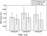
- FIG. 11B shows the amount of support provided with a wearable assistance device according to the various embodiments ("With Exo") and without such a device ("Without Exo").
- the trunk angle graphs (row i) show what angle the wearer is leaning at when each set of data is measured.
- the Exo Force graphs (row ii) show the amount of force a wearable assistance device according to the various embodiments provides when leaning at various angles.
- the EMG activity graphs (row iii) shows that the wearer has greater EMG activity when not wearing the wearable assistance device according to the various embodiments.
- the Spine Force graphs in (row iv) show that at the three measured leaning angles of 30-degrees, 60-degrees, and 90-degrees, the wearer was estimated to incur a greater spine force when not wearing a wearable assistance device according to the various embodiments.
- FIG. 12 shows the average erector spinae EMG activity for an individual during lifting of a 12,7 kg (28 lb) weight versus time (normalized to 1000 data points to represent lifting cycle).
- the results show reduced EMG activity of the low back muscles while using a wearable assistance device ("with exo") according to an embodiment of the invention as compared to not using any assistance device (“without exo”).
- FIG. 13 shows the average erector spinae EMG activity for an individual during lifting of a 24 kg (53 lb) weight versus time (normalized to 1000 data points to represent lifting cycle).
- the results show reduced EMG activity of the low back muscles while using a wearable assistance device ("with exo") according to an embodiment of the invention as compared to not using any assistance device (“without exo”).
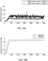
- FIG. 14B shows the moment for the L5 and S1 vertebrae during the same leaning task.
- This graph shows that a wearer with a wearable assistance device according to the various embodiments ("w/ Exo") has a greater moment than without a wearable assistance device (“w/o Exo”).
- w/ Exo wearable assistance device
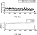
- FIG. 15A shows the EMG percent envelope for a second subject at a static leaning task of between 45 and 60 degrees.
- Subject 2 has a lower EMG percent envelope with a mean at 0.17585 when wearing a wearable assistance device according to the various embodiments ("w/ Exo"). Without the wearable assistance device according to the various embodiments, the same wearer has an EMG percent envelope mean at 0.27304 ("w/o Exo"). This discrepancy shows that the wearer exerts less effort when wearing the wearable assistance device according to the various embodiments.
- FIG. 15B shows the moment for Subject 2's L5 and S1 vertebrae during the same leaning task.
- This graph shows that a wearer with a wearable assistance device according to the various embodiments ("w/ Exo") has a greater moment than without a wearable assistance device (“w/o Exo”).
- w/ Exo wearable assistance device
- FIG. 16A shows the EMG percent envelope for a first subject at a static leaning task of 90 degrees.
- Subject 1 has a lower EMG percent envelope with a mean at 0.15157 when wearing a wearable assistance device according to the various embodiments ("w/ Exo"). Without the wearable assistance device according to the various embodiments, the same wearer has an EMG percent envelope mean at 0.35147 (“w/o Exo"). This discrepancy shows that the wearer exerts less effort when wearing the wearable assistance device according to the various embodiments.
- FIG. 16B shows the moment for Subject 1's L5 and S1 vertebrae during the same leaning task.
- This graph shows that a wearer with a wearable assistance device according to the various embodiments ("w/ Exo") has a greater moment than without a wearable assistance device (“w/o Exo”).
- w/ Exo wearable assistance device
- FIG. 17A shows the EMG percent envelope for a second subject at a static leaning task of 90 degrees.
- Subject 2 has a lower EMG percent with a mean at 0.20274 when wearing a wearable assistance device according to the various embodiments ("w/ Exo"). Without the wearable assistance device according to the various embodiments, the same wearer has an EMG percent envelope at 0.31649 ("w/o Exo"). This discrepancy shows that the wearer exerts less effort when wearing the wearable assistance device according to the various embodiments.
- FIG. 17B shows the moment for Subject 2's L5 and S1 vertebrae during the same leaning task.
- This graph has almost identical moments regardless of whether Subject 2 is wearing a wearable assistance device according to the various embodiments ("w/ Exo") or not ("w/o Exo"). Although this may appear to be inconclusive as to the effect on the wearer, FIG. 17A shows that although Subject 2 has similar moments, Subject 2 still exerts lower effort when wearing a wearable assistance device according to the various embodiments.
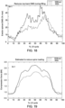
- FIG. 18 shows the EMG activity of the lower back erector spinae muscles during lifting activity averaged over data collected from eight healthy subjects with and without a wearable assistance device according to the various embodiments.
- Lifting trials were parsed into cycles, where a cycle begins with the subject standing upright. The cycle is at 50% when the subject is at the bottom of the lift, and at 100% when the subject is standing upright again. Average lift cycle durations were calculated to ensure that cycle durations remained consistent for different weights.
- FIG. 18 also shows that when a wearer has a wearable assistance device according to the various embodiments, the EMG activity of the erector spinae muscles is lower during periods of high activity than when the wearer does not have a wearable assistance device according to the various embodiments. This suggests that the wearable assistance device according to the various embodiments is successful at reducing strain on reducing on lower back muscles.
- FIG. 19 shows compression force in kilonewtons (kN) during a lift cycle. This was estimated with a simple spine model and paired t-tests to compare the disc loading with or without wearable assistance device according to the various embodiments.
- FIG. 19 shows how a wearer with a wearable assistance device according to the various embodiments has a lower compressive force during the majority of the lift cycle than a wearer would have without such a wearable assistance device.
- FIGs. 20A and 20B shows analysis of mean and peak EMG activity, respectively, for different lifting tasks to compare activity with a wearable assistance device according to the various embodiments versus activity without a wearable assistance device.
- FIG. 20C shows analysis of mean EMG activity for different leaning tasks to compare activity with a wearable assistance device according to the various embodiments versus activity without a wearable assistance device. This data was collected from eight healthy subjects while wearing and not wearing a wearable assistance device according to the various embodiments. By all measures, whether lifting tasks of different weights or leaning tasks of different angles, the wearer has lower EMG activity when wearing a wearable assistance device according to the various embodiments. This provides broad support for the use of wearable assistance device according to the various embodiments to reduce lower back fatigue.
- a wide variety of materials can be used to form the upper and lower-body interfaces of the wearable assistant device discussed above.
- Conventional exoskeletons are made with rigid materials and hard, bulky exteriors. Additionally, many conventional exoskeletons adhere to the person through straps or hard plastic interfaces. This can cause bruising or soft tissue damage to the body area under the straps. This is especially true for the lower-body interface.
- the sleeves defining the lower-body interface can be made from thermoplastic elastomer or silicon and can be custom designed to fit the wearer's exact body type.
- the sleeve could also be made of a stretchable material to fit wearers of different sizes.
- On top of the sleeve can be a semi-rigid or non-rigid fabric cover. The cover attaches to other components of the wearable assistance device while the sleeve functions primarily to protect the wearer's skin and help distribute pressure evenly. Such a configuration is illustrated in FIG. 21 .
- the sleeve of the wearable assistance device can be a thermoplastic elastomer/silicone sleeve with a compressive fabric cover.
- the compressive fabric cover can have one-way stretch or can have selectively stiff portions that are configured to distribute weight evenly.
- FIG. 22 illustrates the wearable assistance device with the upper-body interface 602, the lower-body interface 604, the one or more elastic members 606 that each has a first portion 606A and a second portion 606B, and a clutch 608.
- FIG. 23 shows how the thermoplastic elastomer/silicone sleeve and compressive fabric cover is configured.
- the sleeve conforms around the limb segment and grips the skin to prevent the sleeve from slipping into a different configuration on the limb.
- the sleeve grips the wearer's legs.
- a fabric cover attaches on top of the sleeve and can be attached to the sleeve via Velcro or other means.
- Elastic bands can attach to the fabric cover. External force from the exo-elastic bands can then be applied to the outer cover.
- the combination of the fabric cover and the thermoplastic elastomer/silicone sleeve allows force from the elastic bands to distribute over the surface area of skin so that large forces can be applied without the sleeve slipping from the limb.
- FIG. 24 shows how much displacement different configurations of a lower-body interface provide depending on the force applied.
- the interface will move too much to be operable and effectively fail at approximately 300N. This is shown by curve 2402 in FIG. 24 .
- An exo-interface with the cover/liner only can withstand much higher forces than the standard strap/shell, as shown by curve 2404.
- An exo-interface with both a liner and a skin adhesive such as the thermoplastic elastomer/silicone sleeve discussed above, can withstand force with even less displacement than the exo-interface with just a liner, as shown by curve 2406. Therefore, FIG. 24 shows that a wearable assistance device according to the various embodiments can be configured to can support loads over twice as heavy as the standard strap/shell attachments.
- upper and lower interfaces of a wearable assistance device could be coupled between the wearer's trunk and the wearer's head. This coupling can offload the neck such as to assist a surgeon whose head is tilted forward for long periods during an operation.
- Upper and lower interfaces of a wearable assistance device according to some embodiments can be coupled between the upper and lower arms to offload the bicep muscles. This can be useful for a parent who carries a child on their arm for an extended period of time. Coupling between the shank and the foot can provide assistance to individuals with weak calf muscles. Elastic assistance can be selectively engaged or disengaged with the same clutching mechanism.
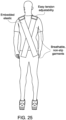
- FIG. 25 shows how the principles discussed herein can be integrated into every day clothing.
- a shirt could have embedded elastic which resists movement during lifting and leaning tasks.
- the shoulder area of the shirt could have tension adjustability or a clutching mechanism that is easily accessible to the wearer.
- Both the shirt and the pants can be made from breathable non-slip garments to allow for force to be distributed across the wearer's body.
- the wearable assistance devices described herein can be designed with a side-to-side differential.
- a wearer leans to the right, or forward and partially to the right the lower left muscles of the back undergo higher strain than muscles on the right side.
- the wearable assistance devices can be designed to naturally accommodate asymmetry to provide support to each side of the lower back when leaning right or left.
- This side-to-side differential can be achieved by crisscrossing the elastic cables along the back.
- the side-to-side differential could also be achieved by adding elastic members along the left and right sides of the user. Side-to-side differential could also be added via other means such as integrating a small pulley or lever mechanism between elastic members.
- the wearable assistance devices described herein can be used to train the abdominal muscles where a wearable assistance device according to the various embodiments could be selectively engaged to resist forward bending movement.
- the stiff elastic member(s) running along the back could be engaged. Users would need to exert sufficient abdominal muscle effort to bend normally plus the additional effort needed to stretch the elastic band. In this way the wearer's abdominal muscles would get an increased workout to help strengthen the person's core.
- a viscous or viscoelastic member can be used.
Landscapes
- Health & Medical Sciences (AREA)
- Life Sciences & Earth Sciences (AREA)
- Engineering & Computer Science (AREA)
- Animal Behavior & Ethology (AREA)
- General Health & Medical Sciences (AREA)
- Public Health (AREA)
- Veterinary Medicine (AREA)
- Biomedical Technology (AREA)
- Heart & Thoracic Surgery (AREA)
- Vascular Medicine (AREA)
- Nursing (AREA)
- Orthopedic Medicine & Surgery (AREA)
- General Engineering & Computer Science (AREA)
- Mechanical Engineering (AREA)
- Epidemiology (AREA)
- Physics & Mathematics (AREA)
- Physical Education & Sports Medicine (AREA)
- Rehabilitation Therapy (AREA)
- Cardiology (AREA)
- Oral & Maxillofacial Surgery (AREA)
- Transplantation (AREA)
- Pain & Pain Management (AREA)
- Biophysics (AREA)
- Pathology (AREA)
- Medical Informatics (AREA)
- Molecular Biology (AREA)
- Surgery (AREA)
- Orthopedics, Nursing, And Contraception (AREA)
- Rehabilitation Tools (AREA)
- Manipulator (AREA)
Claims (10)
- Eine tragbare Assistenzvorrichtung (600) für den unteren Rücken, die von einem Benutzer getragen wird und Folgendes beinhaltet:eine Oberkörperschnittstelle (602) mit einer vorderen und einer hinteren Seite;eine Unterkörperschnittstelle (604) mit einer vorderen Seite und einer hinteren Seite;ein oder mehrere elastische Elemente (606), wobei jedes der elastischen Elemente (606) die Oberkörperschnittstelle (602) mit der Unterkörperschnittstelle (604) mechanisch koppelt und sich von der hinteren Seite der Oberkörperschnittstelle (602) auf die hintere Seite der Unterkörperschnittstelle (604) und entlang eines Rückens des Benutzers erstreckt, um eine Hilfskraft parallel zu dem Rücken des Benutzers bereitzustellen;wobei jedes der elastischen Elemente (606) einen ersten elastischen Abschnitt (606A) und einen zweiten elastischen Abschnitt (606B), die in Reihe geschaltet sind, beinhaltet, wobei der erste elastische Abschnitt (606A) mit der Oberkörperschnittstelle (602) verbunden ist und wobei der zweite elastische Abschnitt (606B) mit der Unterkörperschnittstelle (604) verbunden ist, wobei jeder des ersten elastischen Abschnitts (606A) und des zweiten elastischen Abschnitts (606B) eine unterschiedliche Steife aufweist;dadurch gekennzeichnet, dass sie ferner Folgendes beinhaltet:
einen Kupplungsmechanismus (608), der mit jedem der elastischen Elemente (606) assoziiert ist, wobei der Kupplungsmechanismus (608) konfiguriert ist, um die von dem einen oder den mehreren der elastischen Elemente (606) bereitgestellte Hilfskraft durch selektives In-Eingriff-Bringen und Außer-Eingriff-Bringen mit dem einen der elastischen Elemente (606) an einem Punkt zwischen dem ersten elastischen Abschnitt (606A) und dem zweiten elastischen Abschnitt (606B) selektiv anzupassen. - Assistenzvorrichtung (600) gemäß Anspruch 1, ferner beinhaltend einen Prozessor (610), der zum Empfangen von Körperdynamikdaten und Anpassen des Betriebs des Kupplungsmechanismus (608) basierend auf den Körperdynamikdaten konfiguriert ist.
- Assistenzvorrichtung (600) gemäß Anspruch 1, ferner beinhaltend einen Prozessor (610), der zum Empfangen eines manuellen Eingabesignals und Anpassen des Betriebs des Kupplungsmechanismus (608) basierend auf dem manuellen Eingabesignal konfiguriert ist.
- Assistenzvorrichtung (600) gemäß Anspruch 1, wobei die Oberkörperschnittstelle (602) in der Form einer Weste vorliegt.
- Assistenzvorrichtung (600) gemäß Anspruch 1, wobei die Unterkörperschnittstelle (604) in der Form von Bandagen oder kurzen Hosen vorliegt.
- Assistenzvorrichtung (600) gemäß Anspruch 1, wobei die Steife des zweiten elastischen Abschnitts (606B) größer als die Steife des ersten elastischen Abschnitts (606A) ist.
- Assistenzvorrichtung (600) gemäß Anspruch 1, wobei das eine oder die mehreren elastischen Elemente (606) Folgendes beinhalten:ein erstes elastisches Element, das sich von einer rechten Seite der Oberkörperschnittstelle (602) auf eine linke Seite der Unterkörperschnittstelle (604) erstreckt, undein zweites elastisches Element, das sich von einer linken Seite der Oberkörperschnittstelle (602) auf eine rechte Seite der Unterkörperschnittstelle (604) erstreckt.
- Assistenzvorrichtung (600) gemäß Anspruch 1, wobei der Kupplungsmechanismus (608) mit der Oberkörperschnittstelle (602) mechanisch verbunden ist und wobei der Kupplungsmechanismus (608) zwischen dem ersten elastischen Abschnitt (606A) und dem zweiten elastischen Abschnitt (606B) positioniert ist.
- Ein Verfahren zum Betreiben einer tragbaren Assistenzvorrichtung (600), die Folgendes aufweist: eine Oberkörperschnittstelle (602) mit einer vorderen Seite und einer hinteren Seite, eine Unterkörperschnittstelle (604) mit einer vorderen Seite und einer hinteren Seite, ein oder mehrere elastische Elemente (606), die die Oberkörperschnittstelle (602) mit der Unterkörperschnittstelle (604) koppeln und sich von der hinteren Seite der Oberkörperschnittstelle (602) auf die hintere Seite der Unterkörperschnittstelle (604) und entlang eines Rückens des Benutzers erstrecken, um eine Hilfskraft parallel zu dem Rücken des Benutzers bereitzustellen,wobei jedes der elastischen Elemente (606) einen ersten elastischen Abschnitt (606A) und einen zweiten elastischen Abschnitt (606B), die in Reihe geschaltet sind, beinhaltet, wobei der erste elastische Abschnitt (606A) mit der Oberkörperschnittstelle (602) verbunden ist und wobei der zweite elastische Abschnitt (606B) mit der Unterkörperschnittstelle (604) verbunden ist, wobei jeder des ersten elastischen Abschnitts (606A) und des zweiten elastischen Abschnitts (606B) eine unterschiedliche Steife aufweist; undeinen Kupplungsmechanismus (608), der mit jedem der elastischen Elemente (606) assoziiert ist, wobei das Verfahren Folgendes beinhaltet:Bestimmen, über einen Prozessor (610), ob eine gegenwärtige Aktivität des Benutzers eine Hilfskraft benötigt; undbeim Bestimmen, dass die gegenwärtige Aktivität eine Hilfskraft benötigt, Erzeugen, über den Prozessor (610), von Steuerungssignalen für den Kupplungsmechanismus (608), die bewirken, dass der Kupplungsmechanismus (608) durch selektives In-Eingriff-Bringen und Außer-Eingriff-Bringen mit dem einen der elastischen Elemente (606) an einem Punkt zwischen dem ersten elastischen Abschnitt (606A) und dem zweiten elastischen Abschnitt (606B) die Hilfskraft, die über ein assoziiertes Element der elastischen Elemente (606) bereitgestellt wird, erhöht.
- Verfahren gemäß Anspruch 9, das ferner Folgendes beinhaltet:
beim Bestimmen, dass die gegenwärtige Aktivität keine Hilfskraft benötigt, Erzeugen, über den Prozessor (610), von Steuerungssignalen für den kraftbetriebenen Kupplungsmechanismus (608), wobei die Steuerungssignale konfiguriert sind, um die Hilfskraft zu verringern, die über ein assoziiertes Element der elastischen Elemente (606) bereitgestellt wird.
Priority Applications (1)
| Application Number | Priority Date | Filing Date | Title |
|---|---|---|---|
| EP24192166.7A EP4431759A3 (de) | 2017-01-19 | 2018-01-19 | Tragbare assistenzvorrichtungen und verfahren zum betrieb |
Applications Claiming Priority (2)
| Application Number | Priority Date | Filing Date | Title |
|---|---|---|---|
| US201762448104P | 2017-01-19 | 2017-01-19 | |
| PCT/US2018/014393 WO2018136722A1 (en) | 2017-01-19 | 2018-01-19 | Wearable assistance devices and methods of operation |
Related Child Applications (2)
| Application Number | Title | Priority Date | Filing Date |
|---|---|---|---|
| EP24192166.7A Division EP4431759A3 (de) | 2017-01-19 | 2018-01-19 | Tragbare assistenzvorrichtungen und verfahren zum betrieb |
| EP24192166.7A Division-Into EP4431759A3 (de) | 2017-01-19 | 2018-01-19 | Tragbare assistenzvorrichtungen und verfahren zum betrieb |
Publications (3)
| Publication Number | Publication Date |
|---|---|
| EP3571018A1 EP3571018A1 (de) | 2019-11-27 |
| EP3571018A4 EP3571018A4 (de) | 2020-09-02 |
| EP3571018B1 true EP3571018B1 (de) | 2024-10-02 |
Family
ID=62908983
Family Applications (2)
| Application Number | Title | Priority Date | Filing Date |
|---|---|---|---|
| EP18741272.1A Active EP3571018B1 (de) | 2017-01-19 | 2018-01-19 | Tragbare assistenzvorrichtungen und verfahren zum betrieb |
| EP24192166.7A Pending EP4431759A3 (de) | 2017-01-19 | 2018-01-19 | Tragbare assistenzvorrichtungen und verfahren zum betrieb |
Family Applications After (1)
| Application Number | Title | Priority Date | Filing Date |
|---|---|---|---|
| EP24192166.7A Pending EP4431759A3 (de) | 2017-01-19 | 2018-01-19 | Tragbare assistenzvorrichtungen und verfahren zum betrieb |
Country Status (5)
| Country | Link |
|---|---|
| US (1) | US11980563B2 (de) |
| EP (2) | EP3571018B1 (de) |
| CA (1) | CA3054158A1 (de) |
| ES (1) | ES2993742T3 (de) |
| WO (1) | WO2018136722A1 (de) |
Families Citing this family (14)
| Publication number | Priority date | Publication date | Assignee | Title |
|---|---|---|---|---|
| EP3571018B1 (de) | 2017-01-19 | 2024-10-02 | Vanderbilt University | Tragbare assistenzvorrichtungen und verfahren zum betrieb |
| CN112004511B (zh) * | 2018-02-17 | 2024-05-28 | 哈佛学院院长及董事 | 用于预防肌肉骨骼损伤和增强性能的可穿戴设备 |
| EP3738464B1 (de) | 2019-05-17 | 2023-07-05 | ETH Zürich | Körperstützvorrichtung, deren verwendung und verfahren zur handhabung von lasten |
| AU2020284017B2 (en) * | 2019-05-28 | 2025-02-27 | Vanderbilt University | Wearable assistance devices and methods of operation |
| EP3975945A4 (de) * | 2019-05-28 | 2023-06-28 | Vanderbilt University | Momentarmerweiterungssystem für ein exoskelett |
| DE102019130389B4 (de) * | 2019-11-11 | 2022-12-29 | Ottobock Se & Co. Kgaa | Vorrichtung zum unterstützen eines rückens eines benutzers |
| EP4120967A4 (de) * | 2020-03-16 | 2024-04-17 | Vanderbilt University | Exoskelett mit verstellbaren modularen riemen und bändern |
| EP3904013B1 (de) * | 2020-04-27 | 2022-07-20 | C.R.F. Società Consortile per Azioni | System zur unterstützung eines bedieners an einer arbeitsstation |
| WO2021257671A1 (en) * | 2020-06-16 | 2021-12-23 | Vanderbilt University | Bimodal exosuit |
| US11737945B2 (en) * | 2020-10-15 | 2023-08-29 | Yong Tai Global Co., Ltd. | Wrist joint actuating structure of hand rehabilitation device |
| KR20220069649A (ko) | 2020-11-20 | 2022-05-27 | 현대자동차주식회사 | 근력 보조 장치 |
| US20230338222A1 (en) * | 2022-04-25 | 2023-10-26 | Vanderbilt University | Self-balancing harness for wearable assistance devices |
| AU2024231631A1 (en) * | 2023-03-07 | 2025-09-25 | Herowear Llc | Body conforming interfaces for wearable assistance device |
| AU2024238386A1 (en) * | 2023-03-07 | 2025-09-18 | Vanderbilt University | Wearable assistance device with offset features |
Family Cites Families (64)
| Publication number | Priority date | Publication date | Assignee | Title |
|---|---|---|---|---|
| US596839A (en) | 1898-01-04 | Back and shoulder brace | ||
| US330213A (en) * | 1885-11-10 | Hitching-strap clamp | ||
| US1098492A (en) | 1913-05-21 | 1914-06-02 | George W Gibson | Back-brace. |
| US1386067A (en) | 1920-06-09 | 1921-08-02 | Mason Mayor | Shoulder and body brace |
| US1553874A (en) * | 1923-04-17 | 1925-09-15 | Nivens James Harvey | Elastic-rubber back support |
| US4709692A (en) | 1986-07-02 | 1987-12-01 | Kirschenberg Bruce H | Thigh mounted lower back support belt |
| US5256135A (en) | 1992-01-23 | 1993-10-26 | Medisol U.S.A., Inc. | Thoracic-lumbar-sacral corrective orthosis ("TLSO") corrective back supporting brace and chair side support buttress |
| RU2054907C1 (ru) | 1992-01-31 | 1996-02-27 | Акционерное Общество Закрытого Типа "Аюрведа" | Устройство для лечения больных с нарушением позы и двигательной активности |
| DE4419260C2 (de) | 1994-06-01 | 1996-09-05 | Bauerfeind Gmbh | Schlauchförmige Bandage für menschliche Körperteile |
| US5716307A (en) * | 1996-07-08 | 1998-02-10 | Vadher; Dinesh L. | Body exercise device |
| US5709648A (en) | 1996-09-18 | 1998-01-20 | Joseph Walter Webb | Resilient back support device |
| US5816251A (en) * | 1997-10-17 | 1998-10-06 | Glisan; Billy Joe | Back support system |
| US6190342B1 (en) | 1998-02-03 | 2001-02-20 | Earl J. Taylor | Taylor harness |
| US6129691A (en) | 1999-03-24 | 2000-10-10 | Ruppert; John F. | Pliant back support apparatus with foot engagements |
| US6450131B1 (en) | 2001-06-18 | 2002-09-17 | Daniel James Broman | Forward bending motion control harness |
| EP1737542A4 (de) | 2003-12-15 | 2010-03-31 | Univ Kingston | Vorrichtung und verfahren zur aufrichthilfe |
| DE102004009315B4 (de) | 2004-02-26 | 2007-10-31 | Matthias Dr. Soyka | Vorrichtung zur Entlastung des Rückens |
| US7237799B2 (en) * | 2004-06-01 | 2007-07-03 | Autoliv Asp, Inc | Seat belt system |
| DE202005011650U1 (de) | 2005-07-15 | 2006-11-23 | Ferd. Hauber Gmbh & Co. Kg | Rückenorthese |
| US7446326B2 (en) | 2005-08-31 | 2008-11-04 | Varian Semiconductor Equipment Associates, Inc. | Technique for improving ion implanter productivity |
| JP4345025B2 (ja) * | 2006-09-12 | 2009-10-14 | 国立大学法人 北海道大学 | 筋力補助装置 |
| US8128584B2 (en) | 2007-04-09 | 2012-03-06 | Tyco Healthcare Group Lp | Compression device with S-shaped bladder |
| US8066654B2 (en) | 2007-07-31 | 2011-11-29 | Orthomerica Products, Inc. | Adjustable extension compression posterior spinal orthosis and method |
| TWM330826U (en) | 2007-11-07 | 2008-04-21 | Kao Chen Entpr Co Ltd | Pull string adjusting type waist-protecting restraint belt |
| US20090255531A1 (en) | 2008-01-07 | 2009-10-15 | Johnson Douglas E | Portable system for assisting body movement |
| US8088088B2 (en) | 2008-11-19 | 2012-01-03 | Patrick Timothy Hurley | Back support system |
| EP2484317B1 (de) | 2009-09-28 | 2019-05-22 | Tokyo University Of Science Educational Foundation Administrative Organization | Lumbale stützvorrichtung |
| US8568344B2 (en) | 2009-10-23 | 2013-10-29 | Applied Neural Mechanics, Llc | Torso assist orthotic device |
| US20140100501A1 (en) | 2009-12-22 | 2014-04-10 | Aspen Medical Partners, Llc | Hyperextension Brace |
| US8241090B2 (en) | 2010-02-01 | 2012-08-14 | Jannet Rosello Michael | Bra strap holder |
| US20110237993A1 (en) | 2010-03-29 | 2011-09-29 | Patricia Kirk | Posture strap and method of using same |
| WO2012099709A2 (en) * | 2011-01-20 | 2012-07-26 | Nothwestern University | Further improvements to ankle-foot prosthesis and orthosis capable of automatic adaptation to sloped walking surfaces and methods of use |
| US9022956B2 (en) | 2011-06-10 | 2015-05-05 | U.S. Bionics, Inc. | Trunk supporting exoskeleton and method of use |
| US8832863B2 (en) | 2011-12-27 | 2014-09-16 | Jae Young Yang | Sports taping tights |
| JP5887671B2 (ja) * | 2012-01-16 | 2016-03-16 | 地方独立行政法人北海道立総合研究機構 | 前屈作業補助用具 |
| US9682005B2 (en) * | 2012-02-24 | 2017-06-20 | Massachusetts Institute Of Technology | Elastic element exoskeleton and method of using same |
| ITVR20120076A1 (it) | 2012-04-20 | 2013-10-21 | Fgp Srl | Sistema di tensionamento per supporti ortopedici dorsali per colonna vertebrale |
| JP2015529574A (ja) | 2012-09-17 | 2015-10-08 | プレジデント アンド フェローズ オブ ハーバード カレッジ | 人間動作を補助するための軟性外骨格スーツ |
| US10357391B2 (en) | 2013-01-24 | 2019-07-23 | Ossur Hf | Orthopedic device for treating complications of the hip |
| JP6158414B2 (ja) * | 2013-03-15 | 2017-07-05 | エスアールアイ インターナショナルSRI International | 外骨格スーツ |
| JP6466420B2 (ja) * | 2013-05-31 | 2019-02-06 | プレジデント アンド フェローズ オブ ハーバード カレッジ | 人間動作を補助するための軟性外骨格スーツ |
| ES2732661T3 (es) | 2013-09-20 | 2019-11-25 | Laevo B V | Estructura de soporte ponible y método de soporte del torso |
| KR20160098354A (ko) * | 2013-12-09 | 2016-08-18 | 프레지던트 앤드 펠로우즈 오브 하바드 칼리지 | 보조 가요성 수트들, 가요성 수트 시스템들, 및 사람의 이동을 돕기 위해 이들을 만들고 제어하는 방법들 |
| NZ724905A (en) | 2014-03-07 | 2017-06-30 | Aspen Medical Partners Llc | Brace having elastic and inelastic portions |
| EP3128963A4 (de) * | 2014-04-10 | 2017-12-06 | President and Fellows of Harvard College | Orthopädische vorrichtung mit vorstehenden elementen |
| US10456316B2 (en) | 2014-06-13 | 2019-10-29 | Worcester Polytechnic Institute | Actuators and methods of use |
| SG11201700959PA (en) | 2014-08-08 | 2017-03-30 | Panasonic Corp | Movement assistance device |
| KR101637678B1 (ko) | 2014-09-12 | 2016-07-08 | 서울대학교산학협력단 | 근력 보조장치 |
| JP6385242B2 (ja) * | 2014-10-28 | 2018-09-05 | 株式会社モリタホールディングス | 圧迫回避機能付き腰部負担軽減具 |
| NL2014451B1 (en) | 2015-03-13 | 2016-10-14 | Laevo B V | Wearable support structure for at least partly relieving a human body during leaning or bending over. |
| DE102015208125A1 (de) * | 2015-04-30 | 2016-11-03 | Technische Universität München | Stützsystem für den menschlichen Bewegungsapparat |
| EP3324898B1 (de) | 2015-07-17 | 2021-03-03 | Ekso Bionics, Inc. | Universelle tensegrity-gelenke für menschliches exoskelett |
| US10166426B2 (en) | 2015-08-15 | 2019-01-01 | Olugbenga Peter Adeeko, JR. | Exercise apparatus |
| US11076974B2 (en) | 2016-04-01 | 2021-08-03 | Ing Source, Inc. | Orthotic ankle garment, and method for stabilizing the lower leg of a wearer |
| US10772785B2 (en) | 2016-10-03 | 2020-09-15 | Springactive, Inc. | Personal augmentation suit and method for assisted human motion |
| EP3563577A1 (de) | 2016-12-27 | 2019-11-06 | Koninklijke KPN N.V. | Identifizierung von benutzervorrichtungen zur teilnahme an einem medienrundfunk |
| EP3342390A1 (de) | 2016-12-29 | 2018-07-04 | ETH Zurich | Vorrichtung zur unterstützung eines glieds eines benutzers gegen schwerkraft |
| KR101801868B1 (ko) | 2017-01-02 | 2017-11-27 | 강선영 | 척추측만증 보조기 |
| EP3571018B1 (de) | 2017-01-19 | 2024-10-02 | Vanderbilt University | Tragbare assistenzvorrichtungen und verfahren zum betrieb |
| KR20200024371A (ko) | 2017-05-25 | 2020-03-06 | 유.에스. 바이오닉스, 인크. | 외골격 장치용 조정 가능한 몸통 및 엉덩이 조립체 |
| DE102017112436B4 (de) | 2017-06-06 | 2019-05-29 | Ottobock Se & Co. Kgaa | Vorrichtung zum Unterstützen wenigstens eines Armes eines Benutzers |
| US10245173B2 (en) | 2017-07-11 | 2019-04-02 | Posture Newmatic Technologies, LLC | Method and system for relieving and preventing excessive back and joint discomfort, poor posture, and lack of energy |
| CN112004511B (zh) | 2018-02-17 | 2024-05-28 | 哈佛学院院长及董事 | 用于预防肌肉骨骼损伤和增强性能的可穿戴设备 |
| JP2021528174A (ja) | 2018-06-18 | 2021-10-21 | モべオ・ソシエタ・ア・レスポンサビリタ・リミタータMoveo Srl | 移動補助のためのシステムおよび装置 |
-
2018
- 2018-01-19 EP EP18741272.1A patent/EP3571018B1/de active Active
- 2018-01-19 WO PCT/US2018/014393 patent/WO2018136722A1/en not_active Ceased
- 2018-01-19 CA CA3054158A patent/CA3054158A1/en active Pending
- 2018-01-19 EP EP24192166.7A patent/EP4431759A3/de active Pending
- 2018-01-19 US US16/478,310 patent/US11980563B2/en active Active
- 2018-01-19 ES ES18741272T patent/ES2993742T3/es active Active
Also Published As
| Publication number | Publication date |
|---|---|
| CA3054158A1 (en) | 2018-07-26 |
| EP4431759A3 (de) | 2024-12-18 |
| US11980563B2 (en) | 2024-05-14 |
| EP3571018A1 (de) | 2019-11-27 |
| EP4431759A2 (de) | 2024-09-18 |
| WO2018136722A1 (en) | 2018-07-26 |
| ES2993742T3 (en) | 2025-01-08 |
| US20190358074A1 (en) | 2019-11-28 |
| EP3571018A4 (de) | 2020-09-02 |
Similar Documents
| Publication | Publication Date | Title |
|---|---|---|
| EP3571018B1 (de) | Tragbare assistenzvorrichtungen und verfahren zum betrieb | |
| US12263585B2 (en) | Systems and methods for assistive exosuit system | |
| US20250367016A1 (en) | Wearable assistance devices and methods of operation | |
| US12070406B2 (en) | Patch systems for use with assistive exosuit | |
| KR102617942B1 (ko) | 연질 웨어러블 근육 보조 장치 | |
| US11406285B2 (en) | Exosuit systems and methods for posture session segmentation and biomechanical feedback | |
| US20210275856A1 (en) | Exosuit system systems and methods for assisting, resisting and aligning core biomechanical functions | |
| EP3518857B1 (de) | Persönlicher augmentationsanzug und verfahren zur unterstützten menschlichen bewegung | |
| Lamers et al. | Design, modeling, and demonstration of a new dual-mode back-assist exosuit with extension mechanism | |
| US20190374161A1 (en) | Exosuit systems and methods for detecting and analyzing lifting and bending | |
| US11826298B2 (en) | Preloaded personal augmentation suit and method for assisted human motion | |
| US11478920B2 (en) | Exosuit systems with lumbar and core support | |
| US20230100371A1 (en) | Exosuit having adjustable modular straps and bands | |
| JP2020512039A (ja) | 補助外装スーツと共に使用するパッチシステム | |
| US20240016647A1 (en) | Wearable assistance devices and methods of operation | |
| US12138785B2 (en) | Moment arm extension system for exosuit | |
| US20240157544A1 (en) | Oversuit with static position support | |
| Olson et al. | DEVELOPMENT OF THE PASSIVE LOAD CARRYING PULLEY SUIT |
Legal Events
| Date | Code | Title | Description |
|---|---|---|---|
| STAA | Information on the status of an ep patent application or granted ep patent |
Free format text: STATUS: THE INTERNATIONAL PUBLICATION HAS BEEN MADE |
|
| PUAI | Public reference made under article 153(3) epc to a published international application that has entered the european phase |
Free format text: ORIGINAL CODE: 0009012 |
|
| STAA | Information on the status of an ep patent application or granted ep patent |
Free format text: STATUS: REQUEST FOR EXAMINATION WAS MADE |
|
| 17P | Request for examination filed |
Effective date: 20190816 |
|
| AK | Designated contracting states |
Kind code of ref document: A1 Designated state(s): AL AT BE BG CH CY CZ DE DK EE ES FI FR GB GR HR HU IE IS IT LI LT LU LV MC MK MT NL NO PL PT RO RS SE SI SK SM TR |
|
| AX | Request for extension of the european patent |
Extension state: BA ME |
|
| RIN1 | Information on inventor provided before grant (corrected) |
Inventor name: HOWSER, DUSTIN Inventor name: LAMERS, ERIK Inventor name: YANDELL, MATTHEW Inventor name: ZELIK, KARL |
|
| DAV | Request for validation of the european patent (deleted) | ||
| DAX | Request for extension of the european patent (deleted) | ||
| A4 | Supplementary search report drawn up and despatched |
Effective date: 20200731 |
|
| RIC1 | Information provided on ipc code assigned before grant |
Ipc: A61F 5/02 20060101ALN20200727BHEP Ipc: A61H 1/02 20060101ALN20200727BHEP Ipc: A63B 21/00 20060101ALN20200727BHEP Ipc: A61F 5/01 20060101ALN20200727BHEP Ipc: A61G 5/14 20060101ALN20200727BHEP Ipc: A61B 5/00 20060101ALN20200727BHEP Ipc: A61H 3/00 20060101ALN20200727BHEP Ipc: A61B 5/0488 20060101ALN20200727BHEP Ipc: B25J 9/00 20060101AFI20200727BHEP Ipc: A61F 2/30 20060101ALN20200727BHEP Ipc: A61B 5/04 20060101ALN20200727BHEP Ipc: F16D 13/00 20060101ALI20200727BHEP Ipc: A61F 2/72 20060101ALN20200727BHEP |
|
| REG | Reference to a national code |
Ref country code: HK Ref legal event code: DE Ref document number: 40017971 Country of ref document: HK |
|
| STAA | Information on the status of an ep patent application or granted ep patent |
Free format text: STATUS: EXAMINATION IS IN PROGRESS |
|
| 17Q | First examination report despatched |
Effective date: 20220708 |
|
| P01 | Opt-out of the competence of the unified patent court (upc) registered |
Effective date: 20230607 |
|
| GRAP | Despatch of communication of intention to grant a patent |
Free format text: ORIGINAL CODE: EPIDOSNIGR1 |
|
| STAA | Information on the status of an ep patent application or granted ep patent |
Free format text: STATUS: GRANT OF PATENT IS INTENDED |
|
| RIC1 | Information provided on ipc code assigned before grant |
Ipc: A63B 21/00 20060101ALN20240402BHEP Ipc: A61H 3/00 20060101ALN20240402BHEP Ipc: A61H 1/02 20060101ALN20240402BHEP Ipc: A61G 5/14 20060101ALN20240402BHEP Ipc: A61F 5/01 20060101ALN20240402BHEP Ipc: A61F 2/30 20060101ALN20240402BHEP Ipc: A61F 5/02 20060101ALN20240402BHEP Ipc: A61F 2/72 20060101ALN20240402BHEP Ipc: A61B 5/00 20060101ALN20240402BHEP Ipc: F16D 13/00 20060101ALI20240402BHEP Ipc: B25J 9/00 20060101AFI20240402BHEP |
|
| RIC1 | Information provided on ipc code assigned before grant |
Ipc: A63B 21/00 20060101ALN20240409BHEP Ipc: A61H 3/00 20060101ALN20240409BHEP Ipc: A61H 1/02 20060101ALN20240409BHEP Ipc: A61G 5/14 20060101ALN20240409BHEP Ipc: A61F 5/01 20060101ALN20240409BHEP Ipc: A61F 2/30 20060101ALN20240409BHEP Ipc: A61F 5/02 20060101ALN20240409BHEP Ipc: A61F 2/72 20060101ALN20240409BHEP Ipc: A61B 5/00 20060101ALN20240409BHEP Ipc: F16D 13/00 20060101ALI20240409BHEP Ipc: B25J 9/00 20060101AFI20240409BHEP |
|
| INTG | Intention to grant announced |
Effective date: 20240426 |
|
| RIN1 | Information on inventor provided before grant (corrected) |
Inventor name: LAMERS, ERIK Inventor name: HOWSER, DUSTIN Inventor name: YANDELL, MATTHEW Inventor name: ZELIK, KARL |
|
| GRAS | Grant fee paid |
Free format text: ORIGINAL CODE: EPIDOSNIGR3 |
|
| GRAA | (expected) grant |
Free format text: ORIGINAL CODE: 0009210 |
|
| STAA | Information on the status of an ep patent application or granted ep patent |
Free format text: STATUS: THE PATENT HAS BEEN GRANTED |
|
| AK | Designated contracting states |
Kind code of ref document: B1 Designated state(s): AL AT BE BG CH CY CZ DE DK EE ES FI FR GB GR HR HU IE IS IT LI LT LU LV MC MK MT NL NO PL PT RO RS SE SI SK SM TR |
|
| REG | Reference to a national code |
Ref country code: GB Ref legal event code: FG4D |
|
| REG | Reference to a national code |
Ref country code: CH Ref legal event code: EP |
|
| REG | Reference to a national code |
Ref country code: IE Ref legal event code: FG4D |
|
| REG | Reference to a national code |
Ref country code: DE Ref legal event code: R096 Ref document number: 602018074932 Country of ref document: DE |
|
| REG | Reference to a national code |
Ref country code: ES Ref legal event code: FG2A Ref document number: 2993742 Country of ref document: ES Kind code of ref document: T3 Effective date: 20250108 |
|
| REG | Reference to a national code |
Ref country code: NL Ref legal event code: FP |
|
| REG | Reference to a national code |
Ref country code: LT Ref legal event code: MG9D |
|
| PGFP | Annual fee paid to national office [announced via postgrant information from national office to epo] |
Ref country code: NL Payment date: 20250127 Year of fee payment: 8 |
|
| REG | Reference to a national code |
Ref country code: AT Ref legal event code: MK05 Ref document number: 1728147 Country of ref document: AT Kind code of ref document: T Effective date: 20241002 |
|
| PG25 | Lapsed in a contracting state [announced via postgrant information from national office to epo] |
Ref country code: IS Free format text: LAPSE BECAUSE OF FAILURE TO SUBMIT A TRANSLATION OF THE DESCRIPTION OR TO PAY THE FEE WITHIN THE PRESCRIBED TIME-LIMIT Effective date: 20250202 Ref country code: HR Free format text: LAPSE BECAUSE OF FAILURE TO SUBMIT A TRANSLATION OF THE DESCRIPTION OR TO PAY THE FEE WITHIN THE PRESCRIBED TIME-LIMIT Effective date: 20241002 Ref country code: PT Free format text: LAPSE BECAUSE OF FAILURE TO SUBMIT A TRANSLATION OF THE DESCRIPTION OR TO PAY THE FEE WITHIN THE PRESCRIBED TIME-LIMIT Effective date: 20250203 |
|
| PGFP | Annual fee paid to national office [announced via postgrant information from national office to epo] |
Ref country code: DE Payment date: 20250129 Year of fee payment: 8 |
|
| PG25 | Lapsed in a contracting state [announced via postgrant information from national office to epo] |
Ref country code: FI Free format text: LAPSE BECAUSE OF FAILURE TO SUBMIT A TRANSLATION OF THE DESCRIPTION OR TO PAY THE FEE WITHIN THE PRESCRIBED TIME-LIMIT Effective date: 20241002 |
|
| PG25 | Lapsed in a contracting state [announced via postgrant information from national office to epo] |
Ref country code: BG Free format text: LAPSE BECAUSE OF FAILURE TO SUBMIT A TRANSLATION OF THE DESCRIPTION OR TO PAY THE FEE WITHIN THE PRESCRIBED TIME-LIMIT Effective date: 20241002 |
|
| PGFP | Annual fee paid to national office [announced via postgrant information from national office to epo] |
Ref country code: ES Payment date: 20250203 Year of fee payment: 8 |
|
| PG25 | Lapsed in a contracting state [announced via postgrant information from national office to epo] |
Ref country code: NO Free format text: LAPSE BECAUSE OF FAILURE TO SUBMIT A TRANSLATION OF THE DESCRIPTION OR TO PAY THE FEE WITHIN THE PRESCRIBED TIME-LIMIT Effective date: 20250102 |
|
| PG25 | Lapsed in a contracting state [announced via postgrant information from national office to epo] |
Ref country code: AT Free format text: LAPSE BECAUSE OF FAILURE TO SUBMIT A TRANSLATION OF THE DESCRIPTION OR TO PAY THE FEE WITHIN THE PRESCRIBED TIME-LIMIT Effective date: 20241002 Ref country code: LV Free format text: LAPSE BECAUSE OF FAILURE TO SUBMIT A TRANSLATION OF THE DESCRIPTION OR TO PAY THE FEE WITHIN THE PRESCRIBED TIME-LIMIT Effective date: 20241002 Ref country code: GR Free format text: LAPSE BECAUSE OF FAILURE TO SUBMIT A TRANSLATION OF THE DESCRIPTION OR TO PAY THE FEE WITHIN THE PRESCRIBED TIME-LIMIT Effective date: 20250103 |
|
| PGFP | Annual fee paid to national office [announced via postgrant information from national office to epo] |
Ref country code: CH Payment date: 20250201 Year of fee payment: 8 |
|
| PG25 | Lapsed in a contracting state [announced via postgrant information from national office to epo] |
Ref country code: PL Free format text: LAPSE BECAUSE OF FAILURE TO SUBMIT A TRANSLATION OF THE DESCRIPTION OR TO PAY THE FEE WITHIN THE PRESCRIBED TIME-LIMIT Effective date: 20241002 Ref country code: CZ Free format text: LAPSE BECAUSE OF FAILURE TO SUBMIT A TRANSLATION OF THE DESCRIPTION OR TO PAY THE FEE WITHIN THE PRESCRIBED TIME-LIMIT Effective date: 20241002 |
|
| PGFP | Annual fee paid to national office [announced via postgrant information from national office to epo] |
Ref country code: FR Payment date: 20250127 Year of fee payment: 8 |
|
| PGFP | Annual fee paid to national office [announced via postgrant information from national office to epo] |
Ref country code: IT Payment date: 20250121 Year of fee payment: 8 Ref country code: GB Payment date: 20250127 Year of fee payment: 8 |
|
| PG25 | Lapsed in a contracting state [announced via postgrant information from national office to epo] |
Ref country code: RS Free format text: LAPSE BECAUSE OF FAILURE TO SUBMIT A TRANSLATION OF THE DESCRIPTION OR TO PAY THE FEE WITHIN THE PRESCRIBED TIME-LIMIT Effective date: 20250102 |
|
| PG25 | Lapsed in a contracting state [announced via postgrant information from national office to epo] |
Ref country code: SM Free format text: LAPSE BECAUSE OF FAILURE TO SUBMIT A TRANSLATION OF THE DESCRIPTION OR TO PAY THE FEE WITHIN THE PRESCRIBED TIME-LIMIT Effective date: 20241002 |
|
| REG | Reference to a national code |
Ref country code: DE Ref legal event code: R097 Ref document number: 602018074932 Country of ref document: DE |
|
| PG25 | Lapsed in a contracting state [announced via postgrant information from national office to epo] |
Ref country code: DK Free format text: LAPSE BECAUSE OF FAILURE TO SUBMIT A TRANSLATION OF THE DESCRIPTION OR TO PAY THE FEE WITHIN THE PRESCRIBED TIME-LIMIT Effective date: 20241002 |
|
| PG25 | Lapsed in a contracting state [announced via postgrant information from national office to epo] |
Ref country code: EE Free format text: LAPSE BECAUSE OF FAILURE TO SUBMIT A TRANSLATION OF THE DESCRIPTION OR TO PAY THE FEE WITHIN THE PRESCRIBED TIME-LIMIT Effective date: 20241002 |
|
| PG25 | Lapsed in a contracting state [announced via postgrant information from national office to epo] |
Ref country code: RO Free format text: LAPSE BECAUSE OF FAILURE TO SUBMIT A TRANSLATION OF THE DESCRIPTION OR TO PAY THE FEE WITHIN THE PRESCRIBED TIME-LIMIT Effective date: 20241002 |
|
| PG25 | Lapsed in a contracting state [announced via postgrant information from national office to epo] |
Ref country code: SK Free format text: LAPSE BECAUSE OF FAILURE TO SUBMIT A TRANSLATION OF THE DESCRIPTION OR TO PAY THE FEE WITHIN THE PRESCRIBED TIME-LIMIT Effective date: 20241002 |
|
| PLBE | No opposition filed within time limit |
Free format text: ORIGINAL CODE: 0009261 |
|
| STAA | Information on the status of an ep patent application or granted ep patent |
Free format text: STATUS: NO OPPOSITION FILED WITHIN TIME LIMIT |
|
| PG25 | Lapsed in a contracting state [announced via postgrant information from national office to epo] |
Ref country code: SE Free format text: LAPSE BECAUSE OF FAILURE TO SUBMIT A TRANSLATION OF THE DESCRIPTION OR TO PAY THE FEE WITHIN THE PRESCRIBED TIME-LIMIT Effective date: 20241002 |
|
| 26N | No opposition filed |
Effective date: 20250703 |
|
| PG25 | Lapsed in a contracting state [announced via postgrant information from national office to epo] |
Ref country code: MC Free format text: LAPSE BECAUSE OF FAILURE TO SUBMIT A TRANSLATION OF THE DESCRIPTION OR TO PAY THE FEE WITHIN THE PRESCRIBED TIME-LIMIT Effective date: 20241002 Ref country code: LU Free format text: LAPSE BECAUSE OF NON-PAYMENT OF DUE FEES Effective date: 20250119 |
|
| PG25 | Lapsed in a contracting state [announced via postgrant information from national office to epo] |
Ref country code: BE Free format text: LAPSE BECAUSE OF NON-PAYMENT OF DUE FEES Effective date: 20250131 |
|
| REG | Reference to a national code |
Ref country code: BE Ref legal event code: MM Effective date: 20250131 |