EP3570778B1 - Vorrichtung zum zurückziehen von gerinnseln und plaques - Google Patents
Vorrichtung zum zurückziehen von gerinnseln und plaques Download PDFInfo
- Publication number
- EP3570778B1 EP3570778B1 EP18741937.9A EP18741937A EP3570778B1 EP 3570778 B1 EP3570778 B1 EP 3570778B1 EP 18741937 A EP18741937 A EP 18741937A EP 3570778 B1 EP3570778 B1 EP 3570778B1
- Authority
- EP
- European Patent Office
- Prior art keywords
- clot
- filter
- mesh
- distal
- proximal
- Prior art date
- Legal status (The legal status is an assumption and is not a legal conclusion. Google has not performed a legal analysis and makes no representation as to the accuracy of the status listed.)
- Active
Links
Images


Classifications
-
- A—HUMAN NECESSITIES
- A61—MEDICAL OR VETERINARY SCIENCE; HYGIENE
- A61B—DIAGNOSIS; SURGERY; IDENTIFICATION
- A61B17/00—Surgical instruments, devices or methods
- A61B17/22—Implements for squeezing-off ulcers or the like on inner organs of the body; Implements for scraping-out cavities of body organs, e.g. bones; for invasive removal or destruction of calculus using mechanical vibrations; for removing obstructions in blood vessels, not otherwise provided for
- A61B17/221—Gripping devices in the form of loops or baskets for gripping calculi or similar types of obstructions
-
- A—HUMAN NECESSITIES
- A61—MEDICAL OR VETERINARY SCIENCE; HYGIENE
- A61B—DIAGNOSIS; SURGERY; IDENTIFICATION
- A61B17/00—Surgical instruments, devices or methods
- A61B2017/00831—Material properties
- A61B2017/00867—Material properties shape memory effect
-
- A—HUMAN NECESSITIES
- A61—MEDICAL OR VETERINARY SCIENCE; HYGIENE
- A61B—DIAGNOSIS; SURGERY; IDENTIFICATION
- A61B17/00—Surgical instruments, devices or methods
- A61B2017/00831—Material properties
- A61B2017/00893—Material properties pharmaceutically effective
-
- A—HUMAN NECESSITIES
- A61—MEDICAL OR VETERINARY SCIENCE; HYGIENE
- A61B—DIAGNOSIS; SURGERY; IDENTIFICATION
- A61B17/00—Surgical instruments, devices or methods
- A61B17/22—Implements for squeezing-off ulcers or the like on inner organs of the body; Implements for scraping-out cavities of body organs, e.g. bones; for invasive removal or destruction of calculus using mechanical vibrations; for removing obstructions in blood vessels, not otherwise provided for
- A61B17/22031—Gripping instruments, e.g. forceps, for removing or smashing calculi
- A61B2017/22034—Gripping instruments, e.g. forceps, for removing or smashing calculi for gripping the obstruction or the tissue part from inside
-
- A—HUMAN NECESSITIES
- A61—MEDICAL OR VETERINARY SCIENCE; HYGIENE
- A61B—DIAGNOSIS; SURGERY; IDENTIFICATION
- A61B17/00—Surgical instruments, devices or methods
- A61B17/22—Implements for squeezing-off ulcers or the like on inner organs of the body; Implements for scraping-out cavities of body organs, e.g. bones; for invasive removal or destruction of calculus using mechanical vibrations; for removing obstructions in blood vessels, not otherwise provided for
- A61B2017/22038—Implements for squeezing-off ulcers or the like on inner organs of the body; Implements for scraping-out cavities of body organs, e.g. bones; for invasive removal or destruction of calculus using mechanical vibrations; for removing obstructions in blood vessels, not otherwise provided for with a guide wire
-
- A—HUMAN NECESSITIES
- A61—MEDICAL OR VETERINARY SCIENCE; HYGIENE
- A61B—DIAGNOSIS; SURGERY; IDENTIFICATION
- A61B17/00—Surgical instruments, devices or methods
- A61B17/22—Implements for squeezing-off ulcers or the like on inner organs of the body; Implements for scraping-out cavities of body organs, e.g. bones; for invasive removal or destruction of calculus using mechanical vibrations; for removing obstructions in blood vessels, not otherwise provided for
- A61B2017/22051—Implements for squeezing-off ulcers or the like on inner organs of the body; Implements for scraping-out cavities of body organs, e.g. bones; for invasive removal or destruction of calculus using mechanical vibrations; for removing obstructions in blood vessels, not otherwise provided for with an inflatable part, e.g. balloon, for positioning, blocking, or immobilisation
- A61B2017/22065—Functions of balloons
- A61B2017/22069—Immobilising; Stabilising
-
- A—HUMAN NECESSITIES
- A61—MEDICAL OR VETERINARY SCIENCE; HYGIENE
- A61B—DIAGNOSIS; SURGERY; IDENTIFICATION
- A61B17/00—Surgical instruments, devices or methods
- A61B17/22—Implements for squeezing-off ulcers or the like on inner organs of the body; Implements for scraping-out cavities of body organs, e.g. bones; for invasive removal or destruction of calculus using mechanical vibrations; for removing obstructions in blood vessels, not otherwise provided for
- A61B2017/22082—Implements for squeezing-off ulcers or the like on inner organs of the body; Implements for scraping-out cavities of body organs, e.g. bones; for invasive removal or destruction of calculus using mechanical vibrations; for removing obstructions in blood vessels, not otherwise provided for after introduction of a substance
-
- A—HUMAN NECESSITIES
- A61—MEDICAL OR VETERINARY SCIENCE; HYGIENE
- A61B—DIAGNOSIS; SURGERY; IDENTIFICATION
- A61B17/00—Surgical instruments, devices or methods
- A61B17/22—Implements for squeezing-off ulcers or the like on inner organs of the body; Implements for scraping-out cavities of body organs, e.g. bones; for invasive removal or destruction of calculus using mechanical vibrations; for removing obstructions in blood vessels, not otherwise provided for
- A61B2017/22094—Implements for squeezing-off ulcers or the like on inner organs of the body; Implements for scraping-out cavities of body organs, e.g. bones; for invasive removal or destruction of calculus using mechanical vibrations; for removing obstructions in blood vessels, not otherwise provided for for crossing total occlusions, i.e. piercing
-
- A—HUMAN NECESSITIES
- A61—MEDICAL OR VETERINARY SCIENCE; HYGIENE
- A61B—DIAGNOSIS; SURGERY; IDENTIFICATION
- A61B17/00—Surgical instruments, devices or methods
- A61B17/22—Implements for squeezing-off ulcers or the like on inner organs of the body; Implements for scraping-out cavities of body organs, e.g. bones; for invasive removal or destruction of calculus using mechanical vibrations; for removing obstructions in blood vessels, not otherwise provided for
- A61B17/221—Gripping devices in the form of loops or baskets for gripping calculi or similar types of obstructions
- A61B2017/2212—Gripping devices in the form of loops or baskets for gripping calculi or similar types of obstructions having a closed distal end, e.g. a loop
-
- A—HUMAN NECESSITIES
- A61—MEDICAL OR VETERINARY SCIENCE; HYGIENE
- A61B—DIAGNOSIS; SURGERY; IDENTIFICATION
- A61B17/00—Surgical instruments, devices or methods
- A61B17/22—Implements for squeezing-off ulcers or the like on inner organs of the body; Implements for scraping-out cavities of body organs, e.g. bones; for invasive removal or destruction of calculus using mechanical vibrations; for removing obstructions in blood vessels, not otherwise provided for
- A61B17/221—Gripping devices in the form of loops or baskets for gripping calculi or similar types of obstructions
- A61B2017/2215—Gripping devices in the form of loops or baskets for gripping calculi or similar types of obstructions having an open distal end
-
- A—HUMAN NECESSITIES
- A61—MEDICAL OR VETERINARY SCIENCE; HYGIENE
- A61B—DIAGNOSIS; SURGERY; IDENTIFICATION
- A61B17/00—Surgical instruments, devices or methods
- A61B17/22—Implements for squeezing-off ulcers or the like on inner organs of the body; Implements for scraping-out cavities of body organs, e.g. bones; for invasive removal or destruction of calculus using mechanical vibrations; for removing obstructions in blood vessels, not otherwise provided for
- A61B17/221—Gripping devices in the form of loops or baskets for gripping calculi or similar types of obstructions
- A61B2017/2217—Gripping devices in the form of loops or baskets for gripping calculi or similar types of obstructions single wire changing shape to a gripping configuration
-
- A—HUMAN NECESSITIES
- A61—MEDICAL OR VETERINARY SCIENCE; HYGIENE
- A61B—DIAGNOSIS; SURGERY; IDENTIFICATION
- A61B17/00—Surgical instruments, devices or methods
- A61B17/32—Surgical cutting instruments
- A61B17/3205—Excision instruments
- A61B17/3207—Atherectomy devices working by cutting or abrading; Similar devices specially adapted for non-vascular obstructions
- A61B2017/320716—Atherectomy devices working by cutting or abrading; Similar devices specially adapted for non-vascular obstructions comprising means for preventing embolism by dislodged material
-
- A—HUMAN NECESSITIES
- A61—MEDICAL OR VETERINARY SCIENCE; HYGIENE
- A61F—FILTERS IMPLANTABLE INTO BLOOD VESSELS; PROSTHESES; DEVICES PROVIDING PATENCY TO, OR PREVENTING COLLAPSING OF, TUBULAR STRUCTURES OF THE BODY, e.g. STENTS; ORTHOPAEDIC, NURSING OR CONTRACEPTIVE DEVICES; FOMENTATION; TREATMENT OR PROTECTION OF EYES OR EARS; BANDAGES, DRESSINGS OR ABSORBENT PADS; FIRST-AID KITS
- A61F2/00—Filters implantable into blood vessels; Prostheses, i.e. artificial substitutes or replacements for parts of the body; Appliances for connecting them with the body; Devices providing patency to, or preventing collapsing of, tubular structures of the body, e.g. stents
- A61F2/01—Filters implantable into blood vessels
- A61F2002/016—Filters implantable into blood vessels made from wire-like elements
-
- A—HUMAN NECESSITIES
- A61—MEDICAL OR VETERINARY SCIENCE; HYGIENE
- A61F—FILTERS IMPLANTABLE INTO BLOOD VESSELS; PROSTHESES; DEVICES PROVIDING PATENCY TO, OR PREVENTING COLLAPSING OF, TUBULAR STRUCTURES OF THE BODY, e.g. STENTS; ORTHOPAEDIC, NURSING OR CONTRACEPTIVE DEVICES; FOMENTATION; TREATMENT OR PROTECTION OF EYES OR EARS; BANDAGES, DRESSINGS OR ABSORBENT PADS; FIRST-AID KITS
- A61F2230/00—Geometry of prostheses classified in groups A61F2/00 - A61F2/26 or A61F2/82 or A61F9/00 or A61F11/00 or subgroups thereof
- A61F2230/0063—Three-dimensional shapes
- A61F2230/0069—Three-dimensional shapes cylindrical
-
- A—HUMAN NECESSITIES
- A61—MEDICAL OR VETERINARY SCIENCE; HYGIENE
- A61F—FILTERS IMPLANTABLE INTO BLOOD VESSELS; PROSTHESES; DEVICES PROVIDING PATENCY TO, OR PREVENTING COLLAPSING OF, TUBULAR STRUCTURES OF THE BODY, e.g. STENTS; ORTHOPAEDIC, NURSING OR CONTRACEPTIVE DEVICES; FOMENTATION; TREATMENT OR PROTECTION OF EYES OR EARS; BANDAGES, DRESSINGS OR ABSORBENT PADS; FIRST-AID KITS
- A61F2230/00—Geometry of prostheses classified in groups A61F2/00 - A61F2/26 or A61F2/82 or A61F9/00 or A61F11/00 or subgroups thereof
- A61F2230/0063—Three-dimensional shapes
- A61F2230/0093—Umbrella-shaped, e.g. mushroom-shaped
Definitions
- the present invention relates to devices useful in clot removing procedures.
- Strokes are the third leading cause of death in US and worldwide, following heart disease and cancer. They kill more than 160,000 people each year in the US, and is the leading cause of adult disability.
- Ischemic strokes occur when a blood vessel carrying blood to the brain is blocked by a blood clot. This causes blood not to reach the brain, or part of the brain. Ischemic strokes account for about 87% of all strokes.
- An ischemic stroke can occur in two ways - Cerebral thrombosis (a blood clot or plaque blocks an artery that supplies a vital brain center), and Cerebral embolism (a blood clot breaks off from a thrombus elsewhere in the body, lodges in a blood vessel in the brain and shuts off blood supply to that part of the brain). High blood pressure is the most important risk factor for this type of stroke.
- the tortuosity challenge is even more severe in the arteries approaching the brain.
- the device will have to navigate a vessel segment with a 180° bend, a 90° bend, and a 360° bend in quick succession over a few centimeters of vessel.
- access may be gained through the venous system and then through the right atrium and ventricle of the heart.
- the right ventricular outflow tract and pulmonary arteries are delicate vessels that can easily be damaged by inflexible or high-profile devices. For these reasons it is desirable that the clot retrieval device be compatible with as low profile and flexible access, and that such devices can support catheters as possible.
- vasculature in the area in which the clot may be lodged is often fragile and delicate.
- neurovascular vessels are more fragile than similarly sized vessels in other parts of the body and are in a soft tissue bed. Excessive tensile forces applied on these vessels could result in perforations and hemorrhage.
- Pulmonary vessels are larger than those of the cerebral vasculature, but are also delicate in nature, particularly those more distal vessels.
- a clot may comprise any number of morphologies and consistencies. For example, long strands of softer clot material may tend to lodge at bifurcations or trifurcations, resulting in multiple vessels being simultaneously occluded over significant lengths. More mature and organized clot material is likely to be less compressible than softer fresher clot, and under the action of blood pressure it may distend the compliant vessel in which it is lodged. Furthermore, the inventors have discovered that the properties of the clot may be significantly changed by the action of the devices interacting with it. In particular, compression of blood clots may cause dehydration of the clot and may result in a dramatic increase in both clot stiffness and the coefficient of friction.
- Clots may not only range in shape and consistency, but also may vary greatly in length, even in any one given area of the anatomy. For example, clots occluding the middle cerebral artery of an ischemic stroke patient may range from just a few millimeters to several centimeters in length.
- Stent-like clot retrievers are being increasingly used to remove clot from cerebral vessels of acute stroke patients. These are self-expanding devices, similar in appearance to a stent attached to the end of a long shaft, and are advanced through a microcatheter and deployed across clot obstructions in order to trap and retrieve them. They typically rely on a pinning mechanism to grab the clot by trapping the clot between the self-expanding stent-like body and the vessel wall. This approach has numerous disadvantages, as follows.
- a stent-like clot retriever relies on its outward radial force (RF) to retain its grip on the clot. If the RF is too low the stent-like clot retriever will lose its grip on the clot, but if the RF is too high the stent-like clot retriever may damage the vessel wall and may require too much force to withdraw. Therefore stent-like clot retrievers that have sufficient radial force to deal with all clot types may cause vessel trauma and serious patient injury, and stent-like clot retrievers that have appropriate radial force to remain atraumatic may not be able to effectively handle all clot types.
- RF outward radial force
- the stent-like clot retriever pinning mechanism tends to compress the trapped clot. This compressive force will tend to dehydrate the clot, which in turn tends to increase its coefficient of friction, making it more difficult to remove from the vessel.
- the struts on the outside of the bend are placed in higher tension than those on the inside.
- the outside surface of the stent moves towards the inside surface of the bend, which reduces the tension in the struts, but also reduces the expanded diameter of the stent-like clot retriever.
- Another disadvantage with this approach is that it relies on pinning the clot between the stent-like clot retriever and the vessel wall and thus may not restrain the clot effectively when passing a branch vessel or when passing into a vessel that is larger than the fully expanded diameter of the stent-like clot retriever.
- pinning the clot between the stent-like clot retriever and the vessel wall in order to remove it from the vessel also tends to cause high shear forces against the side of the clot as it is removed, potentially releasing fragments of the clot. If these fragments are not retained by the device, they may be released leading to further blockages in the distal vasculature. In addition, fragments can also be released during device retraction.
- a particular difficulty encountered when attempting to remove long clots is that conventional devices may be shorter than the clot itself.
- a device that is shorter than the clot is unlikely to be able to restore flow through the occluded area upon deployment, and thus the pressure gradient across the clot remains a significant impediment to its removal. Since making such a device that can capture the long clot is essential, this would likely render it difficult to track through tortuous anatomies and could be traumatic to the vasculature, taking more force to withdraw and potentially getting stuck, and requiring surgery to remove.
- US Patent Publication No. 2012/059356 discloses a medical device for removing a material from a hollow anatomical structure by a radially expandable capture member.
- the device includes a treatment segment that is positioned distally of the capture member in use and having at least one exit port adapted for delivering a fluid agent to the material.
- the device includes an embolic capture device that is positioned distally of the treatment segment in use and including a radially expandable filter for capturing a part of the material which travels downstream of the treatment segment.
- US Patent Publication No. 2011/ 152920 discloses a device for extracting a clot from a blood vessel in a non-fragmented manner, comprising: 1. an endless wire coupled to a spring-like helical member having a plurality of loops; said loops are positioned at an angle A relatively to the main longitudinal axis of said blood vessel; and, are adapted to radially encircle at least a portion of the outer circumference of said clot; and, 2.
- 2,549,937 discloses a device capable of capturing and facilitating the removal of a solid obstruction in a vessel or tube, such as a thrombus in blood vessels (or stones in biliary or urinary ducts, or foreign bodies) uses a soft coil mesh with the aid of a pull wire or string to engage the surface of a thrombus, and remove the captured thrombus.
- the soft coil mesh is formed by an elongated microcoil element that forms the helical elements of a macrocoil element.
- the microcoil element provides a relatively elastic effect to the helical elements forming the macrocoil and allows for control of gripping forces on the thrombus while reducing non-rigid contact of the device with arterial walls.
- the basket and funnel being delivered to the blood clot by a catheter.
- the basket and funnel are capable of being collapsed within a catheter, capable of being deployed into a blood vessel, and capable of being retracted into the catheter for removal from the blood vessel.
- 2011/202088 discloses an embolectomy device for removal of clots from vasculature, said device comprising: a proximal effecter characterized by a non-expanded configuration and an expanded configuration; a distal effecter characterized by a non-expanded configuration and an expanded configuration; said proximal effecter, in said expanded configuration is adapted for grasping a proximal portion of the target embolus; said proximal effecter, in said expanded configuration is adapted for grasping a distal portion of said target embolus; wherein both said effecters, when expanded, are oppositely positioned and are adapted to operate in concert, for trapping said clot such that said clot is (i) manipulatable along and/or around the main longitudinal axis of said vasculature in a predetermined set of motions; (ii) extracted out of said vasculature.
- a clot removal device may include a clot holding element for penetrating a target clot and stabilizing the clot in its position; a controllable distal filter that can be extended to cover the target clot; a distal filter, openable downstream from the clot, designed to substantially prevent flow through of clot elements, and further designed to drag the clot out of a vessel, for retrieving by the clot removal device.
- the clot removal device further comprises a proximal filter, designed to encapsulate the target clot prior to retrieval by the clot removal device.
- the distal filter and the proximal filter are designed to connect to each other to secure a captured clot within the clot removal device.
- the clot removal device further comprises a proximal balloon, designed to encapsulate the target clot prior to retrieval by the clot removal device.
- the clot holding element includes a memory material frame designed to expand inside the clot to stabilize the clot in its current position.
- the distal filter has gap sizes of a plurality of sizes, to enable substantial prevention of clot portion escape while enabling substantial blood flow during a clot removal procedure.
- the distal filter is designed to be openable when in a position downstream from the target clot.
- the clot removal device further comprises a treatment catheter designed to maintain the clot removal device elements crimped inside the catheter during insertion into a vessel, and enabling controlled expansion and/or contraction of one or more clot removal device elements during a clot removal procedure.
- a method for clot removal from a vessel includes advancing a treatment catheter carrying a clot removal device in a vessel towards a target clot to be removed; advancing the clot removal device to a position proximal to a target clot; extending a guide wire through the target clot; expanding a distal mesh on the distal side of the clot; expanding a clot stabilizing wire inside the clot; and withdrawing the distal mesh with the stabilized clot into the treatment catheter, for retrieval from the vessel.
- the method of clot removal includes expanding a proximal mesh on the proximal side of the clot; and withdrawing the distal mesh with the stabilized clot towards the proximal mesh, thereby securing the clot in a clot holding area, during retrieval from the vessel.
- the method of clot removal includes expanding a proximal balloon on the proximal side of the clot; and withdrawing the distal mesh with the stabilized clot towards the proximal balloon, thereby securing the clot in a clot holding area, during retrieval from the vessel.
- the method of clot removal includes applying one or more anticoagulant compounds.
- the method of clot removal includes applying one or more medication compounds.
- Non-limiting embodiments of the invention include a Protected/Securing Clot Retriever that secures the clot in its retraction phase, via an Adjustable Distal Filter, for example for Ischemic stroke cases.
- embodiments of the present invention include an apparatus and a method for clot and plaque retraction in the circularly blood system, while maintaining the blood flow.
- the clot removal apparatus described herein contains a controllable distal filter and/or a proximal filter, for securing a clot being retrieved or extracted.
- This apparatus thereby prevents the clot or plague, or parts thereof, from being released downstream or upstream in the blood circulation system.
- the filter may be a dynamic pocket that can become larger as necessary and fold up proximally (eg. the filter pocket may have a length of 5-150 mm, or less or more if needed.
- the clot removal apparatus described herein may enable safe and dynamic capture and removal of a clot, and removal of the filter and clot via the apparatus, thereby preventing the escape of primary or and breakaway clot or plaque, and allowing for safe clot/plaque retrieving from the artery, and out of body.
- the clot removal apparatus described herein may include a clot holder device (e.g. TreVo - XP by Stryker) that may cut through the target clot and secure it in place, while the filter will wrap up over the clot or over the clot holder, and enable its safe removal.
- a clot holder device e.g. TreVo - XP by Stryker
- the clot removal apparatus may specifically used to remove clots or plaque from the arteries in the brain (e.g. carotid artery and higher-level arteries).
- arteries in the brain e.g. carotid artery and higher-level arteries.
- other arteries and/or veins may also be treated.
- Figs. 1A-1G are schematic diagrams of a clot removal device with a distal clot capture filter, according to some embodiments.
- clot removal device 100 may be mounted on a guide wire 115.
- Clot removal device 100 may be initially crimped in a guiding catheter 110.
- Clot removal device 100 may be controlled with multiple control wires or strings, such as guide wire 115, pull strings 120 etc.
- clot removal device 100 in expanded mode may include clot catcher 125, including distal filter mesh 135, supporting radial element 140, pulling wire 145, and clot holding element 130.
- clot holding element 130 and/or guide wire 115 is expanded radially, to penetrate a target clot, and trap or lock onto the clot.
- clot catcher 125 may be subsequently advanced into a position for deployment of distal filter 135 (may be advanced slowly or spontaneously), optionally still within the guidewire, through the target clot, to a position beyond the target clot.
- pull string(s) 120 may be pulled, thereby deploying distal filter mesh 135 downstream to the target clot, to form a pocket type structure to capture the clot.
- Fig 1E by pulling the mesh proximally the mesh may be exposed to form a clot holding pocket, optionally at deployment position 160.
- the deployment of the mesh may be seen around halfway to its target, still in a folded-up position.
- Figs. 2A-2F are schematic diagrams of a clot removal device with a double clot capture filter, and showing a deployed proximal filter, while it is mounted on a guide wire, according to some embodiments.
- clot removal device 200 may be mounted on a guide wire 215.
- Clot removal device 200 may be initially crimped in a guiding catheter 210.
- Clot removal device 200 may include a distal filter mesh 235 and a proximal filter mesh 270.
- proximal filter 270 may be deployed to enable substantially full capture of a target clot, thereby securing the clot from dislodging from the proximal edge of distal filter 235. Once proximal filter 270 engages around a target clot in unison with distal filter 215, the clot is secured and can be retrieved safely.
- filter 270 can be positioned distally to distal filter 235, or vice-versa. In all cases, while pushing catheter 210 distally, proximal filter 270 secures distal filter 235 from opening during retrieval in narrows areas, such as lesions.
- Figs 3A-3E are schematic diagrams of a clot removal device with a distal filter and a proximal balloon, according to some embodiments.
- clot removal device 300 may be mounted on a guide wire 315.
- Clot removal device 300 may be initially crimped in a guiding catheter 310.
- Clot removal device 300 may include a distal filter mesh 335 and a proximal filter balloon 380.
- distal filter 335 and a proximal balloon 380 act as a guide for clot holder 330, filter 335, and various wires or controllers, such as 345, 325 and 315.
- clot grabbing or stabilizing element 325 is expanded to penetrate the target clot, and to grab the clot.
- Balloon 380 is then expanded proximally to the clot, to act as a support to prevent the clot removal device and/or clot form moving downstream in the vessel.
- the distal filter may subsequently be grabbed back in the vessel, taking the clot with it, into balloon 380, and the balloon may then be deflated, in order to keep the clot sealed in the balloon, for extraction or retrieval from the body, via catheter 310.
- distal filter 315 may be unfolded with a pusher mechanism that operates mechanically or manually from a proximal handle.
- clot holder 325 may have a radial force control mechanism that may opened by a pusher or puller, operated mechanically or manually from a proximal handle.
- Fig. 4 is a graphical illustration of an example of a clot removal device with a distal filter 435, showed in an example of deployment around a clot 490 in the brain, according to some embodiments.
- Fig. 5 is a graphical illustration of an example of an expanded clot removal device with a proximal and distal filters, according to some embodiments.
- proximal filter mesh 535 and distal filter mesh 570 may be expanded around a target clot
- clot or plaque grabbing, trapping and/or stabilizing element 530 may be expanded inside the target clot, to grab, hold or stabilize the clot, until ready to be retrieved.
- clot grabbing element 530 may be a Nitinol wire, pre-shaped to expand into a clot.
- a 0.25 mm Nitinol wire may be used, or wires of other sizes or thicknesses.
- other wire or structure types may be used, using other materials, and in other sizes or profiles.
- one or more of filter meshes 535 and 570 may be designed with a mesh structure that has mesh structures of approximately 20-30 micrometer thickness, or in other cases between 10-50 micrometer thickness. Of course, other thicknesses may be used. Further, the mesh structure(s) may be designed with a greater density in the middle section (e.g., apertures, holes, windows, openings or gaps of between 0-100 micrometers) and a lesser density on the sides (e.g., holes of between 100-300 micrometers in diameter), to enable efficient grabbing of the clot and/or clot parts, since larger elements generally migrate on the sides of the vessels, whereas smaller elements generally migrate in the central areas of the vessel. In additional embodiments, the mesh aperture size may be between 50-500 micrometers in diameter across the length of the filter. In other cases, the mesh aperture may change size across the length of the filter.
- the outer area of the mesh having larger gaps or holes, may allow for enhanced blood flow during the duration of a procedure, and still assure a high level of safety in terms of prevention downstream flow of clots or clot particles.
- mesh holes may be designed to be rounded, square, or in other shapes optimized to form a mesh volume adapted to trap clots and/or clot elements.
- meshes may be constructed using knitting, weaving, braiding, laser cutting or other techniques to enable suitable expandable meshes to be delivered.
- the mesh filter(s) may be constructed from, but not limited to, a polymeric (e.g. PET, PE, PP, PTFE, EPTFE, etc.) or metal (e.g. steel, Nitinol, memory material etc.). Further, the mesh filter(s) may be constructed using braiding, weaving, knitting, laser drilling holes' etc. In some embodiments, the mesh filter(s) are designed to be flexible, able to accommodate turns and changing vessel radiuses.
- a polymeric e.g. PET, PE, PP, PTFE, EPTFE, etc.
- metal e.g. steel, Nitinol, memory material etc.
- the mesh filter(s) may be constructed using braiding, weaving, knitting, laser drilling holes' etc.
- the mesh filter(s) are designed to be flexible, able to accommodate turns and changing vessel radiuses.
- the meshes may be coated with Anticoagulant compounds, for example, drugs or pharmaceuticals that act to prevent blood coagulation, and/or which prolong the clotting time.
- Anticoagulant compounds for example, drugs or pharmaceuticals that act to prevent blood coagulation, and/or which prolong the clotting time.
- the meshes may be coated with a medication or treatment compound.
- mesh filters are adapted to collect substantially all downstream thrombus, plaque or clot fragments or elements during a clot or plaque removal procedure. Further, mesh filters are adapted to collect substantially all thrombus, plaque or clot fragments or elements during retrieval of a target clot or plaque to be removed.
- the distal and/or primal filter(s) described herein may have a controlled opening, optionally to cover a large thrombus and/or small thrombus elements.
- usage of the filter(s) described herein are useful reducing procedure time, for example, by facilitating clot or plague removal in a single procedure.
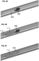
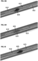
- Figs. 6A-6L are a series of animations illustrating a deployment and treatment procedure using the clot removal device as described in Figs. 1-5 , according to some embodiments.
- a device catheter 602 with a guide wire penetrates the clot and transcends the clot.
- device catheter is withdrawn to reveal guide wire 615, and further, distal filter mesh 610 is expanded or deployed beyond the clot, which acts to substantially prevent the clot or clot particles from flowing downstream.
- Figs. 6A after positioning the clot retrieval device proximal to a target clot 605, a device catheter 602 with a guide wire penetrates the clot and transcends the clot.
- Figs. 6B and 6C device catheter is withdrawn to reveal guide wire 615, and further, distal filter mesh 610 is expanded or deployed beyond the clot, which acts to substantially prevent the clot or clot particles from flowing downstream.
- Figs. 6A after positioning the clot
- clot grabbing, stabilizing or holding element 620 is revealed. Further, grabbing element 620 expands as per a preconfigured design, to help grab or grip target clot 605.
- further withdrawal of catheter 602, or usage of another controller enables expansion of a proximal filter mesh 625, proximal to target clot 605.
- extraction of guide wire 615 or other controller element(s) allows distal mesh 610 to be partially withdrawn, thereby grabbing clot 605 into the receiving proximal mesh 625.
Landscapes
- Health & Medical Sciences (AREA)
- Surgery (AREA)
- Life Sciences & Earth Sciences (AREA)
- Heart & Thoracic Surgery (AREA)
- Nuclear Medicine, Radiotherapy & Molecular Imaging (AREA)
- Vascular Medicine (AREA)
- Engineering & Computer Science (AREA)
- Biomedical Technology (AREA)
- Orthopedic Medicine & Surgery (AREA)
- Medical Informatics (AREA)
- Molecular Biology (AREA)
- Animal Behavior & Ethology (AREA)
- General Health & Medical Sciences (AREA)
- Public Health (AREA)
- Veterinary Medicine (AREA)
- Surgical Instruments (AREA)
Claims (15)
- Eine Vorrichtung zum Entfernen von Gerinnseln, die Folgendes umfasst: einen Führungsdraht (615); ein distales Filter-Mesh (610), das auf dem genannten Führungsdraht (615) angebracht ist und dazu ausgelegt ist, ausgezogen zu werden, um das Zielgerinnsel (605) zu bedecken, wobei das genannte distale Filter-Mesh (610) dazu ausgelegt ist, stromabwärts von dem Zielgerinnsel (605) abgelegt zu werden, um im Wesentlichen eine Stromabwärts-Migration von Gerinnselelementen zu verhindern; und ein proximales Filter-Mesh (625), das auf der proximalen Seite des Zielgerinnsels (605) geöffnet werden kann, das dazu ausgelegt ist, das Durchfließen von Gerinnselelementen abzuschwächen,
dadurch gekennzeichnet, dassdie genannte Vorrichtung zum Entfernen von Gerinnseln einen oder mehrere Steuerdrähte (115, 120) und ein expandierbares Gerinnselhalteelement (620) umfasst, das zum Penetrieren und Expandieren innerhalb des Zielgerinnsels (605) und Stabilisieren und Sichern des Zielgerinnsels (605) in seiner Position in einem zwischen dem proximalen Filter-Mesh (625) und dem distalen Filter-Mesh (610) definierten Gerinnselhaltebereich ausgelegt ist,wobei das distale Filter-Mesh (610) zum steuerbaren Expandieren oder Zurückziehen durch den genannten einen oder die mehreren Steuerdrähte (115, 120) ausgelegt ist, um das Zielgerinnsel (605) dort im Inneren einzufangen und es in den proximalen Filter-Mesh (625) zu ziehen und das genannte distale und proximale Filter-Mesh (610, 625) miteinander zu verbinden und das Zielgerinnsel (605) zu sichern, das innerhalb des Gerinnselhaltebereichs durch das genannte expandierbare Gerinnselhalteelement (620) stabilisiert wird. - Vorrichtung nach Anspruch 1, die ferner einen proximalen Ballon (380) umfasst, der dazu konzipiert ist, das Zielgerinnsel (605) einzukapseln, bevor es durch die Vorrichtung zum Entfernen von Gerinnseln herausgeholt wird.
- Vorrichtung nach Anspruch 1, wobei das expandierbare Gerinnselhalteelement (620) einen Rahmen aus Gedächtnismaterial umfasst, der dazu konzipiert ist, im Innern des Zielgerinnsels (605) zu expandieren, um das Zielgerinnsel in seiner aktuellen Position zu stabilisieren.
- Vorrichtung nach Anspruch 1, wobei das distale Filter-Mesh (610) Lückengrößen mit einer Vielzahl von Größen aufweist, um zu ermöglichen, dass ein Austreten eines Gerinnselanteils im Wesentlichen verhindert wird, und gleichzeitig ein wesentlicher Blutfluss während eines Verfahrens zum Entfernen von Gerinnseln ermöglicht wird.
- Vorrichtung nach Anspruch 1, wobei das distale Filter-Mesh (610) dazu konzipiert ist, geöffnet werden zu können, wenn es sich in einer Position stromabwärts von dem Zielgerinnsel (605) befindet.
- Vorrichtung nach Anspruch 1, das ferner einen Behandlungskatheter (602) umfasst, der dazu konzipiert ist, die Elemente der Vorrichtung zum Entfernen von Gerinnseln innerhalb des Katheters (602) während des Einführens in ein Gefäß zusammengedrückt zu halten, und der eine gesteuerte Expansion und/oder Kontraktion von einem oder mehreren Elementen der Vorrichtung zum Entfernen von Gerinnseln während eines Verfahrens zum Entfernen von Gerinnseln zu ermöglichen.
- Vorrichtung nach Anspruch 1, wobei das distale Filter-Mesh (610) und/oder das proximale Filter-Mesh (625) mit einer Antikoagulansverbindung beschichtet sind oder mit einer Medikations- oder Behandlungsverbindung beschichtet sind.
- Vorrichtung nach Anspruch 1, wobei das expandierbare Gerinnselhalteelement radial expandierbar ist, um dadurch das Zielgerinnsel in dem Gerinnselhaltebereich zu halten und stabilisieren.
- Vorrichtung nach Anspruch 1, wobei das distale Filter-Mesh (610) und/oder proximale Filter-Mesh (625) jeweils einen Rohrabschnitt umfassen, der dazu ausgelegt ist, parallel zu einer Innenwand des Gefäßes ausgezogen zu werden.
- Vorrichtung nach Anspruch 1, wobei das distale Filter-Mesh (610) und/oder das proximale Filter-Mesh (625) jeweils dazu ausgelegt sind, eine Länge, die mehr als das Zweifache des jeweiligen Durchmessers beträgt, wenn das Filter-Mesh geöffnet ist, aufzuweisen.
- Vorrichtung nach Anspruch 1, wobei das distale Mesh-Filter und/oder das proximale Mesh-Filter mit einer Medikations- oder Behandlungsverbindung beschichtet sind.
- Vorrichtung nach Anspruch 1, wobei das distale Mesh-Filter (610) und/oder das proximale Mesh-Filter (625) vorgeformte Nitinoldrähte umfassen.
- Vorrichtung nach Anspruch 1, wobei das distale Mesh-Filter (610) und/oder das proximale Mesh-Filter (625) durch Flechten, Weben, Stricken oder Bohren von Löchern mit Lasern hergestellt sind.
- Vorrichtung nach Anspruch 1, wobei mindestens eines von dem proximalen Mesh-Filter (625) und dem distalen Mesh-Filter (610) Drahtkonfigurationen sind, die mit einer Mesh-Struktur mit einer Dicke von etwa 20-30 Mikrometer konzipiert sind.
- Vorrichtung nach Anspruch 1, wobei eine Dichte der Öffnungen des distalen Mesh-Filters (610) und/oder des proximalen Mesh-Filters (625) in einem mittleren Abschnitt größer und an deren Seiten kleiner ist.
Applications Claiming Priority (2)
| Application Number | Priority Date | Filing Date | Title |
|---|---|---|---|
| US201762449296P | 2017-01-23 | 2017-01-23 | |
| PCT/IB2018/050407 WO2018134801A2 (en) | 2017-01-23 | 2018-01-23 | An apparatus and a method for clot and plaque retracting |
Publications (4)
| Publication Number | Publication Date |
|---|---|
| EP3570778A2 EP3570778A2 (de) | 2019-11-27 |
| EP3570778A4 EP3570778A4 (de) | 2020-10-14 |
| EP3570778C0 EP3570778C0 (de) | 2024-10-30 |
| EP3570778B1 true EP3570778B1 (de) | 2024-10-30 |
Family
ID=62909207
Family Applications (1)
| Application Number | Title | Priority Date | Filing Date |
|---|---|---|---|
| EP18741937.9A Active EP3570778B1 (de) | 2017-01-23 | 2018-01-23 | Vorrichtung zum zurückziehen von gerinnseln und plaques |
Country Status (4)
| Country | Link |
|---|---|
| US (1) | US11202647B2 (de) |
| EP (1) | EP3570778B1 (de) |
| CN (1) | CN110494099B (de) |
| WO (1) | WO2018134801A2 (de) |
Families Citing this family (3)
| Publication number | Priority date | Publication date | Assignee | Title |
|---|---|---|---|---|
| CN111588441A (zh) * | 2020-06-03 | 2020-08-28 | 上海心玮医疗科技有限公司 | 一种立体式取栓支架 |
| US11864787B2 (en) | 2021-07-28 | 2024-01-09 | Sanford Altman | Thrombectomy device and methods of use |
| IL285744B2 (en) | 2021-08-19 | 2023-08-01 | Inretio Ltd | blood clot removal device |
Family Cites Families (17)
| Publication number | Priority date | Publication date | Assignee | Title |
|---|---|---|---|---|
| US20030191492A1 (en) * | 2002-04-05 | 2003-10-09 | Scimed Life Systems, Inc. | Radial coil expandable medical wire |
| US20050085826A1 (en) * | 2003-10-21 | 2005-04-21 | Scimed Life Systems, Inc. | Unfolding balloon catheter for proximal embolus protection |
| US8632562B2 (en) * | 2005-10-03 | 2014-01-21 | Cook Medical Technologies Llc | Embolic protection device |
| WO2009076482A1 (en) * | 2007-12-10 | 2009-06-18 | Incept, Llc | Retrieval apparatus and methods for use |
| US8852206B2 (en) * | 2008-06-12 | 2014-10-07 | The Regents Of The University Of Michigan | Probe insertion device for implanting a probe into tissue |
| WO2010046897A1 (en) | 2008-10-24 | 2010-04-29 | Rapid Medical Ltd. | Embolectomy device containing a distal and proximal effecter |
| US20110152920A1 (en) | 2008-12-02 | 2011-06-23 | Rapid Medical Ltd. | Embolectomy device |
| WO2011119872A1 (en) | 2010-03-24 | 2011-09-29 | Nexgen Medical Systems, Inc. | Thrombus removal system and process |
| US8858497B2 (en) | 2010-09-07 | 2014-10-14 | Angio Dynamics, Inc. | Device and method for removing material from a hollow anatomical structure |
| EP2683309B1 (de) * | 2011-03-09 | 2021-04-21 | Neuravi Limited | Gerinnselentfernungsvorrichtung zum entfernen von okklusiven blutgerinnseln aus einem blutgefäss |
| US20140303667A1 (en) * | 2011-12-02 | 2014-10-09 | Inceptus Medical, Llc | Embolic protection device and methods of use |
| US20150265299A1 (en) * | 2012-10-03 | 2015-09-24 | Christopher J. Cooper | Minimally Invasive Thrombectomy |
| WO2014059005A1 (en) * | 2012-10-09 | 2014-04-17 | Boston Scientific Scimed, Inc. | Special opening aortic embolic protection device for structural heart procedures |
| US9456834B2 (en) * | 2012-10-31 | 2016-10-04 | Covidien Lp | Thrombectomy device with distal protection |
| US9314248B2 (en) * | 2012-11-06 | 2016-04-19 | Covidien Lp | Multi-pivot thrombectomy device |
| US9724112B2 (en) * | 2013-03-15 | 2017-08-08 | Cook Medical Technologies Llc | Shape memory metal emboli trap |
| CA2940491C (en) * | 2014-03-04 | 2022-06-07 | Likemark Medical, Inc. | Intravascular thromboembolectomy device having a plurality of clot engaging elements |
-
2018
- 2018-01-23 CN CN201880008101.XA patent/CN110494099B/zh active Active
- 2018-01-23 US US16/479,990 patent/US11202647B2/en not_active Expired - Fee Related
- 2018-01-23 WO PCT/IB2018/050407 patent/WO2018134801A2/en not_active Ceased
- 2018-01-23 EP EP18741937.9A patent/EP3570778B1/de active Active
Also Published As
| Publication number | Publication date |
|---|---|
| US11202647B2 (en) | 2021-12-21 |
| EP3570778A2 (de) | 2019-11-27 |
| US20190365397A1 (en) | 2019-12-05 |
| WO2018134801A2 (en) | 2018-07-26 |
| CN110494099A (zh) | 2019-11-22 |
| EP3570778A4 (de) | 2020-10-14 |
| EP3570778C0 (de) | 2024-10-30 |
| CN110494099B (zh) | 2022-04-26 |
| WO2018134801A3 (en) | 2018-10-04 |
Similar Documents
| Publication | Publication Date | Title |
|---|---|---|
| US12471941B2 (en) | Clot engagement and removal system | |
| US11633202B1 (en) | Catheter based retrieval device with proximal body having axial freedom of movement | |
| CN109906058B (zh) | 用于从血管移除闭塞凝块的凝块取回装置 | |
| AU2016273879B2 (en) | Devices and systems for thrombus treatment | |
| BR102021001185A2 (pt) | Dispositivo para icad de camada dupla | |
| JP2007503918A (ja) | 動脈塞栓を捕捉及び除去するための血管内スネア | |
| GB2487970A (en) | Obstruction capture and removal device | |
| EP3570778B1 (de) | Vorrichtung zum zurückziehen von gerinnseln und plaques | |
| HK40036984B (en) | Catheter based retrieval device with proximal body having axial freedom of movement | |
| HK40036984A (en) | Catheter based retrieval device with proximal body having axial freedom of movement |
Legal Events
| Date | Code | Title | Description |
|---|---|---|---|
| STAA | Information on the status of an ep patent application or granted ep patent |
Free format text: STATUS: THE INTERNATIONAL PUBLICATION HAS BEEN MADE |
|
| PUAI | Public reference made under article 153(3) epc to a published international application that has entered the european phase |
Free format text: ORIGINAL CODE: 0009012 |
|
| STAA | Information on the status of an ep patent application or granted ep patent |
Free format text: STATUS: REQUEST FOR EXAMINATION WAS MADE |
|
| 17P | Request for examination filed |
Effective date: 20190808 |
|
| AK | Designated contracting states |
Kind code of ref document: A2 Designated state(s): AL AT BE BG CH CY CZ DE DK EE ES FI FR GB GR HR HU IE IS IT LI LT LU LV MC MK MT NL NO PL PT RO RS SE SI SK SM TR |
|
| AX | Request for extension of the european patent |
Extension state: BA ME |
|
| DAV | Request for validation of the european patent (deleted) | ||
| DAX | Request for extension of the european patent (deleted) | ||
| A4 | Supplementary search report drawn up and despatched |
Effective date: 20200914 |
|
| RIC1 | Information provided on ipc code assigned before grant |
Ipc: A61M 25/00 20060101ALI20200908BHEP Ipc: A61F 2/01 20060101AFI20200908BHEP Ipc: A61B 17/3207 20060101ALI20200908BHEP Ipc: A61B 17/221 20060101ALI20200908BHEP Ipc: A61B 17/22 20060101ALI20200908BHEP |
|
| STAA | Information on the status of an ep patent application or granted ep patent |
Free format text: STATUS: EXAMINATION IS IN PROGRESS |
|
| 17Q | First examination report despatched |
Effective date: 20220112 |
|
| GRAP | Despatch of communication of intention to grant a patent |
Free format text: ORIGINAL CODE: EPIDOSNIGR1 |
|
| STAA | Information on the status of an ep patent application or granted ep patent |
Free format text: STATUS: GRANT OF PATENT IS INTENDED |
|
| INTG | Intention to grant announced |
Effective date: 20240524 |
|
| GRAS | Grant fee paid |
Free format text: ORIGINAL CODE: EPIDOSNIGR3 |
|
| GRAA | (expected) grant |
Free format text: ORIGINAL CODE: 0009210 |
|
| STAA | Information on the status of an ep patent application or granted ep patent |
Free format text: STATUS: THE PATENT HAS BEEN GRANTED |
|
| AK | Designated contracting states |
Kind code of ref document: B1 Designated state(s): AL AT BE BG CH CY CZ DE DK EE ES FI FR GB GR HR HU IE IS IT LI LT LU LV MC MK MT NL NO PL PT RO RS SE SI SK SM TR |
|
| REG | Reference to a national code |
Ref country code: GB Ref legal event code: FG4D |
|
| REG | Reference to a national code |
Ref country code: CH Ref legal event code: EP |
|
| REG | Reference to a national code |
Ref country code: DE Ref legal event code: R096 Ref document number: 602018075975 Country of ref document: DE |
|
| REG | Reference to a national code |
Ref country code: IE Ref legal event code: FG4D |
|
| U01 | Request for unitary effect filed |
Effective date: 20241125 |
|
| U07 | Unitary effect registered |
Designated state(s): AT BE BG DE DK EE FI FR IT LT LU LV MT NL PT RO SE SI Effective date: 20241129 |
|
| U20 | Renewal fee for the european patent with unitary effect paid |
Year of fee payment: 8 Effective date: 20250103 |
|
| PG25 | Lapsed in a contracting state [announced via postgrant information from national office to epo] |
Ref country code: IS Free format text: LAPSE BECAUSE OF FAILURE TO SUBMIT A TRANSLATION OF THE DESCRIPTION OR TO PAY THE FEE WITHIN THE PRESCRIBED TIME-LIMIT Effective date: 20250228 Ref country code: HR Free format text: LAPSE BECAUSE OF FAILURE TO SUBMIT A TRANSLATION OF THE DESCRIPTION OR TO PAY THE FEE WITHIN THE PRESCRIBED TIME-LIMIT Effective date: 20241030 |
|
| PG25 | Lapsed in a contracting state [announced via postgrant information from national office to epo] |
Ref country code: ES Free format text: LAPSE BECAUSE OF FAILURE TO SUBMIT A TRANSLATION OF THE DESCRIPTION OR TO PAY THE FEE WITHIN THE PRESCRIBED TIME-LIMIT Effective date: 20241030 |
|
| PG25 | Lapsed in a contracting state [announced via postgrant information from national office to epo] |
Ref country code: NO Free format text: LAPSE BECAUSE OF FAILURE TO SUBMIT A TRANSLATION OF THE DESCRIPTION OR TO PAY THE FEE WITHIN THE PRESCRIBED TIME-LIMIT Effective date: 20250130 |
|
| PG25 | Lapsed in a contracting state [announced via postgrant information from national office to epo] |
Ref country code: GR Free format text: LAPSE BECAUSE OF FAILURE TO SUBMIT A TRANSLATION OF THE DESCRIPTION OR TO PAY THE FEE WITHIN THE PRESCRIBED TIME-LIMIT Effective date: 20250131 |
|
| PG25 | Lapsed in a contracting state [announced via postgrant information from national office to epo] |
Ref country code: PL Free format text: LAPSE BECAUSE OF FAILURE TO SUBMIT A TRANSLATION OF THE DESCRIPTION OR TO PAY THE FEE WITHIN THE PRESCRIBED TIME-LIMIT Effective date: 20241030 |
|
| PG25 | Lapsed in a contracting state [announced via postgrant information from national office to epo] |
Ref country code: RS Free format text: LAPSE BECAUSE OF FAILURE TO SUBMIT A TRANSLATION OF THE DESCRIPTION OR TO PAY THE FEE WITHIN THE PRESCRIBED TIME-LIMIT Effective date: 20250130 |
|
| PG25 | Lapsed in a contracting state [announced via postgrant information from national office to epo] |
Ref country code: SM Free format text: LAPSE BECAUSE OF FAILURE TO SUBMIT A TRANSLATION OF THE DESCRIPTION OR TO PAY THE FEE WITHIN THE PRESCRIBED TIME-LIMIT Effective date: 20241030 |
|
| PG25 | Lapsed in a contracting state [announced via postgrant information from national office to epo] |
Ref country code: SK Free format text: LAPSE BECAUSE OF FAILURE TO SUBMIT A TRANSLATION OF THE DESCRIPTION OR TO PAY THE FEE WITHIN THE PRESCRIBED TIME-LIMIT Effective date: 20241030 |
|
| PG25 | Lapsed in a contracting state [announced via postgrant information from national office to epo] |
Ref country code: CZ Free format text: LAPSE BECAUSE OF FAILURE TO SUBMIT A TRANSLATION OF THE DESCRIPTION OR TO PAY THE FEE WITHIN THE PRESCRIBED TIME-LIMIT Effective date: 20241030 |
|
| REG | Reference to a national code |
Ref country code: CH Ref legal event code: PL |
|
| PLBE | No opposition filed within time limit |
Free format text: ORIGINAL CODE: 0009261 |
|
| STAA | Information on the status of an ep patent application or granted ep patent |
Free format text: STATUS: NO OPPOSITION FILED WITHIN TIME LIMIT |
|
| PG25 | Lapsed in a contracting state [announced via postgrant information from national office to epo] |
Ref country code: MC Free format text: LAPSE BECAUSE OF FAILURE TO SUBMIT A TRANSLATION OF THE DESCRIPTION OR TO PAY THE FEE WITHIN THE PRESCRIBED TIME-LIMIT Effective date: 20241030 |
|
| GBPC | Gb: european patent ceased through non-payment of renewal fee |
Effective date: 20250130 |
|
| 26N | No opposition filed |
Effective date: 20250731 |
|
| PG25 | Lapsed in a contracting state [announced via postgrant information from national office to epo] |
Ref country code: GB Free format text: LAPSE BECAUSE OF NON-PAYMENT OF DUE FEES Effective date: 20250130 |
|
| PG25 | Lapsed in a contracting state [announced via postgrant information from national office to epo] |
Ref country code: CH Free format text: LAPSE BECAUSE OF NON-PAYMENT OF DUE FEES Effective date: 20250131 |
|
| PG25 | Lapsed in a contracting state [announced via postgrant information from national office to epo] |
Ref country code: IE Free format text: LAPSE BECAUSE OF NON-PAYMENT OF DUE FEES Effective date: 20250123 |