EP3570310A1 - Vorrichtung zum erzeugen beschleunigter elektronen - Google Patents
Vorrichtung zum erzeugen beschleunigter elektronen Download PDFInfo
- Publication number
- EP3570310A1 EP3570310A1 EP19174559.5A EP19174559A EP3570310A1 EP 3570310 A1 EP3570310 A1 EP 3570310A1 EP 19174559 A EP19174559 A EP 19174559A EP 3570310 A1 EP3570310 A1 EP 3570310A1
- Authority
- EP
- European Patent Office
- Prior art keywords
- cylindrical
- cathode
- shaped
- exit window
- electron exit
- Prior art date
- Legal status (The legal status is an assumption and is not a legal conclusion. Google has not performed a legal analysis and makes no representation as to the accuracy of the status listed.)
- Granted
Links
Images
Classifications
-
- H—ELECTRICITY
- H01—ELECTRIC ELEMENTS
- H01J—ELECTRIC DISCHARGE TUBES OR DISCHARGE LAMPS
- H01J33/00—Discharge tubes with provision for emergence of electrons or ions from the vessel; Lenard tubes
- H01J33/02—Details
- H01J33/04—Windows
-
- G—PHYSICS
- G21—NUCLEAR PHYSICS; NUCLEAR ENGINEERING
- G21K—HANDLING OF PARTICLES OR IONISING RADIATION NOT OTHERWISE PROVIDED FOR; IRRADIATION DEVICES; GAMMA RAY OR X-RAY MICROSCOPES
- G21K5/00—Irradiation devices
- G21K5/02—Irradiation devices having no beam-forming means
Definitions
- the invention relates to a device for generating accelerated electrons.
- inner walls of hollow bodies as well as bulk material and fluids with accelerated electrons can be charged with a device according to the invention.
- Electron beam technology has been used for several decades on an industrial scale for the chemical modification of materials as well as for the disinfection and sterilization of surfaces.
- the treatment of products can be economically advantageous at atmospheric pressure, for which the electrons first released in a vacuum, then accelerated and finally by a beam exit window, usually a thin metal foil, must be coupled into the treatment zone.
- a beam exit window usually a thin metal foil
- Electron beam sources based on thermionic emitters are also mechanically complicated, difficult to scale and require expensive high voltage power supplies and high vacuum systems. In case of damage to the jet exit window with it As a result of the resulting collapse of the vacuum irreversible damage to the cathode system and thus a high repair effort.
- DE 199 42 142 A1 discloses a device in which bulk material is passed in multiple free fall on an electron beam device and charged with accelerated electrons. Due to the multiple pass, combined with an intermediate mixing of the bulk material, the probability in this embodiment is very high that the particles of the bulk material are charged on all sides with accelerated electrons. The multiple pass, however, requires a lot of time in carrying out the treatment process. The disadvantage here is also that the device is unsuitable for the treatment of larger moldings.
- DE 10 2006 012 666 A1 which comprises three axial radiators with associated deflection control and three likewise associated electron exit windows.
- the three electron exit windows are arranged in such a way that they completely surround a triangular free space. If a substrate is guided through this free space, it can be charged in its entirety with accelerated electrons in a treatment passage in its cross section. However, if the substrate does not have the same triangular cross-section as the space enclosed by the three electron exit windows, the dose distribution of the accelerated electron impingement on the surface of the substrate will be inhomogeneous. The expenditure on equipment in this embodiment is also very high, whereby this solution is also very expensive.
- WO 2007/107331 A1 a device is known in which only two area jet generators are needed, between which a molded part for the purpose of sterilizing its surface moves through and can be acted upon while accelerated electrons.
- This device also has a plurality of gold reflectors, which are used to reflect marginal rays emitted by the area beam generators onto surface areas of the molded part which are not in the direct area of action of the area beam generators. Since the reflectors known from this document are made of pure gold, such devices are also very expensive and thus affect their cost-effectiveness. Since reflected electrons have lower energy than non-reflected electrons, only inhomogeneous energy input into a substrate is possible with this device.
- FIG DE 10 2013 111 650 B3 discloses in which all the essential components, such as cathode, anode and electron exit window, are annular, so that by means of such an apparatus, an annular electron beam can be formed, in which the accelerated electrons move towards the ring inside.
- an annular electron beam can be formed, in which the accelerated electrons move towards the ring inside.
- US 2008/0267354 A1 also describes annular devices with which a high dose of X-rays and, incidentally, electron beams can be generated. Due to the generation of a high dose of X-rays, such devices are not suitable for irradiating products entering the food chain of humans or livestock.
- the invention is therefore based on the technical problem of providing a device for generating accelerated electrons, by means of which the disadvantages of the prior art can be overcome.
- a device is to be created with a compact design, with which, for example, hollow body from the inside but also bulk material with accelerated electrons can be applied.
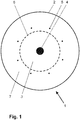
- FIG. 1 a cross section of a device 1 according to the invention is shown schematically.
- Device 1 initially comprises an electron exit window 2 in the form of a hollow cylinder.
- the cylindrical electron exit window 2 is part of a housing, which has the shape of the lateral surfaces of a cylinder and which is therefore likewise cylindrical in shape as the electron exit window 2.
- the cylindrical housing encloses an evacuable space. 3
- the cylindrical electron emission window of a device according to the invention also comprises a mechanical support grid to which a metal foil is attached.
- the electron exit window 2 comprises an in Fig. 1 not shown mechanical support grid made of copper, to which a titanium foil is attached.
- a device which has the shape of a rod or a hollow cylinder and which is thus rod-shaped or cylindrical.
- a rod-shaped electrode In the embodiment of Fig. 1 extends along the cylinder axis of the cylindrical electron exit window 2, a rod-shaped electrode 4.
- wire-shaped electrodes 5 On a circular path around the cylinder axis of the cylindrical electron exit window 2 around, wire-shaped electrodes 5 are arranged at the same distance from each other.
- the wire-shaped electrodes 5 extend completely or partially along the cylinder length of the cylindrical electron exit window through the evacuable space 3 and are connected as an anode.
- the device 1 has a total of eight wire-shaped electrodes 5.
- the number of wire-shaped electrodes of a device according to the invention is not set to eight, but in other embodiments may alternatively be less than or greater than eight.
- the anode-connected wire-shaped electrodes of a device according to the invention preferably have a slightly positive voltage potential in the range of +0.25 kV to 5 kV with respect to the electrical ground of the device 1, whereas the cylindrical housing of a device according to the invention, including the cylindrical electron exit window and the support grid , preferably having electronic ground potential.
- a glow discharge plasma is formed in the evacuable space 3.
- an electric voltage of 1 kV is used to ignite the glow discharge between the wire-shaped electrodes 5 and the first cathode acting housing of the device 1, which drops to 0.3 kV after the ignition of the glow discharge to maintain the glow discharge.
- an electrical voltage in a range of -60 kV to -300 kV can be applied to the central, rod-shaped or cylindrical electrode 4 of a device according to the invention.
- an electrical voltage in the range of -80 kV to -200 kV is applied to the electrode 4.
- the electrode 4 thus acts as the second cathode of a device according to the invention.
- a device further comprises a first grid-shaped electrode 6 in the form of a hollow cylinder, which encloses the at least one second cathode 4, wherein the first grid-shaped and cylindrical electrode 6 is spaced to a smaller extent from the second cathode 4 than the wire-shaped electrodes 5.
- Die The first grid-shaped and cylindrical electrode 6 likewise has the electrical ground potential of the device 1, shields the second cathode 4 from the plasma and thus limits the space for spreading the glow discharge plasma to the volume between the first grid-shaped and cylindrical electrode 6 and the electron exit window 2 This volume in which the glow discharge plasma propagates is also referred to below as the plasma space 7.
- ions from the glow discharge plasma are accelerated in the direction of the cathode 4, which dissolve secondary electrons from the second cathode 4 when they impinge on the surface of the second cathode 4.
- the secondary electrons are in turn accelerated along the field lines of the electric field perpendicularly from the surface of the second cathode 4 in the direction of the first grid-shaped and cylindrical wire-shaped electrodes 5 and finally to the electron exit window 2.
- the surface perpendiculars of the surface region of the cathode from which electrons are emitted are aligned with the cylindrical electron exit window. Electrons which penetrate the electron exit window of a device according to the invention are thus emitted to the external environment of a device according to the invention.
- electrons can be radiated completely outward starting from the centrally arranged second emitter acting as emitter.
- the cylinder axis of a cylindrical device according to the invention for example, be aligned vertically and be passed around the cylinder cross-section around an annular curtain of bulk material in free fall.
- the disadvantage here is that the bulk material can not be fully loaded with accelerated electrons in one pass.
- this deficit can be compensated for by a multiple pass and represents an economic procedure for applying bulk material with accelerated electrons, especially in the case of small quantities of bulk material.
- a cylindrical electron reflector is arranged around a cylindrical device according to the invention, which delimits an annular clearance between the device according to the invention and the cylindrical electron reflector.
- an annular curtain of bulk material at the electron exit window of the device according to the invention can be passed in free fall, wherein the bulk material curtain can be at least partially also applied from the back with accelerated electrons with the electrons reflected at the electron reflector.
- the glow discharge plasma within the device 1 is adjacent to the electron exit window 2, which is accompanied by ion bombardment of the electron exit window 2.
- the resulting sputtering effects can cause damage to the electron exit window 2 over time and the This makes device 1 dysfunctional. Keeping the plasma ions away from the electron exit window is therefore advantageous.
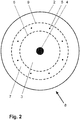
- Fig. 2 is a cross-section of an embodiment of a device 8 according to the invention shown schematically.
- Device 8 comprises first of all all components of the device 1 from Fig. 1 with the same functionality.
- device 8 has a second grid-shaped and cylindrical electrode 9, which encloses the at least one second cathode 4, wherein the second grid-shaped and cylindrical electrode 9 is spaced from the second cathode 4 to a greater extent than the wire-shaped electrodes 5.
- the second grid-shaped and cylindrical electrode 9 preferably has an electrical voltage in the range of the electrical ground potential to +500 volts.
- the plasma region 7 of the device 8 is limited to a volume between the first lattice-shaped and cylindrical electrode 6 and the second lattice-shaped and cylindrical electrode 9, through which the wire-shaped electrodes 5 extend partially or completely.
- the electron exit window 2 of the device 8 is thus shielded from the glow discharge plasma, which prolongs the life of the electron exit window 2.
- the electrical voltage at the wire-shaped electrodes 5 is pulsed.
- the glow discharge plasma of a device according to the invention can be maintained at lower pressures in the evacuable space.
- the at least one electrode 4 acting as the second cathode can also be traversed by at least one channel through which a coolant flows or flows.
- the rod-shaped second cathode 4 of the Fig. 1 and 2 therefore has an in Fig. 1 and 2 not shown central through hole through which a coolant flows.
- a device according to the invention can be produced inexpensively and compactly due to its relatively simple and uncomplicated construction. Due to the compact construction with a relatively small volume of vacuum evacuated space of a device according to the invention is evacuated in a further embodiment only in the manufacturing process, a working gas in the evacuated space introduced and the evacuated space then vacuum sealed.
- a device according to the invention may also have first means for evacuating the evacuable space and second means for supplying a working gas into the evacuable space.
- first means for evacuating the evacuable space and second means for supplying a working gas into the evacuable space.
- the evacuation of the evacuable space and the supply of the working gas can take place continuously or with a time interruption.
- the accesses for the first and second means to be evacuated space 3 of a device according to the invention are preferably mounted on the cylinder bottom and / or on the cylinder ceiling of a cylindrical device according to the invention.
- the preceding descriptions of devices according to the invention refers to a preferred embodiment in which the cross sections of all designated as cylindrical, ring and rod-shaped components are circular.
- the cross sections of the components designated as cylindrical, ring-shaped or rod-shaped in the case of a device according to the invention can also have any geometric shape deviating from circular.
Landscapes
- Physics & Mathematics (AREA)
- Engineering & Computer Science (AREA)
- General Engineering & Computer Science (AREA)
- High Energy & Nuclear Physics (AREA)
- Electron Sources, Ion Sources (AREA)
- Physical Or Chemical Processes And Apparatus (AREA)
- Apparatus For Disinfection Or Sterilisation (AREA)
Abstract
Description
- Die Erfindung betrifft eine Vorrichtung zum Erzeugen beschleunigter Elektronen. Insbesondere können mit einer erfindungsgemäßen Vorrichtung Innenwandungen von Hohlkörpern sowie Schüttgut und Fluide mit beschleunigten Elektronen beaufschlagt werden.
- Elektronenstrahltechnologie wird seit etlichen Jahrzehnten im Industriemaßstab zur chemischen Materialmodifikation sowie zur Desinfektion bzw. Sterilisierung von Oberflächen eingesetzt. Die Behandlung von Produkten kann wirtschaftlich vorteilhaft bei atmosphärischem Druck erfolgen, wozu die Elektronen zunächst im Vakuum freigesetzt, anschließend beschleunigt und schließlich durch ein Strahlaustrittsfenster, zumeist eine dünne Metallfolie, in die Behandlungszone ausgekoppelt werden müssen. Zum Durchdringen großtechnisch einsetzbarer, genügend robuster Elektronenaustrittsfenster sowie auch zum Sichern einer ausreichenden Behandlungstiefe im Produkt sind typischerweise Beschleunigungsspannungen >80 kV erforderlich.
- Verschiedene Verfahren und Strahlquellen sind für eine Randschichtbehandlung flacher Produkte, wie Platten und Bänder, wohletabliert, während das allseitige Behandeln von Formkörpern, Schüttgütern und Fluiden nach wie vor Probleme bereitet. So ist ein allseitiges gleichmäßiges Beaufschlagen gekrümmter Oberflächen mit Elektronen geometrisch problematisch aufgrund von Abschattungseffekten, variabler Absorption von Elektronenenergie auf der Gasstrecke sowie Dosis-Inhomogenitäten wegen unterschiedlicher Projektionsverhältnisse.
- Mit den bereits existierenden Quellensystemen, wie beispielsweise Axialstrahlern mit einer schnellen Ablenkeinheit oder Bandstrahlern mit einer langgestreckten Kathode, von denen beide Ausführungsformen mit einer geheizten thermionischen Kathode betrieben werden, ist eine allseitige Produktbehandlung nur umständlich, unter Nutzung zusätzlicher Einrichtungen oder mit einem hohen apparativen und/oder technologischen Aufwand möglich. Elektronenstrahlquellen auf Basis thermionischer Emitter sind außerdem mechanisch kompliziert, schwierig zu skalieren und erfordern aufwändige Hochspannungsversorgungen und Hochvakuumsysteme. Bei einer Beschädigung des Strahlaustrittsfensters mit daraus resultierendem Zusammenbruch des Vakuums kommt es zur irreversiblen Schädigung des Kathodensystems und somit zu einem hohen Reparaturaufwand.
- In
DE 199 42 142 A1 ist eine Vorrichtung offenbart, bei der Schüttgut im mehrfachen freien Fall an einer Elektronenstrahleinrichtung vorbeigeführt und mit beschleunigten Elektronen beaufschlagt wird. Aufgrund des Mehrfachdurchlaufs, verbunden mit einer zwischenzeitlichen Durchmischung des Schüttguts, ist die Wahrscheinlichkeit bei dieser Ausführungsform sehr hoch, dass die Partikel des Schüttgutes allseitig mit beschleunigten Elektronen beaufschlagt werden. Der Mehrfachdurchlauf erfordert allerdings einen hohen Zeitaufwand bei der Durchführung des Behandlungsprozesses. Nachteilig ist hierbei außerdem, dass die Vorrichtung für die Behandlung größerer Formteile ungeeignet ist. - Eine andere Lösung ist in
DE 10 2006 012 666 A1 angegeben, welche drei Axialstrahler mit zugehöriger Ablenksteuerung und drei ebenfalls zugehörige Elektronenaustrittsfenster umfasst. Die drei Elektronenaustrittsfenster sind derart angeordnet, dass sie einen dreieckigen Freiraum vollumfänglich umschließen. Wird ein Substrat durch diesen Freiraum geführt, kann dieses in einem Behandlungsdurchgang in seinem Querschnitt vollumfänglich mit beschleunigten Elektronen beaufschlagt werden. Hat das Substrat jedoch nicht den gleichen dreieckigen Querschnitt wie der von den drei Elektronenaustrittsfenstern umschlossene Freiraum, wird die Dosisverteilung der Beaufschlagung mit beschleunigten Elektronen auf der Oberfläche des Substrates inhomogen ausfallen. Der apparative Aufwand bei dieser Ausführungsform ist außerdem sehr hoch, wodurch diese Lösung auch sehr preisintensiv ist. - Aus
WO 2007/107331 A1 ist eine Vorrichtung bekannt, bei der lediglich zwei Flächenstrahlerzeuger benötigt werden, zwischen denen ein Formteil zum Zwecke des Sterilisierens seiner Oberfläche hindurch bewegt und währenddessen mit beschleunigten Elektronen beaufschlagt werden kann. Diese Vorrichtung weist außerdem mehrere Reflektoren aus Gold auf, mit denen von den Flächenstrahlerzeugern abgegebene Randstrahlen auf Oberflächenbereiche des Formteils reflektiert werden, die nicht im unmittelbaren Einwirkbereich der Flächenstrahlerzeuger liegen. Da die aus dieser Schrift bekannten Reflektoren aus reinem Gold bestehen, sind derartige Vorrichtungen ebenfalls sehr preisintensiv und beeinträchtigen somit deren Wirtschaftlichkeit. Da reflektierte Elektronen eine geringere Energie aufweisen als nicht reflektierte Elektronen, ist auch mit dieser Vorrichtung nur ein inhomogener Energieeintrag in ein Substrat möglich. - Eine ringförmige Vorrichtung zum Erzeugen beschleunigter Elektronen ist in
DE 10 2013 111 650 B3 offenbart, bei welcher alle wesentlichen Komponenten, wie beispielsweise Kathode, Anode und Elektronenaustrittsfenster, ringförmig ausgebildet sind, so dass mittels einer solchen Vorrichtung ein ringförmiger Elektronenstrahl ausgebildet werden kann, bei welchem sich die beschleunigten Elektronen zum Ringinneren hin bewegen. Mittels einer solchen Vorrichtung können beispielsweise strangförmige Substrate, die durch die Ringöffnung der Vorrichtung hindurchbewegt werden, bezüglich des Substratquerschnittes vollumfänglich mit beschleunigten Elektronen beaufschlagt werden. Nachteilig hierbei ist, dass derartige Vorrichtungen in ihrer Bauweise großvolumig sind und eine Elektronenbehandlung von Substraten lediglich im relativ geringen Volumen des Ringinneren vollzogen werden kann. -
US 2008/0267354 A1 beschreibt ebenfalls ringförmige Vorrichtungen, mit denen eine hohe Dosis an Röntgenstrahlen und nebenher auch Elektronenstrahlen erzeugt werden können. Aufgrund des Erzeugens einer hohen Dosis an Röntgenstrahlen sind derartige Vorrichtungen nicht geeignet zum Bestrahlen von Produkten, welche in die Nahrungskette von Menschen oder Nutztieren eingehen. - Der Erfindung liegt daher das technische Problem zugrunde, eine Vorrichtung zum Erzeugen beschleunigter Elektronen zu schaffen, mittels der die Nachteile des Standes der Technik überwunden werden können. Insbesondere soll eine Vorrichtung mit kompakter Bauform geschaffen werden, mit welcher beispielsweise Hohlkörper von innen aber auch Schüttgut mit beschleunigten Elektronen beaufschlagt werden können.
- Die Lösung des technischen Problems ergibt sich durch Gegenstände mit den Merkmalen des Patentanspruchs 1. Weitere vorteilhafte Ausgestaltungen der Erfindung ergeben sich aus den abhängigen Patentansprüchen.
- Die Erfindung wird nachfolgend anhand von Ausführungsbeispielen näher beschrieben. Die Figuren zeigen:
- Fig. 1
- eine schematische Querschnittsdarstellung einer erfindungsgemäßen Vorrichtung
- Fig. 2
- eine schematische Querschnittsdarstellung einer Ausführungsform einer erfindungsgemäßen Vorrichtung
- In
Fig. 1 ist ein Querschnitt einer erfindungsgemäßen Vorrichtung 1 schematisch dargestellt. Vorrichtung 1 umfasst zunächst ein Elektronenaustrittsfenster 2 in Form eines Hohlzylinders. Das zylinderförmige Elektronenaustrittsfenster 2 ist Bestandteil eines Gehäuses, welches die Form der Mantelflächen eines Zylinders aufweist und welches somit ebenfalls zylinderförmig ausgebildet ist wie das Elektronenaustrittsfenster 2. Das zylinderförmige Gehäuse umschließt einen evakuierbaren Raum 3. - Wie es aus dem Stand der Technik bekannt ist, umfasst auch das zylinderförmige Elektronenaustrittsfenster einer erfindungsgemäßen Vorrichtung ein mechanisches Stützgitter, an welchem eine Metallfolie befestigt ist. Im Ausführungsbeispiel von
Fig. 1 umfasst das Elektronenaustrittsfenster 2 ein inFig. 1 nicht dargestelltes mechanisches Stützgitter aus Kupfer, an welchem eine Titanfolie befestigt ist. - Entlang der Zylinderachse des zylinderförmigen Elektronenaustrittsfensters erstreckt sich als zentraler Bestandteil einer erfindungsgemäßen Vorrichtung mindestens eine Elektrode, welche die Form eines Stabes oder eines Hohlzylinders aufweist und welche somit stabförmig oder zylinderförmig ausgebildet ist. Im Ausführungsbeispiel von
Fig. 1 erstreckt sich entlang der Zylinderachse des zylinderförmigen Elektronenaustrittsfensters 2 eine stabförmige Elektrode 4. Auf einer Kreisbahn um die Zylinderachse des zylinderförmigen Elektronenaustrittsfensters 2 herum, sind drahtförmige Elektroden 5 mit gleichem Abstand zueinander angeordnet. Die drahtförmigen Elektroden 5 erstecken sich entlang der Zylinderlänge des zylinderförmigen Elektronenaustrittsfensters vollständig oder teilweise durch den evakuierbaren Raum 3 und sind als Anode geschaltet. Im Ausführungsbeispiel weist die Vorrichtung 1 insgesamt acht drahtförmige Elektroden 5 auf. - Die Anzahl der drahtförmigen Elektroden einer erfindungsgemäßen Vorrichtung ist aber nicht auf acht festgelegt, sondern kann in anderen Ausführungsbeispielen alternativ auch kleiner oder größer als acht sein.
- Die als Anode geschalteten drahtförmigen Elektroden einer erfindungsgemäßen Vorrichtung weisen bevorzugt ein leicht positives Spannungspotenzial im Bereich von +0,25 kV bis 5 kV bezüglich der elektrischen Masse der Vorrichtung 1 auf, wohingegen das zylinderförmige Gehäuse einer erfindungsgemäßen Vorrichtung, einschließlich des zylinderförmigen Elektronenaustrittsfensters und des Stützgitters, bevorzugt das elektronische Massepotenzial aufweisen.
- Aufgrund der Spannungsdifferenz zwischen den als Anode geschalteten drahtförmigen Elektroden 5 und dem als erste Kathode fungierendem Gehäuse der Vorrichtung 1 wird ein Glimmentladungsplasma im evakuierbaren Raum 3 ausgebildet. Im Ausführungsbeispiel wird zum Zünden der Glimmentladung zwischen den drahtförmigen Elektroden 5 und dem als erste Kathode fungierendem Gehäuse der Vorrichtung 1 eine elektrische Spannung von 1 kV verwendet, welche nach dem Zünden der Glimmentladung zum Aufrechterhalten der Glimmentladung auf 0,3 kV absinkt.
- An die zentrale, stabförmige oder zylinderförmige Elektrode 4 einer erfindungsgemäßen Vorrichtung kann beispielsweise eine elektrische Spannung in einem Bereich von -60 kV bis -300 kV angelegt sein. Bevorzugt ist an der Elektrode 4 eine elektrische Spannung im Bereich von -80 kV bis -200 kV angelegt. Die Elektrode 4 fungiert somit als zweite Kathode einer erfindungsgemäßen Vorrichtung.
- Eine erfindungsgemäße Vorrichtung umfasst ferner eine erste gitterförmige Elektrode 6 in Form eines Hohlzylinders, welche die mindestens eine zweite Kathode 4 umschließt, wobei die erste gitterförmige und zylinderförmige Elektrode 6 mit einem kleineren Maß von der zweiten Kathode 4 beabstandet ist als die drahtförmigen Elektroden 5. Die erste gitterförmige und zylinderförmige Elektrode 6 weist ebenfalls das elektrische Massepotenzial der Vorrichtung 1 auf, schirmt die zweite Kathode 4 gegenüber dem Plasma ab und begrenzt somit den Raum für das Ausbreiten des Glimmentladungsplasmas auf das Volumen zwischen der ersten gitterförmigen und zylinderförmigen Elektrode 6 und dem Elektronenaustrittsfenster 2. Dieses Volumen, in welchem sich das Glimmentladungsplasma ausbreitet, wird nachfolgend auch als Plasmaraum 7 bezeichnet.
- Aufgrund der Spannungsdifferenz zwischen der zweiten Kathode 4 und den als Anode fungierenden drahtförmigen Elektroden 5 werden Ionen aus dem Glimmentladungsplasma in Richtung Kathode 4 beschleunigt, welche beim Auftreffen auf der Oberfläche der zweiten Kathode 4 Sekundärelektronen aus der zweiten Kathode 4 herauslösen. Die Sekundärelektronen werden wiederum entlang der Feldlinien des elektrischen Feldes senkrecht von der Oberfläche der zweiten Kathode 4 in Richtung der ersten gitterförmigen und zylinderförmigen drahtförmigen Elektroden 5 und schließlich zum Elektronenaustrittsfenster 2 beschleunigt.
- Wegen der zentralen Anordnung der zylinderförmigen oder stabförmigen zweiten Kathode im zylinderförmigen Gehäuse einer erfindungsgemäßen Vorrichtung, welches das zylinderförmige Elektronenaustrittsfenster umfasst, sind die Oberflächensenkrechten des Oberflächenbereichs der Kathode, aus dem Elektronen emittierbar sind, zum zylinderförmigen Elektronenaustrittsfenster hin ausgerichtet. Elektronen, welche das Elektronenaustrittsfenster einer erfindungsgemäßen Vorrichtung durchdringen, werden somit an die äußere Umgebung einer erfindungsgemäßen Vorrichtung abgestrahlt. Bezüglich des Querschnitts einer erfindungsgemäßen Vorrichtung können daher Elektronen, ausgehend von der zentral angeordneten und als Emitter fungierenden zweiten Kathode, vollumfänglich nach außen abgestrahlt werden. Damit ist eine kompakte und relativ preiswerte Bauform geschaffen, mit welcher beispielsweise Schüttgut, Fluide oder Hohlrauminnenwandungen von Substraten mit beschleunigten Elektronen beaufschlagt werden können. Hierzu kann die Zylinderachse einer zylinderförmigen erfindungsgemäßen Vorrichtung beispielsweise senkrecht ausgerichtet sein und um den Zylinderquerschnitt herum ein ringförmiger Vorhang aus Schüttgut im freien Fall vorbeigeführt werden. Nachteilig wirkt sich hierbei aus, dass das Schüttgut nicht in einem Durchlauf vollumfänglich mit beschleunigten Elektronen beaufschlagt werden kann. Dieses Defizit ist aber mit einem Mehrfachdurchlauf ausgleichbar und stellt insbesondere bei geringen Schüttgutmengen eine wirtschaftliche Vorgehensweise zum Beaufschlagen von Schüttgut mit beschleunigten Elektronen dar.
- Bei einer Ausführungsform ist um eine zylinderförmige erfindungsgemäße Vorrichtung herum noch ein zylinderförmiger Elektronenreflektor angeordnet, welcher einen ringförmigen Freiraum zwischen erfindungsgemäßer Vorrichtung und zylinderförmigen Elektronenreflektor begrenzt. Durch diesen ringförmigen Freiraum kann beispielsweise ein ringförmiger Vorhang von Schüttgut am Elektronenaustrittsfenster der erfindungsgemäßen Vorrichtung im freien Fall vorbeigeführt werden, wobei mit den am Elektronenreflektor reflektierten Elektronen der Schüttgutvorhang zumindest teilweise auch noch von der Rückseite her mit beschleunigten Elektronen beaufschlagt werden kann.
- Wie zuvor beschrieben, grenzt das Glimmentladungsplasma innerhalb der Vorrichtung 1 an das Elektronenaustrittsfenster 2, was mit einen Ionenbombardement des Elektronenaustrittsfensters 2 einhergeht. Die dadurch auftretenden Sputtereffekte können mit der Zeit eine Beschädigung des Elektronenaustrittsfensters 2 hervorrufen und die Vorrichtung 1 dadurch funktionsuntüchtig machen. Die Plasmaionen vom Elektronenaustrittsfenster fernzuhalten, ist daher vorteilhaft.
- In
Fig. 2 ist ein Querschnitt einer Ausführungsform einer erfindungsgemäßen Vorrichtung 8 schematisch dargestellt. Vorrichtung 8 umfasst zunächst einmal alle Bauelemente der Vorrichtung 1 ausFig. 1 mit gleicher Funktionsweise. Zusätzlich weist Vorrichtung 8 eine zweite gitterförmige und zylinderförmige Elektrode 9 auf, welche die mindestens eine zweite Kathode 4 umschließt, wobei die zweite gitterförmige und zylinderförmige Elektrode 9 mit einem größeren Maß von der zweiten Kathode 4 beabstandet ist als die drahtförmigen Elektroden 5. Die zweite gitterförmige und zylinderförmige Elektrode 9 weist vorzugsweise eine elektrische Spannung im Bereich vom elektrischen Massepotenzial bis +500 V auf. Dadurch wird der Plasmabereich 7 der Vorrichtung 8 auf ein Volumen zwischen der ersten gitterförmigen und zylinderförmigen Elektrode 6 und der zweiten gitterförmigen und zylinderförmigen Elektrode 9 begrenzt, durch welches sich die drahtförmigen Elektroden 5 teilweise oder vollständig erstrecken. Das Elektronenaustrittsfenster 2 der Vorrichtung 8 ist somit vom Glimmentladungsplasma abgeschirmt, was die Lebensdauer des Elektronenaustrittsfensters 2 verlängert. - Bei einer weiteren Ausführungsform einer erfindungsgemäßen Vorrichtung ist die elektrische Spannung an den drahtförmigen Elektroden 5 gepulst ausgebildet. Dadurch kann das Glimmentladungsplasma einer erfindungsgemäßen Vorrichtung bei geringeren Drücken im evakuierbaren Raum aufrechterhalten werden.
- Zum Kühlen einer erfindungsgemäßen Vorrichtung kann auch die mindestens eine, als zweite Kathode fungierende Elektrode 4 mit mindestens einem Kanal durchzogen sein, durch welchen ein Kühlmittel fließt bzw. strömt. Die stabförmige zweite Kathode 4 aus den
Fig. 1 und2 weist deshalb eine inFig. 1 und2 nicht dargestellte zentrale durchgehende Bohrung auf, durch welche eine Kühlmittel fließt. - Wie zuvor schon beschrieben wurde, kann eine erfindungsgemäße Vorrichtung aufgrund ihres technisch relativ einfachen und unkomplizierten Aufbaus preiswert und kompakt hergestellt werden. Aufgrund des kompakten Aufbaus mit relativ kleinem Vakuumvolumen wird der evakuierbare Raum einer erfindungsgemäßen Vorrichtung bei einer weiteren Ausführungsform lediglich beim Herstellungsprozess evakuiert, ein Arbeitsgas in den evakuierbaren Raum eingebracht und der evakuierbare Raum anschließend vakuumversiegelt.
- Bei einer alternativen Ausführungsform kann eine erfindungsgemäße Vorrichtung aber auch erste Mittel zum Evakuieren des evakuierbaren Raums und zweite Mittel zum Zuführen eines Arbeitsgases in den evakuierbaren Raum aufweisen. Dabei können das Evakuieren des evakuierbaren Raums und das Zuführen des Arbeitsgases kontinuierlich oder mit zeitlicher Unterbrechung erfolgen. Die Zugänge für die ersten und zweiten Mittel zum evakuierbaren Raum 3 einer erfindungsgemäßen Vorrichtung werden vorzugsweise am Zylinderboden und/oder an der Zylinderdecke einer zylinderförmigen erfindungsgemäßen Vorrichtung angebracht.
- Die vorhergehenden Beschreibungen von erfindungsgemäßen Vorrichtungen bezieht sich auf eine bevorzugte Ausführungsform, bei welcher die Querschnitte aller als zylinder-, ring- und stabförmig bezeichneten Bauelemente kreisrund ausgebildet sind. Alternativ können die Querschnitte der als zylinder-, ring- oder stabförmig bezeichneten Bauelemente bei einer erfindungsgemäßen Vorrichtung auch eine beliebige, von kreisrund abweichende, geometrische Form aufweisen.
Claims (10)
- Vorrichtung zum Erzeugen beschleunigter Elektronen, umfassend ein zylinderförmiges Elektronenaustrittsfenster (2) als Bestandteil eines zylinderförmigen Gehäuses, welches einen evakuierbaren Raum (3) umschließt; mindestens eine erste Kathode und eine Anode, mittels denen ein Glimmentladungsplasma im evakuierbaren Raum (3) erzeugbar ist, wobei Ionen aus dem Glimmentladungsplasma auf die Oberfläche mindestens einer zweiten Kathode (4) beschleunigbar und von der mindestens einen zweiten Kathode (4) emittierbare Elektronen in Richtung Elektronenaustrittsfenster (2) beschleunigbar sind, dadurch gekennzeichnet, dassa) die mindestens eine zweite Kathode (4) zylinderförmig oder stabförmig als zentrales Bauelement entlang der Zylinderachse des zylinderförmigen Elektronenaustrittsfensters (2) ausgebildet ist;b) das zylinderförmige Gehäuse als erste Kathode ausgebildet ist;c) die Anode als eine Anzahl drahtförmiger Elektroden (5) ausgebildet ist, wobei die drahtförmigen Elektroden (5) um die zweite Kathode (4) herum angeordnet sind und sich entlang der Zylinderlänge des zylinderförmigen Elektronenaustrittsfensters (2) teilweise oder vollständig durch den evakuierbaren Raum (3) erstrecken;d) eine erste gitterförmige und zylinderförmige Elektrode (6) die mindestens eine zweite Kathode (4) umschließt, wobei die erste gitterförmige und zylinderförmige Elektrode (6) mit einem kleineren Maß von der zweiten Kathode (4) beabstandet ist als die drahtförmigen Elektroden (5).
- Vorrichtung nach Anspruch 1, dadurch gekennzeichnet, dass eine zweite gitterförmige und zylinderförmige Elektrode (9) die mindestens eine zweite Kathode (4) umschließt, wobei die zweite gitterförmige und zylinderförmige Elektrode (9) mit einem größeren Maß von der zweiten Kathode (4) beabstandet ist als die drahtförmigen Elektroden (5).
- Vorrichtung nach Anspruch 1 oder 2, dadurch gekennzeichnet, dass der Querschnitt des zylinderförmigen Gehäuses, des zylinderförmigen Elektronenaustrittsfensters (2), der zylinderförmigen oder stabförmigen zweiten Kathode (4), der ersten gitterförmigen und zylinderförmigen Elektrode (6) und der zweiten gitterförmigen und zylinderförmigen Elektrode (7) kreisrund und deren Zylindermittelachsen identisch sind.
- Vorrichtung nach einem der vorhergehenden Ansprüche, dadurch gekennzeichnet, dass das zylinderförmige Elektronenaustrittsfenster (2) und die erste gitterförmige und zylinderförmige Elektrode (6) elektrisches Massepotenzial aufweisen.
- Vorrichtung nach einem der Ansprüche 2 bis 5, dadurch gekennzeichnet, dass die zweite gitterförmige und zylinderförmige Elektrode (9) eine elektrische Spannung im Bereich vom elektrischen Massepotenzial bis +500 V aufweist.
- Vorrichtung nach einem der vorhergehenden Ansprüche, dadurch gekennzeichnet, dass die zylinderförmige oder stabförmige Kathode (4) mindestens einen Kanal aufweist, durch welchen ein Kühlmittel fließt.
- Vorrichtung nach einem der Ansprüche 1 bis 6, dadurch gekennzeichnet, dass der evakuierbare Raum (3) vakuumversiegelt ist und ein Arbeitsgas aufweist.
- Vorrichtung nach einem der Ansprüche 1 bis 6, gekennzeichnet durch erste Mittel zum Evakuieren des evakuierbaren Raums und zweite Mittel zum Zuführen eines Arbeitsgases in den evakuierbaren Raum (3).
- Vorrichtung nach einem der vorhergehenden Ansprüche, dadurch gekennzeichnet, dass die drahtförmigen Elektroden (5) auf einer Kreisbahn um die Zylinderachse des zylinderförmigen Elektronenaustrittsfensters (2) herum und mit gleichem Abstand zueinander angeordnet sind.
- Vorrichtung nach einem der vorhergehenden Ansprüche, dadurch gekennzeichnet, dass die elektrische Spannung an den drahtförmigen Elektroden gepulst ist.
Applications Claiming Priority (1)
| Application Number | Priority Date | Filing Date | Title |
|---|---|---|---|
| DE102018111782.5A DE102018111782A1 (de) | 2018-05-16 | 2018-05-16 | Vorrichtung zum Erzeugen beschleunigter Elektronen |
Publications (2)
| Publication Number | Publication Date |
|---|---|
| EP3570310A1 true EP3570310A1 (de) | 2019-11-20 |
| EP3570310B1 EP3570310B1 (de) | 2020-11-18 |
Family
ID=66589209
Family Applications (1)
| Application Number | Title | Priority Date | Filing Date |
|---|---|---|---|
| EP19174559.5A Active EP3570310B1 (de) | 2018-05-16 | 2019-05-15 | Vorrichtung zum erzeugen beschleunigter elektronen |
Country Status (2)
| Country | Link |
|---|---|
| EP (1) | EP3570310B1 (de) |
| DE (1) | DE102018111782A1 (de) |
Cited By (1)
| Publication number | Priority date | Publication date | Assignee | Title |
|---|---|---|---|---|
| CN114830283A (zh) * | 2019-12-16 | 2022-07-29 | 弗劳恩霍夫应用研究促进协会 | 用于将加速电子施加到气态介质的设备及方法 |
Families Citing this family (2)
| Publication number | Priority date | Publication date | Assignee | Title |
|---|---|---|---|---|
| DE102023109753B3 (de) | 2023-04-18 | 2024-10-02 | Fraunhofer-Gesellschaft zur Förderung der angewandten Forschung eingetragener Verein | Vorrichtung zum Beaufschlagen von Schüttgut mit beschleunigten Elektronen |
| DE102024128457A1 (de) | 2024-10-01 | 2026-04-02 | Fraunhofer-Gesellschaft zur Förderung der angewandten Forschung eingetragener Verein | Vorrichtung zum Beaufschlagen von Fluiden und Innenwandungen von Hohlkörpern mit beschleunigten Elektronen |
Citations (8)
| Publication number | Priority date | Publication date | Assignee | Title |
|---|---|---|---|---|
| US4751429A (en) * | 1986-05-15 | 1988-06-14 | The United States Of America As Represented By The United States Department Of Energy | High power microwave generator |
| DE19942142A1 (de) | 1999-09-03 | 2001-03-15 | Fraunhofer Ges Forschung | Verfahren und Einrichtung zur Behandlung von Schüttgut, vorzugsweise von Saatgut, mit beschleunigten Elektronen |
| US20050225224A1 (en) * | 2004-04-13 | 2005-10-13 | Dally Edgar B | Source for energetic electrons |
| WO2007107331A1 (de) | 2006-03-20 | 2007-09-27 | Fraunhofer-Gesellschaft zur Förderung der angewandten Forschung e. V. | Vorrichtung und verfahren zur eigenschaftsänderung dreidimensionaler formteile mittels elektronen sowie anwendung des verfahrens |
| DE102006012666A1 (de) | 2006-03-20 | 2007-09-27 | Fraunhofer-Gesellschaft zur Förderung der angewandten Forschung e.V. | Vorrichtung und Verfahren zur Eigenschaftsänderung dreidimensionaler Formteile mittels Elektronen |
| US20080267354A1 (en) | 2003-05-22 | 2008-10-30 | Comet Holding Ag. | High-Dose X-Ray Tube |
| DE102013111650B3 (de) | 2013-10-23 | 2015-02-05 | Fraunhofer-Gesellschaft zur Förderung der angewandten Forschung e.V. | Vorrichtung zum Erzeugen beschleunigter Elektronen |
| DE102013113688B3 (de) * | 2013-12-09 | 2015-05-07 | Fraunhofer-Gesellschaft zur Förderung der angewandten Forschung e.V. | Vorrichtung zum Beaufschlagen von Schüttgut mit beschleunigten Elektronen |
-
2018
- 2018-05-16 DE DE102018111782.5A patent/DE102018111782A1/de not_active Withdrawn
-
2019
- 2019-05-15 EP EP19174559.5A patent/EP3570310B1/de active Active
Patent Citations (8)
| Publication number | Priority date | Publication date | Assignee | Title |
|---|---|---|---|---|
| US4751429A (en) * | 1986-05-15 | 1988-06-14 | The United States Of America As Represented By The United States Department Of Energy | High power microwave generator |
| DE19942142A1 (de) | 1999-09-03 | 2001-03-15 | Fraunhofer Ges Forschung | Verfahren und Einrichtung zur Behandlung von Schüttgut, vorzugsweise von Saatgut, mit beschleunigten Elektronen |
| US20080267354A1 (en) | 2003-05-22 | 2008-10-30 | Comet Holding Ag. | High-Dose X-Ray Tube |
| US20050225224A1 (en) * | 2004-04-13 | 2005-10-13 | Dally Edgar B | Source for energetic electrons |
| WO2007107331A1 (de) | 2006-03-20 | 2007-09-27 | Fraunhofer-Gesellschaft zur Förderung der angewandten Forschung e. V. | Vorrichtung und verfahren zur eigenschaftsänderung dreidimensionaler formteile mittels elektronen sowie anwendung des verfahrens |
| DE102006012666A1 (de) | 2006-03-20 | 2007-09-27 | Fraunhofer-Gesellschaft zur Förderung der angewandten Forschung e.V. | Vorrichtung und Verfahren zur Eigenschaftsänderung dreidimensionaler Formteile mittels Elektronen |
| DE102013111650B3 (de) | 2013-10-23 | 2015-02-05 | Fraunhofer-Gesellschaft zur Förderung der angewandten Forschung e.V. | Vorrichtung zum Erzeugen beschleunigter Elektronen |
| DE102013113688B3 (de) * | 2013-12-09 | 2015-05-07 | Fraunhofer-Gesellschaft zur Förderung der angewandten Forschung e.V. | Vorrichtung zum Beaufschlagen von Schüttgut mit beschleunigten Elektronen |
Cited By (1)
| Publication number | Priority date | Publication date | Assignee | Title |
|---|---|---|---|---|
| CN114830283A (zh) * | 2019-12-16 | 2022-07-29 | 弗劳恩霍夫应用研究促进协会 | 用于将加速电子施加到气态介质的设备及方法 |
Also Published As
| Publication number | Publication date |
|---|---|
| EP3570310B1 (de) | 2020-11-18 |
| DE102018111782A1 (de) | 2019-11-21 |
Similar Documents
| Publication | Publication Date | Title |
|---|---|---|
| DE102013111650B3 (de) | Vorrichtung zum Erzeugen beschleunigter Elektronen | |
| EP3590125B1 (de) | Vorrichtung zum erzeugen beschleunigter elektronen | |
| DE102013113688B3 (de) | Vorrichtung zum Beaufschlagen von Schüttgut mit beschleunigten Elektronen | |
| DE68926962T2 (de) | Plasma elektronengewehr fur ionen aus einer entfernten quelle | |
| DE102006062667B4 (de) | Vorrichtung für die Ausgabe von Hoch- und/oder Niederenergieröntgenstrahlen | |
| EP1197127B1 (de) | Vorrichtung zur erzeugung von extrem-ultraviolett- und weicher röntgenstrahlung aus einer gasentladung | |
| EP3570310B1 (de) | Vorrichtung zum erzeugen beschleunigter elektronen | |
| WO2009106389A1 (de) | Partikeltherapieanlage | |
| EP3642861B1 (de) | Vorrichtung zum erzeugen beschleunigter elektronen | |
| DE3833604A1 (de) | Gepulste teilchenquelle auf der basis schnell umpolarisierbarer ferroelektrika | |
| DE3424449A1 (de) | Quelle fuer negative ionen | |
| DE102013010589A1 (de) | Verfahren zur Ioenbeschleunigung, Vorrichtung zur Ionenbeschleunigung sowie Ionenbestrahlungsvorrichtungen, medizinische Ionenbestrahlungsvorrichtungen und Ionenbestrahlungsvorrichtungen zur Kernspaltung | |
| DE69207616T2 (de) | Schnelle Atomstrahlquelle | |
| DE102021127146B3 (de) | Vorrichtung zum Beaufschlagen von Schüttgut mit beschleunigten Elektronen | |
| EP4699157A1 (de) | Vorrichtung zum beaufschlagen von schüttgut mit beschleunigten elektronen | |
| DE102021127145A1 (de) | Vorrichtung zum Beaufschlagen von Schüttgut mit beschleunigten Elektronen | |
| DE102009057357B4 (de) | Elektronenstrahleinheit zum Aufprägen eines Intensitätsprofils | |
| DE102008044781A1 (de) | Verfahren und Vorrichtung zur Beschleunigung von Ionen eines Ionenstrahls | |
| DE2025987A1 (de) | Ionenquelle | |
| DE2421907C3 (de) | Vorrichtung zur Erzeugung eines Elektronen- bzw. Ionenstrahl | |
| EP4734128A2 (de) | Vorrichtung zum beaufschlagen von fluiden und innenwandungen von hohlkörpern mit beschleunigten elektronen | |
| DE3708161A1 (de) | Plasmagenerator | |
| DE2141376C3 (de) | Vorrichtung zur Erzeugung von relativistischen Elektronenstrahlimpulsen mit magnetischer Selbstfokussierung | |
| DE3900252C1 (de) | ||
| EP2884824A1 (de) | Vorrichtung und Verfahren zur Oberflächenbehandlung von Kleinteilen mittels Plasma |
Legal Events
| Date | Code | Title | Description |
|---|---|---|---|
| PUAI | Public reference made under article 153(3) epc to a published international application that has entered the european phase |
Free format text: ORIGINAL CODE: 0009012 |
|
| STAA | Information on the status of an ep patent application or granted ep patent |
Free format text: STATUS: THE APPLICATION HAS BEEN PUBLISHED |
|
| AK | Designated contracting states |
Kind code of ref document: A1 Designated state(s): AL AT BE BG CH CY CZ DE DK EE ES FI FR GB GR HR HU IE IS IT LI LT LU LV MC MK MT NL NO PL PT RO RS SE SI SK SM TR |
|
| AX | Request for extension of the european patent |
Extension state: BA ME |
|
| STAA | Information on the status of an ep patent application or granted ep patent |
Free format text: STATUS: REQUEST FOR EXAMINATION WAS MADE |
|
| 17P | Request for examination filed |
Effective date: 20200429 |
|
| RBV | Designated contracting states (corrected) |
Designated state(s): AL AT BE BG CH CY CZ DE DK EE ES FI FR GB GR HR HU IE IS IT LI LT LU LV MC MK MT NL NO PL PT RO RS SE SI SK SM TR |
|
| GRAP | Despatch of communication of intention to grant a patent |
Free format text: ORIGINAL CODE: EPIDOSNIGR1 |
|
| STAA | Information on the status of an ep patent application or granted ep patent |
Free format text: STATUS: GRANT OF PATENT IS INTENDED |
|
| RIC1 | Information provided on ipc code assigned before grant |
Ipc: H01J 33/04 20060101AFI20200618BHEP Ipc: G21K 5/02 20060101ALI20200618BHEP |
|
| INTG | Intention to grant announced |
Effective date: 20200709 |
|
| GRAS | Grant fee paid |
Free format text: ORIGINAL CODE: EPIDOSNIGR3 |
|
| GRAA | (expected) grant |
Free format text: ORIGINAL CODE: 0009210 |
|
| STAA | Information on the status of an ep patent application or granted ep patent |
Free format text: STATUS: THE PATENT HAS BEEN GRANTED |
|
| AK | Designated contracting states |
Kind code of ref document: B1 Designated state(s): AL AT BE BG CH CY CZ DE DK EE ES FI FR GB GR HR HU IE IS IT LI LT LU LV MC MK MT NL NO PL PT RO RS SE SI SK SM TR |
|
| REG | Reference to a national code |
Ref country code: GB Ref legal event code: FG4D Free format text: NOT ENGLISH |
|
| REG | Reference to a national code |
Ref country code: CH Ref legal event code: EP |
|
| REG | Reference to a national code |
Ref country code: IE Ref legal event code: FG4D Free format text: LANGUAGE OF EP DOCUMENT: GERMAN |
|
| REG | Reference to a national code |
Ref country code: DE Ref legal event code: R096 Ref document number: 502019000414 Country of ref document: DE |
|
| REG | Reference to a national code |
Ref country code: AT Ref legal event code: REF Ref document number: 1336676 Country of ref document: AT Kind code of ref document: T Effective date: 20201215 |
|
| REG | Reference to a national code |
Ref country code: NL Ref legal event code: MP Effective date: 20201118 |
|
| PG25 | Lapsed in a contracting state [announced via postgrant information from national office to epo] |
Ref country code: PT Free format text: LAPSE BECAUSE OF FAILURE TO SUBMIT A TRANSLATION OF THE DESCRIPTION OR TO PAY THE FEE WITHIN THE PRESCRIBED TIME-LIMIT Effective date: 20210318 Ref country code: RS Free format text: LAPSE BECAUSE OF FAILURE TO SUBMIT A TRANSLATION OF THE DESCRIPTION OR TO PAY THE FEE WITHIN THE PRESCRIBED TIME-LIMIT Effective date: 20201118 Ref country code: FI Free format text: LAPSE BECAUSE OF FAILURE TO SUBMIT A TRANSLATION OF THE DESCRIPTION OR TO PAY THE FEE WITHIN THE PRESCRIBED TIME-LIMIT Effective date: 20201118 Ref country code: GR Free format text: LAPSE BECAUSE OF FAILURE TO SUBMIT A TRANSLATION OF THE DESCRIPTION OR TO PAY THE FEE WITHIN THE PRESCRIBED TIME-LIMIT Effective date: 20210219 Ref country code: NO Free format text: LAPSE BECAUSE OF FAILURE TO SUBMIT A TRANSLATION OF THE DESCRIPTION OR TO PAY THE FEE WITHIN THE PRESCRIBED TIME-LIMIT Effective date: 20210218 |
|
| PG25 | Lapsed in a contracting state [announced via postgrant information from national office to epo] |
Ref country code: BG Free format text: LAPSE BECAUSE OF FAILURE TO SUBMIT A TRANSLATION OF THE DESCRIPTION OR TO PAY THE FEE WITHIN THE PRESCRIBED TIME-LIMIT Effective date: 20210218 Ref country code: IS Free format text: LAPSE BECAUSE OF FAILURE TO SUBMIT A TRANSLATION OF THE DESCRIPTION OR TO PAY THE FEE WITHIN THE PRESCRIBED TIME-LIMIT Effective date: 20210318 Ref country code: LV Free format text: LAPSE BECAUSE OF FAILURE TO SUBMIT A TRANSLATION OF THE DESCRIPTION OR TO PAY THE FEE WITHIN THE PRESCRIBED TIME-LIMIT Effective date: 20201118 Ref country code: PL Free format text: LAPSE BECAUSE OF FAILURE TO SUBMIT A TRANSLATION OF THE DESCRIPTION OR TO PAY THE FEE WITHIN THE PRESCRIBED TIME-LIMIT Effective date: 20201118 Ref country code: SE Free format text: LAPSE BECAUSE OF FAILURE TO SUBMIT A TRANSLATION OF THE DESCRIPTION OR TO PAY THE FEE WITHIN THE PRESCRIBED TIME-LIMIT Effective date: 20201118 |
|
| REG | Reference to a national code |
Ref country code: LT Ref legal event code: MG9D |
|
| PG25 | Lapsed in a contracting state [announced via postgrant information from national office to epo] |
Ref country code: HR Free format text: LAPSE BECAUSE OF FAILURE TO SUBMIT A TRANSLATION OF THE DESCRIPTION OR TO PAY THE FEE WITHIN THE PRESCRIBED TIME-LIMIT Effective date: 20201118 |
|
| PG25 | Lapsed in a contracting state [announced via postgrant information from national office to epo] |
Ref country code: CZ Free format text: LAPSE BECAUSE OF FAILURE TO SUBMIT A TRANSLATION OF THE DESCRIPTION OR TO PAY THE FEE WITHIN THE PRESCRIBED TIME-LIMIT Effective date: 20201118 Ref country code: EE Free format text: LAPSE BECAUSE OF FAILURE TO SUBMIT A TRANSLATION OF THE DESCRIPTION OR TO PAY THE FEE WITHIN THE PRESCRIBED TIME-LIMIT Effective date: 20201118 Ref country code: SK Free format text: LAPSE BECAUSE OF FAILURE TO SUBMIT A TRANSLATION OF THE DESCRIPTION OR TO PAY THE FEE WITHIN THE PRESCRIBED TIME-LIMIT Effective date: 20201118 Ref country code: SM Free format text: LAPSE BECAUSE OF FAILURE TO SUBMIT A TRANSLATION OF THE DESCRIPTION OR TO PAY THE FEE WITHIN THE PRESCRIBED TIME-LIMIT Effective date: 20201118 Ref country code: RO Free format text: LAPSE BECAUSE OF FAILURE TO SUBMIT A TRANSLATION OF THE DESCRIPTION OR TO PAY THE FEE WITHIN THE PRESCRIBED TIME-LIMIT Effective date: 20201118 Ref country code: LT Free format text: LAPSE BECAUSE OF FAILURE TO SUBMIT A TRANSLATION OF THE DESCRIPTION OR TO PAY THE FEE WITHIN THE PRESCRIBED TIME-LIMIT Effective date: 20201118 |
|
| REG | Reference to a national code |
Ref country code: DE Ref legal event code: R097 Ref document number: 502019000414 Country of ref document: DE |
|
| PG25 | Lapsed in a contracting state [announced via postgrant information from national office to epo] |
Ref country code: DK Free format text: LAPSE BECAUSE OF FAILURE TO SUBMIT A TRANSLATION OF THE DESCRIPTION OR TO PAY THE FEE WITHIN THE PRESCRIBED TIME-LIMIT Effective date: 20201118 |
|
| PLBE | No opposition filed within time limit |
Free format text: ORIGINAL CODE: 0009261 |
|
| STAA | Information on the status of an ep patent application or granted ep patent |
Free format text: STATUS: NO OPPOSITION FILED WITHIN TIME LIMIT |
|
| 26N | No opposition filed |
Effective date: 20210819 |
|
| PG25 | Lapsed in a contracting state [announced via postgrant information from national office to epo] |
Ref country code: NL Free format text: LAPSE BECAUSE OF FAILURE TO SUBMIT A TRANSLATION OF THE DESCRIPTION OR TO PAY THE FEE WITHIN THE PRESCRIBED TIME-LIMIT Effective date: 20201118 Ref country code: AL Free format text: LAPSE BECAUSE OF FAILURE TO SUBMIT A TRANSLATION OF THE DESCRIPTION OR TO PAY THE FEE WITHIN THE PRESCRIBED TIME-LIMIT Effective date: 20201118 Ref country code: IT Free format text: LAPSE BECAUSE OF FAILURE TO SUBMIT A TRANSLATION OF THE DESCRIPTION OR TO PAY THE FEE WITHIN THE PRESCRIBED TIME-LIMIT Effective date: 20201118 |
|
| PG25 | Lapsed in a contracting state [announced via postgrant information from national office to epo] |
Ref country code: SI Free format text: LAPSE BECAUSE OF FAILURE TO SUBMIT A TRANSLATION OF THE DESCRIPTION OR TO PAY THE FEE WITHIN THE PRESCRIBED TIME-LIMIT Effective date: 20201118 |
|
| PG25 | Lapsed in a contracting state [announced via postgrant information from national office to epo] |
Ref country code: MC Free format text: LAPSE BECAUSE OF FAILURE TO SUBMIT A TRANSLATION OF THE DESCRIPTION OR TO PAY THE FEE WITHIN THE PRESCRIBED TIME-LIMIT Effective date: 20201118 Ref country code: LU Free format text: LAPSE BECAUSE OF NON-PAYMENT OF DUE FEES Effective date: 20210515 Ref country code: ES Free format text: LAPSE BECAUSE OF FAILURE TO SUBMIT A TRANSLATION OF THE DESCRIPTION OR TO PAY THE FEE WITHIN THE PRESCRIBED TIME-LIMIT Effective date: 20201118 |
|
| REG | Reference to a national code |
Ref country code: BE Ref legal event code: MM Effective date: 20210531 |
|
| PG25 | Lapsed in a contracting state [announced via postgrant information from national office to epo] |
Ref country code: IE Free format text: LAPSE BECAUSE OF NON-PAYMENT OF DUE FEES Effective date: 20210515 |
|
| PG25 | Lapsed in a contracting state [announced via postgrant information from national office to epo] |
Ref country code: IS Free format text: LAPSE BECAUSE OF FAILURE TO SUBMIT A TRANSLATION OF THE DESCRIPTION OR TO PAY THE FEE WITHIN THE PRESCRIBED TIME-LIMIT Effective date: 20210318 |
|
| PG25 | Lapsed in a contracting state [announced via postgrant information from national office to epo] |
Ref country code: BE Free format text: LAPSE BECAUSE OF NON-PAYMENT OF DUE FEES Effective date: 20210531 |
|
| P01 | Opt-out of the competence of the unified patent court (upc) registered |
Effective date: 20230524 |
|
| PG25 | Lapsed in a contracting state [announced via postgrant information from national office to epo] |
Ref country code: CY Free format text: LAPSE BECAUSE OF FAILURE TO SUBMIT A TRANSLATION OF THE DESCRIPTION OR TO PAY THE FEE WITHIN THE PRESCRIBED TIME-LIMIT Effective date: 20201118 |
|
| PG25 | Lapsed in a contracting state [announced via postgrant information from national office to epo] |
Ref country code: HU Free format text: LAPSE BECAUSE OF FAILURE TO SUBMIT A TRANSLATION OF THE DESCRIPTION OR TO PAY THE FEE WITHIN THE PRESCRIBED TIME-LIMIT; INVALID AB INITIO Effective date: 20190515 |
|
| GBPC | Gb: european patent ceased through non-payment of renewal fee |
Effective date: 20230515 |
|
| PG25 | Lapsed in a contracting state [announced via postgrant information from national office to epo] |
Ref country code: MK Free format text: LAPSE BECAUSE OF FAILURE TO SUBMIT A TRANSLATION OF THE DESCRIPTION OR TO PAY THE FEE WITHIN THE PRESCRIBED TIME-LIMIT Effective date: 20201118 Ref country code: GB Free format text: LAPSE BECAUSE OF NON-PAYMENT OF DUE FEES Effective date: 20230515 |
|
| PG25 | Lapsed in a contracting state [announced via postgrant information from national office to epo] |
Ref country code: MT Free format text: LAPSE BECAUSE OF FAILURE TO SUBMIT A TRANSLATION OF THE DESCRIPTION OR TO PAY THE FEE WITHIN THE PRESCRIBED TIME-LIMIT Effective date: 20201118 |
|
| PGFP | Annual fee paid to national office [announced via postgrant information from national office to epo] |
Ref country code: DE Payment date: 20250519 Year of fee payment: 7 |
|
| REG | Reference to a national code |
Ref country code: AT Ref legal event code: MM01 Ref document number: 1336676 Country of ref document: AT Kind code of ref document: T Effective date: 20240515 |
|
| PGFP | Annual fee paid to national office [announced via postgrant information from national office to epo] |
Ref country code: FR Payment date: 20250521 Year of fee payment: 7 |
|
| PGFP | Annual fee paid to national office [announced via postgrant information from national office to epo] |
Ref country code: CH Payment date: 20250601 Year of fee payment: 7 |
|
| PG25 | Lapsed in a contracting state [announced via postgrant information from national office to epo] |
Ref country code: AT Free format text: LAPSE BECAUSE OF NON-PAYMENT OF DUE FEES Effective date: 20240515 |
|
| PG25 | Lapsed in a contracting state [announced via postgrant information from national office to epo] |
Ref country code: TR Free format text: LAPSE BECAUSE OF FAILURE TO SUBMIT A TRANSLATION OF THE DESCRIPTION OR TO PAY THE FEE WITHIN THE PRESCRIBED TIME-LIMIT Effective date: 20201118 |
|
| PGFP | Annual fee paid to national office [announced via postgrant information from national office to epo] |
Ref country code: AT Payment date: 20260410 Year of fee payment: 5 |