EP3570106A1 - Light source apparatus and image projection apparatus - Google Patents
Light source apparatus and image projection apparatus Download PDFInfo
- Publication number
- EP3570106A1 EP3570106A1 EP19173786.5A EP19173786A EP3570106A1 EP 3570106 A1 EP3570106 A1 EP 3570106A1 EP 19173786 A EP19173786 A EP 19173786A EP 3570106 A1 EP3570106 A1 EP 3570106A1
- Authority
- EP
- European Patent Office
- Prior art keywords
- light
- wavelength conversion
- unconverted
- wavelength
- light source
- Prior art date
- Legal status (The legal status is an assumption and is not a legal conclusion. Google has not performed a legal analysis and makes no representation as to the accuracy of the status listed.)
- Granted
Links
Images



Classifications
-
- G—PHYSICS
- G02—OPTICS
- G02B—OPTICAL ELEMENTS, SYSTEMS OR APPARATUS
- G02B27/00—Optical systems or apparatus not provided for by any of the groups G02B1/00 - G02B26/00, G02B30/00
- G02B27/28—Optical systems or apparatus not provided for by any of the groups G02B1/00 - G02B26/00, G02B30/00 for polarising
- G02B27/283—Optical systems or apparatus not provided for by any of the groups G02B1/00 - G02B26/00, G02B30/00 for polarising used for beam splitting or combining
-
- G—PHYSICS
- G03—PHOTOGRAPHY; CINEMATOGRAPHY; ANALOGOUS TECHNIQUES USING WAVES OTHER THAN OPTICAL WAVES; ELECTROGRAPHY; HOLOGRAPHY
- G03B—APPARATUS OR ARRANGEMENTS FOR TAKING PHOTOGRAPHS OR FOR PROJECTING OR VIEWING THEM; APPARATUS OR ARRANGEMENTS EMPLOYING ANALOGOUS TECHNIQUES USING WAVES OTHER THAN OPTICAL WAVES; ACCESSORIES THEREFOR
- G03B21/00—Projectors or projection-type viewers; Accessories therefor
- G03B21/14—Details
- G03B21/20—Lamp housings
- G03B21/2006—Lamp housings characterised by the light source
- G03B21/2033—LED or laser light sources
- G03B21/204—LED or laser light sources using secondary light emission, e.g. luminescence or fluorescence
-
- G—PHYSICS
- G03—PHOTOGRAPHY; CINEMATOGRAPHY; ANALOGOUS TECHNIQUES USING WAVES OTHER THAN OPTICAL WAVES; ELECTROGRAPHY; HOLOGRAPHY
- G03B—APPARATUS OR ARRANGEMENTS FOR TAKING PHOTOGRAPHS OR FOR PROJECTING OR VIEWING THEM; APPARATUS OR ARRANGEMENTS EMPLOYING ANALOGOUS TECHNIQUES USING WAVES OTHER THAN OPTICAL WAVES; ACCESSORIES THEREFOR
- G03B21/00—Projectors or projection-type viewers; Accessories therefor
- G03B21/14—Details
- G03B21/20—Lamp housings
- G03B21/2066—Reflectors in illumination beam
-
- G—PHYSICS
- G03—PHOTOGRAPHY; CINEMATOGRAPHY; ANALOGOUS TECHNIQUES USING WAVES OTHER THAN OPTICAL WAVES; ELECTROGRAPHY; HOLOGRAPHY
- G03B—APPARATUS OR ARRANGEMENTS FOR TAKING PHOTOGRAPHS OR FOR PROJECTING OR VIEWING THEM; APPARATUS OR ARRANGEMENTS EMPLOYING ANALOGOUS TECHNIQUES USING WAVES OTHER THAN OPTICAL WAVES; ACCESSORIES THEREFOR
- G03B21/00—Projectors or projection-type viewers; Accessories therefor
- G03B21/14—Details
- G03B21/20—Lamp housings
- G03B21/2073—Polarisers in the lamp house
-
- G—PHYSICS
- G03—PHOTOGRAPHY; CINEMATOGRAPHY; ANALOGOUS TECHNIQUES USING WAVES OTHER THAN OPTICAL WAVES; ELECTROGRAPHY; HOLOGRAPHY
- G03B—APPARATUS OR ARRANGEMENTS FOR TAKING PHOTOGRAPHS OR FOR PROJECTING OR VIEWING THEM; APPARATUS OR ARRANGEMENTS EMPLOYING ANALOGOUS TECHNIQUES USING WAVES OTHER THAN OPTICAL WAVES; ACCESSORIES THEREFOR
- G03B33/00—Colour photography, other than mere exposure or projection of a colour film
- G03B33/06—Colour photography, other than mere exposure or projection of a colour film by additive-colour projection apparatus
-
- G—PHYSICS
- G03—PHOTOGRAPHY; CINEMATOGRAPHY; ANALOGOUS TECHNIQUES USING WAVES OTHER THAN OPTICAL WAVES; ELECTROGRAPHY; HOLOGRAPHY
- G03B—APPARATUS OR ARRANGEMENTS FOR TAKING PHOTOGRAPHS OR FOR PROJECTING OR VIEWING THEM; APPARATUS OR ARRANGEMENTS EMPLOYING ANALOGOUS TECHNIQUES USING WAVES OTHER THAN OPTICAL WAVES; ACCESSORIES THEREFOR
- G03B21/00—Projectors or projection-type viewers; Accessories therefor
- G03B21/005—Projectors using an electronic spatial light modulator but not peculiar thereto
- G03B21/006—Projectors using an electronic spatial light modulator but not peculiar thereto using LCD's
-
- G—PHYSICS
- G03—PHOTOGRAPHY; CINEMATOGRAPHY; ANALOGOUS TECHNIQUES USING WAVES OTHER THAN OPTICAL WAVES; ELECTROGRAPHY; HOLOGRAPHY
- G03B—APPARATUS OR ARRANGEMENTS FOR TAKING PHOTOGRAPHS OR FOR PROJECTING OR VIEWING THEM; APPARATUS OR ARRANGEMENTS EMPLOYING ANALOGOUS TECHNIQUES USING WAVES OTHER THAN OPTICAL WAVES; ACCESSORIES THEREFOR
- G03B33/00—Colour photography, other than mere exposure or projection of a colour film
- G03B33/10—Simultaneous recording or projection
- G03B33/12—Simultaneous recording or projection using beam-splitting or beam-combining systems, e.g. dichroic mirrors
Definitions
- the present invention relates to a light source apparatus suitable for an image projection apparatus (projector).
- One light source apparatus for a projector includes, as disclosed in Japanese Patent Laid-Open No. (" JP") 2015-106130 , a wavelength conversion element for converting the wavelength of light from a light emitting element.
- One wavelength conversion element uses an organic fluorescent body having a broadband fluorescence spectrum.
- the light source apparatus disclosed in JP 2015-106130 emits fluorescent light as nonpolarized light from the fluorescent body.
- a projector that modulates light from a light source apparatus by a light modulation element using polarized light such as a liquid crystal panel requires a polarization conversion element that converts the nonpolarized light into linear polarization light, to be provided in an illumination optical system between the light source apparatus and the light modulation element.
- the illumination optical system becomes larger.
- the Etendue of the illumination optical system becomes smaller, and the light utilization efficiency (illumination efficiency) lowers.
- the present invention provides a light source apparatus that can realize a high light utilization efficiency using a wavelength conversion element.
- the present invention in its first aspect provides a light source apparatus as specified in any one of claims 1 to 12.
- the present invention in its second aspect provides an image projection apparatus as specified in claim 13.
- FIG. 1 illustrates a configuration of a light source apparatus (light source unit) 100 according to a first embodiment of the present invention.
- a light source 101 includes blue laser diodes as a plurality of light emitting elements that emit laser beams as linear polarization light. Excitation light (first light) from the light source 101 is converted into parallel light by a collimating optical system 102, is reflected by a dichroic PBS 103 as an optical element, and is irradiated onto a wavelength conversion element 105 by a condensing optical system 104.
- This embodiment uses a blue laser diode as a light emitting element for the light source 101, but may use any light emitting elements other than a laser diode as long as it emits the blue linear polarization light.
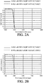
- FIG. 2A illustrates an optical characteristic of the dichroic PBS 103 to P-polarized light and S-polarized light.
- the abscissa axis represents a wavelength (nm) and the ordinate axis represents a reflectance (transmittance).
- the dichroic PBS 103 has a polarization separation characteristic of reflecting the S-polarized light and of transmitting the P-polarized light for the blue light, and also has a dichroic characteristic of transmitting green light and red light other than the blue light.
- the excitation light from the light source 101 enters as the S-polarized light the dichroic PBS 103 and is reflected on it.
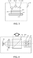
- FIG. 3 illustrates a configuration of the wavelength conversion element 105.
- the wavelength conversion element 105 includes, in order from the incident side of the excitation light, a wavelength conversion layer (wavelength converter) 1051, a dichroic mirror 1052, a quarter wavelength plate (polarization rotator) 1053, and a reflective diffusion plate (reflector) 1054 as a substrate.
- the wavelength conversion layer 1051 is made of a wavelength conversion material including a quantum rod, absorbs only the S-polarized light component in the excitation light, converts the wavelength of the light, and emits yellow light (red light and green light) that is the fluorescent light as the S-polarized light.
- the quantum rod converts the wavelength of part of the excitation light while maintaining the S-polarized light to generate the fluorescent light (second light).
- the dichroic mirror 1052 transmits the blue light and reflects the red light and green light.
- the fluorescent light as the S-polarized light that travels from the wavelength conversion layer 1051 to the dichroic PBS 103 passes through the condensing optical system 104 and the dichroic PBS 103 and travels (is emitted) to the outside of the light source unit 100.
- the illumination optical system for a projector described later is provided outside the light source unit.
- the fluorescent light that has passed from the wavelength conversion layer 1051 to the quarter wavelength plate 1053 and traveled toward the dichroic mirror 1052 is reflected by the dichroic mirror 1052, passes through the wavelength conversion layer 1051, transmits the condensing optical system 104 and the dichroic PBS 103, and travels to the outside of the light source unit 100.
- the excitation light having an unconverted wavelength in the wavelength conversion layer 1051 passes through the dichroic mirror 1052, passes through the quarter wavelength plate 1053, is reflected by the reflecting plate 1054, again passes through the quarter wavelength plate 1053, passes through the dichroic mirror 1052, and enters the wavelength conversion layer 1051.
- the unconverted light passes through the quarter wavelength plate 1053 twice, and its polarization direction is rotated by 90°, and the unconverted light becomes the P-polarized light.
- the unconverted light is emitted from the wavelength conversion layer 1051 with its wavelength unconverted, passes through the condensing optical system 104 and the dichroic PBS 103, and travels to the outside of the light source unit 100. Since the dichroic PBS 103 transmits the blue P-polarized light, this unconverted light also travels to the outside of the light source unit 100.
- the reflective diffusion plate 1054 may simply be a mirror, but may serve as a reflective diffusion plate configured to diffuse the unconverted light as long as the polarization state of the unconverted light is maintained.
- the above configuration realizes a light source unit that can emit both the fluorescent light and the unconverted light as linear polarization light (S-polarized light and P-polarized light).
- the S-polarized light and the P-polarized light described above may be the P-polarized light and the S-polarized light, respectively.
- the dichroic PBS 103 having the optical characteristic illustrated in FIG. 2B may be used (where the abscissa axis represents the wavelength (nm) and the ordinate axis represents the reflectance). Then, the excitation light from the light source 101 enters the dichroic PBS 103 as the P-polarized light and is reflected there.
- the wavelength conversion layer 1051 absorbs only the P-polarized light component in the excitation light, converts the wavelength, and emits the fluorescent light as the P-polarized light.
- This embodiment uses a quantum rod to generate the fluorescent light in the same polarization direction as the polarization direction of the excitation light, but may use an element other than the quantum rod as long as the element can provide a similar operation due to the fine structure. This is similarly applicable to other embodiments described later.
- the substrate of the wavelength conversion element 105 may be a rotating wheel rotationally driven by a motor. This is similarly applicable to the other embodiments described later.
- FIG. 4 illustrates a configuration of a light source unit 100A according to a second embodiment of the present invention.
- This embodiment transmits the excitation light from the light source (light emitting element) 101 through a dichroic PBS (polarization beam splitter) 201 as an optical element, while the fluorescent light and the unconverted light from the wavelength conversion element 105 are reflected by the dichroic PBS 201 and emitted to the outside of the light source unit.
- a dichroic PBS polarization beam splitter
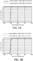
- the dichroic PBS 201 has an optical characteristic illustrated in FIG. 5A .
- the abscissa axis represents the wavelength (nm) and the ordinate axis represents the reflectance.
- the dichroic PBS 201 transmits the excitation light as the P-polarized light from the light source 101 through the dichroic PBS 201 and causes the excitation light to enter the wavelength conversion element 105.
- the wavelength conversion element 105 generates the fluorescent light of the P-polarized light by a quantum rod and emits the unconverted light as the S-polarized light.
- the fluorescent light and the unconverted light are reflected by the dichroic PBS 103 and travel to the outside of the light source unit 100A.
- This configuration can realize a light source unit configured to emit both the fluorescent light and the unconverted light as the linear polarization light (the P-polarized light and the S-polarized light).
- the P-polarized light and the S-polarized light may be the S-polarized light and the P-polarized light, respectively.
- a dichroic PBS 201 having the optical characteristic illustrated in FIG. 5B may be used (where the abscissa axis represents the wavelength (nm) and the ordinate axis represents the reflectance).
- the excitation light from the light source 101 enters as the S-polarized light the dichroic PBS 201 and is reflected there.
- the wavelength conversion layer 1051 absorbs only the S-polarized light component in the excitation light, converts the wavelength, and emits the fluorescent light of the S-polarized light.
- the fluorescent light and unconverted light (blue P-polarized light) pass through the dichroic PBS 103.
- FIG. 6 illustrates a configuration of a wavelength conversion element 105A used for a light source unit according to third embodiment of the present invention.
- the configuration of the light source unit other than the wavelength conversion element 105A is the same as that of first embodiment ( FIG. 1 ).
- the wavelength conversion element 105A includes, in order from the incident side of the excitation light, a wavelength conversion layer 301, the dichroic mirror 1052, the quarter wavelength plate 1053, and the reflective diffusion plate 1054.
- the wavelength conversion layer 301 is made of a wavelength conversion material including a quantum rod, absorbs the P-polarized light component in the incident excitation light, converts the wavelength of the light, and emits the fluorescent light as the P-polarized light.
- the S-polarized light component in the excitation light has a wavelength unconverted by the wavelength conversion layer 301, passes through the dichroic mirror 1052 and the quarter wavelength plate 1053, and is reflected and diffused by the reflective diffusion plate 1054.
- the reflected and diffused unconverted light again passes through the quarter wavelength plate 1053 and the dichroic mirror 1052, and enters the wavelength conversion layer 301.
- the unconverted light is converted into the P-polarized light by passing through the quarter wavelength plate twice, and thus the wavelength of part of the unconverted light is converted after entering the wavelength conversion layer 1051 again.
- the fluorescent light as the P-polarized light is generated, and the fluorescent light passes through the dichroic PBS 103 and travels to the outside of the light source unit.
- This configuration can realize a light source unit that can emit both the fluorescent light and the unconverted light as the linear polarization light (P-polarized light and P-polarized light).
- the polarization directions of the fluorescent light and the unconverted light can be aligned with each other.
- the S-polarized light and the P-polarized light in this embodiment may be the P-polarized light and the S-polarized light, respectively.
- the excitation light may transmit through the dichroic PBS 103 and enter the wavelength conversion element 105A, and the fluorescent light and the unconverted light from the wavelength conversion element 105A may be reflected by the dichroic PBS 103.
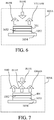
- FIG. 7 illustrates a configuration of a wavelength conversion element 105B used for a light source unit according to a fourth embodiment of the present invention.
- the configuration of the light source unit other than the wavelength conversion element 105B is the same as that of first embodiment ( FIG. 1 ).
- the wavelength conversion element 105B includes, in order from the incident side of the excitation light, a wavelength conversion layer 401, the dichroic mirror 1052, the quarter wavelength plate 1053, and the reflective diffusion plate 1054.
- the wavelength conversion layer 401 is made of a wavelength conversion material that includes a red quantum rod that converts the wavelength of the blue light and emits the red light as the fluorescent light and a green quantum rod that converts the wavelength of the blue light and emits the green light as the fluorescent light.
- the red quantum rod and the green quantum rod are arranged such that their longitudinal directions or the polarization directions of the red light and the green light emitted from them are orthogonal to each other.
- Part of the excitation light incident as the S-polarized light on and reflected by the dichroic PBS 103 has a converted wavelength and is turned into red light while its S-polarized light is maintained in the wavelength conversion layer 401 by the red quantum rod.
- the unconverted light passes through the dichroic mirror 1052 and the quarter wavelength plate 1053, and is reflected by the reflective diffusion plate 1054, passes through the quarter wavelength plate 1053 again and the dichroic mirror 1052, and enters the wavelength conversion layer 401.
- the unconverted light is converted into the P-polarized light by passing through the quarter wavelength plate 1053 twice before and after reflection (forward and return paths) on the reflective diffusion plate 1054, so that it is turned into the green light as the P-polarized light by the wavelength conversion by the green quantum rod in the wavelength conversion layer 401.
- the unconverted light that has a wavelength unconverted in the return path is emitted as the P-polarized light from the wavelength conversion element 105B.
- the red light as the S-polarized light, the green light as the P-polarized light, and the unconverted light as P-polarized light all pass through the dichroic PBS 103 and travel to the outside of the light source unit.
- This configuration can realize a light source unit that can emit both the fluorescent light and the unconverted light as the linear polarization light while making the polarization directions of the red light and the green light as the fluorescent light different from each other.
- the S-polarized light and the P-polarized light in this embodiment may be the P-polarized light and the S-polarized light, respectively.
- the excitation light may transmit through the dichroic PBS 103 and enter the wavelength conversion element 105B, and the fluorescent light and the unconverted light from the wavelength conversion element 105B may be reflected by the dichroic PBS 103.
- FIG. 9 illustrates a configuration of a wavelength conversion element 105C for a light source unit according to a fifth embodiment of the present invention.
- the configuration of the light source unit other than the wavelength conversion element 105C is the same as that of the first embodiment ( FIG. 1 ).
- the wavelength conversion element 105C includes, in order from the incident side of the excitation light, a wavelength conversion layer 5011, a wavelength selective polarization rotator (polarization rotator) 5012, and a reflective diffusion plate 5013.
- the excitation light enters as the S-polarized light the dichroic PBS 103 and is reflected there, and enters the wavelength conversion layer 5011.
- the wavelength conversion layer 5011 is made of a wavelength conversion material including a quantum rod, absorbs part of the excitation light as the S-polarized light, converts the wavelength of the light, and generates the fluorescent light as the S-polarized light.
- the wavelength selective polarization rotator 5012 is an element that rotates only the polarization direction of the unconverted light (blue light) that passes through it twice and does not rotate the polarization direction of the fluorescent light (red light and green light).
- the wavelength selective polarization rotator 5012 can be manufactured by laminating a plurality of retardation plates in the axial direction (the passing direction of light) and by bonding the plurality of retardation plates with different thicknesses.
- the fluorescent light and the unconverted light that have passed through the wavelength selective polarization rotator 5012 are reflected and diffused by the reflective diffusion plate 5013, pass through the wavelength selective polarization rotator 5012 again, and enter the wavelength conversion layer 5014. At this time, only the polarization direction of the unconverted light is rotated. Thereby, the fluorescent light as the S-polarized light and the unconverted light as the P-polarized light are emitted from the wavelength conversion element 105C. Both the fluorescent light as the S-polarized light and the unconverted light as the P-polarized light pass through the dichroic PBS 103 and travel to the outside of the light source unit.
- This embodiment realizes a light source unit that can emit both the fluorescent light and the unconverted light as the linear polarization light (S-polarized light and P-polarized light).
- the S-polarization light and the P-polarization light in this embodiment may be the P-polarized light and the S-polarized light, respectively.
- the excitation light may transmit through the dichroic PBS 103 and enter the wavelength conversion element 105C, and the fluorescent light and the unconverted light from the wavelength conversion element 105C may be reflected by the dichroic PBS 103.
- the wavelength of the excitation light may be converted not in the forward path but in the return path, or as in the fourth embodiment, a quantum rod may be used to generate the converted light of in a different polarization direction depending on colors.
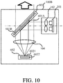
- FIG. 10 illustrates a configuration of a light source unit 100B according to a sixth embodiment of the present invention.
- This embodiment uses, in place of the dichroic PBS 103 used in the first embodiment, a partial dichroic mirror 601 as an optical element and a wavelength conversion element 602.
- the configuration of the light source unit other than the partial dichroic mirror 601 and the wavelength conversion element 602 is the same as that of the first embodiment ( FIG. 1 ).
- the wavelength conversion element 602 includes a wavelength conversion layer 6021 and a reflective diffusion plate 6022 in order from the incident side of the excitation light.
- the partial dichroic mirror 601 is divided into a first region 601A which reflects the blue light and transmits the red light and the green light, and a second region 601B which transmits all of the red light, the green light, and the blue light.
- the excitation light (blue light) as the linear polarization light from the light source 101 is reflected by the first region 601A and guided to the wavelength conversion element 602.
- the wavelength conversion layer 6021 in the wavelength conversion element 602 is made of a wavelength conversion material including a quantum rod, and converts a wavelength of the incident excitation light to generate the fluorescent light as the linear polarization light having the same polarization direction as the excitation light.
- Part of the excitation light passes through the wavelength conversion layer 6021 without being converted by the wavelength conversion layer 6021, and is reflected and diffused by the reflection diffuser plate 6022.
- the reflected and diffused unconverted light again enters the wavelength conversion layer 6021, and the wavelength of part of it is converted and the light is turned into the fluorescent light as the linear polarization light while the polarization direction is maintained in the same way as in the forward path.
- the other part is emitted as the unconverted light from the wavelength conversion layer 6021.
- the wavelength conversion element 602 emits the fluorescent light and unconverted light as the linear polarization light having the same polarization direction.
- the unconverted light other than the unconverted light reflected by the first region 601A and the fluorescent light transmit through the partial dichroic mirror 601 (first and second regions 601A and 601B) and travel to the outside of the light source unit 100B.
- This configuration realizes a light source unit that can emit both the fluorescent light and the unconverted light as the linear polarization light having the same polarization direction.
- the second region 601B may be a region that reflects all of the red light, the green light, and the blue light
- the first region 601A may be a region that transmits only the blue light.
- the blue light as the linear polarization light from the light source 101 transmits through the first region 601A and is guided to the wavelength conversion element 602, and the fluorescent light and the unconverted light from the wavelength conversion element 602 are reflected by the partial dichroic mirror 601 and travel to the outside of the light source unit 100B.
- This configuration is similarly applicable to sixth and seventh embodiments described below.
- the excitation light is nonpolarized light including both the P-polarization and the S-polarization.
- the wavelength conversion layer 6021 is sufficiently thick enough to convert all the S-polarized light components in the incident excitation light into the fluorescent light as the S-polarized light. Thereby, the fluorescent light as the S-polarized light and the unconverted light as the P-polarized light are emitted from the wavelength conversion element 602.
- This configuration realizes a light source unit that can emit both the fluorescent light and the unconverted light as the linear polarization light (S-polarized light and P-polarized light).
- the fluorescent light and the unconverted light may be emitted as the linear polarization light in the same polarization direction from the light source unit by generating the fluorescent light as P-polarized light.
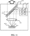
- FIG. 11 illustrates a configuration of a light source unit 100C according to an eighth embodiment of the present invention.
- the light source unit 100C has the same configuration as that of the seventh embodiment, a wavelength conversion layer 801 is provided instead of the wavelength conversion layer 6021 in the wavelength conversion element 602 according to the seventh embodiment, and an element 602A having the reflective diffusion plate 6022 is used.
- the quantum rods for red and the quantum rods for green are disposed in the wavelength conversion layer 801 so that their longitudinal directions are orthogonal to each other. However, the concentration of the red quantum rods is sufficiently higher than that of the green quantum rods.
- the red light in this embodiment may be the P-polarized light.
- the green light and the unconverted light have the polarization directions orthogonal to the polarization direction of the red light.
- the concentration of the green quantum rods may be sufficiently higher than that of the red quantum rods.
- FIG. 12 illustrates a configuration of a light source unit 100D according to a ninth embodiment according to the present invention.
- a light source 901 is a laser diode as a light emitting element that outputs ultraviolet light (first light) as the excitation light.
- the ultraviolet light emitted from a light source 901 is converted into parallel light by a collimating optical system 902, reflected by a dichroic mirror 903 as an optical element, condensed by a condensing optical system 904, and irradiated onto a wavelength conversion element 905.
- the wavelength conversion element 905 includes a wavelength conversion layer 9051 and a reflective plate 9052 in order from the incident side of the excitation light.
- the wavelength conversion layer 9051 is made of a wavelength conversion material including a quantum rod, absorbs the excitation light as the linear polarization light in a predetermined polarization direction, and emits the fluorescent light as the linear polarization light in a predetermined polarization direction without changing the polarization direction.
- the wavelength conversion layer 9051 includes three types of quantum rods, such as a blue quantum rod that emits the blue fluorescent light (second light) by the wavelength conversion of the ultraviolet light, a green quantum rod that emits the green fluorescent light (third light), and a red quantum rod that emits the red fluorescent light (fourth light).
- the longitudinal directions (polarization directions of fluorescent light) of these three types of quantum rods coincide with the polarization direction of the excitation light.
- a spectrum of the light emitted from the wavelength conversion element 905 becomes a spectrum including three colors of red, green, and blue, as illustrated in FIG. 13 , or white linear polarization light as a whole.
- the types of quantum rods included in the wavelength conversion layer 9051 are not limited to the above three types, and the wavelength conversion layer 9051 may include more than three types of quantum rods.
- the component directed to the reflective plate 9052 is reflected by the reflection plate 9052, transmits through the wavelength conversion layer 9051, and travels to the dichroic mirror 903.
- the dichroic mirror 903 has a characteristic of transmitting visible light, and the fluorescent light passes through the dichroic mirror 903 as it is and travels to the outside of the light source unit 100D.
- This configuration can realize the light source unit 100D that generates white light as the linear polarization light.
- the excitation light may transmit through the dichroic mirror 903 and enter the wavelength conversion element 905, and the fluorescent light from the wavelength conversion element 905 may be reflected by the dichroic mirror 903 and emitted from the light source unit.
- FIG. 14 illustrates a configuration of a light source unit 100E according to tenth embodiment of the present invention.
- This embodiment disposes a rotatable half wavelength plate (color adjustment element) 1001 just after the light source 901 in the same configuration as that of ninth embodiment and changes the polarization direction of the excitation light as the linear polarization light.
- a wavelength converter 905A in this embodiment includes a wavelength conversion layer 10051 in place of the wavelength conversion layer 9051 in the wavelength conversion element 905 according to the ninth embodiment, and further includes a reflective plate 9052.
- the wavelength conversion layer 10051 includes three types of quantum rods, such as a blue quantum rod that emits the blue fluorescent light by the wavelength conversion of the ultraviolet light, a green quantum rod that emits the green fluorescent light, and a red that emits the red fluorescent light.
- a blue quantum rod that emits the blue fluorescent light by the wavelength conversion of the ultraviolet light
- a green quantum rod that emits the green fluorescent light
- a red that emits the red fluorescent light.
- the longitudinal direction (polarization direction of the blue fluorescent light) of the blue quantum rod in the wavelength conversion layer 10051 is orthogonal to the longitudinal directions of the green quantum rod and the red quantum rod.
- the component having a polarization direction parallel to the longitudinal direction of the blue quantum rod receives the wavelength conversion by the blue quantum rod and turns into the blue light as the linear polarization light.
- the components in the excitation light which are parallel to the longitudinal directions of the green quantum rod and the red quantum rod receive the wavelength conversion by the green quantum rod and the red quantum rod and turn into the green light and red light as the linear polarization light, respectively.
- white light is generated while the polarization direction of the blue light and the polarization directions of the green light and red light are different from each other.
- a ratio can be changed of a component of the polarization direction of the excitation light entering the wavelength conversion layer 10051 which is parallel to the longitudinal direction of the blue quantum rod and a component of it which is parallel to the longitudinal directions of the green and red quantum rods.
- the chromaticity of the fluorescent light emitted from the wavelength conversion layer 10051 can be adjusted, and the tint of the white light can be adjusted.
- This embodiment makes different the longitudinal direction of the blue quantum rod from the longitudinal directions of the green quantum rod and the red quantum rod, but the color of the quantum rod may not be blue which has a polarization direction different from the polarization directions of the two other color light fluxes.
- the excitation light transmits through the dichroic mirror 903 and enters the wavelength conversion element 905, and the fluorescent light from the wavelength conversion element 905 is reflected by the dichroic mirror 903 and emitted from the light source unit 100E.
- FIG. 16 illustrates a configuration of a projector as an image projection apparatus using the light source unit 100 described in the first embodiment.
- the projector includes a light source unit 100, an illumination optical system 1101, a color separating and guiding optical system 1102, light modulation elements 1103R, 1103G, and 1103B, a color combining cross dichroic prism 1104, and a projection optical system 1105.
- any one of the light source units 100A to 100D described in the second and tenth embodiments may be used.
- the light modulation elements 1103R, 1103G, and 1103B are made of transmission type liquid crystal display elements, and configured to modulate the incident red light, green light, and blue light based on the image signal input to the projector.
- An incident side polarizing plate 1106 is disposed on the light incident side of each of the light modulation elements 1103R, 1103G, and 1103B, and an exit side polarizing plate 1107 is disposed on the light exit side of the light modulation elements 1103R, 1103G, and 1103B.
- FIG. 16 illustrates the transmission type liquid crystal display element used as a light modulation element
- a reflection type liquid crystal display element or a digital micro mirror device may be used as the light modulation element.
- the illumination optical system 1101 includes a first lens array 11011, a second lens array 11012, and a condenser lens 11013.
- the first lens array 11011 has a plurality of lens cells for dividing the light from the light source unit 100 into a plurality of partial light beams (or fluxes).
- the plurality of lens cells are arranged in a matrix on a plane orthogonal to the optical axis (illumination optical axis) in the illumination optical system 1101.
- the second lens array 11012 has a plurality of lens cells one by one corresponding to the plurality of lens cells of the first lens array 11011.
- the plurality of lens cells are also arranged in a matrix on a plane orthogonal to the illumination optical axis.
- the second lens array 11012 forms an image of each lens cell of the first lens array 11011 near the light modulation elements 1103R, 1103G, and 1103B, together with the condenser lens 11013.
- the condenser lens 11013 condenses the plurality of partial light fluxes from the second lens array 11012 and superimposes them on the light modulation elements 1103R, 1103G, and 1103B.
- the first lens array 11011, the second lens array 11012, and the condenser lens 11013 constitute an integrator optical system that makes uniform the intensity distribution of the light from the light source unit 100.
- the color separating and guiding optical system 1102 includes dichroic mirrors 11021 and 11022, mirrors 11023, 11024, and 11025, and relay lenses 11026 and 11027.
- the color separating and guiding optical system 1102 separates the white light from the illumination optical system 1101 into the red light, the green light, and the blue light, and the light modulation elements 1103R, 1103G, and 1103B corresponding to these red light, green light, and blue light, respectively.
- Condenser lenses 11028R, 11028G, and 11028B are disposed between the color separating and guiding optical system 1102 and the light modulation elements 1103R, 1103G, and 1103B.
- the dichroic mirror 11021 transmits the red light and reflects the green light and blue light.
- the dichroic mirror 11022 reflects the green light and transmits the blue light.
- the mirror 11023 reflects the red light.
- the mirrors 11024 and 11025 reflect blue light.
- the red light that has transmitted through the dichroic mirror 11021 is reflected by the mirror 11023, is condensed by the condensing lens 11028R, and enters the red light modulation element 1103R.
- the green light reflected by the dichroic mirror 11021 is further reflected by the dichroic mirror 11022, is condensed by the condensing lens 11028G, and enters the green light modulation element 1103G.
- the blue light that has transmitted through the dichroic mirror 11022 passes through the relay lens 11026, the mirror 11024 on the incident side, the relay lens 11027, and the mirror 11025 on the exit side, is condensed by the condensing lens 11028B, and enters the light modulation element 11028B.
- the cross dichroic prism 1104 combines the red, green and blue image light fluxes emitted from the light modulation elements 1103R, 1103G and 1103B with one another.
- the combined light emitted from the cross dichroic prism 1104 is enlarged and projected onto a projection surface such as a screen by the projection optical system 1105. Thereby, the projection image as a color image is displayed.
- Each embodiment can eliminate a polarization conversion element, and realize a light source apparatus with a high light utilization efficiency.
Landscapes
- Physics & Mathematics (AREA)
- General Physics & Mathematics (AREA)
- Optics & Photonics (AREA)
- Engineering & Computer Science (AREA)
- Multimedia (AREA)
- Projection Apparatus (AREA)
- Non-Portable Lighting Devices Or Systems Thereof (AREA)
- Video Image Reproduction Devices For Color Tv Systems (AREA)
Abstract
Description
- The present invention relates to a light source apparatus suitable for an image projection apparatus (projector).
- One light source apparatus for a projector includes, as disclosed in Japanese Patent Laid-Open No. ("
JP") 2015-106130 - The light source apparatus disclosed in
JP 2015-106130 - Then, a space is necessary to dispose the polarization conversion element, and the illumination optical system becomes larger. The Etendue of the illumination optical system becomes smaller, and the light utilization efficiency (illumination efficiency) lowers.
- The present invention provides a light source apparatus that can realize a high light utilization efficiency using a wavelength conversion element.
- The present invention in its first aspect provides a light source apparatus as specified in any one of
claims 1 to 12. - The present invention in its second aspect provides an image projection apparatus as specified in claim 13.
- Further features of the present invention will become apparent from the following description of exemplary embodiments with reference to the attached drawings.
-
-
FIG. 1 illustrates a configuration of a light source apparatus according to a first embodiment of the present invention. -
FIGs. 2A and 2B illustrate characteristics of a dichroic PBS according to the first embodiment. -
FIG. 3 illustrates a configuration of a wavelength conversion element in the first embodiment. -
FIG. 4 illustrates a configuration of a light source apparatus according to a second embodiment of the present invention. -
FIGs. 5A and 5B illustrate a characteristic of a dichroic PBS according to the second embodiment. -
FIG. 6 illustrates a configuration of a wavelength conversion element according to a third embodiment of the present invention. -
FIG. 7 illustrates a configuration of a wavelength conversion element according to a fourth embodiment of the present invention. -
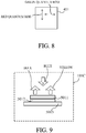
FIG. 8 illustrates an arrangement of quantum rods according to the fourth embodiment; -
FIG. 9 illustrates a configuration of a wavelength conversion element according to a fifth embodiment of the present invention. -
FIG. 10 illustrates a configuration of a light source apparatus according to a sixth embodiment of the present invention. -
FIG. 11 illustrates a configuration of a light source apparatus according to an eighth embodiment of the present invention. -
FIG. 12 illustrates a configuration of a light source apparatus according to a ninth embodiment of the present invention. -
FIG. 13 illustrates a spectrum of fluorescent light according to the ninth embodiment. -
FIG. 14 illustrates a configuration of a light source apparatus according to a tenth embodiment of the present invention. -
FIG. 15 illustrates an arrangement of quantum rods according to the tenth embodiment. -
FIG. 16 illustrates a configuration of a light source apparatus according to an eleventh embodiment of the present invention. - Referring now to the accompanying drawings, a description will be given of embodiments according to the present invention.
-
FIG. 1 illustrates a configuration of a light source apparatus (light source unit) 100 according to a first embodiment of the present invention. Alight source 101 includes blue laser diodes as a plurality of light emitting elements that emit laser beams as linear polarization light. Excitation light (first light) from thelight source 101 is converted into parallel light by a collimatingoptical system 102, is reflected by adichroic PBS 103 as an optical element, and is irradiated onto awavelength conversion element 105 by a condensingoptical system 104. This embodiment uses a blue laser diode as a light emitting element for thelight source 101, but may use any light emitting elements other than a laser diode as long as it emits the blue linear polarization light. -
FIG. 2A illustrates an optical characteristic of thedichroic PBS 103 to P-polarized light and S-polarized light. The abscissa axis represents a wavelength (nm) and the ordinate axis represents a reflectance (transmittance). Thedichroic PBS 103 has a polarization separation characteristic of reflecting the S-polarized light and of transmitting the P-polarized light for the blue light, and also has a dichroic characteristic of transmitting green light and red light other than the blue light. The excitation light from thelight source 101 enters as the S-polarized light thedichroic PBS 103 and is reflected on it. -
FIG. 3 illustrates a configuration of thewavelength conversion element 105. Thewavelength conversion element 105 includes, in order from the incident side of the excitation light, a wavelength conversion layer (wavelength converter) 1051, adichroic mirror 1052, a quarter wavelength plate (polarization rotator) 1053, and a reflective diffusion plate (reflector) 1054 as a substrate. Thewavelength conversion layer 1051 is made of a wavelength conversion material including a quantum rod, absorbs only the S-polarized light component in the excitation light, converts the wavelength of the light, and emits yellow light (red light and green light) that is the fluorescent light as the S-polarized light. In other words, the quantum rod converts the wavelength of part of the excitation light while maintaining the S-polarized light to generate the fluorescent light (second light). Thedichroic mirror 1052 transmits the blue light and reflects the red light and green light. - The fluorescent light as the S-polarized light that travels from the
wavelength conversion layer 1051 to thedichroic PBS 103 passes through the condensingoptical system 104 and thedichroic PBS 103 and travels (is emitted) to the outside of thelight source unit 100. The illumination optical system for a projector described later is provided outside the light source unit. The fluorescent light that has passed from thewavelength conversion layer 1051 to thequarter wavelength plate 1053 and traveled toward thedichroic mirror 1052 is reflected by thedichroic mirror 1052, passes through thewavelength conversion layer 1051, transmits the condensingoptical system 104 and thedichroic PBS 103, and travels to the outside of thelight source unit 100. - On the other hand, the excitation light having an unconverted wavelength in the wavelength conversion layer 1051 (hereinafter referred to as unconverted light) passes through the
dichroic mirror 1052, passes through thequarter wavelength plate 1053, is reflected by thereflecting plate 1054, again passes through thequarter wavelength plate 1053, passes through thedichroic mirror 1052, and enters thewavelength conversion layer 1051. At this time, the unconverted light passes through thequarter wavelength plate 1053 twice, and its polarization direction is rotated by 90°, and the unconverted light becomes the P-polarized light. Hence, the unconverted light is emitted from thewavelength conversion layer 1051 with its wavelength unconverted, passes through the condensingoptical system 104 and thedichroic PBS 103, and travels to the outside of thelight source unit 100. Since thedichroic PBS 103 transmits the blue P-polarized light, this unconverted light also travels to the outside of thelight source unit 100. - The
reflective diffusion plate 1054 may simply be a mirror, but may serve as a reflective diffusion plate configured to diffuse the unconverted light as long as the polarization state of the unconverted light is maintained. - The above configuration realizes a light source unit that can emit both the fluorescent light and the unconverted light as linear polarization light (S-polarized light and P-polarized light).
- The S-polarized light and the P-polarized light described above may be the P-polarized light and the S-polarized light, respectively. In other words, the
dichroic PBS 103 having the optical characteristic illustrated inFIG. 2B may be used (where the abscissa axis represents the wavelength (nm) and the ordinate axis represents the reflectance). Then, the excitation light from thelight source 101 enters thedichroic PBS 103 as the P-polarized light and is reflected there. Thewavelength conversion layer 1051 absorbs only the P-polarized light component in the excitation light, converts the wavelength, and emits the fluorescent light as the P-polarized light. - This embodiment uses a quantum rod to generate the fluorescent light in the same polarization direction as the polarization direction of the excitation light, but may use an element other than the quantum rod as long as the element can provide a similar operation due to the fine structure. This is similarly applicable to other embodiments described later.
- The substrate of the
wavelength conversion element 105 may be a rotating wheel rotationally driven by a motor. This is similarly applicable to the other embodiments described later. -
FIG. 4 illustrates a configuration of alight source unit 100A according to a second embodiment of the present invention. This embodiment transmits the excitation light from the light source (light emitting element) 101 through a dichroic PBS (polarization beam splitter) 201 as an optical element, while the fluorescent light and the unconverted light from thewavelength conversion element 105 are reflected by thedichroic PBS 201 and emitted to the outside of the light source unit. - The
dichroic PBS 201 has an optical characteristic illustrated inFIG. 5A . The abscissa axis represents the wavelength (nm) and the ordinate axis represents the reflectance. Thedichroic PBS 201 transmits the excitation light as the P-polarized light from thelight source 101 through thedichroic PBS 201 and causes the excitation light to enter thewavelength conversion element 105. Unlike first embodiment, thewavelength conversion element 105 generates the fluorescent light of the P-polarized light by a quantum rod and emits the unconverted light as the S-polarized light. The fluorescent light and the unconverted light are reflected by thedichroic PBS 103 and travel to the outside of thelight source unit 100A. - This configuration can realize a light source unit configured to emit both the fluorescent light and the unconverted light as the linear polarization light (the P-polarized light and the S-polarized light).
- The P-polarized light and the S-polarized light may be the S-polarized light and the P-polarized light, respectively. In other words, a
dichroic PBS 201 having the optical characteristic illustrated inFIG. 5B may be used (where the abscissa axis represents the wavelength (nm) and the ordinate axis represents the reflectance). In this case, the excitation light from thelight source 101 enters as the S-polarized light thedichroic PBS 201 and is reflected there. Thewavelength conversion layer 1051 absorbs only the S-polarized light component in the excitation light, converts the wavelength, and emits the fluorescent light of the S-polarized light. The fluorescent light and unconverted light (blue P-polarized light) pass through thedichroic PBS 103. -
FIG. 6 illustrates a configuration of awavelength conversion element 105A used for a light source unit according to third embodiment of the present invention. The configuration of the light source unit other than thewavelength conversion element 105A is the same as that of first embodiment (FIG. 1 ). - The
wavelength conversion element 105A includes, in order from the incident side of the excitation light, awavelength conversion layer 301, thedichroic mirror 1052, thequarter wavelength plate 1053, and thereflective diffusion plate 1054. Thewavelength conversion layer 301 is made of a wavelength conversion material including a quantum rod, absorbs the P-polarized light component in the incident excitation light, converts the wavelength of the light, and emits the fluorescent light as the P-polarized light. - The S-polarized light component in the excitation light has a wavelength unconverted by the
wavelength conversion layer 301, passes through thedichroic mirror 1052 and thequarter wavelength plate 1053, and is reflected and diffused by thereflective diffusion plate 1054. The reflected and diffused unconverted light again passes through thequarter wavelength plate 1053 and thedichroic mirror 1052, and enters thewavelength conversion layer 301. The unconverted light is converted into the P-polarized light by passing through the quarter wavelength plate twice, and thus the wavelength of part of the unconverted light is converted after entering thewavelength conversion layer 1051 again. As a result, the fluorescent light as the P-polarized light is generated, and the fluorescent light passes through thedichroic PBS 103 and travels to the outside of the light source unit. - Among the unconverted light that is not converted into the P-polarized light, the unconverted light which has an unconverted wavelength even after entering the
wavelength conversion layer 1051 again passes through thedichroic PBS 103 and goes out of the light source unit. - This configuration can realize a light source unit that can emit both the fluorescent light and the unconverted light as the linear polarization light (P-polarized light and P-polarized light). The polarization directions of the fluorescent light and the unconverted light can be aligned with each other.
- As described in the first embodiment, the S-polarized light and the P-polarized light in this embodiment may be the P-polarized light and the S-polarized light, respectively. As in the second embodiment, the excitation light may transmit through the
dichroic PBS 103 and enter thewavelength conversion element 105A, and the fluorescent light and the unconverted light from thewavelength conversion element 105A may be reflected by thedichroic PBS 103. -
FIG. 7 illustrates a configuration of a wavelength conversion element 105B used for a light source unit according to a fourth embodiment of the present invention. The configuration of the light source unit other than the wavelength conversion element 105B is the same as that of first embodiment (FIG. 1 ). - The wavelength conversion element 105B includes, in order from the incident side of the excitation light, a
wavelength conversion layer 401, thedichroic mirror 1052, thequarter wavelength plate 1053, and thereflective diffusion plate 1054. Thewavelength conversion layer 401 is made of a wavelength conversion material that includes a red quantum rod that converts the wavelength of the blue light and emits the red light as the fluorescent light and a green quantum rod that converts the wavelength of the blue light and emits the green light as the fluorescent light. As illustrated inFIG. 8 , the red quantum rod and the green quantum rod are arranged such that their longitudinal directions or the polarization directions of the red light and the green light emitted from them are orthogonal to each other. - Part of the excitation light incident as the S-polarized light on and reflected by the
dichroic PBS 103 has a converted wavelength and is turned into red light while its S-polarized light is maintained in thewavelength conversion layer 401 by the red quantum rod. At this time, as in the first embodiment, the unconverted light passes through thedichroic mirror 1052 and thequarter wavelength plate 1053, and is reflected by thereflective diffusion plate 1054, passes through thequarter wavelength plate 1053 again and thedichroic mirror 1052, and enters thewavelength conversion layer 401. The unconverted light is converted into the P-polarized light by passing through thequarter wavelength plate 1053 twice before and after reflection (forward and return paths) on thereflective diffusion plate 1054, so that it is turned into the green light as the P-polarized light by the wavelength conversion by the green quantum rod in thewavelength conversion layer 401. The unconverted light that has a wavelength unconverted in the return path is emitted as the P-polarized light from the wavelength conversion element 105B. The red light as the S-polarized light, the green light as the P-polarized light, and the unconverted light as P-polarized light all pass through thedichroic PBS 103 and travel to the outside of the light source unit. - This configuration can realize a light source unit that can emit both the fluorescent light and the unconverted light as the linear polarization light while making the polarization directions of the red light and the green light as the fluorescent light different from each other.
- As described in the first embodiment, the S-polarized light and the P-polarized light in this embodiment may be the P-polarized light and the S-polarized light, respectively. As in the second embodiment, the excitation light may transmit through the
dichroic PBS 103 and enter the wavelength conversion element 105B, and the fluorescent light and the unconverted light from the wavelength conversion element 105B may be reflected by thedichroic PBS 103. -
FIG. 9 illustrates a configuration of awavelength conversion element 105C for a light source unit according to a fifth embodiment of the present invention. The configuration of the light source unit other than thewavelength conversion element 105C is the same as that of the first embodiment (FIG. 1 ). - The
wavelength conversion element 105C according to this embodiment includes, in order from the incident side of the excitation light, awavelength conversion layer 5011, a wavelength selective polarization rotator (polarization rotator) 5012, and areflective diffusion plate 5013. The excitation light enters as the S-polarized light thedichroic PBS 103 and is reflected there, and enters thewavelength conversion layer 5011. Thewavelength conversion layer 5011 is made of a wavelength conversion material including a quantum rod, absorbs part of the excitation light as the S-polarized light, converts the wavelength of the light, and generates the fluorescent light as the S-polarized light. - Part of the fluorescent light generated in the
wavelength conversion layer 5011 and the unconverted light having the wavelength unconverted there enter the wavelengthselective polarization rotator 5012. The wavelengthselective polarization rotator 5012 is an element that rotates only the polarization direction of the unconverted light (blue light) that passes through it twice and does not rotate the polarization direction of the fluorescent light (red light and green light). The wavelengthselective polarization rotator 5012 can be manufactured by laminating a plurality of retardation plates in the axial direction (the passing direction of light) and by bonding the plurality of retardation plates with different thicknesses. - The fluorescent light and the unconverted light that have passed through the wavelength
selective polarization rotator 5012 are reflected and diffused by thereflective diffusion plate 5013, pass through the wavelengthselective polarization rotator 5012 again, and enter the wavelength conversion layer 5014. At this time, only the polarization direction of the unconverted light is rotated. Thereby, the fluorescent light as the S-polarized light and the unconverted light as the P-polarized light are emitted from thewavelength conversion element 105C. Both the fluorescent light as the S-polarized light and the unconverted light as the P-polarized light pass through thedichroic PBS 103 and travel to the outside of the light source unit. - This embodiment realizes a light source unit that can emit both the fluorescent light and the unconverted light as the linear polarization light (S-polarized light and P-polarized light).
- As described in the first embodiment, the S-polarization light and the P-polarization light in this embodiment may be the P-polarized light and the S-polarized light, respectively. As in the second embodiment, the excitation light may transmit through the
dichroic PBS 103 and enter thewavelength conversion element 105C, and the fluorescent light and the unconverted light from thewavelength conversion element 105C may be reflected by thedichroic PBS 103. - As in the third embodiment, the wavelength of the excitation light may be converted not in the forward path but in the return path, or as in the fourth embodiment, a quantum rod may be used to generate the converted light of in a different polarization direction depending on colors.
-
FIG. 10 illustrates a configuration of alight source unit 100B according to a sixth embodiment of the present invention. This embodiment uses, in place of thedichroic PBS 103 used in the first embodiment, a partialdichroic mirror 601 as an optical element and awavelength conversion element 602. The configuration of the light source unit other than the partialdichroic mirror 601 and thewavelength conversion element 602 is the same as that of the first embodiment (FIG. 1 ). - The
wavelength conversion element 602 includes awavelength conversion layer 6021 and areflective diffusion plate 6022 in order from the incident side of the excitation light. - The partial
dichroic mirror 601 is divided into afirst region 601A which reflects the blue light and transmits the red light and the green light, and asecond region 601B which transmits all of the red light, the green light, and the blue light. The excitation light (blue light) as the linear polarization light from thelight source 101 is reflected by thefirst region 601A and guided to thewavelength conversion element 602. Thewavelength conversion layer 6021 in thewavelength conversion element 602 is made of a wavelength conversion material including a quantum rod, and converts a wavelength of the incident excitation light to generate the fluorescent light as the linear polarization light having the same polarization direction as the excitation light. - Part of the excitation light passes through the
wavelength conversion layer 6021 without being converted by thewavelength conversion layer 6021, and is reflected and diffused by thereflection diffuser plate 6022. The reflected and diffused unconverted light again enters thewavelength conversion layer 6021, and the wavelength of part of it is converted and the light is turned into the fluorescent light as the linear polarization light while the polarization direction is maintained in the same way as in the forward path. The other part is emitted as the unconverted light from thewavelength conversion layer 6021. As a result, thewavelength conversion element 602 emits the fluorescent light and unconverted light as the linear polarization light having the same polarization direction. Among the fluorescent light and the unconverted light, the unconverted light other than the unconverted light reflected by thefirst region 601A and the fluorescent light transmit through the partial dichroic mirror 601 (first andsecond regions light source unit 100B. - This configuration realizes a light source unit that can emit both the fluorescent light and the unconverted light as the linear polarization light having the same polarization direction.
- The
second region 601B may be a region that reflects all of the red light, the green light, and the blue light, and thefirst region 601A may be a region that transmits only the blue light. At this time, the blue light as the linear polarization light from thelight source 101 transmits through thefirst region 601A and is guided to thewavelength conversion element 602, and the fluorescent light and the unconverted light from thewavelength conversion element 602 are reflected by the partialdichroic mirror 601 and travel to the outside of thelight source unit 100B. This configuration is similarly applicable to sixth and seventh embodiments described below. - According to a seventh embodiment of the present invention, in the light source unit having the same configuration as that in the sixth embodiment, the excitation light is nonpolarized light including both the P-polarization and the S-polarization. The
wavelength conversion layer 6021 is sufficiently thick enough to convert all the S-polarized light components in the incident excitation light into the fluorescent light as the S-polarized light. Thereby, the fluorescent light as the S-polarized light and the unconverted light as the P-polarized light are emitted from thewavelength conversion element 602. - This configuration realizes a light source unit that can emit both the fluorescent light and the unconverted light as the linear polarization light (S-polarized light and P-polarized light).
- The fluorescent light and the unconverted light may be emitted as the linear polarization light in the same polarization direction from the light source unit by generating the fluorescent light as P-polarized light.
-
FIG. 11 illustrates a configuration of alight source unit 100C according to an eighth embodiment of the present invention. In this embodiment, thelight source unit 100C has the same configuration as that of the seventh embodiment, awavelength conversion layer 801 is provided instead of thewavelength conversion layer 6021 in thewavelength conversion element 602 according to the seventh embodiment, and anelement 602A having thereflective diffusion plate 6022 is used. - Similar to the
wavelength conversion layer 401 described in the fourth embodiment (FIG. 7 ), the quantum rods for red and the quantum rods for green are disposed in thewavelength conversion layer 801 so that their longitudinal directions are orthogonal to each other. However, the concentration of the red quantum rods is sufficiently higher than that of the green quantum rods. - Even in this embodiment, similar to the seventh embodiment, all the S-polarized light components in the excitation light incident on the
wavelength conversion layer 801 are converted into the red fluorescent light as the S-polarized light. Part of the P-polarized light components in the incident excitation light is converted into the green fluorescent light as the P-polarized light. As a result, the red light as the S-polarized light, the green light as the P-polarized light, and the unconverted light as the P-polarized light are emitted from thewavelength conversion element 602A. - The red light in this embodiment may be the P-polarized light. In this case, the green light and the unconverted light have the polarization directions orthogonal to the polarization direction of the red light. Alternatively, the concentration of the green quantum rods may be sufficiently higher than that of the red quantum rods.
-
FIG. 12 illustrates a configuration of alight source unit 100D according to a ninth embodiment according to the present invention. Alight source 901 is a laser diode as a light emitting element that outputs ultraviolet light (first light) as the excitation light. The ultraviolet light emitted from alight source 901 is converted into parallel light by a collimatingoptical system 902, reflected by adichroic mirror 903 as an optical element, condensed by a condensingoptical system 904, and irradiated onto awavelength conversion element 905. - The
wavelength conversion element 905 includes awavelength conversion layer 9051 and areflective plate 9052 in order from the incident side of the excitation light. Thewavelength conversion layer 9051 is made of a wavelength conversion material including a quantum rod, absorbs the excitation light as the linear polarization light in a predetermined polarization direction, and emits the fluorescent light as the linear polarization light in a predetermined polarization direction without changing the polarization direction. - The
wavelength conversion layer 9051 includes three types of quantum rods, such as a blue quantum rod that emits the blue fluorescent light (second light) by the wavelength conversion of the ultraviolet light, a green quantum rod that emits the green fluorescent light (third light), and a red quantum rod that emits the red fluorescent light (fourth light). The longitudinal directions (polarization directions of fluorescent light) of these three types of quantum rods coincide with the polarization direction of the excitation light. When thewavelength conversion layer 9051 includes these three types of quantum rods, a spectrum of the light emitted from thewavelength conversion element 905 becomes a spectrum including three colors of red, green, and blue, as illustrated inFIG. 13 , or white linear polarization light as a whole. The types of quantum rods included in thewavelength conversion layer 9051 are not limited to the above three types, and thewavelength conversion layer 9051 may include more than three types of quantum rods. - Among the fluorescent light generated in the
wavelength conversion layer 9051, the component directed to thereflective plate 9052 is reflected by thereflection plate 9052, transmits through thewavelength conversion layer 9051, and travels to thedichroic mirror 903. Thedichroic mirror 903 has a characteristic of transmitting visible light, and the fluorescent light passes through thedichroic mirror 903 as it is and travels to the outside of thelight source unit 100D. - This configuration can realize the
light source unit 100D that generates white light as the linear polarization light. - Even in this embodiment, similar to the second embodiment, the excitation light may transmit through the
dichroic mirror 903 and enter thewavelength conversion element 905, and the fluorescent light from thewavelength conversion element 905 may be reflected by thedichroic mirror 903 and emitted from the light source unit. -
FIG. 14 illustrates a configuration of alight source unit 100E according to tenth embodiment of the present invention. This embodiment disposes a rotatable half wavelength plate (color adjustment element) 1001 just after thelight source 901 in the same configuration as that of ninth embodiment and changes the polarization direction of the excitation light as the linear polarization light. Awavelength converter 905A in this embodiment includes awavelength conversion layer 10051 in place of thewavelength conversion layer 9051 in thewavelength conversion element 905 according to the ninth embodiment, and further includes areflective plate 9052. - Similar to the
wavelength conversion layer 9051, thewavelength conversion layer 10051 includes three types of quantum rods, such as a blue quantum rod that emits the blue fluorescent light by the wavelength conversion of the ultraviolet light, a green quantum rod that emits the green fluorescent light, and a red that emits the red fluorescent light. However, as illustrated inFIG. 15 , the longitudinal direction (polarization direction of the blue fluorescent light) of the blue quantum rod in thewavelength conversion layer 10051 is orthogonal to the longitudinal directions of the green quantum rod and the red quantum rod. - Among the excitation light incident on the
wavelength conversion layer 10051, the component having a polarization direction parallel to the longitudinal direction of the blue quantum rod receives the wavelength conversion by the blue quantum rod and turns into the blue light as the linear polarization light. The components in the excitation light which are parallel to the longitudinal directions of the green quantum rod and the red quantum rod receive the wavelength conversion by the green quantum rod and the red quantum rod and turn into the green light and red light as the linear polarization light, respectively. As a result, white light is generated while the polarization direction of the blue light and the polarization directions of the green light and red light are different from each other. As the rotational position of thehalf wavelength plate 1001 is adjusted, a ratio can be changed of a component of the polarization direction of the excitation light entering thewavelength conversion layer 10051 which is parallel to the longitudinal direction of the blue quantum rod and a component of it which is parallel to the longitudinal directions of the green and red quantum rods. Thereby, the chromaticity of the fluorescent light emitted from thewavelength conversion layer 10051 can be adjusted, and the tint of the white light can be adjusted. - This embodiment makes different the longitudinal direction of the blue quantum rod from the longitudinal directions of the green quantum rod and the red quantum rod, but the color of the quantum rod may not be blue which has a polarization direction different from the polarization directions of the two other color light fluxes.
- Even in this embodiment, similar to the second embodiment, the excitation light transmits through the
dichroic mirror 903 and enters thewavelength conversion element 905, and the fluorescent light from thewavelength conversion element 905 is reflected by thedichroic mirror 903 and emitted from thelight source unit 100E. -
FIG. 16 illustrates a configuration of a projector as an image projection apparatus using thelight source unit 100 described in the first embodiment. The projector includes alight source unit 100, an illuminationoptical system 1101, a color separating and guidingoptical system 1102,light modulation elements dichroic prism 1104, and a projectionoptical system 1105. In place of thelight source unit 100, any one of thelight source units 100A to 100D described in the second and tenth embodiments may be used. - The
light modulation elements light modulation elements light modulation elements - While
FIG. 16 illustrates the transmission type liquid crystal display element used as a light modulation element, a reflection type liquid crystal display element or a digital micro mirror device may be used as the light modulation element. - The illumination
optical system 1101 includes afirst lens array 11011, asecond lens array 11012, and acondenser lens 11013. Thefirst lens array 11011 has a plurality of lens cells for dividing the light from thelight source unit 100 into a plurality of partial light beams (or fluxes). The plurality of lens cells are arranged in a matrix on a plane orthogonal to the optical axis (illumination optical axis) in the illuminationoptical system 1101. - The
second lens array 11012 has a plurality of lens cells one by one corresponding to the plurality of lens cells of thefirst lens array 11011. The plurality of lens cells are also arranged in a matrix on a plane orthogonal to the illumination optical axis. Thesecond lens array 11012 forms an image of each lens cell of thefirst lens array 11011 near thelight modulation elements condenser lens 11013. - The
condenser lens 11013 condenses the plurality of partial light fluxes from thesecond lens array 11012 and superimposes them on thelight modulation elements first lens array 11011, thesecond lens array 11012, and thecondenser lens 11013 constitute an integrator optical system that makes uniform the intensity distribution of the light from thelight source unit 100. - The color separating and guiding
optical system 1102 includesdichroic mirrors relay lenses optical system 1102 separates the white light from the illuminationoptical system 1101 into the red light, the green light, and the blue light, and thelight modulation elements Condenser lenses optical system 1102 and thelight modulation elements - The
dichroic mirror 11021 transmits the red light and reflects the green light and blue light. Thedichroic mirror 11022 reflects the green light and transmits the blue light. Themirror 11023 reflects the red light. Themirrors - The red light that has transmitted through the
dichroic mirror 11021 is reflected by themirror 11023, is condensed by the condensinglens 11028R, and enters the redlight modulation element 1103R. The green light reflected by thedichroic mirror 11021 is further reflected by thedichroic mirror 11022, is condensed by the condensinglens 11028G, and enters the greenlight modulation element 1103G. The blue light that has transmitted through thedichroic mirror 11022 passes through therelay lens 11026, themirror 11024 on the incident side, therelay lens 11027, and themirror 11025 on the exit side, is condensed by the condensing lens 11028B, and enters the light modulation element 11028B. - The cross
dichroic prism 1104 combines the red, green and blue image light fluxes emitted from thelight modulation elements dichroic prism 1104 is enlarged and projected onto a projection surface such as a screen by the projectionoptical system 1105. Thereby, the projection image as a color image is displayed. - Each embodiment can eliminate a polarization conversion element, and realize a light source apparatus with a high light utilization efficiency.
- While the present invention has been described with reference to exemplary embodiments, it is to be understood that the invention is not limited to the disclosed exemplary embodiments. The scope of the following claims is to be accorded the broadest interpretation so as to encompass all such modifications and equivalent structures and functions.
Claims (13)
- A light source apparatus (100) comprising:a light emitting element (101) configured to emit first light;a wavelength conversion element (105) configured to convert part of the first light into second light having a wavelength different from that of the first light, and to emit the second light and unconverted light that is the first light which is not converted into the second light; andan optical element (103) configured to cause the first light to enter the wavelength conversion element, and the second light and the unconverted light to travel in a direction different from a direction of the light emitting element,characterized in that the wavelength conversion element emits the second light and the unconverted light as linear polarization light.
- The light source apparatus according to claim 1, characterized in that the wavelength conversion element includes a quantum rod.
- The light source apparatus according to claim 1, characterized in that the wavelength conversion element includes, from an incident side of the first light, at least a wavelength converter configured to convert the part of the first light into the second light, and a reflector configured to reflect the unconverted light.
- The light source apparatus according to claim 3, characterized in that the reflector diffuses the unconverted light.
- The light source apparatus according to claim 1 or 2, characterized in that each of the first light, the second light, and the unconverted light is the linear polarization light,
wherein the optical element reflects the first light and transmits the second light and the unconverted light, or transmits the first light and reflects the second light and the unconverted light. - The light source apparatus according to claim 4 or 5, further comprising, between the wavelength converter and the reflector, a polarization rotator (1053) configured to rotate a polarization direction of the unconverted light that passes through the wavelength converter, is reflected by the reflector, and passes through the wavelength converter again so that the polarization direction of the unconverted light is different from a polarization direction of the first light.
- The light source apparatus according to claim 6, further comprising a dichroic mirror (1052) configured to reflect the second light and to transmit the unconverted light, between the wavelength converter and the polarization rotator.
- The light source apparatus according to claim 6, characterized in that the polarization rotator (1053) does not rotate the polarization direction of the second light that is generated by the wavelength converter and reflected by the reflector and passes through the wavelength converter again.
- The light source apparatus according to any one of claims 1 to 4, characterized in that the optical element includes:a first region (601A) configured to reflect the first light and to transmit the second light and the unconverted light; anda second region (601B) configured to transmit the first light, the second light, and the unconverted light, orthat the optical element includes:a first region (601A) configured to transmit the first light and to reflect the second light and the unconverted light; anda second region (601B) configured to reflect the first light, the second light, and the unconverted light.
- A light source apparatus (100) comprising:a light emitting element (101) configured to emit first light;a wavelength conversion element (105) configured to convert the first light into second light, third light and fourth light having wavelengths different from a wavelength of the first light and from one another; andan optical element (103) configured to cause the first light to enter the wavelength conversion element, and the second light, the third light, and the fourth light to travel in a direction different from that of the light emitting element,characterized in that the wavelength conversion element emits each of the second light, the third light, and the fourth light as linear polarization light.
- The light source apparatus according to claim 10, characterized in that the wavelength conversion element includes a quantum rod.
- The light source apparatus according to claim 10 or 11, further comprising a color adjustment element configured to rotate and change a ratio among the second light, the third light, and the fourth light and disposed between the light emitting element and the wavelength conversion element.
- An image projection apparatus comprising:a light source apparatus (100) according to any one of claims 1 to 12; anda light modulation element (1103R, 1103G, 1103B) configured to modulate light from the light source apparatus,wherein the image projection apparatus is configured to project image light from the light modulation element onto a projection surface.
Applications Claiming Priority (1)
| Application Number | Priority Date | Filing Date | Title |
|---|---|---|---|
| JP2018094136A JP7106349B2 (en) | 2018-05-15 | 2018-05-15 | Light source device and image projection device |
Publications (2)
| Publication Number | Publication Date |
|---|---|
| EP3570106A1 true EP3570106A1 (en) | 2019-11-20 |
| EP3570106B1 EP3570106B1 (en) | 2022-04-20 |
Family
ID=66483911
Family Applications (1)
| Application Number | Title | Priority Date | Filing Date |
|---|---|---|---|
| EP19173786.5A Not-in-force EP3570106B1 (en) | 2018-05-15 | 2019-05-10 | Light source apparatus and image projection apparatus |
Country Status (4)
| Country | Link |
|---|---|
| US (1) | US11300861B2 (en) |
| EP (1) | EP3570106B1 (en) |
| JP (1) | JP7106349B2 (en) |
| CN (1) | CN110488561B (en) |
Families Citing this family (8)
| Publication number | Priority date | Publication date | Assignee | Title |
|---|---|---|---|---|
| JP7543819B2 (en) * | 2019-12-02 | 2024-09-03 | 株式会社リコー | Light source device and image projection device |
| CN212112106U (en) * | 2020-04-20 | 2020-12-08 | 深圳光峰科技股份有限公司 | A light guide element and light source device |
| CN111412436A (en) * | 2020-05-19 | 2020-07-14 | 佛山一长激光科技有限公司 | Laser lighting device |
| TWI786470B (en) * | 2020-10-14 | 2022-12-11 | 中強光電股份有限公司 | Display unit and projection apparatus |
| JP2022098642A (en) * | 2020-12-22 | 2022-07-04 | ウシオ電機株式会社 | Light source device and projector |
| CN112815273B (en) * | 2020-12-31 | 2025-03-21 | 万民 | A light emitting device |
| CN115437200B (en) * | 2021-06-03 | 2025-03-18 | 苏州佳世达光电有限公司 | Light source module |
| JP7571754B2 (en) * | 2022-03-16 | 2024-10-23 | カシオ計算機株式会社 | Light source device and projection device |
Citations (6)
| Publication number | Priority date | Publication date | Assignee | Title |
|---|---|---|---|---|
| WO2014024218A1 (en) * | 2012-08-06 | 2014-02-13 | パナソニック株式会社 | Fluorescent optical element, method for manufacturing same and light source device |
| US20140240676A1 (en) * | 2013-02-27 | 2014-08-28 | Barco N.V. | Light valve projector with laser-phosphor light converter |
| JP2015106130A (en) | 2013-12-02 | 2015-06-08 | セイコーエプソン株式会社 | Lighting device and projector |
| CN102722074B (en) * | 2012-03-02 | 2015-07-29 | 深圳市光峰光电技术有限公司 | Polarized light light-emitting device, light-emitting device and projector |
| JP2016145881A (en) * | 2015-02-06 | 2016-08-12 | セイコーエプソン株式会社 | Wavelength conversion element, lighting device and projector |
| WO2016184522A1 (en) * | 2015-05-21 | 2016-11-24 | Barco Nv | Polarized wavelength conversion wheel |
Family Cites Families (24)
| Publication number | Priority date | Publication date | Assignee | Title |
|---|---|---|---|---|
| JP5527571B2 (en) * | 2008-09-30 | 2014-06-18 | カシオ計算機株式会社 | Light emitting device, light source device, and projector using the light source device |
| JP2010204333A (en) * | 2009-03-03 | 2010-09-16 | Seiko Epson Corp | Projector |
| JP2012108486A (en) * | 2010-10-21 | 2012-06-07 | Panasonic Corp | Light source device and image display |
| JP2012113224A (en) * | 2010-11-26 | 2012-06-14 | Sanyo Electric Co Ltd | Illuminating device and projection type image displaying device |
| WO2013167152A1 (en) * | 2012-05-09 | 2013-11-14 | Merck Patent Gmbh | Three dimensional display system based on fluorescence emission of nanorods |
| JP2013250285A (en) * | 2012-05-30 | 2013-12-12 | Hitachi Media Electoronics Co Ltd | Light source device and image display unit |
| JP5970994B2 (en) * | 2012-07-12 | 2016-08-17 | ソニー株式会社 | Light source device and projector |
| GB201213053D0 (en) * | 2012-07-23 | 2012-09-05 | Eis Optics Ltd | Compact light engine |
| JP6107619B2 (en) | 2013-11-27 | 2017-04-05 | 株式会社Jvcケンウッド | Light source device and projection device |
| JP2015138168A (en) * | 2014-01-23 | 2015-07-30 | セイコーエプソン株式会社 | Fluorescent light emitting device and projector |
| JP2015145976A (en) * | 2014-02-03 | 2015-08-13 | キヤノン株式会社 | Light source device and projection type display device using the same |
| JP2015163947A (en) * | 2014-02-03 | 2015-09-10 | キヤノン株式会社 | Light source optical system, light source device having the same, and image display device |
| US9645481B2 (en) * | 2015-02-12 | 2017-05-09 | Panasonic Intellectual Property Management Co., Ltd. | Light source apparatus and projection display apparatus |
| JP6690217B2 (en) * | 2015-03-09 | 2020-04-28 | セイコーエプソン株式会社 | Light source device and projector |
| JP6676940B2 (en) * | 2015-11-27 | 2020-04-08 | セイコーエプソン株式会社 | Light source device, lighting device, and projector |
| JP2017151199A (en) * | 2016-02-23 | 2017-08-31 | セイコーエプソン株式会社 | Wavelength conversion device, illumination device, and projector |
| JP6587148B2 (en) * | 2016-02-29 | 2019-10-09 | ウシオ電機株式会社 | Fluorescent light source device |
| JP2017191280A (en) * | 2016-04-15 | 2017-10-19 | セイコーエプソン株式会社 | Wavelength conversion element, lighting device and projector |
| US10838289B2 (en) * | 2016-07-12 | 2020-11-17 | Panasonic Intellectual Property Management Co., Ltd. | Light source device and projection display apparatus including plural light sources, and a lens condensing light from the plural light sources into one spot |
| CN108061995B (en) * | 2016-11-09 | 2020-05-15 | 深圳光峰科技股份有限公司 | Projection system |
| WO2019071971A1 (en) * | 2017-10-10 | 2019-04-18 | 青岛海信电器股份有限公司 | Laser projection device |
| CN107505807A (en) * | 2017-10-10 | 2017-12-22 | 青岛海信电器股份有限公司 | A kind of LASER Light Source and projection display apparatus |
| JP2019184628A (en) * | 2018-04-02 | 2019-10-24 | キヤノン株式会社 | Wavelength conversion element, light source device, and image projection device |
| JP7118711B2 (en) * | 2018-04-10 | 2022-08-16 | キヤノン株式会社 | Light source device and image projection device |
-
2018
- 2018-05-15 JP JP2018094136A patent/JP7106349B2/en not_active Expired - Fee Related
-
2019
- 2019-05-10 CN CN201910386539.8A patent/CN110488561B/en active Active
- 2019-05-10 EP EP19173786.5A patent/EP3570106B1/en not_active Not-in-force
- 2019-05-13 US US16/410,065 patent/US11300861B2/en active Active
Patent Citations (6)
| Publication number | Priority date | Publication date | Assignee | Title |
|---|---|---|---|---|
| CN102722074B (en) * | 2012-03-02 | 2015-07-29 | 深圳市光峰光电技术有限公司 | Polarized light light-emitting device, light-emitting device and projector |
| WO2014024218A1 (en) * | 2012-08-06 | 2014-02-13 | パナソニック株式会社 | Fluorescent optical element, method for manufacturing same and light source device |
| US20140240676A1 (en) * | 2013-02-27 | 2014-08-28 | Barco N.V. | Light valve projector with laser-phosphor light converter |
| JP2015106130A (en) | 2013-12-02 | 2015-06-08 | セイコーエプソン株式会社 | Lighting device and projector |
| JP2016145881A (en) * | 2015-02-06 | 2016-08-12 | セイコーエプソン株式会社 | Wavelength conversion element, lighting device and projector |
| WO2016184522A1 (en) * | 2015-05-21 | 2016-11-24 | Barco Nv | Polarized wavelength conversion wheel |
Also Published As
| Publication number | Publication date |
|---|---|
| US11300861B2 (en) | 2022-04-12 |
| JP7106349B2 (en) | 2022-07-26 |
| EP3570106B1 (en) | 2022-04-20 |
| JP2019200280A (en) | 2019-11-21 |
| CN110488561B (en) | 2022-02-08 |
| US20190353996A1 (en) | 2019-11-21 |
| CN110488561A (en) | 2019-11-22 |
Similar Documents
| Publication | Publication Date | Title |
|---|---|---|
| EP3570106B1 (en) | Light source apparatus and image projection apparatus | |
| US8955985B2 (en) | Lighting device and projection-type display device using same | |
| US9407886B2 (en) | Illumination optical system and projector including fluorophore | |
| US10203593B2 (en) | Light source device having a retardation plate and projection display apparatus including the light source | |
| CN106164770B (en) | Light source and projecting apparatus | |
| US10649321B2 (en) | Light source device and projector | |
| CN110361917B (en) | Light source device and image projection device | |
| CN106133596B (en) | Light source and projecting apparatus | |
| US10627710B2 (en) | Light source apparatus and projector | |
| CN106950787A (en) | Polarization conversion device, light supply apparatus, lighting device and projector | |
| US10599025B2 (en) | Light source device and projector | |
| CN110632815A (en) | Light source device and projector | |
| WO2016148210A1 (en) | Light source device and projection device | |
| US10705417B2 (en) | Wavelength conversion element, light source apparatus and image projection apparatus | |
| JP2020079820A (en) | Light source device and image projection device using the same | |
| US20230139540A1 (en) | Light source device and projector | |
| JP7188161B2 (en) | projector | |
| WO2018173212A1 (en) | Light source device, method for controlling light source device, program, and projection-type display device | |
| US10831086B2 (en) | Light source apparatus and image projection apparatus | |
| JP2018004755A (en) | Photosynthesis optical element, illumination apparatus and projector | |
| CN115280234A (en) | Light source device and projector | |
| WO2026031162A1 (en) | Light source device and projection-type image display device |
Legal Events
| Date | Code | Title | Description |
|---|---|---|---|
| PUAI | Public reference made under article 153(3) epc to a published international application that has entered the european phase |
Free format text: ORIGINAL CODE: 0009012 |
|
| STAA | Information on the status of an ep patent application or granted ep patent |
Free format text: STATUS: THE APPLICATION HAS BEEN PUBLISHED |
|
| AK | Designated contracting states |
Kind code of ref document: A1 Designated state(s): AL AT BE BG CH CY CZ DE DK EE ES FI FR GB GR HR HU IE IS IT LI LT LU LV MC MK MT NL NO PL PT RO RS SE SI SK SM TR |
|
| AX | Request for extension of the european patent |
Extension state: BA ME |
|
| STAA | Information on the status of an ep patent application or granted ep patent |
Free format text: STATUS: REQUEST FOR EXAMINATION WAS MADE |
|
| 17P | Request for examination filed |
Effective date: 20200520 |
|
| RBV | Designated contracting states (corrected) |
Designated state(s): AL AT BE BG CH CY CZ DE DK EE ES FI FR GB GR HR HU IE IS IT LI LT LU LV MC MK MT NL NO PL PT RO RS SE SI SK SM TR |
|
| GRAP | Despatch of communication of intention to grant a patent |
Free format text: ORIGINAL CODE: EPIDOSNIGR1 |
|
| STAA | Information on the status of an ep patent application or granted ep patent |
Free format text: STATUS: GRANT OF PATENT IS INTENDED |
|
| INTG | Intention to grant announced |
Effective date: 20211122 |
|
| GRAS | Grant fee paid |
Free format text: ORIGINAL CODE: EPIDOSNIGR3 |
|
| GRAA | (expected) grant |
Free format text: ORIGINAL CODE: 0009210 |
|
| STAA | Information on the status of an ep patent application or granted ep patent |
Free format text: STATUS: THE PATENT HAS BEEN GRANTED |
|
| AK | Designated contracting states |
Kind code of ref document: B1 Designated state(s): AL AT BE BG CH CY CZ DE DK EE ES FI FR GB GR HR HU IE IS IT LI LT LU LV MC MK MT NL NO PL PT RO RS SE SI SK SM TR |
|
| REG | Reference to a national code |
Ref country code: GB Ref legal event code: FG4D |
|
| REG | Reference to a national code |
Ref country code: CH Ref legal event code: EP |
|
| REG | Reference to a national code |
Ref country code: IE Ref legal event code: FG4D |
|
| REG | Reference to a national code |
Ref country code: DE Ref legal event code: R096 Ref document number: 602019013809 Country of ref document: DE |
|
| REG | Reference to a national code |
Ref country code: AT Ref legal event code: REF Ref document number: 1485626 Country of ref document: AT Kind code of ref document: T Effective date: 20220515 |
|
| REG | Reference to a national code |
Ref country code: LT Ref legal event code: MG9D |
|
| REG | Reference to a national code |
Ref country code: NL Ref legal event code: MP Effective date: 20220420 |
|
| REG | Reference to a national code |
Ref country code: AT Ref legal event code: MK05 Ref document number: 1485626 Country of ref document: AT Kind code of ref document: T Effective date: 20220420 |
|
| PG25 | Lapsed in a contracting state [announced via postgrant information from national office to epo] |
Ref country code: NL Free format text: LAPSE BECAUSE OF FAILURE TO SUBMIT A TRANSLATION OF THE DESCRIPTION OR TO PAY THE FEE WITHIN THE PRESCRIBED TIME-LIMIT Effective date: 20220420 |
|
| PG25 | Lapsed in a contracting state [announced via postgrant information from national office to epo] |
Ref country code: SE Free format text: LAPSE BECAUSE OF FAILURE TO SUBMIT A TRANSLATION OF THE DESCRIPTION OR TO PAY THE FEE WITHIN THE PRESCRIBED TIME-LIMIT Effective date: 20220420 Ref country code: PT Free format text: LAPSE BECAUSE OF FAILURE TO SUBMIT A TRANSLATION OF THE DESCRIPTION OR TO PAY THE FEE WITHIN THE PRESCRIBED TIME-LIMIT Effective date: 20220822 Ref country code: NO Free format text: LAPSE BECAUSE OF FAILURE TO SUBMIT A TRANSLATION OF THE DESCRIPTION OR TO PAY THE FEE WITHIN THE PRESCRIBED TIME-LIMIT Effective date: 20220720 Ref country code: LT Free format text: LAPSE BECAUSE OF FAILURE TO SUBMIT A TRANSLATION OF THE DESCRIPTION OR TO PAY THE FEE WITHIN THE PRESCRIBED TIME-LIMIT Effective date: 20220420 Ref country code: HR Free format text: LAPSE BECAUSE OF FAILURE TO SUBMIT A TRANSLATION OF THE DESCRIPTION OR TO PAY THE FEE WITHIN THE PRESCRIBED TIME-LIMIT Effective date: 20220420 Ref country code: GR Free format text: LAPSE BECAUSE OF FAILURE TO SUBMIT A TRANSLATION OF THE DESCRIPTION OR TO PAY THE FEE WITHIN THE PRESCRIBED TIME-LIMIT Effective date: 20220721 Ref country code: FI Free format text: LAPSE BECAUSE OF FAILURE TO SUBMIT A TRANSLATION OF THE DESCRIPTION OR TO PAY THE FEE WITHIN THE PRESCRIBED TIME-LIMIT Effective date: 20220420 Ref country code: ES Free format text: LAPSE BECAUSE OF FAILURE TO SUBMIT A TRANSLATION OF THE DESCRIPTION OR TO PAY THE FEE WITHIN THE PRESCRIBED TIME-LIMIT Effective date: 20220420 Ref country code: BG Free format text: LAPSE BECAUSE OF FAILURE TO SUBMIT A TRANSLATION OF THE DESCRIPTION OR TO PAY THE FEE WITHIN THE PRESCRIBED TIME-LIMIT Effective date: 20220720 Ref country code: AT Free format text: LAPSE BECAUSE OF FAILURE TO SUBMIT A TRANSLATION OF THE DESCRIPTION OR TO PAY THE FEE WITHIN THE PRESCRIBED TIME-LIMIT Effective date: 20220420 |
|
| PG25 | Lapsed in a contracting state [announced via postgrant information from national office to epo] |
Ref country code: RS Free format text: LAPSE BECAUSE OF FAILURE TO SUBMIT A TRANSLATION OF THE DESCRIPTION OR TO PAY THE FEE WITHIN THE PRESCRIBED TIME-LIMIT Effective date: 20220420 Ref country code: PL Free format text: LAPSE BECAUSE OF FAILURE TO SUBMIT A TRANSLATION OF THE DESCRIPTION OR TO PAY THE FEE WITHIN THE PRESCRIBED TIME-LIMIT Effective date: 20220420 Ref country code: LV Free format text: LAPSE BECAUSE OF FAILURE TO SUBMIT A TRANSLATION OF THE DESCRIPTION OR TO PAY THE FEE WITHIN THE PRESCRIBED TIME-LIMIT Effective date: 20220420 Ref country code: IS Free format text: LAPSE BECAUSE OF FAILURE TO SUBMIT A TRANSLATION OF THE DESCRIPTION OR TO PAY THE FEE WITHIN THE PRESCRIBED TIME-LIMIT Effective date: 20220820 |
|
| REG | Reference to a national code |
Ref country code: CH Ref legal event code: PL |
|
| REG | Reference to a national code |
Ref country code: DE Ref legal event code: R097 Ref document number: 602019013809 Country of ref document: DE |
|
| REG | Reference to a national code |
Ref country code: BE Ref legal event code: MM Effective date: 20220531 |
|
| PG25 | Lapsed in a contracting state [announced via postgrant information from national office to epo] |
Ref country code: SM Free format text: LAPSE BECAUSE OF FAILURE TO SUBMIT A TRANSLATION OF THE DESCRIPTION OR TO PAY THE FEE WITHIN THE PRESCRIBED TIME-LIMIT Effective date: 20220420 Ref country code: SK Free format text: LAPSE BECAUSE OF FAILURE TO SUBMIT A TRANSLATION OF THE DESCRIPTION OR TO PAY THE FEE WITHIN THE PRESCRIBED TIME-LIMIT Effective date: 20220420 Ref country code: RO Free format text: LAPSE BECAUSE OF FAILURE TO SUBMIT A TRANSLATION OF THE DESCRIPTION OR TO PAY THE FEE WITHIN THE PRESCRIBED TIME-LIMIT Effective date: 20220420 Ref country code: MC Free format text: LAPSE BECAUSE OF FAILURE TO SUBMIT A TRANSLATION OF THE DESCRIPTION OR TO PAY THE FEE WITHIN THE PRESCRIBED TIME-LIMIT Effective date: 20220420 Ref country code: LU Free format text: LAPSE BECAUSE OF NON-PAYMENT OF DUE FEES Effective date: 20220510 Ref country code: LI Free format text: LAPSE BECAUSE OF NON-PAYMENT OF DUE FEES Effective date: 20220531 Ref country code: EE Free format text: LAPSE BECAUSE OF FAILURE TO SUBMIT A TRANSLATION OF THE DESCRIPTION OR TO PAY THE FEE WITHIN THE PRESCRIBED TIME-LIMIT Effective date: 20220420 Ref country code: DK Free format text: LAPSE BECAUSE OF FAILURE TO SUBMIT A TRANSLATION OF THE DESCRIPTION OR TO PAY THE FEE WITHIN THE PRESCRIBED TIME-LIMIT Effective date: 20220420 Ref country code: CZ Free format text: LAPSE BECAUSE OF FAILURE TO SUBMIT A TRANSLATION OF THE DESCRIPTION OR TO PAY THE FEE WITHIN THE PRESCRIBED TIME-LIMIT Effective date: 20220420 Ref country code: CH Free format text: LAPSE BECAUSE OF NON-PAYMENT OF DUE FEES Effective date: 20220531 |
|
| PLBE | No opposition filed within time limit |
Free format text: ORIGINAL CODE: 0009261 |
|
| STAA | Information on the status of an ep patent application or granted ep patent |
Free format text: STATUS: NO OPPOSITION FILED WITHIN TIME LIMIT |
|
| 26N | No opposition filed |
Effective date: 20230123 |
|
| PG25 | Lapsed in a contracting state [announced via postgrant information from national office to epo] |
Ref country code: AL Free format text: LAPSE BECAUSE OF FAILURE TO SUBMIT A TRANSLATION OF THE DESCRIPTION OR TO PAY THE FEE WITHIN THE PRESCRIBED TIME-LIMIT Effective date: 20220420 |
|
| PG25 | Lapsed in a contracting state [announced via postgrant information from national office to epo] |
Ref country code: IE Free format text: LAPSE BECAUSE OF NON-PAYMENT OF DUE FEES Effective date: 20220510 Ref country code: FR Free format text: LAPSE BECAUSE OF NON-PAYMENT OF DUE FEES Effective date: 20220620 |
|
| PG25 | Lapsed in a contracting state [announced via postgrant information from national office to epo] |
Ref country code: SI Free format text: LAPSE BECAUSE OF FAILURE TO SUBMIT A TRANSLATION OF THE DESCRIPTION OR TO PAY THE FEE WITHIN THE PRESCRIBED TIME-LIMIT Effective date: 20220420 Ref country code: BE Free format text: LAPSE BECAUSE OF NON-PAYMENT OF DUE FEES Effective date: 20220531 |
|
| GBPC | Gb: european patent ceased through non-payment of renewal fee |
Effective date: 20230510 |
|
| PG25 | Lapsed in a contracting state [announced via postgrant information from national office to epo] |
Ref country code: IT Free format text: LAPSE BECAUSE OF FAILURE TO SUBMIT A TRANSLATION OF THE DESCRIPTION OR TO PAY THE FEE WITHIN THE PRESCRIBED TIME-LIMIT Effective date: 20220420 |
|
| PG25 | Lapsed in a contracting state [announced via postgrant information from national office to epo] |
Ref country code: HU Free format text: LAPSE BECAUSE OF FAILURE TO SUBMIT A TRANSLATION OF THE DESCRIPTION OR TO PAY THE FEE WITHIN THE PRESCRIBED TIME-LIMIT; INVALID AB INITIO Effective date: 20190510 |
|
| PG25 | Lapsed in a contracting state [announced via postgrant information from national office to epo] |
Ref country code: MK Free format text: LAPSE BECAUSE OF FAILURE TO SUBMIT A TRANSLATION OF THE DESCRIPTION OR TO PAY THE FEE WITHIN THE PRESCRIBED TIME-LIMIT Effective date: 20220420 Ref country code: CY Free format text: LAPSE BECAUSE OF FAILURE TO SUBMIT A TRANSLATION OF THE DESCRIPTION OR TO PAY THE FEE WITHIN THE PRESCRIBED TIME-LIMIT Effective date: 20220420 Ref country code: GB Free format text: LAPSE BECAUSE OF NON-PAYMENT OF DUE FEES Effective date: 20230510 |
|
| PGFP | Annual fee paid to national office [announced via postgrant information from national office to epo] |
Ref country code: DE Payment date: 20240418 Year of fee payment: 6 |
|
| PG25 | Lapsed in a contracting state [announced via postgrant information from national office to epo] |
Ref country code: MT Free format text: LAPSE BECAUSE OF FAILURE TO SUBMIT A TRANSLATION OF THE DESCRIPTION OR TO PAY THE FEE WITHIN THE PRESCRIBED TIME-LIMIT Effective date: 20220420 |
|
| PG25 | Lapsed in a contracting state [announced via postgrant information from national office to epo] |
Ref country code: BG Free format text: LAPSE BECAUSE OF FAILURE TO SUBMIT A TRANSLATION OF THE DESCRIPTION OR TO PAY THE FEE WITHIN THE PRESCRIBED TIME-LIMIT Effective date: 20220420 |
|
| PG25 | Lapsed in a contracting state [announced via postgrant information from national office to epo] |
Ref country code: BG Free format text: LAPSE BECAUSE OF FAILURE TO SUBMIT A TRANSLATION OF THE DESCRIPTION OR TO PAY THE FEE WITHIN THE PRESCRIBED TIME-LIMIT Effective date: 20220420 |
|
| REG | Reference to a national code |
Ref country code: DE Ref legal event code: R119 Ref document number: 602019013809 Country of ref document: DE |
|
| PG25 | Lapsed in a contracting state [announced via postgrant information from national office to epo] |
Ref country code: TR Free format text: LAPSE BECAUSE OF FAILURE TO SUBMIT A TRANSLATION OF THE DESCRIPTION OR TO PAY THE FEE WITHIN THE PRESCRIBED TIME-LIMIT Effective date: 20220420 |
|
| PG25 | Lapsed in a contracting state [announced via postgrant information from national office to epo] |
Ref country code: DE Free format text: LAPSE BECAUSE OF NON-PAYMENT OF DUE FEES Effective date: 20251202 |