EP3570044B1 - Luftdatensondenanordnung zur ermöglichung eines schnellen austausches - Google Patents
Luftdatensondenanordnung zur ermöglichung eines schnellen austausches Download PDFInfo
- Publication number
- EP3570044B1 EP3570044B1 EP19173962.2A EP19173962A EP3570044B1 EP 3570044 B1 EP3570044 B1 EP 3570044B1 EP 19173962 A EP19173962 A EP 19173962A EP 3570044 B1 EP3570044 B1 EP 3570044B1
- Authority
- EP
- European Patent Office
- Prior art keywords
- baseplate
- screw
- air data
- gasket
- data probe
- Prior art date
- Legal status (The legal status is an assumption and is not a legal conclusion. Google has not performed a legal analysis and makes no representation as to the accuracy of the status listed.)
- Active
Links
Images



Classifications
-
- G—PHYSICS
- G01—MEASURING; TESTING
- G01P—MEASURING LINEAR OR ANGULAR SPEED, ACCELERATION, DECELERATION, OR SHOCK; INDICATING PRESENCE, ABSENCE, OR DIRECTION, OF MOVEMENT
- G01P5/00—Measuring speed of fluids, e.g. of air stream; Measuring speed of bodies relative to fluids, e.g. of ship, of aircraft
- G01P5/14—Measuring speed of fluids, e.g. of air stream; Measuring speed of bodies relative to fluids, e.g. of ship, of aircraft by measuring differences of pressure in the fluid
- G01P5/16—Measuring speed of fluids, e.g. of air stream; Measuring speed of bodies relative to fluids, e.g. of ship, of aircraft by measuring differences of pressure in the fluid using Pitot tubes, e.g. Machmeter
- G01P5/165—Arrangements or constructions of Pitot tubes
-
- B—PERFORMING OPERATIONS; TRANSPORTING
- B64—AIRCRAFT; AVIATION; COSMONAUTICS
- B64D—EQUIPMENT FOR FITTING IN OR TO AIRCRAFT; FLIGHT SUITS; PARACHUTES; ARRANGEMENT OR MOUNTING OF POWER PLANTS OR PROPULSION TRANSMISSIONS IN AIRCRAFT
- B64D47/00—Equipment not otherwise provided for
-
- F—MECHANICAL ENGINEERING; LIGHTING; HEATING; WEAPONS; BLASTING
- F16—ENGINEERING ELEMENTS AND UNITS; GENERAL MEASURES FOR PRODUCING AND MAINTAINING EFFECTIVE FUNCTIONING OF MACHINES OR INSTALLATIONS; THERMAL INSULATION IN GENERAL
- F16J—PISTONS; CYLINDERS; SEALINGS
- F16J15/00—Sealings
- F16J15/02—Sealings between relatively-stationary surfaces
- F16J15/021—Sealings between relatively-stationary surfaces with elastic packing
-
- G—PHYSICS
- G01—MEASURING; TESTING
- G01D—MEASURING NOT SPECIALLY ADAPTED FOR A SPECIFIC VARIABLE; ARRANGEMENTS FOR MEASURING TWO OR MORE VARIABLES NOT COVERED IN A SINGLE OTHER SUBCLASS; TARIFF METERING APPARATUS; MEASURING OR TESTING NOT OTHERWISE PROVIDED FOR
- G01D11/00—Component parts of measuring arrangements not specially adapted for a specific variable
- G01D11/30—Supports specially adapted for an instrument; Supports specially adapted for a set of instruments
-
- G—PHYSICS
- G01—MEASURING; TESTING
- G01F—MEASURING VOLUME, VOLUME FLOW, MASS FLOW OR LIQUID LEVEL; METERING BY VOLUME
- G01F1/00—Measuring the volume flow or mass flow of fluid or fluent solid material wherein the fluid passes through a meter in a continuous flow
- G01F1/05—Measuring the volume flow or mass flow of fluid or fluent solid material wherein the fluid passes through a meter in a continuous flow by using mechanical effects
- G01F1/34—Measuring the volume flow or mass flow of fluid or fluent solid material wherein the fluid passes through a meter in a continuous flow by using mechanical effects by measuring pressure or differential pressure
- G01F1/36—Measuring the volume flow or mass flow of fluid or fluent solid material wherein the fluid passes through a meter in a continuous flow by using mechanical effects by measuring pressure or differential pressure the pressure or differential pressure being created by the use of flow constriction
- G01F1/40—Details of construction of the flow constriction devices
- G01F1/46—Pitot tubes
-
- G—PHYSICS
- G01—MEASURING; TESTING
- G01L—MEASURING FORCE, STRESS, TORQUE, WORK, MECHANICAL POWER, MECHANICAL EFFICIENCY, OR FLUID PRESSURE
- G01L19/00—Details of, or accessories for, apparatus for measuring steady or quasi-steady pressure of a fluent medium insofar as such details or accessories are not special to particular types of pressure gauges
-
- B—PERFORMING OPERATIONS; TRANSPORTING
- B64—AIRCRAFT; AVIATION; COSMONAUTICS
- B64D—EQUIPMENT FOR FITTING IN OR TO AIRCRAFT; FLIGHT SUITS; PARACHUTES; ARRANGEMENT OR MOUNTING OF POWER PLANTS OR PROPULSION TRANSMISSIONS IN AIRCRAFT
- B64D43/00—Arrangements or adaptations of instruments
- B64D43/02—Arrangements or adaptations of instruments for indicating aircraft speed or stalling conditions
Definitions
- Air data probes are sensors that are attached to an aircraft. These air data probes need to be replaced when they are rendered defective. Currently, the replacement procedure involves detaching the entire assembly from the aircraft skin and installing a new air data probe. The removal process includes loosening the caulking sealant, scraping the residual adhesive, disconnecting the electrical lines and the pneumatic tubes, and removing the air data probe. The aircraft skin then needs to be prepped for installation of the new air data probe.
- Such a replacement procedure can be time consuming because of the amount of time taken for the caulking sealant to cure. Curing times for sealants can be very slow in adverse conditions, such as extreme cold weather, and result in considerable downtime before the aircraft can be released for flight. In some instances, the replacement process can take several hours.
- air data probes are typically located on the underside of an aircraft. Accordingly, for large aircraft, a technician replacing air data probes works high off the ground atop a ladder. Multi-step (and/or multi-part) replacement procedures may be particularly difficult in such circumstances, especially during cold weather while a technician is wearing gloves.
- US20120137798A1 discloses a device for protection of an external probe of an aircraft that projects through an opening that is made in the outside surface of the aircraft.
- the protective device includes a rigid flange for attachment to the outside surface of the aircraft and a flexible envelope for protection of the probe.
- the flange is attached by rapid attachment elements to the outside surface of the aircraft.
- US20150009789A1 discloses a hard disc drive housing comprising a baseplate having a bottom portion and walls extending from a perimeter of the bottom portion, the walls including a clearance area; a cover that includes a planar interface surface with the baseplate, the interface surface having a width that exceeds the baseplate wall thickness in the clearance area; and a gasket configured to be compressed between the baseplate and the cover at the interface surface.
- the present invention in its various aspects is as set out in the appended claims.
- An air data probe assembly includes an air data probe that includes a baseplate portion and a sensor portion.
- the baseplate portion includes one or more screw holes and one or more connectors on an underside of the baseplate portion.
- the air data probe assembly also includes a baseplate gasket that wraps around an underside and one or more edges of the baseplate portion, wherein the baseplate gasket comprises one or more holes corresponding to the one or more screw holes and the one or more connectors on the underside of the baseplate portion.
- the baseplate gasket creates a moisture-resistant seal between the air data probe and the recess in the aircraft skin.
- Air data probes such as pitot tubes, may be used to measure air flow velocity.
- an aircraft may use one or more air data probes to derive an airspeed.
- the entire aircraft may be taken out of service for anywhere from two hours to a full day to change out the air data probe (because of the long time required to dry the sealant to create a moisture barrier during flight). Additionally, during change out, there may be minimal space for access tools used to disconnect low pressure lines on an air data probe due to short connection line leads.
- air data probes may be performed in cold weather, at extreme heights (on a ladder), and/or by a technician wearing gloves. In such circumstances, small screws may be dropped. Additionally, the screw holes may serve as a possible avenue for moisture to seep beneath the air data probe, which may cause the air data probe to be inaccurate or fail all together.
- an injection-molded gasket may be used to create a tight fit to the air data probe (e.g., pitot tube) itself, e.g., a case-like silicon gasket may slip over (e.g., partially wrap around) a portion of the air data probe, and may seal the air data probe to the aircraft.
- the gasket may be made from silicon, rubber, and/or other materials, and may be highly pliable in a large temperature range and resistant to heat.
- the screw assemblies used to fasten the air data probe assembly to the aircraft may be sealed with screw gaskets to prevent moisture from seeping through the screw holes.
- the entire air data probe assembly may be preassembled so that small pieces are together and easy to use at time of installation. Using injection-molded, form-fit gaskets, the install time may be reduced to minutes, not hours with virtually no chance for mistakes.
- the air data probe assembly described herein may minimize aircraft down time during maintenance, and therefore, lower costs for original equipment manufacturers (OEMs).
- the air data probe assembly may also eliminate multiple points of installation error and require virtually no craftsmanship in the installation process.
- the air data probe assembly described herein may address and reduce messy installations using liquid-type sealants, which may require long dry times. Furthermore, once assembled, the air data probe assembly described herein may not require inspection for gaps in sealing and dry time.
- a pitot tube may be used to measure water speed of a water-based vehicle.
- a pitot tube may be used to measure land speed of a land-based vehicle.
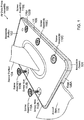
- FIG. 1 is a perspective view of an example air data probe assembly 100.
- the air data probe may be a pitot tube that measures the pressure and/or velocity of air (or fluid) flowing into the sensor portion 104.
- an aircraft may use one or more air data probes to measure airspeed.
- the air data probe assembly 100 may include an air data probe with a baseplate portion 102 and a sensor portion 104.
- the baseplate portion 102 may be generally planar, and the sensor portion 104 may extend (i.e., protrude) from the baseplate portion 102.
- the baseplate portion 102 may have any suitable shape (e.g., triangular, oval, circular, etc.) and corner configuration (e.g., square or rounded).
- the edges of the baseplate portion 102 may be beveled and/or 90 degree angles.
- the air data probe may be made of one or more metals, e.g., titanium, nickel, aluminum, steel, or any other suitable material.
- the air data probe assembly 100 may also include a flexible baseplate gasket 101 with edges 106A-B and a gasket base (not shown).
- the baseplate gasket 101 is illustrated with shading in Figure 1 .
- the baseplate gasket 101 may wrap around the edges and the underside of the baseplate portion 102.
- the term "underside” with reference to an air data probe or baseplate portion 102 may refer to the surface of the air data probe or baseplate portion 102 that is covered or mostly covered by the baseplate gasket 101, i.e., the side that faces the aircraft when installed.
- the term "exterior-side" with reference to an air data probe or baseplate portion 102 may refer to the surface of the air data probe or baseplate portion 102 that is mostly (or completely) uncovered by the baseplate gasket 101, i.e., the side that faces away from the aircraft when installed and/or the side from which the sensor portion 104 protrudes.
- the baseplate gasket 101 may include a lip 108 that extends from one or more of the edges 106 of the baseplate gasket 101 towards the sensor portion 104, i.e., the lip 108 may curl inward and partially overlap the exterior-side of the baseplate portion 102.
- the baseplate gasket 101 may include a lip 108 that extends from one or more of the edges 106 of the baseplate gasket 101 away from the sensor portion 104, i.e., the lip 108 may extend outward (away from the air data probe) to overlap with the adjacent, non-recessed aircraft skin 114.
- the baseplate gasket 101 may include a lip 108 that extends from one or more of the edges 106 of the baseplate gasket 101 towards the sensor portion 104 and away from the sensor portion 104, i.e., the lip 108 may partially overlap the exterior-side of the baseplate portion 102 and extend outward (away from the air data probe) to overlap with the adjacent, non-recessed aircraft skin 114.
- the lip 108 of the baseplate gasket 101 may be level with or rise above the adjacent, non-recessed aircraft skin 114 and/or the exterior-side of the baseplate portion 102.
- the baseplate gasket 101 may not include a lip 108.
- the air data probe assembly 100 may be installed on the aircraft skin 114.
- Aircraft skin 114 is generally an exterior shell covering the aircraft, e.g., made of aluminum and/or other metals.
- a small recess, approximately the same dimensions (i.e., the same footprint) and/or depth as the baseplate portion 102, may be provided in the aircraft skin 114.
- the air data probe assembly 100 may be secured (e.g., fastened) in the recess of the aircraft skin 114 using one or more screw assemblies 110A-110E, e.g., the baseplate gasket 101 may be pressed between the aircraft skin 114 and the air data probe. While only a portion of the aircraft skin 114 is illustrated in Figure 1 , it should be noted that the aircraft skin 114 may surround all four edges 106 when the air data probe assembly is placed in (and secured to) the recess in the aircraft skin 114.
- each screw assembly 110 may include a screw, a flexible screw gasket, a spacer, and/or a cir-clip. Each screw assembly 110 may be screwed into a respective screw hole 112A-B in the baseplate portion 102.
- Each screw gasket may be a moisture-resistant sleeve (e.g., made of silicon, rubber, and/or other materials) that wraps around a portion of a respective screw, e.g., the bottom (and optionally edges) of the screw head.
- the screw gaskets are illustrated with shading in Figure 1 .
- the screw holes 112 in the baseplate portion 102 (and in the aircraft) may be threaded to receive the screw assemblies 110.
- screw herein may refer to any fastener that is drivable and includes a generally cylindrical, threaded portion, e.g., bolt, screw, threaded cylinder, etc.
- the screw assemblies 110 may use any suitable drive type, e.g., Phillips, slotted, hex, Robertson, Torx, Pozidriv, or other proprietary designs.
- any number of screw assemblies 110 may be used to fasten the air data probe assembly 100 to the aircraft. Alternatively, other means of securing the air data probe assembly 100 may be used.
- the baseplate gasket 101 and the screw gasket(s) may form moisture-resistant seals, effectively preventing moisture leaking into the aircraft from the atmosphere, e.g., during flight and on the ground.
- the baseplate gasket 101 may form a seal along the edges 106 and underside of the baseplate portion 102, i.e., preventing moisture from seeping into the aircraft along the edges 106 and underside of the baseplate portion 102.
- the screw gasket(s) (on the screw assembl(ies) 110) may prevent moisture and/or other contamination from seeping in through the screw hole(s) 112.
- the baseplate gasket 101 and the screw gasket(s) may be injection-molded to fit tightly around the baseplate portion 102 and the screws, respectively.
- the baseplate gasket 101 and the screw gasket(s) may be quickly manufactured in a highly-reproducible way without hand-crafting, i.e., no hand layup.
- the air data probe assembly 100 may eliminate downtime required to allow sealant to dry, i.e., cure.
- the baseplate gasket 101 and the screw gasket(s) may be made of silicon, rubber, and/or other moisture-resistant materials to extreme temperatures (hot and cold).
- the air data probe assembly 100 may be attached to the underside of aircraft, any maintenance may be done on a ladder, in the cold, and/or by a technician wearing gloves.
- the air data probe assembly 100 may be mostly preassembled (i.e., during pre-installation, the baseplate gasket 101 may be wrapped around the baseplate portion 102 and the screw gasket(s) may be wrapped around the screws), and require only that screw assemblies 110 be threaded into the aircraft. Pre-assembly may reduce installation time and possible errors, e.g., the technician does not have to guess whether sealant has completely dried.
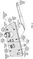
- FIG 2 is a perspective view of the underside of an example air data probe assembly 200.
- the air data probe assembly 200 may include an air data probe (with a baseplate portion 102 and a sensor portion 204) that is partially wrapped by a baseplate gasket 201 with edges 206, a gasket base 216, and optionally a lip (not shown).
- the baseplate gasket 201 is illustrated with shading in Figure 2 .
- one or more screw assemblies 210A-F may be used to fasten the air data probe assembly 200 to the aircraft skin 114.
- the air data probe may include one or more connector 218A-C.
- Each connector 218 maybe a protrusion (e.g., a tube, pipe, duct, hose, connector, pass-through, peg, threaded cylinder, etc.) from the underside of the air data probe.
- Each connector 218 may connect to (or pass through) a hose, tube, braided line, wire, connector and/or cable extending from the aircraft.
- one or more connectors 218 may facilitate electrical, hydraulic, and/or pneumatic (e.g., pressure-sensitive) connection(s) between the aircraft and the air data probe.
- the connectors 218 may use any types of connection, e.g., threaded, threadless gendered, threadless genderless, flanged, quick-connect, etc.
- an electrical line or port on (or extending from) the aircraft may mate to an electrical connector 218 on the underside of the air data probe.
- the electrical line or port on (or extending from) the aircraft may be a male electrical connector, while the electrical connector 218 on the underside of the air data probe may be a female connector.
- the electrical line or port on (or extending from) the aircraft may be a female electrical connector, while the electrical connector 218 on the underside of the air data probe may be a male connector.
- the aircraft may form one or more such electrical connections with the air data probe.
- an electrical connection may provide power and/or heat to a heater in, near, or on the tip of the air data probe 223, i.e., to prevent icing at high altitudes.
- a pneumatic tube or port on (or extending from) the aircraft may mate to a pneumatic connector 218 on the underside of the air data probe.
- the pneumatic tube or port on (or extending from) the aircraft may be a male pneumatic connector, while the pneumatic connector 218 on the underside of the air data probe may be a female connector.
- the pneumatic tube or port on (or extending from) the aircraft may be a female pneumatic connector, while the pneumatic connector 218 on the underside of the air data probe may be a male connector.
- This pneumatic connection may be a low pressure line that enables the air data probe to measure air pressure entering the air data probe.
- the air data probe may include a positioning peg 220 (e.g., a cylindrical protrusion) that extends from the underside of the air data probe.
- the positioning peg 220 may correspond in size and location to a hole in a recess of the aircraft skin 114, i.e., the aircraft may have a hole (the same size as the positioning peg 220) to receive the positioning peg 220.
- the positioning peg 220 may align the air data probe assembly 200 to the correct position on the aircraft skin 200 during installation.
- the air data probe may optionally include a key peg 221 (e.g., a non-cylindrical protrusion) that extends from the underside of the air data probe.
- the key peg 221 may correspond in size, location, and shape to a hole in the recess of the aircraft skin 114, i.e., the aircraft may have a hole (the same size and shape as the key peg 221) to receive the key peg 221. Therefore, the key peg 221 may align the air data probe assembly 200 to the correct position and orientation (e.g., sensor tip 223 pointing to the front of the aircraft) in the recess of the aircraft skin 114 during installation.
- the gasket base 216 may include holes corresponding to the connector(s) 218, screw assembl(ies) 210, optional positioning peg 220, and/or optional key peg 221.
- gasket base 216 may include a separate hole for each connector 218, screw assembly 210, optional positioning peg 220, and optional key peg 221 on the air data probe.
- a single hole in the gasket base 216 may be large enough to allow multiple connector(s) 218, screw assembl(ies) 210, optional positioning peg 220, and/or optional key peg 221 to pass through the gasket base 216.
- some holes in the gasket base 216 may pass a single element (connector 218, screw assembly 210, optional positioning peg 220, and optional key peg 221) through the gasket base 216 while others may pass multiple elements through the gasket base 216.
- the baseplate gasket 216 may cover greater than half the surface area of the underside of the baseplate portion 102, e.g., greater than 50%, 60%, 70%, 80%, or 90%.
- Figures 3A-3E illustrate cross-sectional views of example air data probe assemblies 300A-E, respectively. It should be noted that Figures 3A-3E may not illustrate all components of the air data probe assemblies 300A-E (e.g., connectors 218, screw assemblies 210, positioning peg 220, key peg 221, sensor portion 104 of the air data probe, etc.), but should not be viewed as limiting. Instead, Figures 3A-3E illustrate various examples of lips 308B-E that may extend from the edges 306A-E of the baseplate gaskets 301A-E (or lack thereof).
- Figures 3A-3E illustrate cross-sectional views of example air data probe assemblies 300A-E, respectively. It should be noted that Figures 3A-3E may not illustrate all components of the air data probe assemblies 300A-E (e.g., connectors 218, screw assemblies 210, positioning peg 220, key peg 221, sensor portion 104 of the air data probe, etc.), but should not be viewed as limiting. Instead, Figures 3A
- Figure 3A illustrates a cross-sectional view of an example air data probe assembly 300A that is secured into a recess of the aircraft skin 314A.
- An edge 306A of the baseplate gasket 301A may extend from the gasket base 316A.
- the baseplate gasket 301A may not include a lip 108, i.e., the end of the edge may be level (or approximately level) and non-overlapping with the adjacent, non-recessed aircraft skin 314A and exterior-side of the baseplate portion 302A.
- the baseplate gasket 301A may still form a moisture-resistant seal between the aircraft skin 314A and the baseplate portion 302A because the baseplate portion 302A may be secured (e.g., fastened) tightly to the aircraft skin 314, e.g., using one or more screw assemblies 110.
- the top of the edge 306A may be exposed to the atmosphere following installation of the air data probe assembly 300A.
- Figure 3B illustrates a cross-sectional view of another example air data probe assembly 300B that is secured into a recess of the aircraft skin 314B.
- an edge 306B of the baseplate gasket 301B may extend from the gasket base 316B.
- the baseplate gasket 301B may include a lip 308B that extends beyond the adjacent, non-recessed aircraft skin 314B and the exterior-side of the baseplate portion 302B, e.g., the lip 308B may be exposed to the atmosphere following installation of the air data probe assembly 300B.
- the lip 308B may overlap with the exterior-side of the baseplate portion 302B, which may provide a more comprehensive moisture barrier than the than the configuration in Figure 3A .
- Figure 3C illustrates a cross-sectional view of another example air data probe assembly 300C that is secured into a recess of the aircraft skin 314C.
- the baseplate gasket 301C may include a lip 308C that extends beyond the adjacent, non-recessed aircraft skin 314C and the exterior-side of the baseplate portion 302C, e.g., the lip 308C may be exposed to the atmosphere following installation of the air data probe assembly 300C.
- the lip 308C may overlap with the exterior-side of the baseplate portion 302C and the adjacent, non-recessed aircraft skin 314C, which may provide a more comprehensive moisture barrier than the than the configurations in Figures 3A and 3B .
- Figure 3D illustrates a cross-sectional view of another example air data probe assembly 300D that is secured into a recess of the aircraft skin 314D.
- the baseplate gasket 301D may include a lip 308D that extends beyond the adjacent, non-recessed aircraft skin 314D and the exterior-side of the baseplate portion 302D, e.g., the lip 308D may be exposed to the atmosphere following installation of the air data probe assembly 300D.
- the lip 308D may overlap with only the adjacent, non-recessed aircraft skin 314C, not the exterior-side of the baseplate portion 302D.
- Figure 3E illustrates a cross-sectional view of another example air data probe assembly 300E that is secured into a recess of the aircraft skin 314E.
- the baseplate gasket 301E may include a lip 308E that that does not extend beyond the adjacent, non-recessed aircraft skin 314E. Rather, the edge of the baseplate portion 302E may be beveled, and the lip 308E may overlap a small portion of the exterior-side of the baseplate portion 302E, e.g., the beveled portion of the exterior-side of the baseplate portion 302E. This may provide a more comprehensive moisture barrier and/or greater aerodynamic benefits than Figures 3A-3B .
- the lip 308E may be exposed to the atmosphere following installation of the air data probe assembly 300E.
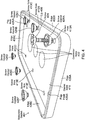
- FIG 4 is a perspective view illustrating an example baseplate gasket 401 and screw gaskets 426A-F.
- the baseplate gasket 401 may be injection-molded and may be made of silicon, rubber, and/or other moisture-resistant materials.
- the baseplate gasket 401 may wrap partially around a baseplate portion 102 of an air data probe.
- the baseplate gasket 401 may form a moisture-resistant seal between the baseplate portion 102 and the aircraft skin 114.
- the baseplate gasket 401 may prevent moisture or other contaminants from seeping in between the baseplate portion 102 and the aircraft skin 114 (and into the aircraft).
- the air data probe assembly 100 may be secured to the aircraft using one or more screw assemblies 110.
- Each screw assembly may include at least a screw gasket 426A-F that is (at least partially) wrapped around a screw 424.
- Each screw assembly 100 may be threaded through a corresponding screw hole 112 in the baseplate portion 102 and a screw hole 413A-F in the gasket base 416.
- the baseplate gasket 401 may include edges 406A-D that extend (generally perpendicular) from the gasket base 416.
- a lip 408 may extend above the edges and curl inward, i.e., toward the center of the baseplate portion 102. Alternatively, or additionally, the lip 408 may curl outward, i.e., extend away from the center of the baseplate portion 102. Alternatively, the lip 408 may curl inward and outward, i.e., toward and away from the center of the baseplate portion.
- the gasket base 416 may include one or more connector holes 422 corresponding to the connectors 218 on the underside of the baseplate portion 102.
- the gasket base 416 may also include one or more screw holes 413A-F corresponding to screw holes 112 in the baseplate portion 102 used to fasten an air data probe assembly 100 to an aircraft.
- the gasket base 416 may also include one or more peg holes 426A-B, e.g., for a positioning peg 220 and/or a key peg 221.
- FIG. 5A is a perspective view of a partially-assembled screw assembly 510A.
- Each screw assembly 510A may include a screw 524A, a flexible screw gasket 526A, a spacer 530, and a cir-clip 532.
- the screw gasket 526A may be a moisture-resistant sleeve (e.g., made of silicon, rubber, and/or other materials) that wraps around a portion of a respective screw 524A, e.g., the bottom (and optionally edges) of the head of the screw 524A.
- the screw gasket 526A may create a moisture-resistant seal between the screw 524A and the baseplate portion 502 and prevent moisture from seeping into the aircraft via a screw hole 512 in the baseplate portion 502.
- the screw gasket526A is illustrated with shading in Figure 5A .
- the flexible screw gasket 526A may prevent the screw gasket 526A from creating a robust, moisture-resistant seal between the screw 524A and the baseplate portion 502.
- the spacer 530 may prevent the flexible screw gasket 526A from bunching up.
- the cir-clip 532 may hold the spacer 530 and the screw gasket 526A in place along the shaft of the screw 524A. In other words, the cir-clip 532 may hold the screw assembly 510A together for easy installation, i.e., an installer can carry a single screw assembly 510A rather than a separate screw 524A, screw gasket 526A, spacer 530, and/or cir-clip 532.
- Each screw assembly 510A may be screwed into a respective screw hole 512 in the baseplate portion 502 and into a screw hole in the aircraft. It should be noted that the screws 524A may use any suitable drive type, e.g., Phillips, slotted, hex, Robertson, Torx, Pozidriv, or other proprietary designs.
- FIG 5B is a perspective view of an assembled screw assembly 510B. Accordingly, in Figure 5B , a screw gasket 526B is wrapped around a screw 524B, i.e., around the bottom (and optionally edges) of the head of the screw 524B. The screw gasket526B is illustrated with shading in Figure 5B . A spacer and a cir-clip may be screwed and slid onto the threaded portion of the screw 524B, respectively. However, the spacer and the cir-clip may not be visible beneath the screw gasket 526B.
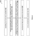
- Figure 6 is a flow diagram illustrating an example method 600 for installing an air data probe assembly 100.
- the method 600 may be performed during aircraft maintenance.
- the method 600 can be implemented using any of the air data probe assemblies or elements described above.
- the method 600 optionally starts at block 602 with assembling one or more screw assemblies 510A.
- Each screw assembly 510A may include a screw 524A that is partially wrapped with a screw gasket 526A.
- the screw gasket 526A may be an injection-molded sleeve (e.g., made of silicon, rubber, and/or other materials) that wraps around a portion of the screw 524A, e.g., the bottom (and optionally edges) of the head of the screw 524A.
- Each screw assembly 510A may also include a spacer 530 that prevents the flexible screw gasket 526A from bunching up.
- Each screw assembly 510A may also include a cir-clip 532 that holds the spacer 530 and the screw gasket 526A in place along the shaft of the screw 524A.
- the cir-clip 532 may hold the screw assembly 510A together 510A as a single assembly rather than requiring an installer to carry a separate screw 524A, screw gasket 526A, spacer 530, and/or cir-clip 532.
- the screw assembly 510A may be preassembled on the ground (and/or off-site) instead of while on a ladder during installation.
- the method 600 proceeds to block 604 with wrapping (e.g., partially wrapping) a baseplate gasket 101 around a baseplate portion 102 of an air data probe to produce an air data probe assembly 100.
- the baseplate gasket 101 may be flexible because it is made of injection-molded silicon, rubber, and/or other moisture-resistant materials. Accordingly, an installer (e.g., a mechanic or technician) may wrap the baseplate gasket 101 around the baseplate portion 102 by hand and without any special tools. Furthermore, the baseplate gasket 101 may be wrapped around the baseplate portion 102 on the ground (and/or off-site) instead of while on a ladder during installation.
- the baseplate portion 102 may include a gasket base 216, edges 106 that extend from the gasket base 216, and optionally, a lip 108 that extends from the edges 106.
- the lip 108 may curl inward and/or outward, i.e., the lip 108 may extend towards a sensor portion 104 of the air data probe and/or away from the sensor portion 104.
- the gasket base 216 may have one or more holes that correspond to one or more elements on the baseplate portion 102.
- the baseplate gasket 101 may have one or more connector holes 422 that correspond in size, location, and/or shape to one or more connectors 218 protruding from the underside of the baseplate portion 102.
- the baseplate gasket 101 may also have one or more peg holes 426 that correspond in size, location, and/or shape to one or more positioning pegs 220 and/or key pegs 221 protruding from the underside of the baseplate portion 102.
- the baseplate gasket 101 may also have one or more screw holes 413 that correspond in size, location, and/or shape to one or more screw holes 112 in the baseplate portion 102.
- the method proceeds to block 606 with coupling one or more electrical components and/or pneumatic components of an aircraft to one or more connectors 218 on an underside of the air data probe.
- an electrical line or port on (or extending from) the aircraft may mate to an electrical connector 218 on the underside of the air data probe, e.g., to provide power and/or heat to a heater in the tip of the air data probe 223 to prevent icing at high altitudes.
- a pneumatic tube or port on (or extending from) the aircraft may mate to a pneumatic connector 218 on the underside of the air data probe, e.g., to form a pneumatic connection that enables the air data probe to measure air pressure entering the air data probe.
- the method proceeds to block 608 with securing the air data probe assembly 100 to the aircraft.
- This may include aligning a positioning peg 220 and/or a key peg 221 on the underside of the air data probe assembly 200 with corresponding holes in the recess of an aircraft skin 114.
- the air data probe assembly 200 may be seated (i.e., placed in) the recess such that the corresponding holes in the recess of an aircraft skin 114 receive the positioning peg 220 and/or the key peg 221 on the underside of the air data probe assembly 200.
- the air data probe assembly 100 may be fastened in a recess of the aircraft skin 114 using one or more screw assemblies 110.
- each screw assembly 110 may be threaded through a screw hole 112 in the baseplate portion 102, a screw hole 413 in the gasket base 416, and into a screw hole in the recess of the aircraft skin 114. Any number of screw assemblies 110 may be used to secure the air data probe assembly 100 to the aircraft.
- the air data probe assembly 100 may be secured to the aircraft without any chemical sealant.
- the baseplate gasket 101 may form a moisture-resistant seal that prevents moisture from entering the aircraft between the aircraft skin 114 and the baseplate portion 102.
- the one or more screw gaskets 526A may form a moisture-resistant seal that prevents moisture from entering the aircraft through the one or more screw holes 512 in the baseplate portion 502. It should be noted that the baseplate gasket 101 and the one or more screw gaskets 526A may provide moisture barriers during flight and on the ground.
- the method 600 may further proceed to block 610 with running electrical and/or pneumatic tests, i.e., to test the electrical and/or pneumatic connections to the air data probe assembly 100.
- the method 600 may be completed in 30 minutes or less.
- phrase “based on” does not mean “based only on,” unless expressly specified otherwise. In other words, the phrase “based on” describes both “based only on” and “based at least on”. Additionally, the term “and/or” means “and” or “or”. For example, “A and/or B” can mean “A”, “B”, or “A and B”. Additionally, “A, B, and/or C” can mean “A alone,” “B alone,” “C alone,” “A and B,” “A and C,” “B and C” or "A, B, and C.”
- connection is not necessarily limited to a direct physical connection or coupling.
- two devices may be coupled directly, or via one or more intermediary media or devices.
- devices may be coupled in such a way that information can be passed there between, while not sharing any physical connection with one another.
- responsive or “in response to” may indicate that an action is performed completely or partially in response to another action.
- the methods disclosed herein comprise one or more steps or actions for achieving the described method.
- the method steps and/or actions may be interchanged with one another without departing from the scope of the claims.
- the order and/or use of specific steps and/or actions may be modified without departing from the scope of the claims.
- the present disclosure provides novel air data probe assembly to facilitate rapid replacement. While detailed descriptions of one or more configurations of the disclosure have been given above, various alternatives, modifications, and equivalents will be apparent to those skilled in the art.
- the scope of this disclosure also includes configurations having different combinations of features, functions, procedures, components, elements, and/or structures, and configurations that do not include all of the described features, functions, procedures, components, elements, and/or structures. Accordingly, the scope of the present disclosure is intended to embrace all such alternatives, modifications, and variations as fall within the scope of the claims, together with all equivalents thereof. Therefore, the above description should not be taken as limiting The invention is defined solely by the appended claims.
Landscapes
- Physics & Mathematics (AREA)
- General Physics & Mathematics (AREA)
- Engineering & Computer Science (AREA)
- Aviation & Aerospace Engineering (AREA)
- General Engineering & Computer Science (AREA)
- Mechanical Engineering (AREA)
- Fluid Mechanics (AREA)
- Connector Housings Or Holding Contact Members (AREA)
- Arrangements For Transmission Of Measured Signals (AREA)
- Measuring Fluid Pressure (AREA)
Claims (10)
- Luftdatensondenanordnung (100), umfassend:eine Luftdatensonde, die einen Grundplattenabschnitt (102) und einen Sensorabschnitt (104) umfasst, wobei der Grundplattenabschnitt (102) ein oder mehrere Schraubenlöcher (112) und einen oder mehrere Verbinder (218) an einer Unterseite des Grundplattenabschnitts (102) umfasst;eine Grundplattendichtung (101), die um die Unterseite und eine oder mehrere Kanten des Grundplattenabschnitts (102) gewickelt ist, wobei die Grundplattendichtung (101) ein oder mehrere Löcher umfasst, die dem einen oder den mehreren Schraubenlöchern (112) und dem einen oder den mehreren Verbindern (218) an der Unterseite des Grundplattenabschnitts (102) entsprechen,wobei der Grundplattenabschnitt (102) konfiguriert ist, an einer Aussparung in einer Flugzeugaußenhaut (114) befestigt zu werden, und die Grundplattendichtung (101) konfiguriert ist, eine feuchtigkeitsbeständige Abdichtung zwischen der Luftdatensonde und der Aussparung in der Flugzeugaußenhaut (114) zu erzeugen, wenn der Grundplattenabschnitt (102) an der Aussparung in der Flugzeugaußenhaut (114) befestigt ist.
- Luftdatensondenanordnung (100) nach Anspruch 1, ferner umfassend eine oder mehrere Schraubenanordnungen (510), die jeweils eine Schraube (524) umfassen, die teilweise von einer Schraubendichtung (526) umwickelt ist, wobei jede Schraubenanordnung (510) durch eines der Schraubenlöcher (112) im Grundplattenabschnitt (102), durch eines der Löcher in der Grundplattendichtung (101) und in ein Loch in einer Aussparung einer Flugzeugaußenhaut (114) gewindet wird.
- Luftdatensondenanordnung (100) nach Anspruch 2, wobei jede Schraubenanordnung (510) ferner einen Abstandshalter (530) umfasst, der verhindert, dass sich die jeweilige Schraubendichtung (526) zusammenballt, und einen Sicherungsring (532), der den Abstandshalter (530) und die jeweilige Schraubendichtung (526) entlang eines Schafts der jeweiligen Schraube (524) hält.
- Luftdatensondenanordnung (100) nach Anspruch 1, wobei die Grundplattendichtung (101) ohne chemisches Dichtungsmittel um die Unterseite und die Kanten des Grundplattenabschnitts (102) gewickelt ist.
- Luftdatensondenanordnung (100) nach Anspruch 1, wobei eine Lippe (108) der Grundplattendichtung (101) teilweise um eine Außenseite des Grundplattenabschnitts (102) gewickelt ist, sodass die Lippe (108) im installierten Zustand der Atmosphäre ausgesetzt ist.
- Verfahren zum Bereitstellen einer Luftdatensondenanordnung (100), wobei das Verfahren umfasst:Wickeln einer Grundplattendichtung (101) um eine Unterseite und eine oder mehrere Kanten eines Grundplattenabschnitts (102) einer Luftdatensonde, um die Luftdatensondenanordnung (100) herzustellen;Anschließen einer oder mehrerer elektrischer Komponenten und/oder pneumatischer Komponenten eines Flugzeugs an einen oder mehrere Verbinder (218) an der Unterseite der Luftdatensonde;
undBefestigen der Luftdatensondenanordnung (100) am Flugzeug, wobei die Grundplattendichtung (101) während des Fluges eine feuchtigkeitsbeständige Abdichtung zwischen der Luftdatensonde und einer Aussparung in der Flugzeugaußenhaut (114) erzeugt. - Verfahren nach Anspruch 6, ferner umfassend das Zusammenbauen einer oder mehrerer Schraubenanordnungen (510), die jeweils eine Schraube (524) umfassen, die teilweise von einer Schraubendichtung (526) umwickelt ist, wobei jede Schraubenanordnung (510) durch eines der Schraubenlöcher (112) im Grundplattenabschnitt (102), durch eines der Löcher in der Grundplattendichtung (101) und in ein Loch in einer Aussparung einer Flugzeugaußenhaut (114) gewindet wird.
- Verfahren nach Anspruch 7, wobei jede Schraubenanordnung (510) ferner einen Abstandshalter (530) umfasst, der verhindert, dass sich die jeweilige Schraubendichtung (526) zusammenballt, und einen Sicherungsring (532), der den Abstandshalter (530) und die jeweilige Schraubendichtung (526) entlang eines Schafts der jeweiligen Schraube (524) hält.
- Verfahren nach Anspruch 6, wobei das Umwickeln das Umwickeln der Grundplattendichtung (101) um eine Unterseite und Kanten des Grundplattenabschnitts (102) ohne chemisches Dichtungsmittel umfasst.
- Verfahren nach Anspruch 6, wobei eine Lippe (108) der Grundplattendichtung teilweise (101) um eine Außenseite des Grundplattenabschnitts (102) gewickelt ist, sodass die Lippe (108) im installierten Zustand der Atmosphäre ausgesetzt ist.
Applications Claiming Priority (1)
| Application Number | Priority Date | Filing Date | Title |
|---|---|---|---|
| US15/978,875 US20190346477A1 (en) | 2018-05-14 | 2018-05-14 | Air data probe assembly to facilitate rapid replacement |
Publications (2)
| Publication Number | Publication Date |
|---|---|
| EP3570044A1 EP3570044A1 (de) | 2019-11-20 |
| EP3570044B1 true EP3570044B1 (de) | 2021-03-03 |
Family
ID=66624981
Family Applications (1)
| Application Number | Title | Priority Date | Filing Date |
|---|---|---|---|
| EP19173962.2A Active EP3570044B1 (de) | 2018-05-14 | 2019-05-10 | Luftdatensondenanordnung zur ermöglichung eines schnellen austausches |
Country Status (3)
| Country | Link |
|---|---|
| US (1) | US20190346477A1 (de) |
| EP (1) | EP3570044B1 (de) |
| CN (1) | CN110487476A (de) |
Family Cites Families (10)
| Publication number | Priority date | Publication date | Assignee | Title |
|---|---|---|---|---|
| US3487463A (en) * | 1968-03-25 | 1969-12-30 | William C Rogers | Marker beacon antenna |
| US4875818A (en) * | 1983-11-30 | 1989-10-24 | Elco Industries, Inc. | Screw having a sealing washer |
| FR2863672B1 (fr) * | 2003-12-16 | 2006-02-03 | Snecma Moteurs | Tole, comportant des moyens de fixation a un support et un joint d'etancheite |
| FR2968278B1 (fr) * | 2010-12-06 | 2012-12-21 | Airbus Operations Sas | Dispositif de protection d'une sonde externe d'un aeronef |
| US9701388B2 (en) * | 2011-05-11 | 2017-07-11 | Aviation Devices & Electronic Components, Llc | Gasket having a pliable resilient body with a perimeter having characteristics different than the body |
| US8857255B2 (en) * | 2012-08-22 | 2014-10-14 | Rosemount Aerospace Inc. | Moisture resistant air data probes |
| US9636763B2 (en) * | 2012-12-31 | 2017-05-02 | Robert Bosch Tool Corporation | Tool-free blade change system |
| US9190116B2 (en) * | 2013-07-08 | 2015-11-17 | Seagate Technology Llc | Hard disc drive cover seal |
| US9859699B2 (en) * | 2015-03-11 | 2018-01-02 | The Patent Well, Llc | Conductive gasket assembly for a corrugated roof of a train car |
| US9909905B2 (en) * | 2015-10-15 | 2018-03-06 | Honeywell International Inc. | Multi-part air data probe assembly to facilitate rapid replacement |
-
2018
- 2018-05-14 US US15/978,875 patent/US20190346477A1/en not_active Abandoned
-
2019
- 2019-05-08 CN CN201910379259.4A patent/CN110487476A/zh not_active Withdrawn
- 2019-05-10 EP EP19173962.2A patent/EP3570044B1/de active Active
Non-Patent Citations (1)
| Title |
|---|
| None * |
Also Published As
| Publication number | Publication date |
|---|---|
| EP3570044A1 (de) | 2019-11-20 |
| US20190346477A1 (en) | 2019-11-14 |
| CN110487476A (zh) | 2019-11-22 |
Similar Documents
| Publication | Publication Date | Title |
|---|---|---|
| EP3156803B1 (de) | Mehrteilige luftdatensonde zur erleichterung eines raschen austauschs | |
| CN110815116B (zh) | 一种阀门预偏装配工装及阀门装配方法 | |
| EP3570044A1 (de) | Luftdatensondenanordnung zur ermöglichung eines schnellen austausches | |
| CN108709728B (zh) | 离心通风器性能试验装置 | |
| CN109115538B (zh) | 一种不可进入式碘吸附器取样装置 | |
| CN107063589B (zh) | 一种真空管道密封检测装置 | |
| CN219777000U (zh) | 一种飞轮壳全型腔气密检测工装 | |
| GB2491799A (en) | Locking of threaded fasteners | |
| CN220470744U (zh) | 一种丝扣密封阀门 | |
| CN120333720A (zh) | 动密封的密封性能测试装置以及测试系统 | |
| CN217424657U (zh) | 气密检测治具及气密检测系统 | |
| CN104819331A (zh) | 用于空调阀门的密封套、空调阀门组件及空调器 | |
| CN219282524U (zh) | 一种便于更换安装的阀组 | |
| CN109707850B (zh) | 一种在压力下传感器在线隔离导通装置及其控制方法 | |
| CN205744792U (zh) | 一种连接器中心螺杆结构 | |
| CN222964699U (zh) | 一种nb远传膜式燃气表用压力传感器 | |
| CN210243489U (zh) | 防爆高光谱远红外气云摄像装置 | |
| CN209762264U (zh) | 一种密封风阀 | |
| CN114563092A (zh) | 一种内嵌型的测温传感结构及测温方法 | |
| CN223991997U (zh) | 一种气动旋转密封阀 | |
| CN113028192A (zh) | 一种用于变压器油色谱回油管路的集气装置 | |
| CN217056297U (zh) | 一种密闭设备的密封装置 | |
| CN206278457U (zh) | 一种连接管堵头及空调器 | |
| CN206022756U (zh) | 电缆接头组件和汽轮机轴瓦温度检测装置的连接结构 | |
| CN223806761U (zh) | 一种汽车空调管路总成 |
Legal Events
| Date | Code | Title | Description |
|---|---|---|---|
| PUAI | Public reference made under article 153(3) epc to a published international application that has entered the european phase |
Free format text: ORIGINAL CODE: 0009012 |
|
| STAA | Information on the status of an ep patent application or granted ep patent |
Free format text: STATUS: THE APPLICATION HAS BEEN PUBLISHED |
|
| AK | Designated contracting states |
Kind code of ref document: A1 Designated state(s): AL AT BE BG CH CY CZ DE DK EE ES FI FR GB GR HR HU IE IS IT LI LT LU LV MC MK MT NL NO PL PT RO RS SE SI SK SM TR |
|
| AX | Request for extension of the european patent |
Extension state: BA ME |
|
| STAA | Information on the status of an ep patent application or granted ep patent |
Free format text: STATUS: REQUEST FOR EXAMINATION WAS MADE |
|
| 17P | Request for examination filed |
Effective date: 20191203 |
|
| RBV | Designated contracting states (corrected) |
Designated state(s): AL AT BE BG CH CY CZ DE DK EE ES FI FR GB GR HR HU IE IS IT LI LT LU LV MC MK MT NL NO PL PT RO RS SE SI SK SM TR |
|
| GRAP | Despatch of communication of intention to grant a patent |
Free format text: ORIGINAL CODE: EPIDOSNIGR1 |
|
| STAA | Information on the status of an ep patent application or granted ep patent |
Free format text: STATUS: GRANT OF PATENT IS INTENDED |
|
| INTG | Intention to grant announced |
Effective date: 20201104 |
|
| GRAS | Grant fee paid |
Free format text: ORIGINAL CODE: EPIDOSNIGR3 |
|
| GRAA | (expected) grant |
Free format text: ORIGINAL CODE: 0009210 |
|
| STAA | Information on the status of an ep patent application or granted ep patent |
Free format text: STATUS: THE PATENT HAS BEEN GRANTED |
|
| AK | Designated contracting states |
Kind code of ref document: B1 Designated state(s): AL AT BE BG CH CY CZ DE DK EE ES FI FR GB GR HR HU IE IS IT LI LT LU LV MC MK MT NL NO PL PT RO RS SE SI SK SM TR |
|
| REG | Reference to a national code |
Ref country code: GB Ref legal event code: FG4D |
|
| REG | Reference to a national code |
Ref country code: CH Ref legal event code: EP Ref country code: AT Ref legal event code: REF Ref document number: 1367778 Country of ref document: AT Kind code of ref document: T Effective date: 20210315 |
|
| REG | Reference to a national code |
Ref country code: DE Ref legal event code: R096 Ref document number: 602019002879 Country of ref document: DE |
|
| REG | Reference to a national code |
Ref country code: IE Ref legal event code: FG4D |
|
| REG | Reference to a national code |
Ref country code: LT Ref legal event code: MG9D |
|
| PG25 | Lapsed in a contracting state [announced via postgrant information from national office to epo] |
Ref country code: NO Free format text: LAPSE BECAUSE OF FAILURE TO SUBMIT A TRANSLATION OF THE DESCRIPTION OR TO PAY THE FEE WITHIN THE PRESCRIBED TIME-LIMIT Effective date: 20210603 Ref country code: LT Free format text: LAPSE BECAUSE OF FAILURE TO SUBMIT A TRANSLATION OF THE DESCRIPTION OR TO PAY THE FEE WITHIN THE PRESCRIBED TIME-LIMIT Effective date: 20210303 Ref country code: BG Free format text: LAPSE BECAUSE OF FAILURE TO SUBMIT A TRANSLATION OF THE DESCRIPTION OR TO PAY THE FEE WITHIN THE PRESCRIBED TIME-LIMIT Effective date: 20210603 Ref country code: GR Free format text: LAPSE BECAUSE OF FAILURE TO SUBMIT A TRANSLATION OF THE DESCRIPTION OR TO PAY THE FEE WITHIN THE PRESCRIBED TIME-LIMIT Effective date: 20210604 Ref country code: FI Free format text: LAPSE BECAUSE OF FAILURE TO SUBMIT A TRANSLATION OF THE DESCRIPTION OR TO PAY THE FEE WITHIN THE PRESCRIBED TIME-LIMIT Effective date: 20210303 Ref country code: HR Free format text: LAPSE BECAUSE OF FAILURE TO SUBMIT A TRANSLATION OF THE DESCRIPTION OR TO PAY THE FEE WITHIN THE PRESCRIBED TIME-LIMIT Effective date: 20210303 |
|
| PGFP | Annual fee paid to national office [announced via postgrant information from national office to epo] |
Ref country code: FR Payment date: 20210526 Year of fee payment: 3 |
|
| REG | Reference to a national code |
Ref country code: NL Ref legal event code: MP Effective date: 20210303 |
|
| REG | Reference to a national code |
Ref country code: AT Ref legal event code: MK05 Ref document number: 1367778 Country of ref document: AT Kind code of ref document: T Effective date: 20210303 |
|
| PG25 | Lapsed in a contracting state [announced via postgrant information from national office to epo] |
Ref country code: SE Free format text: LAPSE BECAUSE OF FAILURE TO SUBMIT A TRANSLATION OF THE DESCRIPTION OR TO PAY THE FEE WITHIN THE PRESCRIBED TIME-LIMIT Effective date: 20210303 Ref country code: RS Free format text: LAPSE BECAUSE OF FAILURE TO SUBMIT A TRANSLATION OF THE DESCRIPTION OR TO PAY THE FEE WITHIN THE PRESCRIBED TIME-LIMIT Effective date: 20210303 Ref country code: PL Free format text: LAPSE BECAUSE OF FAILURE TO SUBMIT A TRANSLATION OF THE DESCRIPTION OR TO PAY THE FEE WITHIN THE PRESCRIBED TIME-LIMIT Effective date: 20210303 Ref country code: LV Free format text: LAPSE BECAUSE OF FAILURE TO SUBMIT A TRANSLATION OF THE DESCRIPTION OR TO PAY THE FEE WITHIN THE PRESCRIBED TIME-LIMIT Effective date: 20210303 |
|
| PG25 | Lapsed in a contracting state [announced via postgrant information from national office to epo] |
Ref country code: NL Free format text: LAPSE BECAUSE OF FAILURE TO SUBMIT A TRANSLATION OF THE DESCRIPTION OR TO PAY THE FEE WITHIN THE PRESCRIBED TIME-LIMIT Effective date: 20210303 |
|
| PG25 | Lapsed in a contracting state [announced via postgrant information from national office to epo] |
Ref country code: SM Free format text: LAPSE BECAUSE OF FAILURE TO SUBMIT A TRANSLATION OF THE DESCRIPTION OR TO PAY THE FEE WITHIN THE PRESCRIBED TIME-LIMIT Effective date: 20210303 Ref country code: AT Free format text: LAPSE BECAUSE OF FAILURE TO SUBMIT A TRANSLATION OF THE DESCRIPTION OR TO PAY THE FEE WITHIN THE PRESCRIBED TIME-LIMIT Effective date: 20210303 Ref country code: EE Free format text: LAPSE BECAUSE OF FAILURE TO SUBMIT A TRANSLATION OF THE DESCRIPTION OR TO PAY THE FEE WITHIN THE PRESCRIBED TIME-LIMIT Effective date: 20210303 Ref country code: CZ Free format text: LAPSE BECAUSE OF FAILURE TO SUBMIT A TRANSLATION OF THE DESCRIPTION OR TO PAY THE FEE WITHIN THE PRESCRIBED TIME-LIMIT Effective date: 20210303 |
|
| PG25 | Lapsed in a contracting state [announced via postgrant information from national office to epo] |
Ref country code: IS Free format text: LAPSE BECAUSE OF FAILURE TO SUBMIT A TRANSLATION OF THE DESCRIPTION OR TO PAY THE FEE WITHIN THE PRESCRIBED TIME-LIMIT Effective date: 20210703 Ref country code: PT Free format text: LAPSE BECAUSE OF FAILURE TO SUBMIT A TRANSLATION OF THE DESCRIPTION OR TO PAY THE FEE WITHIN THE PRESCRIBED TIME-LIMIT Effective date: 20210705 Ref country code: RO Free format text: LAPSE BECAUSE OF FAILURE TO SUBMIT A TRANSLATION OF THE DESCRIPTION OR TO PAY THE FEE WITHIN THE PRESCRIBED TIME-LIMIT Effective date: 20210303 Ref country code: SK Free format text: LAPSE BECAUSE OF FAILURE TO SUBMIT A TRANSLATION OF THE DESCRIPTION OR TO PAY THE FEE WITHIN THE PRESCRIBED TIME-LIMIT Effective date: 20210303 |
|
| REG | Reference to a national code |
Ref country code: DE Ref legal event code: R119 Ref document number: 602019002879 Country of ref document: DE |
|
| PLBE | No opposition filed within time limit |
Free format text: ORIGINAL CODE: 0009261 |
|
| STAA | Information on the status of an ep patent application or granted ep patent |
Free format text: STATUS: NO OPPOSITION FILED WITHIN TIME LIMIT |
|
| PG25 | Lapsed in a contracting state [announced via postgrant information from national office to epo] |
Ref country code: LU Free format text: LAPSE BECAUSE OF NON-PAYMENT OF DUE FEES Effective date: 20210510 Ref country code: DK Free format text: LAPSE BECAUSE OF FAILURE TO SUBMIT A TRANSLATION OF THE DESCRIPTION OR TO PAY THE FEE WITHIN THE PRESCRIBED TIME-LIMIT Effective date: 20210303 Ref country code: AL Free format text: LAPSE BECAUSE OF FAILURE TO SUBMIT A TRANSLATION OF THE DESCRIPTION OR TO PAY THE FEE WITHIN THE PRESCRIBED TIME-LIMIT Effective date: 20210303 Ref country code: MC Free format text: LAPSE BECAUSE OF FAILURE TO SUBMIT A TRANSLATION OF THE DESCRIPTION OR TO PAY THE FEE WITHIN THE PRESCRIBED TIME-LIMIT Effective date: 20210303 Ref country code: ES Free format text: LAPSE BECAUSE OF FAILURE TO SUBMIT A TRANSLATION OF THE DESCRIPTION OR TO PAY THE FEE WITHIN THE PRESCRIBED TIME-LIMIT Effective date: 20210303 |
|
| 26N | No opposition filed |
Effective date: 20211206 |
|
| REG | Reference to a national code |
Ref country code: BE Ref legal event code: MM Effective date: 20210531 |
|
| PG25 | Lapsed in a contracting state [announced via postgrant information from national office to epo] |
Ref country code: SI Free format text: LAPSE BECAUSE OF FAILURE TO SUBMIT A TRANSLATION OF THE DESCRIPTION OR TO PAY THE FEE WITHIN THE PRESCRIBED TIME-LIMIT Effective date: 20210303 |
|
| PG25 | Lapsed in a contracting state [announced via postgrant information from national office to epo] |
Ref country code: IT Free format text: LAPSE BECAUSE OF FAILURE TO SUBMIT A TRANSLATION OF THE DESCRIPTION OR TO PAY THE FEE WITHIN THE PRESCRIBED TIME-LIMIT Effective date: 20210303 Ref country code: IE Free format text: LAPSE BECAUSE OF NON-PAYMENT OF DUE FEES Effective date: 20210510 Ref country code: DE Free format text: LAPSE BECAUSE OF NON-PAYMENT OF DUE FEES Effective date: 20211201 |
|
| PG25 | Lapsed in a contracting state [announced via postgrant information from national office to epo] |
Ref country code: IS Free format text: LAPSE BECAUSE OF FAILURE TO SUBMIT A TRANSLATION OF THE DESCRIPTION OR TO PAY THE FEE WITHIN THE PRESCRIBED TIME-LIMIT Effective date: 20210703 |
|
| PG25 | Lapsed in a contracting state [announced via postgrant information from national office to epo] |
Ref country code: BE Free format text: LAPSE BECAUSE OF NON-PAYMENT OF DUE FEES Effective date: 20210531 |
|
| REG | Reference to a national code |
Ref country code: CH Ref legal event code: PL |
|
| PG25 | Lapsed in a contracting state [announced via postgrant information from national office to epo] |
Ref country code: LI Free format text: LAPSE BECAUSE OF NON-PAYMENT OF DUE FEES Effective date: 20220531 Ref country code: CH Free format text: LAPSE BECAUSE OF NON-PAYMENT OF DUE FEES Effective date: 20220531 |
|
| PG25 | Lapsed in a contracting state [announced via postgrant information from national office to epo] |
Ref country code: FR Free format text: LAPSE BECAUSE OF NON-PAYMENT OF DUE FEES Effective date: 20220531 |
|
| PG25 | Lapsed in a contracting state [announced via postgrant information from national office to epo] |
Ref country code: CY Free format text: LAPSE BECAUSE OF FAILURE TO SUBMIT A TRANSLATION OF THE DESCRIPTION OR TO PAY THE FEE WITHIN THE PRESCRIBED TIME-LIMIT Effective date: 20210303 |
|
| P01 | Opt-out of the competence of the unified patent court (upc) registered |
Effective date: 20230525 |
|
| PG25 | Lapsed in a contracting state [announced via postgrant information from national office to epo] |
Ref country code: HU Free format text: LAPSE BECAUSE OF FAILURE TO SUBMIT A TRANSLATION OF THE DESCRIPTION OR TO PAY THE FEE WITHIN THE PRESCRIBED TIME-LIMIT; INVALID AB INITIO Effective date: 20190510 |
|
| PG25 | Lapsed in a contracting state [announced via postgrant information from national office to epo] |
Ref country code: MK Free format text: LAPSE BECAUSE OF FAILURE TO SUBMIT A TRANSLATION OF THE DESCRIPTION OR TO PAY THE FEE WITHIN THE PRESCRIBED TIME-LIMIT Effective date: 20210303 |
|
| PG25 | Lapsed in a contracting state [announced via postgrant information from national office to epo] |
Ref country code: MT Free format text: LAPSE BECAUSE OF FAILURE TO SUBMIT A TRANSLATION OF THE DESCRIPTION OR TO PAY THE FEE WITHIN THE PRESCRIBED TIME-LIMIT Effective date: 20210303 |
|
| PG25 | Lapsed in a contracting state [announced via postgrant information from national office to epo] |
Ref country code: TR Free format text: LAPSE BECAUSE OF FAILURE TO SUBMIT A TRANSLATION OF THE DESCRIPTION OR TO PAY THE FEE WITHIN THE PRESCRIBED TIME-LIMIT Effective date: 20210303 |
|
| PGFP | Annual fee paid to national office [announced via postgrant information from national office to epo] |
Ref country code: GB Payment date: 20260313 Year of fee payment: 8 |