EP3569979A1 - Piezoelectric ring gyroscope - Google Patents
Piezoelectric ring gyroscope Download PDFInfo
- Publication number
- EP3569979A1 EP3569979A1 EP19172224.8A EP19172224A EP3569979A1 EP 3569979 A1 EP3569979 A1 EP 3569979A1 EP 19172224 A EP19172224 A EP 19172224A EP 3569979 A1 EP3569979 A1 EP 3569979A1
- Authority
- EP
- European Patent Office
- Prior art keywords
- ring
- suspension attachment
- point
- symmetry axis
- oscillation
- Prior art date
- Legal status (The legal status is an assumption and is not a legal conclusion. Google has not performed a legal analysis and makes no representation as to the accuracy of the status listed.)
- Granted
Links
- 230000010355 oscillation Effects 0.000 claims abstract description 96
- 239000000725 suspension Substances 0.000 claims abstract description 86
- 239000000758 substrate Substances 0.000 claims description 4
- 230000033001 locomotion Effects 0.000 description 46
- 230000010360 secondary oscillation Effects 0.000 description 26
- 230000035882 stress Effects 0.000 description 10
- 230000008878 coupling Effects 0.000 description 8
- 238000010168 coupling process Methods 0.000 description 8
- 238000005859 coupling reaction Methods 0.000 description 8
- 238000000034 method Methods 0.000 description 7
- XUIMIQQOPSSXEZ-UHFFFAOYSA-N Silicon Chemical compound [Si] XUIMIQQOPSSXEZ-UHFFFAOYSA-N 0.000 description 5
- 238000005452 bending Methods 0.000 description 5
- 239000004020 conductor Substances 0.000 description 4
- 238000013461 design Methods 0.000 description 4
- 230000005284 excitation Effects 0.000 description 4
- 238000004519 manufacturing process Methods 0.000 description 4
- 238000001514 detection method Methods 0.000 description 3
- 239000003990 capacitor Substances 0.000 description 2
- 230000003247 decreasing effect Effects 0.000 description 2
- 230000000694 effects Effects 0.000 description 2
- 230000005484 gravity Effects 0.000 description 2
- 229910021421 monocrystalline silicon Inorganic materials 0.000 description 2
- 230000026683 transduction Effects 0.000 description 2
- 238000010361 transduction Methods 0.000 description 2
- PIGFYZPCRLYGLF-UHFFFAOYSA-N Aluminum nitride Chemical compound [Al]#N PIGFYZPCRLYGLF-UHFFFAOYSA-N 0.000 description 1
- 230000032683 aging Effects 0.000 description 1
- 230000003679 aging effect Effects 0.000 description 1
- 230000009286 beneficial effect Effects 0.000 description 1
- 239000003086 colorant Substances 0.000 description 1
- 238000010276 construction Methods 0.000 description 1
- 230000008602 contraction Effects 0.000 description 1
- 238000013016 damping Methods 0.000 description 1
- 230000001419 dependent effect Effects 0.000 description 1
- 230000005489 elastic deformation Effects 0.000 description 1
- 230000007613 environmental effect Effects 0.000 description 1
- 230000014509 gene expression Effects 0.000 description 1
- 239000000463 material Substances 0.000 description 1
- 238000005259 measurement Methods 0.000 description 1
- 238000012544 monitoring process Methods 0.000 description 1
- 238000004806 packaging method and process Methods 0.000 description 1
- 229910052710 silicon Inorganic materials 0.000 description 1
- 239000010703 silicon Substances 0.000 description 1
- 239000002210 silicon-based material Substances 0.000 description 1
- 239000007787 solid Substances 0.000 description 1
- 238000013519 translation Methods 0.000 description 1
Images


Classifications
-
- G—PHYSICS
- G01—MEASURING; TESTING
- G01C—MEASURING DISTANCES, LEVELS OR BEARINGS; SURVEYING; NAVIGATION; GYROSCOPIC INSTRUMENTS; PHOTOGRAMMETRY OR VIDEOGRAMMETRY
- G01C19/00—Gyroscopes; Turn-sensitive devices using vibrating masses; Turn-sensitive devices without moving masses; Measuring angular rate using gyroscopic effects
- G01C19/56—Turn-sensitive devices using vibrating masses, e.g. vibratory angular rate sensors based on Coriolis forces
- G01C19/567—Turn-sensitive devices using vibrating masses, e.g. vibratory angular rate sensors based on Coriolis forces using the phase shift of a vibration node or antinode
- G01C19/5677—Turn-sensitive devices using vibrating masses, e.g. vibratory angular rate sensors based on Coriolis forces using the phase shift of a vibration node or antinode of essentially two-dimensional vibrators, e.g. ring-shaped vibrators
- G01C19/5684—Turn-sensitive devices using vibrating masses, e.g. vibratory angular rate sensors based on Coriolis forces using the phase shift of a vibration node or antinode of essentially two-dimensional vibrators, e.g. ring-shaped vibrators the devices involving a micromechanical structure
-
- G—PHYSICS
- G01—MEASURING; TESTING
- G01C—MEASURING DISTANCES, LEVELS OR BEARINGS; SURVEYING; NAVIGATION; GYROSCOPIC INSTRUMENTS; PHOTOGRAMMETRY OR VIDEOGRAMMETRY
- G01C19/00—Gyroscopes; Turn-sensitive devices using vibrating masses; Turn-sensitive devices without moving masses; Measuring angular rate using gyroscopic effects
- G01C19/56—Turn-sensitive devices using vibrating masses, e.g. vibratory angular rate sensors based on Coriolis forces
- G01C19/5705—Turn-sensitive devices using vibrating masses, e.g. vibratory angular rate sensors based on Coriolis forces using masses driven in reciprocating rotary motion about an axis
- G01C19/5712—Turn-sensitive devices using vibrating masses, e.g. vibratory angular rate sensors based on Coriolis forces using masses driven in reciprocating rotary motion about an axis the devices involving a micromechanical structure
-
- H—ELECTRICITY
- H03—ELECTRONIC CIRCUITRY
- H03H—IMPEDANCE NETWORKS, e.g. RESONANT CIRCUITS; RESONATORS
- H03H9/00—Networks comprising electromechanical or electro-acoustic devices; Electromechanical resonators
- H03H9/02—Details
- H03H9/02244—Details of microelectro-mechanical resonators
- H03H9/02338—Suspension means
- H03H2009/02346—Anchors for ring resonators
-
- H—ELECTRICITY
- H03—ELECTRONIC CIRCUITRY
- H03H—IMPEDANCE NETWORKS, e.g. RESONANT CIRCUITS; RESONATORS
- H03H9/00—Networks comprising electromechanical or electro-acoustic devices; Electromechanical resonators
- H03H9/02—Details
- H03H9/02244—Details of microelectro-mechanical resonators
- H03H9/02259—Driving or detection means
-
- H—ELECTRICITY
- H03—ELECTRONIC CIRCUITRY
- H03H—IMPEDANCE NETWORKS, e.g. RESONANT CIRCUITS; RESONATORS
- H03H9/00—Networks comprising electromechanical or electro-acoustic devices; Electromechanical resonators
- H03H9/24—Constructional features of resonators of material which is not piezoelectric, electrostrictive, or magnetostrictive
- H03H9/2405—Constructional features of resonators of material which is not piezoelectric, electrostrictive, or magnetostrictive of microelectro-mechanical resonators
- H03H9/2431—Ring resonators
Definitions
- the present disclosure relates to sensors for measuring angular rotation rates, and more particularly to z-axis gyroscopes where the oscillation of a ring-shaped structure in a given plane is utilized to detect the magnitude of angular rotation about an axis perpendicular to that plane.
- the present disclosure further concerns transducers which may be used to drive the primary ring oscillation, to measure the magnitude of the primary ring oscillation, to detect the secondary ring oscillation induced by angular rotation, or to drive counter-oscillation in the secondary mode.
- the present disclosure also concerns means for adjusting the resonance properties of the ring with attached mass elements, and means for suspending the ring from a fixed substrate.
- Microelectromechanical gyroscopes use the Coriolis effect to measure angular velocity.
- an object In vibrating MEMS gyroscopes, an object is driven into oscillating movement by an actuating drive force.
- This oscillation will be called “primary oscillation” or “drive oscillation” in this disclosure, and the oscillation mode will be labelled called the “primary mode”. It may also be labelled the "primary resonance mode", since the ring typically vibrates in resonance.
- the drive oscillation can involve linear or rotational oscillation of a solid inertial mass, but it can also involve flexible deformation of a ring-shaped structure. This disclosure focuses exclusively on applications of the latter kind.
- the ring When a ring in drive oscillation undergoes an angular rotation rate ⁇ about the z-axis (perpendicular to the xy-plane defined by the ring), the ring is affected by the Coriolis force Fc.
- the magnitude and direction of the Coriolis force on a given segment of the ring is determined by the magnitude and direction of vibrational motion on that segment of the ring and by the magnitude of the angular rotation rate vector.
- the oscillation caused by the Coriolis force in the ring will be called “secondary oscillation” or “sense oscillation” in this disclosure, and the oscillation mode will be labelled called the “secondary mode” or the “secondary resonance mode”.
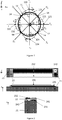
- Figure 1 illustrates the primary and secondary modes in an oscillating ring gyroscope.
- the thick ring 11 illustrates the ring in its rest position, which it obtains when it is entirely at rest or when the amplitudes of all vibration modes are zero.
- Two transversal symmetry axes T 1 and T 2 and two diagonal symmetry axes D 1 and D 2 are illustrated in the ring shown in Figure 1 .
- the primary mode involves ring vibration along the two transversal symmetry axes.
- the two extremes of this vibrational movement have been illustrated with dotted lines in Figure 1 .
- the first dotted line 12 shows the shape of the ring when it has expanded along the first transversal axis T 1 and contracted along the second transversal axis T 2
- the second dotted line 13 shows the shape of the ring when it has expanded along the second transversal axis T 2 and contracted along the first transversal axis T 1 .
- the ring continuously switches between these two shapes.
- segments on the ring are influenced by the Coriolis force F C .
- the forces F C marked on the first dotted line 12 illustrate the local direction of the Coriolis force when the ring is expanding along the first transversal axis T 1 .
- F C points in the negative y-direction in this segment.
- F C points in the positive y-direction in this segment.
- segment 123 moves in the negative y-direction and F C points in the negative x-direction in this segment.
- Segment 124 moves in the positive y-direction and F C points in the positive x-direction in this segment, as illustrated in Figure 1 .
- the forces F C marked on the second dotted line 13 illustrate the local direction of the Coriolis force when the ring is expanding along the second transversal axis T 2 .
- F C points in the positive y-direction.
- F C points in the negative y-direction.
- Segment 133 moves in the positive y-direction and F C points in the positive x-direction, while segment 124 moves in the negative y-direction and F C points in the negative x-direction in this segment.
- the direction of the Coriolis forces are again reversed in each segment when the ring again contracts along the second transversal axis T 2 (this situation is not illustrated).
- the Coriolis force has been drawn only on these segments of the ring in Figure 1 .
- the Coriolis force will act at every point of the ring along its perimeter.
- Each local force component is proportional to the velocity of that point of the ring and to the angular rate, and is perpendicular to both.
- the integral of all the Coriolis force components causes an elliptic deformation of the ring along the first and second diagonal axes D 1 and D 2 .
- the annular ring 11 deforms periodically to elliptic shapes 12 and 13 along the orthogonal transversal axes T 1 and T 2 .
- the segments of the ring which lie at these nodal points 14 do not experience any linear movement in primary oscillation, only rotation around the node point.
- the secondary resonance mode In the secondary resonance mode, the elliptical deformations are turned by 45 degrees from the primary mode axes, as explained above. Mathematically (but not geometrically), the secondary mode is orthogonal to the primary mode, since all possible oscillations of the ring can be expressed as linear combinations of these two modes.
- the superposition of the two oscillations is an elliptic oscillation where the nodal points 14 are slightly shifted from the original locations.
- the angular rotation rate can be detected by measuring this shift.
- Ring gyroscopes where the oscillations of the ring are driven by capacitive or electromagnetic means are known from the prior art. The detection of the secondary oscillation is typically performed by capacitive means. Documents US5932804 and US5226321 exemplify such gyroscopes.
- Capacitive transducers have to be manufactured near the side surfaces of the ring by placing an electrode at a distance from the side surface, so that a voltage applied between the ring and the electrode is able to deform the ring (in the primary mode), or that the deformation of the ring (in the secondary mode) can be measured by the capacitance between the ring and the electrode.
- Electromagnetic excitation of the primary mode requires conductors formed on the top surface of the ring which impart a force to the ring when it is placed in an external magnetic field produced by a permanent magnet.
- the detection capacitances are very small since it is very difficult to manufacture air gaps smaller than 1 ⁇ m, and the high amplitude of the primary oscillation puts limits on how far from the nodal points the secondary mode detection electrodes can be extended.
- the excitation capacitors needed for the primary mode must have a large gap to allow large amplitude oscillation, and thus the electrostatic force generated by these capacitors remains very small. If electromagnetic excitation is used, there is no space for multi-turn conductors on the ring, and a strong and large permanent magnet therefore has to be used. Such devices are typically not compatible with the standard packaging requirements of silicon devices.
- An object of the present disclosure is to provide an apparatus which alleviates the above disadvantages.
- the disclosure is based on the idea of utilizing piezoelectric transducers for exciting the primary resonance mode in the ring gyroscope and for detecting the secondary resonance mode. Furthermore, the disclosure describes how the resonance properties of the device can be changed by fastening additional mass elements to the ring with narrow bridge connectors, and how the ring can be suspended.
- Figure 2 illustrates three cross-sections of a bending piezoelectric transducer placed on a gyroscope ring.
- the transducer can generate or measure bending motion in the xy-plane.
- a pair of first electrode layers 241 and 242 have been placed on silicon ring 21, one on the upper side of a layer of piezoelectric material 22 and one on the lower side (up and down refers in this case to the direction of the z-axis). These electrodes are paired with second electrode layers 231 and 232, respectively, as illustrated in the figure.
- Layers 241, 22 and 231 together form a first piezoelectric transducer on top of the ring 21, and layers 242, 22 and 232 together form a second piezoelectric transducer on top of the ring 21.
- the two transducers If drive voltages with opposite polarity are applied to these two transducers, the two transducers produce opposite strains in the xy-plane, which can deform silicon ring 21. If the transducers are used as sense transducers, in-plane bending will generate a voltage differential between the two transducers.
- Black and white colours indicate transducer polarity.
- the ordering of the black and white rectangles in a split transducer indicate polarity so that the polarity of a transducer with a white rectangle on the outer side of the ring is opposite to the polarity of a transducer with a black rectangle on the black rectangle on the outside of the ring (as seen in the same figure).
- the thickness of the silicon ring 21 may, for example, be between 4 - 100 ⁇ m, preferably between 10 - 50 ⁇ m.
- the largest output voltage between the electrodes of the transducer may be achieved when the transducer capacitance equals the sum of the capacitance of the external connections and the input capacitance of the amplifier.
- the capacitance of the transducer is determined by its area and by the thickness of the piezoelectric layer.
- the primary and secondary oscillation modes produce mechanical stress on the inner and outer perimeter of the ring.
- the momentary stress varies as a sinusoidal function of length along the ring perimeter.
- the length variable is in this case represented by the clockwise angle with respect to the T2-axis pointing in the positive y-direction in Figure 1 .
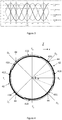
- Figure 3 shows the variation of tangential stress along the inner and outer perimeters of the ring for both oscillation modes.
- the stress varies as a sine-function of the angle for the primary mode and as a cosine-function for the secondary mode, and the stress on the inner perimeter is in each case equal but opposite to the stress on the outer perimeter.
- This stress distribution can be generated and detected by piezoelectric split transducers positioned on the top surface of the ring and lengthwise along the perimeter of the ring.
- a split transducer positioned on the ring for driving the primary oscillation will produce opposite and constant stress on each perimeter of the ring.
- a ring gyroscope which comprises a substantially circular and flexible ring which defines a ring plane, and which is flexibly suspended from a substrate so that the ring can undergo shape oscillation in the ring plane.
- the ring comprises first and second transversal symmetry axes in the ring plane which are orthogonal to each other, and the ring also comprises first and second diagonal symmetry axes in the ring plane which are orthogonal to each other, and the angle between each transversal symmetry axis and the adjacent diagonal symmetry axis is 45°.
- the gyroscope further comprises one or more primary piezoelectric split transducers configured to drive the ring into resonance oscillation, placed on first sectors of the ring, and one or more secondary piezoelectric split transducers configured to sense the oscillation of the ring, placed on one or more second sectors of the ring.
- Each first sector crosses a transversal symmetry axis of the ring and is symmetric with respect to that symmetry axis
- each second sector crosses a diagonal symmetry axis of the ring and is symmetric with respect to that diagonal symmetry axis of the ring.
- the gyroscope also comprises a suspension structure configured to support the weight of the ring and the mass elements, wherein the suspension structure comprises N outer suspenders, where N is an integer greater than or equal to two, and each outer suspender extends along a ring tangent from a suspension attachment point on the outer edge of the ring to an anchor point.
- the suspension attachment points are substantially evenly distributed along the ring perimeter, and the ratio between the vertical thickness of each outer suspender in the direction perpendicular to the ring plane and the radial width of that outer suspender in the direction of the ring radius is at least 4.
- the gyroscope may optionally comprise four or more mass elements which form a symmetrical mass distribution in relation to both the first and second transversal symmetry axes and to the first and second diagonal symmetry axes, wherein each mass element is attached to the ring from a bridge connector and the bridge connectors are evenly distributed along the ring.
- This disclosure also describes a method for using a ring gyroscope described above, wherein the method comprises the steps of: applying to at least one primary piezoelectric split transducer a drive voltage signal to generate the primary oscillation mode in the ring gyroscope, and reading from at least one secondary piezoelectric split transducer a sense voltage signal to measure the oscillation amplitude of secondary oscillation in the ring gyroscope.
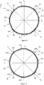
- Figure 4 illustrates a ring gyroscope which comprises a ring 42.
- the planar ring defines the ring-plane which corresponds to the xy-plane in Figure 4 .
- the suspension arrangement is not illustrated.
- the first and second transversal symmetry axes T 1 and T 2 , and the first and second diagonal symmetry axes D 1 and D 2 correspond to the symmetry axes discussed above with reference to Figure 1 .
- At least one primary piezoelectric split transducer 411 has been placed on the ring 42. This split transducer 411 covers a first sector of the ring which corresponds to the angle ⁇ , as illustrated in Figure 4 .
- the midpoint of this sector (or, equivalently, the midpoint of the transducer 411) defines the direction of first transversal symmetry axis T 1 .
- An alternating drive voltage applied to split transducer 411 will alternately stretch and compress the ring 42 along transversal symmetry axis T 1 .
- the direction of the first symmetry axis can be freely selected by the placement of the first primary split transducer 411.
- the other three symmetry axes T 2 , D 1 and D 2 have also already been uniquely defined, and the placement of subsequent primary and secondary split transducers on the ring must conform to the following requirements:
- At least one primary piezoelectric split transducer should be present on the ring to excite the primary resonance motion of the ring. This excitation is achieved by applying an alternating voltage to the primary piezoelectric split transducer, with a frequency which is equal or close to the resonance frequency of the ring.
- the primary piezoelectric split transducers should preferably be placed symmetrically in relation to a transversal symmetry axis of the ring.
- At least one secondary piezoelectric split transducer should be present on the ring to detect the oscillation coupled by the Coriolis force when the ring rotates about its central axis which is perpendicular to the ring plane.
- the secondary piezoelectric split transducers should preferably be placed symmetrically in relation to a diagonal symmetry axis of the ring.
- any first or second sector i.e. any primary or secondary transducer
- any first or second sector i.e. any primary or secondary transducer
- the oscillation of the nodal point 44 will be picked up by secondary split transducers 431 - 434 and create an erroneous sense signal.
- a misaligned secondary transducer will be centered at a point which differs from the nodal point 44, which also leads it to pick up the primary resonance oscillation and to produce an erroneous sense signal. If, on the other hand, all primary and secondary split transducers are perfectly aligned, then secondary split transducers 431 - 434 will only pick up the true secondary resonance mode, which is the oscillation of nodal points 44 induced by the Coriolis force.
- a single primary piezoelectric split transducer on a first sector of the ring and a single secondary split transducer on a second sector of the ring is sufficient for operating the ring gyroscope.
- the number of both primary and secondary split transducers may be increased according to geometry illustrated as illustrated in Figure 4 .
- the gyroscope may comprise a first pair of primary piezoelectric split transducers 411, 412 on two first sectors which cross the first transversal symmetry axis T 1 on opposite sides of the ring 42.
- the gyroscope may also comprise a second pair of primary piezoelectric split transducers 413, 414 on two first sectors which cross the second transversal symmetry axis T 2 on opposite sides of the ring 42.
- the first pair of primary piezoelectric split transducers 411, 412 may have a polarity-symmetry with respect to the center of the ring 42 which is opposite to the polarity-symmetry of the second pair of piezoelectric split transducers 413, 414 with respect to the center of the ring 42.
- the gyroscope may comprise a first pair of secondary piezoelectric split transducers 431, 432 on two second sectors which cross the first diagonal symmetry axis D 1 on opposite sides of the ring 42.
- the gyroscope may also comprise a second pair of secondary piezoelectric split transducers 433, 434 on two second sectors which cross the second diagonal symmetry axis D 2 on opposite sides of the ring 42.
- the first pair of secondary piezoelectric split transducers 431, 432 may have a polarity-symmetry with respect to the center of the ring 42 which is opposite to the polarity-symmetry of the second pair of secondary piezoelectric split transducers 433, 434 with respect to the center of the ring 42.
- each first sector and each second sector is 45°.
- the length of each primary split transducer 411 - 414 and the length of each secondary split transducer 431 - 433 is equal to 1/8 of the ring circumference.
- the primary and secondary split transducers together cover the entire circumference of the ring. This maximizes the force obtained from the primary transducers and the sense signal strength obtained from the secondary transducers.
- Figure 5 illustrates a ring gyroscope according to another transducer embodiment.
- Reference numbers 511 - 514, 531 - 534, 52 and 54 correspond to reference numbers 411 - 414, 431 - 434, 42 and 44, respectively in Figure 4 .
- the width of each first sector is less than 45°
- the width of each second sector is less than 45°.
- the length of each transducer is 1/16 of the ring circumference, so that the corresponding width of each first and second sector is 22.5°, but transducer lengths can be selected freely.
- the symmetry criterion remains the same as in Figure 4 : each first and second sector should be symmetric with respect to the symmetry axis which it crosses. Deviations from this symmetry will cause unwanted coupling of primary mode oscillation into the secondary mode, as described above.
- Figure 6 illustrates an alternative transducer embodiment where the width of all first sectors and two second sectors is less than 45°, and the width of the two other second sectors is 45°.
- Reference numbers 611 - 614, 631 - 634, 62 and 64 correspond to reference numbers 511 - 514, 531 - 534, 52 and 54, respectively, in Figure 5 .
- the width of each first sector may be less than 45°, and the width of each second sector may be 45°.
- the force required for driving the primary oscillation depends on the dimensions of the ring, the length of the primary transducers and the amplitude of the drive voltage signal applied to these primary transducers. As before, each first and second sector must still be symmetric with respect to the symmetry axis which it crosses.
- At least one secondary piezoelectric split transducer may be driven with an alternating voltage so that it actively cancels the coupling of the primary oscillation into the secondary.
- the lengths of the secondary transducers which are dedicated to active cancelling may then differ from the lengths of the secondary transducers which sense the secondary oscillation.
- each first sector may be 45°
- the width of each second sector may be less than 45°.
- This configuration can be advantageous for freeing space on the ring when the driving force must be maximized, but some of the sense signal strength can be sacrificed.
- This option is not separately illustrated, but it corresponds directly to Figure 6 , except that each primary split transducer would cover 1/8 of the ring circumference, while no secondary split transducer would cover that much of the circumference.
- All primary split transducers do not necessarily have to be used for driving the primary oscillation. Some of them may, for example, be used for measuring the amplitude of the primary oscillation. This is needed for maintaining stable oscillation amplitude independent of the changes in the driving frequency or the Q-value of the resonator due to environmental variables or aging.
- a method for using any ring gyroscope described in this disclosure may comprise the step of reading from at least one primary piezoelectric split transducer a third voltage signal to measure the oscillation amplitude of primary oscillation in the ring gyroscope.
- all secondary split transducers do not necessarily have to be used for measuring the secondary oscillation. Some of them may, for example, be used for active interventions into the secondary oscillation mode. For example, when the ring gyroscope is used in closed-loop servo mode, or when the secondary mode resonance is damped by closed loop feedback, or when an applied electromechanical force is used to cancel a quadrature signal, at least one secondary piezoelectric split transducer may be driven with an alternating voltage so that it actively cancels the coupling of the primary oscillation into the secondary oscillation. The lengths of the secondary transducers which are dedicated to active cancelling may differ from the lengths of the secondary transducers which sense the secondary oscillation.
- a method for using any ring gyroscope described in this disclosure may comprise the step of applying to at least one secondary piezoelectric split transducer a fourth voltage signal to actively cancel the coupling of the primary oscillation into the secondary oscillation.
- Figure 7 illustrates an alternative embodiment where reference numbers 711 - 714, 731 - 734, 72 and 74 correspond to reference numbers 611 - 614, 631 - 634, 62 and 64, respectively, in Figure 6 .
- the width of at least one first or second sector is less than 45°.
- the gyroscope comprises one or more tertiary piezoelectric split transducers on third sectors of the ring, which do not overlap with the first sectors or the second sectors.
- tertiary piezoelectric split transducers 751 - 758 are illustrated in Figure 7 .
- the number of tertiary piezoelectric split transducers could be smaller, and it may depend on the widths of the primary and secondary transducers.
- the number of tertiary piezoelectric split transducers may also be larger than eight.
- Several third sectors may fit between first and second sectors.
- One or more of the tertiary piezoelectric transducers 751 - 758 may be used for detecting the amplitude of the primary oscillation. This amplitude may not remain constant during the lifetime of the device due to temperature stress and other aging effects. Drift in the drive amplitude will immediately introduce a proportional error in the sensed amplitude, but this error can be corrected if the primary oscillation is monitored.
- a method for using a ring gyroscope which comprises one or more tertiary piezoelectric split transducers on third sectors of the ring which do not overlap with the first sectors or the second sectors may comprise the step of reading from at least one tertiary piezoelectric split transducer a fifth voltage signal to measure the oscillation amplitude of primary oscillation in the ring gyroscope.
- One or more of the tertiary piezoelectric transducers 751 - 758 may also be used for cancelling coupled oscillation when the gyroscope is used in closed loop servo mode or when the secondary resonance mode is actively damped by closed-loop feedback, or when electromechanical force is used to cancel a quadrature signal, as described above.
- a method for using a ring gyroscope which comprises one or more tertiary piezoelectric split transducers on third sectors of the ring which do not overlap with the first sectors or the second sectors may comprise the step of applying to at least one tertiary piezoelectric split transducer a sixth voltage signal to actively cancel the coupling of the primary oscillation into the secondary oscillation.
- Figure 8 illustrates an alternative embodiment where reference numbers 811 - 814, 831 - 834, 855 - 856, 82 and 84 correspond to reference numbers 711 - 714, 731 - 734, 755 - 756, 72 and 74, respectively, in Figure 7 .
- three of the secondary transducers on the second sectors, 831-833 have a width larger than 45°
- the fourth one, 834 has a width less than 45°. All of these secondary transducers are used for detecting the secondary oscillation.
- All transducers on the primary sectors, 811-814 have a width less than 45°, and they are used for exciting the primary oscillation.
- One of these tertiary transducers is used for detecting the amplitude of the primary oscillation, as described above.
- the other is used for cancelling coupled oscillation when the gyroscope is used in closed loop servo mode or when the secondary resonance mode is actively damped by closed-loop feedback, or when electromechanical force is used to cancel a quadrature signal, as described above.
- the whole perimeter of the ring may be fully covered by transducers for the described functions.
- the gyroscope may be optimized by selecting optimum transducer lengths for each function, so that sufficiently high signal-to-noise ratios for the primary and secondary signals while keeping the voltages for driving the primary oscillation and for compensating the secondary oscillation by applied electromechanical force suitably low.
- piezoelectric transducers are fabricated on the top surface of the ring.
- a practical split electrode transducer requires at least 15 ⁇ m, preferably more than 20 ⁇ m of width.
- a silicon ring with an outer diameter of 1000 ⁇ m and a width 6.8 ⁇ m has a 30 kHz resonant frequency, but it is nearly impossible to manufacture piezoelectric split-transducers on the top surface of such a narrow ring.
- the width of the ring In order to implement piezoelectric transduction on a basic gyroscope ring, the width of the ring must be increased. This increases the resonance frequency. A ring width of 15 ⁇ m increases the resonance frequency to 67 kHz. But even this may be too narrow, because the total maximum capacitance of a 15 ⁇ m wide split transducer with a 1 ⁇ m AIN layer is only 3,8 pF, which will be shared with many functions in addition to sensing the secondary oscillation: e.g. driving the primary oscillation, sensing the magnitude of the primary oscillation and driving a compensating signal in the secondary mode to cancel the secondary oscillation in a closed feed-back loop and/ or damping the secondary resonance and/ or cancelling the quadrature signal.
- the total capacitance should preferably be 7-15 pF since it is not easy to use more than 50% of the maximum capacitance for sensing the secondary oscillation.
- Figure 9a illustrates an exemplary ring gyroscope according to one embodiment. Piezoelectric transducers have been omitted from the figure to preserve clarity, but any of the transducer embodiments described above can be implemented with any of the embodiments described in this disclosure.
- reference number 92 in Figure 9a may correspond to any of the reference numbers 42, 52, 62 or 72 from the preceding figures.
- Figure 9a shows a ring 92 with 32 small mass elements 93, all of which are located inside the ring. Each mass element 93 is shaped like a partial circle sector within the ring, but other shapes may also be used.
- Each mass element 93 is attached to the ring from a bridge connector 94.
- the width of a bridge connector along the ring periphery is substantially less than the width of the corresponding mass element 93 along the ring periphery to ensure that the flexibility of the ring is affected as little as possible by the mass elements which have been added to the ring.
- the bridge connector 94 must nevertheless be sufficiently wide to support the weight of the mass element 93. The minimum width therefore depends on the size of the mass element. In the vertical z-direction perpendicular to the xy-plane the bridge connector 94 may be as high the mass element 93 and the ring 92, because the in-plane flexibility of the ring 92 does not depend on the vertical height of the bridge connector 94.
- the radial length of the bridge connector 94 should be as small as possible, limited by the required clearance between the ring and the mass element to allow large amplitude primary oscillation and by manufacturing tolerances.
- the radial length should be small enough so that any bending of the bridge connector is negligible compared to the elastic deformation of the ring in the primary and secondary oscillation modes.
- the mass distribution produced by the sum of all mass elements 93 must be symmetric in relation to both the first and second transversal symmetry axes T 1 and T 2 and to the first and second diagonal symmetry axes D 1 and D 2 in order to maintain the two elliptical resonance modes of the ring at 45° angle as shown in in Figure 1 and explained above, and not to introduce any other low order in-plane resonance modes. This is needed to maintain the basic benefits of a ring gyroscope: to achieve a high Q-value of the resonance without any oscillation energy leaking out and to achieve good robustness to external linear and angular vibrations.
- the effective moving mass for one oscillation mode is 29.7% of the total ring mass.
- the moving mass is considerably increased without affecting the spring constant of the ring. If the radial length of the mass elements in Figure 9a or 9b is 200 ⁇ m, a ring width of 20 ⁇ m can produce a resonant frequency at 30 kHz. Without the added mass elements 93, the resonant frequency of the 20 ⁇ m wide ring would be 91 kHz.
- the effective moving mass in one oscillation mode becomes 25 times larger than the effective mass in one oscillation mode when only a 6.8 ⁇ m wide ring (suitable for producing a resonance frequency of 30 kHz) is used.
- 25 times the original oscillation energy is stored in the resonating system when these additional mass elements are used, which results in an output signal amplitude which is 5 times greater than the original maximum output signal.
- the total capacitance of the 20 ⁇ m wide set of transducers would be 4.9 pF if 1 ⁇ m AIN is used.
- the desired resonance frequency would be 50 kHz
- a bare ring without mass elements would have to be only 11 ⁇ m of wide to achieve the desired frequency. This is too narrow for a piezoelectric transducer.
- the radial length of the mass elements 93 in Figure 9a and 9b would be 200 ⁇ m
- the presence of the mass elements increases the available width to 28 ⁇ m while still maintaining the resonant frequency at 50 kHz.
- the energy of the oscillation is in this case increased by a factor of 16, and the signal amplitude by a factor of 4, compared to the gyroscope without added mass elements.
- the total transducer capacitance is increased to 6.8 pF. If the radial length of the mass elements 93 is increased to 370 ⁇ m, the ring width can be increased to 31 ⁇ m at 50 kHz resonant frequency. The total capacitance will then be 7.5 pF.
- a suitable radial length of the mass elements may, for example, be in the range 50 - 500 ⁇ m, 100 - 400 ⁇ m, or 200 - 300 ⁇ m.
- the ring width may, for example, be 15 - 50 ⁇ m, 20 - 40 ⁇ m or 25 - 35 ⁇ m. If the ring diameter is larger than 1000 ⁇ m, the radial length of the mass elements and the ring width may be increased in the same proportion.
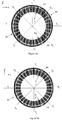
- Figures 10a - 10e illustrate exemplary ring gyroscopes according to an alternative embodiment.
- the size of the mass elements has been increased, and their number decreased.
- Figure 10a illustrates an embodiment where all mass elements 1031 and 1032 are located inside the ring.
- the number of mass elements is eight, and each mass element is placed so that it crosses one symmetry axis, so that it is symmetric in relation to that symmetry axis, and so that its bridge connector is centered on that symmetry axis.
- the ring gyroscope in Figure 10a comprises four mass elements 1031 which cross a transversal symmetry axis, and four mass elements 1032 which cross a diagonal symmetry axis.
- the mass elements 1031 are attached to the ring 102 with bridge connectors 1041 which cross the same transversal symmetry axis as the mass element.
- the mass elements 1032 are attached to the ring 102 with bridge connectors 1042 which cross the same diagonal symmetry axis as the mass element. Due to the greater size of the mass elements 1031 and 1032 compared to mass elements 93, the bridge connectors 1041 and 1042 also have to be wider than bridge connectors 94 in Figures 9a and 9b .
- mass elements 1031 will move back and forth along the transversal symmetry axes T 1 and T 2 in drive oscillation.
- mass elements 1032 When sense oscillation occurs, mass elements 1032 will correspondingly move back and forth along the diagonal symmetry axes D 1 and D 2 .
- the best signal-to-noise ratio is typically obtained when the resonance frequency of the primary mode equals the resonance frequency of the secondary mode. This balance is obtained in the configuration in Figure 10a when each mass element occupies an equally wide partial circle sector.
- the width of each partial circle sector may for example be 45°.
- Figure 10b illustrates an alternative embodiment where the mass elements comprise inner mass elements 1031 and 1032 which are located inside the ring 102 and outer mass elements 1033 which are located outside the ring 102.
- the number of inner mass elements is eight, and each inner mass element 1031 or 1032 is placed so that it crosses one symmetry axis, so that it is symmetric in relation to that symmetry axis, and so that its bridge connector is centered on that symmetry axis.
- the number of outer mass elements 1033 is four, and each outer mass element 1033 is placed so that it crosses a diagonal symmetry axis, so that it is symmetric in relation to that diagonal symmetry axis, and so that its bridge connector 1043 is centered on that diagonal symmetry axis.
- the outer mass elements 1033 are attached to the ring 102 with bridge connectors 1043 which cross the same diagonal symmetry axis as the mass element. When sense oscillation occurs, mass elements 1033 will move back and forth along the diagonal symmetry axes D 1 and D 2 .
- the mass element distribution illustrated in Figure 10b is convenient for utilizing all of the available area in square-shaped ring gyroscope components.
- the equalization of primary and secondary mode resonance frequencies may for example be obtained by letting the inner mass elements 1032, which cross the transversal symmetry axes, occupy narrower partial circle sectors than the inner mass elements 1031, which cross the diagonal symmetry axes. This option is illustrated in Figure 10b .
- the combined area of one outer+inner mass element pair 1032+1033 may be equal to area of one inner mass element 1031.
- the inner mass elements do not necessarily have to be shaped like partial circle sectors.
- Figure 10c illustrates a ring gyroscope where the inner mass elements 1031 and 1032 have been given a different shape. Many other shapes could also be used as long as the symmetry of the mass elements with respect to the four symmetry axes T 1 , T 2 , T 3 and T 4 is preserved.
- Figure 10d illustrates the motion of the mass elements during primary oscillation.
- Nodal points 1051 - 1054 are radially stationary in this resonance mode, but these points will exhibit rotation according to the elliptic mode shape.
- Each pair of inner and outer mass elements undergoes a rotational movement around an axis which is perpendicular to the xy-plane and passes through the nodal point between the mass elements, and there will also be a net tangential component of the motion if the center of gravity of the pair of masses doesn't coincide with the corresponding nodal point.
- Figure 10e illustrates the effect of similar radial motion and rotation of the nodal points during secondary oscillation.
- the nodal points on the axes D 1 and D 2 are now in pure radial motion, and the inner and outer mass elements which cross the diagonal symmetry axes therefore move only radially.
- the inner mass elements 10311 - 10314 which cross the transversal symmetry axes, on the other hand, are not in radial motion at all, but undergo a rotation around an axis which is perpendicular to the xy-plane and passes through the respective symmetry point 1061 - 1064 on the ring. Since the center of gravity of each mass element is offset from the corresponding nodal point the elements will exhibit also a significant tangential motion.
- Attachment of the four mass elements at the nodal points for each mode will increase the effective moving mass for each mode to 50% of the total mass of the elements. This is a significant improvement from the case with distributed added mass in only radial mode, as in Figure 9a and 9b , where only 29.7 % of the total mass, similar to the pure ring, will contribute to each mode. In the secondary mode the sensor output signal will be 30% higher.
- the width of the ring can be increased by 10% with the same resonant frequency, increasing thus the capacitance. Alternatively, the diameter of the ring can be reduced by 10%.
- the rotary and tangential motions of the mass elements described above further increase the motional energy to the oscillation mode.
- the effective motional mass for each mode will be much over 50% and up to 100% of the total mass of the elements, which is a great improvement compared to the distributed added mass in only radial mode as in Figure 9a and 9b , where only 29.7 % of the total mass, similar to the pure ring, will contribute to each mode.
- the sensor output signal will be 30 - 83% higher.
- the width of the ring can be increased by 10 - 22% with the same resonant frequency increasing thus the capacitance or alternatively, the diameter of the ring can be reduced by 10 - 22%.
- the ring gyroscopes illustrated in Figures 10a - 10e are made of single crystal silicon, if the ring diameter is 1000 ⁇ m diameter ring, if the resonance frequency is 30 kHz, if the diameter of the center hole is 200 ⁇ m, and if piezo-transducers with 1 ⁇ m thick AIN film are utilized on the ring, then the ring can be 28 ⁇ m wide and the total transducer capacitance will be 6.8 pF. If the frequency is increased to 50 kHz, the ring can be 39 ⁇ m wide and the capacitance will be 9.4 pF. The latter design may be optimal for matching the capacitance to a practical amplifier circuit.
- Figures 11a - 11b illustrate exemplary ring gyroscopes according to alternative embodiments.
- the size of the mass elements has again been increased compared to the previous embodiment, and their number has been decreased.
- Figure 11a illustrates an embodiment where the mass elements comprise inner mass elements 1131 which are located inside the ring and outer mass elements 1133 which are located outside the ring.
- the number of inner mass elements is four, and each inner mass element is placed so that it crosses a diagonal symmetry axis, so that it is symmetric in relation to that diagonal symmetry axis, and so that its bridge connector is centered on that diagonal symmetry axis.
- the number of outer mass elements is four, and each outer mass element is placed so that it crosses a diagonal symmetry axis, so that it is symmetric in relation to that diagonal symmetry axis, and so that its bridge connector is centered on that symmetry axis.
- the mass element configuration illustrated in Figure 11a maximizes the mass contribution to primary and secondary oscillation to 100% of the total mass of mass elements, since all mass elements are attached to the ring at the nodal points and move equally in each mode. This is a great improvement compared to the distributed added mass in only radial mode as in Figure 9a and 9b , where only 29.7 % of the total mass, similar to the pure ring, will contribute to each mode. In the secondary mode the sensor output signal will be 83% higher.
- the width of the ring can be increased by 22% with the same resonant frequency increasing thus the capacitance. Alternatively, the diameter of the ring can be reduced by 22%.
- each mass element 1131 and 1133 in one phase of primary oscillation is indicated with thick white arrows.
- the motion of each mass element is in the reverse direction. Since all of the inner mass elements 1131 cross a diagonal symmetry axis, no mass element moves back and forth radially in primary oscillation. Instead, all mass elements 1131 and 1133 move in a tangential direction, as illustrated in Figure 11a .
- the motion of each mass element 1131 and 1133 in one phase of secondary oscillation is indicated with thin white arrows. This motion occurs radially along the diagonal symmetry axes.
- the ring gyroscope may alternatively be implemented with four mass elements located inside the ring, positioned like the inner mass elements 1131 in Figure 11a , and with no outside mass elements.
- the number of mass elements is four, and each mass element is placed so that it crosses a diagonal symmetry axis, so that it is symmetric in relation to that diagonal symmetry axis, and so that its bridge connector is centered on that symmetry axis.
- This configuration has not been separately illustrated. The movement of the mass elements in this configuration during primary and secondary oscillation will be the same as the movement which was illustrated with arrows for mass elements 1131 in Figure 11a .
- Figure 11b illustrates another embodiment where the mass elements comprise inner mass elements 1131 which are located inside the ring and outer mass elements 1133 which are located outside the ring
- the number of inner mass elements 1131 is four, and each inner mass element is placed so that it crosses a transversal symmetry axis, so that it is symmetric in relation to that transversal symmetry axis, and so that its bridge connector is centered on that transversal symmetry axis.
- the number of outer mass elements 1133 is four, and each outer mass element is placed so that it crosses a diagonal symmetry axis, so that it is symmetric in relation to that diagonal symmetry axis, and so that its bridge connector is centered on that symmetry axis.
- each mass element 1131 and 1133 in one phase of primary oscillation is indicated in Figure 11b with thick white arrows.
- the motion of each mass element is in the reverse direction. Since all of the inner mass elements 1131 cross a transversal symmetry axis, the inner mass elements move back and forth radially in primary oscillation. The outer mass elements move in a tangential direction in primary oscillation. The motion of each mass element 1131 and 1133 in one phase of secondary oscillation is indicated with thin white arrows. Outer mass elements 1133 move radially along the diagonal symmetry axes, while inner mass elements 1131 move tangentially.
- the mass element configuration illustrated in Figure 11a maximizes the mass contribution to primary oscillation to 100% of the total mass of mass elements, since all mass elements are attached to the ring at the nodal points and move equally in each mode. This is a great improvement compared to the distributed added mass in only radial mode as in Figure 9a and 9b , where only 29.7 % of the total mass, similar to the pure ring, will contribute to each mode. In the secondary mode the sensor output signal will be 83% higher.
- the width of the ring can be increased by 22% with the same resonant frequency increasing thus the capacitance or alternatively, the diameter of the ring can be reduced by 22%.
- the ring gyroscope may alternatively be implemented with four mass elements located inside the ring, positioned like the inner mass elements 1131 in Figure 11b , and with no outside mass elements.
- the number of mass elements is four, and each mass element is placed so that it crosses a transversal symmetry axis, so that it is symmetric in relation to that transversal symmetry axis, and so that its bridge connector is centered on that symmetry axis.
- This configuration has not been separately illustrated. The movement of the mass elements in this configuration during primary and secondary oscillation will be the same as the movement which was illustrated with arrows for mass elements 1131 in Figure 11b .
- mass elements are located outside the ring. The number of mass elements is then four, and each mass element is placed so that it crosses a diagonal symmetry axis, so that it is symmetric in relation to that diagonal symmetry axis, and so that its bridge connector is centered on that symmetry axis.
- This configuration has not been separately illustrated. The movement of the mass elements in this configuration during primary and secondary oscillation will be the same as the movement which was illustrated with arrows for outer mass elements 1133 in Figures 11a and 11b .
- the ring gyroscopes illustrated in Figures 11a and 11b are made of single crystal silicon material, if they are designed with a 1000 ⁇ m ring diameter and a 30 kHz resonant frequency, if the hole diameter at the center of the ring if 200 ⁇ m, and if the ring is provided with piezo-transducers with a 1 ⁇ m AIN film, then the ring width can be 28 ⁇ m and the total transducer will be capacitance 6.8 pF. If the frequency is increased to 50 kHz, the ring can be 39 ⁇ m wide and the capacitance will be 9.4 pF. The latter design may be optimal for matching the capacitance to a practical amplifier circuit.
- Ring gyroscopes are fixed to a substrate with one or more suspenders, which should be sufficiently rigid to support the weight of the ring, but sufficiently flexible not to disturb either resonance mode. Furthermore, the suspenders should preferably stiffen the ring gyroscope in unwanted out-of-plane vibration modes and stiffly suspend it in both in-plane and out-of-plane directions so that unwanted in-plane and out-of-plane translation and rotation, which may arise from external vibrations, are minimized. It can be challenging to meet all of these criteria especially when the ring gyroscope includes added mass elements.
- suspender embodiments four mass elements are illustrated. However, the number of mass elements can also be different.
- Each of the following suspender embodiments must be combined with an inner suspension arrangement which supports either the ring, or the mass elements located inside the ring, on the inside of the ring.
- a spiralling suspension arrangement is illustrated inside the ring in each suspender embodiment.
- Alternative inner suspension arrangements are illustrated at the end of this disclosure.
- Mass elements are shown in the figures which illustrate the first, second and third suspender embodiments because the need for effective suspension is especially critical when the total mass of the oscillating system increases.
- each suspender embodiment may alternatively be implemented without any mass elements attached to the ring.
- the number of anchor points is N and each anchor point and each suspension attachment point is connected to only one outer suspender.
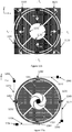
- Figure 12a illustrates a ring gyroscope according to this embodiment where N equals 4.
- the ring gyroscope comprises four outer suspenders 1271 - 1274. One end of each outer suspender is attached to an anchor point 1291 - 1294, and the other end of each outer suspender is attached to a suspension attachment point 1281 - 1284 on the ring perimeter.
- the ring gyroscope comprises four mass elements 1231 inside the ring.
- the outer suspenders In order to stabilize the ring against unwanted vibration and maintaining flexibility in the two desired resonance modes, the outer suspenders should have great flexibility radially but very little flexibility tangentially. Orienting the lengthwise direction of each outer suspender tangentially (or at least substantially tangentially), as illustrated in Figure 12a , achieves the latter aim. To achieve radial flexibility while also remaining rigid in the out-of-plane direction, the outer suspenders should be narrower in the radial direction of the ring and thick in the vertical z-direction.
- each outer suspender 1271 - 1274 may, for example, be from 1 ⁇ m to 10 ⁇ m and the thickness of each outer suspender may be from 4 to 100 ⁇ m.
- the thickness-to-width aspect ratio should at least be larger than 4, but it can be much larger.
- the length of the outer suspenders 1271 - 1274 may, for example, be 0.1 - 0.5 times the diameter of the ring.
- the preferable aspect ratio is the same in the subsequent suspender embodiments of this disclosure as well, but the optimum length may depend on the number or outer suspenders.
- suspenders 1271 - 1274 have been oriented in the same direction in Figure 12a , so that they point in the clockwise tangential direction from the suspension attachment point.
- any or all of the outer suspenders can also be oriented in the opposite direction, so that they point counter-clockwise from the suspension attachment point.
- the suspenders 1271 and 1273 could be oriented clockwise, while suspenders 1272 and 1274 could be oriented counter-clockwise.
- the suspension attachment points 1281 - 1284 are located at the points where the transversal symmetry axes T 1 and T 2 cross the ring. They could alternatively be located at the points where the diagonal symmetry axes D 1 and D 2 cross the ring. In either of these two attachment configurations, any added stiffness which each outer suspender may contribute to the ring gyroscope will act only in the direction of the symmetry axes. The direction of the resonance oscillation will remain aligned with these axes.
- the number N may be four, and each suspension attachment point may be located at a point where a transversal symmetry axis crosses the ring, or each suspension attachment point may be located at a point where a diagonal symmetry axis crosses the ring.
- N may be eight, and each suspension attachment point may be located at a point where a symmetry axis crosses the ring.
- the suspension attachment points 1281 - 1284 could also be located elsewhere on the ring perimeter. Shifting them away from the symmetry axes may slightly shift the direction of the resonance oscillation in relation to the symmetry axes (keeping in mind that the symmetry axes are defined only by the location of the piezoelectric transducers on the ring). It will depend on the stiffness of the outer suspenders if this introduces significant errors to the measurement or not. If it is not possible to place the suspension attachment points on the symmetry axes, it is preferable that they should at least be located symmetrically with respect to all symmetry axes.
- the outer suspenders 1271 - 1274 may not all have the same length and width. However, it is usually preferable to give every outer suspender the same dimensions, so that any rigidity which they may contribute to the oscillating ring at each suspension attachment point will be of equal magnitude.
- the attachment points 1281 - 1284 may be aligned with the bridge connectors of each mass element 1231, as indicated in Figure 12a . More generally, in any of the suspender embodiments presented in this disclosure, the number of mass elements may equal the number of suspension attachment points, and each suspension attachment point may be aligned on the same ring radius as one bridge connector. However, the placement of the outer suspenders does not necessarily have to be aligned with the bridge connectors as long as the outer suspenders are sufficiently flexible in comparison to the ring. These considerations about suspender dimensions and alignment with bridge connectors apply in the subsequent suspender embodiments as well.
- Figure 12b illustrates a device where four outer suspenders have been implemented together with four outer mass elements.
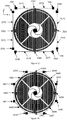
- Figure 13a illustrates an embodiment where the number N is eight, and each suspension attachment point is located at a point where a symmetry axis crosses the ring.
- Suspension attachment points 1381 are located at the points where the transversal symmetry axes cross the ring, and suspension attachment points 1382 are located at the points where the diagonal symmetry axes cross the ring.
- suspension attachment points are shifted away from these locations, it would be preferable to place them symmetrically with respect to the symmetry axes, but this is not a necessary requirement if the outer suspenders are very flexible.
- Figure 13b illustrates a device where eight outer suspenders have been implemented together with four outer mass elements.
- Figure 14 illustrates a ring gyroscope where N is sixteen and the suspension attachment points comprise a first set of eight suspension attachment points 1481 located where the transversal and diagonal symmetry axes cross the ring, and a second set of eight suspension attachment points 1482, where each suspension attachment point 1482 is located halfway between two suspension attachment points 1481 of the first set.
- the number of suspension attachment points can be increased even further if necessary.
- the suspension attachment points may be distributed symmetrically with respect to both the transversal symmetry axes and the diagonal symmetry axes.
- one or more of the outer suspender may be coated with an electrical conductor which is connected to at least one piezoelectric transducer on the ring.
- the electrical conductor may be routed to external circuitry from the corresponding anchor point.
- the outer suspenders may be utilized for transmitting electrical signals to and from piezoelectric transducers on the ring.
- the number of anchor points is N, and each anchor point is connected to only one outer suspender, and each suspension attachment point is connected to two outer suspenders which extend in opposite tangential directions from the suspension attachment point.
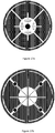
- Figure 15 illustrates a ring gyroscope according to this embodiment.
- N equals eight, so that there are eight anchor points 1591 - 1598 and eight outer suspenders 1571 - 1578, but only four suspension attachment points 1581 - 1584.
- the second suspender embodiment can also be implemented for example with N equal to sixteen. The number of suspension attachment points would in that case be eight. Any other number integer N divisible by two could in principle also be used, but the symmetry considerations stated below may pose some restrictions on this choice.
- each suspension attachment point may be located at a point where a transversal symmetry axis crosses the ring, or each suspension attachment point may be located at a point where a diagonal symmetry axis crosses the ring. This is typically the most beneficial configuration for minimizing interference in the ring resonance modes, as explained above.
- N is sixteen, each suspension attachment point may be located at a point where a symmetry axis crosses the ring. In other words, four suspension attachment points may be located where the transversal symmetry axes cross the ring, and four suspension attachment points may be located where the diagonal symmetry axes cross the ring.
- a secondary alternative is to place the suspension attachment points in locations which are not crossing points between symmetry axes and the ring, so that the suspension attachment points are placed symmetrically with respect to the symmetry axes.
- suspenders can in principle be attached anywhere on the ring if they are so flexible that their interference with the ring resonance modes can for all practical purposes be disregarded.
- the flexibility of the suspenders depends on their dimensions.
- the number of anchor points is N/2, and each anchor point is connected to two outer suspenders, and each suspension attachment point is connected to two outer suspenders which extend in opposite tangential directions from the suspension attachment point.
- Figure 16 illustrates a ring gyroscope according to this embodiment.
- N equals sixteen, so that there are eight anchor points 1691 - 1698, sixteen outer suspenders and eight suspension attachment points 1681 - 1688. If N is sixteen, each suspension attachment point may be located at a point where a symmetry axis crosses the ring, as illustrated in Figure 16 .
- each suspension attachment point may located at a point where a transversal symmetry axis crosses the ring, or each suspension attachment point may be located at a point where a diagonal symmetry axis crosses the ring.
- N divisible by two could in principle also be used, as long as the outer suspenders are long enough to reach around the perimeter of the ring, and as long as symmetry considerations are taken into account.
- Figures 17a and 17b illustrate alternative configurations for the central ring suspension, which may be combined with any of arrangement of outer suspenders presented above.
Abstract
Description
- The present disclosure relates to sensors for measuring angular rotation rates, and more particularly to z-axis gyroscopes where the oscillation of a ring-shaped structure in a given plane is utilized to detect the magnitude of angular rotation about an axis perpendicular to that plane. The present disclosure further concerns transducers which may be used to drive the primary ring oscillation, to measure the magnitude of the primary ring oscillation, to detect the secondary ring oscillation induced by angular rotation, or to drive counter-oscillation in the secondary mode. The present disclosure also concerns means for adjusting the resonance properties of the ring with attached mass elements, and means for suspending the ring from a fixed substrate.
- Microelectromechanical gyroscopes use the Coriolis effect to measure angular velocity. In vibrating MEMS gyroscopes, an object is driven into oscillating movement by an actuating drive force. This oscillation will be called "primary oscillation" or "drive oscillation" in this disclosure, and the oscillation mode will be labelled called the "primary mode". It may also be labelled the "primary resonance mode", since the ring typically vibrates in resonance. In MEMS gyroscopes the drive oscillation can involve linear or rotational oscillation of a solid inertial mass, but it can also involve flexible deformation of a ring-shaped structure. This disclosure focuses exclusively on applications of the latter kind.
- When a ring in drive oscillation undergoes an angular rotation rate Ω about the z-axis (perpendicular to the xy-plane defined by the ring), the ring is affected by the Coriolis force Fc. The magnitude and direction of the Coriolis force on a given segment of the ring is determined by the magnitude and direction of vibrational motion on that segment of the ring and by the magnitude of the angular rotation rate vector. The oscillation caused by the Coriolis force in the ring will be called "secondary oscillation" or "sense oscillation" in this disclosure, and the oscillation mode will be labelled called the "secondary mode" or the "secondary resonance mode".
-
Figure 1 illustrates the primary and secondary modes in an oscillating ring gyroscope. Thethick ring 11 illustrates the ring in its rest position, which it obtains when it is entirely at rest or when the amplitudes of all vibration modes are zero. Two transversal symmetry axes T1 and T2 and two diagonal symmetry axes D1 and D2 are illustrated in the ring shown inFigure 1 . - The primary mode involves ring vibration along the two transversal symmetry axes. The two extremes of this vibrational movement have been illustrated with dotted lines in
Figure 1 . The firstdotted line 12 shows the shape of the ring when it has expanded along the first transversal axis T1 and contracted along the second transversal axis T2, while the seconddotted line 13 shows the shape of the ring when it has expanded along the second transversal axis T2 and contracted along the first transversal axis T1. In primary oscillation the ring continuously switches between these two shapes. - When the ring undergoes an angular rotation rate Ω about the central z-axis (illustrated in the middle of the ring), segments on the ring are influenced by the Coriolis force FC. The forces FC marked on the first
dotted line 12 illustrate the local direction of the Coriolis force when the ring is expanding along the first transversal axis T1. Whensegment 121 on the right-hand side moves in the positive x-direction, FC points in the negative y-direction in this segment. Whensegment 122 on the left-hand side moves in the negative x-direction, FC points in the positive y-direction in this segment. Simultaneously,segment 123 moves in the negative y-direction and FC points in the negative x-direction in this segment.Segment 124 moves in the positive y-direction and FC points in the positive x-direction in this segment, as illustrated inFigure 1 . When the ring again contracts along the first transversal axis T1, the direction of the Coriolis forces are reversed in each segment (this situation is not illustrated). - Similarly, the forces FC marked on the second
dotted line 13 illustrate the local direction of the Coriolis force when the ring is expanding along the second transversal axis T2. Whensegment 131 moves in the negative x-direction, FC points in the positive y-direction. Whensegment 132 moves in the positive x-direction, FC points in the negative y-direction. Segment 133 moves in the positive y-direction and FC points in the positive x-direction, whilesegment 124 moves in the negative y-direction and FC points in the negative x-direction in this segment. The direction of the Coriolis forces are again reversed in each segment when the ring again contracts along the second transversal axis T2 (this situation is not illustrated). - It can be seen from
Figure 1 , that in the first vibrational extreme (12) of the ring, the Coriolis force acting on segments 121 - 124 expands the ring along the first diagonal axis D1. It simultaneously contracts the ring along the second diagonal axis D2. In the second vibrational extreme (13), the Coriolis force acting on segments 131 - 134 expands the ring along the second diagonal axis D2 and contracts it along the first diagonal axis D1. Segments 121 - 124 are the same parts of the ring as segments 131 - 134, respectively, but represent different phases of the oscillation. - For simplicity, the Coriolis force has been drawn only on these segments of the ring in
Figure 1 . In reality, the Coriolis force will act at every point of the ring along its perimeter. Each local force component is proportional to the velocity of that point of the ring and to the angular rate, and is perpendicular to both. The integral of all the Coriolis force components causes an elliptic deformation of the ring along the first and second diagonal axes D1 and D2. - In other words, in the primary resonance mode the
annular ring 11 deforms periodically toelliptic shapes nodal points 14 located at an angle of exactly 45 degrees from the transversal axes T1 and T2. Thesepoints 14 lie on the diagonal axes D1 and D2. The segments of the ring which lie at thesenodal points 14 do not experience any linear movement in primary oscillation, only rotation around the node point. - In the secondary resonance mode, the elliptical deformations are turned by 45 degrees from the primary mode axes, as explained above. Mathematically (but not geometrically), the secondary mode is orthogonal to the primary mode, since all possible oscillations of the ring can be expressed as linear combinations of these two modes.
- When the ring has been excited to the primary oscillation mode and undergoes an in-plane rotation around its center at a given rotation rate, the superposition of the two oscillations is an elliptic oscillation where the
nodal points 14 are slightly shifted from the original locations. The angular rotation rate can be detected by measuring this shift. -
- Capacitive transducers have to be manufactured near the side surfaces of the ring by placing an electrode at a distance from the side surface, so that a voltage applied between the ring and the electrode is able to deform the ring (in the primary mode), or that the deformation of the ring (in the secondary mode) can be measured by the capacitance between the ring and the electrode. Electromagnetic excitation of the primary mode requires conductors formed on the top surface of the ring which impart a force to the ring when it is placed in an external magnetic field produced by a permanent magnet.
- In these gyroscopes the detection capacitances are very small since it is very difficult to manufacture air gaps smaller than 1 µm, and the high amplitude of the primary oscillation puts limits on how far from the nodal points the secondary mode detection electrodes can be extended. On the other hand, the excitation capacitors needed for the primary mode must have a large gap to allow large amplitude oscillation, and thus the electrostatic force generated by these capacitors remains very small. If electromagnetic excitation is used, there is no space for multi-turn conductors on the ring, and a strong and large permanent magnet therefore has to be used. Such devices are typically not compatible with the standard packaging requirements of silicon devices.
- An object of the present disclosure is to provide an apparatus which alleviates the above disadvantages.
- The objects of the disclosure are achieved by an arrangement which is characterized by what is stated in the independent claims. The preferred embodiments of the disclosure are disclosed in the dependent claims.
- The disclosure is based on the idea of utilizing piezoelectric transducers for exciting the primary resonance mode in the ring gyroscope and for detecting the secondary resonance mode. Furthermore, the disclosure describes how the resonance properties of the device can be changed by fastening additional mass elements to the ring with narrow bridge connectors, and how the ring can be suspended.
- In the following the disclosure will be described in greater detail by means of preferred embodiments with reference to the accompanying drawings, in which:
-
Figure 1 illustrates the primary and secondary modes in an oscillating ring gyroscope. -
Figure 2 illustrates three cross-sections of a bending piezoelectric transducer placed on a gyroscope ring. -
Figure 3 illustrates the variation of tangential stress along the inner and outer perimeters of a gyroscope ring. -
Figure 4 illustrates a ring gyroscope. -
Figure 5 illustrates a transducer embodiment. -
Figure 6 also illustrates a transducer embodiment. -
Figure 7 also illustrates a transducer embodiment. -
Figure 8 also illustrates a transducer embodiment. -
Figures 9a - 9c illustrate ring gyroscopes. -
Figures 10a - 10e illustrate ring gyroscopes. -
Figures 11a - 11b illustrate ring gyroscopes. -
Figures 12a - 12b illustrate ring gyroscopes according to a first suspender embodiment. -
Figures 13a - 13b also illustrate ring gyroscopes according to a first suspender embodiment. -
Figure 14 also illustrates a ring gyroscope according to a first suspender embodiment. -
Figure 15 illustrates a ring gyroscope according to a second suspender embodiment. -
Figure 16 illustrates a ring gyroscope according to a third suspender embodiment. -
Figures 17a and 17b illustrate alternative configurations for the central ring suspension. -
Figure 2 illustrates three cross-sections of a bending piezoelectric transducer placed on a gyroscope ring. The transducer can generate or measure bending motion in the xy-plane. A pair of first electrode layers 241 and 242 have been placed onsilicon ring 21, one on the upper side of a layer ofpiezoelectric material 22 and one on the lower side (up and down refers in this case to the direction of the z-axis). These electrodes are paired with second electrode layers 231 and 232, respectively, as illustrated in the figure.Layers ring 21, and layers 242, 22 and 232 together form a second piezoelectric transducer on top of thering 21. - If drive voltages with opposite polarity are applied to these two transducers, the two transducers produce opposite strains in the xy-plane, which can deform
silicon ring 21. If the transducers are used as sense transducers, in-plane bending will generate a voltage differential between the two transducers. - The drawing conventions of
Figure 2 will be employed throughout this disclosure to illustrate piezoelectric transducers. In other words, two parallel rectangles of opposite colour will be used to indicate a piezoelectric transducer. For simplicity, these two parallel rectangles will primarily be referred to in the singular, as a single "split transducer", even though the structure is actually a construction which comprises two transducers. In other words, a split transducer must comprise two parallel transducers. - Black and white colours indicate transducer polarity. The ordering of the black and white rectangles in a split transducer indicate polarity so that the polarity of a transducer with a white rectangle on the outer side of the ring is opposite to the polarity of a transducer with a black rectangle on the black rectangle on the outside of the ring (as seen in the same figure).
- The
piezoelectric layer 22, which may be an aluminium nitride (AlN) layer, is typically not thicker than a few micrometers. The thickness of thesilicon ring 21 may, for example, be between 4 - 100 µm, preferably between 10 - 50 µm. - When piezoelectric transducers described in this disclosure are used in the sense mode, the largest output voltage between the electrodes of the transducer may be achieved when the transducer capacitance equals the sum of the capacitance of the external connections and the input capacitance of the amplifier. The capacitance of the transducer is determined by its area and by the thickness of the piezoelectric layer.
- The primary and secondary oscillation modes produce mechanical stress on the inner and outer perimeter of the ring. The momentary stress varies as a sinusoidal function of length along the ring perimeter. The length variable is in this case represented by the clockwise angle with respect to the T2-axis pointing in the positive y-direction in
Figure 1 .Figure 3 shows the variation of tangential stress along the inner and outer perimeters of the ring for both oscillation modes. At the illustrated moment, the stress varies as a sine-function of the angle for the primary mode and as a cosine-function for the secondary mode, and the stress on the inner perimeter is in each case equal but opposite to the stress on the outer perimeter. This stress distribution can be generated and detected by piezoelectric split transducers positioned on the top surface of the ring and lengthwise along the perimeter of the ring. A split transducer positioned on the ring for driving the primary oscillation will produce opposite and constant stress on each perimeter of the ring. - This disclosure describes a ring gyroscope which comprises a substantially circular and flexible ring which defines a ring plane, and which is flexibly suspended from a substrate so that the ring can undergo shape oscillation in the ring plane. The ring comprises first and second transversal symmetry axes in the ring plane which are orthogonal to each other, and the ring also comprises first and second diagonal symmetry axes in the ring plane which are orthogonal to each other, and the angle between each transversal symmetry axis and the adjacent diagonal symmetry axis is 45°. The gyroscope further comprises one or more primary piezoelectric split transducers configured to drive the ring into resonance oscillation, placed on first sectors of the ring, and one or more secondary piezoelectric split transducers configured to sense the oscillation of the ring, placed on one or more second sectors of the ring. Each first sector crosses a transversal symmetry axis of the ring and is symmetric with respect to that symmetry axis, and each second sector crosses a diagonal symmetry axis of the ring and is symmetric with respect to that diagonal symmetry axis of the ring.
- The gyroscope also comprises a suspension structure configured to support the weight of the ring and the mass elements, wherein the suspension structure comprises N outer suspenders, where N is an integer greater than or equal to two, and each outer suspender extends along a ring tangent from a suspension attachment point on the outer edge of the ring to an anchor point. The suspension attachment points are substantially evenly distributed along the ring perimeter, and the ratio between the vertical thickness of each outer suspender in the direction perpendicular to the ring plane and the radial width of that outer suspender in the direction of the ring radius is at least 4.
- In this disclosure, expressions such as "a piezoelectric split transducer placed on sector A of the ring" always mean that a piezoelectric split transducer is placed on top of the ring in sector A of the ring.
Figure 2 illustrates how split transducers may be placed on top of the ring. - The gyroscope may optionally comprise four or more mass elements which form a symmetrical mass distribution in relation to both the first and second transversal symmetry axes and to the first and second diagonal symmetry axes, wherein each mass element is attached to the ring from a bridge connector and the bridge connectors are evenly distributed along the ring.
- This disclosure also describes a method for using a ring gyroscope described above, wherein the method comprises the steps of: applying to at least one primary piezoelectric split transducer a drive voltage signal to generate the primary oscillation mode in the ring gyroscope, and reading from at least one secondary piezoelectric split transducer a sense voltage signal to measure the oscillation amplitude of secondary oscillation in the ring gyroscope.
- The same method can be employed with any ring gyroscope described in this disclosure.
Figure 4 illustrates a ring gyroscope which comprises aring 42. The planar ring defines the ring-plane which corresponds to the xy-plane inFigure 4 . The suspension arrangement is not illustrated. The first and second transversal symmetry axes T1 and T2, and the first and second diagonal symmetry axes D1 and D2 correspond to the symmetry axes discussed above with reference toFigure 1 . At least one primary piezoelectric splittransducer 411 has been placed on thering 42. This splittransducer 411 covers a first sector of the ring which corresponds to the angle α, as illustrated inFigure 4 . The midpoint of this sector (or, equivalently, the midpoint of the transducer 411) defines the direction of first transversal symmetry axis T1. An alternating drive voltage applied to splittransducer 411 will alternately stretch and compress thering 42 along transversal symmetry axis T1. - In other words, since a circle has infinitely many symmetry axes, the direction of the first symmetry axis can be freely selected by the placement of the first
primary split transducer 411. Once the first axis T1 has been defined, the other three symmetry axes T2, D1 and D2 have also already been uniquely defined, and the placement of subsequent primary and secondary split transducers on the ring must conform to the following requirements: - 1. A second primary piezoelectric split
transducer 412 may optionally be placed opposite to 411, on the other side of the ring. The midpoint of this secondprimary split transducer 412 must lie as close as possible to the first transversal symmetry axis T1. In other words, splittransducer 412 defines another first sector of the ring which must cross the transversal symmetry axis T1 of the ring and be symmetric with respect to that axis. In this context, symmetry means that the sector extends equally far on both sides of the axis T1. Since thesecond split transducer 412 illustrated inFigure 4 has the same polarity symmetry with respect to the center of the ring as thefirst split transducer 411, the drive voltage signal applied totransducer 412 should have the same phase as the drive voltage signal applied totransducer 411. The drive oscillations induced by these two split transducers will then reinforce each other. If the polarity of thesecond split transducer 412 with respect to the center of the ring would be opposite to the polarity oftransducer 411, the drive voltage signals should exhibit a phase difference of 180°. - 2. Third and fourth primary piezoelectric split
transducers transducers primary split transducers transducers fourth split transducer Figure 4 have the opposite polarity symmetry with respect to the center of the ring as thefirst split transducer 411, the drive voltage signal applied to splittransducers transducer 411. The ring will then be driven to contract along axis T2 when it expands along axis T1, and vice versa. If either one or both ofsplit transducers transducer 411. - 3. One to four secondary piezoelectric split transducers 431 - 434 may be placed on four sides of the ring, each shifted from the adjacent secondary split transducers by an angle of 90°. The midpoints of these secondary split transducers 431 - 434 must lie as close as possible to the either the first diagonal symmetry axis D1 or the second diagonal symmetry axis D2. As explained above, these diagonal symmetry axes are shifted from the transversal symmetry axes by an angle of 45°. Each secondary split transducer 431 - 434 defines a second sector of the ring. Each second sector must cross a diagonal symmetry axis of the ring and be symmetric with respect to that axis. As before, symmetry in this context means that the sector extends equally far on both sides of the diagonal symmetry axis. The polarity of the secondary split transducers with respect to the center of the ring may chosen freely.
Figure 4 illustrates the simplest alternative where the polarity ofsecondary split transducers secondary split transducers - In other words, at least one primary piezoelectric split transducer should be present on the ring to excite the primary resonance motion of the ring. This excitation is achieved by applying an alternating voltage to the primary piezoelectric split transducer, with a frequency which is equal or close to the resonance frequency of the ring. The primary piezoelectric split transducers should preferably be placed symmetrically in relation to a transversal symmetry axis of the ring.
- Additionally, at least one secondary piezoelectric split transducer should be present on the ring to detect the oscillation coupled by the Coriolis force when the ring rotates about its central axis which is perpendicular to the ring plane. The secondary piezoelectric split transducers should preferably be placed symmetrically in relation to a diagonal symmetry axis of the ring.
- Misalignment of any first or second sector (i.e. any primary or secondary transducer) will induce unwanted coupling of primary oscillation into the secondary oscillation mode. This is a because a misaligned primary transducer 411 - 414 will generate oscillation which puts the adjacent
nodal point 44 in motion, even though thenodal points 44 should remain stationary when the ring oscillates only in the primary resonance mode. The oscillation of thenodal point 44 will be picked up by secondary split transducers 431 - 434 and create an erroneous sense signal. Conversely, a misaligned secondary transducer will be centered at a point which differs from thenodal point 44, which also leads it to pick up the primary resonance oscillation and to produce an erroneous sense signal. If, on the other hand, all primary and secondary split transducers are perfectly aligned, then secondary split transducers 431 - 434 will only pick up the true secondary resonance mode, which is the oscillation ofnodal points 44 induced by the Coriolis force. - A single primary piezoelectric split transducer on a first sector of the ring and a single secondary split transducer on a second sector of the ring is sufficient for operating the ring gyroscope. However, to improve the signal-to-noise ratio and reduce the possibility of errors due to misalignment, the number of both primary and secondary split transducers may be increased according to geometry illustrated as illustrated in
Figure 4 . - In other words, the gyroscope may comprise a first pair of primary piezoelectric split
transducers ring 42. Optionally, the gyroscope may also comprise a second pair of primary piezoelectric splittransducers ring 42. The first pair of primary piezoelectric splittransducers ring 42 which is opposite to the polarity-symmetry of the second pair ofpiezoelectric split transducers ring 42. - Furthermore, the gyroscope may comprise a first pair of secondary
piezoelectric split transducers ring 42. Optionally, the gyroscope may also comprise a second pair of secondarypiezoelectric split transducers ring 42. The first pair of secondarypiezoelectric split transducers ring 42 which is opposite to the polarity-symmetry of the second pair of secondarypiezoelectric split transducers ring 42. - In the ring gyroscope illustrated in
Figure 4 , the width of each first sector and each second sector is 45°. In other words, the length of each primary split transducer 411 - 414 and the length of each secondary split transducer 431 - 433 is equal to 1/8 of the ring circumference. InFigure 4 , where there are eight split transducers in total, the primary and secondary split transducers together cover the entire circumference of the ring. This maximizes the force obtained from the primary transducers and the sense signal strength obtained from the secondary transducers. - However, sometimes some of the area on the top surface of the ring may be needed for other purposes than force transduction, for example drive amplitude monitoring, coupling cancellation or electrical contacting.
-
Figure 5 illustrates a ring gyroscope according to another transducer embodiment. Reference numbers 511 - 514, 531 - 534, 52 and 54 correspond to reference numbers 411 - 414, 431 - 434, 42 and 44, respectively inFigure 4 . InFigure 5 , the width of each first sector is less than 45°, and the width of each second sector is less than 45°. For illustrative purposes the length of each transducer is 1/16 of the ring circumference, so that the corresponding width of each first and second sector is 22.5°, but transducer lengths can be selected freely. The symmetry criterion remains the same as inFigure 4 : each first and second sector should be symmetric with respect to the symmetry axis which it crosses. Deviations from this symmetry will cause unwanted coupling of primary mode oscillation into the secondary mode, as described above. -
Figure 6 illustrates an alternative transducer embodiment where the width of all first sectors and two second sectors is less than 45°, and the width of the two other second sectors is 45°. Reference numbers 611 - 614, 631 - 634, 62 and 64 correspond to reference numbers 511 - 514, 531 - 534, 52 and 54, respectively, inFigure 5 . Alternatively, the width of each first sector may be less than 45°, and the width of each second sector may be 45°. These configurations, which open up some room on the ring surface by narrowing the first sectors, can be advantageous when driving force can be sacrificed but sense signal strength cannot. The force required for driving the primary oscillation depends on the dimensions of the ring, the length of the primary transducers and the amplitude of the drive voltage signal applied to these primary transducers. As before, each first and second sector must still be symmetric with respect to the symmetry axis which it crosses. - When the ring gyroscope is used in closed-loop servo mode, or when the secondary mode resonance is damped by closed loop feedback, at least one secondary piezoelectric split transducer may be driven with an alternating voltage so that it actively cancels the coupling of the primary oscillation into the secondary. The lengths of the secondary transducers which are dedicated to active cancelling may then differ from the lengths of the secondary transducers which sense the secondary oscillation.
- Alternatively, the width of each first sector may be 45°, and the width of each second sector may be less than 45°. This configuration can be advantageous for freeing space on the ring when the driving force must be maximized, but some of the sense signal strength can be sacrificed. This option is not separately illustrated, but it corresponds directly to
Figure 6 , except that each primary split transducer would cover 1/8 of the ring circumference, while no secondary split transducer would cover that much of the circumference. - All primary split transducers do not necessarily have to be used for driving the primary oscillation. Some of them may, for example, be used for measuring the amplitude of the primary oscillation. This is needed for maintaining stable oscillation amplitude independent of the changes in the driving frequency or the Q-value of the resonator due to environmental variables or aging.
- In other words, a method for using any ring gyroscope described in this disclosure may comprise the step of reading from at least one primary piezoelectric split transducer a third voltage signal to measure the oscillation amplitude of primary oscillation in the ring gyroscope.
- Similarly, all secondary split transducers do not necessarily have to be used for measuring the secondary oscillation. Some of them may, for example, be used for active interventions into the secondary oscillation mode. For example, when the ring gyroscope is used in closed-loop servo mode, or when the secondary mode resonance is damped by closed loop feedback, or when an applied electromechanical force is used to cancel a quadrature signal, at least one secondary piezoelectric split transducer may be driven with an alternating voltage so that it actively cancels the coupling of the primary oscillation into the secondary oscillation. The lengths of the secondary transducers which are dedicated to active cancelling may differ from the lengths of the secondary transducers which sense the secondary oscillation.
- In other words, a method for using any ring gyroscope described in this disclosure may comprise the step of applying to at least one secondary piezoelectric split transducer a fourth voltage signal to actively cancel the coupling of the primary oscillation into the secondary oscillation.
- If the primary and secondary split transducers do not together cover the entire circumference of the ring, the vacant surface area (for example, the unused area on the ring in
Figures 5 and 6 ) can be used for other purposes.Figure 7 illustrates an alternative embodiment where reference numbers 711 - 714, 731 - 734, 72 and 74 correspond to reference numbers 611 - 614, 631 - 634, 62 and 64, respectively, inFigure 6 . In this embodiment, the width of at least one first or second sector is less than 45°. The gyroscope comprises one or more tertiary piezoelectric split transducers on third sectors of the ring, which do not overlap with the first sectors or the second sectors. - Eight tertiary piezoelectric split transducers 751 - 758 are illustrated in
Figure 7 . The number of tertiary piezoelectric split transducers could be smaller, and it may depend on the widths of the primary and secondary transducers. The number of tertiary piezoelectric split transducers may also be larger than eight. Several third sectors may fit between first and second sectors. - One or more of the tertiary piezoelectric transducers 751 - 758 may be used for detecting the amplitude of the primary oscillation. This amplitude may not remain constant during the lifetime of the device due to temperature stress and other aging effects. Drift in the drive amplitude will immediately introduce a proportional error in the sensed amplitude, but this error can be corrected if the primary oscillation is monitored.
- In other words, a method for using a ring gyroscope which comprises one or more tertiary piezoelectric split transducers on third sectors of the ring which do not overlap with the first sectors or the second sectors may comprise the step of reading from at least one tertiary piezoelectric split transducer a fifth voltage signal to measure the oscillation amplitude of primary oscillation in the ring gyroscope.
- One or more of the tertiary piezoelectric transducers 751 - 758 may also be used for cancelling coupled oscillation when the gyroscope is used in closed loop servo mode or when the secondary resonance mode is actively damped by closed-loop feedback, or when electromechanical force is used to cancel a quadrature signal, as described above.
- In other words, a method for using a ring gyroscope which comprises one or more tertiary piezoelectric split transducers on third sectors of the ring which do not overlap with the first sectors or the second sectors may comprise the step of applying to at least one tertiary piezoelectric split transducer a sixth voltage signal to actively cancel the coupling of the primary oscillation into the secondary oscillation.
-
Figure 8 illustrates an alternative embodiment where reference numbers 811 - 814, 831 - 834, 855 - 856, 82 and 84 correspond to reference numbers 711 - 714, 731 - 734, 755 - 756, 72 and 74, respectively, inFigure 7 . In this embodiment, three of the secondary transducers on the second sectors, 831-833, have a width larger than 45°, and the fourth one, 834, has a width less than 45°. All of these secondary transducers are used for detecting the secondary oscillation. All transducers on the primary sectors, 811-814, have a width less than 45°, and they are used for exciting the primary oscillation. There are only two tertiary transducers on third sectors, 855 and 856. One of these tertiary transducers is used for detecting the amplitude of the primary oscillation, as described above. The other is used for cancelling coupled oscillation when the gyroscope is used in closed loop servo mode or when the secondary resonance mode is actively damped by closed-loop feedback, or when electromechanical force is used to cancel a quadrature signal, as described above. - As indicated visually in
Figure 8 , the whole perimeter of the ring may be fully covered by transducers for the described functions. The gyroscope may be optimized by selecting optimum transducer lengths for each function, so that sufficiently high signal-to-noise ratios for the primary and secondary signals while keeping the voltages for driving the primary oscillation and for compensating the secondary oscillation by applied electromechanical force suitably low. - Certain design tradeoffs may be required when piezoelectric transducers are fabricated on the top surface of the ring. A practical split electrode transducer requires at least 15 µm, preferably more than 20 µm of width. A silicon ring with an outer diameter of 1000 µm and a width 6.8 µm has a 30 kHz resonant frequency, but it is nearly impossible to manufacture piezoelectric split-transducers on the top surface of such a narrow ring.
- In order to implement piezoelectric transduction on a basic gyroscope ring, the width of the ring must be increased. This increases the resonance frequency. A ring width of 15 µm increases the resonance frequency to 67 kHz. But even this may be too narrow, because the total maximum capacitance of a 15 µm wide split transducer with a 1 µm AIN layer is only 3,8 pF, which will be shared with many functions in addition to sensing the secondary oscillation: e.g. driving the primary oscillation, sensing the magnitude of the primary oscillation and driving a compensating signal in the secondary mode to cancel the secondary oscillation in a closed feed-back loop and/ or damping the secondary resonance and/ or cancelling the quadrature signal. For perfect match to the surrounding electronics, the total capacitance should preferably be 7-15 pF since it is not easy to use more than 50% of the maximum capacitance for sensing the secondary oscillation.
- Increasing ring width to 30 µm makes the capacitance 7.6 pF, but the corresponding resonance frequency is then 140 kHz. At high frequency operation the gyroscope becomes more immune to external vibrations, which are predominantly at lower frequencies, but the quadrature signal due to direct mechanical coupling of the primary mode to the secondary transducers also increases with frequency.
- An obvious way to increase the width of the ring and the capacitance without too much increasing the resonant frequency is to increase the diameter of the ring. If the diameter is chosen 1.6 mm and the width 18 µm the resonant frequency will be 31 kHz and the capacitance 7.2 pF which numbers are close to an ideal target. But this gyroscope will have 2.5 times as large area and thus 2.5 times as large manufacturing cost as the 1 mm diameter gyroscope.
- These design tradeoffs can be alleviated by fastening additional mass elements to the ring. These mass elements may be shaped like partial circle sectors inside the ring or like corner elements with perpendicular sides outside of the ring. Other shapes are also possible, as described below. These additional mass elements cannot be attached to the ring from fasteners which cover a large proportion of the ring perimeter, because it will lead to a loss of elastic flexibility in the ring. However, if each mass is attached to the ring from a fastener shaped like a narrow bridge, the elasticity of the ring and its spring constant (i.e. force/ deformation ratio) can be maintained even when a significant amount of additional mass is added to the oscillating system. Since the resonant frequency depends on the spring constant / mass ratio, the additional mass elements can be used to reduce the resonance frequency of the system without having to use an excessively narrow ring.
-
Figure 9a illustrates an exemplary ring gyroscope according to one embodiment. Piezoelectric transducers have been omitted from the figure to preserve clarity, but any of the transducer embodiments described above can be implemented with any of the embodiments described in this disclosure. In other words,reference number 92 inFigure 9a may correspond to any of thereference numbers Figure 9a shows aring 92 with 32 smallmass elements 93, all of which are located inside the ring. Eachmass element 93 is shaped like a partial circle sector within the ring, but other shapes may also be used. - Each
mass element 93 is attached to the ring from abridge connector 94. The width of a bridge connector along the ring periphery is substantially less than the width of the correspondingmass element 93 along the ring periphery to ensure that the flexibility of the ring is affected as little as possible by the mass elements which have been added to the ring. Thebridge connector 94 must nevertheless be sufficiently wide to support the weight of themass element 93. The minimum width therefore depends on the size of the mass element. In the vertical z-direction perpendicular to the xy-plane thebridge connector 94 may be as high themass element 93 and thering 92, because the in-plane flexibility of thering 92 does not depend on the vertical height of thebridge connector 94. The radial length of thebridge connector 94 should be as small as possible, limited by the required clearance between the ring and the mass element to allow large amplitude primary oscillation and by manufacturing tolerances. The radial length should be small enough so that any bending of the bridge connector is negligible compared to the elastic deformation of the ring in the primary and secondary oscillation modes. - The mass distribution produced by the sum of all
mass elements 93 must be symmetric in relation to both the first and second transversal symmetry axes T1 and T2 and to the first and second diagonal symmetry axes D1 and D2 in order to maintain the two elliptical resonance modes of the ring at 45° angle as shown in inFigure 1 and explained above, and not to introduce any other low order in-plane resonance modes. This is needed to maintain the basic benefits of a ring gyroscope: to achieve a high Q-value of the resonance without any oscillation energy leaking out and to achieve good robustness to external linear and angular vibrations. - 1. There are many ways to preserve the required symmetry. The configuration illustrated in
Figure 9a can more generally be described as a configuration where the number of mass elements is 4N, where N is an integer greater than zero, and the mass elements are distributed symmetrically with respect to both the transversal and diagonal symmetry axes. InFigure 9a , the number of mass elements is 32, and no mass element crosses a symmetry axis.Figure 9b illustrates a ring gyroscope with 32 elements where every fourth mass element crosses a symmetry axis. - 2. The mass elements do not necessarily have to be of equal size.
Figure 9c illustrates a configuration with four largermass elements 931 and eight smallermass elements 932. The mass elements are nevertheless distributed symmetrically with respect to all symmetry axes. - It can be showed that in a ring with no mass elements attached, the effective moving mass for one oscillation mode is 29.7% of the total ring mass. With the additional
mass elements 93 inFigures 9a and 9b , the moving mass is considerably increased without affecting the spring constant of the ring. If the radial length of the mass elements inFigure 9a or 9b is 200 µm, a ring width of 20 µm can produce a resonant frequency at 30 kHz. Without the addedmass elements 93, the resonant frequency of the 20 µm wide ring would be 91 kHz. Looking at it from another perspective, with the additional mass elements the effective moving mass in one oscillation mode becomes 25 times larger than the effective mass in one oscillation mode when only a 6.8 µm wide ring (suitable for producing a resonance frequency of 30 kHz) is used. In other words, 25 times the original oscillation energy is stored in the resonating system when these additional mass elements are used, which results in an output signal amplitude which is 5 times greater than the original maximum output signal. The total capacitance of the 20 µm wide set of transducers would be 4.9 pF if 1 µm AIN is used. - If the desired resonance frequency would be 50 kHz, a bare ring without mass elements would have to be only 11 µm of wide to achieve the desired frequency. This is too narrow for a piezoelectric transducer. Assuming again that the radial length of the
mass elements 93 inFigure 9a and 9b would be 200 µm, the presence of the mass elements increases the available width to 28 µm while still maintaining the resonant frequency at 50 kHz. The energy of the oscillation is in this case increased by a factor of 16, and the signal amplitude by a factor of 4, compared to the gyroscope without added mass elements. The total transducer capacitance is increased to 6.8 pF. If the radial length of themass elements 93 is increased to 370 µm, the ring width can be increased to 31 µm at 50 kHz resonant frequency. The total capacitance will then be 7.5 pF. - If the ring diameter is approximately 1000 µm, a suitable radial length of the mass elements may, for example, be in the range 50 - 500 µm, 100 - 400 µm, or 200 - 300 µm. The ring width may, for example, be 15 - 50 µm, 20 - 40 µm or 25 - 35 µm. If the ring diameter is larger than 1000 µm, the radial length of the mass elements and the ring width may be increased in the same proportion.
- Although the distribution of mass elements which is illustrated in
Figure 9a and 9b increases the oscillating mass in the ring gyroscope, the whole of the added mass is not fully contributing to the moving mass of the oscillating mode. The primary oscillation of the ring will move the mass elements radially. But the amount of radial motion is reduced at locations away from the primary axes. At the location on the perimeter at 45° angle from the primary axis there will be no radial motion at all. The oscillation will also bend the bridge connectors to some extent, because all portions of the ring perimeter which are not located precisely on a crossing point with a symmetry axis will undergo a rotation in addition to the radial movement. At the location on the perimeter at 45° angle from the primary axis, there will be only a rotation. This rotation will bend the bridge connector slightly, swing the attached mass sideways and introduce an additional tangential motion in addition to the radial motion of the mass elements. The radial component of the motion is, however, much reduced for mass elements away from the primary axes and is zero at 45° angle and thereby the attached mass elements away from the primary axes are not fully contributing to the moving mass of the oscillation although the tangential motion may to some extent compensate for the reduced radial motion, especially if the mass elements are radially rather long. -
Figures 10a - 10e illustrate exemplary ring gyroscopes according to an alternative embodiment. In this embodiment, the size of the mass elements has been increased, and their number decreased.Figure 10a illustrates an embodiment where allmass elements - The ring gyroscope in
Figure 10a comprises fourmass elements 1031 which cross a transversal symmetry axis, and fourmass elements 1032 which cross a diagonal symmetry axis. Themass elements 1031 are attached to thering 102 withbridge connectors 1041 which cross the same transversal symmetry axis as the mass element. Themass elements 1032 are attached to thering 102 withbridge connectors 1042 which cross the same diagonal symmetry axis as the mass element. Due to the greater size of themass elements mass elements 93, thebridge connectors bridge connectors 94 inFigures 9a and 9b . - In the mass element distribution illustrated in
Figure 10a ,mass elements 1031 will move back and forth along the transversal symmetry axes T1 and T2 in drive oscillation. When sense oscillation occurs,mass elements 1032 will correspondingly move back and forth along the diagonal symmetry axes D1 and D2. The best signal-to-noise ratio is typically obtained when the resonance frequency of the primary mode equals the resonance frequency of the secondary mode. This balance is obtained in the configuration inFigure 10a when each mass element occupies an equally wide partial circle sector. The width of each partial circle sector may for example be 45°. -
Figure 10b illustrates an alternative embodiment where the mass elements comprise innermass elements ring 102 and outermass elements 1033 which are located outside thering 102. As inFigure 10a , the number of inner mass elements is eight, and eachinner mass element mass elements 1033 is four, and eachouter mass element 1033 is placed so that it crosses a diagonal symmetry axis, so that it is symmetric in relation to that diagonal symmetry axis, and so that itsbridge connector 1043 is centered on that diagonal symmetry axis. - The outer
mass elements 1033 are attached to thering 102 withbridge connectors 1043 which cross the same diagonal symmetry axis as the mass element. When sense oscillation occurs,mass elements 1033 will move back and forth along the diagonal symmetry axes D1 and D2. - The mass element distribution illustrated in
Figure 10b is convenient for utilizing all of the available area in square-shaped ring gyroscope components. When the gyroscope includes both inner and outer mass elements, the equalization of primary and secondary mode resonance frequencies may for example be obtained by letting theinner mass elements 1032, which cross the transversal symmetry axes, occupy narrower partial circle sectors than theinner mass elements 1031, which cross the diagonal symmetry axes. This option is illustrated inFigure 10b . The combined area of one outer+innermass element pair 1032+1033 may be equal to area of oneinner mass element 1031. - The inner mass elements do not necessarily have to be shaped like partial circle sectors.
Figure 10c illustrates a ring gyroscope where theinner mass elements - In the configurations illustrated in
Figures 10a- 10c , four mass elements, 50% of the total mass, are connected to the ring at the crossings of the transversal symmetry axes and they will exhibit pure radial motion in the primary oscillation mode. The four mass elements connected to the ring at the crossings of the diagonal symmetry axes will exhibit a combination of tangential and rotary motion in the primary oscillation mode. The total effective moving mass of the primary mode is thus much more than 50% of the total mass, which is much more than the 29.7% for evenly distributed small mass elements without significant tangential and rotary motion. The same is true for the secondary oscillation mode. - By way of example,
Figure 10d illustrates the motion of the mass elements during primary oscillation. Nodal points 1051 - 1054 are radially stationary in this resonance mode, but these points will exhibit rotation according to the elliptic mode shape. Each pair of inner and outer mass elements undergoes a rotational movement around an axis which is perpendicular to the xy-plane and passes through the nodal point between the mass elements, and there will also be a net tangential component of the motion if the center of gravity of the pair of masses doesn't coincide with the corresponding nodal point. This movement, as well as the radial movement of the mass elements which cross the transversal axes, is indicated with white arrows and they all contribute to the motion in the primary oscillation mode and thus to the energy stored in the mode. In the oscillation phase illustrated inFigure 10d , thepairs 10321+10331 and 10323+10333 move in the clockwise direction in relation tonodal points pairs 10322+10332 and 10324+10334 move in the counter-clockwise direction in relation tonodal points -
Figure 10e illustrates the effect of similar radial motion and rotation of the nodal points during secondary oscillation. The nodal points on the axes D1 and D2 are now in pure radial motion, and the inner and outer mass elements which cross the diagonal symmetry axes therefore move only radially. The inner mass elements 10311 - 10314 which cross the transversal symmetry axes, on the other hand, are not in radial motion at all, but undergo a rotation around an axis which is perpendicular to the xy-plane and passes through the respective symmetry point 1061 - 1064 on the ring. Since the center of gravity of each mass element is offset from the corresponding nodal point the elements will exhibit also a significant tangential motion. In the oscillation phase illustrated inFigure 10e , themass elements symmetry points pairs symmetry points - Attachment of the four mass elements at the nodal points for each mode will increase the effective moving mass for each mode to 50% of the total mass of the elements. This is a significant improvement from the case with distributed added mass in only radial mode, as in
Figure 9a and 9b , where only 29.7 % of the total mass, similar to the pure ring, will contribute to each mode. In the secondary mode the sensor output signal will be 30% higher. The width of the ring can be increased by 10% with the same resonant frequency, increasing thus the capacitance. Alternatively, the diameter of the ring can be reduced by 10%. - The rotary and tangential motions of the mass elements described above further increase the motional energy to the oscillation mode. The effective motional mass for each mode will be much over 50% and up to 100% of the total mass of the elements, which is a great improvement compared to the distributed added mass in only radial mode as in
Figure 9a and 9b , where only 29.7 % of the total mass, similar to the pure ring, will contribute to each mode. In the secondary mode the sensor output signal will be 30 - 83% higher. The width of the ring can be increased by 10 - 22% with the same resonant frequency increasing thus the capacitance or alternatively, the diameter of the ring can be reduced by 10 - 22%. - If the ring gyroscopes illustrated in
Figures 10a - 10e are made of single crystal silicon, if the ring diameter is 1000 µm diameter ring, if the resonance frequency is 30 kHz, if the diameter of the center hole is 200 µm, and if piezo-transducers with 1 µm thick AIN film are utilized on the ring, then the ring can be 28 µm wide and the total transducer capacitance will be 6.8 pF. If the frequency is increased to 50 kHz, the ring can be 39 µm wide and the capacitance will be 9.4 pF. The latter design may be optimal for matching the capacitance to a practical amplifier circuit. -
Figures 11a - 11b illustrate exemplary ring gyroscopes according to alternative embodiments. In these embodiments, the size of the mass elements has again been increased compared to the previous embodiment, and their number has been decreased.Figure 11a illustrates an embodiment where the mass elements comprise innermass elements 1131 which are located inside the ring and outermass elements 1133 which are located outside the ring. The number of inner mass elements is four, and each inner mass element is placed so that it crosses a diagonal symmetry axis, so that it is symmetric in relation to that diagonal symmetry axis, and so that its bridge connector is centered on that diagonal symmetry axis. The number of outer mass elements is four, and each outer mass element is placed so that it crosses a diagonal symmetry axis, so that it is symmetric in relation to that diagonal symmetry axis, and so that its bridge connector is centered on that symmetry axis. - The mass element configuration illustrated in
Figure 11a maximizes the mass contribution to primary and secondary oscillation to 100% of the total mass of mass elements, since all mass elements are attached to the ring at the nodal points and move equally in each mode. This is a great improvement compared to the distributed added mass in only radial mode as inFigure 9a and 9b , where only 29.7 % of the total mass, similar to the pure ring, will contribute to each mode. In the secondary mode the sensor output signal will be 83% higher. The width of the ring can be increased by 22% with the same resonant frequency increasing thus the capacitance. Alternatively, the diameter of the ring can be reduced by 22%. - In
Figure 11a , the motion of eachmass element inner mass elements 1131 cross a diagonal symmetry axis, no mass element moves back and forth radially in primary oscillation. Instead, allmass elements Figure 11a . The motion of eachmass element - The ring gyroscope may alternatively be implemented with four mass elements located inside the ring, positioned like the
inner mass elements 1131 inFigure 11a , and with no outside mass elements. In this case the number of mass elements is four, and each mass element is placed so that it crosses a diagonal symmetry axis, so that it is symmetric in relation to that diagonal symmetry axis, and so that its bridge connector is centered on that symmetry axis. This configuration has not been separately illustrated. The movement of the mass elements in this configuration during primary and secondary oscillation will be the same as the movement which was illustrated with arrows formass elements 1131 inFigure 11a . -
Figure 11b illustrates another embodiment where the mass elements comprise innermass elements 1131 which are located inside the ring and outermass elements 1133 which are located outside the ring In this case the number of innermass elements 1131 is four, and each inner mass element is placed so that it crosses a transversal symmetry axis, so that it is symmetric in relation to that transversal symmetry axis, and so that its bridge connector is centered on that transversal symmetry axis. The number of outermass elements 1133 is four, and each outer mass element is placed so that it crosses a diagonal symmetry axis, so that it is symmetric in relation to that diagonal symmetry axis, and so that its bridge connector is centered on that symmetry axis. - As in the previous figure, the motion of each
mass element Figure 11b with thick white arrows. In the opposite phase of primary oscillation, the motion of each mass element is in the reverse direction. Since all of theinner mass elements 1131 cross a transversal symmetry axis, the inner mass elements move back and forth radially in primary oscillation. The outer mass elements move in a tangential direction in primary oscillation. The motion of eachmass element mass elements 1133 move radially along the diagonal symmetry axes, while innermass elements 1131 move tangentially. - The mass element configuration illustrated in
Figure 11a maximizes the mass contribution to primary oscillation to 100% of the total mass of mass elements, since all mass elements are attached to the ring at the nodal points and move equally in each mode. This is a great improvement compared to the distributed added mass in only radial mode as inFigure 9a and 9b , where only 29.7 % of the total mass, similar to the pure ring, will contribute to each mode. In the secondary mode the sensor output signal will be 83% higher. The width of the ring can be increased by 22% with the same resonant frequency increasing thus the capacitance or alternatively, the diameter of the ring can be reduced by 22%. - As in the previous example, the ring gyroscope may alternatively be implemented with four mass elements located inside the ring, positioned like the
inner mass elements 1131 inFigure 11b , and with no outside mass elements. In this case the number of mass elements is four, and each mass element is placed so that it crosses a transversal symmetry axis, so that it is symmetric in relation to that transversal symmetry axis, and so that its bridge connector is centered on that symmetry axis. This configuration has not been separately illustrated. The movement of the mass elements in this configuration during primary and secondary oscillation will be the same as the movement which was illustrated with arrows formass elements 1131 inFigure 11b . - Alternatively, mass elements are located outside the ring. The number of mass elements is then four, and each mass element is placed so that it crosses a diagonal symmetry axis, so that it is symmetric in relation to that diagonal symmetry axis, and so that its bridge connector is centered on that symmetry axis. This configuration has not been separately illustrated. The movement of the mass elements in this configuration during primary and secondary oscillation will be the same as the movement which was illustrated with arrows for outer
mass elements 1133 inFigures 11a and11b . - If the ring gyroscopes illustrated in
Figures 11a and11b are made of single crystal silicon material, if they are designed with a 1000 µm ring diameter and a 30 kHz resonant frequency, if the hole diameter at the center of the ring if 200 µm, and if the ring is provided with piezo-transducers with a 1 µm AIN film, then the ring width can be 28 µm and the total transducer will be capacitance 6.8 pF. If the frequency is increased to 50 kHz, the ring can be 39 µm wide and the capacitance will be 9.4 pF. The latter design may be optimal for matching the capacitance to a practical amplifier circuit. - Ring gyroscopes are fixed to a substrate with one or more suspenders, which should be sufficiently rigid to support the weight of the ring, but sufficiently flexible not to disturb either resonance mode. Furthermore, the suspenders should preferably stiffen the ring gyroscope in unwanted out-of-plane vibration modes and stiffly suspend it in both in-plane and out-of-plane directions so that unwanted in-plane and out-of-plane translation and rotation, which may arise from external vibrations, are minimized. It can be challenging to meet all of these criteria especially when the ring gyroscope includes added mass elements.
- Any suspender embodiment described below can be combined with any of the preceding embodiments discussed in this disclosure. Piezoelectric transducers have been omitted from the figures to preserve clarity. Furthermore, the transversal and diagonal symmetry axes have also been omitted for clarity, but their location in the Figure is the same as in all of the preceding figures.
- In the following suspender embodiments, four mass elements are illustrated. However, the number of mass elements can also be different. Each of the following suspender embodiments must be combined with an inner suspension arrangement which supports either the ring, or the mass elements located inside the ring, on the inside of the ring. A spiralling suspension arrangement is illustrated inside the ring in each suspender embodiment. Alternative inner suspension arrangements are illustrated at the end of this disclosure.
- Mass elements are shown in the figures which illustrate the first, second and third suspender embodiments because the need for effective suspension is especially critical when the total mass of the oscillating system increases. However, each suspender embodiment may alternatively be implemented without any mass elements attached to the ring.
- According to a first suspender embodiment, the number of anchor points is N and each anchor point and each suspension attachment point is connected to only one outer suspender.
Figure 12a illustrates a ring gyroscope according to this embodiment where N equals 4. The ring gyroscope comprises four outer suspenders 1271 - 1274. One end of each outer suspender is attached to an anchor point 1291 - 1294, and the other end of each outer suspender is attached to a suspension attachment point 1281 - 1284 on the ring perimeter. The ring gyroscope comprises fourmass elements 1231 inside the ring. - In order to stabilize the ring against unwanted vibration and maintaining flexibility in the two desired resonance modes, the outer suspenders should have great flexibility radially but very little flexibility tangentially. Orienting the lengthwise direction of each outer suspender tangentially (or at least substantially tangentially), as illustrated in
Figure 12a , achieves the latter aim. To achieve radial flexibility while also remaining rigid in the out-of-plane direction, the outer suspenders should be narrower in the radial direction of the ring and thick in the vertical z-direction. - The radial width of each outer suspender 1271 - 1274 may, for example, be from 1 µm to 10 µm and the thickness of each outer suspender may be from 4 to 100 µm. The thickness-to-width aspect ratio should at least be larger than 4, but it can be much larger. The length of the outer suspenders 1271 - 1274 may, for example, be 0.1 - 0.5 times the diameter of the ring. The preferable aspect ratio is the same in the subsequent suspender embodiments of this disclosure as well, but the optimum length may depend on the number or outer suspenders.
- All four suspenders 1271 - 1274 have been oriented in the same direction in
Figure 12a , so that they point in the clockwise tangential direction from the suspension attachment point. However, any or all of the outer suspenders can also be oriented in the opposite direction, so that they point counter-clockwise from the suspension attachment point. For example, thesuspenders suspenders - In
Figure 12a , the suspension attachment points 1281 - 1284 are located at the points where the transversal symmetry axes T1 and T2 cross the ring. They could alternatively be located at the points where the diagonal symmetry axes D1 and D2 cross the ring. In either of these two attachment configurations, any added stiffness which each outer suspender may contribute to the ring gyroscope will act only in the direction of the symmetry axes. The direction of the resonance oscillation will remain aligned with these axes. In other words, the number N may be four, and each suspension attachment point may be located at a point where a transversal symmetry axis crosses the ring, or each suspension attachment point may be located at a point where a diagonal symmetry axis crosses the ring. Alternatively, N may be eight, and each suspension attachment point may be located at a point where a symmetry axis crosses the ring. - The suspension attachment points 1281 - 1284 could also be located elsewhere on the ring perimeter. Shifting them away from the symmetry axes may slightly shift the direction of the resonance oscillation in relation to the symmetry axes (keeping in mind that the symmetry axes are defined only by the location of the piezoelectric transducers on the ring). It will depend on the stiffness of the outer suspenders if this introduces significant errors to the measurement or not. If it is not possible to place the suspension attachment points on the symmetry axes, it is preferable that they should at least be located symmetrically with respect to all symmetry axes.
- The outer suspenders 1271 - 1274 may not all have the same length and width. However, it is usually preferable to give every outer suspender the same dimensions, so that any rigidity which they may contribute to the oscillating ring at each suspension attachment point will be of equal magnitude. The attachment points 1281 - 1284 may be aligned with the bridge connectors of each
mass element 1231, as indicated inFigure 12a . More generally, in any of the suspender embodiments presented in this disclosure, the number of mass elements may equal the number of suspension attachment points, and each suspension attachment point may be aligned on the same ring radius as one bridge connector. However, the placement of the outer suspenders does not necessarily have to be aligned with the bridge connectors as long as the outer suspenders are sufficiently flexible in comparison to the ring. These considerations about suspender dimensions and alignment with bridge connectors apply in the subsequent suspender embodiments as well. -
Figure 12b illustrates a device where four outer suspenders have been implemented together with four outer mass elements. -
Figure 13a illustrates an embodiment where the number N is eight, and each suspension attachment point is located at a point where a symmetry axis crosses the ring. Suspension attachment points 1381 are located at the points where the transversal symmetry axes cross the ring, and suspension attachment points 1382 are located at the points where the diagonal symmetry axes cross the ring. As above, if the suspension attachment points are shifted away from these locations, it would be preferable to place them symmetrically with respect to the symmetry axes, but this is not a necessary requirement if the outer suspenders are very flexible. -
Figure 13b illustrates a device where eight outer suspenders have been implemented together with four outer mass elements. -
Figure 14 illustrates a ring gyroscope where N is sixteen and the suspension attachment points comprise a first set of eight suspension attachment points 1481 located where the transversal and diagonal symmetry axes cross the ring, and a second set of eight suspension attachment points 1482, where eachsuspension attachment point 1482 is located halfway between two suspension attachment points 1481 of the first set. The number of suspension attachment points can be increased even further if necessary. - In any of the suspender embodiments presented in this disclosure, the suspension attachment points may be distributed symmetrically with respect to both the transversal symmetry axes and the diagonal symmetry axes.
- In any of the suspender embodiments presented in this disclosure, one or more of the outer suspender may be coated with an electrical conductor which is connected to at least one piezoelectric transducer on the ring. The electrical conductor may be routed to external circuitry from the corresponding anchor point. In other words, the outer suspenders may be utilized for transmitting electrical signals to and from piezoelectric transducers on the ring.
- According to a second suspender embodiment, the number of anchor points is N, and each anchor point is connected to only one outer suspender, and each suspension attachment point is connected to two outer suspenders which extend in opposite tangential directions from the suspension attachment point.
-
Figure 15 illustrates a ring gyroscope according to this embodiment. In the illustrated case N equals eight, so that there are eight anchor points 1591 - 1598 and eight outer suspenders 1571 - 1578, but only four suspension attachment points 1581 - 1584. The second suspender embodiment can also be implemented for example with N equal to sixteen. The number of suspension attachment points would in that case be eight. Any other number integer N divisible by two could in principle also be used, but the symmetry considerations stated below may pose some restrictions on this choice. - The discussion given in the first suspender embodiment with regard to the placement of suspension attachment points applies in this second suspender embodiment as well. In other words, if N is eight, each suspension attachment point may be located at a point where a transversal symmetry axis crosses the ring, or each suspension attachment point may be located at a point where a diagonal symmetry axis crosses the ring. This is typically the most beneficial configuration for minimizing interference in the ring resonance modes, as explained above. If N is sixteen, each suspension attachment point may be located at a point where a symmetry axis crosses the ring. In other words, four suspension attachment points may be located where the transversal symmetry axes cross the ring, and four suspension attachment points may be located where the diagonal symmetry axes cross the ring.
- A secondary alternative is to place the suspension attachment points in locations which are not crossing points between symmetry axes and the ring, so that the suspension attachment points are placed symmetrically with respect to the symmetry axes. However, as stated above in the first suspender embodiment, even this is not a necessary feature because suspenders can in principle be attached anywhere on the ring if they are so flexible that their interference with the ring resonance modes can for all practical purposes be disregarded. The flexibility of the suspenders depends on their dimensions.
- Four inner mass elements are illustrated in
Figure 15 , but the number of mass elements can be selected freely also in this second suspender embodiment. The comments given in the first suspender embodiment on the placement of suspension attachment points in relation to bridge connectors apply also in this second suspender embodiment. Outer mass elements can be incorporated in the ring gyroscope with similar arrangements as inFigures 12b and13b . - According to a third suspender embodiment, the number of anchor points is N/2, and each anchor point is connected to two outer suspenders, and each suspension attachment point is connected to two outer suspenders which extend in opposite tangential directions from the suspension attachment point.
-
Figure 16 illustrates a ring gyroscope according to this embodiment. In the illustrated case N equals sixteen, so that there are eight anchor points 1691 - 1698, sixteen outer suspenders and eight suspension attachment points 1681 - 1688. If N is sixteen, each suspension attachment point may be located at a point where a symmetry axis crosses the ring, as illustrated inFigure 16 . - The second suspender embodiment can also be implemented for example with N equal to eight. In this case, each suspension attachment point may located at a point where a transversal symmetry axis crosses the ring, or each suspension attachment point may be located at a point where a diagonal symmetry axis crosses the ring.
- Any other number integer N divisible by two could in principle also be used, as long as the outer suspenders are long enough to reach around the perimeter of the ring, and as long as symmetry considerations are taken into account.
- The discussion given in the first suspender embodiment with regard to the placement of suspension attachment points again applies. As before, four inner mass elements are illustrated in
Figure 16 , but the number of mass elements can be selected freely also in this third suspender embodiment. The comments given in the first suspender embodiment on the placement of suspension attachment points in relation to bridge connectors apply also in this second suspender embodiment. Outer mass elements can be incorporated in the ring gyroscope for example by connecting their bridge connectors to suspension attachment points 1682, 1684, 1686 and 1688 inFigure 16 . -
Figures 17a and 17b illustrate alternative configurations for the central ring suspension, which may be combined with any of arrangement of outer suspenders presented above.
Claims (14)
- A ring gyroscope which comprises:- a substantially circular and flexible ring which defines a ring plane, and which is flexibly suspended from a substrate so that the ring can undergo shape oscillation in the ring plane, wherein the ring comprises first and second transversal symmetry axes in the ring plane which are orthogonal to each other, and the ring also comprises first and second diagonal symmetry axes in the ring plane which are orthogonal to each other, and the angle between each transversal symmetry axis and the adjacent diagonal symmetry axis is 45°,
characterized in that the gyroscope further comprises- one or more primary piezoelectric split transducers configured to drive the ring into resonance oscillation, placed on first sectors of the ring, and one or more secondary piezoelectric split transducers configured to sense the oscillation of the ring, placed on one or more second sectors of the ring, and each first sector crosses a transversal symmetry axis of the ring and is symmetric with respect to that symmetry axis, and each second sector crosses a diagonal symmetry axis of the ring and is symmetric with respect to that diagonal symmetry axis of the ring,- a suspension structure configured to support the weight of the ring, wherein the suspension structure comprises N outer suspenders, where N is an integer greater than or equal to two, and each outer suspender extends along a ring tangent from a suspension attachment point on the outer edge of the ring to an anchor point, wherein the suspension attachment points are substantially evenly distributed along the ring perimeter, and the ratio between the vertical thickness of each outer suspender in the direction perpendicular to the ring plane and the radial width of that outer suspender in the direction of the ring radius is at least 4. - A ring gyroscope according to claim 1, characterized in that the number of anchor points is N, and that each anchor point and each suspension attachment point is connected to only one outer suspender.
- A ring gyroscope according to claim 2, characterized in that N is four, and that each suspension attachment point is located at a point where a transversal symmetry axis crosses the ring, or that each suspension attachment point is located at a point where a diagonal symmetry axis crosses the ring.
- A ring gyroscope according to claim 2, characterized in that N is eight, and that each suspension attachment point is located at a point where a symmetry axis crosses the ring.
- A ring gyroscope according to claim 2, characterized in that N is sixteen and the suspension attachment points comprise a first set of eight suspension attachment points located where the transversal and diagonal symmetry axes cross the ring, and a second set of eight suspension attachment points where each suspension attachment point is located halfway between two suspension attachment points of the first set
- A ring gyroscope according to claim 1, characterized in that the number of anchor points is N, and each anchor point is connected to only one outer suspender, and each suspension attachment point is connected to two outer suspenders which extend in opposite tangential directions from the suspension attachment point.
- A ring gyroscope according to claim 4, characterized in that N is eight, and that each suspension attachment point is located at a point where a transversal symmetry axis crosses the ring, or that each suspension attachment point is located at a point where a diagonal symmetry axis crosses the ring.
- A ring gyroscope according to claim 2, characterized in that N is sixteen, and that each suspension attachment point is located at a point where a symmetry axis crosses the ring.
- A ring gyroscope according to claim 1, characterized in that the number of anchor points is N/2, and each anchor point is connected to two outer suspenders, and each suspension attachment point is connected to two outer suspenders which extend in opposite tangential directions from the suspension attachment point.
- A ring gyroscope according to claim 9, characterized in that N is eight and each suspension attachment point is located at a point where a transversal symmetry axis crosses the ring, or that each suspension attachment point is located at a point where a diagonal symmetry axis crosses the ring.
- A ring gyroscope according to claim 9, characterized in that N is sixteen and each suspension attachment point is located at a point where a symmetry axis crosses the ring
- A ring gyroscope according to any preceding claim, characterized in that the suspension attachment points are distributed symmetrically with respect to both the transversal symmetry axes and the diagonal symmetry axes.
- A ring gyroscope according to any preceding claim, wherein the gyroscope also comprises four or more mass elements which form a symmetrical mass distribution in relation to both the first and second transversal symmetry axes and to the first and second diagonal symmetry axes, wherein each mass element is attached to the ring from a bridge connector and the bridge connectors are evenly distributed along the ring.
- A ring gyroscope according to claim 13, characterized in that the number of mass elements equals the number of suspension attachment points, and each suspension attachment point is aligned on the same ring radius as one bridge connector.
Applications Claiming Priority (1)
| Application Number | Priority Date | Filing Date | Title |
|---|---|---|---|
| FI20185422 | 2018-05-08 |
Publications (2)
| Publication Number | Publication Date |
|---|---|
| EP3569979A1 true EP3569979A1 (en) | 2019-11-20 |
| EP3569979B1 EP3569979B1 (en) | 2021-06-30 |
Family
ID=66379758
Family Applications (1)
| Application Number | Title | Priority Date | Filing Date |
|---|---|---|---|
| EP19172224.8A Active EP3569979B1 (en) | 2018-05-08 | 2019-05-02 | Piezoelectric ring gyroscope |
Country Status (3)
| Country | Link |
|---|---|
| US (1) | US11137251B2 (en) |
| EP (1) | EP3569979B1 (en) |
| JP (1) | JP6769517B2 (en) |
Families Citing this family (10)
| Publication number | Priority date | Publication date | Assignee | Title |
|---|---|---|---|---|
| JP6787437B2 (en) * | 2018-05-08 | 2020-11-18 | 株式会社村田製作所 | Piezo ring gyroscope |
| JP6769517B2 (en) | 2018-05-08 | 2020-10-14 | 株式会社村田製作所 | Piezo ring gyroscope |
| WO2020145203A1 (en) * | 2019-01-08 | 2020-07-16 | Panasonic Intellectual Property Management Co., Ltd. | Sensing device |
| US11656077B2 (en) * | 2019-01-31 | 2023-05-23 | Analog Devices, Inc. | Pseudo-extensional mode MEMS ring gyroscope |
| EP3971522B1 (en) * | 2020-05-25 | 2023-06-28 | Murata Manufacturing Co., Ltd. | Multiaxis gyroscope with supplementary masses |
| CN213090781U (en) * | 2020-07-09 | 2021-04-30 | 瑞声科技(南京)有限公司 | MEMS gyroscope and electronic product |
| CN111854722B (en) * | 2020-07-30 | 2022-05-10 | 中国人民解放军国防科技大学 | Nested ring type micro-electromechanical vibration gyro with zigzag flexible ring |
| CN112683256B (en) * | 2020-11-30 | 2023-05-30 | 瑞声科技(南京)有限公司 | MEMS gyroscope |
| CN112710293B (en) * | 2020-12-16 | 2023-06-16 | 瑞声科技(南京)有限公司 | MEMS gyroscope |
| CN113091722A (en) * | 2021-04-02 | 2021-07-09 | 瑞声开泰科技(武汉)有限公司 | Three-axis micromechanical gyroscope and angular velocity measuring method |
Citations (5)
| Publication number | Priority date | Publication date | Assignee | Title |
|---|---|---|---|---|
| US5226321A (en) | 1990-05-18 | 1993-07-13 | British Aerospace Public Limited Company | Vibrating planar gyro |
| JPH10132571A (en) * | 1996-10-25 | 1998-05-22 | Murata Mfg Co Ltd | Angular speed sensor |
| US5932804A (en) | 1997-02-18 | 1999-08-03 | British Aerospace Public Limited Company | Vibrating structure gyroscope |
| JPH11304494A (en) * | 1998-04-22 | 1999-11-05 | Meidensha Corp | Vibration gyro and method of its use |
| US20150211855A1 (en) * | 2014-01-28 | 2015-07-30 | Murata Manufacturing Co., Ltd. | Ring gyroscope structure and gyroscope |
Family Cites Families (15)
| Publication number | Priority date | Publication date | Assignee | Title |
|---|---|---|---|---|
| JP2000009473A (en) | 1998-06-22 | 2000-01-14 | Tokai Rika Co Ltd | Biaxial yaw rate sensor and its manufacturing method |
| JP2001304869A (en) * | 2000-04-21 | 2001-10-31 | Japan Aviation Electronics Industry Ltd | Ring-shaped vibration type rate sensor |
| GB0122254D0 (en) * | 2001-09-14 | 2001-11-07 | Bae Systems Plc | Vibratory gyroscopic rate sensor |
| CN101910790A (en) | 2008-01-29 | 2010-12-08 | 住友精密工业株式会社 | Vibrating gyroscope using piezoelectric film and method for manufacturing same |
| US20100058861A1 (en) | 2008-09-11 | 2010-03-11 | Analog Devices, Inc. | Piezoelectric Transducers and Inertial Sensors using Piezoelectric Transducers |
| JP5523755B2 (en) * | 2009-02-11 | 2014-06-18 | 住友精密工業株式会社 | Vibrating gyroscope using piezoelectric film and method for manufacturing the same |
| DE102009001244A1 (en) | 2009-02-27 | 2010-09-02 | Sensordynamics Ag | Micro gyroscope for determining rotational movements about an x, y or z axis |
| JP5716827B2 (en) | 2011-07-04 | 2015-05-13 | 株式会社村田製作所 | Vibrator and vibratory gyro |
| EP2544370B1 (en) * | 2011-07-06 | 2020-01-01 | Nxp B.V. | MEMS resonator |
| CN107003129B (en) | 2014-12-01 | 2021-04-02 | 索尼公司 | Sensor device, gyro sensor, and electronic apparatus |
| US10317210B2 (en) | 2015-05-22 | 2019-06-11 | The Charles Stark Draper Laboratory, Inc. | Whole angle MEMS gyroscope on hexagonal crystal substrate |
| CN104897145B (en) | 2015-05-29 | 2018-03-23 | 上海交通大学 | Polycyclic gyro of a kind of fixed Piezoelectric Driving of outer rim and preparation method thereof |
| US10809061B2 (en) | 2016-01-27 | 2020-10-20 | Hitachi, Ltd. | Vibratory gyroscope including a plurality of inertial bodies |
| WO2018157118A1 (en) | 2017-02-27 | 2018-08-30 | The Charles Stark Draper Laboratory, Inc. | Calibration system and method for whole angle gyroscope |
| JP6769517B2 (en) | 2018-05-08 | 2020-10-14 | 株式会社村田製作所 | Piezo ring gyroscope |
-
2019
- 2019-04-25 JP JP2019083990A patent/JP6769517B2/en active Active
- 2019-05-02 EP EP19172224.8A patent/EP3569979B1/en active Active
- 2019-05-08 US US16/406,603 patent/US11137251B2/en active Active
Patent Citations (5)
| Publication number | Priority date | Publication date | Assignee | Title |
|---|---|---|---|---|
| US5226321A (en) | 1990-05-18 | 1993-07-13 | British Aerospace Public Limited Company | Vibrating planar gyro |
| JPH10132571A (en) * | 1996-10-25 | 1998-05-22 | Murata Mfg Co Ltd | Angular speed sensor |
| US5932804A (en) | 1997-02-18 | 1999-08-03 | British Aerospace Public Limited Company | Vibrating structure gyroscope |
| JPH11304494A (en) * | 1998-04-22 | 1999-11-05 | Meidensha Corp | Vibration gyro and method of its use |
| US20150211855A1 (en) * | 2014-01-28 | 2015-07-30 | Murata Manufacturing Co., Ltd. | Ring gyroscope structure and gyroscope |
Non-Patent Citations (1)
| Title |
|---|
| DEYONG CHEN ET AL: "An electrostatically actuated micromachined vibrating ring gyroscope with highly symmetric support beams", SENSORS, 2010 IEEE, IEEE, PISCATAWAY, NJ, USA, 1 November 2010 (2010-11-01), pages 860 - 863, XP031978273, ISBN: 978-1-4244-8170-5, DOI: 10.1109/ICSENS.2010.5690956 * |
Also Published As
| Publication number | Publication date |
|---|---|
| EP3569979B1 (en) | 2021-06-30 |
| US11137251B2 (en) | 2021-10-05 |
| US20190346266A1 (en) | 2019-11-14 |
| JP2019197049A (en) | 2019-11-14 |
| JP6769517B2 (en) | 2020-10-14 |
Similar Documents
| Publication | Publication Date | Title |
|---|---|---|
| EP3569979B1 (en) | Piezoelectric ring gyroscope | |
| US8549918B2 (en) | Inertial sensors using piezoelectric transducers | |
| EP3407014B1 (en) | Piezoelectric rotational mems resonator | |
| KR101110462B1 (en) | Rotation rate sensor | |
| TWI647425B (en) | Improved gyroscope structure and gyroscope | |
| KR101178692B1 (en) | Coriolis gyro | |
| JP6891932B2 (en) | Piezo Z-axis gyroscope | |
| JP2007519925A (en) | Micromachined vibratory gyroscope with electronic coupling and method | |
| JP2020112545A (en) | Synchronous multi-axis gyroscope | |
| JP2012173055A (en) | Physical quantity sensor and electronic apparatus | |
| JP7284564B2 (en) | Angular rate sensor | |
| EP3575744B1 (en) | Piezoelectric ring gyroscope | |
| KR20190095127A (en) | Angular Rate Sensors | |
| JP6146592B2 (en) | Physical quantity sensor, electronic equipment | |
| US20210247186A1 (en) | Piezoelectric ring gyroscope | |
| JP7402341B2 (en) | Vibrating gyro element and angular velocity sensor equipped with the same | |
| CN117268360A (en) | High-quality factor annular gyroscope for compensating single crystal silicon directional stiffness error | |
| KR20000050760A (en) | Laterally driving gimbal type gyroscope having unbalanced inner torsional gimbal |
Legal Events
| Date | Code | Title | Description |
|---|---|---|---|
| PUAI | Public reference made under article 153(3) epc to a published international application that has entered the european phase |
Free format text: ORIGINAL CODE: 0009012 |
|
| STAA | Information on the status of an ep patent application or granted ep patent |
Free format text: STATUS: REQUEST FOR EXAMINATION WAS MADE |
|
| 17P | Request for examination filed |
Effective date: 20190502 |
|
| AK | Designated contracting states |
Kind code of ref document: A1 Designated state(s): AL AT BE BG CH CY CZ DE DK EE ES FI FR GB GR HR HU IE IS IT LI LT LU LV MC MK MT NL NO PL PT RO RS SE SI SK SM TR |
|
| AX | Request for extension of the european patent |
Extension state: BA ME |
|
| RIC1 | Information provided on ipc code assigned before grant |
Ipc: G01C 19/5684 20120101AFI20200918BHEP Ipc: H03H 9/24 20060101ALN20200918BHEP Ipc: H03H 9/02 20060101ALN20200918BHEP |
|
| RIC1 | Information provided on ipc code assigned before grant |
Ipc: H03H 9/02 20060101ALN20201023BHEP Ipc: H03H 9/24 20060101ALN20201023BHEP Ipc: G01C 19/5684 20120101AFI20201023BHEP |
|
| GRAP | Despatch of communication of intention to grant a patent |
Free format text: ORIGINAL CODE: EPIDOSNIGR1 |
|
| STAA | Information on the status of an ep patent application or granted ep patent |
Free format text: STATUS: GRANT OF PATENT IS INTENDED |
|
| INTG | Intention to grant announced |
Effective date: 20201216 |
|
| GRAS | Grant fee paid |
Free format text: ORIGINAL CODE: EPIDOSNIGR3 |
|
| GRAA | (expected) grant |
Free format text: ORIGINAL CODE: 0009210 |
|
| STAA | Information on the status of an ep patent application or granted ep patent |
Free format text: STATUS: THE PATENT HAS BEEN GRANTED |
|
| AK | Designated contracting states |
Kind code of ref document: B1 Designated state(s): AL AT BE BG CH CY CZ DE DK EE ES FI FR GB GR HR HU IE IS IT LI LT LU LV MC MK MT NL NO PL PT RO RS SE SI SK SM TR |
|
| REG | Reference to a national code |
Ref country code: CH Ref legal event code: EP |
|
| REG | Reference to a national code |
Ref country code: DE Ref legal event code: R096 Ref document number: 602019005659 Country of ref document: DE Ref country code: AT Ref legal event code: REF Ref document number: 1406734 Country of ref document: AT Kind code of ref document: T Effective date: 20210715 |
|
| REG | Reference to a national code |
Ref country code: IE Ref legal event code: FG4D |
|
| REG | Reference to a national code |
Ref country code: LT Ref legal event code: MG9D |
|
| PG25 | Lapsed in a contracting state [announced via postgrant information from national office to epo] |
Ref country code: BG Free format text: LAPSE BECAUSE OF FAILURE TO SUBMIT A TRANSLATION OF THE DESCRIPTION OR TO PAY THE FEE WITHIN THE PRESCRIBED TIME-LIMIT Effective date: 20210930 Ref country code: HR Free format text: LAPSE BECAUSE OF FAILURE TO SUBMIT A TRANSLATION OF THE DESCRIPTION OR TO PAY THE FEE WITHIN THE PRESCRIBED TIME-LIMIT Effective date: 20210630 Ref country code: FI Free format text: LAPSE BECAUSE OF FAILURE TO SUBMIT A TRANSLATION OF THE DESCRIPTION OR TO PAY THE FEE WITHIN THE PRESCRIBED TIME-LIMIT Effective date: 20210630 |
|
| REG | Reference to a national code |
Ref country code: NL Ref legal event code: MP Effective date: 20210630 |
|
| REG | Reference to a national code |
Ref country code: AT Ref legal event code: MK05 Ref document number: 1406734 Country of ref document: AT Kind code of ref document: T Effective date: 20210630 |
|
| PG25 | Lapsed in a contracting state [announced via postgrant information from national office to epo] |
Ref country code: SE Free format text: LAPSE BECAUSE OF FAILURE TO SUBMIT A TRANSLATION OF THE DESCRIPTION OR TO PAY THE FEE WITHIN THE PRESCRIBED TIME-LIMIT Effective date: 20210630 Ref country code: RS Free format text: LAPSE BECAUSE OF FAILURE TO SUBMIT A TRANSLATION OF THE DESCRIPTION OR TO PAY THE FEE WITHIN THE PRESCRIBED TIME-LIMIT Effective date: 20210630 Ref country code: LV Free format text: LAPSE BECAUSE OF FAILURE TO SUBMIT A TRANSLATION OF THE DESCRIPTION OR TO PAY THE FEE WITHIN THE PRESCRIBED TIME-LIMIT Effective date: 20210630 Ref country code: NO Free format text: LAPSE BECAUSE OF FAILURE TO SUBMIT A TRANSLATION OF THE DESCRIPTION OR TO PAY THE FEE WITHIN THE PRESCRIBED TIME-LIMIT Effective date: 20210930 Ref country code: GR Free format text: LAPSE BECAUSE OF FAILURE TO SUBMIT A TRANSLATION OF THE DESCRIPTION OR TO PAY THE FEE WITHIN THE PRESCRIBED TIME-LIMIT Effective date: 20211001 |
|
| PG25 | Lapsed in a contracting state [announced via postgrant information from national office to epo] |
Ref country code: SM Free format text: LAPSE BECAUSE OF FAILURE TO SUBMIT A TRANSLATION OF THE DESCRIPTION OR TO PAY THE FEE WITHIN THE PRESCRIBED TIME-LIMIT Effective date: 20210630 Ref country code: PT Free format text: LAPSE BECAUSE OF FAILURE TO SUBMIT A TRANSLATION OF THE DESCRIPTION OR TO PAY THE FEE WITHIN THE PRESCRIBED TIME-LIMIT Effective date: 20211102 Ref country code: NL Free format text: LAPSE BECAUSE OF FAILURE TO SUBMIT A TRANSLATION OF THE DESCRIPTION OR TO PAY THE FEE WITHIN THE PRESCRIBED TIME-LIMIT Effective date: 20210630 Ref country code: RO Free format text: LAPSE BECAUSE OF FAILURE TO SUBMIT A TRANSLATION OF THE DESCRIPTION OR TO PAY THE FEE WITHIN THE PRESCRIBED TIME-LIMIT Effective date: 20210630 Ref country code: AT Free format text: LAPSE BECAUSE OF FAILURE TO SUBMIT A TRANSLATION OF THE DESCRIPTION OR TO PAY THE FEE WITHIN THE PRESCRIBED TIME-LIMIT Effective date: 20210630 Ref country code: CZ Free format text: LAPSE BECAUSE OF FAILURE TO SUBMIT A TRANSLATION OF THE DESCRIPTION OR TO PAY THE FEE WITHIN THE PRESCRIBED TIME-LIMIT Effective date: 20210630 Ref country code: ES Free format text: LAPSE BECAUSE OF FAILURE TO SUBMIT A TRANSLATION OF THE DESCRIPTION OR TO PAY THE FEE WITHIN THE PRESCRIBED TIME-LIMIT Effective date: 20210630 Ref country code: EE Free format text: LAPSE BECAUSE OF FAILURE TO SUBMIT A TRANSLATION OF THE DESCRIPTION OR TO PAY THE FEE WITHIN THE PRESCRIBED TIME-LIMIT Effective date: 20210630 Ref country code: SK Free format text: LAPSE BECAUSE OF FAILURE TO SUBMIT A TRANSLATION OF THE DESCRIPTION OR TO PAY THE FEE WITHIN THE PRESCRIBED TIME-LIMIT Effective date: 20210630 |
|
| PG25 | Lapsed in a contracting state [announced via postgrant information from national office to epo] |
Ref country code: PL Free format text: LAPSE BECAUSE OF FAILURE TO SUBMIT A TRANSLATION OF THE DESCRIPTION OR TO PAY THE FEE WITHIN THE PRESCRIBED TIME-LIMIT Effective date: 20210630 |
|
| REG | Reference to a national code |
Ref country code: DE Ref legal event code: R097 Ref document number: 602019005659 Country of ref document: DE |
|
| PG25 | Lapsed in a contracting state [announced via postgrant information from national office to epo] |
Ref country code: DK Free format text: LAPSE BECAUSE OF FAILURE TO SUBMIT A TRANSLATION OF THE DESCRIPTION OR TO PAY THE FEE WITHIN THE PRESCRIBED TIME-LIMIT Effective date: 20210630 |
|
| PLBE | No opposition filed within time limit |
Free format text: ORIGINAL CODE: 0009261 |
|
| STAA | Information on the status of an ep patent application or granted ep patent |
Free format text: STATUS: NO OPPOSITION FILED WITHIN TIME LIMIT |
|
| PG25 | Lapsed in a contracting state [announced via postgrant information from national office to epo] |
Ref country code: AL Free format text: LAPSE BECAUSE OF FAILURE TO SUBMIT A TRANSLATION OF THE DESCRIPTION OR TO PAY THE FEE WITHIN THE PRESCRIBED TIME-LIMIT Effective date: 20210630 |
|
| 26N | No opposition filed |
Effective date: 20220331 |
|
| PG25 | Lapsed in a contracting state [announced via postgrant information from national office to epo] |
Ref country code: IT Free format text: LAPSE BECAUSE OF FAILURE TO SUBMIT A TRANSLATION OF THE DESCRIPTION OR TO PAY THE FEE WITHIN THE PRESCRIBED TIME-LIMIT Effective date: 20210630 |
|
| REG | Reference to a national code |
Ref country code: CH Ref legal event code: PL |
|
| REG | Reference to a national code |
Ref country code: BE Ref legal event code: MM Effective date: 20220531 |
|
| PG25 | Lapsed in a contracting state [announced via postgrant information from national office to epo] |
Ref country code: MC Free format text: LAPSE BECAUSE OF FAILURE TO SUBMIT A TRANSLATION OF THE DESCRIPTION OR TO PAY THE FEE WITHIN THE PRESCRIBED TIME-LIMIT Effective date: 20210630 Ref country code: LU Free format text: LAPSE BECAUSE OF NON-PAYMENT OF DUE FEES Effective date: 20220502 Ref country code: LI Free format text: LAPSE BECAUSE OF NON-PAYMENT OF DUE FEES Effective date: 20220531 Ref country code: CH Free format text: LAPSE BECAUSE OF NON-PAYMENT OF DUE FEES Effective date: 20220531 |
|
| PG25 | Lapsed in a contracting state [announced via postgrant information from national office to epo] |
Ref country code: LT Free format text: LAPSE BECAUSE OF FAILURE TO SUBMIT A TRANSLATION OF THE DESCRIPTION OR TO PAY THE FEE WITHIN THE PRESCRIBED TIME-LIMIT Effective date: 20210630 Ref country code: IE Free format text: LAPSE BECAUSE OF NON-PAYMENT OF DUE FEES Effective date: 20220502 Ref country code: FR Free format text: LAPSE BECAUSE OF NON-PAYMENT OF DUE FEES Effective date: 20220531 |
|
| PG25 | Lapsed in a contracting state [announced via postgrant information from national office to epo] |
Ref country code: BE Free format text: LAPSE BECAUSE OF NON-PAYMENT OF DUE FEES Effective date: 20220531 |
|
| PGFP | Annual fee paid to national office [announced via postgrant information from national office to epo] |
Ref country code: DE Payment date: 20230519 Year of fee payment: 5 |
|
| PGFP | Annual fee paid to national office [announced via postgrant information from national office to epo] |
Ref country code: GB Payment date: 20230524 Year of fee payment: 5 |
|
| PG25 | Lapsed in a contracting state [announced via postgrant information from national office to epo] |
Ref country code: HU Free format text: LAPSE BECAUSE OF FAILURE TO SUBMIT A TRANSLATION OF THE DESCRIPTION OR TO PAY THE FEE WITHIN THE PRESCRIBED TIME-LIMIT; INVALID AB INITIO Effective date: 20190502 |