JP2012173055A - Physical quantity sensor and electronic apparatus - Google Patents
Physical quantity sensor and electronic apparatus Download PDFInfo
- Publication number
- JP2012173055A JP2012173055A JP2011033665A JP2011033665A JP2012173055A JP 2012173055 A JP2012173055 A JP 2012173055A JP 2011033665 A JP2011033665 A JP 2011033665A JP 2011033665 A JP2011033665 A JP 2011033665A JP 2012173055 A JP2012173055 A JP 2012173055A
- Authority
- JP
- Japan
- Prior art keywords
- displacement
- physical quantity
- axis
- quantity sensor
- displacement portion
- Prior art date
- Legal status (The legal status is an assumption and is not a legal conclusion. Google has not performed a legal analysis and makes no representation as to the accuracy of the status listed.)
- Pending
Links
Images


Classifications
-
- G—PHYSICS
- G01—MEASURING; TESTING
- G01P—MEASURING LINEAR OR ANGULAR SPEED, ACCELERATION, DECELERATION, OR SHOCK; INDICATING PRESENCE, ABSENCE, OR DIRECTION, OF MOVEMENT
- G01P3/00—Measuring linear or angular speed; Measuring differences of linear or angular speeds
- G01P3/42—Devices characterised by the use of electric or magnetic means
- G01P3/44—Devices characterised by the use of electric or magnetic means for measuring angular speed
-
- G—PHYSICS
- G01—MEASURING; TESTING
- G01C—MEASURING DISTANCES, LEVELS OR BEARINGS; SURVEYING; NAVIGATION; GYROSCOPIC INSTRUMENTS; PHOTOGRAMMETRY OR VIDEOGRAMMETRY
- G01C19/00—Gyroscopes; Turn-sensitive devices using vibrating masses; Turn-sensitive devices without moving masses; Measuring angular rate using gyroscopic effects
- G01C19/56—Turn-sensitive devices using vibrating masses, e.g. vibratory angular rate sensors based on Coriolis forces
- G01C19/5719—Turn-sensitive devices using vibrating masses, e.g. vibratory angular rate sensors based on Coriolis forces using planar vibrating masses driven in a translation vibration along an axis
- G01C19/5733—Structural details or topology
- G01C19/574—Structural details or topology the devices having two sensing masses in anti-phase motion
- G01C19/5747—Structural details or topology the devices having two sensing masses in anti-phase motion each sensing mass being connected to a driving mass, e.g. driving frames
Abstract
Description
本発明は、物理量センサー、及びそれを用いた電子機器に関する。 The present invention relates to a physical quantity sensor and an electronic device using the same.
近年、カーナビゲーションシステムや、ビデオカメラの手振れ補正などの姿勢制御に、角速度を検出する角速度センサーが多く用いられている。このような角速度センサーには、素子が形成された面内の軸まわりの角速度を検出する方式のものがある。 In recent years, angular velocity sensors that detect angular velocities are often used for posture control such as car navigation systems and camera shake correction. Some of such angular velocity sensors detect an angular velocity around an in-plane axis on which an element is formed.
特許文献1に開示の角速度センサーは、XY平面に円環状の駆動質量と、その中心に配置されたアンカーと、アンカーが固定された基板と、前記駆動質量のX軸方向に対向配置された一対の第1質量部と、前記駆動質量のY軸方向に対向配置された一対の第2質量部と、前記基板上で前記第1の質量部及び第2の質量部と対向して配置された検出電極と、から構成されている。 An angular velocity sensor disclosed in Patent Document 1 is a pair of annular driving masses on an XY plane, an anchor arranged at the center thereof, a substrate on which the anchors are fixed, and a pair of the driving masses arranged opposite to each other in the X-axis direction. And a pair of second mass parts arranged opposite to each other in the Y-axis direction of the driving mass, and arranged to face the first mass part and the second mass part on the substrate. And a detection electrode.
このような構成により、駆動質量を、XY平面に垂直なZ軸方向のアンカー軸まわりに交互に繰り返す回動駆動させて、X軸まわり又はY軸まわりの角速度が加わったときに、コリオリ力が作用して、シーソー状の第1の質量部又は第2の質量部が回転することによる角速度を検出するものである。 With such a configuration, when the driving mass is rotationally driven alternately and repeatedly around the anchor axis in the Z-axis direction perpendicular to the XY plane, when an angular velocity around the X-axis or around the Y-axis is applied, the Coriolis force is generated. It acts to detect the angular velocity due to the rotation of the seesaw-shaped first mass part or the second mass part.
しかしながら、特許文献1に開示の角速度センサーによれば、回動駆動によって遠心力が発生し、特に回転方向が変わる際に、シーソー状の検出電極が振動してしまうという問題がある。検出電極が振動すると出力が発生するため、角速度が加わっていない場合にも出力が生じてしまうという問題があった。 However, according to the angular velocity sensor disclosed in Patent Document 1, there is a problem that centrifugal force is generated by rotational driving, and the seesaw-shaped detection electrode vibrates particularly when the rotation direction is changed. Since the output is generated when the detection electrode vibrates, there is a problem that the output is generated even when the angular velocity is not applied.
そこで本発明は、駆動によって検出電極が振動することがなく、例えばセンサーを角速度センサーとして用いたときに、出力値としての角速度以外の物理量である直線加速度の影響及び検出軸以外の他軸の角速度の影響の少なくとも一方を受けることがない物理量センサー、電子機器を提供することを目的としている。 Therefore, the present invention does not vibrate the detection electrode by driving. For example, when the sensor is used as an angular velocity sensor, the influence of linear acceleration, which is a physical quantity other than the angular velocity as an output value, and the angular velocity of the other axis other than the detection axis. An object of the present invention is to provide a physical quantity sensor and an electronic device that are not affected by at least one of the effects of the above.
本発明は、上述の課題の少なくとも一部を解決するためになされたものであり、以下の適用例として実現することが可能である。 SUMMARY An advantage of some aspects of the invention is to solve at least a part of the problems described above, and the invention can be implemented as the following application examples.
[適用例1]基板と、前記基板上の空間平面に配置され、回転軸を有した第1変位部及び第2変位部と、前記基板の前記第1変位部及び第2変位部の各々に対向する位置に設けられた固定電極部と、前記第1変位部及び第2変位部の各々の前記回転軸を支持する支持部と、バネ部を介して前記支持部を支持する固定部と、前記支持部を振動方向に振動させる駆動部と、を備え、前記第1変位部及び第2変位部は、前記回転軸を軸として前記空間平面に対して垂直方向に変位可能であり、前記回転軸の各々は、前記第1変位部又は第2変位部の重心からずれて設けられ、前記第1変位部の前記回転軸と前記第2変位部の前記回転軸とは、前記重心からのずれの方向が互いに反対であることを特徴とする物理量センサー。
上記構成によれば、例えば、物理量センサーを角速度センサーとして用いた場合に、検出軸まわりの角速度のみを検出して、ノイズとなる検出軸以外の他軸の角速度が検出されない。従って物理量検出を高精度に行うことができる。
[Application Example 1] In each of the substrate, the first displacement portion and the second displacement portion that are arranged on a space plane on the substrate and have a rotation axis, and the first displacement portion and the second displacement portion of the substrate. A fixed electrode portion provided at an opposing position, a support portion that supports the rotation shaft of each of the first displacement portion and the second displacement portion, a fixing portion that supports the support portion via a spring portion, A drive unit that vibrates the support unit in a vibration direction, wherein the first displacement unit and the second displacement unit are displaceable in a direction perpendicular to the space plane about the rotation axis, and the rotation Each of the shafts is provided so as to be offset from the center of gravity of the first displacement portion or the second displacement portion, and the rotation axis of the first displacement portion and the rotation axis of the second displacement portion are offset from the center of gravity. A physical quantity sensor characterized in that the directions of are opposite to each other.
According to the above configuration, for example, when the physical quantity sensor is used as an angular velocity sensor, only the angular velocity around the detection axis is detected, and the angular velocity of other axes other than the detection axis that causes noise is not detected. Therefore, physical quantity detection can be performed with high accuracy.
[適用例2]前記回転軸の各々は、前記支持部の前記振動方向に平行に配置されたことを特徴とする適用例1に記載の物理量センサー。
上記構成によれば、例えば、物理量センサーを角速度センサーとして用いた場合に、検出軸回りに角速度が発生したときに各変位部を基板上の空間平面に対し垂直方向に変位し易くなり、物理量検出を高精度に行うことができる。
Application Example 2 The physical quantity sensor according to Application Example 1, wherein each of the rotation shafts is arranged in parallel to the vibration direction of the support portion.
According to the above configuration, for example, when a physical quantity sensor is used as an angular velocity sensor, when an angular velocity is generated around the detection axis, each displacement portion is easily displaced in a direction perpendicular to the space plane on the substrate. Can be performed with high accuracy.
[適用例3]前記第1及び第2変位部は、互いに対称となるように配置されたことを特徴とする適用例1又は適用例2に記載の物理量センサー。
上記構成によれば、各変位部の静電容量の絶対値が同じになり、差動検出により変位を検出することができる。
Application Example 3 The physical quantity sensor according to Application Example 1 or Application Example 2, wherein the first and second displacement units are arranged so as to be symmetrical with each other.
According to the above configuration, the absolute value of the electrostatic capacitance of each displacement portion is the same, and the displacement can be detected by differential detection.
[適用例4]基板と、前記基板上の空間平面に配置された第1振動体及び第2振動体と、を有し、前記第1振動体は、回転軸を有した第1変位部及び第2変位部と、前記第1変位部及び前記第2変位部の前記回転軸の各々を支持する第1支持部と、を備え、前記第2振動体は、回転軸を有した第3変位部及び第4変位部と、前記第3変位部及び前記第4変位部の前記回転軸の各々を支持する第2支持部と、を備え、前記基板の前記第1〜第4変位部の各々に対向する位置に設けられた固定電極部と、バネ部を介して前記第1支持部及び第2支持部の各々を支持する固定部と、前記第1支持部及び第2支持部の各々を振動させる駆動部と、を備え、前記第1振動体及び前記第2振動体は、互いに反対方向に振動し、前記第1〜第4変位部は、前記回転軸を軸として前記空間平面に対し垂直方向に変位可能であり、前記回転軸の各々は、前記第1〜第4変位部の各々の重心からずれて設けられ、前記第1変位部の前記回転軸と前記第2変位部の前記回転軸とは、前記重心からのずれの方向が互いに反対であり、且つ、前記第3変位部の前記回転軸と前記第4変位部の前記回転軸とは、前記重心からのずれの方向が互いに反対であることを特徴とする物理量センサー。
上記構成によれば、例えば、物理量センサーを角速度センサーとして用いた場合に、検出軸まわりの角速度のみを検出して、ノイズとなる検出軸以外の他軸の角速度及び直線加速度が検出されない。従って適用例1と比較して物理量検出を高精度に行うことができる。
[Application Example 4] A substrate, and a first vibrating body and a second vibrating body arranged on a space plane on the substrate, wherein the first vibrating body includes a first displacement portion having a rotation axis, and A second displacement portion; and a first support portion for supporting each of the first displacement portion and the rotation shaft of the second displacement portion, wherein the second vibrating body has a third displacement having a rotation shaft. Each of the first to fourth displacement portions of the substrate, and a second support portion that supports each of the rotation shafts of the third displacement portion and the fourth displacement portion. A fixed electrode portion provided at a position opposite to the first support portion, a fixed portion that supports each of the first support portion and the second support portion via a spring portion, and each of the first support portion and the second support portion. A drive unit that vibrates, wherein the first vibrating body and the second vibrating body vibrate in opposite directions, and the first to fourth displacement parts The rotary shaft can be displaced in a direction perpendicular to the space plane, and each of the rotary shafts is provided so as to be shifted from the center of gravity of each of the first to fourth displacement portions. The rotation axis and the rotation axis of the second displacement part are opposite to each other in the direction of deviation from the center of gravity, and the rotation axis of the third displacement part and the rotation axis of the fourth displacement part Is a physical quantity sensor characterized in that the directions of deviation from the center of gravity are opposite to each other.
According to the above configuration, for example, when the physical quantity sensor is used as an angular velocity sensor, only the angular velocity around the detection axis is detected, and the angular velocity and linear acceleration of other axes other than the detection axis that causes noise are not detected. Therefore, the physical quantity can be detected with higher accuracy than in the first application example.
[適用例5]前記第1振動体及び第2振動体は、連結バネで互いに接続されていることを特徴とする適用例4に記載の物理量センサー。
上記構成によれば、第1振動体と第2振動体の振動効率を高めることができる。
Application Example 5 The physical quantity sensor according to Application Example 4, wherein the first vibrating body and the second vibrating body are connected to each other by a connecting spring.
According to the said structure, the vibration efficiency of a 1st vibrating body and a 2nd vibrating body can be improved.
[適用例6]前記第1変位部とこれに対向する前記固定電極部との間の静電容量をC1とし、前記第2変位部とこれに対向する前記固定電極部との間の静電容量をC2とし、前記第3変位部とこれに対向する前記固定電極部との間の静電容量をC3とし、前記第4変位部とこれに対向する前記固定電極部との間の静電容量をC4としたときに、前記物理量センサーの出力値を(C1+C2)−(C3+C4)とすることを特徴とする適用例4又は適用例5に記載の物理量センサー。
上記構成によれば、差動容量出力を検出して、角速度を高精度に検出することができる。
Application Example 6 The capacitance between the first displacement portion and the fixed electrode portion facing the first displacement portion is C1, and the electrostatic capacitance between the second displacement portion and the fixed electrode portion facing the capacitance is C1. The capacitance between the third displacement portion and the fixed electrode portion facing the third displacement portion is C3, and the capacitance between the fourth displacement portion and the fixed electrode portion facing the capacitance is C2. 6. The physical quantity sensor according to Application Example 4 or Application Example 5, wherein an output value of the physical quantity sensor is (C1 + C2) − (C3 + C4) when the capacity is C4.
According to the above configuration, the differential capacitance output can be detected, and the angular velocity can be detected with high accuracy.
[適用例7]前記振動方向に対し平面視で直交する方向の軸回りに発生する角速度を検出することを特徴とする適用例1ないし適用例6のいずれか1例に記載の物理量センサー。
上記構成によれば、検出軸まわりの角速度のみを検出して、検出軸以外の他軸の角速度が検出されない。従って角速度を高精度で検出できる物理量センサーが得られる。
Application Example 7 The physical quantity sensor according to any one of Application Examples 1 to 6, wherein an angular velocity generated around an axis in a direction orthogonal to the vibration direction in a plan view is detected.
According to the above configuration, only the angular velocity around the detection axis is detected, and the angular velocity of the other axes other than the detection axis is not detected. Therefore, a physical quantity sensor that can detect the angular velocity with high accuracy is obtained.
[適用例8]適用例1ないし適用例7のいずれか1例に記載の物理量センサーを備えたことを特徴とする電子機器。
上記構成によれば、物理量を高精度で検出することができる物理量センサーを備えた電子機器が得られる。
Application Example 8 An electronic apparatus comprising the physical quantity sensor according to any one of Application Examples 1 to 7.
According to the above configuration, an electronic apparatus including a physical quantity sensor that can detect a physical quantity with high accuracy is obtained.
本発明の物理量センサー、電子機器の実施形態を添付の図面を参照しながら、以下詳細に説明する。
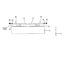
図1は本発明の物理量センサーの第1実施形態を示す構成概略図である。図2は図1におけるA−A断面拡大図である。なお各図では、説明の便宜上、互いに直交する3つの軸として、X軸、Y軸、Z軸を図示している。また以下では、X軸(第1軸)に平行な方向をX軸方向、Y軸(第2軸)に平行な方向をY軸方向、Z軸(第3軸)に平行な方向をZ軸方向という。
Embodiments of a physical quantity sensor and an electronic apparatus according to the present invention will be described below in detail with reference to the accompanying drawings.
FIG. 1 is a schematic configuration diagram showing a first embodiment of a physical quantity sensor of the present invention. FIG. 2 is an AA cross-sectional enlarged view in FIG. In each figure, for convenience of explanation, an X axis, a Y axis, and a Z axis are illustrated as three axes orthogonal to each other. In the following, the direction parallel to the X axis (first axis) is the X axis direction, the direction parallel to the Y axis (second axis) is the Y axis direction, and the direction parallel to the Z axis (third axis) is the Z axis. It is called direction.
本発明の物理量センサー10は、振動系構造体12上に、第1及び第2変位部20,30と、回転軸22,32と、支持部40と、固定部50と、支持部40と固定部50を接続するバネ部60と、駆動部70と、を主な基本構成として形成されている。なお本実施形態の物理量センサー10は、X軸、Y軸又はZ軸のいずれか1軸まわりの角速度を検出可能なセンサーであり、以下、一例として、X軸方向に沿って振動可能とし、Y軸まわりに作用する回転を検出可能な角速度センサーの構成について説明する。
The
振動系構造体12は、シリコンを主材料として構成されていて、シリコン基板(シリコンウエハ)上に薄膜形成技術(例えば、エピタキシャル成長技術、化学気相成長技術等の堆積技術)や各種加工技術(例えばドライエッチング、ウェットエッチング等のエッチング技術)を用いて所望の外形形状に加工することにより、前述した各部が一体的に形成されている。或いは、シリコン基板とガラス基板を張り合わせた後に、シリコン基板のみを所望の外形形状に加工することで、前述の各部を形成することもできる。振動系構造体12の主材料をシリコンとすることにより、優れた振動特性を実現できるとともに、優れた耐久性を発揮することができる。またシリコン半導体デバイス作製に用いられる微細な加工技術の適用が可能となり、物理量センサー10の小型化を図ることができる。
The
第1及び第2変位部20,30は、Z軸を法線とするXY平面視において、矩形の板状に形成され、XY平面の空間平面をZ軸方向に変位する変位板21,31を備えている。変位板21,31は、回転軸22,32で支持部40に連結されている。回転軸22,32は、図2に示すように各変位板21,31の重心からずれた位置に形成している。回転軸22,32は共に、振動方向であるX軸方向に延在して設けられている。回転軸22,32は、外力が加わったときにその軸まわりにねじり変形させ変位板21,31をZ方向に回転させる。
The first and
このような構成により、第1及び第2変位部20,30は、回転軸22,32に対し重力(Z軸方向の外力)による回転方向が互いに逆方向に回転するように取り付けている。換言すると、回転軸22の変位板21の重心からのずれの方向と、回転軸32の変位板31の重心からのずれの方向とは、互いに反対方向であるとも言える。
With such a configuration, the first and
支持部40は、第1及び第2変位部20,30を支持するフレームである。第1実施形態の支持部40は、第1及び第2変位部20,30の外周を囲む開口42を備え、変位板21,31の揺動側(自由端側)が互いに内側を向くように回転軸22,32を介して支持している。なお、支持部40の形状はフレーム形状に限定されずに、他の形状でも適用可能である。
The
固定部50は、支持部40の外側に複数設けられている。本実施形態ではZ軸を法線とする平面視にて、矩形状に配置した固定部50a,50b,50c,50dで囲まれる領域の中に支持部40を設けている。
A plurality of fixing
バネ部60は、支持部40と固定部50とを連結している。第1実施形態のバネ部60は、第1及び第2バネ部62,64から構成されている。第1バネ部62は、一対のバネ部62a,62bから構成されており、各バネ部62a,62bはY軸方向に往復しながらX軸方向に延在する形状をなしている。またバネ部62a,62bは、Z軸を法線とする平面視にて、支持部40の中心と交わるY軸に対して対称的に設けられている。各バネ部62a,62bをこのような形状とすることにより、第1バネ部62をY軸方向及びZ軸方向への変形を抑制しつつ、振動方向であるX軸方向にスムーズに伸縮させることができる。また、第2バネ部64の構成は、支持部40の中心と交わるX軸に対して、第1バネ部62と対称的に設けられ、一対のバネ部64a,64bから構成されている。各バネ部64a,64bをこのような形状とすることにより、第2バネ部64をY軸方向及びZ軸方向への変形を抑制しつつ、振動方向であるX軸方向にスムーズに伸縮させることができる。
The
駆動部70は、支持部40をX軸方向に所定の周波数で振動させる機能を備えている。すなわち駆動部70は、支持部40を+X軸方向に変位させる状態と、−X軸方向に変位させる状態とを繰り返すように振動させている。駆動部70a,70bは、図示しない駆動電極と固定電極から構成され、第1及び第2変位部20,30のそれぞれに形成しているが、支持部40をX方向に振動させることができる構成であれば、いずれか一方の変位部だけでも良い。固定電極は駆動電極を介してX軸方向に対向配置された櫛歯状の一対の電極片を有している。このような構成の駆動部70は、図示しない電源によって、電極片に電圧を印加することにより、各駆動電極と各電極片との間に静電力を発生させ、バネ部60を伸縮させつつ、支持部40を所定の周波数でX軸方向に振動させている。なお駆動部70は、静電駆動方式、圧電駆動方式、又は磁場のローレンツ力を利用した電磁駆動方式等を適用することができる。
The
図2に示す基板74は、振動系構造体12を支持するものである。基板74は、シリコンを主材料として構成されているが、シリコンに限定されず、例えば、水晶や、各種ガラスであってもよい。基板74は板状であって、上面に固定部50を接合させている。これにより振動系構造体12を基板74上に固定・支持させることができる。なお基板74と振動系構造体12の隙間は、外力によって変位する第1及び第2変位部20,30が接触することがない距離に設定している。基板74と振動系構造体12の接合方法は、特に限定されず、直接接合や、陽極接合等の各種接合方法を用いて接合することができる。なお、固定部50は、基板74上に限定されず、基板74以外の部材(例えば、パッケージなど)に設けても良い。また基板74の上面であって、第1及び第2変位部20,30と対向する箇所には、下部電極(固定電極部)76を設けている。第1及び第2変位部20,30と、基板74に固定された第1及び第2変位部20,30とZ軸方向に離間して対向配置された下部電極76により、トランスデューサーが形成される。
A
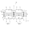
図3は本発明の物理量センサーの第2実施形態を示す構成概略図である。図示のように第2実施形態の物理量センサー100は、振動系構造体120上に2つの振動体と、各振動体に設けられた4つの変位部を備えている。具体的に物理量センサー100は、センサーの振動方向に沿って第1及び第2変位部20,30を有する第1振動体14と、第3及び第4変位部80,90を有する第2振動体16から構成されている。なお、振動系構造体120は、シリコンを主材料として構成されていて、シリコン基板(シリコンウエハ)上に薄膜形成技術や各種加工技術を用いて所望の外形形状に加工することにより、各部が一体的に形成されている。第1及び第2変位部20,30の構成は、第1実施形態の構成と同様であり、その詳細な説明を省略する。また第3及び第4変位部80,90の基本構成は、第1及び第2変位部20,30と同様である。但し、第1及び第2の変位部20,30と第3及び第4変位部80,90の間には、第3バネ部(連結バネ)66を形成している。第3バネ部66は、一対のバネ部66a,66bから構成されており、各バネ部66a,66bはY軸方向に往復しながらX軸方向に延在する形状をなしている。またバネ部66a,66bは、Z軸を法線とするXY平面視にて、第1支持部44と第2支持部46の中心と交わるX軸に対して対称的に設けられている。各バネ部66a,66bをこのような形状とすることにより、第1バネ部62をY軸方向及びZ軸方向への変形を抑制しつつ、X軸方向にスムーズに伸縮させることができる。
FIG. 3 is a schematic configuration diagram showing a second embodiment of the physical quantity sensor of the present invention. As illustrated, the
また第2実施形態の物理量センサー100の駆動部72は、第1実施形態の駆動部70と基本構成は同じである。しかし、第1及び第2変位部20,30の駆動部72a,72bと、第3及び第4変位部80,90の駆動部72c,72dに対して、位相が180度ずれた交番電圧を印加することにより、各駆動電極と各電極片との間にそれぞれ静電力を発生させ、第1〜第3バネ部62,64,66をX軸方向に伸縮させつつ、第1及び第2変位部20,30と、第3及び第4変位部80,90が互いに逆位相でかつ所定の周波数でX軸方向に振動させている。なお、駆動部72a,72bは、どちらか一方のみ形成されていれば良い。駆動部72c,72dについても同様である。
The
なお、第2実施形態の物理量センサー100は、第1〜第4変位部20,30,80,90のそれぞれに対向する下部電極76との間に発生する静電容量をそれぞれC1〜C4とした場合、その出力を、(C1+C2)−(C3+C4)となるように設定している。
In the
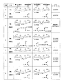
次に上記構成による本発明の物理量センサー10,100の作用について以下説明する。図4は物理量センサーの作用の説明図である。なお、図4では変位板に加わる力の状態によりA〜Gに場合分けして表記している。
Next, the operation of the
まず、物理量センサーに対する入力がゼロの場合(状態A)、第1〜第4変位部20,30,80,90の回転軸22,32,82,92の延びる方向と、振動方向が同じため、変位板の自重による傾き以外に第1〜第4変位部20,30,80,90は変動しない。従ってトランスデューサーの容量変化は起こらないため出力はゼロとなる。
First, when the input to the physical quantity sensor is zero (state A), the direction in which the
次に物理量センサーに対するX軸まわりの角速度が入力された場合(状態B)、第1〜第4変位部20,30,80,90の回転軸22,32,82,92の軸方向は、振動方向と同じ方向に形成されているため、コリオリ力は発生しない。従って、トランスデューサーの容量変化は起こらないため出力はゼロとなる。
Next, when the angular velocity around the X axis with respect to the physical quantity sensor is input (state B), the axial directions of the
次に物理量センサーに対するY軸まわりの角速度が入力された場合(状態C)について説明する。ここで第1振動体14の第1及び第2変位部20,30が−X軸方向へ振動し、第2の振動体16の第3及び第4変位部80,90が+X軸方向へ振動し、Y軸まわりに角速度が入力されたと仮定する。一般にコリオリ力Fcoriは、
![]()
![]()
第1及び第2変位部20,30では、−X軸方向へ振動させつつ、Y軸まわりの角速度Ωyが加わると、−Z軸方向のコリオリ力が作用して、変位板21,31が−Z軸方向に回転し、これにより、変位板21,31と下部電極76の間の静電容量C1,C2が変化する。また第3及び第4変位部80,90では、+X軸方向へ振動させつつ、Y軸まわりの角速度Ωyが加わると、+Z軸方向のコリオリ力が作用して、変位板21,31が+Z軸方向に回転し、これにより変位板81,91と下部電極76の間の静電容量C3,C4が変化する。このように第1及び第2変位部20,30と第3及び第4変位部80,90では、コリオリ力の向きが逆方向となり、第1〜第4変位部20,30,80,90の静電容量C1〜C4の出力は、(C1+C2)−(C3+C4)により、Y軸まわりの角速度に応じた容量変化を検出することができる。
In the first and
次に物理量センサーに対するZ軸まわりの角速度が入力された場合(状態D)について説明する。ここで第1振動体14の第1及び第2変位部20,30が−X軸方向へ振動し、第2振動体16の第3及び第4変位部80,90が+X軸方向へ振動し、Z軸まわりに角速度が入力されたと仮定する。
Next, the case where the angular velocity around the Z axis with respect to the physical quantity sensor is input (state D) will be described. Here, the first and
第1及び第2変位部20,30では、−X軸方向へ振動させつつ、Z軸まわりの角速度Ωzが加わると、+Y軸方向のコリオリ力が作用する。このとき第1及び第2変位部20,30の回転軸22,32は、各変位板21,31の重心からずれた位置に形成し、重心からのずれの方向が互いに反対に形成している。このため、変位板21は−Z軸方向へ押下げられ、変位板31は+z軸方向へ押し上げられる。これにより、変位板21,31と下部電極76の間の静電容量C1,C2が変化する。
In the first and
第3及び第4変位部80,90では、+X軸方向へ振動させつつ、Z軸まわりの角速度Ωzが加わると、−Y軸方向のコリオリ力が作用する。このとき第3及び第4変位部80,90の回転軸82,92は、各変位板81,91の重心からずれた位置に形成し、重心からのずれの方向が互いに反対に形成している。このため、変位板81は+Z軸方向へ押し上げられ、変位板91は−Z軸方向へ押し下げられる。これにより変位板81,91と下部電極76の間の静電容量C3,C4が変化する。
In the third and
この結果、第1〜第4変位部20,30,80,90の静電容量C1〜C4の出力は、C1−C4=0及びC2−C3=0で、(C1+C2)−(C3+C4)=(C1−C4)−(C2−C3)=0となり、Z軸方向に作用するコリオリ力は検出されない。
As a result, the outputs of the capacitances C1 to C4 of the first to
次に物理量センサーに対するX軸方向の加速度が入力された場合(状態E)、第1〜第4変位部20,30,80,90の回転軸22,32,82,92の軸方向は、X軸方向の加速度と同じ方向に形成されているため、変位部は変位しない。従って、トランスデューサーの容量変化は起こらないため出力はゼロとなる。
Next, when acceleration in the X-axis direction with respect to the physical quantity sensor is input (state E), the axial directions of the
次に物理量センサーに対する+Y軸方向の加速度が入力された場合(状態F)、第1及び第2変位部20,30では、−X軸方向へ振動させつつ、+Y軸方向の加速度が加わる。第1及び第2変位部20,30の回転軸22,32は、各変位板21,31の重心からずれた位置に形成し、重心からのずれの方向が互いに反対に形成している。このため、変位板21は+Z軸方向へ押し上げられ、変位板31は−Z軸方向へ押し下げられる。これにより、変位板21,31と下部電極76の間の静電容量C1,C2が変化する。
Next, when acceleration in the + Y-axis direction with respect to the physical quantity sensor is input (state F), the first and
また第3及び第4変位部80,90では、+X軸方向へ振動させつつ、+Y軸方向の加速度が加わる。第3及び第4変位部80,90の回転軸82,92は、各変位板81,91の重心からずれた位置に形成し、重心からのずれの方向が互いに反対に形成している。このため、変位板81は+Z軸方向へ押し上げられ、変位板91は−Z軸方向へ押し下げられる。これにより変位板81,91と下部電極76の間の静電容量C3,C4が変化する。
Further, in the third and
この結果、第1〜第4変位部20,30,80,90の静電容量C1〜C4の出力はC1−C3=0、C2−C4=0となり、Y軸方向に作用する加速度は検出されない。なお物理量センサーに−Y軸方向の加速度が入力された場合でも、第1〜第4変位部20,30,80,90の静電容量C1〜C4の出力は、C1−C3=0及びC2−C4=0で、(C1+C2)−(C3+C4)=(C1−C3)+(C2−C4)=0となり、Y軸方向に作用する加速度は検出されない。
As a result, the outputs of the capacitances C1 to C4 of the first to
最後に、物理量センサーに対する+Z軸方向の加速度が入力された場合(状態G)、第1及び第2変位部20,30では、−X軸方向へ振動させつつ、+Z軸方向の加速度が加わることにより、変位板21と変位板31が−Z軸方向に回転し、これにより変位板21,31と下部電極76の間の静電容量C1,C2が変化する。また第3及び第4変位部80,90では、+X軸方向へ振動させつつ、+Z軸方向の加速度が加わることにより、変位板81と変位板91が−Z軸方向に回転し、これにより変位板81,91と下部電極76の間の静電容量C3,C4が変化する。この結果、第1〜第4変位部20,30,80,90の静電容量C1〜C4は全て同じ値で、出力はC1+C2=C3+C4となり、+Z軸方向に作用する加速度は検出されない。なお物理量センサーに−Z軸方向の加速度が入力された場合でも、第1〜第4変位部20,30,80,90の静電容量C1〜C4は全て同じ値で、出力はC1+C2=C3+C4となり、Z軸方向に作用する加速度は検出されない。
Finally, when acceleration in the + Z-axis direction for the physical quantity sensor is input (state G), the first and
なお、回転軸と同じ軸方向を除く角速度及び加速度は、第2実施形態に係る物理量センサー100で適用することができるが、Z軸方向の加速度を除く場合であれば、第1実施形態に係る物理量センサーであっても適用することができる。
The angular velocity and acceleration except for the same axial direction as the rotation axis can be applied in the
このような物理量センサーによれば、検出軸まわりの角速度のみを検出して、ノイズとなる検出軸以外の他軸の角速度が検出されない。従って物理量検出を高精度に行うことができる。 According to such a physical quantity sensor, only the angular velocity around the detection axis is detected, and the angular velocity of other axes other than the detection axis that causes noise is not detected. Therefore, physical quantity detection can be performed with high accuracy.
図5は本発明の物理量センサーの第3実施形態を示す構成概略図である。図示のように第3実施形態の物理量センサー100aは、第1及び第2変位部20a,30aの回転軸22a,32aが互いに近接する側であって、変位板21a,31aの揺動側(自由端側)が、外側を向くように第1支持部44に固定している。また第3及び第4変位部80a,90aの回転軸82a,92aが互いに近接する側であって、変位板81a,91aの揺動側(自由端側)が、外側を向くように第2支持部46に固定している。このとき第1〜第4変位部20a,30a,80a,90aの回転軸22a,32a,82a,92aの各々は、前記第1〜第4変位部20a,30a,80a,90aの各々の重心からずれて設けられている。また第1変位部20aの回転軸22aと第2変位部30aの回転軸32aとは、重心からのずれの方向が互いに反対となり、且つ、第3変位部80aの回転軸82aと第4変位部90aの回転軸92aとは、重心からのずれの方向が互いに反対となるように配置させている。その他の構成は第2実施形態の物理量センサー100の構成と同一であり、同一の符号を付して詳細な説明を省略する。
FIG. 5 is a schematic configuration diagram showing a third embodiment of the physical quantity sensor of the present invention. As shown in the figure, the
このような構成の第3実施形態の物理量センサー100aによっても、物理量センサーを角速度センサーとして用いた場合に、検出軸まわりの角速度のみを検出して、ノイズとなる検出軸以外の他軸の角速度が検出されない。従って物理量検出を高精度に行うことができる。また第1及び第2変位部20a,30aの回転軸22a,32aが第1支持部44の内側に、第3及び第4変位部80a,90aの回転軸82a,92aが第2支持部46の内側にそれぞれ取り付けられた構成となり、変位板同士が接触して破損することのない形態とすることができる。
Also in the
図6は本発明の物理量センサーの第4実施形態を示す構成概略図である。図示のように第4実施形態の物理量センサー100bは、第1〜第4変位部20b,30b,80b,90bを、Z軸を法線とするXY平面視にて、X軸方向に並べて配置している。このとき、第1〜第4変位部20b,30b,80b,90bの回転軸22b,32b,82b,92bの各々は、前記第1〜第4変位部20b,30b,80b,90bの各々の重心からずれて設けられている。また第1変位部20bの回転軸22bと第2変位部30bの回転軸32bとは、重心からのずれの方向が互いに反対となり、且つ、第3変位部80bの回転軸82bと第4変位部90bの回転軸92bとは、重心からのずれの方向が互いに反対となるように配置させている。その他の構成は第2実施形態の物理量センサー100の構成と同一であり、同一の符号を付して詳細な説明を省略する。
FIG. 6 is a schematic configuration diagram showing a fourth embodiment of the physical quantity sensor of the present invention. As illustrated, the
このような構成の第4実施形態の物理量センサー100bによっても、物理量センサーを角速度センサーとして用いた場合に、検出軸まわりの角速度のみを検出して、ノイズとなる検出軸以外の他軸の角速度が検出されない。従って物理量検出を高精度に行うことができる。
Also in the
図7は本発明の物理量センサーの第5実施形態を示す構成概略図である。図示のように第5実施形態の物理量センサー100cは、Z軸を法線とするXY平面視にて、第1及び第2支持部44a,46aを略H型形状に形成し、±Y軸方向の2つの凹部に第1〜第4変位部20c,30c,80c,90cを取り付けている。また駆動部70a,70bは、第1及び第2支持部44a,46aにそれぞれ取り付けた構成としている。このとき、第1〜第4変位部20c,30c,80c,90cの回転軸22c,32c,82c,92cの各々は、前記第1〜第4変位部20c,30c,80c,90cの各々の重心からずれて設けられている。また第1変位部20cの回転軸22cと第2変位部30cの回転軸32cとは、重心からのずれの方向が互いに反対となり、且つ、第3変位部80cの回転軸82cと第4変位部90cの回転軸92cとは、重心からのずれの方向が互いに反対となるように配置させている。その他の構成は第2実施形態の物理量センサー100の構成と同一であり、同一の符号を付して詳細な説明を省略する。
FIG. 7 is a schematic configuration diagram showing a fifth embodiment of the physical quantity sensor of the present invention. As shown in the drawing, the
このような構成の第5実施形態の物理量センサー100cによっても、物理量センサーを角速度センサーとして用いた場合に、検出軸まわりの角速度のみを検出して、ノイズとなる検出軸以外の他軸の角速度が検出されない。従って物理量検出を高精度に行うことができる。また第1〜第4変位部20c,30c,80c,90cが第1及び第2支持部44a,46aの外側に取り付けられた構成となり、変位板を支持部の枠内に配置した構成の物理量センサーよりも、配線の寄生容量を小さくすることができる。
Also in the
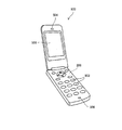
図8は本発明の物理量センサーを備える電子機器を適用した携帯電話機の説明図である。図示のように携帯電話機500は、複数の操作ボタン502、受話口504、および送信口506を備え、操作ボタン502と受話器504との間には、表示部508が配置されている。このような携帯電話機500には角速度検出手段(ジャイロセンサー)として機能する物理量センサー10,100,100a,100b,100cが内蔵されている。
FIG. 8 is an explanatory diagram of a mobile phone to which an electronic device including the physical quantity sensor of the present invention is applied. As shown in the figure, the
10,100,100a,100b,100c………物理量センサー、12,120………振動系構造体、14………第1振動体、16………第2振動体、20,20a,20b,20c………第1変位部、21,21a,21b,21c………変位板、22,22a,22b,22c………回転軸、30,30a,30b,30c………第2変位部、31,31a,31b,31c………変位板、32,32a,32b,32c………回転軸、40………支持部、42………開口、44,44a………第1支持部、46,46a………第2支持部、50………固定部、60………バネ部、62………第1バネ部、64………第2バネ部、66………第3バネ部(連結バネ)、70………駆動部、72………駆動部、74………基板、76………下部電極、80,80a,80b,80c………第3変位部、90,90a,90b,90c………第4変位部、500………携帯電話機、502………操作ボタン、504………受話口、506………送信口、508………表示部。 10, 100, 100a, 100b, 100c ......... physical quantity sensor, 12, 120 ......... vibrating system structure, 14 ......... first vibrating body, 16 ......... second vibrating body, 20, 20a, 20b, 20c ......... first displacement portion, 21, 21a, 21b, 21c ......... displacement plate, 22, 22a, 22b, 22c ......... rotation shaft, 30, 30a, 30b, 30c ......... second displacement portion, 31, 31 a, 31 b, 31 c ............ displacement plate, 32, 32 a, 32 b, 32 c ...... Rotation shaft, 40 ...... support part, 42 ...... opening, 44, 44 a ...... first support part, 46, 46a ......... second support portion, 50 ......... fixed portion, 60 ......... spring portion, 62 ......... first spring portion, 64 ......... second spring portion, 66 ......... third spring Part (connection spring), 70... Drive part, 72... Drive part, 74. ... Lower electrode, 80, 80a, 80b, 80c ......... Third displacement part, 90, 90a, 90b, 90c ... ... Fourth displacement part, 500 ... ... Mobile phone, 502 ... ... Operation buttons, 504 ... ...... Earpiece, 506... Transmitter, 508 ... Display section.
Claims (8)
前記基板上の空間平面に配置され、回転軸を有した第1変位部及び第2変位部と、
前記基板の前記第1変位部及び第2変位部の各々に対向する位置に設けられた固定電極部と、
前記第1変位部及び第2変位部の各々の前記回転軸を支持する支持部と、
バネ部を介して前記支持部を支持する固定部と、
前記支持部を振動方向に振動させる駆動部と、を備え、
前記第1変位部及び第2変位部は、前記回転軸を軸として前記空間平面に対して垂直方向に変位可能であり、
前記回転軸の各々は、前記第1変位部又は第2変位部の重心からずれて設けられ、
前記第1変位部の前記回転軸と前記第2変位部の前記回転軸とは、前記重心からのずれの方向が互いに反対であることを特徴とする物理量センサー。 A substrate,
A first displacement portion and a second displacement portion which are arranged in a spatial plane on the substrate and have a rotation axis;
A fixed electrode portion provided at a position facing each of the first displacement portion and the second displacement portion of the substrate;
A support portion for supporting the rotation shaft of each of the first displacement portion and the second displacement portion;
A fixing part that supports the support part via a spring part;
A drive unit that vibrates the support unit in a vibration direction,
The first displacement portion and the second displacement portion can be displaced in a direction perpendicular to the space plane with the rotation axis as an axis,
Each of the rotation shafts is provided to be shifted from the center of gravity of the first displacement portion or the second displacement portion,
The physical quantity sensor, wherein the rotation axis of the first displacement part and the rotation axis of the second displacement part are opposite to each other in the direction of deviation from the center of gravity.
前記基板上の空間平面に配置された第1振動体及び第2振動体と、を有し、
前記第1振動体は、回転軸を有した第1変位部及び第2変位部と、前記第1変位部及び前記第2変位部の前記回転軸の各々を支持する第1支持部と、を備え、
前記第2振動体は、回転軸を有した第3変位部及び第4変位部と、前記第3変位部及び前記第4変位部の前記回転軸の各々を支持する第2支持部と、を備え、
前記基板の前記第1〜第4変位部の各々に対向する位置に設けられた固定電極部と、
バネ部を介して前記第1支持部及び第2支持部の各々を支持する固定部と、
前記第1支持部及び第2支持部の各々を振動させる駆動部と、を備え、
前記第1振動体及び前記第2振動体は、互いに反対方向に振動し、
前記第1〜第4変位部は、前記回転軸を軸として前記空間平面に対し垂直方向に変位可能であり、
前記回転軸の各々は、前記第1〜第4変位部の各々の重心からずれて設けられ、
前記第1変位部の前記回転軸と前記第2変位部の前記回転軸とは、前記重心からのずれの方向が互いに反対であり、
且つ、前記第3変位部の前記回転軸と前記第4変位部の前記回転軸とは、前記重心からのずれの方向が互いに反対であることを特徴とする物理量センサー。 A substrate,
A first vibrator and a second vibrator arranged in a space plane on the substrate;
The first vibrating body includes a first displacement portion and a second displacement portion having a rotation axis, and a first support portion that supports each of the rotation shafts of the first displacement portion and the second displacement portion. Prepared,
The second vibrating body includes a third displacement portion and a fourth displacement portion having a rotation axis, and a second support portion that supports each of the rotation shafts of the third displacement portion and the fourth displacement portion. Prepared,
A fixed electrode portion provided at a position facing each of the first to fourth displacement portions of the substrate;
A fixing part that supports each of the first support part and the second support part via a spring part;
A drive unit that vibrates each of the first support unit and the second support unit,
The first vibrating body and the second vibrating body vibrate in opposite directions;
The first to fourth displacement portions can be displaced in a direction perpendicular to the space plane with the rotation axis as an axis,
Each of the rotation shafts is provided to be shifted from the center of gravity of each of the first to fourth displacement portions,
The rotational axis of the first displacement part and the rotational axis of the second displacement part are opposite to each other in the direction of deviation from the center of gravity.
The physical quantity sensor is characterized in that the rotational axis of the third displacement part and the rotational axis of the fourth displacement part are opposite to each other in the direction of deviation from the center of gravity.
前記第2変位部とこれに対向する前記固定電極部との間の静電容量をC2とし、
前記第3変位部とこれに対向する前記固定電極部との間の静電容量をC3とし、
前記第4変位部とこれに対向する前記固定電極部との間の静電容量をC4としたときに、
前記物理量センサーの出力値を
(C1+C2)−(C3+C4)
とすることを特徴とする請求項4又は5に記載の物理量センサー。 The capacitance between the first displacement part and the fixed electrode part facing the first displacement part is C1,
The capacitance between the second displacement part and the fixed electrode part facing the second displacement part is C2,
The capacitance between the third displacement part and the fixed electrode part facing the third displacement part is C3,
When the capacitance between the fourth displacement portion and the fixed electrode portion facing the fourth displacement portion is C4,
The output value of the physical quantity sensor is (C1 + C2) − (C3 + C4)
The physical quantity sensor according to claim 4 or 5, wherein:
Priority Applications (6)
| Application Number | Priority Date | Filing Date | Title |
|---|---|---|---|
| JP2011033665A JP2012173055A (en) | 2011-02-18 | 2011-02-18 | Physical quantity sensor and electronic apparatus |
| TW101104576A TWI476372B (en) | 2011-02-18 | 2012-02-13 | Physical quantity sensor and electronic device |
| US13/398,010 US9273962B2 (en) | 2011-02-18 | 2012-02-16 | Physical quantity sensor and electronic device |
| KR1020120015716A KR101365096B1 (en) | 2011-02-18 | 2012-02-16 | Physical quantity sensor and electronic apparatus |
| EP12155738.3A EP2489981A3 (en) | 2011-02-18 | 2012-02-16 | Angular velocity sensor and electronic device |
| CN201210038089.1A CN102645550B (en) | 2011-02-18 | 2012-02-17 | Physical quantity transducer and electronic equipment |
Applications Claiming Priority (1)
| Application Number | Priority Date | Filing Date | Title |
|---|---|---|---|
| JP2011033665A JP2012173055A (en) | 2011-02-18 | 2011-02-18 | Physical quantity sensor and electronic apparatus |
Related Child Applications (1)
| Application Number | Title | Priority Date | Filing Date |
|---|---|---|---|
| JP2015210563A Division JP6146592B2 (en) | 2015-10-27 | 2015-10-27 | Physical quantity sensor, electronic equipment |
Publications (2)
| Publication Number | Publication Date |
|---|---|
| JP2012173055A true JP2012173055A (en) | 2012-09-10 |
| JP2012173055A5 JP2012173055A5 (en) | 2014-04-03 |
Family
ID=45571472
Family Applications (1)
| Application Number | Title | Priority Date | Filing Date |
|---|---|---|---|
| JP2011033665A Pending JP2012173055A (en) | 2011-02-18 | 2011-02-18 | Physical quantity sensor and electronic apparatus |
Country Status (6)
| Country | Link |
|---|---|
| US (1) | US9273962B2 (en) |
| EP (1) | EP2489981A3 (en) |
| JP (1) | JP2012173055A (en) |
| KR (1) | KR101365096B1 (en) |
| CN (1) | CN102645550B (en) |
| TW (1) | TWI476372B (en) |
Cited By (1)
| Publication number | Priority date | Publication date | Assignee | Title |
|---|---|---|---|---|
| US9389078B2 (en) | 2012-04-10 | 2016-07-12 | Seiko Epson Corporation | Gyro sensor and electronic apparatus |
Families Citing this family (9)
| Publication number | Priority date | Publication date | Assignee | Title |
|---|---|---|---|---|
| IT1392741B1 (en) | 2008-12-23 | 2012-03-16 | St Microelectronics Rousset | MICROELETTROMECHANICAL GYROSCOPE WITH IMPROVED REJECTION OF ACCELERATION DISORDERS |
| IT1394007B1 (en) | 2009-05-11 | 2012-05-17 | St Microelectronics Rousset | MICROELETTROMECANICAL STRUCTURE WITH IMPROVED REJECTION OF ACCELERATION DISORDERS |
| ITTO20091042A1 (en) | 2009-12-24 | 2011-06-25 | St Microelectronics Srl | MICROELETTROMECHANICAL INTEGRATED GYROSCOPE WITH IMPROVED DRIVE STRUCTURE |
| ITTO20110806A1 (en) | 2011-09-12 | 2013-03-13 | St Microelectronics Srl | MICROELETTROMECANICAL DEVICE INTEGRATING A GYROSCOPE AND AN ACCELEROMETER |
| JP5979344B2 (en) * | 2012-01-30 | 2016-08-24 | セイコーエプソン株式会社 | Physical quantity sensor and electronic equipment |
| US9404747B2 (en) | 2013-10-30 | 2016-08-02 | Stmicroelectroncs S.R.L. | Microelectromechanical gyroscope with compensation of quadrature error drift |
| JP2015184009A (en) * | 2014-03-20 | 2015-10-22 | セイコーエプソン株式会社 | Vibration element, electronic apparatus, and mobile entity |
| JP6930396B2 (en) * | 2017-11-28 | 2021-09-01 | セイコーエプソン株式会社 | Physical quantity sensors, physical quantity sensor devices, composite sensor devices, inertial measurement units, portable electronic devices and mobile objects |
| JP2020085744A (en) | 2018-11-28 | 2020-06-04 | セイコーエプソン株式会社 | Acceleration sensor, electronic apparatus, and mobile body |
Citations (4)
| Publication number | Priority date | Publication date | Assignee | Title |
|---|---|---|---|---|
| JP2003130648A (en) * | 2002-08-08 | 2003-05-08 | Kazuhiro Okada | Angular velocity sensor |
| JP2008514968A (en) * | 2004-09-27 | 2008-05-08 | コンティ テミック マイクロエレクトロニック ゲゼルシャフト ミット ベシュレンクテル ハフツング | Rotational speed sensor |
| JP2009529666A (en) * | 2006-03-10 | 2009-08-20 | コンティネンタル・テーベス・アクチエンゲゼルシヤフト・ウント・コンパニー・オッフェネ・ハンデルスゲゼルシヤフト | Rotational speed sensor with connecting rod |
| JP2010276367A (en) * | 2009-05-26 | 2010-12-09 | Denso Corp | Acceleration/angular velocity sensor |
Family Cites Families (12)
| Publication number | Priority date | Publication date | Assignee | Title |
|---|---|---|---|---|
| US5646346A (en) | 1994-11-10 | 1997-07-08 | Okada; Kazuhiro | Multi-axial angular velocity sensor |
| JPH073337A (en) * | 1993-06-21 | 1995-01-06 | Nippon Steel Corp | Device for cooling steel strip |
| JPH07190782A (en) * | 1993-12-27 | 1995-07-28 | Nikon Corp | Vibrational angular velocity meter |
| DE4414237A1 (en) | 1994-04-23 | 1995-10-26 | Bosch Gmbh Robert | Micromechanical vibrator of an oscillation gyrometer |
| DE19541388A1 (en) * | 1995-11-07 | 1997-05-15 | Telefunken Microelectron | Micromechanical acceleration sensor |
| JP3512004B2 (en) | 2000-12-20 | 2004-03-29 | トヨタ自動車株式会社 | Physical quantity detector |
| DE10108197A1 (en) | 2001-02-21 | 2002-09-12 | Bosch Gmbh Robert | Yaw rate sensor |
| US6928872B2 (en) * | 2001-04-27 | 2005-08-16 | Stmicroelectronics S.R.L. | Integrated gyroscope of semiconductor material with at least one sensitive axis in the sensor plane |
| JP2008058259A (en) * | 2006-09-04 | 2008-03-13 | Sony Corp | Inertial sensor and manufacturing method therefor |
| US7578190B2 (en) * | 2007-08-03 | 2009-08-25 | Freescale Semiconductor, Inc. | Symmetrical differential capacitive sensor and method of making same |
| US8042396B2 (en) | 2007-09-11 | 2011-10-25 | Stmicroelectronics S.R.L. | Microelectromechanical sensor with improved mechanical decoupling of sensing and driving modes |
| TW201004748A (en) * | 2008-07-22 | 2010-02-01 | Eclatorq Technology Co Ltd | Tool having the function of measuring angle |
-
2011
- 2011-02-18 JP JP2011033665A patent/JP2012173055A/en active Pending
-
2012
- 2012-02-13 TW TW101104576A patent/TWI476372B/en not_active IP Right Cessation
- 2012-02-16 KR KR1020120015716A patent/KR101365096B1/en active IP Right Grant
- 2012-02-16 EP EP12155738.3A patent/EP2489981A3/en not_active Ceased
- 2012-02-16 US US13/398,010 patent/US9273962B2/en not_active Expired - Fee Related
- 2012-02-17 CN CN201210038089.1A patent/CN102645550B/en not_active Expired - Fee Related
Patent Citations (4)
| Publication number | Priority date | Publication date | Assignee | Title |
|---|---|---|---|---|
| JP2003130648A (en) * | 2002-08-08 | 2003-05-08 | Kazuhiro Okada | Angular velocity sensor |
| JP2008514968A (en) * | 2004-09-27 | 2008-05-08 | コンティ テミック マイクロエレクトロニック ゲゼルシャフト ミット ベシュレンクテル ハフツング | Rotational speed sensor |
| JP2009529666A (en) * | 2006-03-10 | 2009-08-20 | コンティネンタル・テーベス・アクチエンゲゼルシヤフト・ウント・コンパニー・オッフェネ・ハンデルスゲゼルシヤフト | Rotational speed sensor with connecting rod |
| JP2010276367A (en) * | 2009-05-26 | 2010-12-09 | Denso Corp | Acceleration/angular velocity sensor |
Cited By (1)
| Publication number | Priority date | Publication date | Assignee | Title |
|---|---|---|---|---|
| US9389078B2 (en) | 2012-04-10 | 2016-07-12 | Seiko Epson Corporation | Gyro sensor and electronic apparatus |
Also Published As
| Publication number | Publication date |
|---|---|
| CN102645550A (en) | 2012-08-22 |
| EP2489981A3 (en) | 2014-07-02 |
| US20120210789A1 (en) | 2012-08-23 |
| EP2489981A2 (en) | 2012-08-22 |
| US9273962B2 (en) | 2016-03-01 |
| TWI476372B (en) | 2015-03-11 |
| KR20120095310A (en) | 2012-08-28 |
| TW201235638A (en) | 2012-09-01 |
| CN102645550B (en) | 2016-04-13 |
| KR101365096B1 (en) | 2014-02-19 |
Similar Documents
| Publication | Publication Date | Title |
|---|---|---|
| KR101365096B1 (en) | Physical quantity sensor and electronic apparatus | |
| JP5822177B2 (en) | Gyro sensor, electronic equipment | |
| US8408060B2 (en) | Piezoelectric transducers and inertial sensors using piezoelectric transducers | |
| JP5554930B2 (en) | Capacitive bulk acoustic wave disk gyroscope with self-calibration | |
| JP5716827B2 (en) | Vibrator and vibratory gyro | |
| JP6300395B2 (en) | Angular velocity sensor with quadrature error compensation | |
| JP4702942B2 (en) | Vibrating gyro element and vibrating gyro | |
| KR20110011625A (en) | Vibrating micro-mechanical sensor of angular velocity | |
| JP2013156260A (en) | X-axis ring gyro transducer having high resistance against vibration | |
| WO2007145113A1 (en) | Inertial sensor | |
| KR20060096060A (en) | Z-axis angular rate sensor | |
| JP2013092525A (en) | Inertial sensor with off-axis spring system | |
| JP2008039669A (en) | Angular velocity sensor | |
| JP6527235B2 (en) | Gyroscope | |
| JP6146592B2 (en) | Physical quantity sensor, electronic equipment | |
| JPH11344342A (en) | Vibration gyro | |
| JP2018538530A (en) | Micromechanical yaw rate sensor and manufacturing method thereof | |
| JP2012242240A (en) | Gyro sensor, electronic apparatus | |
| JP4983107B2 (en) | Inertial sensor and method of manufacturing inertial sensor | |
| KR100319920B1 (en) | Laterally driving gimbal type gyroscope having unbalanced inner torsional gimbal | |
| JP2009192403A (en) | Angular velocity and acceleration detector |
Legal Events
| Date | Code | Title | Description |
|---|---|---|---|
| A521 | Written amendment |
Free format text: JAPANESE INTERMEDIATE CODE: A523 Effective date: 20140214 |
|
| A621 | Written request for application examination |
Free format text: JAPANESE INTERMEDIATE CODE: A621 Effective date: 20140214 |
|
| A977 | Report on retrieval |
Free format text: JAPANESE INTERMEDIATE CODE: A971007 Effective date: 20141009 |
|
| A131 | Notification of reasons for refusal |
Free format text: JAPANESE INTERMEDIATE CODE: A131 Effective date: 20141017 |
|
| A521 | Written amendment |
Free format text: JAPANESE INTERMEDIATE CODE: A523 Effective date: 20141215 |
|
| A131 | Notification of reasons for refusal |
Free format text: JAPANESE INTERMEDIATE CODE: A131 Effective date: 20150216 |
|
| A521 | Written amendment |
Free format text: JAPANESE INTERMEDIATE CODE: A523 Effective date: 20150416 |
|
| A02 | Decision of refusal |
Free format text: JAPANESE INTERMEDIATE CODE: A02 Effective date: 20150728 |