EP3569944A1 - Air conditioning device and indoor unit - Google Patents
Air conditioning device and indoor unit Download PDFInfo
- Publication number
- EP3569944A1 EP3569944A1 EP17891222.6A EP17891222A EP3569944A1 EP 3569944 A1 EP3569944 A1 EP 3569944A1 EP 17891222 A EP17891222 A EP 17891222A EP 3569944 A1 EP3569944 A1 EP 3569944A1
- Authority
- EP
- European Patent Office
- Prior art keywords
- refrigerant
- indoor
- gas
- liquid
- pipe
- Prior art date
- Legal status (The legal status is an assumption and is not a legal conclusion. Google has not performed a legal analysis and makes no representation as to the accuracy of the status listed.)
- Granted
Links
Images






Classifications
-
- F—MECHANICAL ENGINEERING; LIGHTING; HEATING; WEAPONS; BLASTING
- F25—REFRIGERATION OR COOLING; COMBINED HEATING AND REFRIGERATION SYSTEMS; HEAT PUMP SYSTEMS; MANUFACTURE OR STORAGE OF ICE; LIQUEFACTION SOLIDIFICATION OF GASES
- F25B—REFRIGERATION MACHINES, PLANTS OR SYSTEMS; COMBINED HEATING AND REFRIGERATION SYSTEMS; HEAT PUMP SYSTEMS
- F25B13/00—Compression machines, plants or systems, with reversible cycle
-
- F—MECHANICAL ENGINEERING; LIGHTING; HEATING; WEAPONS; BLASTING
- F24—HEATING; RANGES; VENTILATING
- F24F—AIR-CONDITIONING; AIR-HUMIDIFICATION; VENTILATION; USE OF AIR CURRENTS FOR SCREENING
- F24F11/00—Control or safety arrangements
- F24F11/30—Control or safety arrangements for purposes related to the operation of the system, e.g. for safety or monitoring
-
- F—MECHANICAL ENGINEERING; LIGHTING; HEATING; WEAPONS; BLASTING
- F24—HEATING; RANGES; VENTILATING
- F24F—AIR-CONDITIONING; AIR-HUMIDIFICATION; VENTILATION; USE OF AIR CURRENTS FOR SCREENING
- F24F11/00—Control or safety arrangements
- F24F11/30—Control or safety arrangements for purposes related to the operation of the system, e.g. for safety or monitoring
- F24F11/46—Improving electric energy efficiency or saving
-
- F—MECHANICAL ENGINEERING; LIGHTING; HEATING; WEAPONS; BLASTING
- F24—HEATING; RANGES; VENTILATING
- F24F—AIR-CONDITIONING; AIR-HUMIDIFICATION; VENTILATION; USE OF AIR CURRENTS FOR SCREENING
- F24F11/00—Control or safety arrangements
- F24F11/30—Control or safety arrangements for purposes related to the operation of the system, e.g. for safety or monitoring
- F24F11/49—Control or safety arrangements for purposes related to the operation of the system, e.g. for safety or monitoring ensuring correct operation, e.g. by trial operation or configuration checks
-
- F—MECHANICAL ENGINEERING; LIGHTING; HEATING; WEAPONS; BLASTING
- F24—HEATING; RANGES; VENTILATING
- F24F—AIR-CONDITIONING; AIR-HUMIDIFICATION; VENTILATION; USE OF AIR CURRENTS FOR SCREENING
- F24F11/00—Control or safety arrangements
- F24F11/62—Control or safety arrangements characterised by the type of control or by internal processing, e.g. using fuzzy logic, adaptive control or estimation of values
-
- F—MECHANICAL ENGINEERING; LIGHTING; HEATING; WEAPONS; BLASTING
- F24—HEATING; RANGES; VENTILATING
- F24F—AIR-CONDITIONING; AIR-HUMIDIFICATION; VENTILATION; USE OF AIR CURRENTS FOR SCREENING
- F24F11/00—Control or safety arrangements
- F24F11/70—Control systems characterised by their outputs; Constructional details thereof
- F24F11/80—Control systems characterised by their outputs; Constructional details thereof for controlling the temperature of the supplied air
- F24F11/83—Control systems characterised by their outputs; Constructional details thereof for controlling the temperature of the supplied air by controlling the supply of heat-exchange fluids to heat-exchangers
- F24F11/84—Control systems characterised by their outputs; Constructional details thereof for controlling the temperature of the supplied air by controlling the supply of heat-exchange fluids to heat-exchangers using valves
-
- F—MECHANICAL ENGINEERING; LIGHTING; HEATING; WEAPONS; BLASTING
- F24—HEATING; RANGES; VENTILATING
- F24F—AIR-CONDITIONING; AIR-HUMIDIFICATION; VENTILATION; USE OF AIR CURRENTS FOR SCREENING
- F24F11/00—Control or safety arrangements
- F24F11/88—Electrical aspects, e.g. circuits
-
- F—MECHANICAL ENGINEERING; LIGHTING; HEATING; WEAPONS; BLASTING
- F24—HEATING; RANGES; VENTILATING
- F24F—AIR-CONDITIONING; AIR-HUMIDIFICATION; VENTILATION; USE OF AIR CURRENTS FOR SCREENING
- F24F11/00—Control or safety arrangements
- F24F11/89—Arrangement or mounting of control or safety devices
-
- F—MECHANICAL ENGINEERING; LIGHTING; HEATING; WEAPONS; BLASTING
- F25—REFRIGERATION OR COOLING; COMBINED HEATING AND REFRIGERATION SYSTEMS; HEAT PUMP SYSTEMS; MANUFACTURE OR STORAGE OF ICE; LIQUEFACTION SOLIDIFICATION OF GASES
- F25B—REFRIGERATION MACHINES, PLANTS OR SYSTEMS; COMBINED HEATING AND REFRIGERATION SYSTEMS; HEAT PUMP SYSTEMS
- F25B40/00—Subcoolers, desuperheaters or superheaters
- F25B40/02—Subcoolers
-
- F—MECHANICAL ENGINEERING; LIGHTING; HEATING; WEAPONS; BLASTING
- F25—REFRIGERATION OR COOLING; COMBINED HEATING AND REFRIGERATION SYSTEMS; HEAT PUMP SYSTEMS; MANUFACTURE OR STORAGE OF ICE; LIQUEFACTION SOLIDIFICATION OF GASES
- F25B—REFRIGERATION MACHINES, PLANTS OR SYSTEMS; COMBINED HEATING AND REFRIGERATION SYSTEMS; HEAT PUMP SYSTEMS
- F25B41/00—Fluid-circulation arrangements
- F25B41/20—Disposition of valves, e.g. of on-off valves or flow control valves
-
- F—MECHANICAL ENGINEERING; LIGHTING; HEATING; WEAPONS; BLASTING
- F25—REFRIGERATION OR COOLING; COMBINED HEATING AND REFRIGERATION SYSTEMS; HEAT PUMP SYSTEMS; MANUFACTURE OR STORAGE OF ICE; LIQUEFACTION SOLIDIFICATION OF GASES
- F25B—REFRIGERATION MACHINES, PLANTS OR SYSTEMS; COMBINED HEATING AND REFRIGERATION SYSTEMS; HEAT PUMP SYSTEMS
- F25B41/00—Fluid-circulation arrangements
- F25B41/20—Disposition of valves, e.g. of on-off valves or flow control valves
- F25B41/24—Arrangement of shut-off valves for disconnecting a part of the refrigerant cycle, e.g. an outdoor part
-
- F—MECHANICAL ENGINEERING; LIGHTING; HEATING; WEAPONS; BLASTING
- F25—REFRIGERATION OR COOLING; COMBINED HEATING AND REFRIGERATION SYSTEMS; HEAT PUMP SYSTEMS; MANUFACTURE OR STORAGE OF ICE; LIQUEFACTION SOLIDIFICATION OF GASES
- F25B—REFRIGERATION MACHINES, PLANTS OR SYSTEMS; COMBINED HEATING AND REFRIGERATION SYSTEMS; HEAT PUMP SYSTEMS
- F25B43/00—Arrangements for separating or purifying gases or liquids; Arrangements for vaporising the residuum of liquid refrigerant, e.g. by heat
-
- F—MECHANICAL ENGINEERING; LIGHTING; HEATING; WEAPONS; BLASTING
- F25—REFRIGERATION OR COOLING; COMBINED HEATING AND REFRIGERATION SYSTEMS; HEAT PUMP SYSTEMS; MANUFACTURE OR STORAGE OF ICE; LIQUEFACTION SOLIDIFICATION OF GASES
- F25B—REFRIGERATION MACHINES, PLANTS OR SYSTEMS; COMBINED HEATING AND REFRIGERATION SYSTEMS; HEAT PUMP SYSTEMS
- F25B49/00—Arrangement or mounting of control or safety devices
- F25B49/02—Arrangement or mounting of control or safety devices for compression type machines, plants or systems
-
- F—MECHANICAL ENGINEERING; LIGHTING; HEATING; WEAPONS; BLASTING
- F25—REFRIGERATION OR COOLING; COMBINED HEATING AND REFRIGERATION SYSTEMS; HEAT PUMP SYSTEMS; MANUFACTURE OR STORAGE OF ICE; LIQUEFACTION SOLIDIFICATION OF GASES
- F25B—REFRIGERATION MACHINES, PLANTS OR SYSTEMS; COMBINED HEATING AND REFRIGERATION SYSTEMS; HEAT PUMP SYSTEMS
- F25B2313/00—Compression machines, plants or systems with reversible cycle not otherwise provided for
- F25B2313/006—Compression machines, plants or systems with reversible cycle not otherwise provided for two pipes connecting the outdoor side to the indoor side with multiple indoor units
-
- F—MECHANICAL ENGINEERING; LIGHTING; HEATING; WEAPONS; BLASTING
- F25—REFRIGERATION OR COOLING; COMBINED HEATING AND REFRIGERATION SYSTEMS; HEAT PUMP SYSTEMS; MANUFACTURE OR STORAGE OF ICE; LIQUEFACTION SOLIDIFICATION OF GASES
- F25B—REFRIGERATION MACHINES, PLANTS OR SYSTEMS; COMBINED HEATING AND REFRIGERATION SYSTEMS; HEAT PUMP SYSTEMS
- F25B2313/00—Compression machines, plants or systems with reversible cycle not otherwise provided for
- F25B2313/023—Compression machines, plants or systems with reversible cycle not otherwise provided for using multiple indoor units
-
- F—MECHANICAL ENGINEERING; LIGHTING; HEATING; WEAPONS; BLASTING
- F25—REFRIGERATION OR COOLING; COMBINED HEATING AND REFRIGERATION SYSTEMS; HEAT PUMP SYSTEMS; MANUFACTURE OR STORAGE OF ICE; LIQUEFACTION SOLIDIFICATION OF GASES
- F25B—REFRIGERATION MACHINES, PLANTS OR SYSTEMS; COMBINED HEATING AND REFRIGERATION SYSTEMS; HEAT PUMP SYSTEMS
- F25B2313/00—Compression machines, plants or systems with reversible cycle not otherwise provided for
- F25B2313/023—Compression machines, plants or systems with reversible cycle not otherwise provided for using multiple indoor units
- F25B2313/0233—Compression machines, plants or systems with reversible cycle not otherwise provided for using multiple indoor units in parallel arrangements
-
- F—MECHANICAL ENGINEERING; LIGHTING; HEATING; WEAPONS; BLASTING
- F25—REFRIGERATION OR COOLING; COMBINED HEATING AND REFRIGERATION SYSTEMS; HEAT PUMP SYSTEMS; MANUFACTURE OR STORAGE OF ICE; LIQUEFACTION SOLIDIFICATION OF GASES
- F25B—REFRIGERATION MACHINES, PLANTS OR SYSTEMS; COMBINED HEATING AND REFRIGERATION SYSTEMS; HEAT PUMP SYSTEMS
- F25B2313/00—Compression machines, plants or systems with reversible cycle not otherwise provided for
- F25B2313/027—Compression machines, plants or systems with reversible cycle not otherwise provided for characterised by the reversing means
- F25B2313/02741—Compression machines, plants or systems with reversible cycle not otherwise provided for characterised by the reversing means using one four-way valve
-
- F—MECHANICAL ENGINEERING; LIGHTING; HEATING; WEAPONS; BLASTING
- F25—REFRIGERATION OR COOLING; COMBINED HEATING AND REFRIGERATION SYSTEMS; HEAT PUMP SYSTEMS; MANUFACTURE OR STORAGE OF ICE; LIQUEFACTION SOLIDIFICATION OF GASES
- F25B—REFRIGERATION MACHINES, PLANTS OR SYSTEMS; COMBINED HEATING AND REFRIGERATION SYSTEMS; HEAT PUMP SYSTEMS
- F25B2313/00—Compression machines, plants or systems with reversible cycle not otherwise provided for
- F25B2313/029—Control issues
-
- F—MECHANICAL ENGINEERING; LIGHTING; HEATING; WEAPONS; BLASTING
- F25—REFRIGERATION OR COOLING; COMBINED HEATING AND REFRIGERATION SYSTEMS; HEAT PUMP SYSTEMS; MANUFACTURE OR STORAGE OF ICE; LIQUEFACTION SOLIDIFICATION OF GASES
- F25B—REFRIGERATION MACHINES, PLANTS OR SYSTEMS; COMBINED HEATING AND REFRIGERATION SYSTEMS; HEAT PUMP SYSTEMS
- F25B2500/00—Problems to be solved
- F25B2500/22—Preventing, detecting or repairing leaks of refrigeration fluids
- F25B2500/221—Preventing leaks from developing
-
- F—MECHANICAL ENGINEERING; LIGHTING; HEATING; WEAPONS; BLASTING
- F25—REFRIGERATION OR COOLING; COMBINED HEATING AND REFRIGERATION SYSTEMS; HEAT PUMP SYSTEMS; MANUFACTURE OR STORAGE OF ICE; LIQUEFACTION SOLIDIFICATION OF GASES
- F25B—REFRIGERATION MACHINES, PLANTS OR SYSTEMS; COMBINED HEATING AND REFRIGERATION SYSTEMS; HEAT PUMP SYSTEMS
- F25B2500/00—Problems to be solved
- F25B2500/22—Preventing, detecting or repairing leaks of refrigeration fluids
- F25B2500/222—Detecting refrigerant leaks
-
- F—MECHANICAL ENGINEERING; LIGHTING; HEATING; WEAPONS; BLASTING
- F25—REFRIGERATION OR COOLING; COMBINED HEATING AND REFRIGERATION SYSTEMS; HEAT PUMP SYSTEMS; MANUFACTURE OR STORAGE OF ICE; LIQUEFACTION SOLIDIFICATION OF GASES
- F25B—REFRIGERATION MACHINES, PLANTS OR SYSTEMS; COMBINED HEATING AND REFRIGERATION SYSTEMS; HEAT PUMP SYSTEMS
- F25B2600/00—Control issues
- F25B2600/25—Control of valves
- F25B2600/2513—Expansion valves
-
- F—MECHANICAL ENGINEERING; LIGHTING; HEATING; WEAPONS; BLASTING
- F25—REFRIGERATION OR COOLING; COMBINED HEATING AND REFRIGERATION SYSTEMS; HEAT PUMP SYSTEMS; MANUFACTURE OR STORAGE OF ICE; LIQUEFACTION SOLIDIFICATION OF GASES
- F25B—REFRIGERATION MACHINES, PLANTS OR SYSTEMS; COMBINED HEATING AND REFRIGERATION SYSTEMS; HEAT PUMP SYSTEMS
- F25B2600/00—Control issues
- F25B2600/25—Control of valves
- F25B2600/2519—On-off valves
Definitions
- the present disclosure relates to air conditioners and indoor units, and more particularly relates to an air conditioner configured such that an outdoor unit and an indoor unit arranged in an air-conditioning target space are connected to each other via a liquid-refrigerant connection pipe and a gas-refrigerant connection pipe, and an indoor unit used for the air conditioner.
- An existing air conditioner is configured such that an outdoor unit and an indoor unit arranged in an air-conditioning target space are connected to each other via a liquid-refrigerant connection pipe and a gas-refrigerant connection pipe.
- An example of such an air conditioner as disclosed in PTL 1 (International Publication No. 2015/029160 ), performs two-phase refrigerant feed of decompressing a refrigerant to be brought into a gas-liquid two-phase state in an outdoor unit and then sending the refrigerant to an indoor unit via a liquid-refrigerant connection pipe.
- the air conditioner that performs the two-phase refrigerant feed can decrease the amount of refrigerant held by the entire air conditioner by the amount by which the refrigerant flowing through the liquid-refrigerant connection pipe turns into the gas-liquid two-phase state.
- the decrease in the amount of refrigerant can decrease the influence on environment in a case where the refrigerant leaks outside the air conditioner.
- the amount of refrigerant held by the entire air conditioner is decreased can be a certain degree by the two-phase refrigerant feed as disclosed in PTL 1, the decrease in the amount of refrigerant is not occasionally sufficient for the countermeasure to leakage of the refrigerant. This is because, when the refrigerant leaks from the indoor unit, the concentration of the refrigerant increases in the air-conditioning target space where the indoor unit involving leakage of the refrigerant is arranged, and the concentration may exceed its permissible value.
- a shutoff valve may be added to each of both the liquid side and gas side of the indoor unit so as to isolate the indoor unit involving leakage of the refrigerant and to reduce leakage of the refrigerant into the air-conditioning target space.
- shutoff valves to both the liquid side and gas side of the indoor unit, however, increases the cost, and further increases the size of the indoor unit if both the shutoff valves on the liquid side and gas side are arranged in the indoor unit.
- Challenges of the present disclosure are, in an air conditioner configured such that an outdoor unit and an indoor unit arranged in an air-conditioning target space are connected to each other via a liquid-refrigerant connection pipe and a gas-refrigerant connection pipe as well as an indoor unit used for the air conditioner, to minimize increases in the cost and the size of the indoor unit and to allow addition of a refrigerant shutoff function when a refrigerant leaks from the indoor unit.
- An air conditioner is an air conditioner including an outdoor unit, a liquid-refrigerant connection pipe and a gas-refrigerant connection pipe, an indoor unit, a gas-side shutoff valve, refrigerant leakage detecting means, and a control unit.
- the indoor unit is connected to the outdoor unit via the liquid-refrigerant connection pipe and the gas-refrigerant connection pipe, is arranged in an air-conditioning target space, and includes an indoor heat exchanger, an indoor expansion valve, a heat-exchange-side indoor liquid-refrigerant pipe, and a connection-side indoor liquid-refrigerant pipe.
- the indoor heat exchanger performs heat exchange between a refrigerant, which is circulated between the indoor unit and the outdoor unit via the liquid-refrigerant connection pipe and the gas-refrigerant connection pipe, and an air, which is sent to the air-conditioning target space.
- the indoor expansion valve decompresses the refrigerant.
- the heat-exchange-side indoor liquid-refrigerant pipe connects a liquid side of the indoor heat exchanger to the indoor expansion valve.
- the connection-side indoor liquid-refrigerant pipe connects the indoor expansion valve to the liquid-refrigerant connection pipe.
- the gas-side shutoff valve is connected to a gas side of the indoor heat exchanger.
- the refrigerant leakage detecting means detects leakage of the refrigerant.
- the refrigerant leakage detecting means may be a refrigerant sensor that directly detects the leaked refrigerant, or may be one that estimates the presence or amount of leaked refrigerant on the basis of the relationship between the temperature of the refrigerant in the indoor heat exchanger and the atmospheric temperature of the indoor heat exchanger.
- the indoor expansion valve is connected to the connection-side indoor liquid-refrigerant pipe by brazing. A brazing portion brazing the indoor expansion valve and the connection-side indoor liquid-refrigerant pipe is provided with a coating material.
- the control unit causes the indoor expansion valve and the gas-side shutoff valve to be closed in accordance with information of the refrigerant leakage detecting means when the refrigerant leaks.
- shutoff valves on both the liquid side and the gas side of the indoor unit may increase the cost and the size of the indoor unit.
- connection-side indoor liquid-refrigerant pipe that connects the indoor expansion valve to the liquid-refrigerant connection pipe is connected to the indoor expansion valve by brazing.
- the brazing portion brazing the indoor expansion valve and the connection-side indoor liquid-refrigerant pipe may corrode and the refrigerant may leak from the corroding portion.
- the refrigerant leaks from the brazing portion brazing the indoor expansion valve and the connection-side indoor liquid-refrigerant pipe, the refrigerant is continuously supplied from the liquid-refrigerant connection pipe to the brazing portion although the indoor expansion valve is closed to function as the shutoff valve on the liquid side of the indoor unit.
- the refrigerant may continuously leak from the indoor unit to the air-conditioning target space.
- the indoor expansion valve also as the shutoff valve on the liquid side of the indoor unit unless such leakage of the refrigerant from the brazing portion brazing the indoor expansion valve and the connection-side indoor liquid-refrigerant pipe is reduced.
- the indoor expansion valve can be used also as the shutoff valve on the liquid side of the indoor unit.
- the indoor expansion valve can be used also as the shutoff valve on the liquid side of the indoor unit, the increase in the cost and the size of the indoor unit can be suppressed by that amount.
- the refrigerant shutoff function for the situation in which the refrigerant leaks from the indoor unit can be added while the increase in the cost and the size of the indoor unit due to the provision of the shutoff valve on the liquid side of the indoor unit is reduced as much as possible.
- any material can be employed as long as the material can suppress corrosion of the brazing portion.
- a coating material made of resin can be employed.
- a water-repellent material and a heat-insulating material are suitable.
- urethane resin can be employed.
- connection-side indoor liquid-refrigerant pipe includes a first connection-side indoor liquid-refrigerant pipe connected to the indoor expansion valve, a second connection-side indoor liquid-refrigerant pipe connected to the liquid-refrigerant connection pipe, and a filter that is connected between the first connection-side indoor liquid-refrigerant pipe and the second connection-side indoor liquid-refrigerant pipe.
- the filter is connected to the first connection-side indoor liquid-refrigerant pipe and the second connection-side indoor liquid-refrigerant pipe by brazing. Brazing portions brazing the filter with the first connection-side indoor liquid-refrigerant pipe and the second connection-side indoor liquid-refrigerant pipe each are provided with a coating material.
- a filter may be provided to reduce inflow of foreign substances and so forth into the connection-side indoor liquid-refrigerant pipe and the indoor expansion valve.
- the filter is also connected to the connection-side indoor liquid-refrigerant pipe (the first connection-side indoor liquid-refrigerant pipe and the second connection-side indoor liquid-refrigerant pipe) by brazing. Due to this, the brazing portions brazing the filter with the first connection-side indoor liquid-refrigerant pipe and the second connection-side indoor liquid-refrigerant pipe may corrode and the refrigerant may leak from the corroding portions.
- the indoor expansion valve also as the shutoff valve on the liquid side of the indoor unit, like the brazing portion brazing the indoor expansion valve and the connection-side indoor liquid-refrigerant pipe (the first connection-side indoor liquid-refrigerant pipe).
- the refrigerant shutoff function for the situation in which the refrigerant leaks from the indoor unit can be added while the increase in the cost and the size of the indoor unit due to the provision of the shutoff valve on the liquid side of the indoor unit is reduced as much as possible.
- any material can be employed as long as the material can suppress corrosion of the brazing portion.
- a coating material made of resin can be employed.
- a water-repellent material and a heat-insulating material are suitable.
- urethane resin can be employed.
- An air conditioner according to a third aspect is the air conditioner according to the first or second aspect, in which the outdoor unit includes an outdoor heat exchanger and a liquid-pressure adjustment expansion valve.
- the control unit controls the liquid-pressure adjustment expansion valve to decompress the refrigerant flowing through the liquid-refrigerant connection pipe to be brought into a gas-liquid two-phase state, and controls the indoor expansion valve to decompress the refrigerant decompressed by the liquid-pressure adjustment expansion valve.
- the outdoor unit includes the liquid-pressure adjustment expansion valve as described above, the two-phase refrigerant feed of decompressing the refrigerant to be brought into the gas-liquid two-phase state in the outdoor unit and then sending the refrigerant to the indoor unit via the liquid-refrigerant connection pipe can be performed.
- the amount of refrigerant held by the entire air conditioner can be decreased by the amount by which the refrigerant flowing through the liquid-refrigerant connection pipe turns into the gas-liquid two-phase state through the two-phase refrigerant feed.
- the amount of refrigerant held by the entire air conditioner can be decreased by a certain degree through the two-phase refrigerant feed, when the refrigerant leaks from the indoor unit, the concentration of the refrigerant increases in the air-conditioning target space where the indoor unit involving leakage of the refrigerant is arranged, and the concentration may exceed its permissible value. In such a case, the two-phase refrigerant feed is not occasionally sufficient for the countermeasure to leakage of the refrigerant.
- the refrigerant shutoff function for the situation in which the refrigerant leaks from the indoor unit can be added while the increase in the cost and the size of the indoor unit due to the provision of the shutoff valve on the liquid side of the indoor unit is reduced as much as possible.
- the addition of the refrigerant shutoff function makes the countermeasure to leakage of the refrigerant sufficient.
- An air conditioner according to a fourth aspect is the air conditioner according to any one of the first to third aspects, in which the indoor unit includes a plurality of the indoor units, and the gas-side shutoff valve is provided to correspond to each of the indoor units.
- the plurality of indoor units and the plurality of gas-side shutoff valves are provided as described above. Even with this configuration, the refrigerant shutoff function for the situation in which the refrigerant leaks from the indoor units can be added while the increase in the cost and the sizes of the indoor units due to the provision of the shutoff valves on the liquid sides of the indoor units is reduced as much as possible.
- An air conditioner according to a fifth aspect is the air conditioner according to the fourth aspect, in which the control unit causes only the indoor expansion valve and the gas-side shutoff valve corresponding to the indoor unit in which the refrigerant leaks among the plurality of indoor units to be closed in accordance with information of the refrigerant leakage detecting means when the refrigerant leaks.
- the indoor unit in which the refrigerant does not leak can continue the operation.
- An air conditioner according to a sixth aspect is the air conditioner according to any one of the first to fifth aspects, in which the gas-refrigerant connection pipe is provided with an external shutoff valve unit including the gas-side shutoff valve.
- the gas-side shutoff valve is arranged outside the indoor unit as described above, the increase in the size of the indoor unit can be suppressed.
- An air conditioner according to a seventh aspect is the air conditioner according to the sixth aspect, in which the gas-side shutoff valve is connected, by brazing, to an indoor-side gas connection pipe that is connected to a portion of the gas-refrigerant connection pipe on a side of the indoor unit, and an outdoor-side gas connection pipe that is connected to a portion of the gas-refrigerant connection pipe on a side of the outdoor unit.
- a brazing portion brazing the gas-side shutoff valve and the outdoor-side gas connection pipe is also provided with a coating material.
- the gas-side shutoff valve is connected to the gas connection pipe connected to the gas-refrigerant connection pipe (the indoor-side gas connection pipe and the outdoor-side gas connection pipe) by brazing. Due to this, the brazing portion brazing the gas-side shutoff valve and the outdoor-side gas connection pipe may corrode and the refrigerant may leak from the corroding portion.
- the refrigerant when the external shutoff valve unit is arranged in the air-conditioning target space together with the indoor unit, if the refrigerant leaks from the brazing portion brazing the gas-side shutoff valve and the outdoor-side gas connection pipe, the refrigerant is continuously supplied from the gas-refrigerant connection pipe to the brazing portion although the gas-side shutoff valve is closed, and the refrigerant may continuously leak from the external shutoff valve unit to the air-conditioning target space.
- it is required to reduce leakage of the refrigerant from the brazing portion brazing the gas-side shutoff valve and the outdoor-side gas connection pipe.
- the brazing portion brazing the gas-side shutoff valve and the outdoor-side gas connection pipe is provided with the coating material as described above, leakage of the refrigerant from the brazing portion brazing the gas-side shutoff valve and the outdoor-side gas connection pipe is reduced, and the external shutoff valve unit can be arranged in the air-conditioning target space together with the indoor unit.
- any material can be employed as long as the material can suppress corrosion of the brazing portion.
- a coating material made of resin can be employed.
- a water-repellent material and a heat-insulating material are suitable.
- urethane resin can be employed.
- An air conditioner according to an eighth aspect is the air conditioner according to the fourth or fifth aspect, in which the gas-refrigerant connection pipe is provided with a relay unit including a cooling/heating switching valve that individually switches corresponding one of the plurality of indoor heat exchangers to function as an evaporator or a radiator of the refrigerant.
- the control unit causes the indoor expansion valve and the cooling/heating switching valve serving as the gas-side shutoff valve to be closed in accordance with information of the refrigerant leakage detecting means when the refrigerant leaks.
- the cooling/heating switching valve of the relay unit used for individually switching the operating state of corresponding one of the indoor units (that is, the state in which the indoor heat exchanger functions as the evaporator of the refrigerant and the state in which the indoor heat exchanger functions as the radiator of the refrigerant) is used also as the gas-side shutoff valve.
- the cooling/heating switching valve can be used also as the shutoff valve on the gas side of the indoor unit, the increase in the cost and the size of the indoor unit can be suppressed by that amount.
- the refrigerant shutoff function for the situation in which the refrigerant leaks from the indoor unit can be added while the increase in the cost and the size of the indoor unit due to the provision of the shutoff valve on the gas side of the indoor unit is reduced as much as possible.
- An air conditioner according to a ninth aspect is the air conditioner according to the eighth aspect, in which the cooling/heating switching valve is connected, by brazing, to an indoor-side gas connection pipe that is connected to a portion of the gas-refrigerant connection pipe on a side of the indoor unit, and an outdoor-side gas connection pipe that is connected to a portion of the gas-refrigerant connection pipe on a side of the outdoor unit.
- a brazing portion brazing the cooling/heating switching valve and the outdoor-side gas connection pipe is also provided with a coating material.
- the cooling/heating switching valve is connected to the gas connection pipe connected to the gas-refrigerant connection pipe (the indoor-side gas connection pipe and the outdoor-side gas connection pipe) by brazing. Due to this, when the relay unit is arranged in the air-conditioning target space together with the indoor unit, the brazing portion brazing the cooling/heating switching valve and the outdoor-side gas connection pipe may corrode and the refrigerant may leak from the corroding portion.
- the relay unit when the relay unit is arranged in the air-conditioning target space together with the indoor unit, if the refrigerant leaks from the brazing portion brazing the cooling/heating switching valve and the outdoor-side gas connection pipe, the refrigerant is continuously supplied from the gas-refrigerant connection pipe to the brazing portion although the cooling/heating switching valve is closed, and the refrigerant may continuously leak from the relay unit to the air-conditioning target space.
- it is required to reduce leakage of the refrigerant from the brazing portion brazing the cooling/heating switching valve and the outdoor-side gas connection pipe.
- the brazing portion brazing the cooling/heating switching valve and the outdoor-side gas connection pipe is provided with the coating material as described above, leakage of the refrigerant from the brazing portion brazing the cooling/heating switching valve and the outdoor-side gas connection pipe is reduced, and the relay unit can be arranged in the air-conditioning target space together with the indoor unit.
- any material can be employed as long as the material can suppress corrosion of the brazing portion.
- a coating material made of resin can be employed.
- a water-repellent material and a heat-insulating material are suitable.
- urethane resin can be employed.
- An air conditioner according to a tenth aspect is the air conditioner according to any one of the first to fifth aspects, in which the gas-side shutoff valve is provided in the indoor unit.
- the indoor unit includes a heat-exchange-side indoor gas-refrigerant pipe that connects the gas side of the indoor heat exchanger to the gas-side shutoff valve, and a connection-side indoor gas-refrigerant pipe that connects the gas-side shutoff valve to the gas-refrigerant connection pipe.
- the gas-side shutoff valve is connected to the connection-side indoor gas-refrigerant pipe by brazing.
- a brazing portion brazing the gas-side shutoff valve and the connection-side indoor gas-refrigerant pipe is also provided with a coating material.
- the indoor expansion valve of the indoor unit may be used also as the liquid-side shutoff valve, and the gas-side shutoff valve may be provided at the indoor unit.
- the connection-side indoor gas-refrigerant pipe that connects the gas-side shutoff valve to the gas-refrigerant connection pipe is connected to the gas-side shutoff valve by brazing. Due to this, the brazing portion brazing the gas-side shutoff valve and the connection-side indoor gas-refrigerant pipe may corrode and the refrigerant may leak from the corroding portion.
- the refrigerant When the refrigerant leaks from the brazing portion brazing the gas-side shutoff valve and the connection-side indoor gas-refrigerant pipe, the refrigerant is continuously supplied from the gas-refrigerant connection pipe to the brazing portion although the gas-side shutoff valve is closed.
- the refrigerant may continuously leak from the indoor unit to the air-conditioning target space. Thus, it is required to reduce leakage of the refrigerant from the brazing portion brazing the gas-side shutoff valve and the connection-side indoor gas-refrigerant pipe.
- the brazing portion brazing the gas-side shutoff valve and the connection-side indoor gas-refrigerant pipe is provided with the coating material as described above, leakage of the refrigerant from the brazing portion brazing the gas-side shutoff valve and the connection-side indoor gas-refrigerant pipe is reduced.
- the shutoff valve provided in the indoor unit is provided on only the gas side, and the refrigerant shutoff function for the situation in which the refrigerant leaks from the indoor unit can be added.
- any material can be employed as long as the material can suppress corrosion of the brazing portion.
- a coating material made of resin can be employed.
- a water-repellent material and a heat-insulating material are suitable.
- urethane resin can be employed.
- An indoor unit is an indoor unit connected to an outdoor unit via a liquid-refrigerant connection pipe and a gas-refrigerant connection pipe, arranged in an air-conditioning target space, and including an indoor heat exchanger, an indoor expansion valve, a heat-exchange-side indoor liquid-refrigerant pipe, and a connection-side indoor liquid-refrigerant pipe.
- the indoor heat exchanger performs heat exchange between a refrigerant, which is circulated between the indoor unit and the outdoor unit via the liquid-refrigerant connection pipe and the gas-refrigerant connection pipe, and an air, which is sent to the air-conditioning target space.
- the indoor expansion valve decompresses the refrigerant.
- the heat-exchange-side indoor liquid-refrigerant pipe connects a liquid side of the indoor heat exchanger to the indoor expansion valve.
- the connection-side indoor liquid-refrigerant pipe connects the indoor expansion valve to the liquid-refrigerant connection pipe.
- the indoor expansion valve is connected to the connection-side indoor liquid-refrigerant pipe by brazing.
- a brazing portion brazing the indoor expansion valve and the connection-side indoor liquid-refrigerant pipe is provided with a coating material.
- shutoff valves on both the liquid side and the gas side of the indoor unit may increase the cost and the size of the indoor unit.
- connection-side indoor liquid-refrigerant pipe that connects the indoor expansion valve to the liquid-refrigerant connection pipe is connected to the indoor expansion valve by brazing.
- the brazing portion brazing the indoor expansion valve and the connection-side indoor liquid-refrigerant pipe may corrode and the refrigerant may leak from the corroding portion.
- the refrigerant leaks from the brazing portion brazing the indoor expansion valve and the connection-side indoor liquid-refrigerant pipe, the refrigerant is continuously supplied from the liquid-refrigerant connection pipe to the brazing portion although the indoor expansion valve is closed to function as the shutoff valve on the liquid side of the indoor unit.
- the refrigerant may continuously leak from the indoor unit to the air-conditioning target space.
- the indoor expansion valve also as the shutoff valve on the liquid side of the indoor unit unless such leakage of the refrigerant from the brazing portion brazing the indoor expansion valve and the connection-side indoor liquid-refrigerant pipe is reduced.
- the indoor expansion valve can be used also as the shutoff valve on the liquid side of the indoor unit.
- the indoor expansion valve can be used also as the shutoff valve on the liquid side of the indoor unit, the increase in the cost and the size of the indoor unit can be suppressed by that amount.
- the refrigerant shutoff function for the situation in which the refrigerant leaks from the indoor unit can be added while the increase in the cost and the size of the indoor unit due to the provision of the shutoff valve on the liquid side of the indoor unit is reduced as much as possible.
- any material can be employed as long as the material can suppress corrosion of the brazing portion.
- a coating material made of resin can be employed.
- a water-repellent material and a heat-insulating material are suitable.
- urethane resin can be employed.
- An indoor unit is the indoor unit according to the eleventh aspect further including a gas-side shutoff valve that is connected to a gas side of the indoor heat exchanger; a heat-exchange-side indoor gas-refrigerant pipe that connects the gas side of the indoor heat exchanger to the gas-side shutoff valve; and a connection-side indoor gas-refrigerant pipe that connects the gas-side shutoff valve to the gas-refrigerant connection pipe.
- the gas-side shutoff valve is connected to the connection-side indoor gas-refrigerant pipe by brazing.
- a brazing portion brazing the gas-side shutoff valve and the connection-side indoor gas-refrigerant pipe is also provided with a coating material.
- the indoor expansion valve of the indoor unit may be used also as the liquid-side shutoff valve, and the gas-side shutoff valve may be provided at the indoor unit.
- the connection-side indoor gas-refrigerant pipe that connects the gas-side shutoff valve to the gas-refrigerant connection pipe is connected to the gas-side shutoff valve by brazing. Due to this, the brazing portion brazing the gas-side shutoff valve and the connection-side indoor gas-refrigerant pipe may corrode and the refrigerant may leak from the corroding portion.
- the refrigerant When the refrigerant leaks from the brazing portion brazing the gas-side shutoff valve and the connection-side indoor gas-refrigerant pipe, the refrigerant is continuously supplied from the gas-refrigerant connection pipe to the brazing portion although the gas-side shutoff valve is closed.
- the refrigerant may continuously leak from the indoor unit to the air-conditioning target space. Thus, it is required to reduce leakage of the refrigerant from the brazing portion brazing the gas-side shutoff valve and the connection-side indoor gas-refrigerant pipe.
- the brazing portion brazing the gas-side shutoff valve and the connection-side indoor gas-refrigerant pipe is provided with the coating material as described above, leakage of the refrigerant from the brazing portion brazing the gas-side shutoff valve and the connection-side indoor gas-refrigerant pipe is reduced.
- the shutoff valve provided in the indoor unit is provided on only the gas side, and the refrigerant shutoff function for the situation in which the refrigerant leaks from the indoor unit can be added.
- any material can be employed as long as the material can suppress corrosion of the brazing portion.
- a coating material made of resin can be employed.
- a water-repellent material and a heat-insulating material are suitable.
- urethane resin can be employed.
- Fig. 1 is a schematic configuration diagram of an air conditioner 1 according to a first embodiment of the present disclosure.
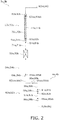
- Fig. 2 illustrates a refrigerant system in the periphery of indoor units 3a and 3b and external shutoff valve units 4a and 4b constituting the air conditioner 1 according to the first embodiment of the present disclosure.
- the air conditioner 1 is an apparatus that performs air conditioning (cooling and heating) in an air-conditioning target space in a building or the like through a vapor compression refrigeration cycle.
- the air conditioner 1 mainly includes an outdoor unit 2; a plurality of (in this case, two) indoor units 3a and 3b mutually connected in parallel; a liquid-refrigerant connection pipe 5 and a gas-refrigerant connection pipe 6 that connect the outdoor unit 2 to the indoor units 3a and 3b; a plurality of (in this case, two) external shutoff valve units 4a and 4b provided at the gas-refrigerant connection pipe 5; and a control unit 19 that controls components of the outdoor unit 2, the indoor units 3a and 3b, and the external shutoff valve units 4a and 4b.
- a vapor compression refrigerant circuit 10 of the air conditioner 1 is constituted by connecting the outdoor unit 2, the plurality of indoor units 3a and 3b, and the plurality of external shutoff valve units 4a and 4b to one another via the liquid-refrigerant connection pipe 5 and the gas-refrigerant connection pipe 6.
- the refrigerant circuit 10 is filled with a refrigerant such as R32.
- the liquid-refrigerant connection pipe 5 mainly includes a joint pipe portion extending from the outdoor unit 2, and branch pipe portions 5a and 5b branched at a position before the indoor units 3a and 3b into a plurality of (in this case, two) pipe portions.
- the gas-refrigerant connection pipe 6 mainly includes a joint pipe portion extending from the outdoor unit 2, first branch pipe portions 6a and 6b branched at a position before the indoor units 3a and 3b into a plurality of (in this case, two) pipe portions, and second branch pipe portions 6aa and 6bb that connect the external shutoff valve units 4a and 4b to the indoor units 3a and 3b.
- the indoor units 3a and 3b are arranged in air-conditioning target spaces in a building or the like. Being “arranged in air-conditioning target spaces” includes a situation in which the indoor units 3a and 3b are installed in the air-conditioning target spaces and a situation in which the indoor units 3a and 3b are not arranged in the air-conditioning target spaces but the indoor units 3a and 3b are connected to the air-conditioning target spaces via air ducts or the like.
- the indoor units 3a and 3b are connected to the outdoor unit 2 via the liquid-refrigerant connection pipe 5, the gas-refrigerant connection pipe 6, and the external shutoff valve units 4a and 4b, and constitute part of the refrigerant circuit 10 as described above.
- the indoor unit 3a and the indoor unit 3b have configurations similar to each other. Hence only the configuration of the indoor unit 3a is described.
- the description of the components of the indoor unit 3b is omitted while an index "b" is applied to each component instead of the index "a” indicating each component of the indoor unit 3a.
- the indoor unit 3a mainly includes an indoor expansion valve 51a and an indoor heat exchanger 52a.
- the indoor unit 3a includes an indoor liquid-refrigerant pipe 53a that connects the liquid side of the indoor heat exchanger 52a to the liquid-refrigerant connection pipe 5 (in this case, the branch pipe portion 5a), and an indoor gas-refrigerant pipe 54a that connects the gas side of the indoor heat exchanger 52a to the gas-refrigerant connection pipe 6 (in this case, the second branch pipe portion 6aa).
- the indoor expansion valve 51a is an electric expansion valve that decompresses the refrigerant.
- the indoor expansion valve 51a is provided in the indoor liquid-refrigerant pipe 53a.
- the indoor heat exchanger 52a is a heat exchanger that performs heat exchange between the refrigerant, which is circulated between the indoor unit 3a and the outdoor unit 2 via the liquid-refrigerant connection pipe 5 and the gas-refrigerant connection pipe 6, and the indoor air, which is sent to the air-conditioning target space.
- the indoor unit 3a includes an indoor fan 55a that sucks the indoor air into the indoor unit 3a, that causes the indoor air to exchange heat with the refrigerant in the indoor heat exchanger 52a, and then that sends the indoor air into the air-conditioning target space.
- the indoor unit 3a includes the indoor fan 55a as a fan that sends the indoor air, which serves as a cooling source or a heating source of the refrigerant flowing through the indoor heat exchanger 52a, to the indoor heat exchanger 52a.
- the indoor fan 55a is driven by an indoor fan motor 56a.
- the indoor liquid-refrigerant pipe 53a mainly includes a heat-exchange-side indoor liquid-refrigerant pipe 71a that connects the liquid side of the indoor heat exchanger 52a to the indoor expansion valve 51a, and a connection-side indoor liquid-refrigerant pipe 72a that connects the indoor expansion valve 51a to the liquid-refrigerant connection pipe 5 (in this case, the branch pipe portion 5a).
- the liquid side of the indoor heat exchanger 52a is connected to the heat-exchange-side indoor liquid-refrigerant pipe 71a by brazing.
- the heat-exchange-side indoor liquid-refrigerant pipe 71a is connected to the indoor expansion valve 51a by brazing (the brazing portion is referred to as brazing portion 81a).
- the indoor expansion valve 51a is connected to the connection-side indoor liquid-refrigerant pipe 72a by brazing (the brazing portion is referred to as brazing portion 82a).
- the connection-side indoor liquid-refrigerant pipe 72a is connected to the liquid-refrigerant connection pipe 5 (in this case, the branch pipe portion 5a) by mechanical pipe joint, such as flare connection (the portion of the mechanical pipe joint is referred to as pipe joint portion 83a).
- the pipe joint portion 83a is connected to the connection-side indoor liquid-refrigerant pipe 72a by brazing (the brazing portion is referred to as brazing portion 83aa).
- connection-side indoor liquid-refrigerant pipe 72a may be directly connected to the liquid-refrigerant connection pipe 5 (in this case, the branch pipe portion 5a) by brazing without the mechanical pipe joint such as the pipe joint portion 83a.
- the brazing portion 82a brazing the indoor expansion valve 51a and the connection-side indoor liquid-refrigerant pipe 72a is provided with a coating material 11a.
- a coating material 11a any material can be employed as long as the material can suppress corrosion of the brazing portion 82a.
- a coating material made of resin can be employed.
- a water-repellent material and a heat-insulating material are suitable.
- urethane resin can be employed.
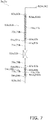
- the coating material 11a may be provided at the brazing portion 82a, or may be also provided at a portion other than the brazing portion 82a. For example, as illustrated in Fig.
- the coating material 11a may be provided in a range from the indoor expansion valve 51a to the pipe joint portion 83a of the connection-side indoor liquid-refrigerant pipe 72a (that is, so as to include the brazing portion 82a and the brazing portion 83aa).
- the coating material 11a may be provided in a range from the indoor expansion valve 51a to the brazing portion brazing the connection-side indoor liquid-refrigerant pipe 72a and the liquid-refrigerant connection pipe 5 (in this case, the branch pipe portion 5a).
- the gas side of the indoor heat exchanger 52a is connected to the indoor gas-refrigerant pipe 54a by brazing.
- the indoor gas-refrigerant pipe 54a is connected to the gas-refrigerant connection pipe 6 (in this case, the second branch pipe portion 6aa) by mechanical pipe joint, such as flare connection (the portion of the mechanical pipe joint is referred to as pipe joint portion 84a).
- the pipe joint portion 84a is connected to the indoor gas-refrigerant pipe 54a by brazing (the brazing portion is referred to as brazing portion 84aa).
- the indoor gas-refrigerant pipe 54a may be directly connected to the gas-refrigerant connection pipe 6 (in this case, the second branch pipe portion 6aa) by brazing.
- the indoor unit 3a is provided with a refrigerant sensor 57a serving as refrigerant leakage detecting means for detecting leakage of the refrigerant.
- the refrigerant sensor 57a is provided in the indoor unit 3a in this case; however, it is not limited thereto.
- the refrigerant sensor 57a may be provided, for example, at a remote controller for operating the indoor unit 3a, or in the air-conditioning target space where the indoor unit 3a is arranged.
- the refrigerant leakage detecting means may be the refrigerant sensor 57a that directly detects the leaked refrigerant as described above, or alternatively, although it is not employed in this case, the refrigerant leakage detecting means may be one that estimates the presence or amount of leaked refrigerant on the basis of the relationship between the temperature of the refrigerant in the indoor heat exchanger 52a and the atmospheric temperature of the indoor heat exchanger 52a.
- the outdoor unit 2 is arranged outside the air-conditioning target space or outside the building or the like.
- the outdoor unit 2 is connected to the indoor units 3a and 3b via the liquid-refrigerant connection pipe 5, the gas-refrigerant connection pipe 6, and the external shutoff valve units 4a and 4b, and constitutes part of the refrigerant circuit 10 as described above.
- the outdoor unit 2 mainly includes a compressor 21 and an outdoor heat exchanger 23.
- the outdoor unit 2 includes a switching mechanism 22 that switches the operating state between a radiation operating state in which the outdoor heat exchanger 23 functions as a radiator of the refrigerant, and an evaporation operating state in which the outdoor heat exchanger 23 functions as an evaporator of the refrigerant.
- the switching mechanism 22 is connected to the suction side of the compressor 21 via a suction refrigerant pipe 31.
- the discharge side of the compressor 21 is connected to the switching mechanism 22 via a discharge refrigerant pipe 32.
- the switching mechanism 22 is connected to the gas side of the outdoor heat exchanger 23 via a first outdoor gas-refrigerant pipe 33.
- the liquid side of the outdoor heat exchanger 23 is connected to the liquid-refrigerant connection pipe 5 via an outdoor liquid-refrigerant pipe 34.
- the connection portion of the outdoor liquid-refrigerant pipe 34 with respect to the liquid-refrigerant connection pipe 5 is provided with a liquid-side shutoff valve 27.
- the switching mechanism 22 is connected to the gas-refrigerant connection pipe 6 via a second outdoor gas-refrigerant pipe 35.
- the connection portion of the second outdoor gas-refrigerant pipe 35 with respect to the gas-refrigerant connection pipe 6 is provided with a gas-side shutoff valve 28.
- the liquid-side shutoff valve 27 and the gas-side shutoff valve 28 are valves that are manually opened and closed.
- the compressor 21 is a device for compressing the refrigerant.
- a closed-structure compressor in which a compression element (not illustrated) of positive-displacement type, such as rotary type or scroll type, is rotationally driven by a compressor motor 21a is used.
- the switching mechanism 22 is a device that can switch the flow of the refrigerant in the refrigerant circuit 10 such that, when the outdoor heat exchanger 23 functions as the radiator of the refrigerant (hereinafter, the situation is referred to as "outdoor radiation state"), the switching mechanism 22 connects the discharge side of the compressor 21 to the gas side of the outdoor heat exchanger 23 (see solid lines of the switching mechanism 22 in Fig. 1 ); and, when the outdoor heat exchanger 23 functions as the evaporator of the refrigerant (hereinafter, the situation is referred to as "outdoor evaporation state"), the switching mechanism 22 connects the suction side of the compressor 21 to the gas side of the outdoor heat exchanger 23 (see broken lines of the switching mechanism 22 in Fig. 1 ).
- the switching mechanism 22 is, for example, a four-way switching valve.
- the outdoor heat exchanger 23 is a heat exchanger that performs heat exchange between the outdoor air and the refrigerant, which is circulated between the outdoor unit 2 and the indoor units 3a and 3b via the liquid-refrigerant connection pipe 5 and the gas-refrigerant connection pipe 6.
- the outdoor unit 2 includes an outdoor fan 24 that sucks the outdoor air into the outdoor unit 2 that causes the outdoor air to exchange heat with the refrigerant in the outdoor heat exchanger 23, and then that discharges the outdoor air to the outside. That is, the outdoor unit 2 includes the outdoor fan 24 as a fan that sends the outdoor air, which serves as a cooling source or a heating source of the refrigerant flowing through the outdoor heat exchanger 23, to the outdoor heat exchanger 23.
- the outdoor fan 24 is driven by an outdoor fan motor 24a.
- the air conditioner 1 Focusing only on the compressor 21, the outdoor heat exchanger 23, the liquid-refrigerant connection pipe 5, the indoor expansion valves 51a and 51b, the indoor heat exchangers 52a and 52b, and the gas-refrigerant connection pipe 6, the air conditioner 1 performs an operation (cooling operation) of circulating the refrigerant in the order of the compressor 21, the outdoor heat exchanger 23, the liquid-refrigerant connection pipe 5, the indoor expansion valves 51a and 51b, the indoor heat exchangers 52a and 52b, the gas-refrigerant connection pipe 6, and the compressor 21.
- the air conditioner 1 Focusing only on the compressor 21, the outdoor heat exchanger 23, the liquid-refrigerant connection pipe 5, the indoor expansion valves 51a and 51b, the indoor heat exchangers 52a and 52b, and the gas-refrigerant connection pipe 6, the air conditioner 1 performs an operation (heating operation) of circulating the refrigerant in the order of the compressor 21, the gas-refrigerant connection pipe 6, the indoor heat exchangers 52a and 52b, the indoor expansion valves 51a and 51b, the liquid-refrigerant connection pipe 5, the outdoor heat exchanger 23, and the compressor 21.
- the switching mechanism 22 is switched to the outdoor radiation state in cooling operation, and the switching mechanism 22 is switched to the outdoor evaporation state in heating operation.
- an outdoor expansion valve 25 and a liquid-pressure adjustment expansion valve 26 are provided in the outdoor liquid-refrigerant pipe 34.
- the outdoor expansion valve 25 is an electric expansion valve that decompresses the refrigerant in heating operation, and is provided in a portion of the outdoor liquid-refrigerant pipe 34 near the liquid side of the outdoor heat exchanger 23.
- the liquid-pressure adjustment expansion valve 26 is an electric expansion valve that decompresses the refrigerant so that the refrigerant flowing through the liquid-refrigerant connection pipe 5 is brought into a gas-liquid two-phase state in cooling operation, and is provided in a portion of the outdoor liquid-refrigerant pipe 34 near the liquid-refrigerant connection pipe 5. That is, the liquid-pressure adjustment expansion valve 26 is provided in a portion of the outdoor liquid-refrigerant pipe 34 nearer to the liquid-refrigerant connection pipe 5 than the outdoor expansion valve 25.
- the air conditioner 1 performs two-phase refrigerant feed of sending the refrigerant in the gas-liquid two-phase state to the liquid-refrigerant connection pipe 5 by the liquid-pressure adjustment expansion valve 26 and hence sending the refrigerant from the outdoor unit 2 to the indoor units 3a and 3b in cooling operation.
- a refrigerant return pipe 41 is connected to the outdoor liquid-refrigerant pipe 34, and a refrigerant cooler 45 is provided.
- the refrigerant return pipe 41 is a refrigerant pipe that branches part of the refrigerant flowing through the outdoor liquid-refrigerant pipe 34 and sends the refrigerant to the compressor 21.
- the refrigerant cooler 45 is a heat exchanger that cools the refrigerant flowing through a portion of the outdoor liquid-refrigerant pipe 34 nearer to the outdoor heat exchanger 23 than the liquid-pressure adjustment expansion valve 26.
- the outdoor expansion valve 25 is provided in a portion of the outdoor liquid-refrigerant pipe 34 nearer to the outdoor heat exchanger 23 than the refrigerant cooler 45.
- the liquid-pressure adjustment expansion valve 26 is provided in a portion of the outdoor liquid-refrigerant pipe 34 nearer to the liquid-refrigerant connection pipe 5 than the portion to which the refrigerant cooler 45 is connected (in this case, between the refrigerant cooler 45 and the liquid-side shutoff valve 27).
- the refrigerant return pipe 41 is a refrigerant pipe that sends the refrigerant branched from the outdoor liquid-refrigerant pipe 34 to the suction side of the compressor 21.
- the refrigerant return pipe 41 mainly includes a refrigerant return inlet pipe 42 and a refrigerant return outlet pipe 43.
- the refrigerant return inlet pipe 42 is a refrigerant pipe that branches part of the refrigerant flowing through the outdoor liquid-refrigerant pipe 34 from a portion between the liquid side of the outdoor heat exchanger 23 and the liquid-pressure adjustment expansion valve 26 (in this case, a portion between the outdoor expansion valve 25 and the refrigerant cooler 45) and sends the refrigerant to the inlet of the refrigerant cooler 45 on the side of the refrigerant return pipe 41.
- the refrigerant return inlet pipe 42 is provided with a refrigerant return expansion valve 44 that adjusts the flow rate of the refrigerant flowing through the refrigerant cooler 45 while decompressing the refrigerant flowing through the refrigerant return pipe 41.
- the refrigerant return expansion valve 44 is an electric expansion valve.
- the refrigerant return outlet pipe 43 is a refrigerant pipe that sends the refrigerant from the outlet of the refrigerant cooler 45 on the side of the refrigerant return pipe 41 to the suction refrigerant pipe 31.
- the refrigerant cooler 45 cools the refrigerant flowing through the outdoor liquid-refrigerant pipe 34 by using the refrigerant flowing through the refrigerant return pipe 41.
- the outdoor unit 2 is provided with various sensors. To be specific, the outdoor unit 2 is provided with a discharge pressure sensor 36 that detects a pressure (discharge pressure Pd) of the refrigerant discharged from the compressor 21. In addition, the outdoor unit 2 is provided with an outdoor heat-exchange liquid-side sensor 37 that detects a temperature Tol (outdoor heat-exchange outlet temperature Tol) of the refrigerant on the liquid side of the outdoor heat exchanger 23, and is provided with a liquid-pipe temperature sensor 38 that detects a temperature (liquid-pipe temperature Tlp) of the refrigerant in a portion of the outdoor liquid-refrigerant pipe 34 between the refrigerant cooler 45 and the liquid-pressure adjustment expansion valve 26.
- a discharge pressure sensor 36 that detects a pressure (discharge pressure Pd) of the refrigerant discharged from the compressor 21.
- the outdoor unit 2 is provided with an outdoor heat-exchange liquid-side sensor 37 that detects a temperature Tol (outdoor heat-exchange outlet temperature Tol)
- the external shutoff valve units 4a and 4b are arranged in the building or the like. In this case, the external shutoff valve units 4a and 4b are arranged outside the air-conditioning target spaces unlike the indoor units 3a and 3b.
- the external shutoff valve units 4a and 4b, together with the gas-refrigerant connection pipe 6, are provided between the indoor units 3a and 3b and the outdoor unit 2, and constitute part of the refrigerant circuit 10.
- the external shutoff valve unit 4a and the external shutoff valve unit 4b have configurations similar to each other. Hence only the configuration of the external shutoff valve unit 4a is described.
- the description of the components of the external shutoff valve unit 4b is omitted while an index "b" is applied to each component instead of the index "a” indicating each component of the external shutoff valve unit 4a.
- the external shutoff valve unit 4a is provided in the gas-refrigerant connection pipe 6, and mainly includes a gas-side shutoff valve 58a.
- the external shutoff valve unit 4a includes a gas connection pipe 62a that is connected to the first branch pipe portion 6a, which is a portion of the gas-refrigerant connection pipe 6 on the side of the outdoor unit 2, and that is connected to the second branch pipe portion 6aa, which is a portion of the gas-refrigerant connection pipe 6 on the side of the indoor unit 3a.
- the gas-side shutoff valve 58a is an electric expansion valve that shuts off the flow of the refrigerant that is circulated between the indoor unit 3a and the outdoor unit 2 via the gas-refrigerant connection pipe 6.
- the gas-side shutoff valve 58a is provided in the gas connection pipe 62a. That is, the gas-side shutoff valve 58a is connected to the gas side of the indoor heat exchanger 52a via the indoor gas-refrigerant pipe 54a of the indoor unit 3a, the second branch pipe portion 6aa of the gas-refrigerant connection pipe 6, and the gas connection pipe 62a of the external shutoff valve unit 4a.
- the gas-side shutoff valve 58a may not be an electric expansion valve and may be an electromagnetic valve.
- the gas connection pipe 62a mainly includes an indoor-side gas connection pipe 66a that is connected to a portion of the gas-refrigerant connection pipe 6 on the side of the indoor unit 3a (in this case, the second branch pipe portion 6aa), and an outdoor-side gas connection pipe 67a that is connected to a portion of the gas-refrigerant connection pipe 6 on the side of the outdoor unit 2 (in this case, the first branch pipe portion 6a).
- the gas-side shutoff valve 58a is connected to the indoor-side gas connection pipe 66a by brazing (the brazing portion is referred to as brazing portion 91a).
- the gas-side shutoff valve 58a is connected to the outdoor-side gas connection pipe 67a by brazing (the brazing portion is referred to as brazing portion 92a).
- the indoor-side gas connection pipe 66a is connected to the gas-refrigerant connection pipe 6 (in this case, the second branch pipe portion 6aa) by mechanical pipe joint, such as flare connection (the portion of the mechanical pipe joint is referred to as pipe joint portion 95a).
- the pipe joint portion 95a is connected to the indoor-side gas connection pipe 66a by brazing (the brazing portion is referred to as brazing portion 95aa).
- the indoor-side gas connection pipe 66a may be directly connected to the gas-refrigerant connection pipe 6 (in this case, the second branch pipe portion 6aa) by brazing.
- the outdoor-side gas connection pipe 67a is connected to the gas-refrigerant connection pipe 6 (in this case, the first branch pipe portion 6a) by mechanical pipe joint, such as flare connection (the portion of the mechanical pipe joint is referred to as pipe joint portion 96a).
- the pipe joint portion 96a is connected to the outdoor-side gas connection pipe 67a by brazing (the brazing portion is referred to as brazing portion 96aa).
- the outdoor-side gas connection pipe 67a may be directly connected to the gas-refrigerant connection pipe 6 (in this case, the first branch pipe portion 6a) by brazing.
- the control unit 19 is constituted by being connected to control boards or the like (not illustrated) provided in, for example, the outdoor unit 2 and the indoor units 3a and 3b to communicate therewith. In Fig. 1 , however, the control unit 19 is illustrated at a position separated from the outdoor unit 2, the indoor units 3a and 3b, and the external shutoff valve units 4a and 4b for the convenience of illustration.
- the control unit 19 controls the components 21, 22, 24, 25, 26, 44, 51a, 51b, 55a, 55b, 58a, and 58b of the air conditioner 1 (in this case, the outdoor unit 2, the indoor units 3a and 3b, and the external shutoff valve units 4a and 4b), that is, controls the entire operation of the air conditioner 1 in accordance with the detection signals of the above-described various sensors 36, 37, 38, 57a, and 57b.
- the operation of the air conditioner 1 when the refrigerant does not leak is described next with reference to Fig. 1 .
- the air conditioner 1 performs cooling operation and heating operation.
- the air conditioner 1 performs two-phase refrigerant feed of sending the refrigerant in the gas-liquid two-phase state to the liquid-refrigerant connection pipe 5 by the liquid-pressure adjustment expansion valve 26 provided in the outdoor liquid-refrigerant pipe 34 and hence sending the refrigerant from the outdoor unit 2 to the indoor units 3a and 3b in cooling operation.
- the operation of the air conditioner 1 which is described below is performed by the control unit 19 that controls the components of the air conditioner 1.
- cooling operation for example, when all the indoor units 3a and 3b perform cooling operation (that is, operation in which all the indoor heat exchangers 52a and 52b function as the evaporators of the refrigerant and the outdoor heat exchanger 23 functions as the radiator of the refrigerant), the switching mechanism 22 is switched to the outdoor radiation state (the state in which the switching mechanism 22 is indicated by solid lines in Fig. 1 ), and the compressor 21, the outdoor fan 24, and the indoor fans 55a and 55b are driven.
- the high-pressure refrigerant discharged from the compressor 21 is sent to the outdoor heat exchanger 23 via the switching mechanism 22.
- the refrigerant sent to the outdoor heat exchanger 23 is condensed by being cooled through heat exchange with the outdoor air supplied by the outdoor fan 24 in the outdoor heat exchanger 23 that functions as the radiator of the refrigerant.
- the refrigerant flows out from the outdoor unit 2 via the outdoor expansion valve 25, the refrigerant cooler 45, the liquid-pressure adjustment expansion valve 26, and the liquid-side shutoff valve 27.
- the refrigerant flowing out from the outdoor unit 2 is branched and sent to the indoor units 3a and 3b via the liquid-refrigerant connection pipe 5.
- the refrigerant sent to the indoor units 3a and 3b is decompressed by the indoor expansion valves 51a and 51b to be at low pressure.
- the refrigerant is sent to the indoor heat exchangers 52a and 52b.
- the refrigerant sent to the indoor heat exchangers 52a and 52b is evaporated by being heated through heat exchange with the indoor air supplied from the air-conditioning target spaces by the indoor fans 55a and 55b in the indoor heat exchangers 52a and 52b that function as the evaporators of the refrigerant.
- the refrigerant flows out from the indoor units 3a and 3b.
- the indoor air cooled by the indoor heat exchangers 52a and 52b is sent to the air-conditioning target spaces and the air-conditioning target spaces are cooled by using the cooled indoor air.
- the refrigerant flowing out from the indoor units 3a and 3b is sent to the external shutoff valve units 4a and 4b via the second branch pipe portions 6aa and 6bb of the gas-refrigerant connection pipe 6.
- the refrigerant sent to the external shutoff valve units 4a and 4b passes through the gas-side shutoff valves 58a and 58b and then flows out from the external shutoff valve units 4a and 4b.
- the refrigerant flowing out from the external shutoff valve units 4a and 4b is joined at the gas-refrigerant connection pipe 6 and sent to the outdoor unit 2.
- the refrigerant sent to the outdoor unit 2 is sucked into the compressor 21 via the gas-side shutoff valve 28 and the switching mechanism 22.
- the air conditioner 1 performs two-phase refrigerant feed of sending the refrigerant in the gas-liquid two-phase state to the liquid-refrigerant connection pipe 5 by the liquid-pressure adjustment expansion valve 26 and hence sending the refrigerant from the outdoor unit 2 to the indoor units 3a and 3b.
- the refrigerant flowing through the outdoor liquid-refrigerant pipe 34 is cooled by the refrigerant return pipe 41 and the refrigerant cooler 45 to reduce variation in the liquid-pipe temperature Tlp in the portion of the outdoor liquid-refrigerant pipe 34 between the refrigerant cooler 45 and the liquid-pressure adjustment expansion valve 26, so that the two-phase refrigerant feed can be properly performed.
- the control unit 19 causes the liquid-pressure adjustment expansion valve 26 to decompress the refrigerant so that the refrigerant flowing through the liquid-refrigerant connection pipe 5 is brought into the gas-liquid two-phase state.
- the refrigerant decompressed by the liquid-pressure adjustment expansion valve 26 is the refrigerant at medium pressure that is lower than the pressure of the high-pressure refrigerant and higher than the pressure of the low-pressure refrigerant.
- the control unit 19 controls the opening degree of the liquid-pressure adjustment expansion valve 26 so that a degree of subcooling SCo of the refrigerant on the liquid side of the outdoor heat exchanger 23 becomes a target degree of subcooling SCot.
- control unit 19 obtains the degree of subcooling SCo of the refrigerant on the liquid side of the outdoor heat exchanger 23 from the outdoor heat-exchange liquid-side temperature Tol.
- the control unit 19 obtains the degree of subcooling SCo of the refrigerant on the liquid side of the outdoor heat exchanger 23 by subtracting the outdoor heat-exchange outlet temperature Tol from a temperature Toc of the refrigerant, which is obtained by converting the discharge pressure Pd into a saturation temperature.
- the control unit 19 performs control to increase the opening degree of the liquid-pressure adjustment expansion valve 26 if the degree of subcooling SCo is larger than the target degree of subcooling SCot, and performs control to decrease the opening degree of the liquid-pressure adjustment expansion valve 26 if the degree of subcooling SCo is smaller than the target degree of subcooling SCot. At this time, the control unit 19 performs control to fix the opening degree of the outdoor expansion valve 25 to a fully opened state.
- the refrigerant flowing through the liquid-refrigerant connection pipe 5 is brought into the gas-liquid two-phase state.
- the liquid-refrigerant connection pipe 5 is less likely filled with the refrigerant in the liquid state as compared with the case where the refrigerant flowing through the liquid-refrigerant connection pipe 5 is in the liquid state.
- the amount of refrigerant existing in the liquid-refrigerant connection pipe 5 can be decreased by that amount.
- the control unit 19 causes the temperature (the liquid-pipe temperature Tlp) of the refrigerant in the portion of the outdoor liquid-refrigerant pipe 34 between the refrigerant cooler 45 and the liquid-pressure adjustment expansion valve 26 to be constant by cooling the refrigerant flowing through the portion of the outdoor liquid-refrigerant pipe 34 nearer to the outdoor heat exchanger 23 than the liquid-pressure adjustment expansion valve 26 by the refrigerant cooler 45 by using the refrigerant flowing through the refrigerant return pipe 41.
- the control unit 19 controls the opening degree of the refrigerant return expansion valve 44 so that the temperature (the liquid-pipe temperature Tlp) of the refrigerant in the portion of the outdoor liquid-refrigerant pipe 34 between the refrigerant cooler 45 and the liquid-pressure adjustment expansion valve 26 becomes a target liquid-pipe temperature Tlpt.
- the control unit 19 performs control to increase the opening degree of the refrigerant return expansion valve 44 if the liquid-pipe temperature Tlp is higher than the target liquid-pipe temperature Tlpt, and performs control to decrease the opening degree of the refrigerant return expansion valve 44 if the liquid-pipe temperature Tlp is lower than the target liquid-pipe temperature Tlpt.
- the temperature (the liquid-pipe temperature Tlp) of the refrigerant in the portion of the outdoor liquid-refrigerant pipe 34 between the refrigerant cooler 45 and the liquid-pressure adjustment expansion valve 26 can be maintained constant at the target liquid-pipe temperature Tlpt.
- the liquid-pipe temperature Tlp constant and reducing variation, the refrigerant flowing through the liquid-refrigerant connection pipe 5 after decompressed by the liquid-pressure adjustment expansion valve 26 can be reliably maintained in a desirable gas-liquid two-phase state.
- heating operation for example, when all the indoor units 3a and 3b perform heating operation (that is, operation in which all the indoor heat exchangers 52a and 52b function as the radiators of the refrigerant and the outdoor heat exchanger 23 functions as the evaporator of the refrigerant), the switching mechanism 22 is switched to the outdoor evaporation state (the state in which the switching mechanism 22 is indicated by broken lines in Fig. 1 ), and the compressor 21, the outdoor fan 24, and the indoor fans 55a and 55b are driven.
- heating operation that is, operation in which all the indoor heat exchangers 52a and 52b function as the radiators of the refrigerant and the outdoor heat exchanger 23 functions as the evaporator of the refrigerant
- the switching mechanism 22 is switched to the outdoor evaporation state (the state in which the switching mechanism 22 is indicated by broken lines in Fig. 1 ), and the compressor 21, the outdoor fan 24, and the indoor fans 55a and 55b are driven.
- the high-pressure refrigerant discharged from the compressor 21 flows out from the outdoor unit 2 via the switching mechanism 22 and the gas-side shutoff valve 28.
- the refrigerant flowing out from the outdoor unit 2 is branched and sent to the external shutoff valve units 4a and 4b via the gas-refrigerant connection pipe 6.
- the refrigerant sent to the external shutoff valve units 4a and 4b passes through the gas-side shutoff valves 58a and 58b and then flows out from the external shutoff valve units 4a and 4b.
- the refrigerant flowing out from the external shutoff valve units 4a and 4b is sent to the indoor units 3a and 3b via the second branch pipe portions 6aa and 6bb of the gas-refrigerant connection pipe 6.
- the refrigerant sent to the indoor units 3a and 3b is sent to the indoor heat exchangers 52a and 52b.
- the high-pressure refrigerant sent to the indoor heat exchangers 52a and 52b is condensed by being cooled through heat exchange with the indoor air supplied from the air-conditioning target spaces by the indoor fans 55a and 55b in the indoor heat exchangers 52a and 52b that function as the radiators of the refrigerant.
- the refrigerant flows out from the indoor units 3a and 3b via the indoor expansion valves 51a and 51b.
- the indoor air heated by the indoor heat exchangers 52a and 52b is sent to the air-conditioning target spaces and the air-conditioning target spaces are heated by using the heated indoor air.
- the refrigerant flowing out from the indoor units 3a and 3b is joined at the liquid-refrigerant connection pipe 5 and sent to the outdoor unit 2.
- the refrigerant sent to the outdoor unit 2 is sent to the outdoor expansion valve 25 via the liquid-side shutoff valve 27, the liquid-pressure adjustment expansion valve 26, and the refrigerant cooler 45.
- the refrigerant sent to the outdoor expansion valve 25 is decompressed by the outdoor expansion valve 25 to be at low pressure and then is sent to the outdoor heat exchanger 23.
- the refrigerant sent to the outdoor heat exchanger 23 is evaporated by being heated through heat exchange with the outdoor air supplied by the outdoor fan 24.
- the refrigerant is sucked into the compressor 21 via the switching mechanism 22.
- control unit 19 performs control to fix the opening degree of the liquid-pressure adjustment expansion valve 26 to a fully opened state.
- the opening degree of the refrigerant return expansion valve 44 is brought into a fully closed state to inhibit the refrigerant from flowing to the refrigerant return pipe 41.
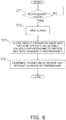
- Fig. 3 is a flowchart of an operation when a refrigerant leaks in the air conditioner 1 according to the first embodiment of the present disclosure.
- the operation of the air conditioner 1 when the refrigerant leaks which is described below is performed by the control unit 19 that controls the components of the air conditioner 1 (the outdoor unit 2, the indoor units 3a and 3b, and the external shutoff valve units 4a and 4b) like the operation when the refrigerant does not leak.
- the air conditioner 1 is provided with the refrigerant sensors 57a and 57b serving as the refrigerant leakage detecting means as described above.
- the indoor expansion valves 51a and 51b and the gas-side shutoff valves 58a and 58b are closed in accordance with the information of the refrigerant sensors 57a and 57b.
- the indoor units 3a and 3b can be isolated. Accordingly, the refrigerant can be inhibited from flowing from the refrigerant connection pipes 5 and 6 to the indoor units 3a and 3b.
- the indoor expansion valves 51a and 51b are used also as liquid-side shutoff valves and are closed together with the gas-side shutoff valves 58a and 58b, thereby providing a refrigerant shutoff function when the refrigerant leaks from the indoor units 3a and 3b.
- step ST1 when the refrigerant sensors 57a and 57b detect leakage of the refrigerant (step ST1), the control unit 19 closes the indoor expansion valves 51a and 51b and the gas-side shutoff valves 58a and 58b (step ST4).
- step ST2 when leakage of the refrigerant is detected in step ST1, an alarm may be given (step ST2).
- step ST3 the compressor 21 may be stopped (step ST3) to suppress an excessive increase in the pressure of the refrigerant.
- the indoor expansion valves 51a and 51b and the gas-side shutoff valves 58a and 58b are closed in accordance with the information of the refrigerant sensors 57a and 57b serving as the refrigerant leakage detecting means when the refrigerant leaks.
- the refrigerant is inhibited from flowing from the refrigerant connection pipes 5 and 6 to the indoor units 3a and 3b, and increase in concentration of the refrigerant in the air-conditioning target spaces can be suppressed.
- the air conditioner 1 and the indoor units 3a and 3b according to this embodiment have the following features.
- shutoff valves on both the liquid sides and the gas sides of the indoor units 3a and 3b may increase the cost and the sizes of the indoor units 3a and 3b.
- connection-side indoor liquid-refrigerant pipes 72a and 72b that connect the indoor expansion valves 51a and 51b to the liquid-refrigerant connection pipe 5 are connected to the indoor expansion valves 51a and 51b by brazing.
- the brazing portions 82a and 82b brazing the indoor expansion valves 51a and 51b and the connection-side indoor liquid-refrigerant pipes 72a and 72b may corrode and the refrigerant may leak from the corroding portions.
- the refrigerant When the refrigerant leaks from the brazing portions 82a and 82b, the refrigerant is continuously supplied from the liquid-refrigerant connection pipe 5 to the brazing portions 82a and 82b although the indoor expansion valves 51a and 51b are closed to function as the shutoff valves on the liquid sides of the indoor units 3a and 3b.
- the refrigerant may continuously leak from the indoor units 3a and 3b to the air-conditioning target spaces.
- the indoor expansion valves 51a and 51b can be used also as the shutoff valves on the liquid sides of the indoor units 3a and 3b.
- the indoor expansion valves 51a and 51b can be used also as the shutoff valves on the liquid sides of the indoor units 3a and 3b, the increase in the cost and the sizes of the indoor units 3a and 3b can be suppressed by that amount.
- the refrigerant shutoff function for the situation in which the refrigerant leaks from the indoor units 3a and 3b can be added while the increase in the cost and the sizes of the indoor units 3a and 3b due to the provision of the shutoff valves on the liquid sides of the indoor units 3a and 3b is reduced as much as possible.
- the gas-side shutoff valves 58a and 58b are arranged in the external shutoff valve units 4a and 4b located outside the indoor units 3a and 3b as described above, the increase in the sizes of the indoor units 3a and 3b can be suppressed.
- the outdoor unit 2 includes the liquid-pressure adjustment expansion valve 26 as described above, the two-phase refrigerant feed of decompressing the refrigerant to be brought into the gas-liquid two-phase state in the outdoor unit 2 and then sending the refrigerant to the indoor units 3a and 3b via the liquid-refrigerant connection pipe 5 can be performed.
- the amount of refrigerant held by the entire air conditioner can be decreased by the amount by which the refrigerant flowing through the liquid-refrigerant connection pipe 5 turns into the gas-liquid two-phase state through the two-phase refrigerant feed.
- the amount of refrigerant held by the entire air conditioner can be decreased by a certain degree through the two-phase refrigerant feed, when the refrigerant leaks from the indoor units 3a and 3b, the concentration of the refrigerant increases in the air-conditioning target spaces where the indoor units 3a and 3b involving leakage of the refrigerant are arranged, and the concentration may exceed its permissible value. In such a case, the two-phase refrigerant feed is not occasionally sufficient for the countermeasure to leakage of the refrigerant.
- the coating materials 11a and 11b at the brazing portions 82a and 82b as described above, leakage of the refrigerant from the brazing portions 82a and 82b is reduced, and the indoor expansion valves 51a and 51b can be used also as the shutoff valves on the liquid sides of the indoor units 3a and 3b.
- the refrigerant shutoff function for the situation in which the refrigerant leaks from the indoor units 3a and 3b can be added while the increase in the cost and the sizes of the indoor units 3a and 3b due to the provision of the shutoff valves on the liquid sides of the indoor units 3a and 3b is reduced as much as possible.
- the addition of the refrigerant shutoff function makes the countermeasure to leakage of the refrigerant sufficient.
- only the indoor expansion valves 51a and 51b are provided in the indoor liquid-refrigerant pipes 53a and 53b as illustrated in Fig. 2 in the indoor units 3a and 3b arranged in the air-conditioning target spaces.
- filters 73a and 73b for reducing inflow of foreign substances and so forth to the indoor expansion valves 51a and 51b may be provided in the connection-side indoor liquid-refrigerant pipes 72a and 72b as illustrated in Fig. 4 in the indoor units 3a and 3b.
- the filters 73a and 73b are also connected to the connection-side indoor liquid-refrigerant pipes 72a and 72b by brazing.
- connection-side indoor liquid-refrigerant pipes 72a and 72b include first connection-side indoor liquid-refrigerant pipes 74a and 74b connected to the indoor expansion valves 51a and 51b, and second connection-side indoor liquid-refrigerant pipes 75a and 75b connected to the liquid-refrigerant connection pipe 5 (in this case, the branch pipe portions 5a and 5b).
- the filters 73a and 73b are connected between the first connection-side indoor liquid-refrigerant pipes 74a and 74b and the second connection-side indoor liquid-refrigerant pipes 75a and 75b.
- the filters 73a and 73b are connected to the first connection-side indoor liquid-refrigerant pipes 74a and 74b and the second connection-side indoor liquid-refrigerant pipes 75a and 75b by brazing (the brazing portions are referred to as brazing portions 85a, 85b, 86a, and 86b). Due to this, the brazing portions 85a, 85b, 86a, and 86b may corrode and the refrigerant may leak from the corroding portions.
- the brazing portions 85a, 85b, 86a, and 86b brazing the filters 73a and 73b with the first connection-side indoor liquid-refrigerant pipes 74a and 74b and the second connection-side indoor liquid-refrigerant pipes 75a and 75b are also provided with coating materials 11a, 11b, 12a, and 12b.
- the first connection-side indoor liquid-refrigerant pipes 74a and 74b including the brazing portions 82a and 82b and the brazing portions 85a and 85b are provided with the coating materials 11a and 11b.
- the second connection-side indoor liquid-refrigerant pipes 75a and 75b including the brazing portions 86a and 86b and the brazing portions 83aa and 83bb are provided with the coating materials 12a and 12b.
- the coating materials 12a and 12b may be provided to include the brazing portions brazing the second connection-side indoor liquid-refrigerant pipes 75a and 75b and the liquid-refrigerant connection pipe 5 (in this case, the branch pipe portion 5a).
- the way of providing the coating materials is not limited to the above.
- a coating material may be provided at each of the brazing portions 82a, 82b, 85a, 85b, 86a, 86b, 83aa, and 83bb, or may be provided collectively at all the brazing portions 82a, 82b, 85a, 85b, 86a, 86b, 83aa, and 83bb including the filters 73a and 73b.
- the refrigerant shutoff function for the situation in which the refrigerant leaks from the indoor units 3a and 3b can be added while the increase in the cost and the sizes of the indoor units 3a and 3b due to the provision of the shutoff valves on the liquid sides of the indoor units 3a and 3b is reduced as much as possible.
- the gas-side shutoff valves 58a and 58b are connected to the gas connection pipes 62a and 62b connected to the gas-refrigerant connection pipe 6 (the indoor-side gas connection pipes 66a and 66b and the outdoor-side gas connection pipes 67a and 67b) by brazing. Due to this, the brazing portions 92a and 92b brazing the gas-side shutoff valves 58a and 58b and the outdoor-side gas connection pipes 67a and 67b may corrode and the refrigerant may leak from the corroding portions.
- the external shutoff valve units 4a and 4b are arranged outside the air-conditioning target spaces. Hence, even when the refrigerant leaks from the brazing portions 92a and 92b, the refrigerant hardly leaks to the air-conditioning target spaces.
- the brazing portions 92a and 92b brazing the gas-side shutoff valves 58a and 58b and the outdoor-side gas connection pipes 67a and 67b are also provided with coating materials 13a and 13b.
- the coating materials 13a and 13b may be provided at only the brazing portions 92a and 92b, or may be also provided at a portion other than the brazing portions 92a and 92b.
- Fig. 5 As illustrated in Fig. 5 , the brazing portions 92a and 92b brazing the gas-side shutoff valves 58a and 58b and the outdoor-side gas connection pipes 67a and 67b are also provided with coating materials 13a and 13b.
- the coating materials 13a and 13b may be provided at only the brazing portions 92a and 92b, or may be also provided at a portion other than the brazing portions 92a and 92b.
- the coating materials 13a and 13b may be provided in a range from the gas-side shutoff valves 58a and 58b to the pipe joint portions 96a and 96b of the outdoor-side gas connection pipes 67a and 67b (that is, so as to include the brazing portions 92a and 92b and the brazing portions 96aa and 96bb).
- the coating materials 13a and 13b may be provided in a range from the gas-side shutoff valves 58a and 58b to the brazing portions brazing the outdoor-side gas connection pipes 67a and 67b and the gas-refrigerant connection pipe 6 (in this case, the first branch pipe portions 6a and 6b).
- the brazing portions 92a and 92b brazing the gas-side shutoff valves 58a and 58b and the outdoor-side gas connection pipes 67a and 67b are provided with the coating materials 13a and 13b; however, it is not limited to the above.
- the brazing portions 92a and 92b brazing the gas-side shutoff valves 58a and 58b and the outdoor-side gas connection pipes 67a and 67b may be provided with the coating materials 13a and 13b.
- the indoor expansion valves 51a and 51b of the indoor units 3a and 3b are used also as the liquid-side shutoff valves.
- the gas-side shutoff valves 58a and 58b are provided at the external shutoff valve units 4a and 4b.
- the gas-side shutoff valves 58a and 58b may be provided at the indoor units 3a and 3b as illustrated in Fig.
- the indoor gas-refrigerant pipes 54a and 54b mainly include heat-exchange-side indoor gas-refrigerant pipes 76a and 76b that connect the gas sides of the indoor heat exchangers 52a and 52b to the gas-side shutoff valves 58a and 58b, and connection-side indoor gas-refrigerant pipes 77a and 77b that connect the gas-side shutoff valves 58a and 58b to the gas-refrigerant connection pipe 6 (in this case, the branch pipe portions 6a and 6b).
- the heat-exchange-side indoor gas-refrigerant pipes 76a and 76b are connected to the gas-side shutoff valves 58a and 58b by brazing (the brazing portions are referred to as brazing portions 87a and 87b), and the gas-side shutoff valves 58a and 58b are connected to the connection-side indoor gas-refrigerant pipes 77a and 77b by brazing (the brazing portions are referred to as brazing portions 88a and 88b).
- the brazing portions 88a and 88b brazing the gas-side shutoff valves 58a and 58b and the connection-side indoor gas-refrigerant pipes 77a and 77b may corrode and the refrigerant may leak from the corroding portions.
- the refrigerant leaks from the brazing portions 88a and 88b, the refrigerant is continuously supplied from the gas-refrigerant connection pipe 6 to the brazing portions 88a and 88b although the gas-side shutoff valves 58a and 58b are closed.
- the refrigerant may continuously leak from the indoor units 3a and 3b to the air-conditioning target spaces. Thus, it is required to reduce leakage of the refrigerant from the brazing portions 88a and 88b.
- the brazing portions 88a and 88b brazing the gas-side shutoff valves 58a and 58b and the connection-side indoor gas-refrigerant pipes 77a and 77b are provided with coating materials 15a and 15b.
- the coating materials 15a and 15b may be provided at only the brazing portions 88a and 88b, or may be also provided at a portion other than the brazing portions 88a and 88b.
- the coating materials 15a and 15b may be provided in a range from the gas-side shutoff valves 58a and 58b to the pipe joint portions 84a and 84b of the connection-side indoor gas-refrigerant pipes 77a and 77b (that is, so as to include the brazing portions 88a and 88b and the brazing portions 84aa and 84bb).
- the coating materials 15a and 15b may be provided in a range from the gas-side shutoff valves 58a and 58b to the brazing portions brazing the connection-side indoor gas-refrigerant pipes 77a and 77b and the gas-refrigerant connection pipe 6 (in this case, the branch pipe portions 6a and 6b).
- the gas-side shutoff valves 58a and 58b are provided in the indoor units 3a and 3b, and the brazing portions 88a and 88b brazing the gas-side shutoff valves 58a and 58b and the connection-side indoor gas-refrigerant pipes 77a and 77b are provided with the coating materials 15a and 15b; however, it is not limited to the above.
- the configuration of the above-described first modification see Fig.
- the gas-side shutoff valves 58a and 58b may be provided at the indoor unit 3a and 3b, and the brazing portions 88a and 88b brazing the gas-side shutoff valves 58a and 58b and the connection-side indoor gas-refrigerant pipes 77a and 77b may be provided with the coating materials 15a and 15b.
- shutoff valves provided at the indoor units 3a and 3b are provided on only the gas side, and the refrigerant shutoff function for the situation in which the refrigerant leaks from the indoor units 3a and 3b can be added.
- step ST1 when the refrigerant sensors 57a and 57b detect leakage of the refrigerant (step ST1), the control unit 19 closes only the indoor expansion valve and the gas-side shutoff valve corresponding to the indoor unit in which the refrigerant leaks among a plurality of indoor units 3a and 3b (step ST5). Then, by continuing the circulation of the refrigerant in the refrigerant circuit 10 without stopping the compressor 21, the cooling operation or heating operation of the indoor unit in which the refrigerant does not leak is continued (step ST6).
- the external shutoff valve units 4a and 4b corresponding to the indoor units 3a and 3b are provided.
- an external shutoff valve unit in which the external shutoff valve units 4a and 4b may be integrated that is, an external shutoff valve unit including both the gas-side shutoff valves 58a and 58b may be employed.
- Fig. 9 is a schematic configuration diagram of an air conditioner 1 according to a second embodiment of the present disclosure.
- Fig. 10 illustrates a refrigerant system in the periphery of indoor units 3a, 3b, 3c, and 3d and relay units 4a, 4b, 4c, and 4d constituting the air conditioner 1 according to the second embodiment of the present disclosure.
- the air conditioner 1 is an apparatus that performs air conditioning (cooling and heating) in an air-conditioning target space in a building or the like through a vapor compression refrigeration cycle.
- the air conditioner 1 mainly includes an outdoor unit 2; a plurality of (in this case, four) indoor units 3a, 3b, 3c, and 3d mutually connected in parallel; relay units 4a, 4b, 4c, and 4d respectively connected to the indoor units 3a, 3b, 3c, and 3d; a liquid-refrigerant connection pipe 5 and a gas-refrigerant connection pipe 6 that connect the outdoor unit 2 to the indoor units 3a, 3b, 3c, and 3d via the relay units 4a, 4b, 4c, and 4d; and a control unit 19 that controls components of the outdoor unit 2, the indoor units 3a, 3b, 3c, and 3d, and the relay units 4a, 4b, 4c, and 4d.
- a vapor compression refrigerant circuit 10 of the air conditioner 1 is constituted by connecting the outdoor unit 2, the plurality of indoor units 3a, 3b, 3c, and 3d, the plurality of relay units 4a, 4b, 4c, and 4d, the liquid-refrigerant connection pipe 5, and the gas-refrigerant connection pipe 6.
- the refrigerant circuit 10 is filled with a refrigerant such as R32.
- the indoor units 3a, 3b, 3c, and 3d can individually perform cooling operation or heating operation by using the relay units 4a, 4b, 4c, and 4d.
- heat is recovered between the indoor units (in this case, cooling and heating mixed operation in which cooling operation and heating operation can be simultaneously performed).
- the liquid-refrigerant connection pipe 5 mainly includes a joint pipe portion extending from the outdoor unit 2, first branch pipe portions 5a, 5b, 5c, and 5d branched at a position before the relay units 4a, 4b, 4c, and 4d into a plurality of (in this case, four) pipe portions, and second branch pipe portions 5aa, 5bb, 5cc, and 5dd that connect the relay units 4a, 4b, 4c, and 4d to the indoor units 3a, 3b, 3c, and 3d.
- the gas-refrigerant connection pipe 6 mainly includes a high/low-pressure gas-refrigerant connection pipe 7, a low-pressure gas-refrigerant connection pipe 8, and branch pipe portions 6a, 6b, 6c, and 6d that connect the relay units 4a, 4b, 4c, and 4d to the indoor units 3a, 3b, 3c, and 3d.
- the high/low-pressure gas-refrigerant connection pipe 7 is a gas-refrigerant connection pipe that can switch connection to the discharge side or the suction side of a compressor 21 (described later), and includes a joint pipe portion extending from the outdoor unit 2, and a plurality of (in this case, four) branch pipe portions 7a, 7b, 7c, and 7d branched at a position before the relay units 4a, 4b, 4c, and 4d.
- the low-pressure gas-refrigerant connection pipe 8 is a gas-refrigerant connection pipe connected to the suction side of the compressor 21 (described later), and includes a joint pipe portion extending from the outdoor unit 2, and branch pipe portions 8a, 8b, 8c, and 8d branched at a position before the relay units 4a, 4b, 4c, and 4d into a plurality of (in this case, four) pipe portions.
- the configuration includes three connection pipes including the liquid-refrigerant connection pipe 5 (that is, three-pipe configuration).
- the indoor units 3a, 3b, 3c, and 3d are arranged in air-conditioning target spaces in a building or the like. Being “arranged in air-conditioning target spaces” includes a situation in which the indoor units 3a, 3b, 3c, and 3d are installed in the air-conditioning target spaces and a situation in which the indoor units 3a, 3b, 3c, and 3d are not arranged in the air-conditioning target spaces but the indoor units 3a, 3b, 3c, and 3d are connected to the air-conditioning target spaces via air ducts or the like.
- the indoor units 3a, 3b, 3c, and 3d are connected to the outdoor unit 2 via the liquid-refrigerant connection pipe 5, the gas-refrigerant connection pipe 6 (the high/low-pressure gas-refrigerant connection pipe 7, the low-pressure gas-refrigerant connection pipe 8, and the branch pipe portions 6a, 6b, 6c, and 6d), and the relay units 4a, 4b, 4c, and 4d, and constitute part of the refrigerant circuit 10 as described above.
- the indoor unit 3a and the indoor units 3b, 3c, and 3d have configurations similar to one another. Hence only the configuration of the indoor unit 3a is described.
- the description of the components of the indoor units 3b, 3c, and 3d is omitted while an index "b", "c", or “d” is applied to each component instead of the index "a" indicating each component of the indoor unit 3a.
- the indoor unit 3a mainly includes an indoor expansion valve 51a and an indoor heat exchanger 52a.
- the indoor unit 3a includes an indoor liquid-refrigerant pipe 53a that connects the liquid side of the indoor heat exchanger 52a to the liquid-refrigerant connection pipe 5 (in this case, the branch pipe portion 5a), and an indoor gas-refrigerant pipe 54a that connects the gas side of the indoor heat exchanger 52a to the gas-refrigerant connection pipe 6 (in this case, the second branch pipe portion 6aa).
- the indoor expansion valve 51a, the indoor heat exchanger 52a, the indoor liquid-refrigerant pipe 53a, and the indoor gas-refrigerant pipe 54a are similar to the indoor expansion valve 51a, the indoor heat exchanger 52a, the indoor liquid-refrigerant pipe 53a, and the indoor gas-refrigerant pipe 54a of the indoor unit 3a according to the first embodiment. Thus, the description thereof is omitted.
- a brazing portion 82a brazing the indoor expansion valve 51a and a connection-side indoor liquid-refrigerant pipe 72a is provided with a coating material 11a, like the indoor unit 3a according to the first embodiment.
- the indoor unit 3a is provided with a refrigerant sensor 57a serving as refrigerant leakage detecting means for detecting leakage of the refrigerant, like the indoor unit 3a according to the first embodiment.
- the outdoor unit 2 is arranged outside the air-conditioning target spaces or outside the building or the like.
- the outdoor unit 2 is connected to the indoor units 3a, 3b, 3c, and 3d via the liquid-refrigerant connection pipe 5, the gas-refrigerant connection pipe 6 (the high/low-pressure gas-refrigerant connection pipe 7, the low-pressure gas-refrigerant connection pipe 8, and the branch pipe portions 6a, 6b, 6c, and 6d), and the relay units 4a, 4b, 4c, and 4d, and constitutes part of the refrigerant circuit 10 as described above.
- the outdoor unit 2 mainly includes a compressor 21 and at least one, in this case, two outdoor heat exchangers 23a and 23b.
- the compressor 21 is similar to the compressor 21 of the outdoor unit 2 according to the first embodiment, and hence the description thereof is omitted.
- the outdoor unit 2 includes switching mechanisms 22a and 22b that switch the operating state between a radiation operating state in which the outdoor heat exchangers 23a and 23b function as radiators of the refrigerant, and an evaporation operating state in which the outdoor heat exchangers 23a and 23b function as evaporators of the refrigerant.
- the switching mechanisms 22a and 22b are connected to the suction side of the compressor 21 via a suction refrigerant pipe 31.
- the discharge side of the compressor 21 is connected to the switching mechanisms 22a and 2b via a discharge refrigerant pipe 32.
- the switching mechanism 22a is connected to the gas-side ends of the outdoor heat exchangers 23a and 23b via first outdoor gas-refrigerant pipes 33a and 33b.
- the liquid sides of the outdoor heat exchangers 23a and 23b are connected to the liquid-refrigerant connection pipe 5 via an outdoor liquid-refrigerant pipe 34.
- the connection portion of the outdoor liquid-refrigerant pipe 34 with respect to the liquid-refrigerant connection pipe 5 is provided with a liquid-side shutoff valve 27.
- the outdoor unit 2 includes a third switching mechanism 22c that switches the operating state between a refrigerant lead-out state in which the refrigerant discharged from the compressor 21 is sent to the high/low-pressure gas-refrigerant connection pipe 7, and a refrigerant lead-in state in which the refrigerant flowing through the high/low-pressure gas-refrigerant connection pipe 7 is sent to the suction refrigerant pipe 31.
- the third switching mechanism 22c is connected to the high/low-pressure gas-refrigerant connection pipe 7 via a second outdoor gas-refrigerant pipe 35.
- the third switching mechanism 22c is connected to the suction side of the compressor 21 via the suction refrigerant pipe 31.
- the discharge side of the compressor 21 is connected to the third switching mechanism 22c via the discharge refrigerant pipe 32.
- the connection portion of the second outdoor gas-refrigerant pipe 35 with respect to the high/low-pressure gas-refrigerant connection pipe 7 is provided with a high/low-pressure gas-side shutoff valve 28a.
- the suction refrigerant pipe 31 is connected to the low-pressure gas-refrigerant connection pipe 8.
- the connection portion of the suction refrigerant pipe 31 with respect to the low-pressure gas-refrigerant connection pipe 8 is provided with a low-pressure gas-side shutoff valve 28b.
- the liquid-side shutoff valve 27 and the gas-side shutoff valves 28a and 28b are valves that are manually opened and closed.
- the first switching mechanism 22a is a device that can switch the flow of the refrigerant in the refrigerant circuit 10 such that, when the first outdoor heat exchanger 23a functions as the radiator of the refrigerant (hereinafter, the situation is referred to as "outdoor radiation state"), the first switching mechanism 22a connects the discharge side of the compressor 21 to the gas side of the first outdoor heat exchanger 23a (see solid lines of the first switching mechanism 22a in Fig.
- the first switching mechanism 22a connects the suction side of the compressor 21 to the gas side of the first outdoor heat exchanger 23a (see broken lines of the first switching mechanism 22a in Fig. 9 ).
- the first switching mechanism 22a is, for example, a four-way switching valve.
- the second switching mechanism 22b is a device that can switch the flow of the refrigerant in the refrigerant circuit 10 such that, when the second outdoor heat exchanger 23b functions as the radiator of the refrigerant (hereinafter, the situation is referred to as "outdoor radiation state"), the second switching mechanism 22b connects the discharge side of the compressor 21 to the gas side of the second outdoor heat exchanger 23b (see solid lines of the second switching mechanism 22b in Fig.
- the second switching mechanism 22b connects the suction side of the compressor 21 to the gas side of the second outdoor heat exchanger 23b (see broken lines of the switching mechanism 22 in Fig. 9 ).
- the second switching mechanism 22b is, for example, a four-way switching valve.
- the first outdoor heat exchanger 23a and the second outdoor heat exchanger 23b are heat exchangers that exchange heat between the refrigerant, which is circulated among the outdoor unit 2 and the indoor units 3a, 3b, 3c, and 3d via the liquid-refrigerant connection pipe 5 and the gas-refrigerant connection pipe 6, and the outdoor air.
- the outdoor unit 2 includes an outdoor fan 24 that sucks the outdoor air into the outdoor unit 2, that causes the outdoor air to exchange heat with the refrigerant in the outdoor heat exchangers 23a and 23b, and then that discharges the outdoor air to the outside.
- the outdoor unit 2 includes the outdoor fan 24 as a fan that sends the outdoor air, which serves as a cooling source or a heating source of the refrigerant flowing through the outdoor heat exchangers 23a and 23b, to the outdoor heat exchangers 23a and 23b.
- the outdoor fan 24 is driven by an outdoor fan motor 24a.
- the third switching mechanism 22c is a device that can switch the flow of the refrigerant in the refrigerant circuit 10 such that, when the refrigerant discharged from the compressor 21 is sent to the high/low-pressure gas-refrigerant connection pipe 7 (hereinafter, the situation is referred to as "refrigerant lead-out state"), the third switching mechanism 22c connects the discharge side of the compressor 21 to the high/low-pressure gas-refrigerant connection pipe 7 (see broken lines of the third switching mechanism 22c in Fig.
- the third switching mechanism 22c connects the suction side of the compressor 21 to the high/low-pressure gas-refrigerant connection pipe 7 (see solid lines of the third switching mechanism 22c in Fig. 9 ).
- the third switching mechanism 22c is, for example, a four-way switching valve.
- the air conditioner 1 Focusing on the outdoor heat exchangers 23a and 23b, the liquid-refrigerant connection pipe 5, the relay units 4a, 4b, 4c, and 4d, and the indoor heat exchangers 52a, 52b, 52c, and 52d, the air conditioner 1 performs an operation (cooling only operation and cooling main operation) of circulating the refrigerant from the outdoor heat exchangers 23a and 23b, via the liquid-refrigerant connection pipe 5 and the relay units 4a, 4b, 4c, and 4d, to the indoor heat exchangers 52a, 52b, 52c, and 52d that function as the evaporators of the refrigerant.
- the cooling only operation is an operating state in which only the indoor heat exchangers that function as the evaporators of the refrigerant (that is, the indoor units that perform cooling operation) exist.
- the cooling main operation is an operating state in which both the indoor heat exchanger that functions as the evaporator of the refrigerant and the indoor heat exchanger that functions as the radiator of the refrigerant (that is, the indoor unit that performs heating operation) are mixed; however, the load on the evaporation side (that is, cooling load) is relatively large as a whole.
- the air conditioner 1 Focusing on the compressor 21, the gas-refrigerant connection pipe 6, the relay units 4a, 4b, 4c, and 4d, and the indoor heat exchangers 52a, 52b, 52c, and 52d, the air conditioner 1 performs an operation (heating only operation and heating main operation) of circulating the refrigerant from the compressor 21, via the gas-refrigerant connection pipe 6 and the relay units 4a, 4b, 4c, and 4d, to the indoor heat exchangers 52a, 52b, 52c, and 52d that function as the radiators of the refrigerant.
- the heating only operation is an operating state in which only the indoor heat exchangers that function as the radiators of the refrigerant (that is, the indoor units that perform heating operation) exist.
- the heating main operation is an operating state in which both the indoor heat exchanger that functions as the radiator of the refrigerant and the indoor heat exchanger that functions as the evaporator of the refrigerant are mixed; however, the load on the radiation side (that is, heating load) is relatively large as a whole.
- at least one of the switching mechanisms 22a and 22b is switched to the outdoor radiation state.
- the outdoor heat exchangers 23a and 23b function as the radiators of the refrigerant as a whole, and the refrigerant flows from the outdoor unit 2 to the indoor units 3a, 3b, 3c, and 3d via the liquid-refrigerant connection pipe 5 and the relay units 4a, 4b, 4c, and 4d.
- At least one of the switching mechanisms 22a and 22b is switched to the outdoor evaporation state and the third switching mechanism 22c is switched to the refrigerant lead-out state.
- the outdoor heat exchangers 23a and 23b function as the evaporators of the refrigerant as a whole, and the refrigerant flows from the indoor units 3a, 3b, 3c, and 3d to the outdoor unit 2 via the liquid-refrigerant connection pipe 5 and the relay units 4a, 4b, 4c, and 4d.
- outdoor expansion valves 25a and 25b and a liquid-pressure adjustment expansion valve 26 are provided in the outdoor liquid-refrigerant pipe 34.
- the outdoor expansion valves 25a and 25b are electric expansion valves that decompress the refrigerant in heating only operation and heating main operation, and are provided in portions of the outdoor liquid-refrigerant pipe 34 near the liquid sides of the outdoor heat exchangers 23a and 23b.
- the liquid-pressure adjustment expansion valve 26 is an electric expansion valve that decompresses the refrigerant so that the refrigerant flowing through the liquid-refrigerant connection pipe 5 is brought into a gas-liquid two-phase state in cooling only operation and cooling main operation, and is provided in a portion of the outdoor liquid-refrigerant pipe 34 near the liquid-refrigerant connection pipe 5. That is, the liquid-pressure adjustment expansion valve 26 is provided in a portion of the outdoor liquid-refrigerant pipe 34 nearer to the liquid-refrigerant connection pipe 5 than the outdoor expansion valves 25a and 25b.
- the air conditioner 1 performs two-phase refrigerant feed of sending the refrigerant in the gas-liquid two-phase state to the liquid-refrigerant connection pipe 5 by the liquid-pressure adjustment expansion valve 26 and hence sending the refrigerant from the outdoor unit 2 to the indoor units 3a, 3b, 3c, and 3d in cooling only operation and cooling main operation.
- a refrigerant return pipe 41 is connected to the outdoor liquid-refrigerant pipe 34, and a refrigerant cooler 45 is provided.
- the refrigerant return pipe 41 and the refrigerant cooler 45 are similar to the refrigerant return pipe 41 and the refrigerant cooler 45 of the outdoor unit 2 according to the first embodiment, and hence the description thereof is omitted.
- the outdoor unit 2 is provided with various sensors. To be specific, the outdoor unit 2 is provided with a discharge pressure sensor 36 that detects a pressure (discharge pressure Pd) of the refrigerant discharged from the compressor 21. In addition, the outdoor unit 2 is provided with outdoor heat-exchange liquid-side sensors 37a and 37b that detect temperatures Tol (outdoor heat-exchange outlet temperatures Tol) of the refrigerant on the liquid sides of the outdoor heat exchangers 23a and 23b, and is provided with a liquid-pipe temperature sensor 38 that detects a temperature (liquid-pipe temperature Tlp) of the refrigerant in a portion of the outdoor liquid-refrigerant pipe 34 between the refrigerant cooler 45 and the liquid-pressure adjustment expansion valve 26.
- a discharge pressure sensor 36 that detects a pressure (discharge pressure Pd) of the refrigerant discharged from the compressor 21.
- the outdoor unit 2 is provided with outdoor heat-exchange liquid-side sensors 37a and 37b that detect temperatures Tol (outdoor heat-ex
- the relay units 4a, 4b, 4c, and 4d are arranged in the building or the like. In this case, the relay units 4a, 4b, 4c, and 4d are arranged outside the air-conditioning target spaces unlike the indoor units 3a, 3b, 3c, and 3d.
- the relay units 4a, 4b, 4c, and 4d are connected between the indoor units 3a, 3b, 3c, and 3d and the outdoor unit 2, together with the liquid-refrigerant connection pipe 5, the gas-refrigerant connection pipe 6 (the high/low-pressure gas-refrigerant connection pipe 7, the low-pressure gas-refrigerant connection pipe 8, and the branch pipe portions 6a, 6b, 6c, and 6d), and constitute part of the refrigerant circuit 10.
- the relay unit 4a and the relay units 4b, 4c, and 4d have configurations similar to one another. Hence only the configuration of the relay unit 4a is described.
- the description of the components of the relay units 4b, 4c, and 4d is omitted while an index "b", "c", or “d” is applied to each component instead of the index "a" indicating each component of the relay unit 4a.
- the relay unit 4a mainly includes a liquid connection pipe 61a and a gas connection pipe 62a.
- One end of the liquid connection pipe 61a is connected to the first branch pipe portion 5a of the liquid-refrigerant connection pipe 5.
- the other end of the liquid connection pipe 61a is connected to the second branch pipe portion 5aa of the liquid-refrigerant connection pipe 5.
- the liquid connection pipe 61a is connected to a portion of the liquid-refrigerant connection pipe 5 on the side of the indoor unit 3a (in this case, the second branch pipe portion 5aa) by mechanical pipe joint, such as flare connection (the portion of the mechanical pipe joint is referred to as pipe joint portion 98a).
- the pipe joint portion 98a is connected to the liquid connection pipe 61a by brazing (the brazing portion is referred to as brazing portion 98aa).
- the liquid connection pipe 61a may be directly connected to the liquid-refrigerant connection pipe 5 (in this case, the second branch pipe portion 5aa) by brazing.
- the liquid connection pipe 61a is connected to a portion of the liquid-refrigerant connection pipe 5 on the side of the outdoor unit 2 (in this case, the first branch pipe portion 5a) by mechanical pipe joint, such as flare connection (the portion of the mechanical pipe joint is referred to as pipe joint portion 99a).
- the pipe joint portion 99a is connected to the liquid connection pipe 61a by brazing (the brazing portion is referred to as brazing portion 99aa).
- the liquid connection pipe 61a may be directly connected to the liquid-refrigerant connection pipe 5 (in this case, the first branch pipe portion 5a) by brazing.
- the gas connection pipe 62a includes a high-pressure gas connection pipe 63a connected to the branch pipe portion 7a of the high/low-pressure gas-refrigerant connection pipe 7, a low-pressure gas connection pipe 64a connected to the branch pipe portion 8a of the low-pressure gas-refrigerant connection pipe 8, and a joint gas connection pipe 65a that joins the high-pressure gas connection pipe 63a and the low-pressure gas connection pipe 64a together.
- the joint gas connection pipe 65a is connected to the branch pipe portion 6a of the gas-refrigerant connection pipe 6.
- the high-pressure gas connection pipe 63a is provided with a first cooling/heating switching valve 58a.
- the low-pressure gas connection pipe 64a is provided with a second cooling/heating switching valve 59a.
- the first cooling/heating switching valve 58a and the second cooling/heating switching valve 59a are electric expansion valves.
- the first cooling/heating switching valve 58a and the second cooling/heating switching valve 59a may not be electric expansion valves and may be electromagnetic valves.
- the relay unit 4a can function such that, when the indoor unit 3a performs cooling operation, the second cooling/heating switching valve 59a is opened to allow the refrigerant to flow into the liquid connection pipe 61a via the first branch pipe portion 5a of the liquid-refrigerant connection pipe 5, the refrigerant is sent to the indoor unit 3a via the second branch pipe portion 5aa of the liquid-refrigerant connection pipe 5, then the refrigerant evaporated through heat exchange with the indoor air in the indoor heat exchanger 52a is recovered to the branch pipe portion 8a of the low-pressure gas-refrigerant connection pipe 8 via the branch pipe portion 6a of the gas-refrigerant connection pipe 6, the joint gas connection pipe 65a, and the low-pressure gas connection pipe 64a.
- the relay unit 4a can function such that, when the indoor unit 3a performs heating operation, the second cooling/heating switching valve 59a is closed and the first cooling/heating switching valve 58a is opened to allow the refrigerant to flow into the high-pressure gas connection pipe 63a and the joint gas connection pipe 65a via the branch pipe portion 7a of the high/low-pressure gas-refrigerant connection pipe 7, the refrigerant is sent to the indoor unit 3a via the branch pipe portion 6a of the gas-refrigerant connection pipe 6, then the refrigerant radiated through heat exchange with the indoor air in the indoor heat exchanger 52a is recovered to the first branch pipe portion 5a of the liquid-refrigerant connection pipe 5 via the second branch pipe portion 5aa of the liquid-refrigerant connection pipe 5 and the liquid connection pipe 61a.
- the first cooling/heating switching valve 58a and the second cooling/heating switching valve 59a are opened and closed through switching to cause the indoor heat exchanger 52a to function as the evaporator of the refrigerant or the radiator of the refrigerant.
- the relay unit 4a not only the relay unit 4a but also the relay units 4b, 4c, and 4d have such a function.
- the indoor heat exchangers 52a, 52b, 52c, and 52d can be individually switched to function as the evaporators of the refrigerant or the radiators of the refrigerant.
- the high-pressure gas connection pipe 63a mainly includes an indoor-side high-pressure gas connection pipe 66a that is connected to a portion of the gas-refrigerant connection pipe 6 on the side of the indoor unit 3a (in this case, the branch pipe portion 6a) via the joint gas connection pipe 65a, and an outdoor-side high-pressure gas connection pipe 67a that is connected to a portion of the gas-refrigerant connection pipe 6 on the side of the outdoor unit 2 (in this case, the branch pipe portion 7a of the high/low-pressure gas-refrigerant connection pipe 7).
- the first cooling/heating switching valve 58a is connected to the indoor-side high-pressure gas connection pipe 66a by brazing (the brazing portion is referred to as brazing portion 91a).
- the first cooling/heating switching valve 58a is connected to the outdoor-side high-pressure gas connection pipe 67a by brazing (the brazing portion is referred to as brazing portion 92a).
- the low-pressure gas connection pipe 64a mainly includes an indoor-side low-pressure gas connection pipe 68a that is connected to a portion of the gas-refrigerant connection pipe 6 on the side of the indoor unit 3a (in this case, the branch pipe portion 6a) via the joint gas connection pipe 65a, and an outdoor-side low-pressure gas connection pipe 69a that is connected to a portion of the gas-refrigerant connection pipe 6 on the side of the outdoor unit 2 (in this case, the branch pipe portion 8a of the low-pressure gas-refrigerant connection pipe 8).
- the second cooling/heating switching valve 59a is connected to the indoor-side low-pressure gas connection pipe 68a by brazing (the brazing portion is referred to as brazing portion 93a).
- the second cooling/heating switching valve 59a is connected to the outdoor-side low-pressure gas connection pipe 69a by brazing (the brazing portion is referred to as brazing portion 94a).
- the joint gas connection pipe 65a is connected to a portion of the gas-refrigerant connection pipe 6 on the side of the indoor unit 3a (in this case, the branch pipe portion 6a) by mechanical pipe joint, such as flare connection (the portion of the mechanical pipe joint is referred to as pipe joint portion 95a).
- the pipe joint portion 95a is connected to the joint gas connection pipe 65a by brazing (the brazing portion is referred to as brazing portion 95aa).
- the joint gas connection pipe 65a may be directly connected to the gas-refrigerant connection pipe 6 (in this case, the branch pipe portion 6a) by brazing.
- the outdoor-side high-pressure gas connection pipe 67a is connected to a portion of the gas-refrigerant connection pipe 6 on the side of the outdoor unit 2 (in this case, the branch pipe portion 7a of the high/low-pressure gas-refrigerant connection pipe 7) by mechanical pipe joint, such as flare connection (the portion of the mechanical pipe joint is referred to as pipe joint portion 96a).
- the pipe joint portion 96a is connected to the outdoor-side high-pressure gas connection pipe 67a by brazing (the brazing portion is referred to as brazing portion 96aa).
- the brazing portion is referred to as brazing portion 96aa.
- the outdoor-side high-pressure gas connection pipe 67a may be directly connected to the gas-refrigerant connection pipe 6 (in this case, the branch pipe portion 7a of the high/low-pressure gas-refrigerant connection pipe 7) by brazing.
- the outdoor-side low-pressure gas connection pipe 69a is connected to a portion of the gas-refrigerant connection pipe 6 on the side of the outdoor unit 2 (in this case, the branch pipe portion 8a of the low-pressure gas-refrigerant connection pipe 8) by mechanical pipe joint, such as flare connection (the portion of the mechanical pipe joint is referred to as pipe joint portion 97a).
- the pipe joint portion 97a is connected to the outdoor-side low-pressure gas connection pipe 69a by brazing (the brazing portion is referred to as brazing portion 97aa).
- the outdoor-side low-pressure gas connection pipe 69a may be directly connected to the gas-refrigerant connection pipe 6 (in this case, the branch pipe portion 8a of the low-pressure gas-refrigerant connection pipe 8) by brazing.
- the control unit 19 is constituted by being connected to control boards or the like (not illustrated) provided in, for example, the outdoor unit 2, the indoor units 3a, 3b, 3c, and 3d, and the relay units 4a, 4b, 4c, and 4d to communicate therewith. In Fig. 9 , however, the control unit 19 is illustrated at a position separated from the outdoor unit 2, the indoor units 3a, 3b, 3c, and 3d, and the relay units 4a, 4b, 4c, and 4d for the convenience of illustration.
- the control unit 19 controls the components 21, 22, 24, 25a, 25b, 26, 44, 51a to 51d, 55a to 55d, 58a to 58d, and 59a to 59d of the air conditioner 1 (in this case, the outdoor unit 2, the indoor units 3a, 3b, 3c, and 3d, and the relay units 4a, 4b, 4c, and 4d), that is, controls the entire operation of the air conditioner 1 in accordance with the detection signals of the above-described various sensors 36, 37a, 37b, 38, 57a, 57b, 57c, and 57d.
- the air conditioner 1 in this case, the outdoor unit 2, the indoor units 3a, 3b, 3c, and 3d, and the relay units 4a, 4b, 4c, and 4d
- the operation of the air conditioner 1 when the refrigerant does not leak is described next with reference to Fig. 9 .
- the air conditioner 1 performs cooling only operation, heating only operation, cooling main operation, and heating main operation.
- the air conditioner 1 performs two-phase refrigerant feed of sending the refrigerant in the gas-liquid two-phase state to the liquid-refrigerant connection pipe 5 by the liquid-pressure adjustment expansion valve 26 provided in the outdoor liquid-refrigerant pipe 34 and hence sending the refrigerant from the outdoor unit 2 to the indoor units 3a, 3b, 3c, and 3d in cooling operation and cooling main operation.
- the operation of the air conditioner 1 which is described below is performed by the control unit 19 that controls the components of the air conditioner 1.
- cooling only operation for example, when all the indoor units 3a, 3b, 3c, and 3d perform cooling operation (that is, operation in which all the indoor heat exchangers 52a, 52b, 52c, and 52d function as the evaporators of the refrigerant and the outdoor heat exchangers 23a and 23b function as the radiators of the refrigerant), the switching mechanisms 22a and 22b are switched to the outdoor radiation state (the state in which the switching mechanisms 22a and 22b are indicated by solid lines in Fig. 9 ), and the compressor 21, the outdoor fan 24, and the indoor fans 55a, 55b, 55c, and 55d are driven.
- the third switching mechanism 22c is switched to the refrigerant lead-in state (the state in which the switching mechanism 22c is indicated by solid lines in Fig. 9 ), and the first cooling/heating switching valves 58a, 58b, 58c, and 58d and the second cooling/heating switching valves 59a, 59b, 59c, and 59d of the relay units 4a, 4b, 4c, and 4d are opened.
- the high-pressure refrigerant discharged from the compressor 21 is sent to the outdoor heat exchangers 23a and 23b via the switching mechanisms 22a and 22b.
- the refrigerant sent to the outdoor heat exchangers 23a and 23b is condensed by being cooled through heat exchange with the outdoor air supplied by the outdoor fan 24 in the outdoor heat exchangers 23a and 23b that function as the radiators of the refrigerant.
- the refrigerant flows out from the outdoor unit 2 via the outdoor expansion valves 25a and 25b, the refrigerant cooler 45, the liquid-pressure adjustment expansion valve 26, and the liquid-side shutoff valve 27.
- the refrigerant flowing out from the outdoor unit 2 is branched and sent to the relay units 4a, 4b, 4c, and 4d via the liquid-refrigerant connection pipe 5 (the joint pipe portion and the first branch pipe portions 5a, 5b, 5c, and 5d).
- the refrigerant sent to the relay units 4a, 4b, 4c, and 4d is sent to the indoor units 3a, 3b, 3c, and 3d.
- the refrigerant sent to the indoor units 3a, 3b, 3c, and 3d is decompressed by the indoor expansion valves 51a, 51b, 51c, and 51d and then sent to the indoor heat exchangers 52a, 52b, 52a, and 52b.
- the refrigerant sent to the indoor heat exchangers 52a, 52b, 52c, and 52d is evaporated by being heated through heat exchange with the indoor air supplied from the air-conditioning target spaces by the indoor fans 55a, 55b, 55c, and 55d in the indoor heat exchangers 52a, 52b, 52c, and 52d that function as the evaporators of the refrigerant.
- the refrigerant flows out from the indoor units 3a, 3b, 3c, and 3d.
- the indoor air cooled by the indoor heat exchangers 52a, 52b, 52c, and 52d is sent to the air-conditioning target spaces and the air-conditioning target spaces are cooled by using the cooled indoor air.
- the refrigerant flowing out from the indoor units 3a, 3b, 3c, and 3d is sent to the relay units 4a, 4b, 4c, and 4d via the branch pipe portions 6a, 6b, 6c, and 6d of the gas-refrigerant connection pipe 6.
- the refrigerant sent to the relay units 4a, 4b, 4c, and 4d flows out from the relay units 4a, 4b, 4c, and 4d via the first cooling/heating switching valves 58a, 58b, 58c, and 58d and the second cooling/heating switching valves 59a, 59b, 59c, and 59d.
- the refrigerant flowing out from the relay units 4a, 4b, 4c, and 4d is joined and sent to the outdoor unit 2 via the high/low-pressure gas-refrigerant connection pipe 7 (the joint pipe portion and the branch pipe portions 7a, 7b, 7c, and 7d) and the low-pressure gas-refrigerant connection pipe 8 (the joint pipe portion and the branch pipe portions 8a, 8b, 8c, and 8d).
- the refrigerant sent to the outdoor unit 2 is sucked into the compressor 21 via the gas-side shutoff valves 28a and 28b and the third switching mechanism 22c.
- the air conditioner 1 performs two-phase refrigerant feed of sending the refrigerant in the gas-liquid two-phase state to the liquid-refrigerant connection pipe 5 by the liquid-pressure adjustment expansion valve 26 and hence sending the refrigerant from the outdoor unit 2 to the indoor units 3a, 3b, 3c, and 3d.
- the refrigerant flowing through the outdoor liquid-refrigerant pipe 34 is cooled by the refrigerant return pipe 41 and the refrigerant cooler 45 to reduce variation in the liquid-pipe temperature Tlp in the portion of the outdoor liquid-refrigerant pipe 34 between the refrigerant cooler 45 and the liquid-pressure adjustment expansion valve 26, so that the two-phase refrigerant feed can be properly performed.
- the control content relating to the two-phase refrigerant feed is similar to the control content relating to the two-phase refrigerant feed by the air conditioner 1 according to the first embodiment, and hence the description thereof is omitted.
- the refrigerant flowing through the liquid-refrigerant connection pipe 5 is brought into the gas-liquid two-phase state.
- the liquid-refrigerant connection pipe 5 is less likely filled with the refrigerant in the liquid state as compared with the case where the refrigerant flowing through the liquid-refrigerant connection pipe 5 is in the liquid state.
- the amount of refrigerant existing in the liquid-refrigerant connection pipe 5 can be decreased by that amount.
- the refrigerant flowing through the liquid-refrigerant connection pipe 5 after decompressed by the liquid-pressure adjustment expansion valve 26 can be reliably maintained in a desirable gas-liquid two-phase state.
- heating only operation for example, when all the indoor units 3a, 3b, 3c, and 3d perform heating operation (that is, operation in which all the indoor heat exchangers 52a, 52b, 52c, and 52d function as the radiators of the refrigerant and the outdoor heat exchangers 23a and 23b function as the evaporators of the refrigerant), the switching mechanisms 22a and 22b are switched to the outdoor evaporation state (the state in which the switching mechanisms 22a and 22b are indicated by broken lines in Fig. 9 ), and the compressor 21, the outdoor fan 24, and the indoor fans 55a, 55b, 55c, and 55d are driven.
- heating operation that is, operation in which all the indoor heat exchangers 52a, 52b, 52c, and 52d function as the radiators of the refrigerant and the outdoor heat exchangers 23a and 23b function as the evaporators of the refrigerant
- the switching mechanisms 22a and 22b are switched to the outdoor evaporation state (the state in which the switching mechanisms 22a
- the third switching mechanism 22c is switched to the refrigerant lead-out state (the state in which the switching mechanism 22c is indicated by broken lines in Fig. 9 ), and the first cooling/heating switching valves 58a, 58b, 58c, and 58d and the second cooling/heating switching valves 59a, 59b, 59c, and 59d of the relay units 4a, 4b, 4c, and 4d are closed.
- the high-pressure refrigerant discharged from the compressor 21 flows out from the outdoor unit 2 via the third switching mechanism 22c and the gas-side shutoff valve 28a.
- the refrigerant flowing out from the outdoor unit 2 is branched and sent to the relay units 4a, 4b, 4c, and 4d via the gas-refrigerant connection pipe 6 (the joint pipe portion and the branch pipe portions 7a, 7b, 7c, and 7d of the high/low-pressure gas-refrigerant connection pipe 7).
- the refrigerant sent to the relay units 4a, 4b, 4c, and 4d flows out from the relay units 4a, 4b, 4c, and 4d via the first cooling/heating switching valves 58a, 58b, 58c, and 58d.
- the refrigerant flowing out from the relay units 4a, 4b, 4c, and 4d is sent to the indoor units 3a, 3b, 3c, and 3d via the branch pipe portions 6a, 6b, 6c, and 6d (the portions of the gas-refrigerant connection pipe 6 connecting the relay units 4a, 4b, 4c, and 4d to the indoor units 3a, 3b, 3c, and 3d).
- the refrigerant sent to the indoor units 3a, 3b, 3c, and 3d is sent to the indoor heat exchangers 52a, 52b, 52c, and 52d.
- the high-pressure refrigerant sent to the indoor heat exchangers 52a, 52b, 52c, and 52d is condensed by being cooled through heat exchange with the indoor air supplied from the air-conditioning target spaces by the indoor fans 55a, 55b, 55c, and 55d in the indoor heat exchangers 52a, 52b, 52c, and 52d that function as the radiators of the refrigerant.
- the refrigerant is decompressed by the indoor expansion valves 51a, 51b, 51c, and 51d and then flows out from the indoor units 3a, 3b, 3c, and 3d.
- the indoor air heated by the indoor heat exchangers 52a, 52b, 52c, and 52d is sent to the air-conditioning target spaces and the air-conditioning target spaces are heated by using the heated indoor air.
- the refrigerant flowing out from the indoor units 3a, 3b, 3c, and 3d is sent to the relay units 4a, 4b, 4c, and 4d via the second branch pipe portions 5aa, 5bb, 5cc, and 5dd (the portions of the liquid-refrigerant connection pipe 5 connecting the relay units 4a, 4b, 4c, and 4d to the indoor units 3a, 3b, 3c, and 3d).
- the refrigerant sent to the relay units 4a, 4b, 4c, and 4d flows out from the relay units 4a, 4b, 4c, and 4d.
- the refrigerant flowing out from the relay units 4a, 4b, 4c, and 4d is joined and sent to the outdoor unit 2 via the liquid-refrigerant connection pipe 5 (the joint pipe portion and the first branch pipe portions 5a, 5b, 5c, and 5d).
- the refrigerant sent to the outdoor unit 2 is sent to the outdoor expansion valves 25a and 25b via the liquid-side shutoff valve 27 and the refrigerant cooler 45.
- the refrigerant sent to the outdoor expansion valves 25a and 25b is decompressed by the outdoor expansion valves 25a and 25b and then is sent to the outdoor heat exchangers 23a and 23b.
- the refrigerant sent to the outdoor heat exchangers 23a and 23b is evaporated by being heated through heat exchange with the outdoor air supplied by the outdoor fan 24.
- the refrigerant is sucked into the compressor 21 via the switching mechanisms 22a and 22b.
- control unit 19 performs control to fix the opening degree of the liquid-pressure adjustment expansion valve 26 in a fully opened state.
- the opening degree of the refrigerant return expansion valve 44 is brought into a fully closed state to inhibit the refrigerant from flowing to the refrigerant return pipe 41.
- cooling main operation for example, when the indoor units 3b, 3c, and 3d perform cooling operation, the indoor unit 3a performs heating operation (that is, operation in which the indoor heat exchangers 52b, 52c, and 52d function as the evaporators of the refrigerant and the indoor heat exchanger 52a functions as the radiator of the refrigerant), and the indoor heat exchangers 23a and 23b function as the radiators of the refrigerant, the switching mechanisms 22a and 22b are switched to the outdoor radiation state (the state in which the switching mechanisms 22a and 22b are indicated by solid lines in Fig. 9 ), and the compressor 21, the outdoor fan 24, and the indoor fans 55a, 55b, 55c, and 55d are driven.
- heating operation that is, operation in which the indoor heat exchangers 52b, 52c, and 52d function as the evaporators of the refrigerant and the indoor heat exchanger 52a functions as the radiator of the refrigerant
- the indoor heat exchangers 23a and 23b function as the radiators of the ref
- the third switching mechanism 22c is switched to the refrigerant lead-out state (the state in which the switching mechanism 22c is indicated by broken lines in Fig. 9 ), the first cooling/heating switching valve 58a of the relay unit 4a and the second cooling/heating switching valves 59b, 59c, and 59d of the relay units 4b, 4c, and 4d are opened, and the second cooling/heating switching valve 59a of the relay unit 4a as well as the first cooling/heating switching valves 58b 58c, and 58d of the relay units 4b, 4c, and 4d are closed.
- part of the high-pressure refrigerant discharged from the compressor 21 is sent to the outdoor heat exchangers 23a and 23b via the switching mechanisms 22a and 22b, and the residual part of the high-pressure refrigerant flows out from the outdoor unit 2 via the third switching mechanism 22c and the gas-side shutoff valve 28a.
- the refrigerant sent to the outdoor heat exchangers 23a and 23b is condensed by being cooled through heat exchange with the outdoor air supplied by the outdoor fan 24 in the outdoor heat exchangers 23a and 23b that function as the radiators of the refrigerant.
- the refrigerant flows out from the outdoor unit 2 via the outdoor expansion valves 25a and 25b, the refrigerant cooler 45, the liquid-pressure adjustment expansion valve 26, and the liquid-side shutoff valve 27.
- the refrigerant flowing out from the outdoor unit 2 via the third switching mechanism 22c and so forth is sent to the relay unit 4a via the gas-refrigerant connection pipe 6 (the joint pipe portion and the branch pipe portion 7a of the high/low-pressure gas-refrigerant connection pipe 7).
- the refrigerant sent to the relay unit 4a flows out from the relay unit 4a via the first cooling/heating switching valve 58a.
- the refrigerant flowing out from the relay unit 4a is sent to the indoor unit 3a via the branch pipe portion 6a (the portion of the gas-refrigerant connection pipe 6 connecting the relay unit 4a to the indoor unit 3a).
- the refrigerant sent to the indoor unit 3a is sent to the indoor heat exchanger 52a.
- the high-pressure refrigerant sent to the indoor heat exchanger 52a is condensed by being cooled through heat exchange with the indoor air supplied from the air-conditioning target space by the indoor fan 55a in the indoor heat exchanger 52a that functions as the radiator of the refrigerant.
- the refrigerant is decompressed by the indoor expansion valve 51a and then flows out from the indoor unit 3a.
- the indoor air heated by the indoor heat exchanger 52a is sent to the air-conditioning target space and the air-conditioning target space is heated by using the heated indoor air.
- the refrigerant flowing out from the indoor unit 3a is sent to the relay unit 4a via the second branch pipe portion 5aa (the portion of the liquid-refrigerant connection pipe 5 connecting the relay unit 4a to the indoor unit 3a).
- the refrigerant sent to the relay unit 4a flows out from the relay unit 4a.
- the refrigerant flowing out from the relay unit 4a is sent to the joint pipe portion of the liquid-refrigerant connection pipe 5 via the first branch pipe portion 5a, and is joined to the refrigerant flowing out from the outdoor unit 2 via the outdoor heat exchangers 23a and 23b.
- the refrigerant is branched and sent to the relay units 4b, 4c, and 4d via the first branch pipe portions 5b, 5c, and 5d of the liquid-refrigerant connection pipe 5.
- the refrigerant sent to the relay units 4b, 4c, and 4d flows out from the relay units 4b, 4c, and 4d.
- the refrigerant flowing out from the relay units 4b, 4c, and 4d is sent to the indoor units 3b, 3c, and 3d via the second branch pipe portions 5bb, 5cc, and 5dd (the portions of the liquid-refrigerant connection pipe 5 connecting the relay units 4b, 4c, and 4d to the indoor units 3b, 3c, and 3d).
- the refrigerant sent to the indoor units 3b, 3c, and 3d is decompressed by the indoor expansion valves 51b, 51c, and 51d and then sent to the indoor heat exchangers 52b, 52a, and 52b.
- the refrigerant sent to the indoor heat exchangers 52b, 52c, and 52d is evaporated by being heated through heat exchange with the indoor air supplied from the air-conditioning target spaces by the indoor fans 55b, 55c, and 55d in the indoor heat exchangers 52b, 52c, and 52d that function as the evaporators of the refrigerant.
- the refrigerant flows out from the indoor units 3b, 3c, and 3d.
- the indoor air cooled by the indoor heat exchangers 52b, 52c, and 52d is sent to the air-conditioning target spaces and the air-conditioning target spaces are cooled by using the cooled indoor air.
- the refrigerant flowing out from the indoor units 3b, 3c, and 3d is sent to the relay units 4b, 4c, and 4d via the branch pipe portions 6b, 6c, and 6d of the gas-refrigerant connection pipe 6.
- the refrigerant sent to the relay units 4b, 4c, and 4d flows out from the relay units 4b, 4c, and 4d via the second cooling/heating switching valves 59b, 59c, and 59d.
- the refrigerant flowing out from the relay units 4b, 4c, and 4d is joined and sent to the outdoor unit 2 via the low-pressure gas-refrigerant connection pipe 8 (the joint pipe portion and the branch pipe portions 8b, 8c, and 8d).
- the refrigerant sent to the outdoor unit 2 is sucked into the compressor 21 via the gas-side shutoff valves 28a and 28b and the third switching mechanism 22c.
- the air conditioner 1 performs two-phase refrigerant feed of sending the refrigerant in the gas-liquid two-phase state to the liquid-refrigerant connection pipe 5 by the liquid-pressure adjustment expansion valve 26 and hence sending the refrigerant from the outdoor unit 2 to the indoor units 3a, 3b, 3c, and 3d.
- the refrigerant flowing through the outdoor liquid-refrigerant pipe 34 is cooled by the refrigerant return pipe 41 and the refrigerant cooler 45 to reduce variation in the liquid-pipe temperature Tlp in the portion of the outdoor liquid-refrigerant pipe 34 between the refrigerant cooler 45 and the liquid-pressure adjustment expansion valve 26, so that the two-phase refrigerant feed can be properly performed.
- the indoor unit 3a performs cooling operation (that is, operation in which the indoor heat exchangers 52b, 52c, and 52d function as the radiators of the refrigerant and the indoor heat exchanger 52a functions as the evaporator of the refrigerant), and the indoor heat exchangers 23a and 23b function as the evaporators of the refrigerant, the switching mechanisms 22a and 22b are switched to the outdoor evaporation state (the state in which the switching mechanisms 22a and 22b are indicated by solid lines in Fig. 9 ), and the compressor 21, the outdoor fan 24, and the indoor fans 55a, 55b, 55c, and 55d are driven.
- cooling operation that is, operation in which the indoor heat exchangers 52b, 52c, and 52d function as the radiators of the refrigerant and the indoor heat exchanger 52a functions as the evaporator of the refrigerant
- the indoor heat exchangers 23a and 23b function as the evaporators of the refrigerant
- the third switching mechanism 22c is switched to the refrigerant lead-out state (the state in which the switching mechanism 22c is indicated by broken lines in Fig. 9 ), the second cooling/heating switching valves 59b, 59c, and 59d of the relay units 4b, 4c, and 4d are closed, and the second cooling/heating switching valve 59a of the relay unit 4a as well as the first cooling/heating switching valves 58b 58c, and 58d of the relay units 4b, 4c, and 4d are opened.
- the high-pressure refrigerant discharged from the compressor 21 flows out from the outdoor unit 2 via the third switching mechanism 22c and the gas-side shutoff valve 28a.
- the refrigerant flowing out from the outdoor unit 2 is branched and sent to the relay units 4b, 4c, and 4d via the gas-refrigerant connection pipe 6 (the joint pipe portion and the branch pipe portions 7b, 7c, and 7d of the high/low-pressure gas-refrigerant connection pipe 7).
- the refrigerant sent to the relay units 4b, 4c, and 4d flows out from the relay units 4b, 4c, and 4d via the first cooling/heating switching valves 58b, 58c, and 58d.
- the refrigerant flowing out from the relay units 4b, 4c, and 4d is sent to the indoor units 3b, 3c, and 3d via the branch pipe portions 6b, 6c, and 6d (the portions of the gas-refrigerant connection pipe 6 connecting the relay units 4b, 4c, and 4d to the indoor units 3b, 3c, and 3d).
- the refrigerant sent to the indoor units 3b, 3c, and 3d is sent to the indoor heat exchangers 52b, 52c, and 52d.
- the high-pressure refrigerant sent to the indoor heat exchangers 52b, 52c, and 52d is condensed by being cooled through heat exchange with the indoor air supplied from the air-conditioning target spaces by the indoor fans 55b, 55c, and 55d in the indoor heat exchangers 52b, 52c, and 52d that function as the radiators of the refrigerant.
- the refrigerant is decompressed by the indoor expansion valves 51b, 51c, and 51d and then flows out from the indoor units 3b, 3c, and 3d.
- the indoor air heated by the indoor heat exchangers 52b, 52c, and 52d is sent to the air-conditioning target spaces and the air-conditioning target spaces are heated by using the heated indoor air.
- the refrigerant flowing out from the indoor units 3b, 3c, and 3d is sent to the relay units 4b, 4c, and 4d via the second branch pipe portions 5bb, 5cc, and 5dd (the portions of the liquid-refrigerant connection pipe 5 connecting the relay units 4b, 4c, and 4d to the indoor units 3b, 3c, and 3d).
- the refrigerant sent to the relay units 4b, 4c, and 4d flows out from the relay units 4b, 4c, and 4d.
- the refrigerant flowing out from the relay units 4a, 4b, 4c, and 4d is joined to the joint pipe portion via the first branch pipe portions 5a, 5b, 5c, and 5d of the liquid-refrigerant connection pipe 5, part of the refrigerant is branched to the first branch pipe portion 5a and sent to the relay unit 4a, and the residual part of the refrigerant is sent to the outdoor unit 2 via the joint pipe portion of the liquid-refrigerant connection pipe 5.
- the refrigerant sent to the relay unit 4a flows out from the relay unit 4a.
- the refrigerant flowing out from the relay unit 4a is sent to the indoor unit 3a via the second branch pipe portion 5aa (the portion of the liquid-refrigerant connection pipe 5 connecting the relay unit 4a to the indoor unit 3a).
- the refrigerant sent to the indoor units 3a is decompressed by the indoor expansion valve 51a and then sent to the indoor heat exchanger 52a.
- the refrigerant sent to the indoor heat exchanger 52a is evaporated by being heated through heat exchange with the indoor air supplied from the air-conditioning target space by the indoor fan 55a in the indoor heat exchanger 52a that functions as the evaporator of the refrigerant.
- the refrigerant flows out from the indoor unit 3a.
- the indoor air cooled by the indoor heat exchanger 52a is sent to the air-conditioning target space and the air-conditioning target space is cooled by using the cooled indoor air.
- the refrigerant flowing out from the indoor unit 3a is sent to the relay unit 4a via the branch pipe portion 6a of the gas-refrigerant connection pipe 6.
- the refrigerant sent to the relay unit 4a flows out from the relay unit 4a via the second cooling/heating switching valve 59a.
- the refrigerant flowing out from the relay unit 4a is sent to the outdoor unit 2 via the low-pressure gas-refrigerant connection pipe 8 (the joint pipe portion and the branch pipe portion 8a).
- the refrigerant sent to the outdoor unit 2 via the joint pipe portion of the liquid-refrigerant connection pipe 5 is sent to the outdoor expansion valves 25a and 25b via the liquid-side shutoff valve 27, the liquid-pressure adjustment expansion valve 26, and the refrigerant cooler 45.
- the refrigerant sent to the outdoor expansion valves 25a and 25b is decompressed by the outdoor expansion valves 25a and 25b and then is sent to the outdoor heat exchangers 23a and 23b.
- the refrigerant sent to the outdoor heat exchangers 23a and 23b is evaporated by being heated through heat exchange with the outdoor air supplied by the outdoor fan 24.
- the refrigerant is joined to the refrigerant sent to the outdoor unit 2 via the low-pressure gas-refrigerant connection pipe 8 and is sucked into the compressor 21, via the switching mechanisms 22a and 22b.
- control unit 19 performs control to fix the opening degree of the liquid-pressure adjustment expansion valve 26 in a fully opened state.
- the opening degree of the refrigerant return expansion valve 44 is brought into a fully closed state to inhibit the refrigerant from flowing to the refrigerant return pipe 41.
- Fig. 11 is a flowchart of an operation when a refrigerant leaks in the air conditioner 1 according to the second embodiment of the present disclosure.
- the operation of the air conditioner 1 which is described below is performed by the control unit 19 that controls the components of the air conditioner 1 (the outdoor unit 2, the indoor units 3a, 3b, 3c, and 3d, and the relay units 4a, 4b, 4c, and 4d) like the operation when the refrigerant does not leak.
- the air conditioner 1 is provided with the refrigerant sensors 57a, 57b, 57c, and 57d serving as the refrigerant leakage detecting means as described above.
- the refrigerant sensors 57a, 57b, 57c, and 57d detect leakage of the refrigerant
- the indoor expansion valves 51a, 51b, 51c, and 51d and the cooling/heating switching valves 58a, 58b, 58c, 58d, 59a, 59b, 59c, and 59d are closed in accordance with the information of the refrigerant sensors 57a, 57b, 57c, and 57d.
- the indoor units 3a, 3b, 3c, and 3d can be isolated.
- the refrigerant can be inhibited from flowing from the refrigerant connection pipes 5 and 6 to the indoor units 3a, 3b, 3c, and 3d. That is, when the refrigerant leaks, the indoor expansion valves 51a, 51b, 51c, and 51d are used also as liquid-side shutoff valves, the cooling/heating switching valves 58a, 58b, 58c, 58d, 59a, 59b, 59c, and 59d are used also as gas-side shutoff valves, and these valves are closed, thereby providing a refrigerant shutoff function when the refrigerant leaks from the indoor units 3a, 3b, 3c, and 3d.
- step ST1 when the refrigerant sensors 57a, 57b, 57c, and 57d detect leakage of the refrigerant (step ST1), the control unit 19 closes the indoor expansion valves 51a, 51b, 51c, and 51d and the cooling/heating switching valves 58a, 58b, 58c, 58d, 59a, 59b, 59c, and 59d (step ST4).
- step ST2 when leakage of the refrigerant is detected in step ST1, an alarm may be given (step ST2).
- the compressor 21 may be stopped (step ST3) to suppress an excessive increase in the pressure of the refrigerant.
- the indoor expansion valves 51a, 51b, 51c, and 51d and the cooling/heating switching valves 58a, 58b, 58c, 58d, 59a, 59b, 59c, and 59d are closed in accordance with the information of the refrigerant sensors 57a, 57b, 57c, and 57d serving as the refrigerant leakage detecting means when the refrigerant leaks.
- the refrigerant is inhibited from flowing from the refrigerant connection pipes 5 and 6 to the indoor units 3a, 3b, 3c, and 3d, and increase in concentration of the refrigerant in the air-conditioning target spaces can be suppressed.
- the air conditioner 1 and the indoor units 3a, 3b, 3c, and 3d used for the air conditioner 1 according to this embodiment have the following features.
- the air conditioner 1 and the indoor units 3a, 3b, 3c, and 3d used for the air conditioner 1 according to this embodiment also have a problem of leakage of the refrigerant from the brazing portions 82a, 82b, 82c, and 82d brazing the indoor expansion valves 51a, 51b, 51c, and 51d and the connection-side indoor liquid-refrigerant pipes 72a, 72b, 72c, and 72d when the indoor expansion valves 51a, 51b, 51c, and 51d are used also as the shutoff valves on the liquid sides of the indoor units 3a, 3b, 3c, and 3d.
- leakage of the refrigerant from the brazing portions 82a, 82b, 82c, and 82d is reduced by providing coating materials 11a, 11b, 11c, and 11d at the brazing portions 82a, 82b, 82c, and 82d.
- the refrigerant shutoff function for the situation in which the refrigerant leaks from the indoor units 3a, 3b, 3c, and 3d can be added while the increase in the cost and the sizes of the indoor units 3a, 3b, 3c, and 3d due to the provision of the shutoff valves on the liquid sides of the indoor units 3a, 3b, 3c, and 3d is reduced as much as possible.
- the cooling/heating switching valves 58a, 58b, 58c, 58d, 59a, 59b, 59c, and 59d of the relay units 4a, 4b, 4c, and 4d used for individually switching the operating states of the indoor units 3a, 3b, 3c, and 3d (that is, the states in which the indoor heat exchangers 52a, 52b, 52c, and 52d function as the evaporators of the refrigerant and function as the radiators of the refrigerant) are used also as the gas-side shutoff valves.
- cooling/heating switching valves 58a, 58b, 58c, 58d, 59a, 59b, 59c, and 59d can be used also as the shutoff valves on the gas sides of the indoor units 3a, 3b, 3c, and 3d, the increase in the cost and the sizes of the indoor units 3a, 3b, 3c, and 3d can be suppressed by that amount.
- the refrigerant shutoff function for the situation in which the refrigerant leaks from the indoor units 3a, 3b, 3c, and 3d can be added while the increase in the cost and the sizes of the indoor units 3a, 3b, 3c, and 3d due to the provision of the shutoff valves on the gas sides of the indoor units 3a, 3b, 3c, and 3d is reduced as much as possible.
- the outdoor unit 2 includes the liquid-pressure adjustment expansion valve 26 like the air conditioner 1 according to the first embodiment, the two-phase refrigerant feed of decompressing the refrigerant to be brought into the gas-liquid two-phase state in the outdoor unit 2 and then sending the refrigerant to the indoor units 3a, 3b, 3c, and 3d via the liquid-refrigerant connection pipe 5 is performed.
- the refrigerant shutoff function for the situation in which the refrigerant leaks from the indoor units 3a, 3b, 3c, and 3d can be added while the increase in the cost and the sizes of the indoor units 3a, 3b, 3c, and 3d due to the provision of the shutoff valves on the liquid sides of the indoor units 3a, 3b, 3c, and 3d is reduced as much as possible.
- the addition of the refrigerant shutoff function makes the countermeasure to leakage of the refrigerant sufficient.
- only the indoor expansion valves 51a, 51b, 51c, and 51d are provided in the indoor liquid-refrigerant pipes 53a, 53b, 53c, and 53d as illustrated in Fig. 10 in the indoor units 3a, 3b, 3c, and 3d arranged in the air-conditioning target spaces.
- filters 73a, 73b, 73c, and 73d for reducing inflow of foreign substances and so forth to the indoor expansion valves 51a, 51b, 51c, and 51d may be provided in the connection-side indoor liquid-refrigerant pipes 72a, 72b, 72c, and 72d as illustrated in Fig. 12 in the indoor units 3a, 3b, 3c, and 3d.
- the filters 73a, 73b, 73c, and 73d are also connected to the connection-side indoor liquid-refrigerant pipes 72a, 72b, 72c, and 72d by brazing.
- the connection-side indoor liquid-refrigerant pipes 72a, 72b, 72c, and 72d include first connection-side indoor liquid-refrigerant pipes 74a, 74b, 74c, and 74d connected to the indoor expansion valves 51a, 51b, 51c, and 51d, and second connection-side indoor liquid-refrigerant pipes 75a, 75b, 75c, and 75d connected to the liquid-refrigerant connection pipe 5 (in this case, the branch pipe portions 5aa, 5bb, 5cc, and 5dd).
- the filters 73a, 73b, 73c, and 73d are connected between the first connection-side indoor liquid-refrigerant pipes 74a, 74b, 74c, and 74d and the second connection-side indoor liquid-refrigerant pipes 75a, 75b, 75c, and 75d.
- the filters 73a, 73b, 73c, and 73d are connected to the first connection-side indoor liquid-refrigerant pipes 74a, 74b, 74c, and 74d and the second connection-side indoor liquid-refrigerant pipes 75a, 75b, 75c, and 75d by brazing (the brazing portions are referred to as brazing portions 85a, 85b, 85c, 85d, 86a, 86b, 86c, and 86d). Due to this, the brazing portions 85a, 85b, 85c, 85d, 86a, 86b, 86c, and 86d may corrode and the refrigerant may leak from the corroding portions.
- the brazing portions 85a, 85b, 85c, 85d, 86a, 86b, 86c, and 86d brazing the filters 73a, 73b, 73c, and 73d with the first connection-side indoor liquid-refrigerant pipes 74a, 74b, 74c, and 74d and the second connection-side indoor liquid-refrigerant pipes 75a, 75b, 75c, and 75d are also provided with coating materials 11a, 11b, 11c, 11d, 12a, 12b, 12c, and 12d.
- the first connection-side indoor liquid-refrigerant pipes 74a, 74b, 74c, and 74d including the brazing portions 82a, 82b, 82c, and 82d and the brazing portions 85a, 85b, 85c, and 85d are provided with the coating materials 11a, 11b, 11c, and 11d.
- the second connection-side indoor liquid-refrigerant pipes 75a, 75b, 75c, and 75d including the brazing portions 86a, 86b, 86c, and 86d and the brazing portions 83aa, 83bb, 83cc, and 83dd are provided with coating materials 12a, 12b, 12c, and 12d.
- the coating materials 12a, 12b, 12c, and 12d may be provided to include the brazing portions brazing the second connection-side indoor liquid-refrigerant pipes 75a, 75b, 75c, and 75d and the liquid-refrigerant connection pipe 5 (in this case, the branch pipe portions 5aa, 5bb, 5cc, and 5dd).
- the way of providing the coating materials is not limited to the above-described way like the indoor units 3a and 3b according to the first embodiment. Accordingly, leakage of the refrigerant from the brazing portions 85a, 85b, 85c, 85d, 86a, 86b, 86c, and 86d brazing the filters 73a, 73b, 73c, and 73d with the first connection-side indoor liquid-refrigerant pipes 74a, 74b, 74c, and 74d and the second connection-side indoor liquid-refrigerant pipes 75a, 75b, 75c, and 75d is reduced, so that the indoor expansion valves 51a, 51b, 51c, and 51d can be used also as the shutoff valves on the liquid sides of the indoor units 3a, 3b, 3c, and 3d.
- the refrigerant shutoff function for the situation in which the refrigerant leaks from the indoor units 3a, 3b, 3c, and 3d can be added while the increase in the cost and the sizes of the indoor units 3a, 3b, 3c, and 3d due to the provision of the shutoff valves on the liquid sides of the indoor units 3a, 3b, 3c, and 3d is reduced as much as possible.
- the cooling/heating switching valves 58a, 58b, 58c, 58d, 59a, 59b, 59c, and 59d serving as the gas-side shutoff valves are connected to the gas connection pipes 62a, 62b, 62c, and 62d connected to the gas-refrigerant connection pipe 6 (the indoor-side high-pressure gas connection pipes 66a, 66b, 66c, and 66d, the outdoor-side high-pressure gas connection pipes 67a, 67b, 67c, and 67d, the indoor-side low-pressure gas connection pipes 68a, 68b, 68c, and 68d, and the outdoor-side low-pressure gas connection pipes 69a, 69b, 69c, and 69d) by brazing.
- the indoor-side high-pressure gas connection pipes 66a, 66b, 66c, and 66d the outdoor-side high-pressure gas connection pipes 67a, 67b, 67c, and 67d
- brazing portions 92a, 92b, 92c, and 92d brazing the first cooling/heating switching valves 58a, 58b, 58c, and 58d and the outdoor-side high-pressure gas connection pipes 67a, 67b, 67c, and 67d may corrode and the refrigerant may leak from the corroding portions.
- brazing portions 94a, 94b, 94c, and 94d brazing the second cooling/heating switching valves 59a, 59b, 59c, and 59d and the outdoor-side high-pressure gas connection pipes 69a, 69b, 69c, and 69d may corrode and the refrigerant may leak from the corroding portions.
- the relay units 4a, 4b, 4c, and 4d are arranged outside the air-conditioning target spaces.
- the relay units 4a, 4b, 4c, and 4d are arranged in the air-conditioning target spaces together with the indoor units 3a, 3b, 3c, and 3d, if the refrigerant leaks from the brazing portions 92a, 92b, 92c, 92d, 94a, 94b, 94c, and 94d, the refrigerant is continuously supplied from the gas-refrigerant connection pipe 6 to the brazing portions 92a, 92b, 92c, 92d, 94a, 94b, 94c, and 94d, and the refrigerant may continuously leak from the external shutoff valve units 4a, 4b, 4c, and 4d to the air-conditioning target spaces although the cooling/heating switching valves 58a, 58b, 58c, 58d, 59a, 59b, 59c, and 59d are closed.
- the brazing portions 92a, 92b, 92c, and 92d brazing the first cooling/heating switching valves 58a, 58b, 58c, and 58d and the outdoor-side high-pressure gas connection pipes 67a, 67b, 67c, and 67d are also provided with coating materials 13a, 13b, 13c, and 13d.
- brazing portions 94a, 94b, 94c, and 94d brazing the second cooling/heating switching valves 59a, 59b, 59c, and 59d and the outdoor-side low-pressure gas connection pipes 69a, 69b, 69c, and 69d are also provided with coating materials 14a, 14b, 14c, and 14d.
- the coating materials 13a, 13b, 13c, 13d, 14a, 14b, 14c, and 14d may be also provided at only the brazing portions 92a, 92b, 92c, 92d, 94a, 94b, 94c, and 94d, or may be also provided at a portion other than the brazing portions 92a, 92b, 92c, 92d, 94a, 94b, 94c, and 94d.
- the coating materials 13a, 13b, 13c, and 13d may be provided in a range from the first cooling/heating switching valves 58a, 58b, 58c, and 58d to the pipe joint portions 96a, 96b, 96c, and 96d of the outdoor-side high-pressure gas connection pipes 67a, 67b, 67c, and 67d (that is, so as to include the brazing portions 92a, 92b, 92c, and 92d and the brazing portions 96aa, 96bb, 96cc, and 96dd).
- the coating materials 13a, 13b, 13c, and 13d may be provided in a range from the first cooling/heating switching valves 58a, 58b, 58c, and 58d to the brazing portions brazing the outdoor-side gas connection pipes 67a, 67b, 67c, and 67d and the gas-refrigerant connection pipe 6 (in this case, the first branch pipe portions 7a, 7b, 7c, and 7d of the high/low-pressure gas-refrigerant connection pipe 7).
- the coating materials 14a, 14b, 14c, and 14d may be provided in a range from the second cooling/heating switching valves 59a, 59b, 59c, and 59d to the pipe joint portions 97a, 97b, 97c, and 97d of the outdoor-side low-pressure gas connection pipes 69a, 69b, 69c, and 69d (that is, so as to include the brazing portions 94a, 94b, 94c, and 94d and the brazing portions 97aa, 97bb, 97cc, and 97dd).
- the coating materials 14a, 14b, 14c, and 14d may be provided in a range from the second cooling/heating switching valves 59a, 59b, 59c, and 59d to the brazing portions brazing the outdoor-side low-pressure gas connection pipes 69a, 69b, 69c, and 69d and the gas-refrigerant connection pipe 6 (in this case, the branch pipe portions 8a, 8b, 8c, and 8d of the low-pressure gas-refrigerant connection pipe 8).
- the brazing portions 92a, 92b, 92c, and 92d brazing the first cooling/heating switching valves 58a, 58b, 58c, and 58d and the outdoor-side high-pressure gas connection pipes 67a, 67b, 67c, and 67d as well as the brazing portions 94a, 94b, 94c, and 94d brazing the second cooling/heating switching valves 59a, 59b, 59c, and 59d and the outdoor-side low-pressure gas connection pipes 69a, 69b, 69c, and 69d may be provided with the coating materials 13a, 13b, 13c, 13d, 14a, 14b, 14c, and 14d.
- step ST1 when the refrigerant sensors 57a, 57b, 57c, and 57d detect leakage of the refrigerant (step ST1), the control unit 19 closes only the indoor expansion valve and the cooling/heating switching valve corresponding to the indoor unit in which the refrigerant leaks among the plurality of indoor units 3a, 3b, 3c, and 3d (step ST5). Then, by continuing the circulation of the refrigerant in the refrigerant circuit 10 without stopping the compressor 21, the cooling operation or heating operation of the indoor unit in which the refrigerant does not leak is continued (step ST6).
- the relay units 4a, 4b, 4c, and 4d respectively corresponding to the indoor units 3a, 3b, 3c, and 3d are provided; however, it is not limited thereto.
- a relay unit may be collectively constituted of all the relay units 4a, 4b, 4c, and 4d, or some of the relay units 4a, 4b, 4c, and 4d.
- the present disclosure can be widely applied to an air conditioner configured such that an outdoor unit and an indoor unit arranged in an air-conditioning target space are connected to each other via a liquid-refrigerant connection pipe and a gas-refrigerant connection pipe, and an indoor unit used for the air conditioner.
Landscapes
- Engineering & Computer Science (AREA)
- Mechanical Engineering (AREA)
- General Engineering & Computer Science (AREA)
- Physics & Mathematics (AREA)
- Thermal Sciences (AREA)
- Chemical & Material Sciences (AREA)
- Combustion & Propulsion (AREA)
- Analytical Chemistry (AREA)
- Power Engineering (AREA)
- Fuzzy Systems (AREA)
- Mathematical Physics (AREA)
- Signal Processing (AREA)
- Air Conditioning Control Device (AREA)
- Heat-Exchange Devices With Radiators And Conduit Assemblies (AREA)
- Other Air-Conditioning Systems (AREA)
Abstract
Description
- The present disclosure relates to air conditioners and indoor units, and more particularly relates to an air conditioner configured such that an outdoor unit and an indoor unit arranged in an air-conditioning target space are connected to each other via a liquid-refrigerant connection pipe and a gas-refrigerant connection pipe, and an indoor unit used for the air conditioner.
- An existing air conditioner is configured such that an outdoor unit and an indoor unit arranged in an air-conditioning target space are connected to each other via a liquid-refrigerant connection pipe and a gas-refrigerant connection pipe. An example of such an air conditioner, as disclosed in PTL 1 (International Publication No.
2015/029160 ), performs two-phase refrigerant feed of decompressing a refrigerant to be brought into a gas-liquid two-phase state in an outdoor unit and then sending the refrigerant to an indoor unit via a liquid-refrigerant connection pipe. The air conditioner that performs the two-phase refrigerant feed can decrease the amount of refrigerant held by the entire air conditioner by the amount by which the refrigerant flowing through the liquid-refrigerant connection pipe turns into the gas-liquid two-phase state. The decrease in the amount of refrigerant can decrease the influence on environment in a case where the refrigerant leaks outside the air conditioner. - Although the amount of refrigerant held by the entire air conditioner is decreased can be a certain degree by the two-phase refrigerant feed as disclosed in
PTL 1, the decrease in the amount of refrigerant is not occasionally sufficient for the countermeasure to leakage of the refrigerant. This is because, when the refrigerant leaks from the indoor unit, the concentration of the refrigerant increases in the air-conditioning target space where the indoor unit involving leakage of the refrigerant is arranged, and the concentration may exceed its permissible value. - To address this, a shutoff valve may be added to each of both the liquid side and gas side of the indoor unit so as to isolate the indoor unit involving leakage of the refrigerant and to reduce leakage of the refrigerant into the air-conditioning target space.
- Adding the shutoff valves to both the liquid side and gas side of the indoor unit, however, increases the cost, and further increases the size of the indoor unit if both the shutoff valves on the liquid side and gas side are arranged in the indoor unit.
- Challenges of the present disclosure are, in an air conditioner configured such that an outdoor unit and an indoor unit arranged in an air-conditioning target space are connected to each other via a liquid-refrigerant connection pipe and a gas-refrigerant connection pipe as well as an indoor unit used for the air conditioner, to minimize increases in the cost and the size of the indoor unit and to allow addition of a refrigerant shutoff function when a refrigerant leaks from the indoor unit.
- An air conditioner according to a first aspect is an air conditioner including an outdoor unit, a liquid-refrigerant connection pipe and a gas-refrigerant connection pipe, an indoor unit, a gas-side shutoff valve, refrigerant leakage detecting means, and a control unit. The indoor unit is connected to the outdoor unit via the liquid-refrigerant connection pipe and the gas-refrigerant connection pipe, is arranged in an air-conditioning target space, and includes an indoor heat exchanger, an indoor expansion valve, a heat-exchange-side indoor liquid-refrigerant pipe, and a connection-side indoor liquid-refrigerant pipe. The indoor heat exchanger performs heat exchange between a refrigerant, which is circulated between the indoor unit and the outdoor unit via the liquid-refrigerant connection pipe and the gas-refrigerant connection pipe, and an air, which is sent to the air-conditioning target space. The indoor expansion valve decompresses the refrigerant. The heat-exchange-side indoor liquid-refrigerant pipe connects a liquid side of the indoor heat exchanger to the indoor expansion valve. The connection-side indoor liquid-refrigerant pipe connects the indoor expansion valve to the liquid-refrigerant connection pipe. The gas-side shutoff valve is connected to a gas side of the indoor heat exchanger. The refrigerant leakage detecting means detects leakage of the refrigerant. The refrigerant leakage detecting means may be a refrigerant sensor that directly detects the leaked refrigerant, or may be one that estimates the presence or amount of leaked refrigerant on the basis of the relationship between the temperature of the refrigerant in the indoor heat exchanger and the atmospheric temperature of the indoor heat exchanger. The indoor expansion valve is connected to the connection-side indoor liquid-refrigerant pipe by brazing. A brazing portion brazing the indoor expansion valve and the connection-side indoor liquid-refrigerant pipe is provided with a coating material. The control unit causes the indoor expansion valve and the gas-side shutoff valve to be closed in accordance with information of the refrigerant leakage detecting means when the refrigerant leaks.
- To add the refrigerant shutoff function for the situation in which the refrigerant leaks from the indoor unit, providing shutoff valves on both the liquid side and the gas side of the indoor unit may increase the cost and the size of the indoor unit. To minimize the increase in the cost and the size of the indoor unit, it is desirable to use the indoor expansion valve also as the shutoff valve on the liquid side for the situation in which the refrigerant leaks from the indoor unit.
- In the indoor unit arranged in the air-conditioning target space, however, the connection-side indoor liquid-refrigerant pipe that connects the indoor expansion valve to the liquid-refrigerant connection pipe is connected to the indoor expansion valve by brazing. The brazing portion brazing the indoor expansion valve and the connection-side indoor liquid-refrigerant pipe may corrode and the refrigerant may leak from the corroding portion. When the refrigerant leaks from the brazing portion brazing the indoor expansion valve and the connection-side indoor liquid-refrigerant pipe, the refrigerant is continuously supplied from the liquid-refrigerant connection pipe to the brazing portion although the indoor expansion valve is closed to function as the shutoff valve on the liquid side of the indoor unit. The refrigerant may continuously leak from the indoor unit to the air-conditioning target space. Thus, it is difficult to use the indoor expansion valve also as the shutoff valve on the liquid side of the indoor unit unless such leakage of the refrigerant from the brazing portion brazing the indoor expansion valve and the connection-side indoor liquid-refrigerant pipe is reduced.
- In this case, by providing the coating material at the brazing portion brazing the indoor expansion valve and the connection-side indoor liquid-refrigerant pipe as described above, leakage of the refrigerant from the brazing portion brazing the indoor expansion valve and the connection-side indoor liquid-refrigerant pipe is reduced, and the indoor expansion valve can be used also as the shutoff valve on the liquid side of the indoor unit. As long as the indoor expansion valve can be used also as the shutoff valve on the liquid side of the indoor unit, the increase in the cost and the size of the indoor unit can be suppressed by that amount.
- Accordingly, the refrigerant shutoff function for the situation in which the refrigerant leaks from the indoor unit can be added while the increase in the cost and the size of the indoor unit due to the provision of the shutoff valve on the liquid side of the indoor unit is reduced as much as possible.
- For the coating material, any material can be employed as long as the material can suppress corrosion of the brazing portion. For example, a coating material made of resin can be employed. In particular, a water-repellent material and a heat-insulating material are suitable. For example, urethane resin can be employed.
- An air conditioner according to a second aspect is the air conditioner according to the first aspect, in which the connection-side indoor liquid-refrigerant pipe includes a first connection-side indoor liquid-refrigerant pipe connected to the indoor expansion valve, a second connection-side indoor liquid-refrigerant pipe connected to the liquid-refrigerant connection pipe, and a filter that is connected between the first connection-side indoor liquid-refrigerant pipe and the second connection-side indoor liquid-refrigerant pipe. The filter is connected to the first connection-side indoor liquid-refrigerant pipe and the second connection-side indoor liquid-refrigerant pipe by brazing. Brazing portions brazing the filter with the first connection-side indoor liquid-refrigerant pipe and the second connection-side indoor liquid-refrigerant pipe each are provided with a coating material.
- In the indoor unit arranged in the air-conditioning target space, a filter may be provided to reduce inflow of foreign substances and so forth into the connection-side indoor liquid-refrigerant pipe and the indoor expansion valve. The filter is also connected to the connection-side indoor liquid-refrigerant pipe (the first connection-side indoor liquid-refrigerant pipe and the second connection-side indoor liquid-refrigerant pipe) by brazing. Due to this, the brazing portions brazing the filter with the first connection-side indoor liquid-refrigerant pipe and the second connection-side indoor liquid-refrigerant pipe may corrode and the refrigerant may leak from the corroding portions. This makes difficult to use the indoor expansion valve also as the shutoff valve on the liquid side of the indoor unit, like the brazing portion brazing the indoor expansion valve and the connection-side indoor liquid-refrigerant pipe (the first connection-side indoor liquid-refrigerant pipe).
- In this case, by providing the coating materials at the brazing portions brazing the filter with the first connection-side indoor liquid-refrigerant pipe and the second connection-side indoor liquid-refrigerant pipe as described above, leakage of the refrigerant from the brazing portions brazing the filter with the first connection-side indoor liquid-refrigerant pipe and the second connection-side indoor liquid-refrigerant pipe is reduced, and the indoor expansion valve can be used also as the shutoff valve on the liquid side of the indoor unit.
- Even in the case where the filter is provided in the connection-side indoor liquid-refrigerant pipe, the refrigerant shutoff function for the situation in which the refrigerant leaks from the indoor unit can be added while the increase in the cost and the size of the indoor unit due to the provision of the shutoff valve on the liquid side of the indoor unit is reduced as much as possible.
- For the coating material, any material can be employed as long as the material can suppress corrosion of the brazing portion. For example, a coating material made of resin can be employed. In particular, a water-repellent material and a heat-insulating material are suitable. For example, urethane resin can be employed.
- An air conditioner according to a third aspect is the air conditioner according to the first or second aspect, in which the outdoor unit includes an outdoor heat exchanger and a liquid-pressure adjustment expansion valve. When the refrigerant is sent from the outdoor heat exchanger to the indoor unit via the liquid-refrigerant connection pipe, the control unit controls the liquid-pressure adjustment expansion valve to decompress the refrigerant flowing through the liquid-refrigerant connection pipe to be brought into a gas-liquid two-phase state, and controls the indoor expansion valve to decompress the refrigerant decompressed by the liquid-pressure adjustment expansion valve.
- Since the outdoor unit includes the liquid-pressure adjustment expansion valve as described above, the two-phase refrigerant feed of decompressing the refrigerant to be brought into the gas-liquid two-phase state in the outdoor unit and then sending the refrigerant to the indoor unit via the liquid-refrigerant connection pipe can be performed. Thus, the amount of refrigerant held by the entire air conditioner can be decreased by the amount by which the refrigerant flowing through the liquid-refrigerant connection pipe turns into the gas-liquid two-phase state through the two-phase refrigerant feed. However, although the amount of refrigerant held by the entire air conditioner can be decreased by a certain degree through the two-phase refrigerant feed, when the refrigerant leaks from the indoor unit, the concentration of the refrigerant increases in the air-conditioning target space where the indoor unit involving leakage of the refrigerant is arranged, and the concentration may exceed its permissible value. In such a case, the two-phase refrigerant feed is not occasionally sufficient for the countermeasure to leakage of the refrigerant.
- In this case, by providing the coating material at the brazing portion brazing the indoor expansion valve and the connection-side indoor liquid-refrigerant pipe as described above, leakage of the refrigerant from the brazing portion brazing the indoor expansion valve and the connection-side indoor liquid-refrigerant pipe is reduced, and the indoor expansion valve can be used also as the shutoff valve on the liquid side of the indoor unit.
- Accordingly, even in the case where the two-phase refrigerant feed is not sufficient for the countermeasure to leakage of the refrigerant, the refrigerant shutoff function for the situation in which the refrigerant leaks from the indoor unit can be added while the increase in the cost and the size of the indoor unit due to the provision of the shutoff valve on the liquid side of the indoor unit is reduced as much as possible. The addition of the refrigerant shutoff function makes the countermeasure to leakage of the refrigerant sufficient.
- An air conditioner according to a fourth aspect is the air conditioner according to any one of the first to third aspects, in which the indoor unit includes a plurality of the indoor units, and the gas-side shutoff valve is provided to correspond to each of the indoor units.
- In this case, the plurality of indoor units and the plurality of gas-side shutoff valves are provided as described above. Even with this configuration, the refrigerant shutoff function for the situation in which the refrigerant leaks from the indoor units can be added while the increase in the cost and the sizes of the indoor units due to the provision of the shutoff valves on the liquid sides of the indoor units is reduced as much as possible.
- An air conditioner according to a fifth aspect is the air conditioner according to the fourth aspect, in which the control unit causes only the indoor expansion valve and the gas-side shutoff valve corresponding to the indoor unit in which the refrigerant leaks among the plurality of indoor units to be closed in accordance with information of the refrigerant leakage detecting means when the refrigerant leaks.
- In this case, when the refrigerant leaks from the indoor unit, only the indoor unit in which the refrigerant leaks can be isolated as described above.
- Accordingly, the indoor unit in which the refrigerant does not leak can continue the operation.
- An air conditioner according to a sixth aspect is the air conditioner according to any one of the first to fifth aspects, in which the gas-refrigerant connection pipe is provided with an external shutoff valve unit including the gas-side shutoff valve.
- In this case, since the gas-side shutoff valve is arranged outside the indoor unit as described above, the increase in the size of the indoor unit can be suppressed.
- An air conditioner according to a seventh aspect is the air conditioner according to the sixth aspect, in which the gas-side shutoff valve is connected, by brazing, to an indoor-side gas connection pipe that is connected to a portion of the gas-refrigerant connection pipe on a side of the indoor unit, and an outdoor-side gas connection pipe that is connected to a portion of the gas-refrigerant connection pipe on a side of the outdoor unit. A brazing portion brazing the gas-side shutoff valve and the outdoor-side gas connection pipe is also provided with a coating material.
- In the external shutoff valve unit, the gas-side shutoff valve is connected to the gas connection pipe connected to the gas-refrigerant connection pipe (the indoor-side gas connection pipe and the outdoor-side gas connection pipe) by brazing. Due to this, the brazing portion brazing the gas-side shutoff valve and the outdoor-side gas connection pipe may corrode and the refrigerant may leak from the corroding portion. In contrast, when the external shutoff valve unit is arranged in the air-conditioning target space together with the indoor unit, if the refrigerant leaks from the brazing portion brazing the gas-side shutoff valve and the outdoor-side gas connection pipe, the refrigerant is continuously supplied from the gas-refrigerant connection pipe to the brazing portion although the gas-side shutoff valve is closed, and the refrigerant may continuously leak from the external shutoff valve unit to the air-conditioning target space. Thus, it is required to reduce leakage of the refrigerant from the brazing portion brazing the gas-side shutoff valve and the outdoor-side gas connection pipe.
- In this case, since the brazing portion brazing the gas-side shutoff valve and the outdoor-side gas connection pipe is provided with the coating material as described above, leakage of the refrigerant from the brazing portion brazing the gas-side shutoff valve and the outdoor-side gas connection pipe is reduced, and the external shutoff valve unit can be arranged in the air-conditioning target space together with the indoor unit.
- Accordingly, the degree of freedom is ensured for arrangement of the external shutoff valve unit.
- For the coating material, any material can be employed as long as the material can suppress corrosion of the brazing portion. For example, a coating material made of resin can be employed. In particular, a water-repellent material and a heat-insulating material are suitable. For example, urethane resin can be employed.
- An air conditioner according to an eighth aspect is the air conditioner according to the fourth or fifth aspect, in which the gas-refrigerant connection pipe is provided with a relay unit including a cooling/heating switching valve that individually switches corresponding one of the plurality of indoor heat exchangers to function as an evaporator or a radiator of the refrigerant. The control unit causes the indoor expansion valve and the cooling/heating switching valve serving as the gas-side shutoff valve to be closed in accordance with information of the refrigerant leakage detecting means when the refrigerant leaks.
- In this case, as described above, the cooling/heating switching valve of the relay unit used for individually switching the operating state of corresponding one of the indoor units (that is, the state in which the indoor heat exchanger functions as the evaporator of the refrigerant and the state in which the indoor heat exchanger functions as the radiator of the refrigerant) is used also as the gas-side shutoff valve. As long as the cooling/heating switching valve can be used also as the shutoff valve on the gas side of the indoor unit, the increase in the cost and the size of the indoor unit can be suppressed by that amount.
- Accordingly, the refrigerant shutoff function for the situation in which the refrigerant leaks from the indoor unit can be added while the increase in the cost and the size of the indoor unit due to the provision of the shutoff valve on the gas side of the indoor unit is reduced as much as possible.
- An air conditioner according to a ninth aspect is the air conditioner according to the eighth aspect, in which the cooling/heating switching valve is connected, by brazing, to an indoor-side gas connection pipe that is connected to a portion of the gas-refrigerant connection pipe on a side of the indoor unit, and an outdoor-side gas connection pipe that is connected to a portion of the gas-refrigerant connection pipe on a side of the outdoor unit. A brazing portion brazing the cooling/heating switching valve and the outdoor-side gas connection pipe is also provided with a coating material.
- In the relay unit, the cooling/heating switching valve is connected to the gas connection pipe connected to the gas-refrigerant connection pipe (the indoor-side gas connection pipe and the outdoor-side gas connection pipe) by brazing. Due to this, when the relay unit is arranged in the air-conditioning target space together with the indoor unit, the brazing portion brazing the cooling/heating switching valve and the outdoor-side gas connection pipe may corrode and the refrigerant may leak from the corroding portion. In this case, when the relay unit is arranged in the air-conditioning target space together with the indoor unit, if the refrigerant leaks from the brazing portion brazing the cooling/heating switching valve and the outdoor-side gas connection pipe, the refrigerant is continuously supplied from the gas-refrigerant connection pipe to the brazing portion although the cooling/heating switching valve is closed, and the refrigerant may continuously leak from the relay unit to the air-conditioning target space. Thus, it is required to reduce leakage of the refrigerant from the brazing portion brazing the cooling/heating switching valve and the outdoor-side gas connection pipe.
- In this case, since the brazing portion brazing the cooling/heating switching valve and the outdoor-side gas connection pipe is provided with the coating material as described above, leakage of the refrigerant from the brazing portion brazing the cooling/heating switching valve and the outdoor-side gas connection pipe is reduced, and the relay unit can be arranged in the air-conditioning target space together with the indoor unit.
- Accordingly, the degree of freedom is ensured for arrangement of the relay unit.
- For the coating material, any material can be employed as long as the material can suppress corrosion of the brazing portion. For example, a coating material made of resin can be employed. In particular, a water-repellent material and a heat-insulating material are suitable. For example, urethane resin can be employed.
- An air conditioner according to a tenth aspect is the air conditioner according to any one of the first to fifth aspects, in which the gas-side shutoff valve is provided in the indoor unit. The indoor unit includes a heat-exchange-side indoor gas-refrigerant pipe that connects the gas side of the indoor heat exchanger to the gas-side shutoff valve, and a connection-side indoor gas-refrigerant pipe that connects the gas-side shutoff valve to the gas-refrigerant connection pipe. The gas-side shutoff valve is connected to the connection-side indoor gas-refrigerant pipe by brazing. A brazing portion brazing the gas-side shutoff valve and the connection-side indoor gas-refrigerant pipe is also provided with a coating material.
- To add the refrigerant shutoff function for the situation in which the refrigerant leaks from the indoor unit, the indoor expansion valve of the indoor unit may be used also as the liquid-side shutoff valve, and the gas-side shutoff valve may be provided at the indoor unit. In this case, the connection-side indoor gas-refrigerant pipe that connects the gas-side shutoff valve to the gas-refrigerant connection pipe is connected to the gas-side shutoff valve by brazing. Due to this, the brazing portion brazing the gas-side shutoff valve and the connection-side indoor gas-refrigerant pipe may corrode and the refrigerant may leak from the corroding portion. When the refrigerant leaks from the brazing portion brazing the gas-side shutoff valve and the connection-side indoor gas-refrigerant pipe, the refrigerant is continuously supplied from the gas-refrigerant connection pipe to the brazing portion although the gas-side shutoff valve is closed. The refrigerant may continuously leak from the indoor unit to the air-conditioning target space. Thus, it is required to reduce leakage of the refrigerant from the brazing portion brazing the gas-side shutoff valve and the connection-side indoor gas-refrigerant pipe.
- In this case, since the brazing portion brazing the gas-side shutoff valve and the connection-side indoor gas-refrigerant pipe is provided with the coating material as described above, leakage of the refrigerant from the brazing portion brazing the gas-side shutoff valve and the connection-side indoor gas-refrigerant pipe is reduced.
- Accordingly, the shutoff valve provided in the indoor unit is provided on only the gas side, and the refrigerant shutoff function for the situation in which the refrigerant leaks from the indoor unit can be added.
- For the coating material, any material can be employed as long as the material can suppress corrosion of the brazing portion. For example, a coating material made of resin can be employed. In particular, a water-repellent material and a heat-insulating material are suitable. For example, urethane resin can be employed.
- An indoor unit according to an eleventh aspect is an indoor unit connected to an outdoor unit via a liquid-refrigerant connection pipe and a gas-refrigerant connection pipe, arranged in an air-conditioning target space, and including an indoor heat exchanger, an indoor expansion valve, a heat-exchange-side indoor liquid-refrigerant pipe, and a connection-side indoor liquid-refrigerant pipe. The indoor heat exchanger performs heat exchange between a refrigerant, which is circulated between the indoor unit and the outdoor unit via the liquid-refrigerant connection pipe and the gas-refrigerant connection pipe, and an air, which is sent to the air-conditioning target space. The indoor expansion valve decompresses the refrigerant. The heat-exchange-side indoor liquid-refrigerant pipe connects a liquid side of the indoor heat exchanger to the indoor expansion valve. The connection-side indoor liquid-refrigerant pipe connects the indoor expansion valve to the liquid-refrigerant connection pipe. The indoor expansion valve is connected to the connection-side indoor liquid-refrigerant pipe by brazing. A brazing portion brazing the indoor expansion valve and the connection-side indoor liquid-refrigerant pipe is provided with a coating material.
- To add the refrigerant shutoff function for the situation in which the refrigerant leaks from the indoor unit, providing shutoff valves on both the liquid side and the gas side of the indoor unit may increase the cost and the size of the indoor unit. To minimize the increase in the cost and the size of the indoor unit, it is desirable to use the indoor expansion valve also as a shutoff valve on the liquid side for the situation in which the refrigerant leaks from the indoor unit.
- In the indoor unit arranged in the air-conditioning target space, however, the connection-side indoor liquid-refrigerant pipe that connects the indoor expansion valve to the liquid-refrigerant connection pipe is connected to the indoor expansion valve by brazing. The brazing portion brazing the indoor expansion valve and the connection-side indoor liquid-refrigerant pipe may corrode and the refrigerant may leak from the corroding portion. When the refrigerant leaks from the brazing portion brazing the indoor expansion valve and the connection-side indoor liquid-refrigerant pipe, the refrigerant is continuously supplied from the liquid-refrigerant connection pipe to the brazing portion although the indoor expansion valve is closed to function as the shutoff valve on the liquid side of the indoor unit. The refrigerant may continuously leak from the indoor unit to the air-conditioning target space. Thus, it is difficult to use the indoor expansion valve also as the shutoff valve on the liquid side of the indoor unit unless such leakage of the refrigerant from the brazing portion brazing the indoor expansion valve and the connection-side indoor liquid-refrigerant pipe is reduced.
- In this case, by providing the coating material at the brazing portion brazing the indoor expansion valve and the connection-side indoor liquid-refrigerant pipe as described above, leakage of the refrigerant from the brazing portion brazing the indoor expansion valve and the connection-side indoor liquid-refrigerant pipe is reduced, and the indoor expansion valve can be used also as the shutoff valve on the liquid side of the indoor unit. As long as the indoor expansion valve can be used also as the shutoff valve on the liquid side of the indoor unit, the increase in the cost and the size of the indoor unit can be suppressed by that amount.
- Accordingly, the refrigerant shutoff function for the situation in which the refrigerant leaks from the indoor unit can be added while the increase in the cost and the size of the indoor unit due to the provision of the shutoff valve on the liquid side of the indoor unit is reduced as much as possible.
- For the coating material, any material can be employed as long as the material can suppress corrosion of the brazing portion. For example, a coating material made of resin can be employed. In particular, a water-repellent material and a heat-insulating material are suitable. For example, urethane resin can be employed.
- An indoor unit according to a twelfth aspect is the indoor unit according to the eleventh aspect further including a gas-side shutoff valve that is connected to a gas side of the indoor heat exchanger; a heat-exchange-side indoor gas-refrigerant pipe that connects the gas side of the indoor heat exchanger to the gas-side shutoff valve; and a connection-side indoor gas-refrigerant pipe that connects the gas-side shutoff valve to the gas-refrigerant connection pipe. The gas-side shutoff valve is connected to the connection-side indoor gas-refrigerant pipe by brazing. A brazing portion brazing the gas-side shutoff valve and the connection-side indoor gas-refrigerant pipe is also provided with a coating material.
- To add the refrigerant shutoff function for the situation in which the refrigerant leaks from the indoor unit, the indoor expansion valve of the indoor unit may be used also as the liquid-side shutoff valve, and the gas-side shutoff valve may be provided at the indoor unit. In this case, the connection-side indoor gas-refrigerant pipe that connects the gas-side shutoff valve to the gas-refrigerant connection pipe is connected to the gas-side shutoff valve by brazing. Due to this, the brazing portion brazing the gas-side shutoff valve and the connection-side indoor gas-refrigerant pipe may corrode and the refrigerant may leak from the corroding portion. When the refrigerant leaks from the brazing portion brazing the gas-side shutoff valve and the connection-side indoor gas-refrigerant pipe, the refrigerant is continuously supplied from the gas-refrigerant connection pipe to the brazing portion although the gas-side shutoff valve is closed. The refrigerant may continuously leak from the indoor unit to the air-conditioning target space. Thus, it is required to reduce leakage of the refrigerant from the brazing portion brazing the gas-side shutoff valve and the connection-side indoor gas-refrigerant pipe.
- In this case, since the brazing portion brazing the gas-side shutoff valve and the connection-side indoor gas-refrigerant pipe is provided with the coating material as described above, leakage of the refrigerant from the brazing portion brazing the gas-side shutoff valve and the connection-side indoor gas-refrigerant pipe is reduced.
- Accordingly, the shutoff valve provided in the indoor unit is provided on only the gas side, and the refrigerant shutoff function for the situation in which the refrigerant leaks from the indoor unit can be added.
- For the coating material, any material can be employed as long as the material can suppress corrosion of the brazing portion. For example, a coating material made of resin can be employed. In particular, a water-repellent material and a heat-insulating material are suitable. For example, urethane resin can be employed.
-
- <
Fig. 1 >Fig. 1 is a schematic configuration diagram of an air conditioner according to a first embodiment of the present disclosure. - <
Fig. 2 >Fig. 2 illustrates a refrigerant system in the periphery of an indoor unit and an external shutoff valve unit constituting the air conditioner according to the first embodiment of the present disclosure. - <
Fig. 3 >Fig. 3 is a flowchart of an operation when a refrigerant leaks in the air conditioner according to the first embodiment of the present disclosure. - <
Fig. 4 >Fig. 4 illustrates a refrigerant system in the periphery of an indoor unit and an external shutoff valve unit constituting an air conditioner according to a first modification of the first embodiment of the present disclosure. - <
Fig. 5 >Fig. 5 illustrates a refrigerant system in the periphery of an indoor unit and an external shutoff valve unit constituting an air conditioner according to a second modification of the first embodiment of the present disclosure. - <
Fig. 6 >Fig. 6 is a schematic configuration diagram of an air conditioner according to a third modification of the first embodiment of the present disclosure. - <
Fig. 7 >Fig. 7 illustrates a refrigerant system in the periphery of an indoor unit constituting the air conditioner according to the third modification of the first embodiment of the present disclosure. - <
Fig. 8 >Fig. 8 is a flowchart of an operation when a refrigerant leaks in an air conditioner according to a fourth modification of the first embodiment of the present disclosure. - <
Fig. 9 >Fig. 9 is a schematic configuration diagram of an air conditioner according to a second embodiment of the present disclosure. - <
Fig. 10 >Fig. 10 illustrates a refrigerant system in the periphery of an indoor unit and a relay unit constituting the air conditioner according to the second embodiment of the present disclosure. - <
Fig. 11 >Fig. 11 is a flowchart of an operation when a refrigerant leaks in the air conditioner according to the second embodiment of the present disclosure. - <
Fig. 12 >Fig. 12 illustrates a refrigerant system in the periphery of an indoor unit and a relay unit constituting an air conditioner according to a first modification of the second embodiment of the present disclosure. - <
Fig. 13 >Fig. 13 illustrates a refrigerant system in the periphery of an indoor unit and a relay unit constituting an air conditioner according to a second modification of the second embodiment of the present disclosure. - <
Fig. 14 >Fig. 14 is a flowchart of an operation when a refrigerant leaks in an air conditioner according to a third modification of the second embodiment of the present disclosure. - An air conditioner and an indoor unit used for the air conditioner according to an embodiment of the present disclosure are described below with reference to the drawings. It is to be noted that specific configurations of an air conditioner and an indoor unit used for the air conditioner according to an embodiment of the present disclosure are not limited to those of the following embodiments and their modifications, and may be modified within the scope of the gist of the disclosure.
-
Fig. 1 is a schematic configuration diagram of anair conditioner 1 according to a first embodiment of the present disclosure.Fig. 2 illustrates a refrigerant system in the periphery ofindoor units shutoff valve units air conditioner 1 according to the first embodiment of the present disclosure. - The
air conditioner 1 is an apparatus that performs air conditioning (cooling and heating) in an air-conditioning target space in a building or the like through a vapor compression refrigeration cycle. Theair conditioner 1 mainly includes anoutdoor unit 2; a plurality of (in this case, two)indoor units refrigerant connection pipe 5 and a gas-refrigerant connection pipe 6 that connect theoutdoor unit 2 to theindoor units shutoff valve units refrigerant connection pipe 5; and acontrol unit 19 that controls components of theoutdoor unit 2, theindoor units shutoff valve units compression refrigerant circuit 10 of theair conditioner 1 is constituted by connecting theoutdoor unit 2, the plurality ofindoor units shutoff valve units refrigerant connection pipe 5 and the gas-refrigerant connection pipe 6. Therefrigerant circuit 10 is filled with a refrigerant such as R32. - The liquid-
refrigerant connection pipe 5 mainly includes a joint pipe portion extending from theoutdoor unit 2, andbranch pipe portions indoor units refrigerant connection pipe 6 mainly includes a joint pipe portion extending from theoutdoor unit 2, firstbranch pipe portions indoor units shutoff valve units indoor units - The
indoor units indoor units indoor units indoor units indoor units outdoor unit 2 via the liquid-refrigerant connection pipe 5, the gas-refrigerant connection pipe 6, and the externalshutoff valve units refrigerant circuit 10 as described above. - Configurations of the
indoor units indoor unit 3a and theindoor unit 3b have configurations similar to each other. Hence only the configuration of theindoor unit 3a is described. For the configuration of theindoor unit 3b, the description of the components of theindoor unit 3b is omitted while an index "b" is applied to each component instead of the index "a" indicating each component of theindoor unit 3a. - The
indoor unit 3a mainly includes anindoor expansion valve 51a and anindoor heat exchanger 52a. In addition, theindoor unit 3a includes an indoor liquid-refrigerant pipe 53a that connects the liquid side of theindoor heat exchanger 52a to the liquid-refrigerant connection pipe 5 (in this case, thebranch pipe portion 5a), and an indoor gas-refrigerant pipe 54a that connects the gas side of theindoor heat exchanger 52a to the gas-refrigerant connection pipe 6 (in this case, the second branch pipe portion 6aa). - The
indoor expansion valve 51a is an electric expansion valve that decompresses the refrigerant. Theindoor expansion valve 51a is provided in the indoor liquid-refrigerant pipe 53a. - The
indoor heat exchanger 52a is a heat exchanger that performs heat exchange between the refrigerant, which is circulated between theindoor unit 3a and theoutdoor unit 2 via the liquid-refrigerant connection pipe 5 and the gas-refrigerant connection pipe 6, and the indoor air, which is sent to the air-conditioning target space. Theindoor unit 3a includes anindoor fan 55a that sucks the indoor air into theindoor unit 3a, that causes the indoor air to exchange heat with the refrigerant in theindoor heat exchanger 52a, and then that sends the indoor air into the air-conditioning target space. That is, theindoor unit 3a includes theindoor fan 55a as a fan that sends the indoor air, which serves as a cooling source or a heating source of the refrigerant flowing through theindoor heat exchanger 52a, to theindoor heat exchanger 52a. Theindoor fan 55a is driven by anindoor fan motor 56a. - The indoor liquid-
refrigerant pipe 53a mainly includes a heat-exchange-side indoor liquid-refrigerant pipe 71a that connects the liquid side of theindoor heat exchanger 52a to theindoor expansion valve 51a, and a connection-side indoor liquid-refrigerant pipe 72a that connects theindoor expansion valve 51a to the liquid-refrigerant connection pipe 5 (in this case, thebranch pipe portion 5a). The liquid side of theindoor heat exchanger 52a is connected to the heat-exchange-side indoor liquid-refrigerant pipe 71a by brazing. The heat-exchange-side indoor liquid-refrigerant pipe 71a is connected to theindoor expansion valve 51a by brazing (the brazing portion is referred to as brazingportion 81a). Theindoor expansion valve 51a is connected to the connection-side indoor liquid-refrigerant pipe 72a by brazing (the brazing portion is referred to as brazingportion 82a). The connection-side indoor liquid-refrigerant pipe 72a is connected to the liquid-refrigerant connection pipe 5 (in this case, thebranch pipe portion 5a) by mechanical pipe joint, such as flare connection (the portion of the mechanical pipe joint is referred to as pipejoint portion 83a). The pipejoint portion 83a is connected to the connection-side indoor liquid-refrigerant pipe 72a by brazing (the brazing portion is referred to as brazing portion 83aa). Although not illustrated here, the connection-side indoor liquid-refrigerant pipe 72a may be directly connected to the liquid-refrigerant connection pipe 5 (in this case, thebranch pipe portion 5a) by brazing without the mechanical pipe joint such as the pipejoint portion 83a. - The
brazing portion 82a brazing theindoor expansion valve 51a and the connection-side indoor liquid-refrigerant pipe 72a is provided with acoating material 11a. For thecoating material 11a, any material can be employed as long as the material can suppress corrosion of thebrazing portion 82a. For example, a coating material made of resin can be employed. In particular, a water-repellent material and a heat-insulating material are suitable. For example, urethane resin can be employed. Thecoating material 11a may be provided at thebrazing portion 82a, or may be also provided at a portion other than thebrazing portion 82a. For example, as illustrated inFig. 2 , thecoating material 11a may be provided in a range from theindoor expansion valve 51a to the pipejoint portion 83a of the connection-side indoor liquid-refrigerant pipe 72a (that is, so as to include thebrazing portion 82a and the brazing portion 83aa). When the connection-side indoor liquid-refrigerant pipe 72a is directly connected to the liquid-refrigerant connection pipe 5 (in this case, thebranch pipe portion 5a) by brazing, thecoating material 11a may be provided in a range from theindoor expansion valve 51a to the brazing portion brazing the connection-side indoor liquid-refrigerant pipe 72a and the liquid-refrigerant connection pipe 5 (in this case, thebranch pipe portion 5a). - The gas side of the
indoor heat exchanger 52a is connected to the indoor gas-refrigerant pipe 54a by brazing. The indoor gas-refrigerant pipe 54a is connected to the gas-refrigerant connection pipe 6 (in this case, the second branch pipe portion 6aa) by mechanical pipe joint, such as flare connection (the portion of the mechanical pipe joint is referred to as pipejoint portion 84a). The pipejoint portion 84a is connected to the indoor gas-refrigerant pipe 54a by brazing (the brazing portion is referred to as brazing portion 84aa). Although not illustrated here, the indoor gas-refrigerant pipe 54a may be directly connected to the gas-refrigerant connection pipe 6 (in this case, the second branch pipe portion 6aa) by brazing. - The
indoor unit 3a is provided with arefrigerant sensor 57a serving as refrigerant leakage detecting means for detecting leakage of the refrigerant. Therefrigerant sensor 57a is provided in theindoor unit 3a in this case; however, it is not limited thereto. Therefrigerant sensor 57a may be provided, for example, at a remote controller for operating theindoor unit 3a, or in the air-conditioning target space where theindoor unit 3a is arranged. The refrigerant leakage detecting means may be therefrigerant sensor 57a that directly detects the leaked refrigerant as described above, or alternatively, although it is not employed in this case, the refrigerant leakage detecting means may be one that estimates the presence or amount of leaked refrigerant on the basis of the relationship between the temperature of the refrigerant in theindoor heat exchanger 52a and the atmospheric temperature of theindoor heat exchanger 52a. - The
outdoor unit 2 is arranged outside the air-conditioning target space or outside the building or the like. Theoutdoor unit 2 is connected to theindoor units refrigerant connection pipe 5, the gas-refrigerant connection pipe 6, and the externalshutoff valve units refrigerant circuit 10 as described above. - A configuration of the
outdoor unit 2 is described next. - The
outdoor unit 2 mainly includes acompressor 21 and anoutdoor heat exchanger 23. In addition, theoutdoor unit 2 includes aswitching mechanism 22 that switches the operating state between a radiation operating state in which theoutdoor heat exchanger 23 functions as a radiator of the refrigerant, and an evaporation operating state in which theoutdoor heat exchanger 23 functions as an evaporator of the refrigerant. Theswitching mechanism 22 is connected to the suction side of thecompressor 21 via asuction refrigerant pipe 31. The discharge side of thecompressor 21 is connected to theswitching mechanism 22 via adischarge refrigerant pipe 32. Theswitching mechanism 22 is connected to the gas side of theoutdoor heat exchanger 23 via a first outdoor gas-refrigerant pipe 33. The liquid side of theoutdoor heat exchanger 23 is connected to the liquid-refrigerant connection pipe 5 via an outdoor liquid-refrigerant pipe 34. The connection portion of the outdoor liquid-refrigerant pipe 34 with respect to the liquid-refrigerant connection pipe 5 is provided with a liquid-side shutoff valve 27. Theswitching mechanism 22 is connected to the gas-refrigerant connection pipe 6 via a second outdoor gas-refrigerant pipe 35. The connection portion of the second outdoor gas-refrigerant pipe 35 with respect to the gas-refrigerant connection pipe 6 is provided with a gas-side shutoff valve 28. The liquid-side shutoff valve 27 and the gas-side shutoff valve 28 are valves that are manually opened and closed. - The
compressor 21 is a device for compressing the refrigerant. For example, a closed-structure compressor in which a compression element (not illustrated) of positive-displacement type, such as rotary type or scroll type, is rotationally driven by acompressor motor 21a is used. - The
switching mechanism 22 is a device that can switch the flow of the refrigerant in therefrigerant circuit 10 such that, when theoutdoor heat exchanger 23 functions as the radiator of the refrigerant (hereinafter, the situation is referred to as "outdoor radiation state"), theswitching mechanism 22 connects the discharge side of thecompressor 21 to the gas side of the outdoor heat exchanger 23 (see solid lines of theswitching mechanism 22 inFig. 1 ); and, when theoutdoor heat exchanger 23 functions as the evaporator of the refrigerant (hereinafter, the situation is referred to as "outdoor evaporation state"), theswitching mechanism 22 connects the suction side of thecompressor 21 to the gas side of the outdoor heat exchanger 23 (see broken lines of theswitching mechanism 22 inFig. 1 ). Theswitching mechanism 22 is, for example, a four-way switching valve. - The
outdoor heat exchanger 23 is a heat exchanger that performs heat exchange between the outdoor air and the refrigerant, which is circulated between theoutdoor unit 2 and theindoor units refrigerant connection pipe 5 and the gas-refrigerant connection pipe 6. Theoutdoor unit 2 includes anoutdoor fan 24 that sucks the outdoor air into theoutdoor unit 2 that causes the outdoor air to exchange heat with the refrigerant in theoutdoor heat exchanger 23, and then that discharges the outdoor air to the outside. That is, theoutdoor unit 2 includes theoutdoor fan 24 as a fan that sends the outdoor air, which serves as a cooling source or a heating source of the refrigerant flowing through theoutdoor heat exchanger 23, to theoutdoor heat exchanger 23. Theoutdoor fan 24 is driven by anoutdoor fan motor 24a. - Focusing only on the
compressor 21, theoutdoor heat exchanger 23, the liquid-refrigerant connection pipe 5, theindoor expansion valves indoor heat exchangers refrigerant connection pipe 6, theair conditioner 1 performs an operation (cooling operation) of circulating the refrigerant in the order of thecompressor 21, theoutdoor heat exchanger 23, the liquid-refrigerant connection pipe 5, theindoor expansion valves indoor heat exchangers refrigerant connection pipe 6, and thecompressor 21. Focusing only on thecompressor 21, theoutdoor heat exchanger 23, the liquid-refrigerant connection pipe 5, theindoor expansion valves indoor heat exchangers refrigerant connection pipe 6, theair conditioner 1 performs an operation (heating operation) of circulating the refrigerant in the order of thecompressor 21, the gas-refrigerant connection pipe 6, theindoor heat exchangers indoor expansion valves refrigerant connection pipe 5, theoutdoor heat exchanger 23, and thecompressor 21. Theswitching mechanism 22 is switched to the outdoor radiation state in cooling operation, and theswitching mechanism 22 is switched to the outdoor evaporation state in heating operation. - In addition, an
outdoor expansion valve 25 and a liquid-pressureadjustment expansion valve 26 are provided in the outdoor liquid-refrigerant pipe 34. Theoutdoor expansion valve 25 is an electric expansion valve that decompresses the refrigerant in heating operation, and is provided in a portion of the outdoor liquid-refrigerant pipe 34 near the liquid side of theoutdoor heat exchanger 23. The liquid-pressureadjustment expansion valve 26 is an electric expansion valve that decompresses the refrigerant so that the refrigerant flowing through the liquid-refrigerant connection pipe 5 is brought into a gas-liquid two-phase state in cooling operation, and is provided in a portion of the outdoor liquid-refrigerant pipe 34 near the liquid-refrigerant connection pipe 5. That is, the liquid-pressureadjustment expansion valve 26 is provided in a portion of the outdoor liquid-refrigerant pipe 34 nearer to the liquid-refrigerant connection pipe 5 than theoutdoor expansion valve 25. - The
air conditioner 1 performs two-phase refrigerant feed of sending the refrigerant in the gas-liquid two-phase state to the liquid-refrigerant connection pipe 5 by the liquid-pressureadjustment expansion valve 26 and hence sending the refrigerant from theoutdoor unit 2 to theindoor units - Furthermore, a
refrigerant return pipe 41 is connected to the outdoor liquid-refrigerant pipe 34, and arefrigerant cooler 45 is provided. Therefrigerant return pipe 41 is a refrigerant pipe that branches part of the refrigerant flowing through the outdoor liquid-refrigerant pipe 34 and sends the refrigerant to thecompressor 21. Therefrigerant cooler 45 is a heat exchanger that cools the refrigerant flowing through a portion of the outdoor liquid-refrigerant pipe 34 nearer to theoutdoor heat exchanger 23 than the liquid-pressureadjustment expansion valve 26. Theoutdoor expansion valve 25 is provided in a portion of the outdoor liquid-refrigerant pipe 34 nearer to theoutdoor heat exchanger 23 than therefrigerant cooler 45. The liquid-pressureadjustment expansion valve 26 is provided in a portion of the outdoor liquid-refrigerant pipe 34 nearer to the liquid-refrigerant connection pipe 5 than the portion to which therefrigerant cooler 45 is connected (in this case, between therefrigerant cooler 45 and the liquid-side shutoff valve 27). - The
refrigerant return pipe 41 is a refrigerant pipe that sends the refrigerant branched from the outdoor liquid-refrigerant pipe 34 to the suction side of thecompressor 21. Therefrigerant return pipe 41 mainly includes a refrigerantreturn inlet pipe 42 and a refrigerantreturn outlet pipe 43. The refrigerantreturn inlet pipe 42 is a refrigerant pipe that branches part of the refrigerant flowing through the outdoor liquid-refrigerant pipe 34 from a portion between the liquid side of theoutdoor heat exchanger 23 and the liquid-pressure adjustment expansion valve 26 (in this case, a portion between theoutdoor expansion valve 25 and the refrigerant cooler 45) and sends the refrigerant to the inlet of therefrigerant cooler 45 on the side of therefrigerant return pipe 41. The refrigerantreturn inlet pipe 42 is provided with a refrigerantreturn expansion valve 44 that adjusts the flow rate of the refrigerant flowing through therefrigerant cooler 45 while decompressing the refrigerant flowing through therefrigerant return pipe 41. The refrigerantreturn expansion valve 44 is an electric expansion valve. The refrigerantreturn outlet pipe 43 is a refrigerant pipe that sends the refrigerant from the outlet of therefrigerant cooler 45 on the side of therefrigerant return pipe 41 to thesuction refrigerant pipe 31. Therefrigerant cooler 45 cools the refrigerant flowing through the outdoor liquid-refrigerant pipe 34 by using the refrigerant flowing through therefrigerant return pipe 41. - The
outdoor unit 2 is provided with various sensors. To be specific, theoutdoor unit 2 is provided with adischarge pressure sensor 36 that detects a pressure (discharge pressure Pd) of the refrigerant discharged from thecompressor 21. In addition, theoutdoor unit 2 is provided with an outdoor heat-exchange liquid-side sensor 37 that detects a temperature Tol (outdoor heat-exchange outlet temperature Tol) of the refrigerant on the liquid side of theoutdoor heat exchanger 23, and is provided with a liquid-pipe temperature sensor 38 that detects a temperature (liquid-pipe temperature Tlp) of the refrigerant in a portion of the outdoor liquid-refrigerant pipe 34 between therefrigerant cooler 45 and the liquid-pressureadjustment expansion valve 26. - The external
shutoff valve units shutoff valve units indoor units shutoff valve units refrigerant connection pipe 6, are provided between theindoor units outdoor unit 2, and constitute part of therefrigerant circuit 10. - Configurations of the external
shutoff valve units shutoff valve unit 4a and the externalshutoff valve unit 4b have configurations similar to each other. Hence only the configuration of the externalshutoff valve unit 4a is described. For the configuration of the externalshutoff valve unit 4b, the description of the components of the externalshutoff valve unit 4b is omitted while an index "b" is applied to each component instead of the index "a" indicating each component of the externalshutoff valve unit 4a. - The external
shutoff valve unit 4a is provided in the gas-refrigerant connection pipe 6, and mainly includes a gas-side shutoff valve 58a. In addition, the externalshutoff valve unit 4a includes agas connection pipe 62a that is connected to the firstbranch pipe portion 6a, which is a portion of the gas-refrigerant connection pipe 6 on the side of theoutdoor unit 2, and that is connected to the second branch pipe portion 6aa, which is a portion of the gas-refrigerant connection pipe 6 on the side of theindoor unit 3a. - The gas-
side shutoff valve 58a is an electric expansion valve that shuts off the flow of the refrigerant that is circulated between theindoor unit 3a and theoutdoor unit 2 via the gas-refrigerant connection pipe 6. The gas-side shutoff valve 58a is provided in thegas connection pipe 62a. That is, the gas-side shutoff valve 58a is connected to the gas side of theindoor heat exchanger 52a via the indoor gas-refrigerant pipe 54a of theindoor unit 3a, the second branch pipe portion 6aa of the gas-refrigerant connection pipe 6, and thegas connection pipe 62a of the externalshutoff valve unit 4a. The gas-side shutoff valve 58a may not be an electric expansion valve and may be an electromagnetic valve. - The
gas connection pipe 62a mainly includes an indoor-sidegas connection pipe 66a that is connected to a portion of the gas-refrigerant connection pipe 6 on the side of theindoor unit 3a (in this case, the second branch pipe portion 6aa), and an outdoor-sidegas connection pipe 67a that is connected to a portion of the gas-refrigerant connection pipe 6 on the side of the outdoor unit 2 (in this case, the firstbranch pipe portion 6a). The gas-side shutoff valve 58a is connected to the indoor-sidegas connection pipe 66a by brazing (the brazing portion is referred to as brazingportion 91a). The gas-side shutoff valve 58a is connected to the outdoor-sidegas connection pipe 67a by brazing (the brazing portion is referred to as brazingportion 92a). The indoor-sidegas connection pipe 66a is connected to the gas-refrigerant connection pipe 6 (in this case, the second branch pipe portion 6aa) by mechanical pipe joint, such as flare connection (the portion of the mechanical pipe joint is referred to as pipejoint portion 95a). The pipejoint portion 95a is connected to the indoor-sidegas connection pipe 66a by brazing (the brazing portion is referred to as brazing portion 95aa). Although not illustrated here, the indoor-sidegas connection pipe 66a may be directly connected to the gas-refrigerant connection pipe 6 (in this case, the second branch pipe portion 6aa) by brazing. The outdoor-sidegas connection pipe 67a is connected to the gas-refrigerant connection pipe 6 (in this case, the firstbranch pipe portion 6a) by mechanical pipe joint, such as flare connection (the portion of the mechanical pipe joint is referred to as pipejoint portion 96a). The pipejoint portion 96a is connected to the outdoor-sidegas connection pipe 67a by brazing (the brazing portion is referred to as brazing portion 96aa). Although not illustrated here, the outdoor-sidegas connection pipe 67a may be directly connected to the gas-refrigerant connection pipe 6 (in this case, the firstbranch pipe portion 6a) by brazing. - The
control unit 19 is constituted by being connected to control boards or the like (not illustrated) provided in, for example, theoutdoor unit 2 and theindoor units Fig. 1 , however, thecontrol unit 19 is illustrated at a position separated from theoutdoor unit 2, theindoor units shutoff valve units control unit 19 controls thecomponents outdoor unit 2, theindoor units shutoff valve units air conditioner 1 in accordance with the detection signals of the above-describedvarious sensors - The operation of the
air conditioner 1 when the refrigerant does not leak is described next with reference toFig. 1 . Theair conditioner 1 performs cooling operation and heating operation. Theair conditioner 1 performs two-phase refrigerant feed of sending the refrigerant in the gas-liquid two-phase state to the liquid-refrigerant connection pipe 5 by the liquid-pressureadjustment expansion valve 26 provided in the outdoor liquid-refrigerant pipe 34 and hence sending the refrigerant from theoutdoor unit 2 to theindoor units air conditioner 1 which is described below is performed by thecontrol unit 19 that controls the components of theair conditioner 1. - In cooling operation, for example, when all the
indoor units indoor heat exchangers outdoor heat exchanger 23 functions as the radiator of the refrigerant), theswitching mechanism 22 is switched to the outdoor radiation state (the state in which theswitching mechanism 22 is indicated by solid lines inFig. 1 ), and thecompressor 21, theoutdoor fan 24, and theindoor fans - Then, the high-pressure refrigerant discharged from the
compressor 21 is sent to theoutdoor heat exchanger 23 via theswitching mechanism 22. The refrigerant sent to theoutdoor heat exchanger 23 is condensed by being cooled through heat exchange with the outdoor air supplied by theoutdoor fan 24 in theoutdoor heat exchanger 23 that functions as the radiator of the refrigerant. The refrigerant flows out from theoutdoor unit 2 via theoutdoor expansion valve 25, therefrigerant cooler 45, the liquid-pressureadjustment expansion valve 26, and the liquid-side shutoff valve 27. - The refrigerant flowing out from the
outdoor unit 2 is branched and sent to theindoor units refrigerant connection pipe 5. The refrigerant sent to theindoor units indoor expansion valves indoor heat exchangers indoor heat exchangers indoor fans indoor heat exchangers indoor units indoor heat exchangers - The refrigerant flowing out from the
indoor units shutoff valve units refrigerant connection pipe 6. The refrigerant sent to the externalshutoff valve units side shutoff valves shutoff valve units - The refrigerant flowing out from the external
shutoff valve units refrigerant connection pipe 6 and sent to theoutdoor unit 2. The refrigerant sent to theoutdoor unit 2 is sucked into thecompressor 21 via the gas-side shutoff valve 28 and theswitching mechanism 22. - In the above-described cooling operation, the
air conditioner 1 performs two-phase refrigerant feed of sending the refrigerant in the gas-liquid two-phase state to the liquid-refrigerant connection pipe 5 by the liquid-pressureadjustment expansion valve 26 and hence sending the refrigerant from theoutdoor unit 2 to theindoor units refrigerant pipe 34 is cooled by therefrigerant return pipe 41 and the refrigerant cooler 45 to reduce variation in the liquid-pipe temperature Tlp in the portion of the outdoor liquid-refrigerant pipe 34 between therefrigerant cooler 45 and the liquid-pressureadjustment expansion valve 26, so that the two-phase refrigerant feed can be properly performed. - First, the
control unit 19 causes the liquid-pressureadjustment expansion valve 26 to decompress the refrigerant so that the refrigerant flowing through the liquid-refrigerant connection pipe 5 is brought into the gas-liquid two-phase state. The refrigerant decompressed by the liquid-pressureadjustment expansion valve 26 is the refrigerant at medium pressure that is lower than the pressure of the high-pressure refrigerant and higher than the pressure of the low-pressure refrigerant. Thecontrol unit 19 controls the opening degree of the liquid-pressureadjustment expansion valve 26 so that a degree of subcooling SCo of the refrigerant on the liquid side of theoutdoor heat exchanger 23 becomes a target degree of subcooling SCot. To be specific, thecontrol unit 19 obtains the degree of subcooling SCo of the refrigerant on the liquid side of theoutdoor heat exchanger 23 from the outdoor heat-exchange liquid-side temperature Tol. Thecontrol unit 19 obtains the degree of subcooling SCo of the refrigerant on the liquid side of theoutdoor heat exchanger 23 by subtracting the outdoor heat-exchange outlet temperature Tol from a temperature Toc of the refrigerant, which is obtained by converting the discharge pressure Pd into a saturation temperature. Thecontrol unit 19 performs control to increase the opening degree of the liquid-pressureadjustment expansion valve 26 if the degree of subcooling SCo is larger than the target degree of subcooling SCot, and performs control to decrease the opening degree of the liquid-pressureadjustment expansion valve 26 if the degree of subcooling SCo is smaller than the target degree of subcooling SCot. At this time, thecontrol unit 19 performs control to fix the opening degree of theoutdoor expansion valve 25 to a fully opened state. - With this control, the refrigerant flowing through the liquid-
refrigerant connection pipe 5 is brought into the gas-liquid two-phase state. Hence, the liquid-refrigerant connection pipe 5 is less likely filled with the refrigerant in the liquid state as compared with the case where the refrigerant flowing through the liquid-refrigerant connection pipe 5 is in the liquid state. The amount of refrigerant existing in the liquid-refrigerant connection pipe 5 can be decreased by that amount. - The
control unit 19 causes the temperature (the liquid-pipe temperature Tlp) of the refrigerant in the portion of the outdoor liquid-refrigerant pipe 34 between therefrigerant cooler 45 and the liquid-pressureadjustment expansion valve 26 to be constant by cooling the refrigerant flowing through the portion of the outdoor liquid-refrigerant pipe 34 nearer to theoutdoor heat exchanger 23 than the liquid-pressureadjustment expansion valve 26 by therefrigerant cooler 45 by using the refrigerant flowing through therefrigerant return pipe 41. Thecontrol unit 19 controls the opening degree of the refrigerantreturn expansion valve 44 so that the temperature (the liquid-pipe temperature Tlp) of the refrigerant in the portion of the outdoor liquid-refrigerant pipe 34 between therefrigerant cooler 45 and the liquid-pressureadjustment expansion valve 26 becomes a target liquid-pipe temperature Tlpt. To be specific, thecontrol unit 19 performs control to increase the opening degree of the refrigerantreturn expansion valve 44 if the liquid-pipe temperature Tlp is higher than the target liquid-pipe temperature Tlpt, and performs control to decrease the opening degree of the refrigerantreturn expansion valve 44 if the liquid-pipe temperature Tlp is lower than the target liquid-pipe temperature Tlpt. - With the control, the temperature (the liquid-pipe temperature Tlp) of the refrigerant in the portion of the outdoor liquid-
refrigerant pipe 34 between therefrigerant cooler 45 and the liquid-pressureadjustment expansion valve 26 can be maintained constant at the target liquid-pipe temperature Tlpt. By making the liquid-pipe temperature Tlp constant and reducing variation, the refrigerant flowing through the liquid-refrigerant connection pipe 5 after decompressed by the liquid-pressureadjustment expansion valve 26 can be reliably maintained in a desirable gas-liquid two-phase state. - In heating operation, for example, when all the
indoor units indoor heat exchangers outdoor heat exchanger 23 functions as the evaporator of the refrigerant), theswitching mechanism 22 is switched to the outdoor evaporation state (the state in which theswitching mechanism 22 is indicated by broken lines inFig. 1 ), and thecompressor 21, theoutdoor fan 24, and theindoor fans - Then, the high-pressure refrigerant discharged from the
compressor 21 flows out from theoutdoor unit 2 via theswitching mechanism 22 and the gas-side shutoff valve 28. - The refrigerant flowing out from the
outdoor unit 2 is branched and sent to the externalshutoff valve units refrigerant connection pipe 6. The refrigerant sent to the externalshutoff valve units side shutoff valves shutoff valve units - The refrigerant flowing out from the external
shutoff valve units indoor units refrigerant connection pipe 6. The refrigerant sent to theindoor units indoor heat exchangers indoor heat exchangers indoor fans indoor heat exchangers indoor units indoor expansion valves indoor heat exchangers - The refrigerant flowing out from the
indoor units refrigerant connection pipe 5 and sent to theoutdoor unit 2. The refrigerant sent to theoutdoor unit 2 is sent to theoutdoor expansion valve 25 via the liquid-side shutoff valve 27, the liquid-pressureadjustment expansion valve 26, and therefrigerant cooler 45. The refrigerant sent to theoutdoor expansion valve 25 is decompressed by theoutdoor expansion valve 25 to be at low pressure and then is sent to theoutdoor heat exchanger 23. The refrigerant sent to theoutdoor heat exchanger 23 is evaporated by being heated through heat exchange with the outdoor air supplied by theoutdoor fan 24. The refrigerant is sucked into thecompressor 21 via theswitching mechanism 22. - In the above-described heating operation, unlike cooling operation, the
control unit 19 performs control to fix the opening degree of the liquid-pressureadjustment expansion valve 26 to a fully opened state. The opening degree of the refrigerantreturn expansion valve 44 is brought into a fully closed state to inhibit the refrigerant from flowing to therefrigerant return pipe 41. - The operation of the
air conditioner 1 when the refrigerant leaks is described next with reference toFigs. 1 to 3 .Fig. 3 is a flowchart of an operation when a refrigerant leaks in theair conditioner 1 according to the first embodiment of the present disclosure. The operation of theair conditioner 1 when the refrigerant leaks which is described below is performed by thecontrol unit 19 that controls the components of the air conditioner 1 (theoutdoor unit 2, theindoor units shutoff valve units - The
air conditioner 1 is provided with therefrigerant sensors refrigerant sensors indoor expansion valves side shutoff valves refrigerant sensors indoor units refrigerant connection pipes indoor units indoor expansion valves side shutoff valves indoor units - To be specific, when the
refrigerant sensors control unit 19 closes theindoor expansion valves side shutoff valves indoor expansion valves side shutoff valves compressor 21 may be stopped (step ST3) to suppress an excessive increase in the pressure of the refrigerant. - In this way, the
indoor expansion valves side shutoff valves refrigerant sensors refrigerant connection pipes indoor units - The
air conditioner 1 and theindoor units - To add the refrigerant shutoff function for the situation in which the refrigerant leaks from the
indoor units indoor units indoor units indoor units indoor expansion valves indoor units - In the
indoor units refrigerant pipes indoor expansion valves refrigerant connection pipe 5 are connected to theindoor expansion valves brazing portions indoor expansion valves refrigerant pipes brazing portions refrigerant connection pipe 5 to thebrazing portions indoor expansion valves indoor units indoor units indoor expansion valves indoor units brazing portions - In this case, by providing the
coating materials brazing portions brazing portions indoor expansion valves indoor units indoor expansion valves indoor units indoor units - Accordingly, the refrigerant shutoff function for the situation in which the refrigerant leaks from the
indoor units indoor units indoor units - In particular, since the gas-
side shutoff valves shutoff valve units indoor units indoor units - Since the
outdoor unit 2 includes the liquid-pressureadjustment expansion valve 26 as described above, the two-phase refrigerant feed of decompressing the refrigerant to be brought into the gas-liquid two-phase state in theoutdoor unit 2 and then sending the refrigerant to theindoor units refrigerant connection pipe 5 can be performed. Thus, the amount of refrigerant held by the entire air conditioner can be decreased by the amount by which the refrigerant flowing through the liquid-refrigerant connection pipe 5 turns into the gas-liquid two-phase state through the two-phase refrigerant feed. However, although the amount of refrigerant held by the entire air conditioner can be decreased by a certain degree through the two-phase refrigerant feed, when the refrigerant leaks from theindoor units indoor units - In this case, by providing the
coating materials brazing portions brazing portions indoor expansion valves indoor units - Accordingly, even in the case where the two-phase refrigerant feed is not sufficient for the countermeasure to leakage of the refrigerant, the refrigerant shutoff function for the situation in which the refrigerant leaks from the
indoor units indoor units indoor units - In this embodiment, only the
indoor expansion valves refrigerant pipes Fig. 2 in theindoor units indoor expansion valves refrigerant pipes Fig. 4 in theindoor units filters refrigerant pipes refrigerant pipes refrigerant pipes indoor expansion valves refrigerant pipes branch pipe portions filters refrigerant pipes refrigerant pipes filters refrigerant pipes refrigerant pipes brazing portions brazing portions indoor expansion valves indoor units brazing portions indoor expansion valves refrigerant pipes refrigerant pipes - To address this, as illustrated in
Fig. 4 , thebrazing portions filters refrigerant pipes refrigerant pipes coating materials refrigerant pipes brazing portions brazing portions coating materials refrigerant pipes brazing portions coating materials refrigerant pipes branch pipe portion 5a) by brazing, thecoating materials refrigerant pipes branch pipe portion 5a). The way of providing the coating materials is not limited to the above. A coating material may be provided at each of thebrazing portions brazing portions filters brazing portions filters refrigerant pipes refrigerant pipes indoor expansion valves indoor units - Even in the case where the
filters refrigerant pipes indoor units indoor units indoor units - In the external
shutoff valve units side shutoff valves gas connection pipes gas connection pipes gas connection pipes brazing portions side shutoff valves gas connection pipes shutoff valve units brazing portions shutoff valve units indoor units brazing portions refrigerant connection pipe 6 to thebrazing portions side shutoff valves shutoff valve units brazing portions - To address this, as illustrated in
Fig. 5 , thebrazing portions side shutoff valves gas connection pipes coating materials coating materials brazing portions brazing portions Fig. 5 , thecoating materials side shutoff valves joint portions gas connection pipes brazing portions gas connection pipes branch pipe portions coating materials side shutoff valves gas connection pipes branch pipe portions brazing portions side shutoff valves gas connection pipes shutoff valve units indoor units Fig. 5 , in the configuration of the above-described embodiment (seeFig. 2 ) without thefilters brazing portions side shutoff valves gas connection pipes coating materials Fig. 4 ) with thefilters brazing portions side shutoff valves gas connection pipes coating materials - Accordingly, the degree of freedom is ensured for arrangement of the external
shutoff valve units - In the above-described embodiment and first and second modifications, to add the refrigerant shutoff function for the situation in which the refrigerant leaks from the
indoor units indoor expansion valves indoor units side shutoff valves shutoff valve units side shutoff valves indoor units Fig. 6 instead of providing the gas-side shutoff valves shutoff valve units refrigerant pipes refrigerant pipes indoor heat exchangers side shutoff valves refrigerant pipes side shutoff valves branch pipe portions refrigerant pipes side shutoff valves brazing portions side shutoff valves refrigerant pipes brazing portions brazing portions side shutoff valves refrigerant pipes brazing portions refrigerant connection pipe 6 to thebrazing portions side shutoff valves indoor units brazing portions - To address this, as illustrated in
Fig. 7 , thebrazing portions side shutoff valves refrigerant pipes coating materials coating materials brazing portions brazing portions Fig. 7 , thecoating materials side shutoff valves joint portions refrigerant pipes brazing portions refrigerant pipes branch pipe portions coating materials side shutoff valves refrigerant pipes branch pipe portions brazing portions side shutoff valves refrigerant pipes Fig. 7 , in the configuration of the above-described embodiment (seeFig. 2 ) without thefilters side shutoff valves indoor units brazing portions side shutoff valves refrigerant pipes coating materials Fig. 4 ) with thefilters side shutoff valves indoor unit brazing portions side shutoff valves refrigerant pipes coating materials - Accordingly, the shutoff valves provided at the
indoor units indoor units - In the above-described embodiment and the first to third modifications, as illustrated in
Fig. 3 , when therefrigerant sensors indoor expansion valves side shutoff valves compressor 21 is stopped in accordance with the information of therefrigerant sensors refrigerant circuit 10 is stopped, and the cooling operation or heating operation is stopped not only in the indoor unit in which the refrigerant leaks but also in the indoor unit in which the refrigerant does not leak. - It is desirable that only the indoor unit in which the refrigerant leaks is isolated whereas the indoor unit in which the refrigerant does not leak can continue cooling operation or heating operation.
- As illustrated in
Fig. 8 , when therefrigerant sensors control unit 19 closes only the indoor expansion valve and the gas-side shutoff valve corresponding to the indoor unit in which the refrigerant leaks among a plurality ofindoor units refrigerant circuit 10 without stopping thecompressor 21, the cooling operation or heating operation of the indoor unit in which the refrigerant does not leak is continued (step ST6). - When the refrigerant leaks from the
indoor units - In the above-described embodiment and first and second modifications, when the gas-
side shutoff valves shutoff valve units indoor units shutoff valve units side shutoff valves -
Fig. 9 is a schematic configuration diagram of anair conditioner 1 according to a second embodiment of the present disclosure.Fig. 10 illustrates a refrigerant system in the periphery ofindoor units relay units air conditioner 1 according to the second embodiment of the present disclosure. - The
air conditioner 1 is an apparatus that performs air conditioning (cooling and heating) in an air-conditioning target space in a building or the like through a vapor compression refrigeration cycle. Theair conditioner 1 mainly includes anoutdoor unit 2; a plurality of (in this case, four)indoor units relay units indoor units refrigerant connection pipe 5 and a gas-refrigerant connection pipe 6 that connect theoutdoor unit 2 to theindoor units relay units control unit 19 that controls components of theoutdoor unit 2, theindoor units relay units compression refrigerant circuit 10 of theair conditioner 1 is constituted by connecting theoutdoor unit 2, the plurality ofindoor units relay units refrigerant connection pipe 5, and the gas-refrigerant connection pipe 6. Therefrigerant circuit 10 is filled with a refrigerant such as R32. In theair conditioner 1, theindoor units relay units - The liquid-
refrigerant connection pipe 5 mainly includes a joint pipe portion extending from theoutdoor unit 2, firstbranch pipe portions relay units relay units indoor units - The gas-
refrigerant connection pipe 6 mainly includes a high/low-pressure gas-refrigerant connection pipe 7, a low-pressure gas-refrigerant connection pipe 8, andbranch pipe portions relay units indoor units refrigerant connection pipe 7 is a gas-refrigerant connection pipe that can switch connection to the discharge side or the suction side of a compressor 21 (described later), and includes a joint pipe portion extending from theoutdoor unit 2, and a plurality of (in this case, four)branch pipe portions relay units refrigerant connection pipe 8 is a gas-refrigerant connection pipe connected to the suction side of the compressor 21 (described later), and includes a joint pipe portion extending from theoutdoor unit 2, andbranch pipe portions relay units refrigerant connection pipe 6 includes the high/low-pressure gas-refrigerant connection pipe 7 and the low-pressure gas-refrigerant connection pipe 8, the configuration includes three connection pipes including the liquid-refrigerant connection pipe 5 (that is, three-pipe configuration). - The
indoor units indoor units indoor units indoor units indoor units outdoor unit 2 via the liquid-refrigerant connection pipe 5, the gas-refrigerant connection pipe 6 (the high/low-pressure gas-refrigerant connection pipe 7, the low-pressure gas-refrigerant connection pipe 8, and thebranch pipe portions relay units refrigerant circuit 10 as described above. - Configurations of the
indoor units indoor unit 3a and theindoor units indoor unit 3a is described. For the configurations of theindoor units indoor units indoor unit 3a. - The
indoor unit 3a mainly includes anindoor expansion valve 51a and anindoor heat exchanger 52a. In addition, theindoor unit 3a includes an indoor liquid-refrigerant pipe 53a that connects the liquid side of theindoor heat exchanger 52a to the liquid-refrigerant connection pipe 5 (in this case, thebranch pipe portion 5a), and an indoor gas-refrigerant pipe 54a that connects the gas side of theindoor heat exchanger 52a to the gas-refrigerant connection pipe 6 (in this case, the second branch pipe portion 6aa). Theindoor expansion valve 51a, theindoor heat exchanger 52a, the indoor liquid-refrigerant pipe 53a, and the indoor gas-refrigerant pipe 54a are similar to theindoor expansion valve 51a, theindoor heat exchanger 52a, the indoor liquid-refrigerant pipe 53a, and the indoor gas-refrigerant pipe 54a of theindoor unit 3a according to the first embodiment. Thus, the description thereof is omitted. - A
brazing portion 82a brazing theindoor expansion valve 51a and a connection-side indoor liquid-refrigerant pipe 72a is provided with acoating material 11a, like theindoor unit 3a according to the first embodiment. - The
indoor unit 3a is provided with arefrigerant sensor 57a serving as refrigerant leakage detecting means for detecting leakage of the refrigerant, like theindoor unit 3a according to the first embodiment. - The
outdoor unit 2 is arranged outside the air-conditioning target spaces or outside the building or the like. Theoutdoor unit 2 is connected to theindoor units refrigerant connection pipe 5, the gas-refrigerant connection pipe 6 (the high/low-pressure gas-refrigerant connection pipe 7, the low-pressure gas-refrigerant connection pipe 8, and thebranch pipe portions relay units refrigerant circuit 10 as described above. - A configuration of the
outdoor unit 2 is described next. - The
outdoor unit 2 mainly includes acompressor 21 and at least one, in this case, twooutdoor heat exchangers compressor 21 is similar to thecompressor 21 of theoutdoor unit 2 according to the first embodiment, and hence the description thereof is omitted. In addition, theoutdoor unit 2 includesswitching mechanisms outdoor heat exchangers outdoor heat exchangers mechanisms compressor 21 via asuction refrigerant pipe 31. The discharge side of thecompressor 21 is connected to the switchingmechanisms 22a and 2b via adischarge refrigerant pipe 32. Theswitching mechanism 22a is connected to the gas-side ends of theoutdoor heat exchangers refrigerant pipes outdoor heat exchangers refrigerant connection pipe 5 via an outdoor liquid-refrigerant pipe 34. The connection portion of the outdoor liquid-refrigerant pipe 34 with respect to the liquid-refrigerant connection pipe 5 is provided with a liquid-side shutoff valve 27. In addition, theoutdoor unit 2 includes athird switching mechanism 22c that switches the operating state between a refrigerant lead-out state in which the refrigerant discharged from thecompressor 21 is sent to the high/low-pressure gas-refrigerant connection pipe 7, and a refrigerant lead-in state in which the refrigerant flowing through the high/low-pressure gas-refrigerant connection pipe 7 is sent to thesuction refrigerant pipe 31. Thethird switching mechanism 22c is connected to the high/low-pressure gas-refrigerant connection pipe 7 via a second outdoor gas-refrigerant pipe 35. Thethird switching mechanism 22c is connected to the suction side of thecompressor 21 via thesuction refrigerant pipe 31. The discharge side of thecompressor 21 is connected to thethird switching mechanism 22c via thedischarge refrigerant pipe 32. The connection portion of the second outdoor gas-refrigerant pipe 35 with respect to the high/low-pressure gas-refrigerant connection pipe 7 is provided with a high/low-pressure gas-side shutoff valve 28a. Thesuction refrigerant pipe 31 is connected to the low-pressure gas-refrigerant connection pipe 8. The connection portion of thesuction refrigerant pipe 31 with respect to the low-pressure gas-refrigerant connection pipe 8 is provided with a low-pressure gas-side shutoff valve 28b. The liquid-side shutoff valve 27 and the gas-side shutoff valves - The
first switching mechanism 22a is a device that can switch the flow of the refrigerant in therefrigerant circuit 10 such that, when the firstoutdoor heat exchanger 23a functions as the radiator of the refrigerant (hereinafter, the situation is referred to as "outdoor radiation state"), thefirst switching mechanism 22a connects the discharge side of thecompressor 21 to the gas side of the firstoutdoor heat exchanger 23a (see solid lines of thefirst switching mechanism 22a inFig. 9 ); and, when the firstoutdoor heat exchanger 23a functions as the evaporator of the refrigerant (hereinafter, the situation is referred to as "outdoor evaporation state"), thefirst switching mechanism 22a connects the suction side of thecompressor 21 to the gas side of the firstoutdoor heat exchanger 23a (see broken lines of thefirst switching mechanism 22a inFig. 9 ). Thefirst switching mechanism 22a is, for example, a four-way switching valve. Thesecond switching mechanism 22b is a device that can switch the flow of the refrigerant in therefrigerant circuit 10 such that, when the secondoutdoor heat exchanger 23b functions as the radiator of the refrigerant (hereinafter, the situation is referred to as "outdoor radiation state"), thesecond switching mechanism 22b connects the discharge side of thecompressor 21 to the gas side of the secondoutdoor heat exchanger 23b (see solid lines of thesecond switching mechanism 22b inFig. 9 ); and, when the secondoutdoor heat exchanger 23b functions as the evaporator of the refrigerant (hereinafter, the situation is referred to as "outdoor evaporation state"), thesecond switching mechanism 22b connects the suction side of thecompressor 21 to the gas side of the secondoutdoor heat exchanger 23b (see broken lines of theswitching mechanism 22 inFig. 9 ). Thesecond switching mechanism 22b is, for example, a four-way switching valve. By changing the switching states of the switchingmechanisms outdoor heat exchangers - The first
outdoor heat exchanger 23a and the secondoutdoor heat exchanger 23b are heat exchangers that exchange heat between the refrigerant, which is circulated among theoutdoor unit 2 and theindoor units refrigerant connection pipe 5 and the gas-refrigerant connection pipe 6, and the outdoor air. Theoutdoor unit 2 includes anoutdoor fan 24 that sucks the outdoor air into theoutdoor unit 2, that causes the outdoor air to exchange heat with the refrigerant in theoutdoor heat exchangers outdoor unit 2 includes theoutdoor fan 24 as a fan that sends the outdoor air, which serves as a cooling source or a heating source of the refrigerant flowing through theoutdoor heat exchangers outdoor heat exchangers outdoor fan 24 is driven by anoutdoor fan motor 24a. - The
third switching mechanism 22c is a device that can switch the flow of the refrigerant in therefrigerant circuit 10 such that, when the refrigerant discharged from thecompressor 21 is sent to the high/low-pressure gas-refrigerant connection pipe 7 (hereinafter, the situation is referred to as "refrigerant lead-out state"), thethird switching mechanism 22c connects the discharge side of thecompressor 21 to the high/low-pressure gas-refrigerant connection pipe 7 (see broken lines of thethird switching mechanism 22c inFig. 9 ); and, when the refrigerant flowing through the high/low-pressure gas-refrigerant connection pipe 7 is sent to the suction refrigerant pipe 31 (hereinafter, the situation is referred to as "refrigerant lead-in state"), thethird switching mechanism 22c connects the suction side of thecompressor 21 to the high/low-pressure gas-refrigerant connection pipe 7 (see solid lines of thethird switching mechanism 22c inFig. 9 ). Thethird switching mechanism 22c is, for example, a four-way switching valve. - Focusing on the
outdoor heat exchangers refrigerant connection pipe 5, therelay units indoor heat exchangers air conditioner 1 performs an operation (cooling only operation and cooling main operation) of circulating the refrigerant from theoutdoor heat exchangers refrigerant connection pipe 5 and therelay units indoor heat exchangers compressor 21, the gas-refrigerant connection pipe 6, therelay units indoor heat exchangers air conditioner 1 performs an operation (heating only operation and heating main operation) of circulating the refrigerant from thecompressor 21, via the gas-refrigerant connection pipe 6 and therelay units indoor heat exchangers mechanisms outdoor heat exchangers outdoor unit 2 to theindoor units refrigerant connection pipe 5 and therelay units mechanisms third switching mechanism 22c is switched to the refrigerant lead-out state. In this state, theoutdoor heat exchangers indoor units outdoor unit 2 via the liquid-refrigerant connection pipe 5 and therelay units - In addition,
outdoor expansion valves adjustment expansion valve 26 are provided in the outdoor liquid-refrigerant pipe 34. Theoutdoor expansion valves refrigerant pipe 34 near the liquid sides of theoutdoor heat exchangers adjustment expansion valve 26 is an electric expansion valve that decompresses the refrigerant so that the refrigerant flowing through the liquid-refrigerant connection pipe 5 is brought into a gas-liquid two-phase state in cooling only operation and cooling main operation, and is provided in a portion of the outdoor liquid-refrigerant pipe 34 near the liquid-refrigerant connection pipe 5. That is, the liquid-pressureadjustment expansion valve 26 is provided in a portion of the outdoor liquid-refrigerant pipe 34 nearer to the liquid-refrigerant connection pipe 5 than theoutdoor expansion valves - The
air conditioner 1 performs two-phase refrigerant feed of sending the refrigerant in the gas-liquid two-phase state to the liquid-refrigerant connection pipe 5 by the liquid-pressureadjustment expansion valve 26 and hence sending the refrigerant from theoutdoor unit 2 to theindoor units - Furthermore, a
refrigerant return pipe 41 is connected to the outdoor liquid-refrigerant pipe 34, and arefrigerant cooler 45 is provided. Therefrigerant return pipe 41 and therefrigerant cooler 45 are similar to therefrigerant return pipe 41 and therefrigerant cooler 45 of theoutdoor unit 2 according to the first embodiment, and hence the description thereof is omitted. - The
outdoor unit 2 is provided with various sensors. To be specific, theoutdoor unit 2 is provided with adischarge pressure sensor 36 that detects a pressure (discharge pressure Pd) of the refrigerant discharged from thecompressor 21. In addition, theoutdoor unit 2 is provided with outdoor heat-exchange liquid-side sensors outdoor heat exchangers pipe temperature sensor 38 that detects a temperature (liquid-pipe temperature Tlp) of the refrigerant in a portion of the outdoor liquid-refrigerant pipe 34 between therefrigerant cooler 45 and the liquid-pressureadjustment expansion valve 26. - The
relay units relay units indoor units relay units indoor units outdoor unit 2, together with the liquid-refrigerant connection pipe 5, the gas-refrigerant connection pipe 6 (the high/low-pressure gas-refrigerant connection pipe 7, the low-pressure gas-refrigerant connection pipe 8, and thebranch pipe portions refrigerant circuit 10. - Configurations of the
relay units relay unit 4a and therelay units relay unit 4a is described. For the configurations of therelay units relay units relay unit 4a. - The
relay unit 4a mainly includes aliquid connection pipe 61a and agas connection pipe 62a. - One end of the
liquid connection pipe 61a is connected to the firstbranch pipe portion 5a of the liquid-refrigerant connection pipe 5. The other end of theliquid connection pipe 61a is connected to the second branch pipe portion 5aa of the liquid-refrigerant connection pipe 5. - The
liquid connection pipe 61a is connected to a portion of the liquid-refrigerant connection pipe 5 on the side of theindoor unit 3a (in this case, the second branch pipe portion 5aa) by mechanical pipe joint, such as flare connection (the portion of the mechanical pipe joint is referred to as pipejoint portion 98a). The pipejoint portion 98a is connected to theliquid connection pipe 61a by brazing (the brazing portion is referred to as brazing portion 98aa). Although not illustrated here, theliquid connection pipe 61a may be directly connected to the liquid-refrigerant connection pipe 5 (in this case, the second branch pipe portion 5aa) by brazing. Theliquid connection pipe 61a is connected to a portion of the liquid-refrigerant connection pipe 5 on the side of the outdoor unit 2 (in this case, the firstbranch pipe portion 5a) by mechanical pipe joint, such as flare connection (the portion of the mechanical pipe joint is referred to as pipejoint portion 99a). The pipejoint portion 99a is connected to theliquid connection pipe 61a by brazing (the brazing portion is referred to as brazing portion 99aa). Although not illustrated here, theliquid connection pipe 61a may be directly connected to the liquid-refrigerant connection pipe 5 (in this case, the firstbranch pipe portion 5a) by brazing. - The
gas connection pipe 62a includes a high-pressuregas connection pipe 63a connected to thebranch pipe portion 7a of the high/low-pressure gas-refrigerant connection pipe 7, a low-pressuregas connection pipe 64a connected to thebranch pipe portion 8a of the low-pressure gas-refrigerant connection pipe 8, and a jointgas connection pipe 65a that joins the high-pressuregas connection pipe 63a and the low-pressuregas connection pipe 64a together. The jointgas connection pipe 65a is connected to thebranch pipe portion 6a of the gas-refrigerant connection pipe 6. The high-pressuregas connection pipe 63a is provided with a first cooling/heating switching valve 58a. The low-pressuregas connection pipe 64a is provided with a second cooling/heating switching valve 59a. The first cooling/heating switching valve 58a and the second cooling/heating switching valve 59a are electric expansion valves. The first cooling/heating switching valve 58a and the second cooling/heating switching valve 59a may not be electric expansion valves and may be electromagnetic valves. - The
relay unit 4a can function such that, when theindoor unit 3a performs cooling operation, the second cooling/heating switching valve 59a is opened to allow the refrigerant to flow into theliquid connection pipe 61a via the firstbranch pipe portion 5a of the liquid-refrigerant connection pipe 5, the refrigerant is sent to theindoor unit 3a via the second branch pipe portion 5aa of the liquid-refrigerant connection pipe 5, then the refrigerant evaporated through heat exchange with the indoor air in theindoor heat exchanger 52a is recovered to thebranch pipe portion 8a of the low-pressure gas-refrigerant connection pipe 8 via thebranch pipe portion 6a of the gas-refrigerant connection pipe 6, the jointgas connection pipe 65a, and the low-pressuregas connection pipe 64a. In addition, therelay unit 4a can function such that, when theindoor unit 3a performs heating operation, the second cooling/heating switching valve 59a is closed and the first cooling/heating switching valve 58a is opened to allow the refrigerant to flow into the high-pressuregas connection pipe 63a and the jointgas connection pipe 65a via thebranch pipe portion 7a of the high/low-pressure gas-refrigerant connection pipe 7, the refrigerant is sent to theindoor unit 3a via thebranch pipe portion 6a of the gas-refrigerant connection pipe 6, then the refrigerant radiated through heat exchange with the indoor air in theindoor heat exchanger 52a is recovered to the firstbranch pipe portion 5a of the liquid-refrigerant connection pipe 5 via the second branch pipe portion 5aa of the liquid-refrigerant connection pipe 5 and theliquid connection pipe 61a. The first cooling/heating switching valve 58a and the second cooling/heating switching valve 59a are opened and closed through switching to cause theindoor heat exchanger 52a to function as the evaporator of the refrigerant or the radiator of the refrigerant. Not only therelay unit 4a but also therelay units relay units indoor heat exchangers - The high-pressure
gas connection pipe 63a mainly includes an indoor-side high-pressuregas connection pipe 66a that is connected to a portion of the gas-refrigerant connection pipe 6 on the side of theindoor unit 3a (in this case, thebranch pipe portion 6a) via the jointgas connection pipe 65a, and an outdoor-side high-pressuregas connection pipe 67a that is connected to a portion of the gas-refrigerant connection pipe 6 on the side of the outdoor unit 2 (in this case, thebranch pipe portion 7a of the high/low-pressure gas-refrigerant connection pipe 7). The first cooling/heating switching valve 58a is connected to the indoor-side high-pressuregas connection pipe 66a by brazing (the brazing portion is referred to as brazingportion 91a). The first cooling/heating switching valve 58a is connected to the outdoor-side high-pressuregas connection pipe 67a by brazing (the brazing portion is referred to as brazingportion 92a). The low-pressuregas connection pipe 64a mainly includes an indoor-side low-pressuregas connection pipe 68a that is connected to a portion of the gas-refrigerant connection pipe 6 on the side of theindoor unit 3a (in this case, thebranch pipe portion 6a) via the jointgas connection pipe 65a, and an outdoor-side low-pressuregas connection pipe 69a that is connected to a portion of the gas-refrigerant connection pipe 6 on the side of the outdoor unit 2 (in this case, thebranch pipe portion 8a of the low-pressure gas-refrigerant connection pipe 8). The second cooling/heating switching valve 59a is connected to the indoor-side low-pressuregas connection pipe 68a by brazing (the brazing portion is referred to as brazingportion 93a). The second cooling/heating switching valve 59a is connected to the outdoor-side low-pressuregas connection pipe 69a by brazing (the brazing portion is referred to as brazingportion 94a). The jointgas connection pipe 65a is connected to a portion of the gas-refrigerant connection pipe 6 on the side of theindoor unit 3a (in this case, thebranch pipe portion 6a) by mechanical pipe joint, such as flare connection (the portion of the mechanical pipe joint is referred to as pipejoint portion 95a). The pipejoint portion 95a is connected to the jointgas connection pipe 65a by brazing (the brazing portion is referred to as brazing portion 95aa). Although not illustrated here, the jointgas connection pipe 65a may be directly connected to the gas-refrigerant connection pipe 6 (in this case, thebranch pipe portion 6a) by brazing. The outdoor-side high-pressuregas connection pipe 67a is connected to a portion of the gas-refrigerant connection pipe 6 on the side of the outdoor unit 2 (in this case, thebranch pipe portion 7a of the high/low-pressure gas-refrigerant connection pipe 7) by mechanical pipe joint, such as flare connection (the portion of the mechanical pipe joint is referred to as pipejoint portion 96a). The pipejoint portion 96a is connected to the outdoor-side high-pressuregas connection pipe 67a by brazing (the brazing portion is referred to as brazing portion 96aa). Although not illustrated here, the outdoor-side high-pressuregas connection pipe 67a may be directly connected to the gas-refrigerant connection pipe 6 (in this case, thebranch pipe portion 7a of the high/low-pressure gas-refrigerant connection pipe 7) by brazing. The outdoor-side low-pressuregas connection pipe 69a is connected to a portion of the gas-refrigerant connection pipe 6 on the side of the outdoor unit 2 (in this case, thebranch pipe portion 8a of the low-pressure gas-refrigerant connection pipe 8) by mechanical pipe joint, such as flare connection (the portion of the mechanical pipe joint is referred to as pipejoint portion 97a). The pipejoint portion 97a is connected to the outdoor-side low-pressuregas connection pipe 69a by brazing (the brazing portion is referred to as brazing portion 97aa). Although not illustrated here, the outdoor-side low-pressuregas connection pipe 69a may be directly connected to the gas-refrigerant connection pipe 6 (in this case, thebranch pipe portion 8a of the low-pressure gas-refrigerant connection pipe 8) by brazing. - The
control unit 19 is constituted by being connected to control boards or the like (not illustrated) provided in, for example, theoutdoor unit 2, theindoor units relay units Fig. 9 , however, thecontrol unit 19 is illustrated at a position separated from theoutdoor unit 2, theindoor units relay units control unit 19 controls thecomponents outdoor unit 2, theindoor units relay units air conditioner 1 in accordance with the detection signals of the above-describedvarious sensors - The operation of the
air conditioner 1 when the refrigerant does not leak is described next with reference toFig. 9 . Theair conditioner 1 performs cooling only operation, heating only operation, cooling main operation, and heating main operation. Theair conditioner 1 performs two-phase refrigerant feed of sending the refrigerant in the gas-liquid two-phase state to the liquid-refrigerant connection pipe 5 by the liquid-pressureadjustment expansion valve 26 provided in the outdoor liquid-refrigerant pipe 34 and hence sending the refrigerant from theoutdoor unit 2 to theindoor units air conditioner 1 which is described below is performed by thecontrol unit 19 that controls the components of theair conditioner 1. - In cooling only operation, for example, when all the
indoor units indoor heat exchangers outdoor heat exchangers mechanisms switching mechanisms Fig. 9 ), and thecompressor 21, theoutdoor fan 24, and theindoor fans third switching mechanism 22c is switched to the refrigerant lead-in state (the state in which theswitching mechanism 22c is indicated by solid lines inFig. 9 ), and the first cooling/heating switching valves heating switching valves relay units - Then, the high-pressure refrigerant discharged from the
compressor 21 is sent to theoutdoor heat exchangers mechanisms outdoor heat exchangers outdoor fan 24 in theoutdoor heat exchangers outdoor unit 2 via theoutdoor expansion valves refrigerant cooler 45, the liquid-pressureadjustment expansion valve 26, and the liquid-side shutoff valve 27. - The refrigerant flowing out from the
outdoor unit 2 is branched and sent to therelay units branch pipe portions relay units indoor units indoor units indoor expansion valves indoor heat exchangers indoor heat exchangers indoor fans indoor heat exchangers indoor units indoor heat exchangers - The refrigerant flowing out from the
indoor units relay units branch pipe portions refrigerant connection pipe 6. The refrigerant sent to therelay units relay units heating switching valves heating switching valves - The refrigerant flowing out from the
relay units outdoor unit 2 via the high/low-pressure gas-refrigerant connection pipe 7 (the joint pipe portion and thebranch pipe portions branch pipe portions outdoor unit 2 is sucked into thecompressor 21 via the gas-side shutoff valves third switching mechanism 22c. - In the above-described cooling only operation, the
air conditioner 1 performs two-phase refrigerant feed of sending the refrigerant in the gas-liquid two-phase state to the liquid-refrigerant connection pipe 5 by the liquid-pressureadjustment expansion valve 26 and hence sending the refrigerant from theoutdoor unit 2 to theindoor units refrigerant pipe 34 is cooled by therefrigerant return pipe 41 and the refrigerant cooler 45 to reduce variation in the liquid-pipe temperature Tlp in the portion of the outdoor liquid-refrigerant pipe 34 between therefrigerant cooler 45 and the liquid-pressureadjustment expansion valve 26, so that the two-phase refrigerant feed can be properly performed. The control content relating to the two-phase refrigerant feed is similar to the control content relating to the two-phase refrigerant feed by theair conditioner 1 according to the first embodiment, and hence the description thereof is omitted. With this control, the refrigerant flowing through the liquid-refrigerant connection pipe 5 is brought into the gas-liquid two-phase state. Hence, the liquid-refrigerant connection pipe 5 is less likely filled with the refrigerant in the liquid state as compared with the case where the refrigerant flowing through the liquid-refrigerant connection pipe 5 is in the liquid state. The amount of refrigerant existing in the liquid-refrigerant connection pipe 5 can be decreased by that amount. By making the liquid-pipe temperature Tlp constant and reducing variation, the refrigerant flowing through the liquid-refrigerant connection pipe 5 after decompressed by the liquid-pressureadjustment expansion valve 26 can be reliably maintained in a desirable gas-liquid two-phase state. - In heating only operation, for example, when all the
indoor units indoor heat exchangers outdoor heat exchangers mechanisms switching mechanisms Fig. 9 ), and thecompressor 21, theoutdoor fan 24, and theindoor fans third switching mechanism 22c is switched to the refrigerant lead-out state (the state in which theswitching mechanism 22c is indicated by broken lines inFig. 9 ), and the first cooling/heating switching valves heating switching valves relay units - Then, the high-pressure refrigerant discharged from the
compressor 21 flows out from theoutdoor unit 2 via thethird switching mechanism 22c and the gas-side shutoff valve 28a. - The refrigerant flowing out from the
outdoor unit 2 is branched and sent to therelay units branch pipe portions relay units relay units heating switching valves - The refrigerant flowing out from the
relay units indoor units branch pipe portions refrigerant connection pipe 6 connecting therelay units indoor units indoor units indoor heat exchangers indoor heat exchangers indoor fans indoor heat exchangers indoor expansion valves indoor units indoor heat exchangers - The refrigerant flowing out from the
indoor units relay units refrigerant connection pipe 5 connecting therelay units indoor units relay units relay units - The refrigerant flowing out from the
relay units outdoor unit 2 via the liquid-refrigerant connection pipe 5 (the joint pipe portion and the firstbranch pipe portions outdoor unit 2 is sent to theoutdoor expansion valves side shutoff valve 27 and therefrigerant cooler 45. The refrigerant sent to theoutdoor expansion valves outdoor expansion valves outdoor heat exchangers outdoor heat exchangers outdoor fan 24. The refrigerant is sucked into thecompressor 21 via the switchingmechanisms - In the above-described heating only operation, unlike cooling only operation, the
control unit 19 performs control to fix the opening degree of the liquid-pressureadjustment expansion valve 26 in a fully opened state. Thus, the opening degree of the refrigerantreturn expansion valve 44 is brought into a fully closed state to inhibit the refrigerant from flowing to therefrigerant return pipe 41. - In cooling main operation, for example, when the
indoor units indoor unit 3a performs heating operation (that is, operation in which theindoor heat exchangers indoor heat exchanger 52a functions as the radiator of the refrigerant), and theindoor heat exchangers mechanisms switching mechanisms Fig. 9 ), and thecompressor 21, theoutdoor fan 24, and theindoor fans third switching mechanism 22c is switched to the refrigerant lead-out state (the state in which theswitching mechanism 22c is indicated by broken lines inFig. 9 ), the first cooling/heating switching valve 58a of therelay unit 4a and the second cooling/heating switching valves relay units heating switching valve 59a of therelay unit 4a as well as the first cooling/heating switching 58c, and 58d of thevalves 58brelay units - Then, part of the high-pressure refrigerant discharged from the
compressor 21 is sent to theoutdoor heat exchangers mechanisms outdoor unit 2 via thethird switching mechanism 22c and the gas-side shutoff valve 28a. The refrigerant sent to theoutdoor heat exchangers outdoor fan 24 in theoutdoor heat exchangers outdoor unit 2 via theoutdoor expansion valves refrigerant cooler 45, the liquid-pressureadjustment expansion valve 26, and the liquid-side shutoff valve 27. - The refrigerant flowing out from the
outdoor unit 2 via thethird switching mechanism 22c and so forth is sent to therelay unit 4a via the gas-refrigerant connection pipe 6 (the joint pipe portion and thebranch pipe portion 7a of the high/low-pressure gas-refrigerant connection pipe 7). The refrigerant sent to therelay unit 4a flows out from therelay unit 4a via the first cooling/heating switching valve 58a. - The refrigerant flowing out from the
relay unit 4a is sent to theindoor unit 3a via thebranch pipe portion 6a (the portion of the gas-refrigerant connection pipe 6 connecting therelay unit 4a to theindoor unit 3a). The refrigerant sent to theindoor unit 3a is sent to theindoor heat exchanger 52a. The high-pressure refrigerant sent to theindoor heat exchanger 52a is condensed by being cooled through heat exchange with the indoor air supplied from the air-conditioning target space by theindoor fan 55a in theindoor heat exchanger 52a that functions as the radiator of the refrigerant. The refrigerant is decompressed by theindoor expansion valve 51a and then flows out from theindoor unit 3a. The indoor air heated by theindoor heat exchanger 52a is sent to the air-conditioning target space and the air-conditioning target space is heated by using the heated indoor air. - The refrigerant flowing out from the
indoor unit 3a is sent to therelay unit 4a via the second branch pipe portion 5aa (the portion of the liquid-refrigerant connection pipe 5 connecting therelay unit 4a to theindoor unit 3a). The refrigerant sent to therelay unit 4a flows out from therelay unit 4a. - The refrigerant flowing out from the
relay unit 4a is sent to the joint pipe portion of the liquid-refrigerant connection pipe 5 via the firstbranch pipe portion 5a, and is joined to the refrigerant flowing out from theoutdoor unit 2 via theoutdoor heat exchangers relay units branch pipe portions refrigerant connection pipe 5. The refrigerant sent to therelay units relay units - The refrigerant flowing out from the
relay units indoor units refrigerant connection pipe 5 connecting therelay units indoor units indoor units indoor expansion valves indoor heat exchangers indoor heat exchangers indoor fans indoor heat exchangers indoor units indoor heat exchangers - The refrigerant flowing out from the
indoor units relay units branch pipe portions refrigerant connection pipe 6. The refrigerant sent to therelay units relay units heating switching valves - The refrigerant flowing out from the
relay units outdoor unit 2 via the low-pressure gas-refrigerant connection pipe 8 (the joint pipe portion and thebranch pipe portions outdoor unit 2 is sucked into thecompressor 21 via the gas-side shutoff valves third switching mechanism 22c. - In the above-described cooling main operation, like cooling only operation, the
air conditioner 1 performs two-phase refrigerant feed of sending the refrigerant in the gas-liquid two-phase state to the liquid-refrigerant connection pipe 5 by the liquid-pressureadjustment expansion valve 26 and hence sending the refrigerant from theoutdoor unit 2 to theindoor units refrigerant pipe 34 is cooled by therefrigerant return pipe 41 and the refrigerant cooler 45 to reduce variation in the liquid-pipe temperature Tlp in the portion of the outdoor liquid-refrigerant pipe 34 between therefrigerant cooler 45 and the liquid-pressureadjustment expansion valve 26, so that the two-phase refrigerant feed can be properly performed. - In heating main operation, for example, when the
indoor units indoor unit 3a performs cooling operation (that is, operation in which theindoor heat exchangers indoor heat exchanger 52a functions as the evaporator of the refrigerant), and theindoor heat exchangers mechanisms switching mechanisms Fig. 9 ), and thecompressor 21, theoutdoor fan 24, and theindoor fans third switching mechanism 22c is switched to the refrigerant lead-out state (the state in which theswitching mechanism 22c is indicated by broken lines inFig. 9 ), the second cooling/heating switching valves relay units heating switching valve 59a of therelay unit 4a as well as the first cooling/heating switching 58c, and 58d of thevalves 58brelay units - Then, the high-pressure refrigerant discharged from the
compressor 21 flows out from theoutdoor unit 2 via thethird switching mechanism 22c and the gas-side shutoff valve 28a. - The refrigerant flowing out from the
outdoor unit 2 is branched and sent to therelay units branch pipe portions relay units relay units heating switching valves - The refrigerant flowing out from the
relay units indoor units branch pipe portions refrigerant connection pipe 6 connecting therelay units indoor units indoor units indoor heat exchangers indoor heat exchangers indoor fans indoor heat exchangers indoor expansion valves indoor units indoor heat exchangers - The refrigerant flowing out from the
indoor units relay units refrigerant connection pipe 5 connecting therelay units indoor units relay units relay units - The refrigerant flowing out from the
relay units branch pipe portions refrigerant connection pipe 5, part of the refrigerant is branched to the firstbranch pipe portion 5a and sent to therelay unit 4a, and the residual part of the refrigerant is sent to theoutdoor unit 2 via the joint pipe portion of the liquid-refrigerant connection pipe 5. The refrigerant sent to therelay unit 4a flows out from therelay unit 4a. - The refrigerant flowing out from the
relay unit 4a is sent to theindoor unit 3a via the second branch pipe portion 5aa (the portion of the liquid-refrigerant connection pipe 5 connecting therelay unit 4a to theindoor unit 3a). The refrigerant sent to theindoor units 3a is decompressed by theindoor expansion valve 51a and then sent to theindoor heat exchanger 52a. The refrigerant sent to theindoor heat exchanger 52a is evaporated by being heated through heat exchange with the indoor air supplied from the air-conditioning target space by theindoor fan 55a in theindoor heat exchanger 52a that functions as the evaporator of the refrigerant. The refrigerant flows out from theindoor unit 3a. The indoor air cooled by theindoor heat exchanger 52a is sent to the air-conditioning target space and the air-conditioning target space is cooled by using the cooled indoor air. - The refrigerant flowing out from the
indoor unit 3a is sent to therelay unit 4a via thebranch pipe portion 6a of the gas-refrigerant connection pipe 6. The refrigerant sent to therelay unit 4a flows out from therelay unit 4a via the second cooling/heating switching valve 59a. - The refrigerant flowing out from the
relay unit 4a is sent to theoutdoor unit 2 via the low-pressure gas-refrigerant connection pipe 8 (the joint pipe portion and thebranch pipe portion 8a). The refrigerant sent to theoutdoor unit 2 via the joint pipe portion of the liquid-refrigerant connection pipe 5 is sent to theoutdoor expansion valves side shutoff valve 27, the liquid-pressureadjustment expansion valve 26, and therefrigerant cooler 45. The refrigerant sent to theoutdoor expansion valves outdoor expansion valves outdoor heat exchangers outdoor heat exchangers outdoor fan 24. The refrigerant is joined to the refrigerant sent to theoutdoor unit 2 via the low-pressure gas-refrigerant connection pipe 8 and is sucked into thecompressor 21, via the switchingmechanisms - In the above-described heating main operation, like heating only operation, the
control unit 19 performs control to fix the opening degree of the liquid-pressureadjustment expansion valve 26 in a fully opened state. Thus, the opening degree of the refrigerantreturn expansion valve 44 is brought into a fully closed state to inhibit the refrigerant from flowing to therefrigerant return pipe 41. - The operation of the
air conditioner 1 when the refrigerant leaks is described next with reference toFigs. 9 to 11 .Fig. 11 is a flowchart of an operation when a refrigerant leaks in theair conditioner 1 according to the second embodiment of the present disclosure. The operation of theair conditioner 1 which is described below is performed by thecontrol unit 19 that controls the components of the air conditioner 1 (theoutdoor unit 2, theindoor units relay units - The
air conditioner 1 is provided with therefrigerant sensors refrigerant sensors indoor expansion valves heating switching valves refrigerant sensors indoor units refrigerant connection pipes indoor units indoor expansion valves heating switching valves indoor units - To be specific, when the
refrigerant sensors control unit 19 closes theindoor expansion valves heating switching valves indoor expansion valves heating switching valves compressor 21 may be stopped (step ST3) to suppress an excessive increase in the pressure of the refrigerant. - In this way, the
indoor expansion valves heating switching valves refrigerant sensors refrigerant connection pipes indoor units - The
air conditioner 1 and theindoor units air conditioner 1 according to this embodiment have the following features. - Like the
air conditioner 1 and theindoor units air conditioner 1 according to the first embodiment, theair conditioner 1 and theindoor units air conditioner 1 according to this embodiment also have a problem of leakage of the refrigerant from thebrazing portions indoor expansion valves refrigerant pipes indoor expansion valves indoor units - In this case, like the
air conditioner 1 and theindoor units air conditioner 1 according to the first embodiment, leakage of the refrigerant from thebrazing portions coating materials brazing portions - Accordingly, like the
air conditioner 1 and theindoor units air conditioner 1 according to the first embodiment, the refrigerant shutoff function for the situation in which the refrigerant leaks from theindoor units indoor units indoor units - In particular, as described above, the cooling/
heating switching valves relay units indoor units indoor heat exchangers heating switching valves indoor units indoor units - Accordingly, the refrigerant shutoff function for the situation in which the refrigerant leaks from the
indoor units indoor units indoor units - Since the
outdoor unit 2 includes the liquid-pressureadjustment expansion valve 26 like theair conditioner 1 according to the first embodiment, the two-phase refrigerant feed of decompressing the refrigerant to be brought into the gas-liquid two-phase state in theoutdoor unit 2 and then sending the refrigerant to theindoor units refrigerant connection pipe 5 is performed. Accordingly, like theair conditioner 1 according to the first embodiment, even in the case where the two-phase refrigerant feed is not sufficient for the countermeasure to leakage of the refrigerant, the refrigerant shutoff function for the situation in which the refrigerant leaks from theindoor units indoor units indoor units - In this embodiment, only the
indoor expansion valves refrigerant pipes Fig. 10 in theindoor units filters indoor expansion valves refrigerant pipes Fig. 12 in theindoor units filters refrigerant pipes refrigerant pipes refrigerant pipes indoor expansion valves refrigerant pipes filters refrigerant pipes refrigerant pipes filters refrigerant pipes refrigerant pipes brazing portions brazing portions indoor expansion valves indoor units brazing portions indoor units - To address this, as illustrated in
Fig. 12 , thebrazing portions filters refrigerant pipes refrigerant pipes coating materials refrigerant pipes brazing portions brazing portions coating materials refrigerant pipes brazing portions coating materials refrigerant pipes coating materials refrigerant pipes indoor units brazing portions filters refrigerant pipes refrigerant pipes indoor expansion valves indoor units - Even in the case where the
filters refrigerant pipes indoor units indoor units indoor units - In the external
shutoff valve units heating switching valves gas connection pipes gas connection pipes gas connection pipes gas connection pipes gas connection pipes brazing portions heating switching valves gas connection pipes brazing portions heating switching valves gas connection pipes relay units brazing portions relay units indoor units brazing portions refrigerant connection pipe 6 to thebrazing portions shutoff valve units heating switching valves brazing portions - To address this, as illustrated in
Fig. 13 , thebrazing portions heating switching valves gas connection pipes coating materials brazing portions heating switching valves gas connection pipes coating materials brazing portions brazing portions Fig. 13 , thecoating materials heating switching valves joint portions gas connection pipes brazing portions gas connection pipes branch pipe portions coating materials heating switching valves gas connection pipes branch pipe portions heating switching valves joint portions gas connection pipes brazing portions gas connection pipes branch pipe portions heating switching valves gas connection pipes branch pipe portions brazing portions heating switching valves gas connection pipes brazing portions heating switching valves gas connection pipes relay units indoor units Fig. 13 , in the configuration of the above-described embodiment (seeFig. 10 ) without thefilters brazing portions heating switching valves gas connection pipes brazing portions heating switching valves gas connection pipes coating materials Fig. 12 ) with thefilters brazing portions heating switching valves gas connection pipes brazing portions heating switching valves gas connection pipes coating materials - Accordingly, the degree of freedom is ensured for arrangement of the
relay units - In the above-described embodiment and the first and second modifications, as illustrated in
Fig. 11 , when therefrigerant sensors indoor expansion valves heating switching valves compressor 21 is stopped in accordance with the information of therefrigerant sensors refrigerant circuit 10 is stopped, and the cooling operation or heating operation is stopped not only in the indoor unit in which the refrigerant leaks but also in the indoor unit in which the refrigerant does not leak. - However, it is desirable that only the indoor unit in which the refrigerant leaks is isolated whereas the indoor unit in which the refrigerant does not leak can continue cooling operation or heating operation.
- As illustrated in
Fig. 14 , when therefrigerant sensors control unit 19 closes only the indoor expansion valve and the cooling/heating switching valve corresponding to the indoor unit in which the refrigerant leaks among the plurality ofindoor units refrigerant circuit 10 without stopping thecompressor 21, the cooling operation or heating operation of the indoor unit in which the refrigerant does not leak is continued (step ST6). - When the refrigerant leaks from the
indoor units - In the above-described embodiment and first to third modifications, the
relay units indoor units relay units relay units - The present disclosure can be widely applied to an air conditioner configured such that an outdoor unit and an indoor unit arranged in an air-conditioning target space are connected to each other via a liquid-refrigerant connection pipe and a gas-refrigerant connection pipe, and an indoor unit used for the air conditioner.
-
- 1
- air conditioner
- 2
- outdoor unit
- 3a, 3b, 3c, 3d
- indoor unit
- 4a, 4b, 4c, 4d
- external shutoff valve unit, relay unit
- 5
- liquid-refrigerant connection pipe
- 6
- gas-refrigerant connection pipe
- 11a, 11b, 11c, 11d
- coating material
- 12a, 12b, 12c, 12d
- coating material
- 13a, 13b, 13c, 13d
- coating material
- 14a, 14b, 14c, 14d
- coating material
- 15a, 15b
- coating material
- 19
- control unit
- 23, 23a, 23b
- outdoor heat exchanger
- 26
- liquid-pressure adjustment expansion valve
- 51a, 51b, 51c, 51d
- indoor expansion valve
- 52a, 52b, 52c, 52d
- indoor heat exchanger
- 57a, 57b, 57c, 57d
- refrigerant sensor (refrigerant leakage detecting means)
- 58a, 58b, 58c, 58d
- gas-side shutoff valve, first cooling/heating switching valve
- 59a, 59b, 59c, 59d
- second cooling/heating switching valve (gas-side shutoff valve)
- 66a, 66b, 66c, 66d
- indoor-side gas connection pipe
- 67a, 67b, 67c, 67d
- outdoor-side gas connection pipe
- 68a, 68b, 68c, 68d
- indoor-side gas connection pipe
- 69a, 69b, 69c, 69d
- outdoor-side gas connection pipe
- 71a, 71b, 71c, 71d
- heat-exchange-side indoor liquid-refrigerant pipe
- 72a, 72b, 72c, 72d
- connection-side indoor liquid-refrigerant pipe
- 73a, 73b, 73c, 73d
- filter
- 74a, 74b, 74c, 74d
- first connection-side indoor liquid-refrigerant pipe
- 75a, 75b, 75c, 75d
- second connection-side indoor liquid-refrigerant pipe
- 76a, 76b
- heat-exchange-side indoor gas-refrigerant pipe
- 77a, 77b
- connection-side indoor gas-refrigerant pipe
- 82a, 82b, 82c, 82d
- brazing portion
- 85a, 85b, 85c, 85d
- brazing portion
- 86a, 86b, 86c, 86d
- brazing portion
- 88a, 88b
- brazing portion
- 92a, 92b, 92c, 92d
- brazing portion
- 94a, 94b, 94c, 94d
- brazing portion
- PTL1 International Publication No.
2015/029160
Claims (12)
- An air conditioner (1) comprising:an outdoor unit (2);a liquid-refrigerant connection pipe (5) and a gas-refrigerant connection pipe (6);an indoor unit (3a, 3b, 3c, 3d) connected to the outdoor unit via the liquid-refrigerant connection pipe and the gas-refrigerant connection pipe, arranged in an air-conditioning target space, and including an indoor heat exchanger (52a, 52b, 52c, 52d) that performs heat exchange between a refrigerant, which is circulated between the indoor unit and the outdoor unit via the liquid-refrigerant connection pipe and the gas-refrigerant connection pipe, and an air, which is sent to the air-conditioning target space, an indoor expansion valve (51a, 51b, 51c, 51d) that decompresses the refrigerant, a heat-exchange-side indoor liquid-refrigerant pipe (71a, 71b, 71c, 71d) that connects a liquid side of the indoor heat exchanger to the indoor expansion valve, and a connection-side indoor liquid-refrigerant pipe (72a, 72b, 72c, 72d) that connects the indoor expansion valve to the liquid-refrigerant connection pipe;a gas-side shutoff valve (58a, 58b, 58c, 58d, 59a, 59b, 59c, 59d) that is connected to a gas side of the indoor heat exchanger;refrigerant leakage detecting means (57a, 57b, 57c, 57d) for detecting leakage of the refrigerant; anda control unit (19), whereinthe indoor expansion valve is connected to the connection-side indoor liquid-refrigerant pipe by brazing,brazing portions (82a, 82b, 82c, 82d) brazing the indoor expansion valve and the connection-side indoor liquid-refrigerant pipe each are provided with a coating material (11a, 11b, 11c, 11d), andthe control unit causes the indoor expansion valve and the gas-side shutoff valve to be closed in accordance with information of the refrigerant leakage detecting means when the refrigerant leaks.
- The air conditioner according to claim 1, whereinthe connection-side indoor liquid-refrigerant pipe includes a first connection-side indoor liquid-refrigerant pipe (74a, 74b, 74c, 74d) connected to the indoor expansion valve, a second connection-side indoor liquid-refrigerant pipe (75a, 75b, 75c, 75d) connected to the liquid-refrigerant connection pipe, and a filter (73a, 73b, 73c, 73d) that is connected between the first connection-side indoor liquid-refrigerant pipe and the second connection-side indoor liquid-refrigerant pipe,the filter is connected to the first connection-side indoor liquid-refrigerant pipe and the second connection-side indoor liquid-refrigerant pipe by brazing, andbrazing portions (85a, 85b, 85c, 85d, 86a, 86b, 86c, 86d) brazing the filter with the first connection-side indoor liquid-refrigerant pipe and the second connection-side indoor liquid-refrigerant pipe each are provided with a coating material (11a, 11b, 11c, 11d, 12a, 12b, 12c, 12d).
- The air conditioner according to claim 1 or 2, whereinthe outdoor unit includes an outdoor heat exchanger (23, 23a, 23b) and a liquid-pressure adjustment expansion valve (26), andwhen the refrigerant is sent from the outdoor heat exchanger to the indoor unit via the liquid-refrigerant connection pipe, the control unit controls the liquid-pressure adjustment expansion valve to decompress the refrigerant flowing through the liquid-refrigerant connection pipe to be brought into a gas-liquid two-phase state, and controls the indoor expansion valve to decompress the refrigerant decompressed by the liquid-pressure adjustment expansion valve.
- The air conditioner according to any one of claims 1 to 3, whereinthe indoor unit includes a plurality of the indoor units, andthe gas-side shutoff valve is provided to correspond to each of the indoor units.
- The air conditioner according to claim 4, wherein
the control unit causes only the indoor expansion valve and the gas-side shutoff valve corresponding to the indoor unit in which the refrigerant leaks among the plurality of indoor units to be closed in accordance with information of the refrigerant leakage detecting means when the refrigerant leaks. - The air conditioner according to any one of claims 1 to 5, wherein
the gas-refrigerant connection pipe is provided with an external shutoff valve unit (4a, 4b) including the gas-side shutoff valve. - The air conditioner according to claim 6, whereinthe gas-side shutoff valve is connected, by brazing, to an indoor-side gas connection pipe (66a, 66b) that is connected to a portion of the gas-refrigerant connection pipe on a side of the indoor unit, and an outdoor-side gas connection pipe (67a, 67b) that is connected to a portion of the gas-refrigerant connection pipe on a side of the outdoor unit, anda brazing portion (92a, 92b) brazing the gas-side shutoff valve and the outdoor-side gas connection pipe is also provided with a coating material (13a, 13b).
- The air conditioner according to claim 4 or 5, whereinthe gas-refrigerant connection pipe is provided with a relay unit (4a, 4b, 4c, 4d) including a cooling/heating switching valve (58a, 58b, 58c, 58d, 59a, 59b, 59c, 59d) that individually switches corresponding one of the plurality of indoor heat exchangers to function as an evaporator or a radiator of the refrigerant, andthe control unit causes the indoor expansion valve and the cooling/heating switching valve serving as the gas-side shutoff valve to be closed in accordance with information of the refrigerant leakage detecting means when the refrigerant leaks.
- The air conditioner according to claim 8, whereinthe cooling/heating switching valve is connected, by brazing, to an indoor-side gas connection pipe (66a, 66b, 66c, 66d, 68a, 68b, 68c, 68d) that is connected to a portion of the gas-refrigerant connection pipe on a side of the indoor unit, and an outdoor-side gas connection pipe (67a, 67b, 67c, 67d, 69a, 69b, 69c, 69d) that is connected to a portion of the gas-refrigerant connection pipe on a side of the outdoor unit, anda brazing portion (92a, 92b, 92c, 92d, 94a, 94b, 94c, 94d) brazing the cooling/heating switching valve and the outdoor-side gas connection pipe is also provided with a coating material (13a, 13b, 13c, 13d, 14a, 14b, 14c, 14d).
- The air conditioner according to any one of claims 1 to 5, whereinthe gas-side shutoff valve is provided in the indoor unit,the indoor unit includes a heat-exchange-side indoor gas-refrigerant pipe (76a, 76b) that connects the gas side of the indoor heat exchanger to the gas-side shutoff valve, and a connection-side indoor gas-refrigerant pipe (77a, 77b) that connects the gas-side shutoff valve to the gas-refrigerant connection pipe,the gas-side shutoff valve is connected to the connection-side indoor gas-refrigerant pipe by brazing, anda brazing portion (88a, 88b) brazing the gas-side shutoff valve and the connection-side indoor gas-refrigerant pipe is also provided with a coating material (15a, 15b).
- An indoor unit (3a, 3b, 3c, 3d) connected to an outdoor unit (2) via a liquid-refrigerant connection pipe (5) and a gas-refrigerant connection pipe (6) and arranged in an air-conditioning target space, the indoor unit comprising:an indoor heat exchanger (52a, 52b, 52c, 52d) that performs heat exchange between a refrigerant, which is circulated between the indoor unit and the outdoor unit via the liquid-refrigerant connection pipe and the gas-refrigerant connection pipe, and an air, which is sent to the air-conditioning target space;an indoor expansion valve (51a, 51b, 51c, 51d) that decompresses the refrigerant;a heat-exchange-side indoor liquid-refrigerant pipe (71a, 71b, 71c, 71d) that connects a liquid side of the indoor heat exchanger to the indoor expansion valve; anda connection-side indoor liquid-refrigerant pipe (72a, 72b, 72c, 72d) that connects the indoor expansion valve to the liquid-refrigerant connection pipe, whereinthe indoor expansion valve is connected to the connection-side indoor liquid-refrigerant pipe by brazing, anda brazing portion (82a, 82b, 82c, 82d) brazing the indoor expansion valve and the connection-side indoor liquid-refrigerant pipe is provided with a coating material (11a, 11b, 11c, 11d).
- The indoor unit according to claim 11, further comprising:a gas-side shutoff valve (58a, 58b, 58c, 58d) that is connected to a gas side of the indoor heat exchanger;a heat-exchange-side indoor gas-refrigerant pipe (76a, 76b) that connects the gas side of the indoor heat exchanger to the gas-side shutoff valve; anda connection-side indoor gas-refrigerant pipe (77a, 77b) that connects the gas-side shutoff valve to the gas-refrigerant connection pipe, whereinthe gas-side shutoff valve is connected to the connection-side indoor gas-refrigerant pipe by brazing, anda brazing portion (88a, 88b) brazing the gas-side shutoff valve and the connection-side indoor gas-refrigerant pipe is also provided with a coating material (15a, 15b).
Applications Claiming Priority (2)
| Application Number | Priority Date | Filing Date | Title |
|---|---|---|---|
| JP2017002780A JP7215819B2 (en) | 2017-01-11 | 2017-01-11 | Air conditioner and indoor unit |
| PCT/JP2017/046182 WO2018131432A1 (en) | 2017-01-11 | 2017-12-22 | Air conditioning device and indoor unit |
Publications (3)
| Publication Number | Publication Date |
|---|---|
| EP3569944A1 true EP3569944A1 (en) | 2019-11-20 |
| EP3569944A4 EP3569944A4 (en) | 2020-09-09 |
| EP3569944B1 EP3569944B1 (en) | 2022-08-03 |
Family
ID=62840059
Family Applications (1)
| Application Number | Title | Priority Date | Filing Date |
|---|---|---|---|
| EP17891222.6A Active EP3569944B1 (en) | 2017-01-11 | 2017-12-22 | Air conditioning device and indoor unit |
Country Status (6)
| Country | Link |
|---|---|
| US (1) | US20210131706A1 (en) |
| EP (1) | EP3569944B1 (en) |
| JP (1) | JP7215819B2 (en) |
| CN (1) | CN110168288A (en) |
| ES (1) | ES2928874T3 (en) |
| WO (1) | WO2018131432A1 (en) |
Cited By (8)
| Publication number | Priority date | Publication date | Assignee | Title |
|---|---|---|---|---|
| US11125457B1 (en) | 2020-07-16 | 2021-09-21 | Emerson Climate Technologies, Inc. | Refrigerant leak sensor and mitigation device and methods |
| EP3961126A1 (en) * | 2020-08-28 | 2022-03-02 | LG Electronics Inc. | Multi-air conditioner for heating and cooling operations |
| US11536502B2 (en) | 2019-01-31 | 2022-12-27 | Daikin Industries, Ltd. | Refrigerant cycle apparatus |
| US11598560B2 (en) | 2019-06-14 | 2023-03-07 | Daikin Industries, Ltd. | Refrigerant cycle apparatus |
| US11732916B2 (en) | 2020-06-08 | 2023-08-22 | Emerson Climate Technologies, Inc. | Refrigeration leak detection |
| US11754324B2 (en) | 2020-09-14 | 2023-09-12 | Copeland Lp | Refrigerant isolation using a reversing valve |
| US11940188B2 (en) | 2021-03-23 | 2024-03-26 | Copeland Lp | Hybrid heat-pump system |
| US12196462B2 (en) | 2021-03-23 | 2025-01-14 | Copeland Lp | Heat-pump system with multiway valve |
Families Citing this family (23)
| Publication number | Priority date | Publication date | Assignee | Title |
|---|---|---|---|---|
| US10119738B2 (en) | 2014-09-26 | 2018-11-06 | Waterfurnace International Inc. | Air conditioning system with vapor injection compressor |
| US10871314B2 (en) | 2016-07-08 | 2020-12-22 | Climate Master, Inc. | Heat pump and water heater |
| US10866002B2 (en) | 2016-11-09 | 2020-12-15 | Climate Master, Inc. | Hybrid heat pump with improved dehumidification |
| JP6721546B2 (en) * | 2017-07-21 | 2020-07-15 | ダイキン工業株式会社 | Refrigeration equipment |
| EP3889512A1 (en) * | 2017-09-29 | 2021-10-06 | Daikin Industries, Ltd. | Air conditioning system |
| CN109084421B (en) | 2018-08-03 | 2020-08-18 | 广东美的暖通设备有限公司 | Air conditioner control method, control device, and air conditioner |
| US11592215B2 (en) | 2018-08-29 | 2023-02-28 | Waterfurnace International, Inc. | Integrated demand water heating using a capacity modulated heat pump with desuperheater |
| JP7412887B2 (en) * | 2019-01-02 | 2024-01-15 | ダイキン工業株式会社 | Air conditioner and flow path switching valve |
| KR102622740B1 (en) * | 2019-03-25 | 2024-01-10 | 삼성전자주식회사 | Refrigerator |
| CA3081986A1 (en) | 2019-07-15 | 2021-01-15 | Climate Master, Inc. | Air conditioning system with capacity control and controlled hot water generation |
| EP4015945B1 (en) * | 2019-09-09 | 2025-07-09 | Daikin Industries, Ltd. | Refrigerant leakage determination system |
| JP7397286B2 (en) * | 2019-09-30 | 2023-12-13 | ダイキン工業株式会社 | Refrigeration cycle equipment |
| GB2589841A (en) | 2019-11-15 | 2021-06-16 | The Univ Of Hull | A heat pump system |
| JP7495594B2 (en) * | 2020-02-05 | 2024-06-05 | ダイキン工業株式会社 | Air Conditioning System |
| US11609032B2 (en) * | 2020-10-22 | 2023-03-21 | Emerson Climate Technologies, Inc. | Refrigerant leak sensor measurement adjustment systems and methods |
| US11674727B2 (en) * | 2021-07-23 | 2023-06-13 | Goodman Manufacturing Company, L.P. | HVAC equipment with refrigerant gas sensor |
| US12181189B2 (en) | 2021-11-10 | 2024-12-31 | Climate Master, Inc. | Ceiling-mountable heat pump system |
| WO2023135630A1 (en) * | 2022-01-11 | 2023-07-20 | 三菱電機株式会社 | Air conditioner |
| CN114754463B (en) * | 2022-03-17 | 2024-06-07 | 青岛海尔空调电子有限公司 | Refrigerant leakage control method and device and multi-split air conditioner |
| KR102868085B1 (en) * | 2022-10-25 | 2025-10-01 | 엘지전자 주식회사 | Air conditioner |
| CN118482505A (en) * | 2023-02-13 | 2024-08-13 | 开利公司 | Valve module and heat pump system |
| JP7709065B2 (en) * | 2023-09-28 | 2025-07-16 | ダイキン工業株式会社 | Refrigeration Cycle Equipment |
| US20250216103A1 (en) * | 2024-01-02 | 2025-07-03 | Haier Us Appliance Solutions, Inc. | Air conditioner system leak mitigation |
Family Cites Families (15)
| Publication number | Priority date | Publication date | Assignee | Title |
|---|---|---|---|---|
| JP2609907B2 (en) * | 1988-08-12 | 1997-05-14 | 三洋電機株式会社 | Air conditioner |
| JPH0310172U (en) * | 1989-06-12 | 1991-01-30 | ||
| JP3435626B2 (en) * | 1997-07-02 | 2003-08-11 | 株式会社日立製作所 | Air conditioner |
| JP2002022207A (en) * | 2000-07-06 | 2002-01-23 | Hideaki Sodeyama | Method for preventing corrosion of air-conditioner and deciding device |
| KR101769722B1 (en) | 2003-08-21 | 2017-08-18 | 가부시키가이샤 니콘 | Exposure apparatus, exposure method, and device producing method |
| JP2004069295A (en) * | 2003-10-02 | 2004-03-04 | Mitsubishi Electric Corp | Refrigerator using flammable refrigerant |
| CN2767921Y (en) * | 2004-12-14 | 2006-03-29 | 浙江三花制冷集团有限公司 | Expansion valve gas box head assembly |
| CN201191112Y (en) * | 2008-04-01 | 2009-02-04 | 海信科龙电器股份有限公司 | Refrigeration facilities tubing for air-conditioner |
| JP2010007995A (en) * | 2008-06-27 | 2010-01-14 | Daikin Ind Ltd | Refrigerant amount determining method of air conditioning device, and air conditioning device |
| EP2535653A4 (en) * | 2010-02-10 | 2017-03-29 | Mitsubishi Electric Corporation | Air-conditioning device |
| JP5517789B2 (en) * | 2010-07-02 | 2014-06-11 | 日立アプライアンス株式会社 | Air conditioner |
| CN202757359U (en) * | 2012-06-11 | 2013-02-27 | Tcl空调器(中山)有限公司 | Throttling device and air conditioner |
| JP6005612B2 (en) * | 2013-09-04 | 2016-10-12 | 新菱冷熱工業株式会社 | Heat exchanger for air conditioning equipment |
| JP6657613B2 (en) * | 2015-06-18 | 2020-03-04 | ダイキン工業株式会社 | Air conditioner |
| JP6604051B2 (en) * | 2015-06-26 | 2019-11-13 | ダイキン工業株式会社 | Air conditioning system |
-
2017
- 2017-01-11 JP JP2017002780A patent/JP7215819B2/en active Active
- 2017-12-22 WO PCT/JP2017/046182 patent/WO2018131432A1/en not_active Ceased
- 2017-12-22 US US16/477,239 patent/US20210131706A1/en not_active Abandoned
- 2017-12-22 CN CN201780083000.4A patent/CN110168288A/en active Pending
- 2017-12-22 EP EP17891222.6A patent/EP3569944B1/en active Active
- 2017-12-22 ES ES17891222T patent/ES2928874T3/en active Active
Cited By (10)
| Publication number | Priority date | Publication date | Assignee | Title |
|---|---|---|---|---|
| US11536502B2 (en) | 2019-01-31 | 2022-12-27 | Daikin Industries, Ltd. | Refrigerant cycle apparatus |
| US11598560B2 (en) | 2019-06-14 | 2023-03-07 | Daikin Industries, Ltd. | Refrigerant cycle apparatus |
| US11732916B2 (en) | 2020-06-08 | 2023-08-22 | Emerson Climate Technologies, Inc. | Refrigeration leak detection |
| US11125457B1 (en) | 2020-07-16 | 2021-09-21 | Emerson Climate Technologies, Inc. | Refrigerant leak sensor and mitigation device and methods |
| EP3961126A1 (en) * | 2020-08-28 | 2022-03-02 | LG Electronics Inc. | Multi-air conditioner for heating and cooling operations |
| US11892209B2 (en) | 2020-08-28 | 2024-02-06 | Lg Electronics Inc. | Multi-air conditioner for heating and cooling including a shut-off valve between indoor and outdoor units and control method thereof |
| US11754324B2 (en) | 2020-09-14 | 2023-09-12 | Copeland Lp | Refrigerant isolation using a reversing valve |
| US11940188B2 (en) | 2021-03-23 | 2024-03-26 | Copeland Lp | Hybrid heat-pump system |
| US12196462B2 (en) | 2021-03-23 | 2025-01-14 | Copeland Lp | Heat-pump system with multiway valve |
| US12516856B2 (en) | 2021-03-23 | 2026-01-06 | Copeland Lp | Hybrid heat-pump system |
Also Published As
| Publication number | Publication date |
|---|---|
| EP3569944B1 (en) | 2022-08-03 |
| ES2928874T3 (en) | 2022-11-23 |
| EP3569944A4 (en) | 2020-09-09 |
| JP2018112350A (en) | 2018-07-19 |
| WO2018131432A1 (en) | 2018-07-19 |
| CN110168288A (en) | 2019-08-23 |
| JP7215819B2 (en) | 2023-01-31 |
| US20210131706A1 (en) | 2021-05-06 |
Similar Documents
| Publication | Publication Date | Title |
|---|---|---|
| EP3569944B1 (en) | Air conditioning device and indoor unit | |
| EP3534084B1 (en) | Air conditioning device | |
| EP3521719B1 (en) | Air conditioner | |
| JP7152648B2 (en) | air conditioner | |
| CN109804209B (en) | Air conditioner | |
| EP3919837B1 (en) | Refrigerant cycle device | |
| CN113412401B (en) | Refrigerant circulation device | |
| EP3521721B1 (en) | Air conditioner | |
| EP3521720B1 (en) | Air-conditioning apparatus | |
| US9933192B2 (en) | Air-conditioning apparatus | |
| EP4092360B1 (en) | Air-conditioning system | |
| JP2018071968A (en) | Air conditioner | |
| EP4086539A1 (en) | Air-conditioning system | |
| EP3690331A1 (en) | Air conditioning system | |
| EP4148344B1 (en) | Refrigeration cycle system | |
| JP5217710B2 (en) | Air conditioner | |
| WO2023026638A1 (en) | Outdoor unit, indoor unit, and air conditioning system | |
| JP2007327695A (en) | Refrigerating device |
Legal Events
| Date | Code | Title | Description |
|---|---|---|---|
| STAA | Information on the status of an ep patent application or granted ep patent |
Free format text: STATUS: THE INTERNATIONAL PUBLICATION HAS BEEN MADE |
|
| PUAI | Public reference made under article 153(3) epc to a published international application that has entered the european phase |
Free format text: ORIGINAL CODE: 0009012 |
|
| STAA | Information on the status of an ep patent application or granted ep patent |
Free format text: STATUS: REQUEST FOR EXAMINATION WAS MADE |
|
| 17P | Request for examination filed |
Effective date: 20190725 |
|
| AK | Designated contracting states |
Kind code of ref document: A1 Designated state(s): AL AT BE BG CH CY CZ DE DK EE ES FI FR GB GR HR HU IE IS IT LI LT LU LV MC MK MT NL NO PL PT RO RS SE SI SK SM TR |
|
| AX | Request for extension of the european patent |
Extension state: BA ME |
|
| DAV | Request for validation of the european patent (deleted) | ||
| DAX | Request for extension of the european patent (deleted) | ||
| A4 | Supplementary search report drawn up and despatched |
Effective date: 20200812 |
|
| RIC1 | Information provided on ipc code assigned before grant |
Ipc: F24F 11/84 20180101AFI20200806BHEP Ipc: F24F 11/88 20180101ALI20200806BHEP Ipc: F24F 11/49 20180101ALI20200806BHEP Ipc: F25B 40/02 20060101ALI20200806BHEP Ipc: F24F 11/89 20180101ALI20200806BHEP Ipc: F25B 49/02 20060101ALI20200806BHEP Ipc: F24F 110/00 20180101ALI20200806BHEP Ipc: F25B 49/00 20060101ALI20200806BHEP Ipc: F25B 41/04 20060101ALI20200806BHEP Ipc: F25B 13/00 20060101ALI20200806BHEP Ipc: F25B 41/00 20060101ALI20200806BHEP Ipc: F24F 11/46 20180101ALI20200806BHEP |
|
| REG | Reference to a national code |
Ref country code: DE Ref legal event code: R079 Ref document number: 602017060363 Country of ref document: DE Free format text: PREVIOUS MAIN CLASS: F24F0011840000 Ipc: F25B0041200000 |
|
| GRAP | Despatch of communication of intention to grant a patent |
Free format text: ORIGINAL CODE: EPIDOSNIGR1 |
|
| STAA | Information on the status of an ep patent application or granted ep patent |
Free format text: STATUS: GRANT OF PATENT IS INTENDED |
|
| INTG | Intention to grant announced |
Effective date: 20220224 |
|
| RIC1 | Information provided on ipc code assigned before grant |
Ipc: F25B 49/00 20060101ALI20220211BHEP Ipc: F25B 40/02 20060101ALI20220211BHEP Ipc: F25B 13/00 20060101ALI20220211BHEP Ipc: F25B 49/02 20060101ALI20220211BHEP Ipc: F25B 41/00 20060101ALI20220211BHEP Ipc: F24F 110/00 20180101ALI20220211BHEP Ipc: F24F 11/89 20180101ALI20220211BHEP Ipc: F24F 11/88 20180101ALI20220211BHEP Ipc: F24F 11/49 20180101ALI20220211BHEP Ipc: F24F 11/46 20180101ALI20220211BHEP Ipc: F24F 11/84 20180101ALI20220211BHEP Ipc: F25B 41/20 20210101AFI20220211BHEP |
|
| GRAS | Grant fee paid |
Free format text: ORIGINAL CODE: EPIDOSNIGR3 |
|
| GRAA | (expected) grant |
Free format text: ORIGINAL CODE: 0009210 |
|
| STAA | Information on the status of an ep patent application or granted ep patent |
Free format text: STATUS: THE PATENT HAS BEEN GRANTED |
|
| AK | Designated contracting states |
Kind code of ref document: B1 Designated state(s): AL AT BE BG CH CY CZ DE DK EE ES FI FR GB GR HR HU IE IS IT LI LT LU LV MC MK MT NL NO PL PT RO RS SE SI SK SM TR |
|
| REG | Reference to a national code |
Ref country code: AT Ref legal event code: REF Ref document number: 1509045 Country of ref document: AT Kind code of ref document: T Effective date: 20220815 Ref country code: CH Ref legal event code: EP |
|
| REG | Reference to a national code |
Ref country code: DE Ref legal event code: R096 Ref document number: 602017060363 Country of ref document: DE |
|
| REG | Reference to a national code |
Ref country code: IE Ref legal event code: FG4D |
|
| REG | Reference to a national code |
Ref country code: ES Ref legal event code: FG2A Ref document number: 2928874 Country of ref document: ES Kind code of ref document: T3 Effective date: 20221123 |
|
| REG | Reference to a national code |
Ref country code: LT Ref legal event code: MG9D |
|
| REG | Reference to a national code |
Ref country code: NL Ref legal event code: MP Effective date: 20220803 |
|
| PG25 | Lapsed in a contracting state [announced via postgrant information from national office to epo] |
Ref country code: SE Free format text: LAPSE BECAUSE OF FAILURE TO SUBMIT A TRANSLATION OF THE DESCRIPTION OR TO PAY THE FEE WITHIN THE PRESCRIBED TIME-LIMIT Effective date: 20220803 Ref country code: RS Free format text: LAPSE BECAUSE OF FAILURE TO SUBMIT A TRANSLATION OF THE DESCRIPTION OR TO PAY THE FEE WITHIN THE PRESCRIBED TIME-LIMIT Effective date: 20220803 Ref country code: PT Free format text: LAPSE BECAUSE OF FAILURE TO SUBMIT A TRANSLATION OF THE DESCRIPTION OR TO PAY THE FEE WITHIN THE PRESCRIBED TIME-LIMIT Effective date: 20221205 Ref country code: NO Free format text: LAPSE BECAUSE OF FAILURE TO SUBMIT A TRANSLATION OF THE DESCRIPTION OR TO PAY THE FEE WITHIN THE PRESCRIBED TIME-LIMIT Effective date: 20221103 Ref country code: NL Free format text: LAPSE BECAUSE OF FAILURE TO SUBMIT A TRANSLATION OF THE DESCRIPTION OR TO PAY THE FEE WITHIN THE PRESCRIBED TIME-LIMIT Effective date: 20220803 Ref country code: LV Free format text: LAPSE BECAUSE OF FAILURE TO SUBMIT A TRANSLATION OF THE DESCRIPTION OR TO PAY THE FEE WITHIN THE PRESCRIBED TIME-LIMIT Effective date: 20220803 Ref country code: LT Free format text: LAPSE BECAUSE OF FAILURE TO SUBMIT A TRANSLATION OF THE DESCRIPTION OR TO PAY THE FEE WITHIN THE PRESCRIBED TIME-LIMIT Effective date: 20220803 Ref country code: FI Free format text: LAPSE BECAUSE OF FAILURE TO SUBMIT A TRANSLATION OF THE DESCRIPTION OR TO PAY THE FEE WITHIN THE PRESCRIBED TIME-LIMIT Effective date: 20220803 |
|
| REG | Reference to a national code |
Ref country code: AT Ref legal event code: MK05 Ref document number: 1509045 Country of ref document: AT Kind code of ref document: T Effective date: 20220803 |
|
| PG25 | Lapsed in a contracting state [announced via postgrant information from national office to epo] |
Ref country code: PL Free format text: LAPSE BECAUSE OF FAILURE TO SUBMIT A TRANSLATION OF THE DESCRIPTION OR TO PAY THE FEE WITHIN THE PRESCRIBED TIME-LIMIT Effective date: 20220803 Ref country code: IS Free format text: LAPSE BECAUSE OF FAILURE TO SUBMIT A TRANSLATION OF THE DESCRIPTION OR TO PAY THE FEE WITHIN THE PRESCRIBED TIME-LIMIT Effective date: 20221203 Ref country code: HR Free format text: LAPSE BECAUSE OF FAILURE TO SUBMIT A TRANSLATION OF THE DESCRIPTION OR TO PAY THE FEE WITHIN THE PRESCRIBED TIME-LIMIT Effective date: 20220803 Ref country code: GR Free format text: LAPSE BECAUSE OF FAILURE TO SUBMIT A TRANSLATION OF THE DESCRIPTION OR TO PAY THE FEE WITHIN THE PRESCRIBED TIME-LIMIT Effective date: 20221104 |
|
| PG25 | Lapsed in a contracting state [announced via postgrant information from national office to epo] |
Ref country code: SM Free format text: LAPSE BECAUSE OF FAILURE TO SUBMIT A TRANSLATION OF THE DESCRIPTION OR TO PAY THE FEE WITHIN THE PRESCRIBED TIME-LIMIT Effective date: 20220803 Ref country code: RO Free format text: LAPSE BECAUSE OF FAILURE TO SUBMIT A TRANSLATION OF THE DESCRIPTION OR TO PAY THE FEE WITHIN THE PRESCRIBED TIME-LIMIT Effective date: 20220803 Ref country code: DK Free format text: LAPSE BECAUSE OF FAILURE TO SUBMIT A TRANSLATION OF THE DESCRIPTION OR TO PAY THE FEE WITHIN THE PRESCRIBED TIME-LIMIT Effective date: 20220803 Ref country code: CZ Free format text: LAPSE BECAUSE OF FAILURE TO SUBMIT A TRANSLATION OF THE DESCRIPTION OR TO PAY THE FEE WITHIN THE PRESCRIBED TIME-LIMIT Effective date: 20220803 Ref country code: AT Free format text: LAPSE BECAUSE OF FAILURE TO SUBMIT A TRANSLATION OF THE DESCRIPTION OR TO PAY THE FEE WITHIN THE PRESCRIBED TIME-LIMIT Effective date: 20220803 |
|
| REG | Reference to a national code |
Ref country code: DE Ref legal event code: R097 Ref document number: 602017060363 Country of ref document: DE |
|
| PG25 | Lapsed in a contracting state [announced via postgrant information from national office to epo] |
Ref country code: SK Free format text: LAPSE BECAUSE OF FAILURE TO SUBMIT A TRANSLATION OF THE DESCRIPTION OR TO PAY THE FEE WITHIN THE PRESCRIBED TIME-LIMIT Effective date: 20220803 Ref country code: EE Free format text: LAPSE BECAUSE OF FAILURE TO SUBMIT A TRANSLATION OF THE DESCRIPTION OR TO PAY THE FEE WITHIN THE PRESCRIBED TIME-LIMIT Effective date: 20220803 |
|
| PLBE | No opposition filed within time limit |
Free format text: ORIGINAL CODE: 0009261 |
|
| STAA | Information on the status of an ep patent application or granted ep patent |
Free format text: STATUS: NO OPPOSITION FILED WITHIN TIME LIMIT |
|
| PG25 | Lapsed in a contracting state [announced via postgrant information from national office to epo] |
Ref country code: AL Free format text: LAPSE BECAUSE OF FAILURE TO SUBMIT A TRANSLATION OF THE DESCRIPTION OR TO PAY THE FEE WITHIN THE PRESCRIBED TIME-LIMIT Effective date: 20220803 |
|
| P01 | Opt-out of the competence of the unified patent court (upc) registered |
Effective date: 20230525 |
|
| 26N | No opposition filed |
Effective date: 20230504 |
|
| REG | Reference to a national code |
Ref country code: CH Ref legal event code: PL |
|
| REG | Reference to a national code |
Ref country code: BE Ref legal event code: MM Effective date: 20221231 |
|
| PG25 | Lapsed in a contracting state [announced via postgrant information from national office to epo] |
Ref country code: SI Free format text: LAPSE BECAUSE OF FAILURE TO SUBMIT A TRANSLATION OF THE DESCRIPTION OR TO PAY THE FEE WITHIN THE PRESCRIBED TIME-LIMIT Effective date: 20220803 Ref country code: LU Free format text: LAPSE BECAUSE OF NON-PAYMENT OF DUE FEES Effective date: 20221222 |
|
| PG25 | Lapsed in a contracting state [announced via postgrant information from national office to epo] |
Ref country code: LI Free format text: LAPSE BECAUSE OF NON-PAYMENT OF DUE FEES Effective date: 20221231 Ref country code: IE Free format text: LAPSE BECAUSE OF NON-PAYMENT OF DUE FEES Effective date: 20221222 Ref country code: CH Free format text: LAPSE BECAUSE OF NON-PAYMENT OF DUE FEES Effective date: 20221231 |
|
| PG25 | Lapsed in a contracting state [announced via postgrant information from national office to epo] |
Ref country code: BE Free format text: LAPSE BECAUSE OF NON-PAYMENT OF DUE FEES Effective date: 20221231 |
|
| PG25 | Lapsed in a contracting state [announced via postgrant information from national office to epo] |
Ref country code: HU Free format text: LAPSE BECAUSE OF FAILURE TO SUBMIT A TRANSLATION OF THE DESCRIPTION OR TO PAY THE FEE WITHIN THE PRESCRIBED TIME-LIMIT; INVALID AB INITIO Effective date: 20171222 |
|
| PG25 | Lapsed in a contracting state [announced via postgrant information from national office to epo] |
Ref country code: CY Free format text: LAPSE BECAUSE OF FAILURE TO SUBMIT A TRANSLATION OF THE DESCRIPTION OR TO PAY THE FEE WITHIN THE PRESCRIBED TIME-LIMIT Effective date: 20220803 |
|
| PG25 | Lapsed in a contracting state [announced via postgrant information from national office to epo] |
Ref country code: MK Free format text: LAPSE BECAUSE OF FAILURE TO SUBMIT A TRANSLATION OF THE DESCRIPTION OR TO PAY THE FEE WITHIN THE PRESCRIBED TIME-LIMIT Effective date: 20220803 |
|
| PG25 | Lapsed in a contracting state [announced via postgrant information from national office to epo] |
Ref country code: MC Free format text: LAPSE BECAUSE OF FAILURE TO SUBMIT A TRANSLATION OF THE DESCRIPTION OR TO PAY THE FEE WITHIN THE PRESCRIBED TIME-LIMIT Effective date: 20220803 |
|
| PG25 | Lapsed in a contracting state [announced via postgrant information from national office to epo] |
Ref country code: MC Free format text: LAPSE BECAUSE OF FAILURE TO SUBMIT A TRANSLATION OF THE DESCRIPTION OR TO PAY THE FEE WITHIN THE PRESCRIBED TIME-LIMIT Effective date: 20220803 |
|
| PG25 | Lapsed in a contracting state [announced via postgrant information from national office to epo] |
Ref country code: BG Free format text: LAPSE BECAUSE OF FAILURE TO SUBMIT A TRANSLATION OF THE DESCRIPTION OR TO PAY THE FEE WITHIN THE PRESCRIBED TIME-LIMIT Effective date: 20220803 |
|
| PG25 | Lapsed in a contracting state [announced via postgrant information from national office to epo] |
Ref country code: MT Free format text: LAPSE BECAUSE OF FAILURE TO SUBMIT A TRANSLATION OF THE DESCRIPTION OR TO PAY THE FEE WITHIN THE PRESCRIBED TIME-LIMIT Effective date: 20220803 |
|
| PG25 | Lapsed in a contracting state [announced via postgrant information from national office to epo] |
Ref country code: TR Free format text: LAPSE BECAUSE OF FAILURE TO SUBMIT A TRANSLATION OF THE DESCRIPTION OR TO PAY THE FEE WITHIN THE PRESCRIBED TIME-LIMIT Effective date: 20220803 |
|
| PGFP | Annual fee paid to national office [announced via postgrant information from national office to epo] |
Ref country code: DE Payment date: 20251028 Year of fee payment: 9 |
|
| PGFP | Annual fee paid to national office [announced via postgrant information from national office to epo] |
Ref country code: GB Payment date: 20251030 Year of fee payment: 9 |
|
| PGFP | Annual fee paid to national office [announced via postgrant information from national office to epo] |
Ref country code: IT Payment date: 20251121 Year of fee payment: 9 |
|
| PGFP | Annual fee paid to national office [announced via postgrant information from national office to epo] |
Ref country code: FR Payment date: 20251117 Year of fee payment: 9 |
|
| PGFP | Annual fee paid to national office [announced via postgrant information from national office to epo] |
Ref country code: ES Payment date: 20260108 Year of fee payment: 9 |