EP3569858A1 - Moteur fusée solide-hybride amélioré - Google Patents
Moteur fusée solide-hybride amélioré Download PDFInfo
- Publication number
- EP3569858A1 EP3569858A1 EP19173808.7A EP19173808A EP3569858A1 EP 3569858 A1 EP3569858 A1 EP 3569858A1 EP 19173808 A EP19173808 A EP 19173808A EP 3569858 A1 EP3569858 A1 EP 3569858A1
- Authority
- EP
- European Patent Office
- Prior art keywords
- block
- solid
- solid propellant
- oxidant
- combustion chamber
- Prior art date
- Legal status (The legal status is an assumption and is not a legal conclusion. Google has not performed a legal analysis and makes no representation as to the accuracy of the status listed.)
- Granted
Links
Images

Classifications
-
- F—MECHANICAL ENGINEERING; LIGHTING; HEATING; WEAPONS; BLASTING
- F02—COMBUSTION ENGINES; HOT-GAS OR COMBUSTION-PRODUCT ENGINE PLANTS
- F02K—JET-PROPULSION PLANTS
- F02K9/00—Rocket-engine plants, i.e. plants carrying both fuel and oxidant therefor; Control thereof
- F02K9/72—Rocket-engine plants, i.e. plants carrying both fuel and oxidant therefor; Control thereof using liquid and solid propellants, i.e. hybrid rocket-engine plants
-
- F—MECHANICAL ENGINEERING; LIGHTING; HEATING; WEAPONS; BLASTING
- F02—COMBUSTION ENGINES; HOT-GAS OR COMBUSTION-PRODUCT ENGINE PLANTS
- F02K—JET-PROPULSION PLANTS
- F02K9/00—Rocket-engine plants, i.e. plants carrying both fuel and oxidant therefor; Control thereof
- F02K9/94—Re-ignitable or restartable rocket- engine plants; Intermittently operated rocket-engine plants
Definitions
- the present discussion relates to the field of rocket motors, and more specifically to the ignition and propulsion of rocket engines, and a method of using a fuel block for such rocket engines.
- Propulsion of space launchers can be done by different means.
- rocket engines using different propulsion techniques, including solid propellant engines, liquid propellant engines, and hybrid propulsion engines.
- Solid propellant engines can be easily stored and produce a strong thrust. On the other hand, they are not relitable and not reusable, and the thrust can not be controlled.
- the engines with liquid propellant allow a reignition of the engine and allow the regulation of the thrust. Nevertheless, they are very expensive and require complex means of implementation and preparation for launch.
- hybrid-propulsion engines the combustion of the solid fuel is ensured by the injection of a liquid or gaseous oxidant under pressure stored in a tank. They combine the qualities of solid motors, such as ease and speed of implementation, cost and thrust level, with certain qualities of liquid engines, such as the ability to reignite and regulate thrust. Their use remains limited, however. Indeed, they do not allow a uniform ignition and lead to complex internal geometries limiting the loading rate.
- the solid propellant block may comprise a fuel in the form of a polymerized phase, in which an oxidizer in the form of solid grains is located.
- the oxidizer in other words the oxidant, is configured such that after ignition with an igniter, it reacts chemically with the solid fuel, resulting in the combustion of the solid propellant block.
- the solid propellant block initially comprises, in addition to a solid fuel, a solid oxidant, makes it possible to facilitate the ignition by limiting the amount of energy required for the latter, and to standardize the ignition of the block. on all its surface. Moreover, this allows a better reactivity and a better stability vis-à-vis the injection flow rate variations of a fluid oxidizer.
- the injector also makes it possible to inject a fluid oxidant into the combustion chamber.
- the injection of a fluid oxidant in addition to the solid oxidant already present in the solid propellant block, makes it possible to intensify the combustion of the block, and thus to increase the thrust level of the engine.
- the regulating member makes it possible to regulate the injection flow rate, and therefore to regulate the thrust level of the engine as a function of the injection flow rate of the fluid oxidizer.
- a strong thrust is required for take-off
- a reduced thrust is necessary in the atmospheric phase to limit the maximum dynamic pressure
- thrust regulation is necessary to allow a return with vertical landing.
- the precision of the injection of the payload is increased compared to a conventional solid stage, thanks to thrust regulation.
- this regulation also ensures a strong thrust to get out of the launcher, then a cruising speed to keep the crew away.
- the solid oxidant level in the solid propellant block is determined so that, after ignition of the engine, the combustion of the solid propellant block is self-sustaining without further injection of fluid oxidant into the chamber. of combustion.
- the solid oxidant content in the solid propellant block is greater than a threshold value allowing the self-maintenance of the combustion of the propellant block after ignition, this combustion being able to continue without the necessary additional supply of oxidant. fluid.
- This configuration makes it possible to provide a basic thrust of the engine, the value of which can be increased and regulated by supplying fluid oxidant via the injector and the regulating member.
- the solid oxidant content in the solid propellant block is determined such that, after ignition of the engine, the combustion of the solid propellant block is not self-sustaining without additional injection of fluid oxidant into the solid propellant block. the combustion chamber.
- the solid oxidant content in the solid propellant block is below a threshold value allowing the self-maintenance of the combustion of the propellant block after ignition, this combustion not being able to continue without additional fluid oxidizer.
- This configuration makes it possible to stop the combustion, and thus the propulsion of the engine when it is desired or necessary, before all the solid propellant block is consumed.
- this configuration ensures a minimum thrust level associated with a minimum flow rate of fluid oxidant, the increase and flow variation of which makes it possible to achieve or regulate thrust optimally according to the mission profile.
- the second solid propellant block forms, with the inner wall of the combustion chamber, a closed space in which is located the first solid propellant block.
- the latter is protected by the second block, so that when the second is consumed after ignition, the first block is not affected by the combustion of second block. Indeed, the first block is only discovered when the combustion of the second block is completed.
- the initial profile of the surface of the first solid propellant block is preserved from the aggression due to the hot and erosive gases of the second block.
- the oxidant level in the second solid propellant block allows self-maintenance of the combustion, without injecting fluid oxidant.
- the presence of the second block thus makes it possible to ensure an initial thrust level by setting a solid oxidant level in the second block, then, when the combustion of the second block is complete, and the combustion of the first block has begun, it is possible to regulate the thrust level as a function of the fluid oxidant injection flow rate.
- the level of solid oxidant in the first solid propellant block is different from the solid oxidant level in the second solid propellant block.
- the addition of a higher oxidant content in the second solid propellant block than in the first solid propellant block it is possible to ensure a significant initial thrust, which may be necessary for takeoff.
- a solid oxidizer ratio in the first block below the solid oxidant level in the second block it is possible, when the combustion of the second block is complete, and the combustion of the first block has started, to obtain a minimum thrust level that can be increased or regulated depending on the injection rate of the fluid oxidizer.
- the second solid propellant block is arranged to seal the at least one injector.
- the at least one injector is only discovered when the combustion of the second solid propellant block is complete.
- the injector is protected by the second block of solid propellant itself during the combustion of the latter. This makes it possible to avoid a degradation of the injector (s) caused by the combustion of the second block, and thus to preserve an operating state that is appropriate for their use during the combustion of the first block.
- the rocket engine includes a plug configured to prevent combustion gases from the second solid propellant block from entering the injector, and to be open when a fluid oxidant is injected through said injector.
- This plug is configured so as to seal the injector, so that the combustion gases from the combustion of the second block can not penetrate into the injector and mix with the fluid oxidant present upstream of the injector , which may deteriorate the device, in particular cause thermal degradation by melting and / or combustion of the material of the injector, or ignition of combustible gases in the injection dome upstream of the injector by contact with the low-level oxidant. pressure. Furthermore, this plug is configured to be ejected when a pressure is exerted upstream of the latter, for example when a fluid oxidant is injected by the injector.
- the rocket engine has a first igniter disposed in the wall of the combustion chamber, the second solid propellant block being arranged so as to cover the first igniter, and a second igniter disposed in the nozzle and communicating with the cavity through the nozzle.
- the second igniter makes it possible to ignite the second block of solid propellant and to initiate the combustion of the latter.
- the first igniter makes it possible to ignite the first block of solid propellant and to initiate the combustion of the latter.
- the first igniter being protected by the second block of solid propellant itself during the combustion of the latter, the first igniter can not be damaged by the hot gases from the combustion of the second block.
- the second igniter is configured to be ejected from the engine after ignition of the second solid propellant block.
- the second solid propellant block is configured so that its combustion is self-sustaining, no reignition thereof will be necessary.
- the second igniter thus allows only the initial ignition of the second block, and is configured to be ejected after ignition, through the pressure exerted by the hot gases generated by combustion for example.
- the absence of the second igniter in the nozzle after ejection also makes it possible not to disturb the thrust of the engine.
- the rocket engine comprises a feed channel configured to supply the injector with fluid oxidant in liquid or gaseous form, wherein the feed channel comprises a non-return valve for blocking the flow of gases. combustion from the combustion chamber through the feed channel.
- the non-return valve is only open when fluid oxidant is to be injected. This makes it possible to prevent the combustion gases from the combustion of the first solid propellant block from mixing with the fluid oxidant stored upstream, during the combustion of the first solid propellant block, in the phase of regulating the thrust of the engine. .
- the supply channel comprises a control valve disposed upstream of the check valve, the control valve being configured to regulate the injection rate of the oxidant fluid by the injector.
- upstream is understood the opposite of the combustion chamber relative to the non-return valve.
- the control valve makes it possible in particular to increase or decrease the flow rate of fluid oxidant injection into the combustion chamber, and thus regulate the thrust of the engine.
- the opening of the control valve is controlled by a control unit.
- the control unit may be a computer controlling the opening of the control valve according to measurements made in the rocket motor, for example the pressure in the combustion chamber.
- the present disclosure also relates to a method of using a solid propellant block comprising a solid fuel and a solid oxidant, the solid propellant block being disposed in a combustion chamber opening onto a nozzle, a fluid oxidizer being injected into the combustion chamber at a desired flow rate.
- the solid propellant block can be used in a rocket engine.
- the presence of solid oxidant in the solid propellant block allows uniform ignition thereof.
- the fluid oxidant can be injected via an injector opening into the combustion chamber.
- the injection of a fluid oxidant, in addition to the solid oxidant already present in the solid propellant block, makes it possible to intensify the combustion of the block, and thus to increase the thrust level of the engine.
- the figure 1 schematically represents a rocket engine 1 according to an embodiment of the disclosure.
- the rocket motor 1 comprises a combustion chamber 10 comprising a wall 11 defining an internal chamber 12.
- the combustion chamber 10 has also a thermal protection layer 13 on the inner face of the wall 11 of the combustion chamber.
- This thermal protection layer 13 may comprise a polybutadiene elastomer deposited and polymerized directly on the inner face of the wall 11.
- This thermal protection 13 may also be used for bonding the propellant to the wall 11 and to the optimal transmission of the pressure forces. at the wall.
- the thermal protection 13 also makes it possible to limit the thermal stresses to which the wall 11 is subjected during and at the end of the combustion.
- the internal enclosure 12 opens onto a nozzle 14, which can be orientable with respect to the combustion chamber 10.
- the engine 1 further comprises an igniter 20, which may comprise for example a spark plug and a torch, for initiating combustion within the internal chamber 12 of the combustion chamber 10.
- the igniter 20 also allows restarting the engine, when the combustion is stopped temporarily.
- the igniter 20 is arranged to be positioned at least partly in the inner enclosure 12, passing through the wall 11 of the combustion chamber via an ignition orifice 11a present in said wall, thus protruding into the inner enclosure 12.
- injectors 30 are also arranged through the wall 11 of the combustion chamber 10, so as to inject a fluid oxidant into the inner chamber 12.
- the injectors 30 are for example distributed around the part of the chamber.
- the end of the injectors 30 opening into the internal enclosure 12 is initially closed by plugs 33, preventing a flow of combustion gases from the combustion chamber 10 to the injection torus 32 during operation of the engine 1.
- the plugs 33 are configured to be ejected when a pressure exceeding a predetermined threshold is exerted upstream of the latter, for example in the injection torus 32.
- a reservoir 40 makes it possible to store the fluid oxidant, and to supply the injection torus 32, and therefore the injectors 30 with fluid oxidant, via a supply pipe 42, the supply pipe 42 being in fluid communication with the reservoir 40 and the injection core 32.
- a control valve 44 is disposed in the supply line 42 downstream of the tank, and a check valve 46 is disposed in the supply line 42 downstream of the control valve 44.
- the term "downstream" is considered next the direction of flow of the fluid oxidant from the tank 40 to the injection torus 32.
- the control valve 44 regulates the feed rate of the injectors 30, oxidizing fluid.
- the non-return valve 46 allows the flow of the fluid oxidant from the reservoir 40 to the injection torus 32, but prevents the flow of the oxidant fluid from the injection torus 32 to the tank 40.
- the check valve 46 allows thus preventing a return of the combustion gases from the combustion chamber 10 to the tank 40 during operation of the engine 1.
- the fluid oxidant used is in liquid form, for example a liquid propellant.
- the reservoir 40 containing the liquid oxidizer is pressurized with a sphere of pressurizing gas 50 adjacent to the reservoir 40 and connected thereto via an expander 52.
- the pressurizing gas sphere 50 regulates the pressure within the reservoir 40, via the expander 52.
- the rocket engine 1 comprises two solid propellant blocks disposed in the inner chamber 12 of the combustion chamber 10.
- a first solid propellant block 60 has a substantially annular shape, and is disposed against the face internal wall 11, the thermal protection 13 being sandwiched between the latter and the first block of solid propellant 60.
- a second solid propellant block 70 also has a substantially annular shape, being pressed against the first solid propellant block 60.
- the second solid propellant block 70 thus defines a cavity of the inner enclosure 12 opening on the nozzle 14.
- the igniter 20 protrudes into the cavity through the second block of solid propellant 70.
- the solid propellant blocks have a substantially annular shape in this example, other forms can be envisaged, as is the case in conventional solid propulsion.
- the first solid propellant block 60 is arranged to be encapsulated between the inner face of the wall 11 and the second solid propellant block 70.
- no surface of the first solid propellant block 60 communicates with the inner chamber 12.
- the second block of solid propellant 70 is arranged to cover the injectors 30, the latter being initially embedded in the block.
- the second solid propellant block 70 constitutes a thermal barrier for the first solid propellant block 60, as well as for the injectors 30, protecting the latter from the combustion gases during ignition of the engine 1 and the combustion of the second propellant block 70.
- the first solid propellant block 60 and the second solid propellant block 70 comprise a solid fuel and a solid oxidant.
- the solid fuel is in the form of a polymerized phase which may be polybutadiene (PBHT), in which the solid oxidant is in the form of solid grains distributed uniformly in the polymerized phase.
- PBHT polybutadiene
- the block manufacturing process may consist in casting the two blocks 60 and 70 successively, directly into the enclosure of the thruster coated with its thermal protection, by changing the inner core for the second casting.
- the advantage of this method is to choose an optimal degree of polymerization of the thermal protection and then the first block 60, to ensure a perfect adhesion to the different interfaces.
- Another method of manufacturing the blocks may comprise a first step of casting the first solid propellant block 60 in a first mold, and a second step, after the polymerization of the first block, of pouring the second solid propellant block 70 into a second mold, smaller than the first mold.
- the solid propellant blocks can be manufactured by additive manufacturing.
- the first solid propellant block 60 has a solid oxidizer or solid oxidant concentration, plus as low as that of the second solid propellant block 70.
- the solid oxidant content in the second solid propellant block 70 is configured so that, after ignition of the engine by the igniter 20, the combustion of the second Solid propellant block 70 is self-sustaining, without the need for additional fluid oxidant supply.
- the level of solid oxidant in the first solid propellant block 60 is configured so that the combustion of the first solid propellant block 60 is not self-sustaining, and requires an additional supply of fluid oxidant by the injectors 30.
- the igniter 20 makes it possible to initiate combustion in the combustion chamber 10.
- the presence of the solid oxidant in the second solid propellant block 70 allows uniform ignition of the latter.
- the presence of this solid oxidant in large quantities also allows a greater thrust of the engine for the ignition phase.
- the injectors 30 are then discovered, and thus communicate with the inner enclosure 12. They have also been protected from the combustion gases during the combustion of the second block of solid propellant 70 , being protected by it.
- the presence of the plugs 33 prevent the combustion gases from entering the injectors 30, when the latter are found.
- the first solid propellant block 60 is then ignited by the igniter 20, in the same way as the second solid propellant block 70.
- fluid oxidant is also injected into the internal enclosure 12 by the intermediate of the injectors 30.
- the control valve 44 is actuated via a control unit (not shown) so as to allow the flow of the liquid oxidizer from the pressurized tank 40 to the injectors 30.
- the pressure exerted by the liquid oxidant in the injectors 30 allows the ejection of the plugs 33, and therefore the injection of the liquid oxidant into the chamber 12.
- the control valve 44 can regulate the injection rate , and therefore to regulate the thrust level of the engine 1 as a function of the flow rate injecting liquid oxidizer.
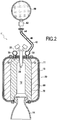
- the figure 2 schematically represents a rocket engine 1 'according to another embodiment of the disclosure.
- the fluid oxidant injected into the chamber 12 is a gaseous oxidizer.
- the liquid oxidant reservoir of the first embodiment is replaced by a reservoir 80 for storing the gaseous oxidant, and supplying the injection torus 32, and therefore the injectors 30, via a supply pipe 42, the pipe the reservoir 80 containing the gaseous oxidizer is pressurized, the pressurized gas flowing from the reservoir to the supply line 42 by the pressure vessel 32.
- a pressure reducer 82 the expander 82 being disposed downstream of the reservoir 80 and upstream of the supply pipe 42.
- the other elements of the rocket motor 1 ' are identical to those of the first embodiment, and will not be not described again.
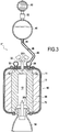
- the figure 3 schematically represents a rocket motor 1 "according to another embodiment of the disclosure
- the rocket motor 1 comprises a first igniter 20b, and a second igniter 20a.
- the first igniter 20b is disposed at the level of FIG. a portion of the wall 11 opposite the nozzle 14.
- the second solid propellant block 70 is arranged to cover the first igniter 20b, in the same way as the injectors 30. Therefore, the first igniter 20b does not it does not protrude into the inner enclosure 12, unlike the igniter 20 of the first embodiment, in other words, the second solid propellant unit 70 constitutes a thermal barrier for the first igniter 20b, protecting the latter from the gases during ignition of the engine 1 ".
- the second igniter 20a is disposed in the nozzle 14 and communicates with the cavity of the inner chamber 12 through the nozzle 14.
- the second igniter 20a is used to ignite the second block of solid propellant 70 and initiate the combustion of this latest. Pressure generated by the hot gases from the combustion of the second block of solid propellant 70 allows the ejection of the second igniter 20a out of the nozzle 14.
- the first igniter 20b makes it possible to ignite the first solid propellant block 60 and to initiate the combustion of the latter.
- the first igniter 20b is protected by the second solid propellant block 70 itself during the combustion of the latter.
- the first igniter 20b, as well as the injectors 30, are then discovered, and thus communicate with the internal enclosure 12.
- the first igniter 20b can not be damaged by the gases. hot from the combustion of the second block, and therefore retains its ignition capabilities for the first block.
- the other elements of the rocket motor 1 "are identical to those of the first embodiment, and will not be described again.
Landscapes
- Engineering & Computer Science (AREA)
- Chemical & Material Sciences (AREA)
- Combustion & Propulsion (AREA)
- Mechanical Engineering (AREA)
- General Engineering & Computer Science (AREA)
- Testing Of Engines (AREA)
- Fuel-Injection Apparatus (AREA)
- Combustion Methods Of Internal-Combustion Engines (AREA)
Abstract
Description
- Le présent exposé concerne le domaine des moteurs fusées, et plus précisément l'allumage et la propulsion des moteurs fusées, et un procédé d'utilisation de bloc de carburant pour de tels moteurs fusées.
- La propulsion des lanceurs spaciaux peut être effectuée par différents moyens. On connaît plusieurs types de moteurs fusées utilisant des techniques de propulsion différentes, notamment les moteurs à propergol solide, les moteurs à ergols liquides, et les moteurs à propulsion hybride.
- Les moteurs à propergol solide peuvent être facilement stockés, et permettent de produire une forte poussée. En revanche, ils ne sont pas rallumables et pas réutilisables, et la poussée ne peut pas être contrôlée. Les moteurs à ergols liquides permettent un rallumage du moteur et permettent la régulation de la poussée. Néanmoins, ils sont très couteux et nécessitent des moyens complexes de mise en oeuvre et de préparation au lancement. Dans les moteurs à propulsion hybride, la combustion du carburant solide est assurée par l'injection d'un oxydant liquide ou gazeux sous pression stocké dans un réservoir. Ils combinent des qualités des moteurs solides, telles que facilité et rapidité de mise en oeuvre, coût et niveau de poussée, à certaines qualités des moteurs liquide, comme la capacité de rallumage et de régulation de la poussée. Leur utilisation reste cependant limitée. En effet, ils ne permettent pas un allumage homogène et conduisent à des géométries internes complexes limitant le taux de chargement.
- Il existe un besoin pour un dispositif permettant de pallier les inconvénients cités ci-dessus, et permettant notamment un allumage homogène, une poussée élevée au décollage et une poussée de croisière contrôlable, tout en étant peu couteux et présentant une mise en oeuvre simple.
- Le présent exposé concerne un moteur fusée comprenant :
- une chambre de combustion débouchant sur une tuyère,
- au moins un bloc de propergol solide disposé dans la chambre de combustion, le bloc de propergol solide comprenant un carburant solide et un comburant solide,
- au moins un injecteur configuré pour injecter un comburant fluide dans la chambre de combustion,
- un organe de régulation pour réguler le débit d'injection de comburant fluide dans la chambre de combustion.
- Le bloc de propergol solide peut comporter un carburant sous la forme d'une phase polymérisée, dans laquelle un comburant sous la forme de grains solides se trouve. Le comburant, en d'autres termes l'oxydant, est configuré de telle sorte qu'après allumage à l'aide d'un allumeur, il réagisse chimiquement avec le carburant solide, entraînant la combustion du bloc de propergol solide. Le fait que le bloc de propergol solide comporte initialement, en plus d'un carburant solide, un comburant solide, permet de faciliter l'allumage en limitant la quantité d'énergie nécessaire à ce dernier, et d'uniformiser l'allumage du bloc sur toute sa surface. Par ailleurs, cela permet une meilleure réactivité et une meilleure stabilité vis-à-vis des variations de débit d'injection d'un comburant fluide.
- L'injecteur permet en outre d'injecter un comburant fluide dans la chambre de combustion. L'injection d'un comburant fluide, en plus du comburant solide déjà présent dans le bloc de propergol solide, permet d'intensifier la combustion du bloc, et ainsi d'augmenter le niveau de poussée du moteur. Plus précisément, l'organe de régulation permet de réguler le débit d'injection, et donc de réguler le niveau de poussée du moteur en fonction du débit d'injection du comburant fluide. Ainsi, à partir d'un niveau de poussée initial assuré par la présence du comburant solide dans le bloc de propergol solide, il est possible, en faisant varier le débit d'injection de comburant fluide, d'atteindre et de réguler la poussée du moteur de manière optimale suivant le profil souhaité de la mission. Par exemple, pour un étage inférieur, une forte poussée est nécessaire au décollage, une poussée réduite est nécessaire en phase atmosphérique pour limiter la pression dynamique maximum, et une régulation de la poussée est nécessaire pour permettre un retour avec atterrissage vertical. Par ailleurs, pour un étage supérieur, la précision de l'injection de la charge utile est accrue par rapport à un étage solide classique, grâce à la régulation de la poussée. Dans le cas d'une éjection d'un équipage en phase de décollage, cette régulation permet également d'assurer une forte poussée pour s'extraire du lanceur, puis un régime de croisière pour éloigner l'équipage.
- Dans certains modes de réalisation, le taux de comburant solide dans le bloc de propergol solide est déterminé de manière à ce que, après allumage du moteur, la combustion du bloc de propergol solide soit auto-entretenue sans injection supplémentaire de comburant fluide dans la chambre de combustion.
- En d'autres termes, le taux de comburant solide dans le bloc de propergol solide est supérieur à une valeur seuil permettant l'auto-entretien de la combustion du bloc de propergol après allumage, cette combustion pouvant se poursuivre sans apport supplémentaire nécessaire de comburant fluide. Cette configuration permet d'assurer une poussée de base du moteur, dont la valeur peut être augmentée et régulée par apport de comburant fluide par l'intermédiaire de l'injecteur et de l'organe de régulation.
- Dans certains modes de réalisation, le taux de comburant solide dans le bloc de propergol solide est déterminé de manière à ce que, après allumage du moteur, la combustion du bloc de propergol solide ne soit pas auto-entretenue sans injection supplémentaire de comburant fluide dans la chambre de combustion.
- En d'autres termes, le taux de comburant solide dans le bloc de propergol solide est inférieur à une valeur seuil permettant l'auto-entretien de la combustion du bloc de propergol après allumage, cette combustion ne pouvant pas se poursuivre sans apport supplémentaire de comburant fluide. Cette configuration permet de pouvoir arrêter la combustion, et donc la propulsion du moteur lorsque cela est souhaité ou nécessaire, avant que tout le bloc de propergol solide ne soit consumé. Par ailleurs cette configuration permet d'assurer un niveau de poussée minimal associé à un débit minimal de comburant fluide, dont l'augmentation et la variation de débit permet d'atteindre ou de réguler la poussée de manière optimale suivant le profil de mission.
- Dans certains modes de réalisation, ledit bloc de propergol solide forme un premier bloc, et comprend en outre :
- un deuxième bloc de propergol solide disposé dans la chambre de combustion de telle sorte à définir une cavité débouchant sur la tuyère,
- le premier bloc étant encapsulé entre une paroi interne de la chambre de combustion et le deuxième bloc de propergol solide.
- Par « encapsulé », on comprend que le deuxième bloc de propergol solide forme, avec la paroi interne de la chambre de combustion, un espace clos dans lequel se trouve le premier bloc de propergol solide. Ainsi, ce dernier est protégé par le deuxième bloc, de telle sorte que lorsque le deuxième se consume après allumage, le premier bloc n'est pas affecté par la combustion de deuxième bloc. En effet, le premier bloc ne se découvre que lorsque la combustion du deuxième bloc est terminée. Ainsi, le profil initial de la surface du premier bloc de propergol solide est préservé de l'agression due aux gaz chauds et érosifs du deuxième bloc.
- Dans certains modes de réalisation, le taux de comburant dans le deuxième bloc de propergol solide permet l'auto-entretien de la combustion, sans injection de comburant fluide. La présence du deuxième bloc permet ainsi d'assurer un niveau de poussée initial en fixant un taux de comburant solide dans le deuxième bloc, puis, lorsque la combustion du deuxième bloc est terminée, et que la combustion du premier bloc a débutée, de pouvoir réguler le niveau de poussée en fonction du débit d'injection de comburant fluide.
- Dans certains modes de réalisation, le taux de comburant solide dans le premier bloc de propergol solide est différent du taux de comburant solide dans le deuxième bloc de propergol solide.
- Par exemple, par l'adjonction d'un taux de comburant plus important dans le deuxième bloc de propergol solide que dans le premier bloc de propergol solide, il est possible d'assurer une poussée initiale importante, pouvant être nécessaire au décollage. Par ailleurs, par l'adjonction d'un taux de comburant solide dans le premier bloc inférieur au taux de comburant solide dans le deuxième bloc, il est possible, lorsque la combustion du deuxième bloc est terminée, et que la combustion du premier bloc a débutée, d'obtenir un niveau de poussée minimal pouvant être augmenté ou régulé en fonction du débit d'injection du comburant fluide.
- Dans certains modes de réalisation, le deuxième bloc de propergol solide est disposé de telle sorte à obturer le au moins un injecteur.
- En d'autres termes, le au moins un injecteur n'est découvert que lorsque la combustion du deuxième bloc de propergol solide est terminée. Ainsi, l'injecteur est protégé par le deuxième bloc de propergol solide lui-même pendant la combustion de ce dernier. Cela permet d'éviter une dégradation du ou des injecteurs provoquée par la combustion du deuxième bloc, et ainsi de conserver un état de fonctionnement approprié pour leur utilisation lors de la combustion du premier bloc.
- Dans certains modes de réalisation, le moteur fusée comporte un bouchon configuré pour empêcher des gaz de combustion du deuxième bloc de propergol solide de pénétrer dans l'injecteur, et pour être ouvert lorsqu'un comburant fluide est injecté à travers ledit injecteur.
- Ce bouchon est configuré de telle sorte à obturer hermétiquement l'injecteur, de manière à ce que les gaz de combustion issus de la combustion du deuxième bloc ne puisse pénétrer dans l'injecteur et se mélanger au comburant fluide présent en amont de l'injecteur, pouvant détériorer le dispositif, notamment entraîner une dégradation thermique par fusion et/ou combustion du matériau de l'injecteur, ou une inflammation de gaz combustibles dans le dôme d'injection en amont de l'injecteur par contact avec l'oxydant à faible pression. Par ailleurs, ce bouchon est configuré pour pouvoir être éjecté lorsqu'une pression est exercée en amont de ce dernier, par exemple lorsqu'un comburant fluide est injecté par l'injecteur.
- Dans certains modes de réalisation, le moteur fusée comporte un premier allumeur disposé dans la paroi de la chambre de combustion, le deuxième bloc de propergol solide étant disposé de telle sorte à recouvrir le premier allumeur, et un deuxième allumeur disposé dans la tuyère et communiquant avec la cavité à travers la tuyère.
- Le deuxième allumeur permet d'allumer le deuxième bloc de propergol solide et d'initier la combustion de ce dernier. De même, le premier allumeur permet d'allumer le premier bloc de propergol solide et d'initier la combustion de ce dernier. En outre, le premier allumeur étant protégé par le deuxième bloc de propergol solide lui-même pendant la combustion de ce dernier, le premier allumeur ne peut pas être détérioré par les gaz chauds issus de la combustion du deuxième bloc.
- Dans certains modes de réalisation, le deuxième allumeur est configuré pour être éjecté du moteur après allumage du deuxième bloc de propergol solide.
- Dans le cas où le deuxième bloc de propergol solide est configuré de telle sorte que sa combustion soit auto-entretenue, aucun rallumage de celui-ci ne sera nécessaire. Le deuxième allumeur permet donc uniquement l'allumage initial du deuxième bloc, et est configuré pour être éjecté après cet allumage, par l'intermédiaire de la pression exercée par les gaz chauds générés par la combustion par exemple. L'absence du deuxième allumeur dans la tuyère après son éjection permet en outre de ne pas perturber la poussée du moteur.
- Dans certains modes de réalisation, le moteur fusée comprend un canal d'alimentation configuré pour alimenter l'injecteur en comburant fluide sous forme liquide ou gazeuse, dans lequel le canal d'alimentation comporte un clapet anti-retour pour bloquer l'écoulement des gaz de combustion provenant de la chambre de combustion à travers le canal d'alimentation.
- Le clapet anti-retour n'est ouvert que lorsque du comburant fluide doit être injecté. Cela permet d'empêcher les gaz de combustion issu de la combustion du premier bloc de propergol solide de se mélanger au comburant fluide stocké en amont, lors de la combustion du premier bloc de propergol solide, dans la phase de régulation de la poussée du moteur.
- Dans certains modes de réalisation, le canal d'alimentation comporte une vanne de régulation disposée en amont du clapet antiretour, la vanne de régulation étant configurée pour réguler le débit d'injection de comburant fluide par l'injecteur.
- Par « amont », on comprend à l'opposé de la chambre de combustion par rapport au clapet antiretour. La vanne de régulation permet notamment d'augmenter ou de diminuer le débit d'injection de comburant fluide dans la chambre de combustion, et ainsi de réguler la poussée du moteur.
- Dans certains modes de réalisation, l'ouverture de la vanne de régulation est commandée par une unité de commande.
- L'unité de commande peut être un calculateur commandant l'ouverture de la vanne de régulation en fonction de mesures effectuées dans le moteur fusée, par exemple la pression dans la chambre de combustion.
- Le présent exposé concerne également un procédé d'utilisation d'un bloc de propergol solide comprenant un carburant solide et un comburant solide, le bloc de propergol solide étant disposé dans une chambre de combustion débouchant sur une tuyère, un comburant fluide étant injecté dans la chambre de combustion à un débit souhaité.
- Le bloc de propergol solide peut être utilisé dans un moteur fusée. La présence de comburant solide dans le bloc de propergol solide permet un allumage uniforme de celui-ci. Le comburant fluide peut être injecté par l'intermédiaire d'un injecteur débouchant dans la chambre de combustion. L'injection d'un comburant fluide, en plus du comburant solide déjà présent dans le bloc de propergol solide, permet d'intensifier la combustion du bloc, et ainsi d'augmenter le niveau de poussée du moteur.
- L'invention et ses avantages seront mieux compris à la lecture de la description détaillée faite ci-après de différents modes de réalisation de l'invention donnés à titre d'exemples non limitatifs. Cette description fait référence aux pages de figures annexées, sur lesquelles :
- la
figure 1 représente schématiquement une vue en coupe d'un moteur fusée selon un mode de réalisation. - la
figure 2 représente schématiquement une vue en coupe d'un moteur fusée selon un autre mode de réalisation. - la
figure 3 représente schématiquement une vue en coupe d'un moteur fusée selon encore un autre mode de réalisation. - Un moteur fusée selon le présent exposé va être décrit en référence aux
figures 1 à 3 . - La
figure 1 représente schématiquement un moteur fusée 1 selon un mode de réalisation de l'exposé. Le moteur fusée 1 comporte une chambre de combustion 10 comprenant une paroi 11 définissant une enceinte interne 12. Lors du fonctionnement du moteur, la combustion du carburant s'effectue dans l'enceinte interne 12 de la chambre de combustion 10. La chambre de combustion 10 comporte également une couche de protection thermique 13 sur la face interne de la paroi 11 de la chambre de combustion. Cette couche de protection thermique 13 peut comporter un élastomère du type polybutadiène déposé et polymérisé directement sur la face interne de la paroi 11. Cette protection thermique 13 peut également servir au collage du propergol à la paroi 11 et à la transmission optimale des efforts de pression à la paroi. La protection thermique 13 permet en outre de limiter les contraintes thermiques auxquelles la paroi 11 est soumise au cours et en fin de la combustion. - L'enceinte interne 12 débouche sur une tuyère 14, qui peut être orientable par rapport à la chambre de combustion 10.
- Le moteur 1 comporte en outre un allumeur 20, pouvant comporter par exemple une bougie d'allumage et une torche, permettant d'initier la combustion au sein de l'enceinte interne 12 de la chambre de combustion 10. L'allumeur 20 permet également le rallumage du moteur, lorsque la combustion est arrêtée temporairement. Dans ce mode de réalisation, l'allumeur 20 est disposé de manière à être positionné au moins en partie dans l'enceinte interne 12, en passant à travers la paroi 11 de la chambre de combustion via un orifice d'allumage 11a présent dans ladite paroi, faisant ainsi saillie dans l'enceinte interne 12.
- Par ailleurs, des injecteurs 30 sont également disposés au travers de la paroi 11 de la chambre de combustion 10, de manière à pouvoir injecter un comburant fluide dans l'enceinte interne 12. Les injecteurs 30 sont par exemple répartis autour de la partie de l'allumeur 20 faisant saillie dans l'enceinte interne 12, et sont alimentés en comburant fluide par un tore d'injection 32, disposé à l'extérieur de la chambre de combustion 10. En outre, l'extrémité des injecteurs 30 débouchant dans l'enceinte interne 12, est initialement obturée par des bouchons 33, empêchant un écoulement des gaz de combustion depuis la chambre de combustion 10 jusqu'au tore d'injection 32 lors du fonctionnement du moteur 1. Les bouchons 33 sont configurés pour pouvoir être éjectés lorsqu'une pression dépassant un seuil prédéterminé est exercée en amont de ces derniers, par exemple dans le tore d'injection 32.
- Un réservoir 40 permet de stocker le comburant fluide, et d'alimenter le tore d'injection 32, et donc les injecteurs 30 en comburant fluide, via une canalisation d'alimentation 42, la canalisation d'alimentation 42 étant en communication fluidique avec le réservoir 40 et le tore d'injection 32.
- Une vanne de régulation 44 est disposée dans la canalisation d'alimentation 42 en aval du réservoir, et un clapet antiretour 46 est disposé dans la canalisation d'alimentation 42 en aval de la vanne de régulation 44. Le terme « aval » est considéré suivant le sens d'écoulement du comburant fluide depuis le réservoir 40 jusqu'au tore d'injection 32. La vanne de régulation 44 permet de réguler le débit d'alimentation des injecteurs 30, en comburant fluide. Le clapet antiretour 46 permet l'écoulement du comburant fluide depuis le réservoir 40 jusqu'au tore d'injection 32, mais empêche l'écoulement du comburant fluide depuis le tore d'injection 32 jusqu'au réservoir 40. Le clapet antiretour 46 permet ainsi d'empêcher un retour des gaz de combustion depuis la chambre de combustion 10 jusqu'au réservoir 40 lors du fonctionnement du moteur 1.
- Dans le mode de réalisation illustré sur la
figure 1 , le comburant fluide utilisé est sous forme liquide, par exemple un ergol liquide. Le réservoir 40 contenant le comburant liquide est pressurisé à l'aide d'une sphère de gaz pressurisant 50 adjacente au réservoir 40 et connectée à celle-ci par l'intermédiaire d'un détendeur 52. La sphère de gaz pressurisant 50 permet de réguler la pression au sein du réservoir 40, par l'intermédiaire du détendeur 52. - Par ailleurs, dans cet exemple, le moteur fusée 1 comporte deux blocs de propergol solide disposés dans l'enceinte interne 12 de la chambre de combustion 10. Un premier bloc de propergol solide 60 présente une forme sensiblement annulaire, et est disposé contre la face interne de la paroi 11, la protection thermique 13 étant prise en sandwich entre cette dernière et le premier bloc de propergol solide 60.
- Un deuxième bloc de propergol solide 70 présente également une forme sensiblement annulaire, en étant plaqué contre le premier bloc de propergol solide 60. Le deuxième bloc de propergol solide 70 définit ainsi une cavité de l'enceinte interne 12 débouchant sur la tuyère 14. Par ailleurs, l'allumeur 20 fait saillie dans la cavité à travers le deuxième bloc de propergol solide 70. Bien que les blocs de propergol solide présentent une forme sensiblement annulaire dans cet exemple, d'autres formes peuvent être envisagées, comme c'est le cas en propulsion solide classique.
- Suivant cette configuration, le premier bloc de propergol solide 60 est disposé de telle sorte à être encapsulé entre la face interne de la paroi 11 et le deuxième bloc de propergol solide 70. En d'autres termes, aucune surface du premier bloc de propergol solide 60 ne communique avec l'enceinte interne 12. En outre, le deuxième bloc de propergol solide 70 est disposé de manière à recouvrir les injecteurs 30, ces derniers étant initialement noyés dans le bloc. En d'autres termes, le deuxième bloc de propergol solide 70 constitue une barrière thermique pour le premier bloc de propergol solide 60, ainsi que pour les injecteurs 30, protégeant ces derniers des gaz de combustion lors de l'allumage du moteur 1 et de la combustion du deuxième bloc de propergol 70.
- Le premier bloc de propergol solide 60 et le deuxième bloc de propergol solide 70 comportent un carburant solide et un comburant solide. Le carburant solide est sous la forme d'une phase polymérisée pouvant être du polybutadiène (PBHT), dans laquelle le comburant solide est sous la forme de grains solides répartis de manière uniforme dans la phase polymérisée.
- Le procédé de fabrication des blocs peut consister à couler les deux blocs 60 et 70 successivement, directement dans l'enceinte du propulseur revêtue de sa protection thermique, en changeant de noyau interne pour la deuxième coulée. L'avantage de cette méthode est de choisir un degré de polymérisation optimal de la protection thermique puis du premier bloc 60, afin de garantir une parfaite adhérence aux différentes interfaces. Une autre méthode de fabrication des blocs peut comporter une première étape consistant à couler le premier bloc de propergol solide 60 dans un premier moule, et une deuxième étape, après la polymérisation du premier bloc, consistant à couler le deuxième bloc de propergol solide 70 dans un deuxième moule, plus petit que le premier moule. De manière alternative, les blocs de propergol solide peuvent être fabriqués par fabrication additive.
- Le premier bloc de propergol solide 60 présente un taux de comburant solide, ou concentration en comburant solide, plus faible que celui du deuxième bloc de propergol solide 70. Dans cet exemple, le taux de comburant solide dans le deuxième bloc de propergol solide 70 est configuré de manière à ce que, après allumage du moteur par l'allumeur 20, la combustion du deuxième bloc de propergol solide 70 soit auto-entretenue, sans nécessité d'apport supplémentaire de comburant fluide. A l'inverse, le taux de comburant solide dans le premier bloc de propergol solide 60 est configuré de manière à ce que la combustion du premier bloc de propergol solide 60 ne soit pas auto-entretenue, et nécessite un apport supplémentaire de comburant fluide par les injecteurs 30.
- Un procédé d'utilisation des blocs de propergol solide va maintenant être décrit.
- L'allumeur 20 permet d'initier la combustion dans la chambre de combustion 10. La présence du comburant solide dans le deuxième bloc de propergol solide 70 permet un allumage uniforme de ce dernier. La présence de ce comburant solide en quantité importante permet en outre une poussée plus importante du moteur pour la phase d'allumage. Lorsque le deuxième bloc de propergol solide 70 est entièrement consumé, les injecteurs 30 sont alors découverts, et communiquent ainsi avec l'enceinte interne 12. Ils ont en outre pu être protégés des gaz de combustion pendant la combustion du deuxième bloc de propergol solide 70, en étant protégé par ce dernier. Par ailleurs, la présence des bouchons 33 empêchent les gaz de combustion de pénétrer dans les injecteurs 30, lorsque ces derniers se trouvent découverts.
- Le premier bloc de propergol solide 60 est ensuite allumé par l'allumeur 20, de la même façon que le deuxième bloc de propergol solide 70. Afin de pouvoir entretenir sa combustion, du comburant fluide est également injecté dans l'enceinte interne 12 par l'intermédiaire des injecteurs 30. Pour ce faire, la vanne de régulation 44 est actionnée par l'intermédiaire d'une unité de commande (non représentée) de manière à permettre l'écoulement du comburant liquide depuis le réservoir pressurisé 40 jusqu'aux injecteurs 30. La pression exercée par le comburant liquide dans les injecteurs 30 permet l'éjection des bouchons 33, et donc l'injection du comburant liquide dans l'enceinte 12. Ainsi, la vanne de régulation 44 permet de réguler le débit d'injection, et donc de réguler le niveau de poussée du moteur 1 en fonction du débit d'injection du comburant liquide. Ainsi, à partir d'un niveau de poussée initial assuré par la présence du comburant solide dans le premier bloc de propergol solide 60, il est possible, en faisant varier le débit d'injection de comburant fluide, d'atteindre et de réguler la poussée du moteur 1 de manière optimale suivant le profil souhaité de la mission.
- La
figure 2 représente schématiquement un moteur fusée 1' selon un autre mode de réalisation de l'exposé. Selon ce mode de réalisation, le comburant fluide injecté dans l'enceinte 12 est un comburant gazeux. Le réservoir de comburant liquide du premier mode de réalisation est remplacé par un réservoir 80 permettant de stocker le comburant gazeux, et d'alimenter le tore d'injection 32, et donc les injecteurs 30, via une canalisation d'alimentation 42, la canalisation d'alimentation 42 étant en communication fluidique avec le réservoir 80 et le tore d'injection 32. Le réservoir 80 contenant le comburant gazeux est pressurisé, le gaz pressurisé s'écoulant depuis le réservoir jusqu'à la canalisation d'alimentation 42 par l'intermédiaire d'un détendeur 82, le détendeur 82 étant disposé en aval du réservoir 80 et en amont de la canalisation d'alimentation 42. Les autres éléments du moteur fusée 1' sont identiques à ceux du premier mode de réalisation, et ne seront pas décrits à nouveau. - La
figure 3 représente schématiquement un moteur fusée 1" selon un autre mode de réalisation de l'exposé. Dans ce mode de réalisation, le moteur fusée 1 comporte un premier allumeur 20b, et un deuxième allumeur 20a. Le premier allumeur 20b est disposé au niveau d'une partie de la paroi 11 opposée à la tuyère 14. En outre, le deuxième bloc de propergol solide 70 est disposé de manière à recouvrir le premier allumeur 20b, de la même manière que les injecteurs 30. Par conséquent, le premier allumeur 20b ne fait pas saillie dans l'enceinte interne 12, contrairement à l'allumeur 20 du premier mode de réalisation. En d'autres termes, le deuxième bloc de propergol solide 70 constitue une barrière thermique pour le premier allumeur 20b, protégeant ces derniers des gaz de combustion lors de l'allumage du moteur 1". - Le deuxième allumeur 20a est disposé dans la tuyère 14 et communique avec la cavité de l'enceinte interne 12 à travers la tuyère 14. Le deuxième allumeur 20a permet d'allumer le deuxième bloc de propergol solide 70 et d'initier la combustion de ce dernier. La pression générée par les gaz chauds issue de la combustion du deuxième bloc de propergol solide 70 permet l'éjection du deuxième allumeur 20a hors de la tuyère 14.
- Le premier allumeur 20b permet d'allumer le premier bloc de propergol solide 60 et d'initier la combustion de ce dernier. En outre, le premier allumeur 20b est protégé par le deuxième bloc de propergol solide 70 lui-même pendant la combustion de ce dernier. Lorsque le deuxième bloc de propergol solide 70 est entièrement consumé, le premier allumeur 20b, ainsi que les injecteurs 30, sont alors découverts, et communiquent ainsi avec l'enceinte interne 12. Le premier allumeur 20b ne peut ainsi pas être détérioré par les gaz chauds issus de la combustion du deuxième bloc, et conserve donc ses capacités d'allumage pour le premier bloc. Les autres éléments du moteur fusée 1" sont identiques à ceux du premier mode de réalisation, et ne seront pas décrits à nouveau.
- Bien que la présente invention ait été décrite en se référant à des exemples de réalisation spécifiques, il est évident que des modifications et des changements peuvent être effectués sur ces exemples sans sortir de la portée générale de l'invention telle que définie par les revendications. En particulier, des caractéristiques individuelles des différents modes de réalisation illustrés/mentionnés peuvent être combinées dans des modes de réalisation additionnels. Par exemple, bien que le mode de réalisation présenté en référence à la
figure 3 est illustré avec un réservoir contenant un comburant liquide, ce mode de réalisation peut également s'appliquer au moteur illustré sur lafigure 2 , comportant un réservoir contenant du comburant gazeux. Par conséquent, la description et les dessins doivent être considérés dans un sens illustratif plutôt que restrictif. - Il est également évident que toutes les caractéristiques décrites en référence à un procédé sont transposables, seules ou en combinaison, à un dispositif, et inversement, toutes les caractéristiques décrites en référence à un dispositif sont transposables, seules ou en combinaison, à un procédé.
Claims (10)
- Moteur fusée (1) comprenant :- une chambre de combustion (10) débouchant sur une tuyère (14),- au moins un premier bloc de propergol solide (60) disposé dans la chambre de combustion (10), le premier bloc de propergol solide (60) comprenant un carburant solide et un comburant solide,- au moins un injecteur (30) configuré pour injecter un comburant fluide dans la chambre de combustion (10),- un organe de régulation (44) pour réguler le débit d'injection de comburant fluide dans la chambre de combustion (10),- un deuxième bloc de propergol solide (70) disposé dans la chambre de combustion (10) de telle sorte à définir une cavité (12) débouchant sur la tuyère (14), le premier bloc (60) étant encapsulé entre une paroi interne de la chambre de combustion (10) et le deuxième bloc de propergol solide (70), le premier bloc de propergol solide (60) présentant un taux de comburant solide plus faible que celui du deuxième bloc de propergol solide (70).
- Moteur fusée (1) selon la revendication 1, dans lequel le taux de comburant solide dans le deuxième bloc de propergol solide (70) est déterminé de manière à ce que, après allumage du moteur (1), la combustion du deuxième bloc de propergol solide (70) soit auto-entretenue sans injection supplémentaire de comburant fluide dans la chambre de combustion (10).
- Moteur fusée (1) selon la revendication 1, dans lequel le taux de comburant solide dans le deuxième bloc de propergol solide (70) est déterminé de manière à ce que, après allumage du moteur (1), la combustion du deuxième bloc de propergol solide (70) ne soit pas auto-entretenue sans injection supplémentaire de comburant fluide dans la chambre de combustion (10).
- Moteur fusée (1) selon l'une quelconque des revendications 1 à 3, dans lequel le deuxième bloc de propergol solide (60) est disposé de telle sorte à obturer le au moins un injecteur (30).
- Moteur fusée (1) selon l'une quelconque des revendications 1 à 4, comportant un bouchon (33) configuré pour empêcher des gaz de combustion du deuxième bloc de propergol solide (70) de pénétrer dans l'injecteur (30), et pour être ouvert lorsqu'un comburant fluide est injecté à travers ledit injecteur (30).
- Moteur fusée (1) selon l'une quelconque des revendications 1 à 5, comportant un premier allumeur (20a) disposé dans la paroi (11) de la chambre de combustion (10), le deuxième bloc de propergol solide (70) étant disposé de telle sorte à recouvrir le premier allumeur (20a), et un deuxième allumeur (20b) disposé dans la tuyère (14) et communiquant avec la cavité (12) à travers la tuyère (14).
- Moteur fusée (1) selon la revendication 6, dans lequel le deuxième allumeur (20b) est configuré pour être éjecté du moteur (1) après allumage du deuxième bloc de propergol solide (70).
- Moteur fusée (1) selon l'une quelconque des revendications précédentes, comprenant un canal d'alimentation (42) configuré pour alimenter l'injecteur (30) en comburant fluide sous forme liquide ou gazeuse, dans lequel le canal d'alimentation (42) comporte un clapet anti-retour (46) pour bloquer l'écoulement des gaz de combustion provenant de la chambre de combustion (10) à travers le canal d'alimentation (42).
- Moteur fusée (1) selon la revendication 8, dans lequel le canal d'alimentation (42) comporte une vanne de régulation (44) disposée en amont du clapet anti-retour (46), la vanne de régulation (44) étant configurée pour réguler le débit d'injection de comburant fluide par l'injecteur (30).
- Procédé d'utilisation d'un bloc de propergol solide comprenant un carburant solide et un comburant solide, le bloc de propergol solide étant un premier bloc (60) et étant disposé dans une chambre de combustion (10) débouchant sur une tuyère (14), un deuxième bloc de propergol solide (70) étant disposé dans la chambre de combustion (10) de telle sorte à définir une cavité (12) débouchant sur la tuyère (14), le premier bloc (60) étant encapsulé entre une paroi interne de la chambre de combustion (10) et le deuxième bloc de propergol solide (70), le premier bloc de propergol solide (60) présentant un taux de comburant solide plus faible que celui du deuxième bloc de propergol solide (70), et un comburant fluide étant injecté dans la chambre de combustion (10) à un débit souhaité.
Applications Claiming Priority (1)
| Application Number | Priority Date | Filing Date | Title |
|---|---|---|---|
| FR1854088A FR3081190B1 (fr) | 2018-05-16 | 2018-05-16 | Moteur fusee solide-hybride ameliore |
Publications (2)
| Publication Number | Publication Date |
|---|---|
| EP3569858A1 true EP3569858A1 (fr) | 2019-11-20 |
| EP3569858B1 EP3569858B1 (fr) | 2021-06-23 |
Family
ID=63722483
Family Applications (1)
| Application Number | Title | Priority Date | Filing Date |
|---|---|---|---|
| EP19173808.7A Active EP3569858B1 (fr) | 2018-05-16 | 2019-05-10 | Moteur fusée solide-hybride amélioré |
Country Status (3)
| Country | Link |
|---|---|
| EP (1) | EP3569858B1 (fr) |
| ES (1) | ES2891398T3 (fr) |
| FR (1) | FR3081190B1 (fr) |
Citations (3)
| Publication number | Priority date | Publication date | Assignee | Title |
|---|---|---|---|---|
| US3286471A (en) * | 1963-09-30 | 1966-11-22 | North American Aviation Inc | Solid propellant rocket motor |
| US6016652A (en) * | 1994-10-21 | 2000-01-25 | Hy-Pat Corporation | Hybrid rocket system with disposable cartridge |
| US20090217525A1 (en) * | 2008-02-28 | 2009-09-03 | Fuller Jerome K | Stereolithographic rocket motor manufacturing method |
-
2018
- 2018-05-16 FR FR1854088A patent/FR3081190B1/fr active Active
-
2019
- 2019-05-10 ES ES19173808T patent/ES2891398T3/es active Active
- 2019-05-10 EP EP19173808.7A patent/EP3569858B1/fr active Active
Patent Citations (3)
| Publication number | Priority date | Publication date | Assignee | Title |
|---|---|---|---|---|
| US3286471A (en) * | 1963-09-30 | 1966-11-22 | North American Aviation Inc | Solid propellant rocket motor |
| US6016652A (en) * | 1994-10-21 | 2000-01-25 | Hy-Pat Corporation | Hybrid rocket system with disposable cartridge |
| US20090217525A1 (en) * | 2008-02-28 | 2009-09-03 | Fuller Jerome K | Stereolithographic rocket motor manufacturing method |
Also Published As
| Publication number | Publication date |
|---|---|
| FR3081190B1 (fr) | 2020-11-20 |
| EP3569858B1 (fr) | 2021-06-23 |
| FR3081190A1 (fr) | 2019-11-22 |
| ES2891398T3 (es) | 2022-01-27 |
Similar Documents
| Publication | Publication Date | Title |
|---|---|---|
| EP1965056B1 (fr) | Procédé pour le démarrage d'un moteur d'hélicoptère à turbine à gaz, circuit d'alimentation en carburant d'un tel moteur, et moteur ayant un tel circuit | |
| FR3042543B1 (fr) | Torche d'allumage pour moteur fusee | |
| CA2886564A1 (fr) | Injecteur a double circuit de chambre de combustion de turbomachine | |
| EP2142788B1 (fr) | Procédé et dispositif pour alimenter un moteur de propulsion spatiale en ergols cryogéniques liquides | |
| EP2885525B1 (fr) | Allumeur bimodal et procede d'injection bimodale pour allumeur de moteur-fusee | |
| EP2864620B1 (fr) | Turbopompe | |
| EP3569858B1 (fr) | Moteur fusée solide-hybride amélioré | |
| EP3147490B1 (fr) | Système de propulsion d'une fusée | |
| FR2618528A1 (fr) | Perfectionnements aux chambres de combustion auxiliaires, pour moteurs a combustion interne suralimentes, et moteurs a combustion interne equipes d'une telle chambre | |
| WO1995012067A1 (fr) | Dispositif d'injection de combustible liquide pour moteur diesel, et moteur diesel comprenant ce dispositif | |
| FR2617911A1 (fr) | Bloc de poudre de propergol solide et generateur de gaz | |
| EP2895726B1 (fr) | Dispositif de propulsion hybride anaérobie à carburant présente sous forme de solides divisés | |
| EP3835569B1 (fr) | Dispositif d'allumage pour moteur-fusée | |
| EP1346141B1 (fr) | Dispositif et methode d'injection d'un carburant gazeux sous forme liquide pour moteur a combustion interne | |
| EP0090739B1 (fr) | Système d'injection électromagnétique pour moteur Diesel donnant lieu à une loi d'injection de type "pression-temps" | |
| EP3207224A1 (fr) | Systeme d'allumage d'une chambre de combustion d'un turbomoteur | |
| FR2775499A1 (fr) | Moteur mixte susceptible de mettre en oeuvre au moins un mode statoreacteur et un mode superstatoreacteur | |
| FR3071550A1 (fr) | Chambre annulaire de combustion | |
| FR2768465A1 (fr) | Circuit d'injection de carburant pour un moteur a combustion interne et a injection directe | |
| EP2740635B1 (fr) | Générateur de gaz | |
| FR3137135A1 (fr) | Dispositif d'injection et procédé d'injection d'une combinaison de carburant liquide-liquide dans un espace de combustion | |
| FR3111669A1 (fr) | Injecteur multipoint pour une chambre de combustion de turbomachine. | |
| BE365395A (fr) | ||
| CH334075A (fr) | Propulseur à réaction | |
| WO2018134517A1 (fr) | Dispositif et procede d'injection d'une charge dans la chambre de combustion d'un moteur a combustion interne et a allumage commande |
Legal Events
| Date | Code | Title | Description |
|---|---|---|---|
| PUAI | Public reference made under article 153(3) epc to a published international application that has entered the european phase |
Free format text: ORIGINAL CODE: 0009012 |
|
| STAA | Information on the status of an ep patent application or granted ep patent |
Free format text: STATUS: REQUEST FOR EXAMINATION WAS MADE |
|
| 17P | Request for examination filed |
Effective date: 20190513 |
|
| AK | Designated contracting states |
Kind code of ref document: A1 Designated state(s): AL AT BE BG CH CY CZ DE DK EE ES FI FR GB GR HR HU IE IS IT LI LT LU LV MC MK MT NL NO PL PT RO RS SE SI SK SM TR |
|
| AX | Request for extension of the european patent |
Extension state: BA ME |
|
| GRAP | Despatch of communication of intention to grant a patent |
Free format text: ORIGINAL CODE: EPIDOSNIGR1 |
|
| STAA | Information on the status of an ep patent application or granted ep patent |
Free format text: STATUS: GRANT OF PATENT IS INTENDED |
|
| RIC1 | Information provided on ipc code assigned before grant |
Ipc: F02K 9/94 20060101ALI20201216BHEP Ipc: F02K 9/72 20060101AFI20201216BHEP |
|
| INTG | Intention to grant announced |
Effective date: 20210120 |
|
| GRAS | Grant fee paid |
Free format text: ORIGINAL CODE: EPIDOSNIGR3 |
|
| GRAA | (expected) grant |
Free format text: ORIGINAL CODE: 0009210 |
|
| STAA | Information on the status of an ep patent application or granted ep patent |
Free format text: STATUS: THE PATENT HAS BEEN GRANTED |
|
| AK | Designated contracting states |
Kind code of ref document: B1 Designated state(s): AL AT BE BG CH CY CZ DE DK EE ES FI FR GB GR HR HU IE IS IT LI LT LU LV MC MK MT NL NO PL PT RO RS SE SI SK SM TR |
|
| REG | Reference to a national code |
Ref country code: GB Ref legal event code: FG4D Free format text: NOT ENGLISH |
|
| REG | Reference to a national code |
Ref country code: CH Ref legal event code: EP |
|
| REG | Reference to a national code |
Ref country code: DE Ref legal event code: R096 Ref document number: 602019005494 Country of ref document: DE Ref country code: AT Ref legal event code: REF Ref document number: 1404519 Country of ref document: AT Kind code of ref document: T Effective date: 20210715 |
|
| REG | Reference to a national code |
Ref country code: IE Ref legal event code: FG4D Free format text: LANGUAGE OF EP DOCUMENT: FRENCH |
|
| REG | Reference to a national code |
Ref country code: LT Ref legal event code: MG9D |
|
| REG | Reference to a national code |
Ref country code: SE Ref legal event code: TRGR |
|
| PG25 | Lapsed in a contracting state [announced via postgrant information from national office to epo] |
Ref country code: BG Free format text: LAPSE BECAUSE OF FAILURE TO SUBMIT A TRANSLATION OF THE DESCRIPTION OR TO PAY THE FEE WITHIN THE PRESCRIBED TIME-LIMIT Effective date: 20210923 Ref country code: HR Free format text: LAPSE BECAUSE OF FAILURE TO SUBMIT A TRANSLATION OF THE DESCRIPTION OR TO PAY THE FEE WITHIN THE PRESCRIBED TIME-LIMIT Effective date: 20210623 Ref country code: LT Free format text: LAPSE BECAUSE OF FAILURE TO SUBMIT A TRANSLATION OF THE DESCRIPTION OR TO PAY THE FEE WITHIN THE PRESCRIBED TIME-LIMIT Effective date: 20210623 Ref country code: FI Free format text: LAPSE BECAUSE OF FAILURE TO SUBMIT A TRANSLATION OF THE DESCRIPTION OR TO PAY THE FEE WITHIN THE PRESCRIBED TIME-LIMIT Effective date: 20210623 |
|
| REG | Reference to a national code |
Ref country code: AT Ref legal event code: MK05 Ref document number: 1404519 Country of ref document: AT Kind code of ref document: T Effective date: 20210623 |
|
| PG25 | Lapsed in a contracting state [announced via postgrant information from national office to epo] |
Ref country code: LV Free format text: LAPSE BECAUSE OF FAILURE TO SUBMIT A TRANSLATION OF THE DESCRIPTION OR TO PAY THE FEE WITHIN THE PRESCRIBED TIME-LIMIT Effective date: 20210623 Ref country code: NO Free format text: LAPSE BECAUSE OF FAILURE TO SUBMIT A TRANSLATION OF THE DESCRIPTION OR TO PAY THE FEE WITHIN THE PRESCRIBED TIME-LIMIT Effective date: 20210923 Ref country code: RS Free format text: LAPSE BECAUSE OF FAILURE TO SUBMIT A TRANSLATION OF THE DESCRIPTION OR TO PAY THE FEE WITHIN THE PRESCRIBED TIME-LIMIT Effective date: 20210623 Ref country code: GR Free format text: LAPSE BECAUSE OF FAILURE TO SUBMIT A TRANSLATION OF THE DESCRIPTION OR TO PAY THE FEE WITHIN THE PRESCRIBED TIME-LIMIT Effective date: 20210924 |
|
| REG | Reference to a national code |
Ref country code: NL Ref legal event code: MP Effective date: 20210623 |
|
| RAP4 | Party data changed (patent owner data changed or rights of a patent transferred) |
Owner name: ARIANEGROUP SAS |
|
| REG | Reference to a national code |
Ref country code: ES Ref legal event code: FG2A Ref document number: 2891398 Country of ref document: ES Kind code of ref document: T3 Effective date: 20220127 |
|
| PG25 | Lapsed in a contracting state [announced via postgrant information from national office to epo] |
Ref country code: SM Free format text: LAPSE BECAUSE OF FAILURE TO SUBMIT A TRANSLATION OF THE DESCRIPTION OR TO PAY THE FEE WITHIN THE PRESCRIBED TIME-LIMIT Effective date: 20210623 Ref country code: PT Free format text: LAPSE BECAUSE OF FAILURE TO SUBMIT A TRANSLATION OF THE DESCRIPTION OR TO PAY THE FEE WITHIN THE PRESCRIBED TIME-LIMIT Effective date: 20211025 Ref country code: RO Free format text: LAPSE BECAUSE OF FAILURE TO SUBMIT A TRANSLATION OF THE DESCRIPTION OR TO PAY THE FEE WITHIN THE PRESCRIBED TIME-LIMIT Effective date: 20210623 Ref country code: NL Free format text: LAPSE BECAUSE OF FAILURE TO SUBMIT A TRANSLATION OF THE DESCRIPTION OR TO PAY THE FEE WITHIN THE PRESCRIBED TIME-LIMIT Effective date: 20210623 Ref country code: CZ Free format text: LAPSE BECAUSE OF FAILURE TO SUBMIT A TRANSLATION OF THE DESCRIPTION OR TO PAY THE FEE WITHIN THE PRESCRIBED TIME-LIMIT Effective date: 20210623 Ref country code: AT Free format text: LAPSE BECAUSE OF FAILURE TO SUBMIT A TRANSLATION OF THE DESCRIPTION OR TO PAY THE FEE WITHIN THE PRESCRIBED TIME-LIMIT Effective date: 20210623 Ref country code: SK Free format text: LAPSE BECAUSE OF FAILURE TO SUBMIT A TRANSLATION OF THE DESCRIPTION OR TO PAY THE FEE WITHIN THE PRESCRIBED TIME-LIMIT Effective date: 20210623 Ref country code: EE Free format text: LAPSE BECAUSE OF FAILURE TO SUBMIT A TRANSLATION OF THE DESCRIPTION OR TO PAY THE FEE WITHIN THE PRESCRIBED TIME-LIMIT Effective date: 20210623 |
|
| PG25 | Lapsed in a contracting state [announced via postgrant information from national office to epo] |
Ref country code: PL Free format text: LAPSE BECAUSE OF FAILURE TO SUBMIT A TRANSLATION OF THE DESCRIPTION OR TO PAY THE FEE WITHIN THE PRESCRIBED TIME-LIMIT Effective date: 20210623 |
|
| REG | Reference to a national code |
Ref country code: DE Ref legal event code: R097 Ref document number: 602019005494 Country of ref document: DE |
|
| PG25 | Lapsed in a contracting state [announced via postgrant information from national office to epo] |
Ref country code: DK Free format text: LAPSE BECAUSE OF FAILURE TO SUBMIT A TRANSLATION OF THE DESCRIPTION OR TO PAY THE FEE WITHIN THE PRESCRIBED TIME-LIMIT Effective date: 20210623 |
|
| PLBE | No opposition filed within time limit |
Free format text: ORIGINAL CODE: 0009261 |
|
| STAA | Information on the status of an ep patent application or granted ep patent |
Free format text: STATUS: NO OPPOSITION FILED WITHIN TIME LIMIT |
|
| 26N | No opposition filed |
Effective date: 20220324 |
|
| PG25 | Lapsed in a contracting state [announced via postgrant information from national office to epo] |
Ref country code: AL Free format text: LAPSE BECAUSE OF FAILURE TO SUBMIT A TRANSLATION OF THE DESCRIPTION OR TO PAY THE FEE WITHIN THE PRESCRIBED TIME-LIMIT Effective date: 20210623 |
|
| REG | Reference to a national code |
Ref country code: CH Ref legal event code: PL |
|
| REG | Reference to a national code |
Ref country code: BE Ref legal event code: MM Effective date: 20220531 |
|
| PG25 | Lapsed in a contracting state [announced via postgrant information from national office to epo] |
Ref country code: MC Free format text: LAPSE BECAUSE OF FAILURE TO SUBMIT A TRANSLATION OF THE DESCRIPTION OR TO PAY THE FEE WITHIN THE PRESCRIBED TIME-LIMIT Effective date: 20210623 Ref country code: LU Free format text: LAPSE BECAUSE OF NON-PAYMENT OF DUE FEES Effective date: 20220510 Ref country code: LI Free format text: LAPSE BECAUSE OF NON-PAYMENT OF DUE FEES Effective date: 20220531 Ref country code: CH Free format text: LAPSE BECAUSE OF NON-PAYMENT OF DUE FEES Effective date: 20220531 |
|
| REG | Reference to a national code |
Ref country code: DE Ref legal event code: R082 Ref document number: 602019005494 Country of ref document: DE Representative=s name: CBDL PATENTANWAELTE GBR, DE Ref country code: DE Ref legal event code: R082 Ref document number: 602019005494 Country of ref document: DE Representative=s name: CBDL PATENTANWAELTE EGBR, DE |
|
| PG25 | Lapsed in a contracting state [announced via postgrant information from national office to epo] |
Ref country code: IE Free format text: LAPSE BECAUSE OF NON-PAYMENT OF DUE FEES Effective date: 20220510 |
|
| PG25 | Lapsed in a contracting state [announced via postgrant information from national office to epo] |
Ref country code: BE Free format text: LAPSE BECAUSE OF NON-PAYMENT OF DUE FEES Effective date: 20220531 |
|
| P01 | Opt-out of the competence of the unified patent court (upc) registered |
Effective date: 20230612 |
|
| PG25 | Lapsed in a contracting state [announced via postgrant information from national office to epo] |
Ref country code: HU Free format text: LAPSE BECAUSE OF FAILURE TO SUBMIT A TRANSLATION OF THE DESCRIPTION OR TO PAY THE FEE WITHIN THE PRESCRIBED TIME-LIMIT; INVALID AB INITIO Effective date: 20190510 |
|
| PG25 | Lapsed in a contracting state [announced via postgrant information from national office to epo] |
Ref country code: MK Free format text: LAPSE BECAUSE OF FAILURE TO SUBMIT A TRANSLATION OF THE DESCRIPTION OR TO PAY THE FEE WITHIN THE PRESCRIBED TIME-LIMIT Effective date: 20210623 Ref country code: CY Free format text: LAPSE BECAUSE OF FAILURE TO SUBMIT A TRANSLATION OF THE DESCRIPTION OR TO PAY THE FEE WITHIN THE PRESCRIBED TIME-LIMIT Effective date: 20210623 |
|
| PG25 | Lapsed in a contracting state [announced via postgrant information from national office to epo] |
Ref country code: MT Free format text: LAPSE BECAUSE OF FAILURE TO SUBMIT A TRANSLATION OF THE DESCRIPTION OR TO PAY THE FEE WITHIN THE PRESCRIBED TIME-LIMIT Effective date: 20210623 |
|
| PGFP | Annual fee paid to national office [announced via postgrant information from national office to epo] |
Ref country code: DE Payment date: 20250521 Year of fee payment: 7 |
|
| PGFP | Annual fee paid to national office [announced via postgrant information from national office to epo] |
Ref country code: IT Payment date: 20250527 Year of fee payment: 7 |
|
| PGFP | Annual fee paid to national office [announced via postgrant information from national office to epo] |
Ref country code: FR Payment date: 20250528 Year of fee payment: 7 |
|
| PGFP | Annual fee paid to national office [announced via postgrant information from national office to epo] |
Ref country code: SE Payment date: 20250521 Year of fee payment: 7 |
|
| PGFP | Annual fee paid to national office [announced via postgrant information from national office to epo] |
Ref country code: ES Payment date: 20250630 Year of fee payment: 7 |
|
| PG25 | Lapsed in a contracting state [announced via postgrant information from national office to epo] |
Ref country code: TR Free format text: LAPSE BECAUSE OF FAILURE TO SUBMIT A TRANSLATION OF THE DESCRIPTION OR TO PAY THE FEE WITHIN THE PRESCRIBED TIME-LIMIT Effective date: 20210623 |
|
| PGFP | Annual fee paid to national office [announced via postgrant information from national office to epo] |
Ref country code: GB Payment date: 20260306 Year of fee payment: 8 |