EP3569776A1 - Apparatus for controlling and method for controlling quick-clamp of construction machine - Google Patents
Apparatus for controlling and method for controlling quick-clamp of construction machine Download PDFInfo
- Publication number
- EP3569776A1 EP3569776A1 EP18741897.5A EP18741897A EP3569776A1 EP 3569776 A1 EP3569776 A1 EP 3569776A1 EP 18741897 A EP18741897 A EP 18741897A EP 3569776 A1 EP3569776 A1 EP 3569776A1
- Authority
- EP
- European Patent Office
- Prior art keywords
- input unit
- clamp
- signal
- controller
- input
- Prior art date
- Legal status (The legal status is an assumption and is not a legal conclusion. Google has not performed a legal analysis and makes no representation as to the accuracy of the status listed.)
- Granted
Links
Images

Classifications
-
- E—FIXED CONSTRUCTIONS
- E02—HYDRAULIC ENGINEERING; FOUNDATIONS; SOIL SHIFTING
- E02F—DREDGING; SOIL-SHIFTING
- E02F9/00—Component parts of dredgers or soil-shifting machines, not restricted to one of the kinds covered by groups E02F3/00 - E02F7/00
- E02F9/20—Drives; Control devices
- E02F9/2004—Control mechanisms, e.g. control levers
- E02F9/2012—Setting the functions of the control levers, e.g. changing assigned functions among operations levers, setting functions dependent on the operator or seat orientation
-
- E—FIXED CONSTRUCTIONS
- E02—HYDRAULIC ENGINEERING; FOUNDATIONS; SOIL SHIFTING
- E02F—DREDGING; SOIL-SHIFTING
- E02F3/00—Dredgers; Soil-shifting machines
- E02F3/04—Dredgers; Soil-shifting machines mechanically-driven
- E02F3/64—Buckets cars, i.e. having scraper bowls
- E02F3/65—Component parts, e.g. drives, control devices
- E02F3/653—Connection mechanisms to the main body of the machine
-
- E—FIXED CONSTRUCTIONS
- E02—HYDRAULIC ENGINEERING; FOUNDATIONS; SOIL SHIFTING
- E02F—DREDGING; SOIL-SHIFTING
- E02F3/00—Dredgers; Soil-shifting machines
- E02F3/04—Dredgers; Soil-shifting machines mechanically-driven
- E02F3/28—Dredgers; Soil-shifting machines mechanically-driven with digging tools mounted on a dipper- or bucket-arm, i.e. there is either one arm or a pair of arms, e.g. dippers, buckets
- E02F3/36—Component parts
- E02F3/3604—Devices to connect tools to arms, booms or the like
-
- E—FIXED CONSTRUCTIONS
- E02—HYDRAULIC ENGINEERING; FOUNDATIONS; SOIL SHIFTING
- E02F—DREDGING; SOIL-SHIFTING
- E02F3/00—Dredgers; Soil-shifting machines
- E02F3/04—Dredgers; Soil-shifting machines mechanically-driven
- E02F3/28—Dredgers; Soil-shifting machines mechanically-driven with digging tools mounted on a dipper- or bucket-arm, i.e. there is either one arm or a pair of arms, e.g. dippers, buckets
- E02F3/36—Component parts
- E02F3/3604—Devices to connect tools to arms, booms or the like
- E02F3/3609—Devices to connect tools to arms, booms or the like of the quick acting type, e.g. controlled from the operator seat
- E02F3/3663—Devices to connect tools to arms, booms or the like of the quick acting type, e.g. controlled from the operator seat hydraulically-operated
-
- E—FIXED CONSTRUCTIONS
- E02—HYDRAULIC ENGINEERING; FOUNDATIONS; SOIL SHIFTING
- E02F—DREDGING; SOIL-SHIFTING
- E02F9/00—Component parts of dredgers or soil-shifting machines, not restricted to one of the kinds covered by groups E02F3/00 - E02F7/00
- E02F9/20—Drives; Control devices
- E02F9/2004—Control mechanisms, e.g. control levers
-
- E—FIXED CONSTRUCTIONS
- E02—HYDRAULIC ENGINEERING; FOUNDATIONS; SOIL SHIFTING
- E02F—DREDGING; SOIL-SHIFTING
- E02F9/00—Component parts of dredgers or soil-shifting machines, not restricted to one of the kinds covered by groups E02F3/00 - E02F7/00
- E02F9/20—Drives; Control devices
- E02F9/22—Hydraulic or pneumatic drives
- E02F9/2221—Control of flow rate; Load sensing arrangements
- E02F9/2225—Control of flow rate; Load sensing arrangements using pressure-compensating valves
- E02F9/2228—Control of flow rate; Load sensing arrangements using pressure-compensating valves including an electronic controller
-
- E—FIXED CONSTRUCTIONS
- E02—HYDRAULIC ENGINEERING; FOUNDATIONS; SOIL SHIFTING
- E02F—DREDGING; SOIL-SHIFTING
- E02F9/00—Component parts of dredgers or soil-shifting machines, not restricted to one of the kinds covered by groups E02F3/00 - E02F7/00
- E02F9/24—Safety devices, e.g. for preventing overload
-
- E—FIXED CONSTRUCTIONS
- E02—HYDRAULIC ENGINEERING; FOUNDATIONS; SOIL SHIFTING
- E02F—DREDGING; SOIL-SHIFTING
- E02F9/00—Component parts of dredgers or soil-shifting machines, not restricted to one of the kinds covered by groups E02F3/00 - E02F7/00
- E02F9/26—Indicating devices
-
- G—PHYSICS
- G08—SIGNALLING
- G08B—SIGNALLING SYSTEMS, e.g. PERSONAL CALLING SYSTEMS; ORDER TELEGRAPHS; ALARM SYSTEMS
- G08B3/00—Audible signalling systems, e.g. audible personal calling systems
- G08B3/10—Audible signalling systems, e.g. audible personal calling systems using electric transmission; using electromagnetic transmission
-
- E—FIXED CONSTRUCTIONS
- E02—HYDRAULIC ENGINEERING; FOUNDATIONS; SOIL SHIFTING
- E02F—DREDGING; SOIL-SHIFTING
- E02F9/00—Component parts of dredgers or soil-shifting machines, not restricted to one of the kinds covered by groups E02F3/00 - E02F7/00
- E02F9/26—Indicating devices
- E02F9/264—Sensors and their calibration for indicating the position of the work tool
- E02F9/265—Sensors and their calibration for indicating the position of the work tool with follow-up actions (e.g. control signals sent to actuate the work tool)
Definitions
- Embodiments of the present invention relate to an apparatus for controlling and a method for controlling quick clamping of construction machine.
- heavy machiney e.g., excavators
- excavators used in construction site or civil engineering works
- various replaceable attachments for multiple uses, for example, digging the ground using a bucket, dismantling concrete buildings and cutting rebar using a crusher, breaking rock and concrete using a breaker, transporting scrap iron and rock using a grab, foundation works for a vertical shaft, water supply, and sewage system using a clamshell bucket.
- the attachment is detachably coupled to an arm or a boom of the excavator to be replaceable according to the usage of the operation.
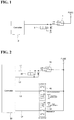
- FIG. 1 is an exemplary circuit diagram for performing a quick clamping function of conventional heavy machine.
- a machine control apparatus 2 activates a clamp solenoid valve 3 to perform a function of releasing an attachment, when a toggle switch 1 is switched on.
- Embodiments of the present invention may be directed to an apparatus for controlling quick clamping of construction machine that may substantially prevent an accident that may occur when an operator operates the control apparatus unintentionally and the attachment is released.
- embodiments of the present invention may further be directed to an apparatus for controlling quick clamping of construction machine that is realized by using a switch or an input button which is a conventionally provided element, instead of additionally providing a separate switch.
- an apparatus for controlling quick clamping of construction machine which comprises a clamp for mounting an attachment includes: a selection input unit for generating a selection signal during an on operation by an operator; an operation input unit for generating an operation signal during an operation by the operator; a clamp driving unit for releasing and fastening the clamp; and a controllercontroller for controlling the clamp driving unit to release the clamp while the operation signal is input after the selection signal is input.
- the operation input unit may generate the operation signal while the operator holds a pressing operation, and the controllercontroller may control the clamp driving unit so that the clamp is in a released state while input of the operation signal continues.
- the operation input unit may include a plurality of operation input units so that the operator operates the operation input unit using both hands simultaneously.
- the operation input unit may include one of a plurality of operation buttons and switches provided at a left joystick, and one of a plurality of operation buttons and switches provided at a right joystick.
- the controllercontroller may control the clamp driving unit to fasten the clamp.
- the apparatus may further include an output unit for outputting at least one of an alarm message and a warning sound.
- the controller may control the output unit to output at least one of the alarm message and the alarm sound.
- the controller may control the output unit to stop outputting the warning sound.
- the controller may activate a specific function mode controlled by the signal generated from the operation input unit.
- the controller may deactivate the specific function mode controlled by the signal generated from the operation input unit.
- the operation input unit may include one of a plurality of operation buttons and switches provided at a left joystick and one of a plurality of operation buttons and switches provided at a right joystick, and require simultaneous operation of both hands of the operator.
- the specific function of the selected operation button of the left joystick may be an engine deceleration selection signal output, and the specific function of the selected operation button of the right joystick may be a pressure-up selection signal output.
- the controller may monitor input of a pilot cutoff signal, and controls the clamp driving unit so that the clamp is released only when the pilot cutoff signal is not input.
- a method of controlling quick clamping of construction machine which comprises a clamp for mounting an attachment includes: a selection signal being input to a controller, the selection signal generated when an operator switches on a selection input unit; an operation signal being input to the controller, the operation signal generated when the operator presses an operation input unit; and a controller controlling the clamp to be released while the operation signal is input after the selection signal is input.
- an apparatus for controlling quick clamping of construction machine may substantially prevent an accident that may occur when a clamp release function is activated without the intention of the driver and the attachment is detached.
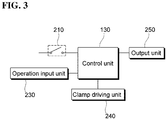
- FIG. 2 is an exemplary circuit diagram for safe clamp operation according to an embodiment.
- An apparatus for controlling quick clamping may include a selection input unit 10, a controller 20, a clamp driving unit 30, and operation input units 40 and 50.
- the clamp driving unit 30 may include a clamp valve that is connected to a clamp driving unit, e.g., a hydraulic cylinder, to control the supply of a working fluid to the clamp driving unit.
- a clamp driving unit e.g., a hydraulic cylinder
- the controller 20 may control the operation of the clamp by controlling the clamp driving unit 30.
- the selection input unit 10 is an input device for an operator to select a clamp operation. When the operator operates the selection input unit 10 to select the clamp operation, the selection input unit 10 generates a selection signal and transmits it to the controller 20.
- the operation input units 40 and 50 are provided in a driver's cabin, and when operated by the operator, they generate an operation signal to be transmitted to the controller 20.
- the controller 20 may control the clamp driving unit 30 so that a clamp may be operated to maintain a release state while the operation signal is input.
- the clamp driving unit 30 is provided in the form of a solenoid valve.
- the selection input unit 10 is provided in the form of a toggle switch that may be switched on and off by one-touch operation of the operator, and when an on state is selected, the selection input unit 10 may maintain a state where a clamp release driving is selected.
- the operation input units 40 and 50 are provided as an operational device in the form of at least two buttons, and may transmit the operation signal to the controller 20 while the operation input units 40 and 50 are operated by the operator.
- the operation input units 40 and 50 may generate the operation signal by a pressing operation, and may transmit the operation signal to the controller 20 while the operator presses the operation input unit 40 and 50. Accordingly, when the operator stops operation of any one of the operation input units 40 and 50, the controller 20 may control the clamp driving unit 30 to switch the clamp from the released state to a fastened state.
- the selection input unit 10 and the operation input units 40 and 50 may be provided in the form of an electrostatic input device provided separately on an instrument panel screen or a control box.
- the controller 20 according to the present embodiment is provided in the form of a machine control device for controlling the operation of the construction machine, the controller 20 may be configured to perform its function at a separate control device provided in an electrical equipment such as an instrument panel.
- the apparatus for controlling quick clamping connects the controller 20 to the selection input unit 10, the clamp driving unit 30, and the operation input units 40 and 50 through a first signal line L1, a second signal line L2, a third signal line L3, a fourth signal line L4.
- the first signal line L1 connects the selection input unit 10 and the controller 20.
- the second signal line L2 connects the clamp driving unit 30 and the controller 20.
- the third signal line L3 and the fourth signal line L4 connect the operation input units 40 and 50 and the controller 20, respectively.
- the first signal line L1 and the second signal line L2 are connected to each other through the clamp valve 30.
- the clamp driving unit 30 When a clamp release driving signal is output from the controller 20 to the second signal line L2 after the operator operates the selection input unit 10 and a clamp release mode is selected, the clamp driving unit 30 is operated to perform a clamp release operation.
- the above-described clamp release driving signal may be output from the controller 20 only when the operation input units 40 and 50 are further operated and the operation signal is input to the third signal line L3 and the fourth signal line L4. That is, the clamp valve 30 may not be operated only by the operation of the selection input unit 10 by the operator. This is to prevent the clamp from being released even though the selection input unit 10 is operated by the operator by mistake.
- the controller 20 may be connected to an output unit (not illustrated) through a separate signal line (not illustrated) and may output at least one of a warning sound and a warning display through the output unit when the selection input unit 10 is switched on. This may help the operator to recognize that the clamp release driving is currently selected.
- the operation input units 40 and 50 in the present embodiment may be installed at a joystick provided in a driver's cabin of the construction machine.
- the joystick is for operating a working device of the construction machine, e.g., a boom, an arm, and a bucket.
- a working device of the construction machine e.g., a boom, an arm, and a bucket.
- two joysticks are respectively installed on the left and right sides of the driver's cabin.
- Such a joystick includes a plurality of operation buttons or switches so that additional functions may be performed in addition to the driving operation of the working device. When each of the operation buttons or switches is operated, it may individually operate a predetermined specific function.
- the left joystick may include a plurality of operation buttons or switches including an engine deceleration selection operation button for forcing engine deceleration and a rotation operation switch for adjusting rotation of a rotatable optional working device.
- the right joystick may include a plurality of operation buttons or switches including a rotary switch for operating two-way optional working device and a pressure-up operation button for temporarily increasing a relief pressure of a hydraulic system of the construction machine.
- the operation input units 40 and 50 may be configured as one of the operation buttons of the left joystick and one of the operation buttons of the right joystick.
- FIG. 2 shows an embodiment in which the operation input units 40 and 50 are in the form of an operation button type, i.e., the engine deceleration selection operation button and the pressure-up operation button.
- the corresponding operation buttons are involved in the clamp release driving, instead of specific functions thereof. That is, a specific function mode in which the specific function is performed when the operation buttons are operated is cancelled.
- the controller 20 recognizes the operation signal as a driving signal for driving the clamp when the selection input unit 10 is switched on; and recognizes it as a driving signal for performing the specific function of each operation button when the selection input unit 10 is switched off.
- an engine deceleration selection signal is output when the engine deceleration selection operation button is operated by the operator, and a pressure-up selection signal is output when the pressure-up operation button is operated by the operator.
- the operation input units 40 and 50 are provided as the operation buttons at the left and right joysticks, the operator may proceed with the clamp release operation only when both hands are simultaneously used. Accordingly, it is possible to suppress the occurrence of a safety accident because the possibility of the operator erroneously using both hands at the same time is low.
- the operation input units 40 and 50 may be configured to generate a driving signal while the operator is performing a pressing operation. That is, the operation input units 40 and 50 should be held in a pressing operation state while the clamp release driving proceeds. This also improves the effects of preventing the safety accident caused by the operator's mistake.
- both of the operation input units 40 and 50 respectively disposed at the left and right joysticks may be easily operated by two hands.
- FIG. 3 is a schematic block diagram illustrating an apparatus for controlling quick clamping of construction machine according to an embodiment.
- an apparatus for controlling quick clamping may include a selection input unit 210, a controller 220, an operation input unit 230, a clamp driving unit 240, and an output unit 250.
- the selection input unit 210 When switched on, the selection input unit 210 generates a signal for releasing the clamp.
- the signal generated when the selection input unit 210 is switched on or off is transmitted to the controller 220.
- the controller 220 controls each component so that an operation safety device may secure the safety of the operation.
- an on signal is input from the selection input unit 210 and a signal from the operation input unit 230 is generated, the controller 220 controls so that clamping of the attachment is released.
- the operation input unit 230 generates a predetermined signal by operator's operation. The generated signal is transmitted to the controller 220.
- the operation input unit 230 may include one or more of any buttons or switches provided at the construction machine, such as a button on the left joystick, a button on the right joystick, or any button on the instrument panel.
- the output unit 250 may visually display an alarm or notify the alarm audibly in accordance with an instruction from the controller 220.
- the output unit 250 may include at least one of a display device, e.g., an instrument panel, and a speaker.
- a display device e.g., an instrument panel
- a speaker e.g., a speaker
- the controller 220 When the controller 220 receives the signal generated by turning on the selection input unit 210, the controller 220 deactivates the specific function mode matched with the signal generated by the operation input unit 230, and determines it as an additional input signal for releasing the clamp.
- the specific function mode is a mode for performing a specific function which is set according to the signal of the operation input unit 230.
- the specific functions are the same as those described above, and a detailed description thereof will be omitted.
- the controller 220 when the controller 220 receives the signal generated by turning on the selection input unit 210, the controller 220 outputs an alarm to notify the operator that the selection input unit 210 is switched on.
- the controller 220 recognizes the signal generated by the operation input unit 230 as an operation signal for the operator to release the clamp.
- the controller 220 when the controller 220 receives the signal generated by the operation input unit 230 in a state where the selection input unit 210 is switched on, the controller 220 controls the clamp to be released.
- FIG. 4 is a view illustrating a method for controlling quick clamping of construction machine according to an embodiment
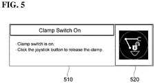
- FIG. 5 is a view illustrating an example of an alarm display displayed on an output unit according to an embodiment.
- the selection input unit is switched on (S110), and a signal generated by a switch-on switching is transmitted to the controller.
- the controller deactivates the specific function mode of the input unit (S120).
- the controller informs the operator that the selection input unit has been switched on, so that the operator may recognize it (S130).
- the above-mentioned notification may be made through a warning sound.
- the controller may control a sound device in the driver's cab, for example, a speaker, a pilot buzzer, etc. so that a beep sound may be output in the driver's cab. This warning sound may continue until the selection input unit is switched off.
- a text 510 indicating that the selection input unit is switched on and a symbol 502 indicating that the selection input unit is switched on may be displayed on the display device such as the instrument panel of the construction machine.
- the display text may be output on the display device in a pop-up format.
- This display text may be set to disappear automatically when the selection input unit is switched off again or when the operation input unit (the left joystick button and the right joystick button in the present embodiment) is operated and the clamp is released.
- step S140 the controller determines that the operator desires to release clamping and instructs the release of clamping of the attachment (S150).
- step S140 the controller determines that the operator does not want the release of clamping and confirms whether the clamp is switched off (S160).
- step S160 If the selection input unit is not switched off in step S160, the process returns to step S120 to notify that the selection input unit is in the on state.
- monitoring whether a pilot cutoff signal is input may be added prior to step S I 10.
- step S 110 If the pilot cutoff signal is not input, operation of the machine is stopped, and the process may then proceed to a clamp safe operation step (after step S 110) only when the pilot cutoff signal is not input.
- the apparatus for controlling quick clamping may substantially prevent a safety accident that may occur when an operator operates the control apparatus unintentionally and the attachment is released.
- the invention disclosed herein is industrially applicable since it can promote sales of the construction machine applied with the relevant technology and it is clearly described to be practically possible to carry out, by including a structure for generating a warning sound unless both hands of the operator are in continuous operation during the operation of a quick coupler, thus improving convenience and safety at the same time.
Landscapes
- Engineering & Computer Science (AREA)
- General Engineering & Computer Science (AREA)
- Mining & Mineral Resources (AREA)
- Civil Engineering (AREA)
- Structural Engineering (AREA)
- Mechanical Engineering (AREA)
- Physics & Mathematics (AREA)
- General Physics & Mathematics (AREA)
- Electromagnetism (AREA)
- Fluid Mechanics (AREA)
- Operation Control Of Excavators (AREA)
- Component Parts Of Construction Machinery (AREA)
- Mechanical Control Devices (AREA)
Abstract
Description
- Embodiments of the present invention relate to an apparatus for controlling and a method for controlling quick clamping of construction machine.
- In general, heavy machiney, e.g., excavators, used in construction site or civil engineering works are provided with various replaceable attachments for multiple uses, for example, digging the ground using a bucket, dismantling concrete buildings and cutting rebar using a crusher, breaking rock and concrete using a breaker, transporting scrap iron and rock using a grab, foundation works for a vertical shaft, water supply, and sewage system using a clamshell bucket.
- The attachment is detachably coupled to an arm or a boom of the excavator to be replaceable according to the usage of the operation.
- For conventional heavy machine, in order to facilitate the replacement of such attachments, quick clamping function for releasing a clamp of the attachment only by a switch input is applied
FIG. 1 is an exemplary circuit diagram for performing a quick clamping function of conventional heavy machine. - As illustrated in
FIG. 1 , amachine control apparatus 2 activates aclamp solenoid valve 3 to perform a function of releasing an attachment, when a toggle switch 1 is switched on. - Such a quick clamping function allows easy replacement of attachments. However, there is a problem that an operator may operate the control apparatus unintentionally, leading to an accident that the attachment is released.
- It is to be understood that this background of the technology section is intended to provide useful background for understanding the technology and as such disclosed herein, the technology background section may include ideas, concepts or recognitions that were not part of what was known or appreciated by those skilled in the pertinent art prior to a corresponding effective filing date of subject matter disclosed herein.
- Embodiments of the present invention may be directed to an apparatus for controlling quick clamping of construction machine that may substantially prevent an accident that may occur when an operator operates the control apparatus unintentionally and the attachment is released.
- In addition, embodiments of the present invention may further be directed to an apparatus for controlling quick clamping of construction machine that is realized by using a switch or an input button which is a conventionally provided element, instead of additionally providing a separate switch.
- According to an embodiment, an apparatus for controlling quick clamping of construction machine which comprises a clamp for mounting an attachment includes: a selection input unit for generating a selection signal during an on operation by an operator; an operation input unit for generating an operation signal during an operation by the operator; a clamp driving unit for releasing and fastening the clamp; and a controllercontroller for controlling the clamp driving unit to release the clamp while the operation signal is input after the selection signal is input.
- The operation input unit may generate the operation signal while the operator holds a pressing operation, and the controllercontroller may control the clamp driving unit so that the clamp is in a released state while input of the operation signal continues.
- The operation input unit may include a plurality of operation input units so that the operator operates the operation input unit using both hands simultaneously.
- The operation input unit may include one of a plurality of operation buttons and switches provided at a left joystick, and one of a plurality of operation buttons and switches provided at a right joystick.
- When the pressing operation on one of the plurality of operation input units is stopped, the controllercontroller may control the clamp driving unit to fasten the clamp.
- The apparatus may further include an output unit for outputting at least one of an alarm message and a warning sound. When the controller receives the selection signal, the controller may control the output unit to output at least one of the alarm message and the alarm sound.
- When the selection input unit is switched off and generation of the selection signal is stopped, the controller may control the output unit to stop outputting the warning sound.
- When the selection input unit is switched off and generation of the selection signal is stopped, the controller may activate a specific function mode controlled by the signal generated from the operation input unit. When the selection input unit is switched on and the selection signal is input, the controller may deactivate the specific function mode controlled by the signal generated from the operation input unit.
- The operation input unit may include one of a plurality of operation buttons and switches provided at a left joystick and one of a plurality of operation buttons and switches provided at a right joystick, and require simultaneous operation of both hands of the operator.
- The specific function of the selected operation button of the left joystick may be an engine deceleration selection signal output, and the specific function of the selected operation button of the right joystick may be a pressure-up selection signal output.
- The controller may monitor input of a pilot cutoff signal, and controls the clamp driving unit so that the clamp is released only when the pilot cutoff signal is not input.
- According to an embodiment, a method of controlling quick clamping of construction machine which comprises a clamp for mounting an attachment includes: a selection signal being input to a controller, the selection signal generated when an operator switches on a selection input unit; an operation signal being input to the controller, the operation signal generated when the operator presses an operation input unit; and a controller controlling the clamp to be released while the operation signal is input after the selection signal is input.
- According to one or more embodiments of the present invention, an apparatus for controlling quick clamping of construction machine may substantially prevent an accident that may occur when a clamp release function is activated without the intention of the driver and the attachment is detached.
-
-
FIG. 1 is an exemplary circuit diagram for performing a quick clamping function of conventional heavy machine. -
FIG. 2 is an exemplary circuit diagram for safe clamp operation according to an embodiment. -
FIG. 3 is a schematic block diagram illustrating an apparatus for controlling quick clamping of construction machine according to an embodiment. -
FIG. 4 is a view illustrating a method for controlling quick clamping of construction machine according to an embodiment. -
FIG. 5 is a view illustrating an example of an alarm display displayed on an output unit according to an embodiment. - Embodiments will now be described more fully hereinafter with reference to the accompanying drawings. Although the invention may be modified in various manners and have several embodiments, embodiments are illustrated in the accompanying drawings and will be mainly described in the specification. However, the scope of the present invention is not limited to the embodiments and should be construed as including all the changes, equivalents and substitutions included in the spirit and scope of the present invention. It is noted that the technical terms used herein are used only to describe specific embodiments and are not intended to limit the invention. It is also to be understood that the technical terms used herein are to be interpreted in a sense generally understood by a person skilled in the art to which the present invention belongs, and should not be construed to mean, or be interpreted in an excessively reduced sense. Further, when a technical term used herein is an erroneous technical term that does not accurately express the spirit of the present invention, it can be replaced with the technical terms that can be understood by a person skilled in the art. In addition, the general terms used in the present invention should be interpreted according to a predefined or prior context, and should not be construed as being excessively reduced.
- Throughout the specification, the singular forms "a", "an" and "the" include plural referents unless the context clearly dictates otherwise. It will be understood that the terms "comprises," "comprising," "includes" and/or "including," when used in this specification, specify the presence of stated features, integers, steps, operations, elements, and/or components, but do not preclude the presence or addition of one or more other features, integers, steps, operations, elements, components, and/or groups thereof.
- Further, the suffixes "module," "part," "portion," and "unit" for components used in the present specification are given or mixed in consideration of ease of specification, and do not have their own meaning or role.
- It will be understood that, although the terms "first," "second," "third," and the like may be used herein to describe various elements, these elements should not be limited by these terms. These terms are only used to distinguish one element from another element. Thus, "a first element" discussed below could be termed "a second element" or "a third element," and "a second element" and "a third element" may be termed likewise without departing from the teachings herein.
- Hereinafter, exemplary embodiments of the present invention will be described in detail with reference to the accompanying drawings, where like reference numerals refer to like or similar elements throughout the several views, and redundant description thereof will be omitted.
- In the following description, well-known functions or configurations are not described in detail since they would obscure the invention in unnecessary detail.
- It is to be noted that the accompanying drawings are only for the purpose of facilitating understanding of the present invention, and should not be construed as limiting the scope of the present invention with reference to the accompanying drawings.
-
FIG. 2 is an exemplary circuit diagram for safe clamp operation according to an embodiment. - An apparatus for controlling quick clamping according to an embodiment may include a
selection input unit 10, acontroller 20, aclamp driving unit 30, andoperation input units 40 and 50. - The
clamp driving unit 30 may include a clamp valve that is connected to a clamp driving unit, e.g., a hydraulic cylinder, to control the supply of a working fluid to the clamp driving unit. - The
controller 20 may control the operation of the clamp by controlling theclamp driving unit 30. - The
selection input unit 10 is an input device for an operator to select a clamp operation. When the operator operates theselection input unit 10 to select the clamp operation, theselection input unit 10 generates a selection signal and transmits it to thecontroller 20. - The
operation input units 40 and 50, separately from theselection input unit 10, are provided in a driver's cabin, and when operated by the operator, they generate an operation signal to be transmitted to thecontroller 20. As described above, when the operation signal is input after the selection signal generated by operation of the operator is input, thecontroller 20 may control theclamp driving unit 30 so that a clamp may be operated to maintain a release state while the operation signal is input. - In an embodiment illustrated in
FIG. 2 , theclamp driving unit 30 is provided in the form of a solenoid valve. Theselection input unit 10 is provided in the form of a toggle switch that may be switched on and off by one-touch operation of the operator, and when an on state is selected, theselection input unit 10 may maintain a state where a clamp release driving is selected. Theoperation input units 40 and 50 are provided as an operational device in the form of at least two buttons, and may transmit the operation signal to thecontroller 20 while theoperation input units 40 and 50 are operated by the operator. Theoperation input units 40 and 50 according to the present embodiment may generate the operation signal by a pressing operation, and may transmit the operation signal to thecontroller 20 while the operator presses theoperation input unit 40 and 50. Accordingly, when the operator stops operation of any one of theoperation input units 40 and 50, thecontroller 20 may control theclamp driving unit 30 to switch the clamp from the released state to a fastened state. - The
selection input unit 10 and theoperation input units 40 and 50 may be provided in the form of an electrostatic input device provided separately on an instrument panel screen or a control box. Although thecontroller 20 according to the present embodiment is provided in the form of a machine control device for controlling the operation of the construction machine, thecontroller 20 may be configured to perform its function at a separate control device provided in an electrical equipment such as an instrument panel. - The apparatus for controlling quick clamping according to an embodiment connects the
controller 20 to theselection input unit 10, theclamp driving unit 30, and theoperation input units 40 and 50 through a first signal line L1, a second signal line L2, a third signal line L3, a fourth signal line L4. The first signal line L1 connects theselection input unit 10 and thecontroller 20. The second signal line L2 connects theclamp driving unit 30 and thecontroller 20. The third signal line L3 and the fourth signal line L4 connect theoperation input units 40 and 50 and thecontroller 20, respectively. The first signal line L1 and the second signal line L2 are connected to each other through theclamp valve 30. When a clamp release driving signal is output from thecontroller 20 to the second signal line L2 after the operator operates theselection input unit 10 and a clamp release mode is selected, theclamp driving unit 30 is operated to perform a clamp release operation. The above-described clamp release driving signal may be output from thecontroller 20 only when theoperation input units 40 and 50 are further operated and the operation signal is input to the third signal line L3 and the fourth signal line L4. That is, theclamp valve 30 may not be operated only by the operation of theselection input unit 10 by the operator. This is to prevent the clamp from being released even though theselection input unit 10 is operated by the operator by mistake. In an embodiment, thecontroller 20 may be connected to an output unit (not illustrated) through a separate signal line (not illustrated) and may output at least one of a warning sound and a warning display through the output unit when theselection input unit 10 is switched on. This may help the operator to recognize that the clamp release driving is currently selected. - The
operation input units 40 and 50 in the present embodiment may be installed at a joystick provided in a driver's cabin of the construction machine. The joystick is for operating a working device of the construction machine, e.g., a boom, an arm, and a bucket. In the case of an excavator, for example, two joysticks are respectively installed on the left and right sides of the driver's cabin. Such a joystick includes a plurality of operation buttons or switches so that additional functions may be performed in addition to the driving operation of the working device. When each of the operation buttons or switches is operated, it may individually operate a predetermined specific function. For example, the left joystick may include a plurality of operation buttons or switches including an engine deceleration selection operation button for forcing engine deceleration and a rotation operation switch for adjusting rotation of a rotatable optional working device. In addition, the right joystick may include a plurality of operation buttons or switches including a rotary switch for operating two-way optional working device and a pressure-up operation button for temporarily increasing a relief pressure of a hydraulic system of the construction machine. In the present embodiment, theoperation input units 40 and 50 may be configured as one of the operation buttons of the left joystick and one of the operation buttons of the right joystick. -
FIG. 2 shows an embodiment in which theoperation input units 40 and 50 are in the form of an operation button type, i.e., the engine deceleration selection operation button and the pressure-up operation button. When a clamp release mode is selected by the operation of the operator through theselection input unit 10, the corresponding operation buttons are involved in the clamp release driving, instead of specific functions thereof. That is, a specific function mode in which the specific function is performed when the operation buttons are operated is cancelled. To this end, when the operation signal is applied by operating the operation buttons, thecontroller 20 recognizes the operation signal as a driving signal for driving the clamp when theselection input unit 10 is switched on; and recognizes it as a driving signal for performing the specific function of each operation button when theselection input unit 10 is switched off. In a specific function mode, in a case where the engine deceleration selection operation button and the pressure-up operation button are used as the operation input unit as in the present embodiment, an engine deceleration selection signal is output when the engine deceleration selection operation button is operated by the operator, and a pressure-up selection signal is output when the pressure-up operation button is operated by the operator. - As described above, since the
operation input units 40 and 50 are provided as the operation buttons at the left and right joysticks, the operator may proceed with the clamp release operation only when both hands are simultaneously used. Accordingly, it is possible to suppress the occurrence of a safety accident because the possibility of the operator erroneously using both hands at the same time is low. In addition, theoperation input units 40 and 50 may be configured to generate a driving signal while the operator is performing a pressing operation. That is, theoperation input units 40 and 50 should be held in a pressing operation state while the clamp release driving proceeds. This also improves the effects of preventing the safety accident caused by the operator's mistake. On the other hand, when the operator desires a clamp release operation, both of theoperation input units 40 and 50 respectively disposed at the left and right joysticks may be easily operated by two hands. -
FIG. 3 is a schematic block diagram illustrating an apparatus for controlling quick clamping of construction machine according to an embodiment. - As illustrated in
FIG. 3 , an apparatus for controlling quick clamping according to an embodiment may include aselection input unit 210, a controller 220, anoperation input unit 230, aclamp driving unit 240, and anoutput unit 250. - When switched on, the
selection input unit 210 generates a signal for releasing the clamp. - The signal generated when the
selection input unit 210 is switched on or off is transmitted to the controller 220. - The controller 220 controls each component so that an operation safety device may secure the safety of the operation. When an on signal is input from the
selection input unit 210 and a signal from theoperation input unit 230 is generated, the controller 220 controls so that clamping of the attachment is released. - The
operation input unit 230 generates a predetermined signal by operator's operation. The generated signal is transmitted to the controller 220. - The
operation input unit 230 may include one or more of any buttons or switches provided at the construction machine, such as a button on the left joystick, a button on the right joystick, or any button on the instrument panel. - The
output unit 250 may visually display an alarm or notify the alarm audibly in accordance with an instruction from the controller 220. - The
output unit 250 may include at least one of a display device, e.g., an instrument panel, and a speaker. - When the controller 220 receives the signal generated by turning on the
selection input unit 210, the controller 220 deactivates the specific function mode matched with the signal generated by theoperation input unit 230, and determines it as an additional input signal for releasing the clamp. As used herein, the specific function mode is a mode for performing a specific function which is set according to the signal of theoperation input unit 230. As used herein, the specific functions are the same as those described above, and a detailed description thereof will be omitted. - At the same time, when the controller 220 receives the signal generated by turning on the
selection input unit 210, the controller 220 outputs an alarm to notify the operator that theselection input unit 210 is switched on. - In a state in which the
selection input unit 210 is switched on, that is, in a state in which the specific function mode of theoperation input unit 230 is deactivated, the controller 220 recognizes the signal generated by theoperation input unit 230 as an operation signal for the operator to release the clamp. - Accordingly, when the controller 220 receives the signal generated by the
operation input unit 230 in a state where theselection input unit 210 is switched on, the controller 220 controls the clamp to be released. -
FIG. 4 is a view illustrating a method for controlling quick clamping of construction machine according to an embodiment, andFIG. 5 is a view illustrating an example of an alarm display displayed on an output unit according to an embodiment. - Prior to the description, it is assumed that both of the left button and the right button of the joystick are used as an input unit in the present embodiment.
- Referring to
FIG. 4 , first, the selection input unit is switched on (S110), and a signal generated by a switch-on switching is transmitted to the controller. - The controller deactivates the specific function mode of the input unit (S120).
- At the same time, the controller informs the operator that the selection input unit has been switched on, so that the operator may recognize it (S130).
- The above-mentioned notification may be made through a warning sound. When the selection input unit is switched on, the controller may control a sound device in the driver's cab, for example, a speaker, a pilot buzzer, etc. so that a beep sound may be output in the driver's cab. This warning sound may continue until the selection input unit is switched off.
- In addition, as illustrated in
FIG. 5 , atext 510 indicating that the selection input unit is switched on and a symbol 502 indicating that the selection input unit is switched on may be displayed on the display device such as the instrument panel of the construction machine. The display text may be output on the display device in a pop-up format. - This display text may be set to disappear automatically when the selection input unit is switched off again or when the operation input unit (the left joystick button and the right joystick button in the present embodiment) is operated and the clamp is released.
- Referring again to
FIG. 4 , it is monitored whether a signal is generated from the left joystick button and the right joystick button (S140). - If the signal generated from the left joystick button and the right joystick button is input to the controller in step S140, the controller determines that the operator desires to release clamping and instructs the release of clamping of the attachment (S150).
- If no signal is generated from either the left joystick button or the right joystick button in step S140, the controller determines that the operator does not want the release of clamping and confirms whether the clamp is switched off (S160).
- If the selection input unit is not switched off in step S160, the process returns to step S120 to notify that the selection input unit is in the on state.
- In another modified embodiment, monitoring whether a pilot cutoff signal is input may be added prior to step
S I 10. - If the pilot cutoff signal is not input, operation of the machine is stopped, and the process may then proceed to a clamp safe operation step (after step S 110) only when the pilot cutoff signal is not input.
- In other words, since the working device is in operation if the pilot cutoff signal is input, the clamp release function is not performed even though the clamp is switched on.
- The apparatus for controlling quick clamping according to an embodiment may substantially prevent a safety accident that may occur when an operator operates the control apparatus unintentionally and the attachment is released.
- It will be understood by those skilled in the art that the foregoing description of the present invention is for illustrative purposes only and that those of ordinary skill in the art may readily understand that various changes and modifications may be made without departing from the spirit or essential characteristics of the present invention. It is therefore to be understood that the above-described embodiments are illustrative in all aspects and not restrictive. For example, each component described as a single entity may be distributed and implemented, and components described as being distributed may also be implemented in a combined form.
- While the present invention has been particularly shown and described with reference to exemplary embodiments thereof, although specific terms have been employed, they have been used in a generic sense only to facilitate the description of the subject matter of the specification and to aid the understanding of the invention, and it is not intended to limit the scope of the specification. It will be apparent to those skilled in the art that other modifications based on the technical idea of the present invention are possible in addition to the embodiments disclosed herein.
- The invention disclosed herein is industrially applicable since it can promote sales of the construction machine applied with the relevant technology and it is clearly described to be practically possible to carry out, by including a structure for generating a warning sound unless both hands of the operator are in continuous operation during the operation of a quick coupler, thus improving convenience and safety at the same time.
Claims (15)
- An apparatus for controlling quick clamping of construction machine which comprises a clamp for mounting an attachment, the apparatus comprising:a selection input unit for generating a selection signal during an on operation by an operator;an operation input unit for generating an operation signal during an operation by the operator;a clamp driving unit for releasing and fastening the clamp; anda controller for controlling the clamp driving unit to release the clamp while the operation signal is input after the selection signal is input.
- The apparatus of claim 1, wherein the operation input unit generates the operation signal while the operator holds a pressing operation, and
the controller controls the clamp driving unit so that the clamp is in a released state while input of the operation signal continues. - The apparatus of claim 2, wherein the operation input unit comprises a plurality of operation input units so that the operator operates the operation input unit using both hands simultaneously.
- The apparatus of claim 3, wherein the operation input unit comprises one of a plurality of operation buttons and switches provided at a left joystick, and one of a plurality of operation buttons and switches provided at a right joystick.
- The apparatus of claim 4, wherein when the pressing operation on one of the plurality of operation input units is stopped, the controller controls the clamp driving unit to fasten the clamp.
- The apparatus of claim 1, further comprising an output unit for outputting at least one of an alarm message and a warning sound,
wherein when the controller receives the selection signal, the controller controls the output unit to output at least one of the alarm message and the alarm sound. - The apparatus of claim 6, wherein when the selection input unit is switched off and generation of the selection signal is stopped, the controller controls the output unit to stop outputting the warning sound.
- The apparatus of claim 1, wherein when the selection input unit is switched off and generation of the selection signal is stopped, the controller activates a specific function mode controlled by the signal generated from the operation input unit; and
when the selection input unit is switched on and the selection signal is input, the controller deactivates the specific function mode controlled by the signal generated from the operation input unit. - The apparatus of claim 8, wherein the operation input unit comprises one of a plurality of operation buttons and switches provided at a left joystick and one of a plurality of operation buttons and switches provided at a right joystick, and requires simultaneous operation of both hands of the operator.
- The apparatus of claim 9, wherein the specific function of the selected operation button of the left joystick is an engine deceleration selection signal output, and the specific function of the selected operation button of the right joystick is a pressure-up selection signal output.
- The apparatus of claim 1, wherein the controller monitors input of a pilot cutoff signal, and controls the clamp driving unit so that the clamp is released only when the pilot cutoff signal is not input.
- A method of controlling quick clamping of construction machine which comprises a clamp for mounting an attachment, the method comprising:a selection signal being input to a controller, the selection signal generated when an operator switches on a selection input unit;an operation signal being input to the controller, the operation signal generated when the operator presses an operation input unit; anda controller controlling the clamp to be released while the operation signal is input after the selection signal is input.
- The apparatus of claim 12, wherein the operation input unit comprises one of a plurality of operation buttons and switches provided at a left joystick and one of a plurality of operation buttons and switches provided at a right joystick, and requires simultaneous operation of both hands of the operator.
- The method of claim 12, wherein the controller deactivates a specific function mode, controlled by the operation signal output from the operation input unit, after the selection signal is input, and
the controller activates the specific function mode of the operation input unit when generation of the selection signal is stopped by switching off the selection input unit. - The method of claim 12, wherein the controller controls an output unit to output at least one of an alarm message and an alarm sound after the selection signal is input, and
outputting of at least one of the alarm message and the alarm sound is stopped when the operator switches off the selection input unit.
Applications Claiming Priority (2)
| Application Number | Priority Date | Filing Date | Title |
|---|---|---|---|
| KR20170008285 | 2017-01-17 | ||
| PCT/KR2018/000798 WO2018135854A1 (en) | 2017-01-17 | 2018-01-17 | Apparatus for controlling and method for controlling quick-clamp of construction machine |
Publications (3)
| Publication Number | Publication Date |
|---|---|
| EP3569776A1 true EP3569776A1 (en) | 2019-11-20 |
| EP3569776A4 EP3569776A4 (en) | 2020-03-25 |
| EP3569776B1 EP3569776B1 (en) | 2024-05-01 |
Family
ID=62909299
Family Applications (1)
| Application Number | Title | Priority Date | Filing Date |
|---|---|---|---|
| EP18741897.5A Active EP3569776B1 (en) | 2017-01-17 | 2018-01-17 | Apparatus for controlling and method for controlling quick-clamp of construction machine |
Country Status (6)
| Country | Link |
|---|---|
| US (1) | US11692329B2 (en) |
| EP (1) | EP3569776B1 (en) |
| JP (1) | JP6915065B2 (en) |
| KR (1) | KR102189423B1 (en) |
| CN (1) | CN110191991B (en) |
| WO (1) | WO2018135854A1 (en) |
Families Citing this family (3)
| Publication number | Priority date | Publication date | Assignee | Title |
|---|---|---|---|---|
| KR102814077B1 (en) * | 2020-03-09 | 2025-05-28 | 에이치디현대인프라코어 주식회사 | Method of controlling a quick coupler of a construction machine and apparatus for performing the same |
| KR102700270B1 (en) * | 2021-04-05 | 2024-08-29 | 에이치디현대건설기계 주식회사 | Horn control device of a construction equipment |
| CN115450210B (en) * | 2022-08-23 | 2024-09-03 | 中联重科土方机械有限公司 | Control method, controller and clamping device for clamping device of engineering machinery |
Family Cites Families (14)
| Publication number | Priority date | Publication date | Assignee | Title |
|---|---|---|---|---|
| ATE342406T1 (en) * | 2001-12-06 | 2006-11-15 | Geith Patents Ltd | QUICK TOOL COUPLING FOR COUPLING AN ATTACHMENT TO AN EXCAVATOR ARM AND THE QUICK TOOL COUPLING COMPRISES A CONTROL SYSTEM |
| KR200319139Y1 (en) * | 2003-02-06 | 2003-07-07 | 주식회사수산중공업 | safety-equipment for quick-clamp |
| US7455494B2 (en) * | 2005-12-02 | 2008-11-25 | Clark Equipment Company | Control circuit for an attachment mounting device |
| US7467918B2 (en) * | 2006-10-26 | 2008-12-23 | Deere & Company | Remote controlled latching system |
| JP2008266975A (en) | 2007-04-19 | 2008-11-06 | Caterpillar Japan Ltd | Control unit of working machine |
| US8469623B2 (en) * | 2009-04-01 | 2013-06-25 | Caterpillar Work Tools B.V. | Quick coupling device |
| GB2474572B (en) * | 2009-10-16 | 2014-11-26 | Hill Engineering Ltd | Control system for a hydraulic coupler |
| GB201108376D0 (en) | 2011-05-19 | 2011-06-29 | Shadowfiction Ltd | An automatic quick hitch for an extractor |
| EP2798126B1 (en) * | 2011-12-29 | 2019-08-07 | Clark Equipment Company | Electronic tag along |
| DE202012009838U1 (en) | 2012-07-24 | 2013-10-25 | Kinshofer Gmbh | Quick coupler |
| JP6176666B2 (en) * | 2014-04-08 | 2017-08-09 | キャタピラー エス エー アール エル | Control device for quick coupler in work machine |
| KR102241176B1 (en) | 2014-04-10 | 2021-04-16 | 두산인프라코어 주식회사 | Method of controlling a quick coupler of an excavator and apparatus for performing the same |
| US9970177B2 (en) * | 2015-05-04 | 2018-05-15 | Deere & Company | Quick coupler having spring applied, hydraulically released primary and secondary lock members mounted on same cross shaft |
| KR101734763B1 (en) * | 2016-04-25 | 2017-05-11 | 임용태 | Safety quick coupler having advanced structure for excavator |
-
2018
- 2018-01-17 CN CN201880007366.8A patent/CN110191991B/en active Active
- 2018-01-17 KR KR1020197020485A patent/KR102189423B1/en active Active
- 2018-01-17 US US16/478,308 patent/US11692329B2/en active Active
- 2018-01-17 WO PCT/KR2018/000798 patent/WO2018135854A1/en not_active Ceased
- 2018-01-17 EP EP18741897.5A patent/EP3569776B1/en active Active
- 2018-01-17 JP JP2019538496A patent/JP6915065B2/en active Active
Also Published As
| Publication number | Publication date |
|---|---|
| CN110191991B (en) | 2021-09-21 |
| EP3569776B1 (en) | 2024-05-01 |
| KR20190090021A (en) | 2019-07-31 |
| WO2018135854A1 (en) | 2018-07-26 |
| JP2020506313A (en) | 2020-02-27 |
| US11692329B2 (en) | 2023-07-04 |
| KR102189423B1 (en) | 2020-12-11 |
| EP3569776A4 (en) | 2020-03-25 |
| CN110191991A (en) | 2019-08-30 |
| JP6915065B2 (en) | 2021-08-04 |
| US20190390437A1 (en) | 2019-12-26 |
Similar Documents
| Publication | Publication Date | Title |
|---|---|---|
| US11692329B2 (en) | Apparatus for controlling and method for controlling quick-clamping of construction machine | |
| EP4012121A1 (en) | Work machine and surrounding monitoring system | |
| KR101433801B1 (en) | Industrial vehicle and control method for industrial vehicle | |
| US8862274B2 (en) | Electro-hydraulic auxiliary control with operator-selectable flow setpoint | |
| EP4050165A1 (en) | Remote control system for construction machine | |
| KR102841525B1 (en) | construction machinery | |
| KR102241176B1 (en) | Method of controlling a quick coupler of an excavator and apparatus for performing the same | |
| KR102816375B1 (en) | Construction machinery | |
| KR101616638B1 (en) | Circuit for controlling crab of overhead crane | |
| CN211774104U (en) | Auxiliary visual field system and loader-digger | |
| JP2018159182A (en) | Stopping device | |
| KR101735107B1 (en) | Control system for a tilting cabin | |
| KR101263955B1 (en) | Apparatus for operating swing break | |
| JP2740442B2 (en) | Crane operating device | |
| CN214194734U (en) | Breaker controlling means and crushing equipment | |
| EP4424931A1 (en) | Construction machine | |
| KR102000411B1 (en) | Cranes and gantry cranes | |
| JP2013189828A (en) | Hydraulic pressure type work machine | |
| JP2005061014A (en) | Construction machine | |
| KR102162601B1 (en) | Safety control appartus and safety control method for attachment of construction machinery | |
| JP4627280B2 (en) | Hydraulic control device of excavator | |
| JP2005354479A (en) | Radio remote control system of operating machine | |
| JP6012079B2 (en) | Construction machine remote control system | |
| EP4596798A1 (en) | Work machine | |
| KR20140080765A (en) | Monitor control method using joystick |
Legal Events
| Date | Code | Title | Description |
|---|---|---|---|
| STAA | Information on the status of an ep patent application or granted ep patent |
Free format text: STATUS: THE INTERNATIONAL PUBLICATION HAS BEEN MADE |
|
| PUAI | Public reference made under article 153(3) epc to a published international application that has entered the european phase |
Free format text: ORIGINAL CODE: 0009012 |
|
| STAA | Information on the status of an ep patent application or granted ep patent |
Free format text: STATUS: REQUEST FOR EXAMINATION WAS MADE |
|
| 17P | Request for examination filed |
Effective date: 20190812 |
|
| AK | Designated contracting states |
Kind code of ref document: A1 Designated state(s): AL AT BE BG CH CY CZ DE DK EE ES FI FR GB GR HR HU IE IS IT LI LT LU LV MC MK MT NL NO PL PT RO RS SE SI SK SM TR |
|
| AX | Request for extension of the european patent |
Extension state: BA ME |
|
| RIN1 | Information on inventor provided before grant (corrected) |
Inventor name: PARK, JUN HONG Inventor name: LIM, YOUNG SUP Inventor name: PARK, DUCK WOO |
|
| A4 | Supplementary search report drawn up and despatched |
Effective date: 20200225 |
|
| RIC1 | Information provided on ipc code assigned before grant |
Ipc: E02F 9/20 20060101ALI20200219BHEP Ipc: E02F 9/24 20060101AFI20200219BHEP Ipc: E02F 9/26 20060101ALI20200219BHEP Ipc: E02F 3/36 20060101ALI20200219BHEP |
|
| DAV | Request for validation of the european patent (deleted) | ||
| DAX | Request for extension of the european patent (deleted) | ||
| RAP3 | Party data changed (applicant data changed or rights of an application transferred) |
Owner name: HYUNDAI DOOSAN INFRACORE CO., LTD. |
|
| STAA | Information on the status of an ep patent application or granted ep patent |
Free format text: STATUS: EXAMINATION IS IN PROGRESS |
|
| 17Q | First examination report despatched |
Effective date: 20230221 |
|
| GRAP | Despatch of communication of intention to grant a patent |
Free format text: ORIGINAL CODE: EPIDOSNIGR1 |
|
| STAA | Information on the status of an ep patent application or granted ep patent |
Free format text: STATUS: GRANT OF PATENT IS INTENDED |
|
| INTG | Intention to grant announced |
Effective date: 20231129 |
|
| RIN1 | Information on inventor provided before grant (corrected) |
Inventor name: PARK, DUCK WOO Inventor name: PARK, JUN HONG Inventor name: LIM, YOUNG SUP |
|
| RAP3 | Party data changed (applicant data changed or rights of an application transferred) |
Owner name: HD HYUNDAI INFRACORE CO., LTD. |
|
| GRAS | Grant fee paid |
Free format text: ORIGINAL CODE: EPIDOSNIGR3 |
|
| GRAA | (expected) grant |
Free format text: ORIGINAL CODE: 0009210 |
|
| STAA | Information on the status of an ep patent application or granted ep patent |
Free format text: STATUS: THE PATENT HAS BEEN GRANTED |
|
| AK | Designated contracting states |
Kind code of ref document: B1 Designated state(s): AL AT BE BG CH CY CZ DE DK EE ES FI FR GB GR HR HU IE IS IT LI LT LU LV MC MK MT NL NO PL PT RO RS SE SI SK SM TR |
|
| REG | Reference to a national code |
Ref country code: GB Ref legal event code: FG4D |
|
| REG | Reference to a national code |
Ref country code: CH Ref legal event code: EP |
|
| REG | Reference to a national code |
Ref country code: DE Ref legal event code: R096 Ref document number: 602018068902 Country of ref document: DE |
|
| REG | Reference to a national code |
Ref country code: IE Ref legal event code: FG4D |
|
| REG | Reference to a national code |
Ref country code: LT Ref legal event code: MG9D |
|
| REG | Reference to a national code |
Ref country code: NL Ref legal event code: MP Effective date: 20240501 |
|
| PG25 | Lapsed in a contracting state [announced via postgrant information from national office to epo] |
Ref country code: IS Free format text: LAPSE BECAUSE OF FAILURE TO SUBMIT A TRANSLATION OF THE DESCRIPTION OR TO PAY THE FEE WITHIN THE PRESCRIBED TIME-LIMIT Effective date: 20240901 |
|
| PG25 | Lapsed in a contracting state [announced via postgrant information from national office to epo] |
Ref country code: BG Free format text: LAPSE BECAUSE OF FAILURE TO SUBMIT A TRANSLATION OF THE DESCRIPTION OR TO PAY THE FEE WITHIN THE PRESCRIBED TIME-LIMIT Effective date: 20240501 |
|
| PG25 | Lapsed in a contracting state [announced via postgrant information from national office to epo] |
Ref country code: FI Free format text: LAPSE BECAUSE OF FAILURE TO SUBMIT A TRANSLATION OF THE DESCRIPTION OR TO PAY THE FEE WITHIN THE PRESCRIBED TIME-LIMIT Effective date: 20240501 Ref country code: HR Free format text: LAPSE BECAUSE OF FAILURE TO SUBMIT A TRANSLATION OF THE DESCRIPTION OR TO PAY THE FEE WITHIN THE PRESCRIBED TIME-LIMIT Effective date: 20240501 |
|
| PG25 | Lapsed in a contracting state [announced via postgrant information from national office to epo] |
Ref country code: GR Free format text: LAPSE BECAUSE OF FAILURE TO SUBMIT A TRANSLATION OF THE DESCRIPTION OR TO PAY THE FEE WITHIN THE PRESCRIBED TIME-LIMIT Effective date: 20240802 |
|
| PG25 | Lapsed in a contracting state [announced via postgrant information from national office to epo] |
Ref country code: PT Free format text: LAPSE BECAUSE OF FAILURE TO SUBMIT A TRANSLATION OF THE DESCRIPTION OR TO PAY THE FEE WITHIN THE PRESCRIBED TIME-LIMIT Effective date: 20240902 |
|
| REG | Reference to a national code |
Ref country code: AT Ref legal event code: MK05 Ref document number: 1682515 Country of ref document: AT Kind code of ref document: T Effective date: 20240501 |
|
| PG25 | Lapsed in a contracting state [announced via postgrant information from national office to epo] |
Ref country code: NL Free format text: LAPSE BECAUSE OF FAILURE TO SUBMIT A TRANSLATION OF THE DESCRIPTION OR TO PAY THE FEE WITHIN THE PRESCRIBED TIME-LIMIT Effective date: 20240501 |
|
| PG25 | Lapsed in a contracting state [announced via postgrant information from national office to epo] |
Ref country code: ES Free format text: LAPSE BECAUSE OF FAILURE TO SUBMIT A TRANSLATION OF THE DESCRIPTION OR TO PAY THE FEE WITHIN THE PRESCRIBED TIME-LIMIT Effective date: 20240501 |
|
| PG25 | Lapsed in a contracting state [announced via postgrant information from national office to epo] |
Ref country code: AT Free format text: LAPSE BECAUSE OF FAILURE TO SUBMIT A TRANSLATION OF THE DESCRIPTION OR TO PAY THE FEE WITHIN THE PRESCRIBED TIME-LIMIT Effective date: 20240501 |
|
| PG25 | Lapsed in a contracting state [announced via postgrant information from national office to epo] |
Ref country code: PL Free format text: LAPSE BECAUSE OF FAILURE TO SUBMIT A TRANSLATION OF THE DESCRIPTION OR TO PAY THE FEE WITHIN THE PRESCRIBED TIME-LIMIT Effective date: 20240501 |
|
| PG25 | Lapsed in a contracting state [announced via postgrant information from national office to epo] |
Ref country code: LV Free format text: LAPSE BECAUSE OF FAILURE TO SUBMIT A TRANSLATION OF THE DESCRIPTION OR TO PAY THE FEE WITHIN THE PRESCRIBED TIME-LIMIT Effective date: 20240501 |
|
| PG25 | Lapsed in a contracting state [announced via postgrant information from national office to epo] |
Ref country code: PT Free format text: LAPSE BECAUSE OF FAILURE TO SUBMIT A TRANSLATION OF THE DESCRIPTION OR TO PAY THE FEE WITHIN THE PRESCRIBED TIME-LIMIT Effective date: 20240902 Ref country code: PL Free format text: LAPSE BECAUSE OF FAILURE TO SUBMIT A TRANSLATION OF THE DESCRIPTION OR TO PAY THE FEE WITHIN THE PRESCRIBED TIME-LIMIT Effective date: 20240501 Ref country code: NO Free format text: LAPSE BECAUSE OF FAILURE TO SUBMIT A TRANSLATION OF THE DESCRIPTION OR TO PAY THE FEE WITHIN THE PRESCRIBED TIME-LIMIT Effective date: 20240801 Ref country code: NL Free format text: LAPSE BECAUSE OF FAILURE TO SUBMIT A TRANSLATION OF THE DESCRIPTION OR TO PAY THE FEE WITHIN THE PRESCRIBED TIME-LIMIT Effective date: 20240501 Ref country code: LV Free format text: LAPSE BECAUSE OF FAILURE TO SUBMIT A TRANSLATION OF THE DESCRIPTION OR TO PAY THE FEE WITHIN THE PRESCRIBED TIME-LIMIT Effective date: 20240501 Ref country code: IS Free format text: LAPSE BECAUSE OF FAILURE TO SUBMIT A TRANSLATION OF THE DESCRIPTION OR TO PAY THE FEE WITHIN THE PRESCRIBED TIME-LIMIT Effective date: 20240901 Ref country code: HR Free format text: LAPSE BECAUSE OF FAILURE TO SUBMIT A TRANSLATION OF THE DESCRIPTION OR TO PAY THE FEE WITHIN THE PRESCRIBED TIME-LIMIT Effective date: 20240501 Ref country code: GR Free format text: LAPSE BECAUSE OF FAILURE TO SUBMIT A TRANSLATION OF THE DESCRIPTION OR TO PAY THE FEE WITHIN THE PRESCRIBED TIME-LIMIT Effective date: 20240802 Ref country code: FI Free format text: LAPSE BECAUSE OF FAILURE TO SUBMIT A TRANSLATION OF THE DESCRIPTION OR TO PAY THE FEE WITHIN THE PRESCRIBED TIME-LIMIT Effective date: 20240501 Ref country code: ES Free format text: LAPSE BECAUSE OF FAILURE TO SUBMIT A TRANSLATION OF THE DESCRIPTION OR TO PAY THE FEE WITHIN THE PRESCRIBED TIME-LIMIT Effective date: 20240501 Ref country code: BG Free format text: LAPSE BECAUSE OF FAILURE TO SUBMIT A TRANSLATION OF THE DESCRIPTION OR TO PAY THE FEE WITHIN THE PRESCRIBED TIME-LIMIT Effective date: 20240501 Ref country code: AT Free format text: LAPSE BECAUSE OF FAILURE TO SUBMIT A TRANSLATION OF THE DESCRIPTION OR TO PAY THE FEE WITHIN THE PRESCRIBED TIME-LIMIT Effective date: 20240501 Ref country code: RS Free format text: LAPSE BECAUSE OF FAILURE TO SUBMIT A TRANSLATION OF THE DESCRIPTION OR TO PAY THE FEE WITHIN THE PRESCRIBED TIME-LIMIT Effective date: 20240801 |
|
| PG25 | Lapsed in a contracting state [announced via postgrant information from national office to epo] |
Ref country code: DK Free format text: LAPSE BECAUSE OF FAILURE TO SUBMIT A TRANSLATION OF THE DESCRIPTION OR TO PAY THE FEE WITHIN THE PRESCRIBED TIME-LIMIT Effective date: 20240501 |
|
| PG25 | Lapsed in a contracting state [announced via postgrant information from national office to epo] |
Ref country code: EE Free format text: LAPSE BECAUSE OF FAILURE TO SUBMIT A TRANSLATION OF THE DESCRIPTION OR TO PAY THE FEE WITHIN THE PRESCRIBED TIME-LIMIT Effective date: 20240501 |
|
| PG25 | Lapsed in a contracting state [announced via postgrant information from national office to epo] |
Ref country code: CZ Free format text: LAPSE BECAUSE OF FAILURE TO SUBMIT A TRANSLATION OF THE DESCRIPTION OR TO PAY THE FEE WITHIN THE PRESCRIBED TIME-LIMIT Effective date: 20240501 |
|
| PG25 | Lapsed in a contracting state [announced via postgrant information from national office to epo] |
Ref country code: RO Free format text: LAPSE BECAUSE OF FAILURE TO SUBMIT A TRANSLATION OF THE DESCRIPTION OR TO PAY THE FEE WITHIN THE PRESCRIBED TIME-LIMIT Effective date: 20240501 Ref country code: SK Free format text: LAPSE BECAUSE OF FAILURE TO SUBMIT A TRANSLATION OF THE DESCRIPTION OR TO PAY THE FEE WITHIN THE PRESCRIBED TIME-LIMIT Effective date: 20240501 |
|
| PG25 | Lapsed in a contracting state [announced via postgrant information from national office to epo] |
Ref country code: SM Free format text: LAPSE BECAUSE OF FAILURE TO SUBMIT A TRANSLATION OF THE DESCRIPTION OR TO PAY THE FEE WITHIN THE PRESCRIBED TIME-LIMIT Effective date: 20240501 |
|
| PG25 | Lapsed in a contracting state [announced via postgrant information from national office to epo] |
Ref country code: SM Free format text: LAPSE BECAUSE OF FAILURE TO SUBMIT A TRANSLATION OF THE DESCRIPTION OR TO PAY THE FEE WITHIN THE PRESCRIBED TIME-LIMIT Effective date: 20240501 Ref country code: SK Free format text: LAPSE BECAUSE OF FAILURE TO SUBMIT A TRANSLATION OF THE DESCRIPTION OR TO PAY THE FEE WITHIN THE PRESCRIBED TIME-LIMIT Effective date: 20240501 Ref country code: RO Free format text: LAPSE BECAUSE OF FAILURE TO SUBMIT A TRANSLATION OF THE DESCRIPTION OR TO PAY THE FEE WITHIN THE PRESCRIBED TIME-LIMIT Effective date: 20240501 Ref country code: EE Free format text: LAPSE BECAUSE OF FAILURE TO SUBMIT A TRANSLATION OF THE DESCRIPTION OR TO PAY THE FEE WITHIN THE PRESCRIBED TIME-LIMIT Effective date: 20240501 Ref country code: DK Free format text: LAPSE BECAUSE OF FAILURE TO SUBMIT A TRANSLATION OF THE DESCRIPTION OR TO PAY THE FEE WITHIN THE PRESCRIBED TIME-LIMIT Effective date: 20240501 Ref country code: CZ Free format text: LAPSE BECAUSE OF FAILURE TO SUBMIT A TRANSLATION OF THE DESCRIPTION OR TO PAY THE FEE WITHIN THE PRESCRIBED TIME-LIMIT Effective date: 20240501 |
|
| REG | Reference to a national code |
Ref country code: DE Ref legal event code: R097 Ref document number: 602018068902 Country of ref document: DE |
|
| PLBE | No opposition filed within time limit |
Free format text: ORIGINAL CODE: 0009261 |
|
| STAA | Information on the status of an ep patent application or granted ep patent |
Free format text: STATUS: NO OPPOSITION FILED WITHIN TIME LIMIT |
|
| 26N | No opposition filed |
Effective date: 20250204 |
|
| PG25 | Lapsed in a contracting state [announced via postgrant information from national office to epo] |
Ref country code: SI Free format text: LAPSE BECAUSE OF FAILURE TO SUBMIT A TRANSLATION OF THE DESCRIPTION OR TO PAY THE FEE WITHIN THE PRESCRIBED TIME-LIMIT Effective date: 20240501 |
|
| REG | Reference to a national code |
Ref country code: CH Ref legal event code: PL |
|
| PG25 | Lapsed in a contracting state [announced via postgrant information from national office to epo] |
Ref country code: SE Free format text: LAPSE BECAUSE OF FAILURE TO SUBMIT A TRANSLATION OF THE DESCRIPTION OR TO PAY THE FEE WITHIN THE PRESCRIBED TIME-LIMIT Effective date: 20240501 |
|
| PG25 | Lapsed in a contracting state [announced via postgrant information from national office to epo] |
Ref country code: MC Free format text: LAPSE BECAUSE OF FAILURE TO SUBMIT A TRANSLATION OF THE DESCRIPTION OR TO PAY THE FEE WITHIN THE PRESCRIBED TIME-LIMIT Effective date: 20240501 Ref country code: LU Free format text: LAPSE BECAUSE OF NON-PAYMENT OF DUE FEES Effective date: 20250117 |
|
| PG25 | Lapsed in a contracting state [announced via postgrant information from national office to epo] |
Ref country code: BE Free format text: LAPSE BECAUSE OF NON-PAYMENT OF DUE FEES Effective date: 20250131 |
|
| PG25 | Lapsed in a contracting state [announced via postgrant information from national office to epo] |
Ref country code: CH Free format text: LAPSE BECAUSE OF NON-PAYMENT OF DUE FEES Effective date: 20250131 |
|
| REG | Reference to a national code |
Ref country code: BE Ref legal event code: MM Effective date: 20250131 |
|
| PGFP | Annual fee paid to national office [announced via postgrant information from national office to epo] |
Ref country code: FR Payment date: 20251231 Year of fee payment: 9 |
|
| PG25 | Lapsed in a contracting state [announced via postgrant information from national office to epo] |
Ref country code: IE Free format text: LAPSE BECAUSE OF NON-PAYMENT OF DUE FEES Effective date: 20250117 |
|
| PGFP | Annual fee paid to national office [announced via postgrant information from national office to epo] |
Ref country code: GB Payment date: 20260106 Year of fee payment: 9 |
|
| PGFP | Annual fee paid to national office [announced via postgrant information from national office to epo] |
Ref country code: DE Payment date: 20251210 Year of fee payment: 9 |
|
| PGFP | Annual fee paid to national office [announced via postgrant information from national office to epo] |
Ref country code: IT Payment date: 20260122 Year of fee payment: 9 |