EP3569770A2 - Procédé d'investigation de la capacité des pieux entournés - Google Patents
Procédé d'investigation de la capacité des pieux entournés Download PDFInfo
- Publication number
- EP3569770A2 EP3569770A2 EP19171176.1A EP19171176A EP3569770A2 EP 3569770 A2 EP3569770 A2 EP 3569770A2 EP 19171176 A EP19171176 A EP 19171176A EP 3569770 A2 EP3569770 A2 EP 3569770A2
- Authority
- EP
- European Patent Office
- Prior art keywords
- torque
- screw
- foundations
- curve
- test
- Prior art date
- Legal status (The legal status is an assumption and is not a legal conclusion. Google has not performed a legal analysis and makes no representation as to the accuracy of the status listed.)
- Granted
Links
Images




Classifications
-
- E—FIXED CONSTRUCTIONS
- E02—HYDRAULIC ENGINEERING; FOUNDATIONS; SOIL SHIFTING
- E02D—FOUNDATIONS; EXCAVATIONS; EMBANKMENTS; UNDERGROUND OR UNDERWATER STRUCTURES
- E02D13/00—Accessories for placing or removing piles or bulkheads, e.g. noise attenuating chambers
- E02D13/06—Accessories for placing or removing piles or bulkheads, e.g. noise attenuating chambers for observation while placing
-
- E—FIXED CONSTRUCTIONS
- E02—HYDRAULIC ENGINEERING; FOUNDATIONS; SOIL SHIFTING
- E02D—FOUNDATIONS; EXCAVATIONS; EMBANKMENTS; UNDERGROUND OR UNDERWATER STRUCTURES
- E02D33/00—Testing foundations or foundation structures
-
- E—FIXED CONSTRUCTIONS
- E02—HYDRAULIC ENGINEERING; FOUNDATIONS; SOIL SHIFTING
- E02D—FOUNDATIONS; EXCAVATIONS; EMBANKMENTS; UNDERGROUND OR UNDERWATER STRUCTURES
- E02D5/00—Bulkheads, piles, or other structural elements specially adapted to foundation engineering
- E02D5/22—Piles
- E02D5/56—Screw piles
-
- E—FIXED CONSTRUCTIONS
- E02—HYDRAULIC ENGINEERING; FOUNDATIONS; SOIL SHIFTING
- E02D—FOUNDATIONS; EXCAVATIONS; EMBANKMENTS; UNDERGROUND OR UNDERWATER STRUCTURES
- E02D7/00—Methods or apparatus for placing sheet pile bulkheads, piles, mouldpipes, or other moulds
- E02D7/22—Placing by screwing down
-
- G—PHYSICS
- G01—MEASURING; TESTING
- G01L—MEASURING FORCE, STRESS, TORQUE, WORK, MECHANICAL POWER, MECHANICAL EFFICIENCY, OR FLUID PRESSURE
- G01L5/00—Apparatus for, or methods of, measuring force, work, mechanical power, or torque, specially adapted for specific purposes
- G01L5/24—Apparatus for, or methods of, measuring force, work, mechanical power, or torque, specially adapted for specific purposes for determining value of torque or twisting moment for tightening a nut or other member which is similarly stressed
Definitions
- the present invention relates firstly to a method for stress testing of screw foundations.
- the invention in this context relates to a method in which the determination of the screw foundations on which the load test is to be performed is made on the basis of the screw-in torque-stroke curves.
- the present invention also relates to a method and apparatus for subsoil characterization.
- the invention relates to a method in which the subsoil characterization is made on the basis of the insertion torque-displacement curves of test specimens, and to a device for subsoil characterization.
- the invention relates to a device which enables a form-factor-independent soil characterization.
- Screw foundations or ground screws are an interesting alternative to concrete foundations. Their length can vary from a few tens of centimeters to several meters. Generally speaking, screw foundations have a shape comparable to a normal screw, ie they consist of an elongated body in the form of a cylinder with a part which comprises an external thread. Screw foundations are often formed as a hollow body, which is completed with a flange. FIG. 1 shows some examples of typical screw foundations.
- Screw foundations are immediately loadable, fully removable and reusable. About that In addition, no curing times must be waited. Screw foundations are increasingly used in a wide variety of situations, for example as foundations for noise barriers, solar panels, or for small or medium-sized houses.
- the present invention therefore has the object to overcome the aforementioned disadvantages and to provide a method for stress testing of screw foundations, which allows more accurate, faster load tests of erfundêtn.
- An object of the present invention is also to propose a method which enables a precise soil characterization and thus a more efficient construction site planning.
- Another object of the present invention is to propose a device which allows to characterize the ground in layers.
- the determination of the screw foundations on which the stress test is to be performed is made selectively rather than random. It could be shown that there is a close relationship between the insertion torque-displacement curve of a screw foundation and its breaking load or the static behavior under load.
- the screw foundations which are to be tested can therefore be determined on the basis of the information which can be taken from the insertion torque-displacement curve. In other words, on the basis of the scientifically proven connection, it is possible to carry out a selective examination of the worst screw foundations instead of a random one. This leads to the reduction of the statistically necessary to be tested erotwithstanding.
- the scatter factor known to a person skilled in the art with regard to the rated load to be applied can be reduced to a value of 1 due to the selective testing of the worst screw foundations.
- the method according to the invention increases safety, since for every foundation a insertion torque-displacement curve is created. A bad foundation can therefore be recognized immediately. On the contrary, with the prior art methods it is sometimes only by accident possible to discover the poor foundations.
- the inventive method also allows situational adaptation of the installation technique or model selection during the installation process.
- each screw foundation is assigned a screw-in torque-displacement curve. This can be beneficial in the case of future problems as it allows an even better understanding of the complex relationship between insertion torque and breaking load.
- the relevant information for determining the worst screw foundations can be extracted in a number of ways from the insertion torque-displacement curve.
- the first and second derivatives of the insertion torque-curve can provide highly relevant information. It is particularly important to note that depending on the situation in which the screw foundation is used, the interpretation of the insertion torque-displacement curve is not the same. For example, an insertion torque-displacement curve of a screw foundation to be used in a situation where it must withstand a compressive load is not intended to be the same as a screw foundation that must support a tensile load.
- the screwing-in operation is recorded in such a way that a screw-in torque-time curve is created, and that the determination of the screw foundations on which the load test is to be performed is based on the insertion torque-displacement curve and Insert torque-time curve is made.
- the determination of the screw foundations on which the stress test is to be carried out can be made even more precise.
- the angular velocity is additionally measured during the recessing.
- a Eindusrotationsweg can be calculated and compared with the actually measured Einfweg.
- the determination of the screw foundations on which the stress test is to be carried out is then made on the basis of this comparison.
- a so-called slip analysis can be made. This ensures that, if a slip of the foundation occurs during the recess, this is taken into account in the determination of the screw foundations on which the stress test is to be performed.
- the determination of the screw foundations on which the stress test is to be carried out is additionally made on the basis of previous soil evaluations.
- the determination of the screw foundations on which the load test is to be performed is made on the basis of the amount of the insertion torque-displacement curve integral.
- the determination of the screw foundations on which the load test is to be carried out is made on the basis of the insertion torque maximum.
- the determination of the screw foundations on which the load test is to be carried out is made on the basis of the insertion torque end value.
- a low insertion torque limit means nothing more than that the tip of the foundation is in an unsustainable ground. This foundation could therefore absorb a pressure load bad.
- the foundation is turned back after the screw foundation has been screwed in.
- torque and travel are measured.
- a torque-path curve for the reverse rotation is prepared, and the determination of the screw foundations on which the load test is to be performed is made on the basis of the torque-return curve for the reverse rotation.
- Information about the static friction and the sliding friction of the foundation can be obtained from the torque-return curve for the reverse rotation.
- a so-called difference curve which is made up of the difference between the insertion-torque curve and the torque-return curve for the reverse rotation, can be very helpful for this purpose.
- the proportion of skin friction and peak resistance can be determined.
- the curve of the reverse rotation and the curve of the difference curve between screwing in and turning out is an indication of the subsoil characteristics or characteristics of the subsoil. In fact, the presence of an accentuated peak in the differential curve at the beginning of reverse rotation requires high stiction and thus cohesive soil with increased risk of creep behavior.
- the determination of the screw foundations on which the load test is to be carried out is made on the basis of the load to be removed on the screw foundation.
- the determination with the method according to the invention of the screw foundations on which the load test is to be performed is also made on the basis of a combination of the amount of the insertion torque-displacement curve integral, the insertion torque maximum, the insertion torque end value or the load to be removed at the screw foundation can.
- the characterization of the ground is made on the basis of the same parameters which are needed afterwards for the determination of the screw foundations to which the stress test is to be carried out.
- the soil characterization is much more meaningful. It could be shown that there is a close relationship between the insertion torque-displacement curve of a test specimen and the ground conditions. Consequently, the subsoil characterization is made more precise thanks to the inventive method, which simplifies the planning of a construction site.
- thanks to the inventive method can be better decided which erfundêt, in particular their design, length, diameter and position of the functional elements (turns, plates, cone-shaped part), to be used at which locations. As a result, costs for the customer are eliminated thanks to the acceleration of the planning process.
- the relevant information for the characterization of the ground can be extracted in various ways from the insertion torque-displacement curve.
- the first and second derivatives of the insertion torque-curve can provide highly relevant information. It is especially important to note that, depending on the situation, the Interpretation of the insertion torque-curve is not the same. For example, a grooving-torque-path curve of a test piece which is picked up at a location where a screw foundation must withstand a compressive load need not be the same as at a location where a screw foundation will have to bear a tensile load.
- directly force sensors can be used, which are attached to the machine that is needed for the rotation of the test body.
- the direct measurement is also possible by force sensors, which are installed on the test body itself.
- An indirect measurement is based on the measurement of the current (electrical devices) or of the pressure (liquid-based rotary devices) taking into account drive-specific multipliers.
- the effective torques in the respective foundation section can be determined by strain gauges.
- the insertion path can also be measured very easily by means known to a person skilled in the art.
- the screwing-in operation is recorded in such a way that a screwing-in torque-time curve is produced and that the foundation characterization is made on the basis of the insertion torque-displacement curve and the insertion torque-time curve.
- the soil characterization can be made even more precise.
- the angular velocity is additionally measured during the recess and a comparison is made between the insertion rotational travel and the insertion travel.
- the subsoil characterization is then additionally made on the basis of this comparison.
- the foundation characterization is made on the basis of the amount of the insertion torque-displacement curve integral.
- the foundation characterization can be made simple and accurate.
- the amount of insertion torque-curve integral over the entire insertion path is determined and used for the ground characterization.
- the subsoil characterization is made on the basis of the insertion torque maximum.
- the subsoil characterization is made on the basis of the insertion torque end value.
- test body is a screw foundation. This allows the subsoil to be characterized for the exact foundation model to be used.
- the test body is a device according to another aspect of the present invention.
- the ground can be characterized independently of form factor.
- the recess is carried out in layers and a loading test is carried out for each layer.
- the soil characterization is additionally made on the basis of the behavior of the test piece during the stress test. This results in a test-body-based, depth-dependent subsoil characterization. This allows the prediction of the load transfer behavior of different screw foundation models with different installation depth even in inhomogeneous, layered soils.
- the load test is carried out until breakage of the foundation layer has been achieved. As a result, a more precise characterization of the ground layer can be made.
- the characterization of the subsoil with the method according to the invention can also be made on the basis of a combination of the amount of the insertion torque-displacement curve integral, the insertion torque maximum, or the insertion torque end value.
- a ground characterization apparatus comprising a cylindrical part having an outer diameter and a cone-shaped part having a maximum outer diameter, which conical part comprises an external thread configured to allow the device to be turned into the ground allows, characterized in that the outer diameter of the cylindrical part is smaller than the maximum outer diameter of the cone-shaped part.
- the cylindrical part can be extended by means of further cylindrical parts. This allows deeper layers to be easily reached. Further details of the invention will become apparent from the following description of the preferred embodiments of the invention, which are illustrated in the accompanying drawings. The description also provides the further advantages of the present invention as well as suggestions and suggestions as to how the subject matter of the invention could be modified or further developed within the scope of the claim.
- FIG. 2 schematically illustrates the turning process of a screw foundation SF in the ground B.
- the Einfweg W and the insertion torque D are continuously measured by means known to a person skilled in the art.
- FIG. 3 illustrates a preferred embodiment of the first method according to the invention for the determination of the screw foundations on which the load test is to be carried out.
- the inventive method begins with the rotation of the screw foundations in the ground. During turning, the insertion stroke and insertion torque and angular velocity are continuously measured for each foundation. Subsequently, a insertion torque-displacement curve is created. As shown in this figure, the driving time can be measured and a driving torque-time curve can be created. Due to at least the insertion torque-displacement curve, the "worst" screw foundations are identified. The term “worst erfundNonetheless” are therefore to be understood such pagfund noir for which a least optimal load capacity can be expected.
- an important parameter for identifying these "worst" foundations is the insertion endpoint. Especially for foundations, which have to bear a pressure load, this value is highly relevant. Another possible parameter is the amount of insertion torque path integral. After determining, on the basis of the insertion torque-displacement curve, of the screw foundations on which the load test is to be carried out, this test is carried out on precisely these screw foundations.
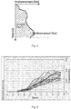
- FIG. 4 schematically represents a insertion torque-displacement curve.
- the insertion torque increases with the insertion depth.
- the course of the curve is not regular and an insertion torque maximum can be identified.
- the insertion torque end value and the amount of the integral can be determined.
- FIG. 5 shows actually measured insertion-torque curves, which were always measured with the same screw foundation model. As can be seen from this figure, the course, integral, maximum and final value can vary greatly depending on the location of the turn.
- the screwing-in time can also be measured during the turning of the screw foundations. This allows the creation of a screw-in torque-time curve. An example of such a curve is in FIG. 6 shown. The phases of the insertion, in which the insertion did not take place regularly, but in which the foundation has slipped, are clearly recognizable. This "slip analysis" can therefore provide additional important information for determining the "worst" screw foundations.
- FIG. 7 shows a graph demonstrating this relationship.
- the amount of insertion torque-integral and the load causing fracture were measured and compared. As can be seen from this graph, there is a high correlation between these values. Based on the torque integral, it is thus possible to identify the "worst" screw foundations, ie the foundations that can carry only a small load.
- FIG. 8 illustrates a preferred embodiment of the inventive method for the soil characterization.
- the method according to the invention begins with the rotation of the test body into a subterranean layer of depth T1. During the recess, the insertion stroke and insertion torque and angular velocity are continuously measured. Subsequently, a insertion torque-displacement curve is created. As shown in this figure, the driving time can be measured and a driving torque-time curve can be created. When the test body has reached the depth T1, a load test is performed and the behavior of the test body (for example, shift amount and shift speed) measured thereby. Based on the insertion torque-displacement curve and the behavior of the test body during the load test, the subsoil layer is characterized by depth T1. As shown in the figure, layer-by-layer soil characterization is repeated until the depth to be characterized has been reached.
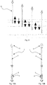
- FIG. 9 illustrates a preferred embodiment of the inventive method for soil characterization. As can be seen in this figure, the test body 10 is gradually screwed into the ground and between two Einfitzen a load test is performed.
- FIGS. 10A and 10B illustrate a preferred embodiment of the inventive device 1 for soil characterization.
- the device 1 comprises a cylindrical part 2 with outer diameter D2 and a conical part 3 with maximum outer diameter D3 and external thread 4.
- the device 1 further comprises a coupling part 5, which coupling the device 1 with a driving machine (not shown here ) with integrated loading device allows.
- the various methods according to the invention can be combined with one another.
- the method of foundation characterization may be applied first, followed by the insertion of screw foundations and the application of the method for determining the screw foundations on which a load test is to be carried out.
- the method according to the invention for subsoil characterization also makes it possible to locate and discover subterranean structures, such as, for example, river courses or subsoil changes due to civilizational activities.
Landscapes
- Engineering & Computer Science (AREA)
- Structural Engineering (AREA)
- Life Sciences & Earth Sciences (AREA)
- General Life Sciences & Earth Sciences (AREA)
- Mining & Mineral Resources (AREA)
- Paleontology (AREA)
- Civil Engineering (AREA)
- General Engineering & Computer Science (AREA)
- Physics & Mathematics (AREA)
- General Physics & Mathematics (AREA)
- Investigation Of Foundation Soil And Reinforcement Of Foundation Soil By Compacting Or Drainage (AREA)
- Force Measurement Appropriate To Specific Purposes (AREA)
Applications Claiming Priority (1)
| Application Number | Priority Date | Filing Date | Title |
|---|---|---|---|
| CH5302018A CH714928A1 (de) | 2018-04-25 | 2018-04-25 | Verfahren zur Belastungsprüfung von Schraubfundamenten sowie Verfahren und Vorrichtung zur Baugrundcharakterisierung. |
Publications (3)
| Publication Number | Publication Date |
|---|---|
| EP3569770A2 true EP3569770A2 (fr) | 2019-11-20 |
| EP3569770A3 EP3569770A3 (fr) | 2020-02-26 |
| EP3569770B1 EP3569770B1 (fr) | 2022-05-25 |
Family
ID=66286267
Family Applications (1)
| Application Number | Title | Priority Date | Filing Date |
|---|---|---|---|
| EP19171176.1A Active EP3569770B1 (fr) | 2018-04-25 | 2019-04-25 | Procédé d'investigation de la capacité des pieux entournés |
Country Status (3)
| Country | Link |
|---|---|
| EP (1) | EP3569770B1 (fr) |
| CH (1) | CH714928A1 (fr) |
| DK (1) | DK3569770T3 (fr) |
Families Citing this family (1)
| Publication number | Priority date | Publication date | Assignee | Title |
|---|---|---|---|---|
| CN118895754B (zh) * | 2024-09-18 | 2025-03-28 | 广东省源天工程有限公司 | 一种提高单桩承载力的打桩方法 |
Family Cites Families (9)
| Publication number | Priority date | Publication date | Assignee | Title |
|---|---|---|---|---|
| US3300988A (en) * | 1960-12-23 | 1967-01-31 | Raymond Int Inc | Apparatus for forming piles |
| DE3617025A1 (de) * | 1986-05-21 | 1987-11-26 | Delmag Maschinenfabrik | Vorgefertigter betonpfahl sowie verfahren und vorrichtung zu seinem einbringen ins erdreich |
| AUPS115402A0 (en) * | 2002-03-18 | 2002-04-18 | Camilleri, Paul Anthony | Screw piles |
| DE10346040A1 (de) * | 2003-10-02 | 2005-05-25 | Bauer Maschinen Gmbh | Verfahren und Prüfanordnung zum Bestimmen des Tragverhaltens von Verdrängungspfählen |
| DE102005045574A1 (de) * | 2005-09-23 | 2007-04-12 | "DOMA"-Autozubehör und Industriebedarf GmbH | Drehfundament zur Verankerung im Erdboden |
| US8033757B2 (en) * | 2006-09-08 | 2011-10-11 | Ben Stroyer | Auger grouted displacement pile |
| DE102008037937A1 (de) * | 2008-08-14 | 2010-02-25 | Krinner Innovation Gmbh | Fundamentsystem zum Ausrichten und Befestigen eines stab- oder pfostenförmigen Gegenstandes im Erdboden sowie Verfahren zum Einbringen eines Kunststoffschraubfundaments in den Erdboden |
| DE102010043785B3 (de) * | 2010-11-11 | 2012-03-22 | Krinner Innovation Gmbh | Schraubfundament mit Abschnitten veränderlicher Durchmesser |
| JP5842046B1 (ja) * | 2014-10-21 | 2016-01-13 | 新日鉄住金エンジニアリング株式会社 | 回転圧入鋼管杭 |
-
2018
- 2018-04-25 CH CH5302018A patent/CH714928A1/de not_active Application Discontinuation
-
2019
- 2019-04-25 EP EP19171176.1A patent/EP3569770B1/fr active Active
- 2019-04-25 DK DK19171176.1T patent/DK3569770T3/da active
Also Published As
| Publication number | Publication date |
|---|---|
| EP3569770B1 (fr) | 2022-05-25 |
| EP3569770A3 (fr) | 2020-02-26 |
| CH714928A1 (de) | 2019-10-31 |
| DK3569770T3 (da) | 2022-08-01 |
Similar Documents
| Publication | Publication Date | Title |
|---|---|---|
| DE102015105908B4 (de) | Bohrgerät zum Erstellen einer verrohrten Bohrung und Verfahren zum Betreiben eines Bohrgerätes | |
| DE2349181A1 (de) | Verfahren und einrichtung zum analysieren von spannungs- und belastungszustaenden | |
| EP3268538B1 (fr) | Procedé de limiter le pression d'un sol d'une machine de travail et machine de travail | |
| EP3960410A1 (fr) | Procédé de détection d'un impact d'armature dans un sous-sol, ainsi qu'appareil de carottage et système de forage | |
| EP3507509B1 (fr) | Capteur de distance sur un bec d'ancre | |
| DE102020211666A1 (de) | Verfahren und Vorrichtung zum Durchführen eines Einschraubprozesses mithilfe Methoden künstlicher Intelligenz | |
| EP3569770B1 (fr) | Procédé d'investigation de la capacité des pieux entournés | |
| DE10346040A1 (de) | Verfahren und Prüfanordnung zum Bestimmen des Tragverhaltens von Verdrängungspfählen | |
| WO2021213723A1 (fr) | Procédé et agencement permettant de surveiller des fondations de bâtiment | |
| EP2439507B1 (fr) | Procédé et dispositif de contrôle de la stabilité d'un système de corde | |
| EP2770306A1 (fr) | Procédé de mesure du niveau d'un liquide dans un puits naturel | |
| EP2762878B1 (fr) | Procédé et dispositif d'analyse contrôlée de la condition de sections des corps cylindriques ou en forme de colonnes | |
| EP3626890B1 (fr) | Procédé d'essai de portance d'une fondation | |
| EP2028473B1 (fr) | Procédé destiné à la recherche et à l'évaluation de la solidité de mâts en bois | |
| EP2050920B1 (fr) | Procédé et dispositif destinés à l'introduction d'un faisceau tubulaire constitué de tuyaux courts dans un canal de forage | |
| DE3928958A1 (de) | Gewindeverbindung von rohrendabschnitten und verfahren zu deren herstellung | |
| EP2898227B1 (fr) | Système d'ancrage comprenant un élément de manchon et un élément à expansion | |
| DE102015100477B4 (de) | Verfahren zum Sondieren von Bodenbereichen im Boden | |
| DE102016110580B3 (de) | Verfahren zur Prüfung der Standfestigkeit eines Masten sowie zugehörige Vorrichtung | |
| EP0606433B1 (fr) | Procede pour la determination de la consistance d'un sous-sol | |
| DE1759425A1 (de) | Verfahren und Vorrichtung zur Bestimmung der mechanischen Eigenschaften und Restspannungen in Gruendungsboeden | |
| DE2346377A1 (de) | Verfahren zum einsetzen von bodenmessgeraeten | |
| DE102007025917B4 (de) | Verfahren und Vorrichtung zur Überprüfung der Umhüllung einer Rohrleitung während des Einzugs in ein mit Flüssigkeit gefülltes Bohrloch | |
| DE4411829A1 (de) | Verfahren zur Ermittlung von bodenmechanischen Kennwerten und Sonde zur Durchführung der Messung | |
| CH705268A2 (de) | Vorrichtung zur Erfassung einer Eigenschaft von Erdreich. |
Legal Events
| Date | Code | Title | Description |
|---|---|---|---|
| PUAI | Public reference made under article 153(3) epc to a published international application that has entered the european phase |
Free format text: ORIGINAL CODE: 0009012 |
|
| STAA | Information on the status of an ep patent application or granted ep patent |
Free format text: STATUS: THE APPLICATION HAS BEEN PUBLISHED |
|
| AK | Designated contracting states |
Kind code of ref document: A2 Designated state(s): AL AT BE BG CH CY CZ DE DK EE ES FI FR GB GR HR HU IE IS IT LI LT LU LV MC MK MT NL NO PL PT RO RS SE SI SK SM TR |
|
| AX | Request for extension of the european patent |
Extension state: BA ME |
|
| PUAL | Search report despatched |
Free format text: ORIGINAL CODE: 0009013 |
|
| AK | Designated contracting states |
Kind code of ref document: A3 Designated state(s): AL AT BE BG CH CY CZ DE DK EE ES FI FR GB GR HR HU IE IS IT LI LT LU LV MC MK MT NL NO PL PT RO RS SE SI SK SM TR |
|
| AX | Request for extension of the european patent |
Extension state: BA ME |
|
| RIC1 | Information provided on ipc code assigned before grant |
Ipc: E02D 33/00 20060101ALI20200122BHEP Ipc: E02D 5/56 20060101AFI20200122BHEP Ipc: E02D 7/22 20060101ALI20200122BHEP Ipc: E02D 13/06 20060101ALI20200122BHEP |
|
| STAA | Information on the status of an ep patent application or granted ep patent |
Free format text: STATUS: REQUEST FOR EXAMINATION WAS MADE |
|
| 17P | Request for examination filed |
Effective date: 20200814 |
|
| RBV | Designated contracting states (corrected) |
Designated state(s): AL AT BE BG CH CY CZ DE DK EE ES FI FR GB GR HR HU IE IS IT LI LT LU LV MC MK MT NL NO PL PT RO RS SE SI SK SM TR |
|
| GRAP | Despatch of communication of intention to grant a patent |
Free format text: ORIGINAL CODE: EPIDOSNIGR1 |
|
| STAA | Information on the status of an ep patent application or granted ep patent |
Free format text: STATUS: GRANT OF PATENT IS INTENDED |
|
| INTG | Intention to grant announced |
Effective date: 20211216 |
|
| GRAS | Grant fee paid |
Free format text: ORIGINAL CODE: EPIDOSNIGR3 |
|
| GRAA | (expected) grant |
Free format text: ORIGINAL CODE: 0009210 |
|
| STAA | Information on the status of an ep patent application or granted ep patent |
Free format text: STATUS: THE PATENT HAS BEEN GRANTED |
|
| AK | Designated contracting states |
Kind code of ref document: B1 Designated state(s): AL AT BE BG CH CY CZ DE DK EE ES FI FR GB GR HR HU IE IS IT LI LT LU LV MC MK MT NL NO PL PT RO RS SE SI SK SM TR |
|
| REG | Reference to a national code |
Ref country code: GB Ref legal event code: FG4D Free format text: NOT ENGLISH |
|
| REG | Reference to a national code |
Ref country code: CH Ref legal event code: EP |
|
| REG | Reference to a national code |
Ref country code: AT Ref legal event code: REF Ref document number: 1494310 Country of ref document: AT Kind code of ref document: T Effective date: 20220615 Ref country code: DE Ref legal event code: R096 Ref document number: 502019004432 Country of ref document: DE |
|
| REG | Reference to a national code |
Ref country code: IE Ref legal event code: FG4D Free format text: LANGUAGE OF EP DOCUMENT: GERMAN |
|
| REG | Reference to a national code |
Ref country code: DK Ref legal event code: T3 Effective date: 20220729 |
|
| REG | Reference to a national code |
Ref country code: NL Ref legal event code: FP |
|
| REG | Reference to a national code |
Ref country code: SE Ref legal event code: TRGR |
|
| REG | Reference to a national code |
Ref country code: LT Ref legal event code: MG9D |
|
| REG | Reference to a national code |
Ref country code: NO Ref legal event code: T2 Effective date: 20220525 |
|
| PG25 | Lapsed in a contracting state [announced via postgrant information from national office to epo] |
Ref country code: PT Free format text: LAPSE BECAUSE OF FAILURE TO SUBMIT A TRANSLATION OF THE DESCRIPTION OR TO PAY THE FEE WITHIN THE PRESCRIBED TIME-LIMIT Effective date: 20220926 Ref country code: LT Free format text: LAPSE BECAUSE OF FAILURE TO SUBMIT A TRANSLATION OF THE DESCRIPTION OR TO PAY THE FEE WITHIN THE PRESCRIBED TIME-LIMIT Effective date: 20220525 Ref country code: HR Free format text: LAPSE BECAUSE OF FAILURE TO SUBMIT A TRANSLATION OF THE DESCRIPTION OR TO PAY THE FEE WITHIN THE PRESCRIBED TIME-LIMIT Effective date: 20220525 Ref country code: GR Free format text: LAPSE BECAUSE OF FAILURE TO SUBMIT A TRANSLATION OF THE DESCRIPTION OR TO PAY THE FEE WITHIN THE PRESCRIBED TIME-LIMIT Effective date: 20220826 Ref country code: FI Free format text: LAPSE BECAUSE OF FAILURE TO SUBMIT A TRANSLATION OF THE DESCRIPTION OR TO PAY THE FEE WITHIN THE PRESCRIBED TIME-LIMIT Effective date: 20220525 Ref country code: ES Free format text: LAPSE BECAUSE OF FAILURE TO SUBMIT A TRANSLATION OF THE DESCRIPTION OR TO PAY THE FEE WITHIN THE PRESCRIBED TIME-LIMIT Effective date: 20220525 Ref country code: BG Free format text: LAPSE BECAUSE OF FAILURE TO SUBMIT A TRANSLATION OF THE DESCRIPTION OR TO PAY THE FEE WITHIN THE PRESCRIBED TIME-LIMIT Effective date: 20220825 |
|
| PG25 | Lapsed in a contracting state [announced via postgrant information from national office to epo] |
Ref country code: RS Free format text: LAPSE BECAUSE OF FAILURE TO SUBMIT A TRANSLATION OF THE DESCRIPTION OR TO PAY THE FEE WITHIN THE PRESCRIBED TIME-LIMIT Effective date: 20220525 Ref country code: PL Free format text: LAPSE BECAUSE OF FAILURE TO SUBMIT A TRANSLATION OF THE DESCRIPTION OR TO PAY THE FEE WITHIN THE PRESCRIBED TIME-LIMIT Effective date: 20220525 Ref country code: LV Free format text: LAPSE BECAUSE OF FAILURE TO SUBMIT A TRANSLATION OF THE DESCRIPTION OR TO PAY THE FEE WITHIN THE PRESCRIBED TIME-LIMIT Effective date: 20220525 Ref country code: IS Free format text: LAPSE BECAUSE OF FAILURE TO SUBMIT A TRANSLATION OF THE DESCRIPTION OR TO PAY THE FEE WITHIN THE PRESCRIBED TIME-LIMIT Effective date: 20220925 |
|
| PG25 | Lapsed in a contracting state [announced via postgrant information from national office to epo] |
Ref country code: SM Free format text: LAPSE BECAUSE OF FAILURE TO SUBMIT A TRANSLATION OF THE DESCRIPTION OR TO PAY THE FEE WITHIN THE PRESCRIBED TIME-LIMIT Effective date: 20220525 Ref country code: SK Free format text: LAPSE BECAUSE OF FAILURE TO SUBMIT A TRANSLATION OF THE DESCRIPTION OR TO PAY THE FEE WITHIN THE PRESCRIBED TIME-LIMIT Effective date: 20220525 Ref country code: RO Free format text: LAPSE BECAUSE OF FAILURE TO SUBMIT A TRANSLATION OF THE DESCRIPTION OR TO PAY THE FEE WITHIN THE PRESCRIBED TIME-LIMIT Effective date: 20220525 Ref country code: EE Free format text: LAPSE BECAUSE OF FAILURE TO SUBMIT A TRANSLATION OF THE DESCRIPTION OR TO PAY THE FEE WITHIN THE PRESCRIBED TIME-LIMIT Effective date: 20220525 Ref country code: CZ Free format text: LAPSE BECAUSE OF FAILURE TO SUBMIT A TRANSLATION OF THE DESCRIPTION OR TO PAY THE FEE WITHIN THE PRESCRIBED TIME-LIMIT Effective date: 20220525 |
|
| REG | Reference to a national code |
Ref country code: DE Ref legal event code: R097 Ref document number: 502019004432 Country of ref document: DE |
|
| PG25 | Lapsed in a contracting state [announced via postgrant information from national office to epo] |
Ref country code: AL Free format text: LAPSE BECAUSE OF FAILURE TO SUBMIT A TRANSLATION OF THE DESCRIPTION OR TO PAY THE FEE WITHIN THE PRESCRIBED TIME-LIMIT Effective date: 20220525 |
|
| PLBE | No opposition filed within time limit |
Free format text: ORIGINAL CODE: 0009261 |
|
| STAA | Information on the status of an ep patent application or granted ep patent |
Free format text: STATUS: NO OPPOSITION FILED WITHIN TIME LIMIT |
|
| 26N | No opposition filed |
Effective date: 20230228 |
|
| PG25 | Lapsed in a contracting state [announced via postgrant information from national office to epo] |
Ref country code: SI Free format text: LAPSE BECAUSE OF FAILURE TO SUBMIT A TRANSLATION OF THE DESCRIPTION OR TO PAY THE FEE WITHIN THE PRESCRIBED TIME-LIMIT Effective date: 20220525 |
|
| PG25 | Lapsed in a contracting state [announced via postgrant information from national office to epo] |
Ref country code: LU Free format text: LAPSE BECAUSE OF NON-PAYMENT OF DUE FEES Effective date: 20230425 |
|
| REG | Reference to a national code |
Ref country code: BE Ref legal event code: MM Effective date: 20230430 |
|
| PG25 | Lapsed in a contracting state [announced via postgrant information from national office to epo] |
Ref country code: MC Free format text: LAPSE BECAUSE OF FAILURE TO SUBMIT A TRANSLATION OF THE DESCRIPTION OR TO PAY THE FEE WITHIN THE PRESCRIBED TIME-LIMIT Effective date: 20220525 |
|
| PG25 | Lapsed in a contracting state [announced via postgrant information from national office to epo] |
Ref country code: MC Free format text: LAPSE BECAUSE OF FAILURE TO SUBMIT A TRANSLATION OF THE DESCRIPTION OR TO PAY THE FEE WITHIN THE PRESCRIBED TIME-LIMIT Effective date: 20220525 Ref country code: IT Free format text: LAPSE BECAUSE OF FAILURE TO SUBMIT A TRANSLATION OF THE DESCRIPTION OR TO PAY THE FEE WITHIN THE PRESCRIBED TIME-LIMIT Effective date: 20220525 |
|
| REG | Reference to a national code |
Ref country code: IE Ref legal event code: MM4A |
|
| PG25 | Lapsed in a contracting state [announced via postgrant information from national office to epo] |
Ref country code: BE Free format text: LAPSE BECAUSE OF NON-PAYMENT OF DUE FEES Effective date: 20230430 |
|
| PG25 | Lapsed in a contracting state [announced via postgrant information from national office to epo] |
Ref country code: IE Free format text: LAPSE BECAUSE OF NON-PAYMENT OF DUE FEES Effective date: 20230425 |
|
| PG25 | Lapsed in a contracting state [announced via postgrant information from national office to epo] |
Ref country code: IE Free format text: LAPSE BECAUSE OF NON-PAYMENT OF DUE FEES Effective date: 20230425 |
|
| PG25 | Lapsed in a contracting state [announced via postgrant information from national office to epo] |
Ref country code: BG Free format text: LAPSE BECAUSE OF FAILURE TO SUBMIT A TRANSLATION OF THE DESCRIPTION OR TO PAY THE FEE WITHIN THE PRESCRIBED TIME-LIMIT Effective date: 20220525 |
|
| PG25 | Lapsed in a contracting state [announced via postgrant information from national office to epo] |
Ref country code: BG Free format text: LAPSE BECAUSE OF FAILURE TO SUBMIT A TRANSLATION OF THE DESCRIPTION OR TO PAY THE FEE WITHIN THE PRESCRIBED TIME-LIMIT Effective date: 20220525 |
|
| PGFP | Annual fee paid to national office [announced via postgrant information from national office to epo] |
Ref country code: CH Payment date: 20250501 Year of fee payment: 7 |
|
| PG25 | Lapsed in a contracting state [announced via postgrant information from national office to epo] |
Ref country code: CY Free format text: LAPSE BECAUSE OF FAILURE TO SUBMIT A TRANSLATION OF THE DESCRIPTION OR TO PAY THE FEE WITHIN THE PRESCRIBED TIME-LIMIT; INVALID AB INITIO Effective date: 20190425 |
|
| PG25 | Lapsed in a contracting state [announced via postgrant information from national office to epo] |
Ref country code: HU Free format text: LAPSE BECAUSE OF FAILURE TO SUBMIT A TRANSLATION OF THE DESCRIPTION OR TO PAY THE FEE WITHIN THE PRESCRIBED TIME-LIMIT; INVALID AB INITIO Effective date: 20190425 |
|
| PGFP | Annual fee paid to national office [announced via postgrant information from national office to epo] |
Ref country code: NL Payment date: 20250721 Year of fee payment: 7 |
|
| PGFP | Annual fee paid to national office [announced via postgrant information from national office to epo] |
Ref country code: DE Payment date: 20250722 Year of fee payment: 7 Ref country code: DK Payment date: 20250710 Year of fee payment: 7 |
|
| PGFP | Annual fee paid to national office [announced via postgrant information from national office to epo] |
Ref country code: NO Payment date: 20250711 Year of fee payment: 7 |
|
| PGFP | Annual fee paid to national office [announced via postgrant information from national office to epo] |
Ref country code: FR Payment date: 20250722 Year of fee payment: 7 Ref country code: AT Payment date: 20250722 Year of fee payment: 7 |
|
| PGFP | Annual fee paid to national office [announced via postgrant information from national office to epo] |
Ref country code: SE Payment date: 20250722 Year of fee payment: 7 |
|
| PG25 | Lapsed in a contracting state [announced via postgrant information from national office to epo] |
Ref country code: TR Free format text: LAPSE BECAUSE OF FAILURE TO SUBMIT A TRANSLATION OF THE DESCRIPTION OR TO PAY THE FEE WITHIN THE PRESCRIBED TIME-LIMIT Effective date: 20220525 |
|
| PGFP | Annual fee paid to national office [announced via postgrant information from national office to epo] |
Ref country code: GB Payment date: 20260324 Year of fee payment: 8 |
|
| REG | Reference to a national code |
Ref country code: CH Ref legal event code: U11 Free format text: ST27 STATUS EVENT CODE: U-0-0-U10-U11 (AS PROVIDED BY THE NATIONAL OFFICE) Effective date: 20260501 |