EP3569535A1 - Method for peeling protective sheet for prepreg sheet, and apparatus for peeling protective sheet for prepreg sheet - Google Patents
Method for peeling protective sheet for prepreg sheet, and apparatus for peeling protective sheet for prepreg sheet Download PDFInfo
- Publication number
- EP3569535A1 EP3569535A1 EP18763459.7A EP18763459A EP3569535A1 EP 3569535 A1 EP3569535 A1 EP 3569535A1 EP 18763459 A EP18763459 A EP 18763459A EP 3569535 A1 EP3569535 A1 EP 3569535A1
- Authority
- EP
- European Patent Office
- Prior art keywords
- sheet
- prepreg
- prepreg sheet
- protective sheet
- peeling
- Prior art date
- Legal status (The legal status is an assumption and is not a legal conclusion. Google has not performed a legal analysis and makes no representation as to the accuracy of the status listed.)
- Withdrawn
Links
- 230000001681 protective effect Effects 0.000 title claims abstract description 113
- 238000000034 method Methods 0.000 title claims abstract description 15
- 239000000835 fiber Substances 0.000 claims abstract description 51
- 230000003116 impacting effect Effects 0.000 claims description 2
- 238000010586 diagram Methods 0.000 description 15
- 230000002349 favourable effect Effects 0.000 description 12
- 238000010030 laminating Methods 0.000 description 9
- 229920005989 resin Polymers 0.000 description 6
- 239000011347 resin Substances 0.000 description 6
- 239000000463 material Substances 0.000 description 4
- 230000000694 effects Effects 0.000 description 3
- 230000008569 process Effects 0.000 description 3
- 230000007480 spreading Effects 0.000 description 3
- 239000004918 carbon fiber reinforced polymer Substances 0.000 description 2
- 238000005516 engineering process Methods 0.000 description 2
- 230000007246 mechanism Effects 0.000 description 2
- 229920000728 polyester Polymers 0.000 description 2
- 229920000139 polyethylene terephthalate Polymers 0.000 description 2
- 239000005020 polyethylene terephthalate Substances 0.000 description 2
- 229920001187 thermosetting polymer Polymers 0.000 description 2
- -1 Polyethylene Terephthalate Polymers 0.000 description 1
- 238000007792 addition Methods 0.000 description 1
- 239000002131 composite material Substances 0.000 description 1
- 230000005611 electricity Effects 0.000 description 1
- 230000006872 improvement Effects 0.000 description 1
- 238000012986 modification Methods 0.000 description 1
- 230000004048 modification Effects 0.000 description 1
- 230000002093 peripheral effect Effects 0.000 description 1
- 230000009467 reduction Effects 0.000 description 1
- 230000003068 static effect Effects 0.000 description 1
- 238000006467 substitution reaction Methods 0.000 description 1
Images




Classifications
-
- B—PERFORMING OPERATIONS; TRANSPORTING
- B29—WORKING OF PLASTICS; WORKING OF SUBSTANCES IN A PLASTIC STATE IN GENERAL
- B29C—SHAPING OR JOINING OF PLASTICS; SHAPING OF MATERIAL IN A PLASTIC STATE, NOT OTHERWISE PROVIDED FOR; AFTER-TREATMENT OF THE SHAPED PRODUCTS, e.g. REPAIRING
- B29C70/00—Shaping composites, i.e. plastics material comprising reinforcements, fillers or preformed parts, e.g. inserts
- B29C70/04—Shaping composites, i.e. plastics material comprising reinforcements, fillers or preformed parts, e.g. inserts comprising reinforcements only, e.g. self-reinforcing plastics
- B29C70/28—Shaping operations therefor
- B29C70/54—Component parts, details or accessories; Auxiliary operations, e.g. feeding or storage of prepregs or SMC after impregnation or during ageing
-
- B—PERFORMING OPERATIONS; TRANSPORTING
- B29—WORKING OF PLASTICS; WORKING OF SUBSTANCES IN A PLASTIC STATE IN GENERAL
- B29B—PREPARATION OR PRETREATMENT OF THE MATERIAL TO BE SHAPED; MAKING GRANULES OR PREFORMS; RECOVERY OF PLASTICS OR OTHER CONSTITUENTS OF WASTE MATERIAL CONTAINING PLASTICS
- B29B13/00—Conditioning or physical treatment of the material to be shaped
-
- B—PERFORMING OPERATIONS; TRANSPORTING
- B32—LAYERED PRODUCTS
- B32B—LAYERED PRODUCTS, i.e. PRODUCTS BUILT-UP OF STRATA OF FLAT OR NON-FLAT, e.g. CELLULAR OR HONEYCOMB, FORM
- B32B43/00—Operations specially adapted for layered products and not otherwise provided for, e.g. repairing; Apparatus therefor
- B32B43/006—Delaminating
-
- B—PERFORMING OPERATIONS; TRANSPORTING
- B65—CONVEYING; PACKING; STORING; HANDLING THIN OR FILAMENTARY MATERIAL
- B65H—HANDLING THIN OR FILAMENTARY MATERIAL, e.g. SHEETS, WEBS, CABLES
- B65H41/00—Machines for separating superposed webs
-
- B—PERFORMING OPERATIONS; TRANSPORTING
- B32—LAYERED PRODUCTS
- B32B—LAYERED PRODUCTS, i.e. PRODUCTS BUILT-UP OF STRATA OF FLAT OR NON-FLAT, e.g. CELLULAR OR HONEYCOMB, FORM
- B32B2305/00—Condition, form or state of the layers or laminate
- B32B2305/07—Parts immersed or impregnated in a matrix
- B32B2305/076—Prepregs
-
- B—PERFORMING OPERATIONS; TRANSPORTING
- B32—LAYERED PRODUCTS
- B32B—LAYERED PRODUCTS, i.e. PRODUCTS BUILT-UP OF STRATA OF FLAT OR NON-FLAT, e.g. CELLULAR OR HONEYCOMB, FORM
- B32B38/00—Ancillary operations in connection with laminating processes
- B32B38/10—Removing layers, or parts of layers, mechanically or chemically
-
- Y—GENERAL TAGGING OF NEW TECHNOLOGICAL DEVELOPMENTS; GENERAL TAGGING OF CROSS-SECTIONAL TECHNOLOGIES SPANNING OVER SEVERAL SECTIONS OF THE IPC; TECHNICAL SUBJECTS COVERED BY FORMER USPC CROSS-REFERENCE ART COLLECTIONS [XRACs] AND DIGESTS
- Y10—TECHNICAL SUBJECTS COVERED BY FORMER USPC
- Y10T—TECHNICAL SUBJECTS COVERED BY FORMER US CLASSIFICATION
- Y10T156/00—Adhesive bonding and miscellaneous chemical manufacture
- Y10T156/11—Methods of delaminating, per se; i.e., separating at bonding face
- Y10T156/1126—Using direct fluid current against work during delaminating
- Y10T156/1137—Using air blast directly against work during delaminating
-
- Y—GENERAL TAGGING OF NEW TECHNOLOGICAL DEVELOPMENTS; GENERAL TAGGING OF CROSS-SECTIONAL TECHNOLOGIES SPANNING OVER SEVERAL SECTIONS OF THE IPC; TECHNICAL SUBJECTS COVERED BY FORMER USPC CROSS-REFERENCE ART COLLECTIONS [XRACs] AND DIGESTS
- Y10—TECHNICAL SUBJECTS COVERED BY FORMER USPC
- Y10T—TECHNICAL SUBJECTS COVERED BY FORMER US CLASSIFICATION
- Y10T156/00—Adhesive bonding and miscellaneous chemical manufacture
- Y10T156/11—Methods of delaminating, per se; i.e., separating at bonding face
- Y10T156/1168—Gripping and pulling work apart during delaminating
-
- Y—GENERAL TAGGING OF NEW TECHNOLOGICAL DEVELOPMENTS; GENERAL TAGGING OF CROSS-SECTIONAL TECHNOLOGIES SPANNING OVER SEVERAL SECTIONS OF THE IPC; TECHNICAL SUBJECTS COVERED BY FORMER USPC CROSS-REFERENCE ART COLLECTIONS [XRACs] AND DIGESTS
- Y10—TECHNICAL SUBJECTS COVERED BY FORMER USPC
- Y10T—TECHNICAL SUBJECTS COVERED BY FORMER US CLASSIFICATION
- Y10T156/00—Adhesive bonding and miscellaneous chemical manufacture
- Y10T156/19—Delaminating means
- Y10T156/1928—Differential fluid pressure delaminating means
- Y10T156/1933—Spraying delaminating means [e.g., atomizer, etc.
- Y10T156/1939—Air blasting delaminating means]
Definitions
- the present embodiment is concerning a method of peeling protective sheet from prepreg sheet and an apparatus for peeling to be used therein.
- Body, main wings and the like of aircrafts are manufactured by use of prepreg laminate bodies configured by laminating a plurality of prepreg sheets which are punched thin plates of Carbon Fiber Reinforced Plastics (CFRP) or the like.
- CFRP Carbon Fiber Reinforced Plastics
- each prepreg sheet is manufactured by impregnating a fiber sheet, in which a plurality of fibers is arranged in parallel, with a UV curable resin, thermosetting resin or the like in a semi-cured state which are not completely cured and have tackiness. Therefore, one surface or both surfaces of the prepreg sheet is/are attached with a protective sheet, because of the tackiness.
- fibers which form one prepreg sheet are arranged aligned in a single direction, in a fiber direction in which the fibers extend.
- the prepreg laminate body is manufactured by removing the protective sheet from the prepreg sheet, spreading prepreg sheets in a first layer of the prepreg laminate body, then spreading prepreg sheets in a second layer similarly and laminating a plurality of layers of prepreg sheets.
- fiber directions in two adjacently laminated prepreg sheets cross in a prepreg laminate body that requires a material strength.
- a prepreg sheet with a fiber direction oriented in 0 degree direction is laminated with another prepreg sheet with a fiber direction oriented in 45 degrees or 90 degrees thereon, and a plurality of prepreg sheets are laminated by crossing fiber directions.
- the prepreg laminating apparatus disclosed in the patent literature 1 is provided with a first roller, a second roller and a means for peeling release paper in advance and is used to laminate a plurality of prepreg sheets, in which fiber sheets are impregnated with a resin, to form a prepreg laminate body.
- a protective sheet is attached on one surface of the prepreg sheet and the prepreg laminating apparatus has a function of peeling the protective sheet.
- the first roller is arranged in a front-rear direction of a body to be laminated and guides the prepreg sheet in a single direction.
- the second roller presses the prepreg sheet having passed the first roller from one surface thereof and guides the protective sheet in order to peel from the one surface of the prepreg sheet, so that the protective sheet is peeled.
- the prepreg laminating apparatus disclosed in the patent literature 1 has a process of sandwiching the prepreg sheet attached with the protective sheet and tear the protective sheet off while pressing, in order to peel the protective sheet from the prepreg sheet.
- the prepreg sheet is vulnerable to excessive pressure because formed by impregnating with a resin in semi-cured state, and therefore the prepreg sheet may be damaged while tearing-off process.
- peeling effect is weak and limited in peeling technology using rollers and effective peeling technologies are required.
- the present invention aims to provide a method of peeling a protective sheet from a prepreg sheet more efficiently without damaging the prepreg sheet, and an apparatus for peeling to be used therein.
- an apparatus for peeling a protective sheet from a prepreg sheet is provided with a mounting table, a movable arm, a peeling trigger section and a peeling section.
- the movable arm holds a prepreg sheet attached with the protective sheet to move the prepreg sheet on the mounting table and arranges the prepreg sheet so that an edge section of both the prepreg sheet and the protective sheet overhangs the mounting table.
- the peeling trigger section impacts a part of the prepreg sheet and the protective sheet which overhangs the mounting table so that at least a part of the protective sheet is peeled from the prepreg sheet.
- the peeling section holds by suction the protective sheet and completely peels the protective sheet from the prepreg sheet.
- a method of peeling a protective sheet from a prepreg sheet includes a step of determining a fiber direction of a prepreg sheet, a step of physically impacting a protective sheet attached to the prepreg sheet from a direction to bend fibers of the prepreg sheet, to partially peel the protective sheet from the prepreg sheet and a step of holding and moving the partially peeled protective sheet to peel the protective sheet from the entire surface of the prepreg sheet.
- a protective sheet can be peeled effectively, without damaging a prepreg sheet attached with the protective sheet.
- a prepreg sheet to be processed by the apparatus for peeling protective sheet from prepreg sheet according to an embodiment of the present invention is formed by impregnating a fiber sheet, in which a plurality of fibers are arranged by aligning a fiber direction, with a Ultra Violet (UV) curable resin, a thermosetting resin or the like in a semi-cured state.
- a protective sheet consisting of Polyethylene Terephthalate (PET), Polyester (PEs) or the like.
- PET Polyethylene Terephthalate
- PET Polyethylene Terephthalate
- PEs Polyester
- a prepreg laminate body which is a material for composite material, is formed by laminating a plurality of prepreg sheet layers.
- a first prepreg sheet layer is formed by removing protective sheet from each prepreg sheet and by arranging a plurality of prepreg sheets in parallel to spread on a flat surface.
- Fig. 1A is a top view schematically showing an example of a shape of a prepreg sheet 50 used in the present invention.
- the first layer of the prepreg laminate body in which a fiber direction 54 of the prepreg sheet 50 is arranged in 45 degrees with respect to a given planar coordinate system, is formed by spreading prepreg sheets with a parallelogram shape (first pieces 51), a prepreg sheet of trapezoid shape (second piece 52) and a prepreg sheet of triangle shape (third piece 53).
- Fig. 1B is a diagram showing a configuration example of a prepreg laminate body 100.
- the prepreg laminate body 100 is manufactured by forming a prepreg sheet 60 as a second layer of the prepreg laminate body 100, a prepreg sheet 70 as a third layer of the same and a prepreg sheet 80 as a fourth layer, similarly to the prepreg sheet 50 as a first layer of the prepreg laminate body 100, and by sequentially laminating those prepreg sheets 50, 60, 70 and 80.
- the fiber direction 54 of the prepreg sheet 50 of the first layer and a fiber direction 64 of the prepreg sheet 60 of the second layer are different.
- a prepreg sheet with a fiber direction of 0 degree another prepreg sheet with a fiber direction of 45 degrees or 90 degrees is laminated, and so on, a plurality of prepreg sheets are laminated so that respective fiber direction cross.
- an outer peripheral part of the prepreg sheet 50 will be called edge section 55
- vertex part of the edge section 55 in particular will be called corner section 56.
- Fig. 1C is a top view showing an example of positional relationship of a prepreg sheet 50, edge sections 55 and corner sections 56.
- Fig. 2 is a diagram showing an example of an overall configuration of an apparatus 1 for peeling protective sheet from prepreg sheet according to an embodiment of the present invention.
- the apparatus 1 for peeling protective sheet from prepreg sheet is provided with a movable arm 12, which holds and moves a prepreg sheet attached with a protective sheet, a mounting table 13, on which the prepreg sheet attached with the protective sheet is placed, a peeling trigger section 14, which physically impacts the prepreg sheet attached with the protective sheet and partially peels the protective sheet from the prepreg sheet to trigger peeling of the protective sheet, and a peeling section 15, which holds and moves the protective sheet partially peeled from the prepreg sheet to peel the protective sheet from the entire surface of the prepreg sheet.
- the movable arm 12 is provided with a hand section 121, which hold the prepreg sheet, a movable section 122, which moves the prepreg sheet held by the hand section 121 to the mounting table 13, and a control section 16.
- a hand section 121 which hold the prepreg sheet
- a movable section 122 which moves the prepreg sheet held by the hand section 121 to the mounting table 13, and a control section 16.
- a hand section 121 which holds the prepreg sheet
- a movable section 122 which moves the prepreg sheet held by the hand section 121 to the mounting table 13
- a control section 16 In the configuration example in Fig. 2 , a same configuration is used as the hand section 121 and as the peeling section 15.
- the peeling trigger section 14 is provided with a motor 141, a rotation shaft 142 and wing section 143, 144.
- the control section 16 is provided with a determination section 161.
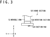
- Fig. 3 is a diagram showing an essential part of a hand section 121 of a movable arm 12 according to an embodiment of the present invention.
- the hand section 121 is provided with a suction pad 123 and a rotation section 124.
- the suction pad 123 makes a surface of the suction pad 123 in a vacuum state, by use of a non-illustrated vacuum ejector, to enable a sheet-shaped target object in contact with the suction pad 123 to be held by suction thereon.
- the movable sections 122 in Fig. 2 are connected to the hand section 121 to support the hand sections 121 and are able to freely move the hand section 121 in a vertical direction and in a horizontal direction.
- the rotation section 124 is able to rotate the held prepreg sheet 50 in 360 degrees in horizontal plane, by rotating the suction pad 123.
- moves of the movable arm 12 in horizontal direction, vertical direction and rotation direction are able to drive the movable sections 122 in accordance with the control section 16 provided in the movable arm 12, and arrange the prepreg sheet 50 held by the hand section 121, by freely controlling a position and an angle with respect to the mounting table 13.
- the control section 16 is further provided with a determination section 161, which determines a fiber direction 54 of fibers that the prepreg sheet 50 contains, and is able to freely control the position and the angle of the prepreg sheet 50 with respect to the mounting table 13, in accordance with the determination result of the fiber direction 54.
- the determination of the fiber direction 54 may be performed, for example, by use of a Charge Coupled Device (CCD) camera and an image recognition processing device which are not illustrated.
- the image recognition processing device may be a computer which is provided with a processing device, a memory device and various interfaces and executes given programs.
- various prepreg sheets are formed in different shapes respectively to fiber directions thereof. Data showing relationship between shapes and fiber directions of the prepreg sheets may be stored in the memory device of the image recognition processing device. In the example of Fig.
- the prepreg sheet 50 of which the fiber direction 54 is in 45 degrees with respect to the planar coordinate system OXY
- the prepreg sheet 70 of which the fiber direction 74 is in -45 degrees with respect to the same coordinate system, both have a parallelogram shape.
- each part of the prepreg sheet 80, of which the fiber direction 84 is 0 degree with respect to the planar coordinate system OXY, and each part of the prepreg sheet 60, of which the fiber direction 64 is 90 degrees with respect to the same coordinate system both have a rectangular shape and share a feature in which the longitudinal direction thereof is identical to the fiber direction thereof, while can be distinguished by sizes and aspect ratios thereof.
- the relationship between shapes of the prepreg sheets 50, 60, 70, 80 and the fiber directions 54, 64, 74, 84 is so that the latter ones can be determined by distinguishing the former ones.
- the CCD camera takes images of prepreg sheet shapes to generate image data.
- the image recognition processing device executes an image recognition processing software and processes image data to determine which among the above four kinds the shape of the imaged prepreg sheet is.
- the image recognition processing device is able to determine the fiber direction of the prepreg sheet by referring data showing relationship between the determined shape and fiber direction of the prepreg sheet.
- the hand section 121 may be provided with a configuration, other than a suction member, to hold the prepreg sheet 50 by sandwiching for example, and in addition, may use further other member as long as such configuration can grip the sheet.
- the control section 16 and the determination section 161 do not need to be provided integrated to the movable arm 12, and may be provided as a new mechanism having the control section 16 and the determination section 161 separately.
- the mounting table 13 has a flat plate shape able to horizontally support the prepreg sheet 50 at any position, and a prepreg sheet 50, which is held and moved by the movable arm 12 and to which the protective sheet 40 is attached with, is placed thereon.
- the prepreg sheet 50 is placed on the mounting table 13 with the protective sheet 40 to be peeled as the top surface.
- the position of the prepreg sheet 50 with respect to the mounting table 13 may be easily fixed, by the tackiness of the bottom surface of the prepreg sheet 50.
- the prepreg sheet 50 is arranged so that a part of the edge section 55 or the corner section 56 of the prepreg sheet 50 overhangs the edge section 131 of the mounting table 13.
- the part of the prepreg sheet 50 overhanging the edge section 131 of the mounting table 13 is used as an impact tip 57 for the peeling trigger section 14 to physically impact the prepreg sheet 50.
- the mounting table 13 may be provided with a holding device to hold the prepreg sheet 50, a mechanism to hold the prepreg sheet 50 by a vacuum suction or static electricity, or the like.
- the peeling trigger section 14 directly and physically impacts the protective sheet 40 in the part of impact tip 57, of the prepreg sheet 50 placed on the mounting table 13 in a state in which the protective sheet 40 is attached with on the top surface thereof, to cause a partial peeling between the protective sheet 40 and the prepreg sheet 50.
- Fig. 4A is a diagram showing an essential part of a peeling trigger section 14 according to an embodiment of the present invention.
- the peeling trigger section 14 in Fig. 4A is provided with the motor 141 in Fig. 2 , a rotation shaft 142 which rotates by a power of the motor 141 and the first wing section 143 and the second wing section 144 provided to the rotation shaft 142.
- the rotation shaft 142 to which a power of the motor 141 is transmitted, is arranged at a position in which the wing sections 143 and 144, which rotate together with the rotation shaft 142, can physically impact a part of the impact tip 57 of the prepreg sheet 50 and the protective sheet 40, directly.
- the rotation shaft 142 may be integrated to a rotation shaft of the motor 141, or may be a rotation shaft 142 which is transmitted with a power from the rotation shaft of the motor 141 to separately rotate.
- the inventors of the present invention have found out that, when partially peeling the protective sheet 40 from the prepreg sheet 50, an effect of partially peeling the protective sheet 40 is enhanced by arranging the edge section 55 or the corner section 56 of the prepreg sheet 50 and the protective sheet 40, with an overhanging from the edge section 131 of the mounting table 13 by a given length, as the impact tip 57.
- the length of the impact tip 57 is set between 20mm and 30mm to effectively peel the protective sheet 40.
- fibers in one prepreg sheet 50 is arranged in one substantially same direction; however, the inventors of the present invention have found out that, when performing the peeling of the protective sheet 40 from the prepreg sheet 50, the effect of peeling the protective sheet is enhanced by satisfying following three conditions.
- each of the edge section 131 of the mounting table 13, which the impact tip 57 overhangs, and edge sections of the wing section 143, 144 has a substantially linear shape, and, the edge sections of the wing sections 143, 144 and the edge section 131 of the mounting table 13 are in parallel at the moment the wing sections 143, 144 impact the impact tip 57.
- a gap 58 from the edge sections of the wing sections 143, 144 to the edge section 131 of the mounting table 13 is short enough at the moment the wing sections 143, 144 impact the impact tip 57.
- Fig. 4B is a diagram showing an example of a gap 58 according to the present embodiment. Concerning the second condition, the length of the gap 58 is favorably longer than 1mm and shorter than 2.5mm.
- Fig. 4C is a diagram showing an example of an edge side direction 132 according to the present embodiment.
- Fig. 4D is a diagram showing an example of a crossing angle 59 according to the present embodiment.
- the crossing angle 59 between the edge side direction 132 of the edge section 131 of the mounting table 13 and the fiber direction 54 of the prepreg sheet 50 is large enough.
- This third condition means in other words that the prepreg sheet 50 is arranged with respect to the mounting table 13 so that the physical impact from the wing sections 143, 144 of the peeling trigger section 14 is added in a direction to bend fibers of the prepreg sheet 50.
- the apparatus 1 for peeling a protective sheet 40 from a prepreg sheet 50 firstly determines the fiber direction 54 of the prepreg sheet 50 by the determination section 161.
- the control section 16 controls the direction of the hand section 121 of the movable arm 12 by appropriately rotating the movable sections 122 and the rotation section 124, so that the crossing angle 59 between the fiber direction 54 of the prepreg sheet 50 and the edge side direction 132 of the edge section 131 of the mounting table 13 is included in a favorable range.
- the apparatus 1 for peeling the protective sheet 40 from the prepreg sheet 50 according to the present embodiment can place the prepreg sheet 50 attached with the protective sheet 40 on the mounting table 13 with a favorable position and a favorable angle both relative to the edge section 131.
- the crossing angle 59 between the fiber direction 54 of the prepreg sheet 50 and the edge side direction 132 is included in a range between 10 degrees and 170 degrees.
- This crossing angle 59 is preferably included in a range between 30 degrees and 150 degrees, is further preferably included in a range between 60 degrees and 120 degrees, and ideally equals to 90 degrees.
- each of the wing sections 143, 144 is a thin plate in a shape of a rectangle consisting of an elastic body such as a rubber, for example, and is arranged so that a short side of the rectangle is along the rotation shaft 142.
- the wing sections 143, 144 provided on the rotation shaft 142 may be single or plural.
- the shape of each of the wing sections 143, 144 is favorably a shape of a rectangle with a long side of 60mm and a thickness of 2mm.
- wing sections 143, 144 in the present invention is not limited to have a thin plate of a rectangular shape and may have any shape as long as it can physically impact the impact tip 57 of the prepreg sheet 50 and the protective sheet 40 overhanging the mounting table.
- the peeling section 15 completely peels the protective sheet 40 from an entire surface of the prepreg sheet 50 by holding and moving a part of the protective sheet 40 partially peeled from the prepreg sheet 50.
- the apparatus 1 for peeling the protective sheet 40 from the prepreg sheet 50 may provide the hand section 121 of the movable arm 12 with a function similar to the one of the peeling section 15, that is, the peeling section may be integrated to the movable arm 12.
- Fig. 4E is a diagram showing an essential part of a peeling section 15 according to an embodiment of the present invention.
- the peeling section 15 in Fig. 4E is provided with a suction pad 151, which holds the protective sheet 40 by vacuum suction, and a movable section 152 including an air cylinder which supports the suction pad 151 with a vertical movability in up and down directions.
- the suction pad 151 holds by suction the part of the impact tip 57, which overhangs the mounting table 13, of the protective sheet 40, and which is peeled from the prepreg sheet 50 by the peeling trigger section 14, and then remain in this state and rises by movement of the movable section 152 to peel the protective sheet 40 from the entire surface of the prepreg sheet 50.
- the peeling section 15 may be provided to the movable arm 12 via the rotation section 124, or, another movable arm with the suction pad 151 may be provided to be used as the peeling section 15.
- the peeling section 15 is not limited to a peeling method by use of a suction member.
- the peeling section 15 may be a configuration able to hold the protective sheet 40 by sandwiching, for example, and any other member may be used as the peeling section 15 as long as it can hold the protective sheet 40.
- the apparatus 1 for peeling the protective sheet 40 from the prepreg sheet 50 may be provided with an air nozzle 145 which injects air 146 to the prepreg sheet 50 attached with the protective sheet 40.
- an air nozzle 145 which injects air 146 to the prepreg sheet 50 attached with the protective sheet 40.
- a peeling efficiency of the peeling trigger section 14 can be improved.
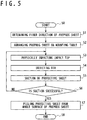
- Fig. 5 is a flowchart showing an example of each step of a method of peeling protective sheet from prepreg sheet according to an embodiment of the present invention.
- the movable arm 12 holds and moves the prepreg sheet 50 attached with the protective sheet 40 and places them on the mounting table 13 so that the edge section 55 or the corner section 56 of the prepreg sheet 50 and the protective sheet 40 overhangs from the edge section 131 of the mounting table 13 by a given length, as the impact tip 57 to be impacted by the peeling trigger section 14 (step S2).
- the movable arm 12 determines in advance, by the determination section 161, the fiber direction 54 of the prepreg sheet 50 (step S1), and arrange the prepreg sheet 50 by controlling the crossing angle 59 between the fiber direction 54 of the prepreg sheet 50 and the edge side direction 132 of the edge section 131 of the mounting table 13 to be included in a favorable range.
- the rotations shaft 142 rotates by a movement of the motor 141, the wing sections 143, 144 provided to the rotation shaft 142 directly contact with and physically impact the protective sheet 40 to partially peel the protective sheet 40 from the prepreg sheets 50 and then a state in which the protective sheet 40 is turned up can be obtained (step S3).
- the air nozzle 145 provided to the apparatus 1 for peeling the protective sheet 40 from the prepreg sheet 50 may efficiently induce the partial peeling of the protective sheet 40 from the prepreg sheet 50 by injecting the air 146 to the protective sheet 40 (step S4).
- step S5 After a given time has passed, the movable section 152 of the peeling section 15 is driven, the suction pad 151 is lowered by use of an air cylinder or the like and a suction of the protective sheet 40 in a partially peeled state is tried (step S5).
- the movable section 152 of the peeling section 15 is again driven and the suction pad 151 is raised.
- the movable arm 12 drives and moves the protective sheet 40 so that the protective sheet 40 can be peeled from the entire surface of the prepreg sheet 50 (step S7).
- step S6 the peeling trigger section 14 is driven again during a given time and the movable section 152 of the peeling section 15 is driven again (step S3). After that, the step of driving the peeling trigger section 14 and the step of driving the peeling section 15 will be repeated until the protective sheet 40 is peeled from the entire surface of the prepreg sheet 50.
Landscapes
- Engineering & Computer Science (AREA)
- Mechanical Engineering (AREA)
- Chemical & Material Sciences (AREA)
- Composite Materials (AREA)
- Reinforced Plastic Materials (AREA)
- Moulding By Coating Moulds (AREA)
- Folding Of Thin Sheet-Like Materials, Special Discharging Devices, And Others (AREA)
Abstract
Description
- The present embodiment is concerning a method of peeling protective sheet from prepreg sheet and an apparatus for peeling to be used therein.
- Body, main wings and the like of aircrafts are manufactured by use of prepreg laminate bodies configured by laminating a plurality of prepreg sheets which are punched thin plates of Carbon Fiber Reinforced Plastics (CFRP) or the like. In addition, each prepreg sheet is manufactured by impregnating a fiber sheet, in which a plurality of fibers is arranged in parallel, with a UV curable resin, thermosetting resin or the like in a semi-cured state which are not completely cured and have tackiness. Therefore, one surface or both surfaces of the prepreg sheet is/are attached with a protective sheet, because of the tackiness. Here, fibers which form one prepreg sheet are arranged aligned in a single direction, in a fiber direction in which the fibers extend.
- The prepreg laminate body is manufactured by removing the protective sheet from the prepreg sheet, spreading prepreg sheets in a first layer of the prepreg laminate body, then spreading prepreg sheets in a second layer similarly and laminating a plurality of layers of prepreg sheets. Here, it is favorable that fiber directions in two adjacently laminated prepreg sheets cross in a prepreg laminate body that requires a material strength. For example, in a given planar coordinate system, a prepreg sheet with a fiber direction oriented in 0 degree direction is laminated with another prepreg sheet with a fiber direction oriented in 45 degrees or 90 degrees thereon, and a plurality of prepreg sheets are laminated by crossing fiber directions.
- Conventionally, those techniques of laminating prepreg sheets required operations by human hands, because delicate skills are required, while recently, market needs increase in productivity improvement and cost reduction, and prepreg sheet laminating apparatuses, which efficiently laminate prepreg sheets, are in practical use.
- For example, the prepreg laminating apparatus disclosed in the patent literature 1 is provided with a first roller, a second roller and a means for peeling release paper in advance and is used to laminate a plurality of prepreg sheets, in which fiber sheets are impregnated with a resin, to form a prepreg laminate body. A protective sheet is attached on one surface of the prepreg sheet and the prepreg laminating apparatus has a function of peeling the protective sheet. The first roller is arranged in a front-rear direction of a body to be laminated and guides the prepreg sheet in a single direction. In addition, the second roller presses the prepreg sheet having passed the first roller from one surface thereof and guides the protective sheet in order to peel from the one surface of the prepreg sheet, so that the protective sheet is peeled.
-
- [Patent Literature 1]
JP 2011-177939A - [Patent Literature 2]
JP S63-288721A - However, the prepreg laminating apparatus disclosed in the patent literature 1 has a process of sandwiching the prepreg sheet attached with the protective sheet and tear the protective sheet off while pressing, in order to peel the protective sheet from the prepreg sheet. The prepreg sheet is vulnerable to excessive pressure because formed by impregnating with a resin in semi-cured state, and therefore the prepreg sheet may be damaged while tearing-off process. In addition, peeling effect is weak and limited in peeling technology using rollers and effective peeling technologies are required.
- By the above, the present invention aims to provide a method of peeling a protective sheet from a prepreg sheet more efficiently without damaging the prepreg sheet, and an apparatus for peeling to be used therein.
- According to a first aspect of the present invention, an apparatus for peeling a protective sheet from a prepreg sheet is provided with a mounting table, a movable arm, a peeling trigger section and a peeling section. Here, the movable arm holds a prepreg sheet attached with the protective sheet to move the prepreg sheet on the mounting table and arranges the prepreg sheet so that an edge section of both the prepreg sheet and the protective sheet overhangs the mounting table. The peeling trigger section impacts a part of the prepreg sheet and the protective sheet which overhangs the mounting table so that at least a part of the protective sheet is peeled from the prepreg sheet. The peeling section holds by suction the protective sheet and completely peels the protective sheet from the prepreg sheet.
- According to a second aspect of the present invention, a method of peeling a protective sheet from a prepreg sheet includes a step of determining a fiber direction of a prepreg sheet, a step of physically impacting a protective sheet attached to the prepreg sheet from a direction to bend fibers of the prepreg sheet, to partially peel the protective sheet from the prepreg sheet and a step of holding and moving the partially peeled protective sheet to peel the protective sheet from the entire surface of the prepreg sheet.
- According to the method of peeling a protective sheet from a prepreg sheet and the apparatus for peeling a protective sheet from a prepreg sheet in the present invention, a protective sheet can be peeled effectively, without damaging a prepreg sheet attached with the protective sheet.
-
-
Fig. 1A is a top view schematically showing an example of a shape of a prepreg sheet used in the present invention; -
Fig. 1B is a diagram showing a configuration example of a prepreg laminate body; -
Fig. 1C is a top view showing an example of positional relationship of a prepreg sheet, edge sections and corner sections; -
Fig. 2 is a diagram showing an example of an overall configuration of an apparatus for peeling protective sheet from prepreg sheet according to an embodiment of the present invention; -
Fig. 3 is a diagram showing an essential part of a movable arm according to an embodiment of the present invention; -
Fig. 4A is a perspective view showing an essential part of a peeling trigger section according to an embodiment of the present invention; -
Fig. 4B is a diagram showing an example of a gap according to the present embodiment; -
Fig. 4C is a diagram showing an example of an edge side direction according to the present embodiment; -
Fig. 4D is a diagram showing an example of a crossing angle according to the present embodiment; -
Fig. 4E is a diagram showing an essential part of a peeling section according to the present embodiment; -
Fig. 5 is a flowchart showing an example of each step of a method of peeling protective sheet from prepreg sheet according to an embodiment of the present invention. - An apparatus for peeling a protective sheet from a prepreg sheet according to an embodiment of the present invention will be described below, by use of drawings.
- A prepreg sheet to be processed by the apparatus for peeling protective sheet from prepreg sheet according to an embodiment of the present invention is formed by impregnating a fiber sheet, in which a plurality of fibers are arranged by aligning a fiber direction, with a Ultra Violet (UV) curable resin, a thermosetting resin or the like in a semi-cured state. Here, at least one of surfaces of the prepreg sheet has tackiness and therefore is attached with a protective sheet consisting of Polyethylene Terephthalate (PET), Polyester (PEs) or the like. In addition, a prepreg laminate body, which is a material for composite material, is formed by laminating a plurality of prepreg sheet layers. A first prepreg sheet layer is formed by removing protective sheet from each prepreg sheet and by arranging a plurality of prepreg sheets in parallel to spread on a flat surface.
-
Fig. 1A is a top view schematically showing an example of a shape of a prepreg sheet 50 used in the present invention. In the example ofFig. 1A , the first layer of the prepreg laminate body, in which afiber direction 54 of the prepreg sheet 50 is arranged in 45 degrees with respect to a given planar coordinate system, is formed by spreading prepreg sheets with a parallelogram shape (first pieces 51), a prepreg sheet of trapezoid shape (second piece 52) and a prepreg sheet of triangle shape (third piece 53). -
Fig. 1B is a diagram showing a configuration example of aprepreg laminate body 100. Theprepreg laminate body 100 is manufactured by forming aprepreg sheet 60 as a second layer of theprepreg laminate body 100, aprepreg sheet 70 as a third layer of the same and aprepreg sheet 80 as a fourth layer, similarly to the prepreg sheet 50 as a first layer of theprepreg laminate body 100, and by sequentially laminating thoseprepreg sheets - Here, in order to improve strength of the
prepreg laminate body 100, it is favorable that thefiber direction 54 of the prepreg sheet 50 of the first layer and afiber direction 64 of theprepreg sheet 60 of the second layer are different. For example, on a prepreg sheet with a fiber direction of 0 degree, another prepreg sheet with a fiber direction of 45 degrees or 90 degrees is laminated, and so on, a plurality of prepreg sheets are laminated so that respective fiber direction cross. Here, an outer peripheral part of the prepreg sheet 50 will be callededge section 55, and vertex part of theedge section 55 in particular will be calledcorner section 56.Fig. 1C is a top view showing an example of positional relationship of a prepreg sheet 50,edge sections 55 andcorner sections 56. -
Fig. 2 is a diagram showing an example of an overall configuration of an apparatus 1 for peeling protective sheet from prepreg sheet according to an embodiment of the present invention. As shown inFig. 1 , the apparatus 1 for peeling protective sheet from prepreg sheet is provided with amovable arm 12, which holds and moves a prepreg sheet attached with a protective sheet, a mounting table 13, on which the prepreg sheet attached with the protective sheet is placed, a peelingtrigger section 14, which physically impacts the prepreg sheet attached with the protective sheet and partially peels the protective sheet from the prepreg sheet to trigger peeling of the protective sheet, and apeeling section 15, which holds and moves the protective sheet partially peeled from the prepreg sheet to peel the protective sheet from the entire surface of the prepreg sheet. - The
movable arm 12 is provided with ahand section 121, which hold the prepreg sheet, amovable section 122, which moves the prepreg sheet held by thehand section 121 to the mounting table 13, and acontrol section 16. In the configuration example inFig. 2 , a same configuration is used as thehand section 121 and as thepeeling section 15. - The peeling
trigger section 14 is provided with amotor 141, arotation shaft 142 andwing section control section 16 is provided with adetermination section 161. -
Fig. 3 is a diagram showing an essential part of ahand section 121 of amovable arm 12 according to an embodiment of the present invention. For example, thehand section 121 is provided with asuction pad 123 and arotation section 124. Thesuction pad 123 makes a surface of thesuction pad 123 in a vacuum state, by use of a non-illustrated vacuum ejector, to enable a sheet-shaped target object in contact with thesuction pad 123 to be held by suction thereon. Themovable sections 122 inFig. 2 are connected to thehand section 121 to support thehand sections 121 and are able to freely move thehand section 121 in a vertical direction and in a horizontal direction. Therotation section 124 is able to rotate the held prepreg sheet 50 in 360 degrees in horizontal plane, by rotating thesuction pad 123. - Here, moves of the
movable arm 12 in horizontal direction, vertical direction and rotation direction are able to drive themovable sections 122 in accordance with thecontrol section 16 provided in themovable arm 12, and arrange the prepreg sheet 50 held by thehand section 121, by freely controlling a position and an angle with respect to the mounting table 13. In addition, thecontrol section 16 is further provided with adetermination section 161, which determines afiber direction 54 of fibers that the prepreg sheet 50 contains, and is able to freely control the position and the angle of the prepreg sheet 50 with respect to the mounting table 13, in accordance with the determination result of thefiber direction 54. - Here, the determination of the
fiber direction 54 may be performed, for example, by use of a Charge Coupled Device (CCD) camera and an image recognition processing device which are not illustrated. Here, the image recognition processing device may be a computer which is provided with a processing device, a memory device and various interfaces and executes given programs. Firstly, various prepreg sheets are formed in different shapes respectively to fiber directions thereof. Data showing relationship between shapes and fiber directions of the prepreg sheets may be stored in the memory device of the image recognition processing device. In the example ofFig. 1B , the prepreg sheet 50, of which thefiber direction 54 is in 45 degrees with respect to the planar coordinate system OXY, and theprepreg sheet 70, of which thefiber direction 74 is in -45 degrees with respect to the same coordinate system, both have a parallelogram shape. However, twoprepreg sheets 50 and 70, of which the fiber directions are different, cannot be overlapped to each other unless any one is turned over. Similarly, each part of theprepreg sheet 80, of which thefiber direction 84 is 0 degree with respect to the planar coordinate system OXY, and each part of theprepreg sheet 60, of which thefiber direction 64 is 90 degrees with respect to the same coordinate system, both have a rectangular shape and share a feature in which the longitudinal direction thereof is identical to the fiber direction thereof, while can be distinguished by sizes and aspect ratios thereof. As described above, it is favorable that the relationship between shapes of theprepreg sheets fiber directions - It should be noted that the
hand section 121 may be provided with a configuration, other than a suction member, to hold the prepreg sheet 50 by sandwiching for example, and in addition, may use further other member as long as such configuration can grip the sheet. In addition, thecontrol section 16 and thedetermination section 161 do not need to be provided integrated to themovable arm 12, and may be provided as a new mechanism having thecontrol section 16 and thedetermination section 161 separately. - The mounting table 13 has a flat plate shape able to horizontally support the prepreg sheet 50 at any position, and a prepreg sheet 50, which is held and moved by the
movable arm 12 and to which the protective sheet 40 is attached with, is placed thereon. - Here, the prepreg sheet 50 is placed on the mounting table 13 with the protective sheet 40 to be peeled as the top surface. In other words, by placing the prepreg sheet 50 with its surface to which the protective sheet is not attached with as the bottom surface, the position of the prepreg sheet 50 with respect to the mounting table 13 may be easily fixed, by the tackiness of the bottom surface of the prepreg sheet 50. In addition, the prepreg sheet 50 is arranged so that a part of the
edge section 55 or thecorner section 56 of the prepreg sheet 50 overhangs theedge section 131 of the mounting table 13. Here, the part of the prepreg sheet 50 overhanging theedge section 131 of the mounting table 13 is used as animpact tip 57 for the peelingtrigger section 14 to physically impact the prepreg sheet 50. In addition, the mounting table 13 may be provided with a holding device to hold the prepreg sheet 50, a mechanism to hold the prepreg sheet 50 by a vacuum suction or static electricity, or the like. - The peeling
trigger section 14 directly and physically impacts the protective sheet 40 in the part ofimpact tip 57, of the prepreg sheet 50 placed on the mounting table 13 in a state in which the protective sheet 40 is attached with on the top surface thereof, to cause a partial peeling between the protective sheet 40 and the prepreg sheet 50. -
Fig. 4A is a diagram showing an essential part of a peelingtrigger section 14 according to an embodiment of the present invention. The peelingtrigger section 14 inFig. 4A is provided with themotor 141 inFig. 2 , arotation shaft 142 which rotates by a power of themotor 141 and thefirst wing section 143 and thesecond wing section 144 provided to therotation shaft 142. Therotation shaft 142, to which a power of themotor 141 is transmitted, is arranged at a position in which thewing sections rotation shaft 142, can physically impact a part of theimpact tip 57 of the prepreg sheet 50 and the protective sheet 40, directly. Therotation shaft 142 may be integrated to a rotation shaft of themotor 141, or may be arotation shaft 142 which is transmitted with a power from the rotation shaft of themotor 141 to separately rotate. - Here, the inventors of the present invention have found out that, when partially peeling the protective sheet 40 from the prepreg sheet 50, an effect of partially peeling the protective sheet 40 is enhanced by arranging the
edge section 55 or thecorner section 56 of the prepreg sheet 50 and the protective sheet 40, with an overhanging from theedge section 131 of the mounting table 13 by a given length, as theimpact tip 57. In addition, it is favorable that the length of theimpact tip 57 is set between 20mm and 30mm to effectively peel the protective sheet 40. - In addition, as described above, fibers in one prepreg sheet 50 is arranged in one substantially same direction; however, the inventors of the present invention have found out that, when performing the peeling of the protective sheet 40 from the prepreg sheet 50, the effect of peeling the protective sheet is enhanced by satisfying following three conditions.
- That is, as a first condition, each of the
edge section 131 of the mounting table 13, which theimpact tip 57 overhangs, and edge sections of thewing section wing sections edge section 131 of the mounting table 13 are in parallel at the moment thewing sections impact tip 57. - As a second condition, a
gap 58 from the edge sections of thewing sections edge section 131 of the mounting table 13 is short enough at the moment thewing sections impact tip 57.Fig. 4B is a diagram showing an example of agap 58 according to the present embodiment. Concerning the second condition, the length of thegap 58 is favorably longer than 1mm and shorter than 2.5mm. However, it is favorable that the favorable range of the length of thegap 58 is appropriately adjustable in accordance with a sum of thickness of each of the prepreg sheet 50 and the protective sheet 40, acrossing angle 59 between thefiber direction 54 of the prepreg sheet 50 and theedge side direction 132 of theedge section 131 of the mounting table 13, a number and materials of thewing sections Fig. 4C is a diagram showing an example of anedge side direction 132 according to the present embodiment.Fig. 4D is a diagram showing an example of acrossing angle 59 according to the present embodiment. - As a third condition, the crossing
angle 59 between theedge side direction 132 of theedge section 131 of the mounting table 13 and thefiber direction 54 of the prepreg sheet 50 is large enough. This third condition means in other words that the prepreg sheet 50 is arranged with respect to the mounting table 13 so that the physical impact from thewing sections trigger section 14 is added in a direction to bend fibers of the prepreg sheet 50. Concerning this third condition, the apparatus 1 for peeling a protective sheet 40 from a prepreg sheet 50 according to an embodiment of the present invention firstly determines thefiber direction 54 of the prepreg sheet 50 by thedetermination section 161. Next, thecontrol section 16 controls the direction of thehand section 121 of themovable arm 12 by appropriately rotating themovable sections 122 and therotation section 124, so that the crossingangle 59 between thefiber direction 54 of the prepreg sheet 50 and theedge side direction 132 of theedge section 131 of the mounting table 13 is included in a favorable range. In this way, the apparatus 1 for peeling the protective sheet 40 from the prepreg sheet 50 according to the present embodiment can place the prepreg sheet 50 attached with the protective sheet 40 on the mounting table 13 with a favorable position and a favorable angle both relative to theedge section 131. - Here, it is favorable to place the prepreg sheet 50 on the mounting table 13 so that the crossing
angle 59 between thefiber direction 54 of the prepreg sheet 50 and theedge side direction 132 is included in a range between 10 degrees and 170 degrees. This crossingangle 59 is preferably included in a range between 30 degrees and 150 degrees, is further preferably included in a range between 60 degrees and 120 degrees, and ideally equals to 90 degrees. - In addition, each of the
wing sections rotation shaft 142. In addition, thewing sections rotation shaft 142 may be single or plural. For example, the shape of each of thewing sections wing sections impact tip 57 of the prepreg sheet 50 and the protective sheet 40 overhanging the mounting table. - The peeling
section 15 completely peels the protective sheet 40 from an entire surface of the prepreg sheet 50 by holding and moving a part of the protective sheet 40 partially peeled from the prepreg sheet 50. Here, as shown inFig. 2 , the apparatus 1 for peeling the protective sheet 40 from the prepreg sheet 50 according to an embodiment of the present invention may provide thehand section 121 of themovable arm 12 with a function similar to the one of thepeeling section 15, that is, the peeling section may be integrated to themovable arm 12. -
Fig. 4E is a diagram showing an essential part of apeeling section 15 according to an embodiment of the present invention. The peelingsection 15 inFig. 4E is provided with asuction pad 151, which holds the protective sheet 40 by vacuum suction, and amovable section 152 including an air cylinder which supports thesuction pad 151 with a vertical movability in up and down directions. Thesuction pad 151 holds by suction the part of theimpact tip 57, which overhangs the mounting table 13, of the protective sheet 40, and which is peeled from the prepreg sheet 50 by the peelingtrigger section 14, and then remain in this state and rises by movement of themovable section 152 to peel the protective sheet 40 from the entire surface of the prepreg sheet 50. - The peeling
section 15 may be provided to themovable arm 12 via therotation section 124, or, another movable arm with thesuction pad 151 may be provided to be used as thepeeling section 15. Here, the peelingsection 15 is not limited to a peeling method by use of a suction member. The peelingsection 15 may be a configuration able to hold the protective sheet 40 by sandwiching, for example, and any other member may be used as thepeeling section 15 as long as it can hold the protective sheet 40. - In addition, the apparatus 1 for peeling the protective sheet 40 from the prepreg sheet 50 may be provided with an
air nozzle 145 which injectsair 146 to the prepreg sheet 50 attached with the protective sheet 40. In a step of operating the peelingtrigger section 14, by injectingair 146 to the edge section of theimpact tip 57 overhanging the mounting table 13, a peeling efficiency of the peelingtrigger section 14 can be improved. In addition, to effectively peel the protective sheet 40, it is favorable to arrange anair nozzle 145 in a position from below of which theair 146 can be injected to the edge section of theimpact tip 57 overhanging the mounting table 13. - Next, an operation of the apparatus 1 for peeling the protective sheet 40 from the prepreg sheet 50 according to the present embodiment, that is, a method of peeling the protective sheet 40 from the prepreg sheet 50 according to the present embodiment, will be described.
Fig. 5 is a flowchart showing an example of each step of a method of peeling protective sheet from prepreg sheet according to an embodiment of the present invention. Firstly, themovable arm 12 holds and moves the prepreg sheet 50 attached with the protective sheet 40 and places them on the mounting table 13 so that theedge section 55 or thecorner section 56 of the prepreg sheet 50 and the protective sheet 40 overhangs from theedge section 131 of the mounting table 13 by a given length, as theimpact tip 57 to be impacted by the peeling trigger section 14 (step S2). - Here, the
movable arm 12 determines in advance, by thedetermination section 161, thefiber direction 54 of the prepreg sheet 50 (step S1), and arrange the prepreg sheet 50 by controlling thecrossing angle 59 between thefiber direction 54 of the prepreg sheet 50 and theedge side direction 132 of theedge section 131 of the mounting table 13 to be included in a favorable range. - Next, in the peeling
trigger section 14, therotations shaft 142 rotates by a movement of themotor 141, thewing sections rotation shaft 142 directly contact with and physically impact the protective sheet 40 to partially peel the protective sheet 40 from the prepreg sheets 50 and then a state in which the protective sheet 40 is turned up can be obtained (step S3). Here, theair nozzle 145 provided to the apparatus 1 for peeling the protective sheet 40 from the prepreg sheet 50 may efficiently induce the partial peeling of the protective sheet 40 from the prepreg sheet 50 by injecting theair 146 to the protective sheet 40 (step S4). - Next, after a given time has passed, the
movable section 152 of thepeeling section 15 is driven, thesuction pad 151 is lowered by use of an air cylinder or the like and a suction of the protective sheet 40 in a partially peeled state is tried (step S5). - Next, after a given time has passed, the
movable section 152 of thepeeling section 15 is again driven and thesuction pad 151 is raised. Here, in a case in which thepeeling section 15 is holding the protective sheet 40 by suction ("YES" in step S6), themovable arm 12 drives and moves the protective sheet 40 so that the protective sheet 40 can be peeled from the entire surface of the prepreg sheet 50 (step S7). - On the other hand, in a case in which the
peeling section 15 is not holding the protective sheet 40 by suction or the holding by suction is not enough ("NO" in step S6), the peelingtrigger section 14 is driven again during a given time and themovable section 152 of thepeeling section 15 is driven again (step S3). After that, the step of driving the peelingtrigger section 14 and the step of driving thepeeling section 15 will be repeated until the protective sheet 40 is peeled from the entire surface of the prepreg sheet 50. - Embodiments of the present invention have been described above in detail by use of drawings while each configuration, combinations thereof and the like in each embodiment are examples and are not intended to limit the scope of the invention, unless sizes, materials, shapes, relative arrangements thereof and the like of component parts shown in the embodiments are especially and specifically described. In addition, additions, omissions, substitutions and other modifications of configuration can be performed without departing from the spirit of the present invention.
- The present application is based on the Japanese Patent Application (
JP 2017-046076) filed on March 10, 2017
Claims (5)
- An apparatus for peeling a protective sheet from a prepreg sheet, comprising:a mounting table;a movable arm configured to hold a prepreg sheet attached with a protective sheet to move the prepreg sheet on the mounting table and arrange the prepreg sheet so that an edge section of both the prepreg sheet and the protective sheet overhangs the mounting table;a peeling trigger section configured to impact a part of the prepreg sheet and the protective sheet which overhangs the mounting table so that at least a part of the protective sheet is peeled from the prepreg sheet; anda peeling section configured to hold by suction the protective sheet and completely peel the protective sheet from the prepreg sheet.
- The apparatus for peeling a protective sheet from a prepreg sheet according to claim 1, further comprising:a determination section configured to determine a fiber direction of the prepreg sheet; anda control section configured to control an angle between a first direction, which is the fiber direction of the prepreg sheet, and a second direction, which is a direction of an edge section of the mounting table that the prepreg sheet and the protective sheet overhang, so that the angle is greater than 30 degrees and smaller than 150 degrees.
- The apparatus for peeling a protective sheet from a prepreg sheet according to claim 2,
wherein the peeling trigger section comprises:a motor;a rotation shaft configured to rotate by a power of the motor; anda wing section provided along the rotation shaft. - The apparatus for peeling a protective sheet from a prepreg sheet according to claim 3, further comprising:
an air nozzle configured to inject air to the protective sheet which is partially peeled to induce a further peeling of the protective sheet. - A method of peeling a protective sheet from a prepreg sheet, comprising:a step of determining a fiber direction of a prepreg sheet;a step of physically impacting a protective sheet attached to the prepreg sheet from a direction to bend fibers of the prepreg sheet, to partially peel the protective sheet from the prepreg sheet; anda step of holding and moving the protective sheet partially peeled to peel the protective sheet from an entire surface of the prepreg sheet.
Applications Claiming Priority (2)
| Application Number | Priority Date | Filing Date | Title |
|---|---|---|---|
| JP2017046076A JP6745745B2 (en) | 2017-03-10 | 2017-03-10 | Peeling method for protective sheet for prepreg sheet, and peeling apparatus for protective sheet for prepreg sheet |
| PCT/JP2018/001360 WO2018163608A1 (en) | 2017-03-10 | 2018-01-18 | Method for peeling protective sheet for prepreg sheet, and apparatus for peeling protective sheet for prepreg sheet |
Publications (2)
| Publication Number | Publication Date |
|---|---|
| EP3569535A1 true EP3569535A1 (en) | 2019-11-20 |
| EP3569535A4 EP3569535A4 (en) | 2020-03-11 |
Family
ID=63447403
Family Applications (1)
| Application Number | Title | Priority Date | Filing Date |
|---|---|---|---|
| EP18763459.7A Withdrawn EP3569535A4 (en) | 2017-03-10 | 2018-01-18 | Method for peeling protective sheet for prepreg sheet, and apparatus for peeling protective sheet for prepreg sheet |
Country Status (4)
| Country | Link |
|---|---|
| US (1) | US11331898B2 (en) |
| EP (1) | EP3569535A4 (en) |
| JP (1) | JP6745745B2 (en) |
| WO (1) | WO2018163608A1 (en) |
Cited By (1)
| Publication number | Priority date | Publication date | Assignee | Title |
|---|---|---|---|---|
| EP4360856A1 (en) * | 2022-10-27 | 2024-05-01 | The Boeing Company | Separation of film layer from composite prepreg |
Families Citing this family (4)
| Publication number | Priority date | Publication date | Assignee | Title |
|---|---|---|---|---|
| CN116512734B (en) * | 2023-06-29 | 2023-08-25 | 山东莱蔚特复合材料有限责任公司 | A carbon fiber prepreg post-processing and film removal equipment |
| US12589585B2 (en) | 2023-08-08 | 2026-03-31 | Accudyne Systems, Inc. | Prepreg composite material ply and backing separation systems and methods |
| US12623449B2 (en) * | 2023-10-19 | 2026-05-12 | The Boeing Company | Composite backing layer peel starter |
| US12623368B2 (en) * | 2023-10-23 | 2026-05-12 | General Electric Company | Systems and methods of automatic film removal |
Family Cites Families (14)
| Publication number | Priority date | Publication date | Assignee | Title |
|---|---|---|---|---|
| JPS63288721A (en) | 1987-05-20 | 1988-11-25 | Ishikawajima Harima Heavy Ind Co Ltd | Peeling device of release paper from prepreg |
| KR100429326B1 (en) | 1994-12-21 | 2004-07-14 | 킹 짐(주) | Peeling method of adhesive sheet and its device |
| JP3138417B2 (en) * | 1995-11-29 | 2001-02-26 | セイコーエプソン株式会社 | Adhesive tape peeling device and tape printing device |
| JP3336203B2 (en) * | 1995-09-25 | 2002-10-21 | 株式会社リコー | Sheet processing apparatus and sheet processing method |
| JP4121257B2 (en) * | 2001-07-11 | 2008-07-23 | 富士フイルム株式会社 | Sheet body handling device |
| US6907711B2 (en) | 2001-07-09 | 2005-06-21 | Fuji Photo Film Co., Ltd. | Sheet package producing system, sheet handling device, and fillet folding device |
| JP4107382B2 (en) * | 2002-11-22 | 2008-06-25 | 凸版印刷株式会社 | Conductive thin film conductivity measuring device |
| US7823619B2 (en) | 2004-07-02 | 2010-11-02 | Sharp Kabushiki Kaisha | Film stripping method and apparatus |
| JP4518916B2 (en) * | 2004-11-08 | 2010-08-04 | 東レ株式会社 | Manufacturing method of laminate |
| JP2008037574A (en) * | 2006-08-07 | 2008-02-21 | Matsushita Electric Ind Co Ltd | Lamination sheet peeling method and peeling apparatus used therefor |
| JP5439225B2 (en) | 2010-02-26 | 2014-03-12 | 三菱重工業株式会社 | Prepreg laminating head and prepreg automatic laminating apparatus provided with the same |
| GB2490152A (en) | 2011-04-20 | 2012-10-24 | Umeco Structural Materials Derby Ltd | Automated Prepreg Processing, removal of an external film |
| US9358770B2 (en) | 2014-04-30 | 2016-06-07 | The Boeing Company | System and method for automated initial separation of composite ply backing |
| JP2017046076A (en) | 2015-08-24 | 2017-03-02 | シャープ株式会社 | COMMUNICATION DEVICE, COMMUNICATION SYSTEM, AND COMMUNICATION DEVICE CONTROL METHOD |
-
2017
- 2017-03-10 JP JP2017046076A patent/JP6745745B2/en active Active
-
2018
- 2018-01-18 EP EP18763459.7A patent/EP3569535A4/en not_active Withdrawn
- 2018-01-18 WO PCT/JP2018/001360 patent/WO2018163608A1/en not_active Ceased
- 2018-01-18 US US16/492,194 patent/US11331898B2/en active Active
Cited By (2)
| Publication number | Priority date | Publication date | Assignee | Title |
|---|---|---|---|---|
| EP4360856A1 (en) * | 2022-10-27 | 2024-05-01 | The Boeing Company | Separation of film layer from composite prepreg |
| US12330288B2 (en) | 2022-10-27 | 2025-06-17 | The Boeing Company | Separation of film layer from composite prepreg |
Also Published As
| Publication number | Publication date |
|---|---|
| JP6745745B2 (en) | 2020-08-26 |
| WO2018163608A1 (en) | 2018-09-13 |
| JP2018150098A (en) | 2018-09-27 |
| EP3569535A4 (en) | 2020-03-11 |
| US11331898B2 (en) | 2022-05-17 |
| US20200391497A1 (en) | 2020-12-17 |
Similar Documents
| Publication | Publication Date | Title |
|---|---|---|
| US11331898B2 (en) | Method of peeling protective sheet for prepreg sheet and apparatus for peeling protective sheet from prepreg sheet | |
| US11999149B2 (en) | Automated system and method for forming a laminated structure | |
| US8562778B2 (en) | Tape adhering apparatus and tape adhering method | |
| EP3904047B1 (en) | Method and device for molding laminate | |
| JP2012004290A (en) | Sheet peeling device and sheet peeling method | |
| CN212380410U (en) | Mechanical stripping off device of flexible substrate | |
| CN106061696B (en) | Prepreg Cutting and Laminating Device | |
| KR20180007665A (en) | Long body connecting apparatus and connection method | |
| KR101123268B1 (en) | Large-area film wrinkle removal device that is attached to a glass | |
| CN101308276A (en) | Spacer removal device and method for removing same | |
| KR101685316B1 (en) | Molding assembly, molding assembly manufacturing device, and method for manufacturing molding assembly | |
| JP2009029014A (en) | Substrate assembling device and assembling method | |
| JP5973303B2 (en) | Laminated body | |
| US12623368B2 (en) | Systems and methods of automatic film removal | |
| JP5981822B2 (en) | Sheet sticking device and sheet sticking method | |
| KR101186122B1 (en) | Apparatus for peeling protect film | |
| JP5587717B2 (en) | Sheet sticking device and sticking method | |
| JP2586695Y2 (en) | Edge peeling device | |
| CN103738045A (en) | Film tearing device | |
| TWM511180U (en) | Film peeling device | |
| JP2020189742A (en) | Adhesive sheet peeling system | |
| JP2023050392A (en) | Sheet sticking device and sheet sticking method | |
| JPS62181489A (en) | Thin film peeling device | |
| JP2014201376A (en) | Peeling method of sticking material | |
| JP2015089831A (en) | Sheet positioning method |
Legal Events
| Date | Code | Title | Description |
|---|---|---|---|
| STAA | Information on the status of an ep patent application or granted ep patent |
Free format text: STATUS: THE INTERNATIONAL PUBLICATION HAS BEEN MADE |
|
| PUAI | Public reference made under article 153(3) epc to a published international application that has entered the european phase |
Free format text: ORIGINAL CODE: 0009012 |
|
| STAA | Information on the status of an ep patent application or granted ep patent |
Free format text: STATUS: REQUEST FOR EXAMINATION WAS MADE |
|
| 17P | Request for examination filed |
Effective date: 20190717 |
|
| AK | Designated contracting states |
Kind code of ref document: A1 Designated state(s): AL AT BE BG CH CY CZ DE DK EE ES FI FR GB GR HR HU IE IS IT LI LT LU LV MC MK MT NL NO PL PT RO RS SE SI SK SM TR |
|
| AX | Request for extension of the european patent |
Extension state: BA ME |
|
| A4 | Supplementary search report drawn up and despatched |
Effective date: 20200212 |
|
| RIC1 | Information provided on ipc code assigned before grant |
Ipc: B29C 70/54 20060101ALI20200206BHEP Ipc: B65H 41/00 20060101AFI20200206BHEP |
|
| DAV | Request for validation of the european patent (deleted) | ||
| DAX | Request for extension of the european patent (deleted) | ||
| STAA | Information on the status of an ep patent application or granted ep patent |
Free format text: STATUS: THE APPLICATION HAS BEEN WITHDRAWN |
|
| 18W | Application withdrawn |
Effective date: 20210701 |