EP3569523B1 - Robot for carrying container - Google Patents
Robot for carrying container Download PDFInfo
- Publication number
- EP3569523B1 EP3569523B1 EP17891876.9A EP17891876A EP3569523B1 EP 3569523 B1 EP3569523 B1 EP 3569523B1 EP 17891876 A EP17891876 A EP 17891876A EP 3569523 B1 EP3569523 B1 EP 3569523B1
- Authority
- EP
- European Patent Office
- Prior art keywords
- container
- robot
- carrying
- sensor
- unit
- Prior art date
- Legal status (The legal status is an assumption and is not a legal conclusion. Google has not performed a legal analysis and makes no representation as to the accuracy of the status listed.)
- Active
Links
Images
Classifications
-
- B—PERFORMING OPERATIONS; TRANSPORTING
- B66—HOISTING; LIFTING; HAULING
- B66F—HOISTING, LIFTING, HAULING OR PUSHING, NOT OTHERWISE PROVIDED FOR, e.g. DEVICES WHICH APPLY A LIFTING OR PUSHING FORCE DIRECTLY TO THE SURFACE OF A LOAD
- B66F9/00—Devices for lifting or lowering bulky or heavy goods for loading or unloading purposes
- B66F9/06—Devices for lifting or lowering bulky or heavy goods for loading or unloading purposes movable, with their loads, on wheels or the like, e.g. fork-lift trucks
- B66F9/063—Automatically guided
-
- B—PERFORMING OPERATIONS; TRANSPORTING
- B25—HAND TOOLS; PORTABLE POWER-DRIVEN TOOLS; MANIPULATORS
- B25J—MANIPULATORS; CHAMBERS PROVIDED WITH MANIPULATION DEVICES
- B25J5/00—Manipulators mounted on wheels or on carriages
- B25J5/007—Manipulators mounted on wheels or on carriages mounted on wheels
-
- B—PERFORMING OPERATIONS; TRANSPORTING
- B25—HAND TOOLS; PORTABLE POWER-DRIVEN TOOLS; MANIPULATORS
- B25J—MANIPULATORS; CHAMBERS PROVIDED WITH MANIPULATION DEVICES
- B25J19/00—Accessories fitted to manipulators, e.g. for monitoring, for viewing; Safety devices combined with or specially adapted for use in connection with manipulators
- B25J19/02—Sensing devices
-
- B—PERFORMING OPERATIONS; TRANSPORTING
- B25—HAND TOOLS; PORTABLE POWER-DRIVEN TOOLS; MANIPULATORS
- B25J—MANIPULATORS; CHAMBERS PROVIDED WITH MANIPULATION DEVICES
- B25J9/00—Program-controlled manipulators
- B25J9/16—Program controls
- B25J9/1615—Program controls characterised by special kind of manipulator, e.g. planar, scara, gantry, cantilever, space, closed chain, passive/active joints and tendon driven manipulators
- B25J9/162—Mobile manipulator, movable base with manipulator arm mounted on it
-
- B—PERFORMING OPERATIONS; TRANSPORTING
- B25—HAND TOOLS; PORTABLE POWER-DRIVEN TOOLS; MANIPULATORS
- B25J—MANIPULATORS; CHAMBERS PROVIDED WITH MANIPULATION DEVICES
- B25J9/00—Program-controlled manipulators
- B25J9/16—Program controls
- B25J9/1694—Program controls characterised by use of sensors other than normal servo-feedback from position, speed or acceleration sensors, perception control, multi-sensor controlled systems, sensor fusion
- B25J9/1697—Vision controlled systems
-
- B—PERFORMING OPERATIONS; TRANSPORTING
- B65—CONVEYING; PACKING; STORING; HANDLING THIN OR FILAMENTARY MATERIAL
- B65G—TRANSPORT OR STORAGE DEVICES, e.g. CONVEYORS FOR LOADING OR TIPPING, SHOP CONVEYOR SYSTEMS OR PNEUMATIC TUBE CONVEYORS
- B65G1/00—Storing articles, individually or in orderly arrangement, in warehouses or magazines
- B65G1/02—Storage devices
- B65G1/04—Storage devices mechanical
- B65G1/0407—Storage devices mechanical using stacker cranes
- B65G1/0435—Storage devices mechanical using stacker cranes with pulling or pushing means on either stacking crane or stacking area
-
- B—PERFORMING OPERATIONS; TRANSPORTING
- B65—CONVEYING; PACKING; STORING; HANDLING THIN OR FILAMENTARY MATERIAL
- B65G—TRANSPORT OR STORAGE DEVICES, e.g. CONVEYORS FOR LOADING OR TIPPING, SHOP CONVEYOR SYSTEMS OR PNEUMATIC TUBE CONVEYORS
- B65G1/00—Storing articles, individually or in orderly arrangement, in warehouses or magazines
- B65G1/02—Storage devices
- B65G1/04—Storage devices mechanical
- B65G1/0492—Storage devices mechanical with cars adapted to travel in storage aisles
-
- B—PERFORMING OPERATIONS; TRANSPORTING
- B65—CONVEYING; PACKING; STORING; HANDLING THIN OR FILAMENTARY MATERIAL
- B65G—TRANSPORT OR STORAGE DEVICES, e.g. CONVEYORS FOR LOADING OR TIPPING, SHOP CONVEYOR SYSTEMS OR PNEUMATIC TUBE CONVEYORS
- B65G1/00—Storing articles, individually or in orderly arrangement, in warehouses or magazines
- B65G1/02—Storage devices
- B65G1/04—Storage devices mechanical
- B65G1/137—Storage devices mechanical with arrangements or automatic control means for selecting which articles are to be removed
- B65G1/1371—Storage devices mechanical with arrangements or automatic control means for selecting which articles are to be removed with data records
-
- B—PERFORMING OPERATIONS; TRANSPORTING
- B66—HOISTING; LIFTING; HAULING
- B66F—HOISTING, LIFTING, HAULING OR PUSHING, NOT OTHERWISE PROVIDED FOR, e.g. DEVICES WHICH APPLY A LIFTING OR PUSHING FORCE DIRECTLY TO THE SURFACE OF A LOAD
- B66F9/00—Devices for lifting or lowering bulky or heavy goods for loading or unloading purposes
- B66F9/06—Devices for lifting or lowering bulky or heavy goods for loading or unloading purposes movable, with their loads, on wheels or the like, e.g. fork-lift trucks
- B66F9/07—Floor-to-roof stacking devices, e.g. "stacker cranes", "retrievers"
Definitions
- the present application relates to the field of logistics and warehousing, and in particular to a robot for carrying a container.
- a carrying robot is a kind of equipment used in the field of automatic material carrying, which has many advantages such as high degree of automation, flexible application, safety and reliability, high efficiency and convenient maintenance. Therefore, the carrying robot is widely used in logistics and transportation occasions such as automotive manufacturing industry, food industry, tobacco industry, construction machinery industry, and the carrying robot has also made achievements in various public service places such as airports, hospitals and office buildings. These advantages also make the carrying robot become the key equipment in a modern logistics system and become one of the important members of the "machine substituting labor" program.
- WO2016151504A1 discloses a robot drive unit (RDU), including an arm positioner that is mounted on a chassis of the RDU and that adjusts position of an arm unit in a vertical plane.
- the arm unit includes at least one arm to hold a product and an arm holder to hold the at least one arm.
- the arm positioner enables the arm unit to be moved along arm supporting structure.
- the arm unit includes an arm that further includes a base arm and an extendable arm, which is housed in the base arm.
- the extendable arm can be extended and retracted, which enables retrieving and storing the products. When extended, the extendable arm extends beyond the chassis of the RDU.
- the extendable arm can include holders.
- the technical issue to be addressed by the present application is how to improve the carrying efficiency of a carrying robot. Since it is a container to be carried and the volume and weight of the container are much smaller than that of a shelf, multiple containers can be carried at a time. A single container stores at least one kind of goods, so a variety of goods can be carried at a time.
- a robot for carrying a container which includes a drive unit, a container storage unit and a container transport unit, where the drive unit carries the container storage unit and the container transport unit to jointly move.
- the container storage unit includes one or more container storage spaces, and the container transport unit is arranged at one side of the container storage unit and is configured to transport the container between the container storage space and the shelf.
- the container storage unit includes support rails, pallets and reinforcing ribs, and the support rails, the pallets and the reinforcing ribs are connected with each other to form one or more container storage spaces.
- the container transport unit includes a lifting device, a rotating device and a telescopic fork tooth, one end of the lifting device is connected with the support rails and is slidable up and down along a vertical direction of the support rails, and another end of the lifting device is connected with the telescopic fork tooth through the rotating device, the telescopic fork tooth is configured to extend and retract along a telescopic direction, the rotating device drives the telescopic fork tooth to rotate, such that a telescopic direction of the telescopic fork tooth rotates.
- the drive unit includes a chassis frame and drive wheels configured to drive the robot to move or stop.
- the motion includes advance, reverse, turn and in-situ rotation.
- the pallets are configured to separate the storage spaces.
- the container transport unit includes a lifting device, a rotating device and a telescopic device, where one end of the lifting device is connected with the support rails and can slide up and down along a vertical direction of the support rails, and the other end of the lifting device is connected with the telescopic device through the rotating device.
- the robot for carrying a container further includes the container, the container storage spaces and the container have machine-readable codes, and the container transport unit further includes a positioning sensor and a pose sensor.
- the machine-readable code is a barcode or a two-dimensional barcode or a character string or an RFID.
- the positioning sensor is configured to detect a position of the container, and the positioning sensor is a vision sensor or a radio frequency sensor.
- the pose sensor is configured to detect a positional posture of the container on the container transport unit, and the pose sensor is a vision sensor or a radio frequency sensor.
- the pallet is a plate with an integral surface or the pallet is hollowed or partitioned.
- the process of the robot for carrying a container according to the present application carrying the container to the container storage unit is as follows, the carrying robot moves the container transport unit to a specified position through the lifting device, and rotates the telescopic fork tooth to a specified angle through the rotating device, then extends the telescopic fork tooth to a position below the container to be transported, then lifts the container through the lifting device, then retracts the container through the telescopic fork tooth, then rotates the telescopic fork tooth and the container to another specified angle through the rotating device, then moves the container to a position above the pallet through the telescopic fork tooth, then lowers the container through the lifting device to place the container on the pallet, and finally retracts the telescopic fork tooth. Therefore, the robot for carrying a container according to present application can transport a variety of goods at a time, and has high working efficiency and low energy consumption.
- the components When some components are described as 'on another component', the components may be placed directly on another component, or there may be an intermediate component, the components are placed on the intermediate component, and the intermediate component is placed on another component.
- the components When some components are described as 'mounted to' or 'connected to' another component, the components may be directly 'mounted to' or 'connected to' the other component, or there may be an intermediate component, and the components are 'mounted to' or 'connected to' another component through the intermediate component.
- a robot for carrying a container includes a drive unit 1, a container storage unit 2 and a container transport unit 3.
- the drive unit 1 includes a chassis frame 11 and drive wheels 12, where two drive wheels 12 are provided and symmetrically mounted on two sides of the chassis frame 11. By the rotation of the drive wheels 12, the advance, reverse, turn and in-situ rotation of the robot can be realized.
- the container storage unit 2 includes support rails 21, pallets 22 and reinforcing ribs 23.
- the support rails 21 are located above the drive unit 1.
- the support rails 21 are connected to each other by the pallets 22 and the reinforcing ribs 23, and the pallets 22 are configured to stack the containers.
- the container storage unit 2 can store multiple containers.
- Each of the pallets 22 is separated in the middle.
- the container transport unit 3 includes a frame 31, a lifting device 32, a telescopic fork tooth 33 and a rotating device 34.
- One end of the lifting device 31 is connected with the support rails 21 and can slide up and down along a vertical direction of the support rails 21, and another end is connected with the telescopic fork tooth 33 through the rotating device 34.
- the telescopic fork tooth 33 can rotate along the z-axis through the rotating device 34.
- the telescopic fork tooth 33 extends or retracts along the x direction. If the rotating device 34 drives the telescopic fork tooth 33 to rotate, a telescopic direction of the telescopic fork tooth 33 also rotates.
- the container transport unit 3 further includes a pose sensor 35 configured to identify a posture of the container above the telescopic fork tooth 33, and a positioning sensor 36 configured to detect a position of the container.
- the pose sensor 35 may be a vision sensor or other sensor that can obtain pose information.
- the positioning sensor 36 may be a vision sensor or other sensor that can obtain pose information.
- the process of the robot for carrying a container carrying the container 4 to the container storage unit 2 is as follows, the robot moves the container transport unit 3 to a specified position through the lifting device 32, and rotates the telescopic fork tooth 33 to a specified angle through the rotating device 34, then extends the telescopic fork tooth 33 to a position below the container 4 to be transported, then lifts the container 4 through the lifting device 32, then retracts the container 4 through the telescopic fork tooth 33, then rotates the telescopic fork tooth 33 and the container 4 to another specified angle through the rotating device 34, then moves the container 4 to a position above the pallet 22 through the telescopic fork tooth 33, then lowers the container 4 through the lifting device 32 to place the container on the pallet 22, and finally retracts the telescopic fork tooth 33.
- a robot for carrying a container includes a drive unit 1, a container storage unit 2 and a container transport unit 3.
- the drive unit 1 includes a chassis frame 11 and drive wheels 12, where two drive wheels 12 are provided and symmetrically mounted on both sides of the chassis frame 11. By the rotation of the drive wheels 12, the advance, reverse, turn and in-situ rotation of the robot can be realized.
- the container storage unit 2 includes support rails 21, pallets 22 and reinforcing ribs 23.
- the support rails 21 are located above the drive unit 1.
- the support rails 21 are connected to each other by the pallets 22 and the reinforcing ribs 23, and the pallets 22 are configured to stack the containers.
- the container storage unit 2 can store multiple containers.
- Each of the pallets 22 is a flat plate connected with the support rails 21 on both sides.
- the container transport unit 3 includes a frame 31, a lifting device 32, a telescopic fork tooth 33 and a rotating device 34.
- One end of the lifting device 31 is connected with the support rails 21 and can slide up and down along a vertical direction of the support rails 21, and the other end is connected with the telescopic fork tooth 33 through the rotating device 34.
- the telescopic fork tooth 33 can rotate along the z-axis through the rotating device 34.
- the telescopic fork tooth 33 can extend or retract along the x direction. If the rotating device 34 drives the telescopic fork tooth 33 to rotate, a telescopic direction of the telescopic fork tooth 33 also rotates.
- the container transport unit 3 further includes a pose sensor 35 configured to identify a posture of the container above the telescopic fork tooth 33, and a positioning sensor 36 configured to detect a position of the container.
- the pose sensor 35 may be a vision sensor or other sensor that can obtain pose information, such as a radio frequency sensor.
- the positioning sensor 36 may be a vision sensor or other sensor that can obtain pose information, such a radio frequency sensor.
- the process of the robot for carrying a container carrying the container 4 to the container storage unit 2 is as follows, the robot moves the container transport unit 3 to a specified position through the lifting device 32, and rotates the telescopic fork tooth 33 to a specified angle through the rotating device 34, then extends the telescopic fork tooth 33 to a position below the container 4 to be transported, then lifts the container 4 through the lifting device 32, then retracts the container 4 through the telescopic fork tooth 33, then rotates the telescopic fork tooth 33 and the container 4 to another specified angle through the rotating device 34, then moves the container 4 to a position above the pallet 22 through the telescopic fork tooth 33, then lowers the container 4 through the lifting device 32 to place the container on the pallet 22, and finally retracts the telescopic fork tooth 33.
Landscapes
- Engineering & Computer Science (AREA)
- Mechanical Engineering (AREA)
- Robotics (AREA)
- Structural Engineering (AREA)
- Transportation (AREA)
- Life Sciences & Earth Sciences (AREA)
- Civil Engineering (AREA)
- Geology (AREA)
- Health & Medical Sciences (AREA)
- General Health & Medical Sciences (AREA)
- Orthopedic Medicine & Surgery (AREA)
- Warehouses Or Storage Devices (AREA)
- Forklifts And Lifting Vehicles (AREA)
- Manipulator (AREA)
Description
- The present application relates to the field of logistics and warehousing, and in particular to a robot for carrying a container.
- A carrying robot is a kind of equipment used in the field of automatic material carrying, which has many advantages such as high degree of automation, flexible application, safety and reliability, high efficiency and convenient maintenance. Therefore, the carrying robot is widely used in logistics and transportation occasions such as automotive manufacturing industry, food industry, tobacco industry, construction machinery industry, and the carrying robot has also made achievements in various public service places such as airports, hospitals and office buildings. These advantages also make the carrying robot become the key equipment in a modern logistics system and become one of the important members of the "machine substituting labor" program.
- Because KIVA Company has put forward a concept of "shelf to person" and achieved great success, and its structure and method are described in detail in an American patent NO.
US7850413B2 . Many unmanned carrying robots with the concept of "shelf to person" arise in China, and good results have been achieved. However, in order to take a piece of goods, the KIVA robot needs to carry a whole shelf to a picking area, resulting in a great waste of resources. - Therefore, in order to overcome the disadvantage that the KIVA robot can only take one piece of goods at a time, those skilled in the art are committed to developing a robot for carrying a container which can carry a variety of goods at a time and improve the carrying efficiency of the carrying robot.
WO2016151504A1 discloses a robot drive unit (RDU), including an arm positioner that is mounted on a chassis of the RDU and that adjusts position of an arm unit in a vertical plane. The arm unit includes at least one arm to hold a product and an arm holder to hold the at least one arm. The arm positioner enables the arm unit to be moved along arm supporting structure. The arm unit includes an arm that further includes a base arm and an extendable arm, which is housed in the base arm. The extendable arm can be extended and retracted, which enables retrieving and storing the products. When extended, the extendable arm extends beyond the chassis of the RDU. The extendable arm can include holders. - In view of the above disadvantages of the conventional technology, the technical issue to be addressed by the present application is how to improve the carrying efficiency of a carrying robot. Since it is a container to be carried and the volume and weight of the container are much smaller than that of a shelf, multiple containers can be carried at a time. A single container stores at least one kind of goods, so a variety of goods can be carried at a time.
- In order to achieve the above object, a robot for carrying a container is provided according to the present application, which includes a drive unit, a container storage unit and a container transport unit, where the drive unit carries the container storage unit and the container transport unit to jointly move. The container storage unit includes one or more container storage spaces, and the container transport unit is arranged at one side of the container storage unit and is configured to transport the container between the container storage space and the shelf. The container storage unit includes support rails, pallets and reinforcing ribs, and the support rails, the pallets and the reinforcing ribs are connected with each other to form one or more container storage spaces. The container transport unit includes a lifting device, a rotating device and a telescopic fork tooth, one end of the lifting device is connected with the support rails and is slidable up and down along a vertical direction of the support rails, and another end of the lifting device is connected with the telescopic fork tooth through the rotating device, the telescopic fork tooth is configured to extend and retract along a telescopic direction, the rotating device drives the telescopic fork tooth to rotate, such that a telescopic direction of the telescopic fork tooth rotates.
- Further, the drive unit includes a chassis frame and drive wheels configured to drive the robot to move or stop.
- Further, the motion includes advance, reverse, turn and in-situ rotation.
- Further, two or more drive wheels are provided.
- Further, the pallets are configured to separate the storage spaces.
- According to the invention, the container transport unit includes a lifting device, a rotating device and a telescopic device, where one end of the lifting device is connected with the support rails and can slide up and down along a vertical direction of the support rails, and the other end of the lifting device is connected with the telescopic device through the rotating device.
- Further, the robot for carrying a container further includes the container, the container storage spaces and the container have machine-readable codes, and the container transport unit further includes a positioning sensor and a pose sensor.
- Further, the machine-readable code is a barcode or a two-dimensional barcode or a character string or an RFID.
- Further, the positioning sensor is configured to detect a position of the container, and the positioning sensor is a vision sensor or a radio frequency sensor.
- Further, the pose sensor is configured to detect a positional posture of the container on the container transport unit, and the pose sensor is a vision sensor or a radio frequency sensor.
- Further, the pallet is a plate with an integral surface or the pallet is hollowed or partitioned.
- The process of the robot for carrying a container according to the present application carrying the container to the container storage unit is as follows, the carrying robot moves the container transport unit to a specified position through the lifting device, and rotates the telescopic fork tooth to a specified angle through the rotating device, then extends the telescopic fork tooth to a position below the container to be transported, then lifts the container through the lifting device, then retracts the container through the telescopic fork tooth, then rotates the telescopic fork tooth and the container to another specified angle through the rotating device, then moves the container to a position above the pallet through the telescopic fork tooth, then lowers the container through the lifting device to place the container on the pallet, and finally retracts the telescopic fork tooth. Therefore, the robot for carrying a container according to present application can transport a variety of goods at a time, and has high working efficiency and low energy consumption.
- The concept, specific structure and technical effects of the present application are further described in conjunction with the drawings below to fully understand the objects, features and effects of the present application.
-
-
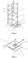
Figure 1 is a perspective view of a carrying robot according to a preferred embodiment of the present application. -
Figure 2 is a perspective view of a container transport unit according to the preferred embodiment of the present application. -
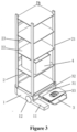
Figure 3 is a perspective view of a carrying robot according to another preferred embodiment of the present application. - Reference numerals in
Figures 1 to 3 :1 drive unit; 11 chassis frame; 12 drive wheel; 2 container storage unit; 21 support rail; 22 pallet; 3 container transport unit; 31 mounting frame; 32 lifting device; 33 telescopic fork tooth; 34 rotating device; 35 pose sensor; 36 positioning sensor; 4 container. - Two preferred embodiments of the present application are described below with reference to the drawings of the specification to make the technical contents of the embodiments clearer and easier to understand. The present application may be embodied by many different forms of embodiments, and the scope of protection of the present application is not limited to the embodiments disclosed herein.
- In the drawings, components with the same structure are represented by the same reference numerals, and components with similar structures or functions are represented by similar reference numerals. The dimensions and thickness of each component shown in the drawings are not shown to scale, and the present application does not limit the dimensions and thickness of each component. In order to make the illustrations clearer, the thickness of the components is appropriately exaggerated in some places of the drawings.
- When some components are described as 'on another component', the components may be placed directly on another component, or there may be an intermediate component, the components are placed on the intermediate component, and the intermediate component is placed on another component. When some components are described as 'mounted to' or 'connected to' another component, the components may be directly 'mounted to' or 'connected to' the other component, or there may be an intermediate component, and the components are 'mounted to' or 'connected to' another component through the intermediate component.
- As shown in
Figures 1 and 2 , a robot for carrying a container includes a drive unit 1, acontainer storage unit 2 and acontainer transport unit 3. - (1) The drive unit 1 is configured to drive the
container storage unit 2 and thecontainer transport unit 3, both of which are mounted on the drive unit to jointly move on the ground; - (2) the
container storage unit 2 is arranged above the drive unit 1 and configured to store thecontainer 4; and - (3) the
container transport unit 3 is arranged at one side of thecontainer storage unit 2 and configured to transport thecontainer 4 into thecontainer storage unit 2 or out of thecontainer storage unit 2 to a specified position. - The drive unit 1 includes a
chassis frame 11 anddrive wheels 12, where twodrive wheels 12 are provided and symmetrically mounted on two sides of thechassis frame 11. By the rotation of thedrive wheels 12, the advance, reverse, turn and in-situ rotation of the robot can be realized. - The
container storage unit 2 includessupport rails 21,pallets 22 and reinforcingribs 23. Thesupport rails 21 are located above the drive unit 1. Thesupport rails 21 are connected to each other by thepallets 22 and the reinforcingribs 23, and thepallets 22 are configured to stack the containers. - The
container storage unit 2 can store multiple containers. - Each of the
pallets 22 is separated in the middle. - The
container transport unit 3 includes aframe 31, alifting device 32, atelescopic fork tooth 33 and arotating device 34. One end of thelifting device 31 is connected with the support rails 21 and can slide up and down along a vertical direction of the support rails 21, and another end is connected with thetelescopic fork tooth 33 through therotating device 34. - The
telescopic fork tooth 33 can rotate along the z-axis through therotating device 34. - The
telescopic fork tooth 33 extends or retracts along the x direction. If therotating device 34 drives thetelescopic fork tooth 33 to rotate, a telescopic direction of thetelescopic fork tooth 33 also rotates. - The
container transport unit 3 further includes apose sensor 35 configured to identify a posture of the container above thetelescopic fork tooth 33, and apositioning sensor 36 configured to detect a position of the container. - The
pose sensor 35 may be a vision sensor or other sensor that can obtain pose information. - The
positioning sensor 36 may be a vision sensor or other sensor that can obtain pose information. - The process of the robot for carrying a container carrying the
container 4 to thecontainer storage unit 2 is as follows, the robot moves thecontainer transport unit 3 to a specified position through the liftingdevice 32, and rotates thetelescopic fork tooth 33 to a specified angle through therotating device 34, then extends thetelescopic fork tooth 33 to a position below thecontainer 4 to be transported, then lifts thecontainer 4 through the liftingdevice 32, then retracts thecontainer 4 through thetelescopic fork tooth 33, then rotates thetelescopic fork tooth 33 and thecontainer 4 to another specified angle through therotating device 34, then moves thecontainer 4 to a position above thepallet 22 through thetelescopic fork tooth 33, then lowers thecontainer 4 through the liftingdevice 32 to place the container on thepallet 22, and finally retracts thetelescopic fork tooth 33. - As shown in
Figures 2 and3 , a robot for carrying a container includes a drive unit 1, acontainer storage unit 2 and acontainer transport unit 3. - (1) The drive unit 1 is configured to drive the
container storage unit 2 and thecontainer transport unit 3, both of which are mounted on the drive unit to jointly move on the ground; - (2) the
container storage unit 2 is arranged above the drive unit 1 and configured to store thecontainer 4; and - (3) the
container transport unit 3 is arranged at one side of thecontainer storage unit 2 and configured to transport thecontainer 4 into thecontainer storage unit 2 or out of thecontainer storage unit 2 to a specified position. - The drive unit 1 includes a
chassis frame 11 and drivewheels 12, where two drivewheels 12 are provided and symmetrically mounted on both sides of thechassis frame 11. By the rotation of thedrive wheels 12, the advance, reverse, turn and in-situ rotation of the robot can be realized. - The
container storage unit 2 includes support rails 21,pallets 22 and reinforcingribs 23. The support rails 21 are located above the drive unit 1. The support rails 21 are connected to each other by thepallets 22 and the reinforcingribs 23, and thepallets 22 are configured to stack the containers. - The
container storage unit 2 can store multiple containers. - Each of the
pallets 22 is a flat plate connected with the support rails 21 on both sides. - The
container transport unit 3 includes aframe 31, alifting device 32, atelescopic fork tooth 33 and arotating device 34. One end of thelifting device 31 is connected with the support rails 21 and can slide up and down along a vertical direction of the support rails 21, and the other end is connected with thetelescopic fork tooth 33 through therotating device 34. - The
telescopic fork tooth 33 can rotate along the z-axis through therotating device 34. - The
telescopic fork tooth 33 can extend or retract along the x direction. If therotating device 34 drives thetelescopic fork tooth 33 to rotate, a telescopic direction of thetelescopic fork tooth 33 also rotates. - The
container transport unit 3 further includes apose sensor 35 configured to identify a posture of the container above thetelescopic fork tooth 33, and apositioning sensor 36 configured to detect a position of the container. - The
pose sensor 35 may be a vision sensor or other sensor that can obtain pose information, such as a radio frequency sensor. - The
positioning sensor 36 may be a vision sensor or other sensor that can obtain pose information, such a radio frequency sensor. - The process of the robot for carrying a container carrying the
container 4 to thecontainer storage unit 2 is as follows, the robot moves thecontainer transport unit 3 to a specified position through the liftingdevice 32, and rotates thetelescopic fork tooth 33 to a specified angle through therotating device 34, then extends thetelescopic fork tooth 33 to a position below thecontainer 4 to be transported, then lifts thecontainer 4 through the liftingdevice 32, then retracts thecontainer 4 through thetelescopic fork tooth 33, then rotates thetelescopic fork tooth 33 and thecontainer 4 to another specified angle through therotating device 34, then moves thecontainer 4 to a position above thepallet 22 through thetelescopic fork tooth 33, then lowers thecontainer 4 through the liftingdevice 32 to place the container on thepallet 22, and finally retracts thetelescopic fork tooth 33. - The preferred embodiments of the present application are described in detail above. It should be understood that various modifications and changes can be made in accordance with the concept of the present application by those skilled in the art without any creative efforts. The scope of protection is determined by the claims.
Claims (10)
- A robot for carrying a container, comprising a drive unit (1), a container storage unit (2) and a container transport unit (3), wherein the drive unit (1) is configured to carry the container storage unit (2) and the container transport unit (3) to jointly move; and the container storage unit (2) comprises one or more container storage spaces; andthe container transport unit (3) is arranged at one side of the container storage unit (2) and is configured to transport the container between the container storage spaces and a shelf;the container storage unit (2) comprises support rails (21), pallets (22) and reinforcing ribs, and the support rails (21), the pallets (22) and the reinforcing ribs are connected with each other to form one or more container storage spaces, andthe container transport unit (3) comprises a lifting device (31), a rotating device (34) and a telescopic fork tooth, one end of the lifting device (31) is connected with the support rails (21) and is slidable up and down along a vertical direction of the support rails (21), characterized in thatanother end of the lifting device (31) is connected with the telescopic fork tooth through the rotating device (34), the telescopic fork tooth is configured to extend and retract along a telescopic direction, the rotating device (34) drives the telescopic fork tooth to rotate, such that the telescopic direction of the telescopic fork tooth rotates.
- The robot for carrying a container according to claim 1, wherein the drive unit (1) comprises a chassis frame (11) and a drive wheel (12), and the drive wheel (12) is configured to drive the robot to move or stop.
- The robot for carrying a container according to claim 2, wherein motions of the robot comprise advance, reverse, turn and in-situ rotation.
- The robot for carrying a container according to claim 2, wherein two or more drive wheels (12) are provided.
- The robot for carrying a container according to claim 1, wherein the pallets (22) are configured to separate the one or more container storage spaces.
- The robot for carrying a container according to any one of claims 1 to 5, further comprising a container, wherein the one or more container storage spaces and the container are provided with machine-readable codes, and the container transport unit (3) further comprises a positioning sensor (36) and a pose sensor (35).
- The robot for carrying a container according to claim 6, wherein each of the machine-readable codes is a barcode or a two-dimensional barcode or a character string or an RFID.
- The robot for carrying a container according to claim 6, wherein the positioning sensor (36) is configured to detect a position of the container, and the positioning sensor (36) is a vision sensor or a radio frequency sensor.
- The robot for carrying a container according to claim 6, wherein the pose sensor (35) is configured to detect a pose of the container on the container transport unit (3), and the pose sensor (35) is a vision sensor or a radio frequency sensor.
- The robot for carrying a container according to claim 1, wherein each of the pallets (22) is a flat plate with an integral surface or each of the pallets (22) is hollowed or partitioned.
Applications Claiming Priority (1)
| Application Number | Priority Date | Filing Date | Title |
|---|---|---|---|
| PCT/CN2017/071280 WO2018129738A1 (en) | 2017-01-16 | 2017-01-16 | Robot for carrying container |
Publications (4)
| Publication Number | Publication Date |
|---|---|
| EP3569523A1 EP3569523A1 (en) | 2019-11-20 |
| EP3569523A4 EP3569523A4 (en) | 2020-09-30 |
| EP3569523C0 EP3569523C0 (en) | 2024-12-04 |
| EP3569523B1 true EP3569523B1 (en) | 2024-12-04 |
Family
ID=62839286
Family Applications (1)
| Application Number | Title | Priority Date | Filing Date |
|---|---|---|---|
| EP17891876.9A Active EP3569523B1 (en) | 2017-01-16 | 2017-01-16 | Robot for carrying container |
Country Status (5)
| Country | Link |
|---|---|
| US (2) | US11370107B2 (en) |
| EP (1) | EP3569523B1 (en) |
| JP (2) | JP6855025B2 (en) |
| SG (1) | SG11201906596SA (en) |
| WO (1) | WO2018129738A1 (en) |
Families Citing this family (36)
| Publication number | Priority date | Publication date | Assignee | Title |
|---|---|---|---|---|
| US20240017395A1 (en) * | 2017-01-16 | 2024-01-18 | Zhejiang Guozi Robot Technology Co., Ltd. | Robot for transporting cargo boxes |
| US11370107B2 (en) * | 2017-01-16 | 2022-06-28 | Zhejiang Guozi Robot Technology Co., Ltd. | Robot for transporting cargo boxes |
| US11465840B2 (en) | 2017-11-14 | 2022-10-11 | Hai Robotics Co., Ltd. | Handling robot |
| US12330870B2 (en) * | 2017-11-14 | 2025-06-17 | Hai Robotics Co., Ltd. | Handling robot |
| KR102385397B1 (en) | 2017-11-14 | 2022-04-14 | 하이 로보틱스 씨오., 엘티디. | Transport Robot and Transport Robot-Based Pickup Method |
| US12006143B2 (en) | 2017-11-14 | 2024-06-11 | Hai Robotics Co., Ltd. | Handling robot |
| US12103771B2 (en) | 2017-11-14 | 2024-10-01 | Hai Robotics Co., Ltd. | Handling robot |
| US11396424B2 (en) | 2017-11-14 | 2022-07-26 | Hai Robotics Co., Ltd. | Handling robot |
| DE102017131294A1 (en) * | 2017-12-23 | 2019-06-27 | Brose Fahrzeugteile Gmbh & Co. Kommanditgesellschaft, Coburg | Material supply system for a production plant |
| CN112512944B (en) * | 2018-05-22 | 2022-09-20 | 匹克八西普科技股份有限公司 | Cargo container and cargo logistics method |
| CN209160601U (en) * | 2018-09-07 | 2019-07-26 | 深圳市海柔创新科技有限公司 | a handling robot |
| EP3915904B1 (en) | 2019-01-21 | 2025-12-24 | Hai Robotics Co., Ltd. | Intelligent warehousing system, goods picking and placing method, and background processing terminal of intelligent warehousing system |
| US11542135B2 (en) | 2019-02-01 | 2023-01-03 | Hai Robotics Co., Ltd. | Handling robot |
| US11597598B2 (en) | 2019-02-01 | 2023-03-07 | Hai Robotics Co., Ltd. | Handling robot |
| CN209758195U (en) * | 2019-02-01 | 2019-12-10 | 深圳市海柔创新科技有限公司 | a handling robot |
| CN109998349A (en) * | 2019-05-07 | 2019-07-12 | 北京云迹科技有限公司 | A kind of box container system of standard |
| WO2020227381A1 (en) | 2019-05-07 | 2020-11-12 | Autonomous Shelf, Inc. | Systems, methods, computing platforms, and storage media for directing and controlling an autonomous inventory management system |
| CN110606305A (en) * | 2019-07-31 | 2019-12-24 | 深圳市海柔创新科技有限公司 | An intelligent sorting system, method, storage robot and processing terminal |
| CN211197466U (en) * | 2019-11-19 | 2020-08-07 | 深圳市海柔创新科技有限公司 | Carrying device and carrying robot with same |
| CN110920713A (en) * | 2019-12-05 | 2020-03-27 | 中山市晨旭科技有限公司 | Logistics vehicle |
| CN111422787B (en) * | 2020-04-24 | 2025-04-08 | 北京轩宇空间科技有限公司 | Mobile vehicle |
| CN212221331U (en) * | 2020-05-13 | 2020-12-25 | 北京极智嘉科技有限公司 | Transfer robot and warehouse logistics system |
| US12065310B2 (en) * | 2020-06-02 | 2024-08-20 | Prime Robotics Inc. | Systems, methods, computing platforms, and storage media for controlling an autonomous inventory management system |
| US12014321B2 (en) | 2020-06-02 | 2024-06-18 | Prime Robotics, Inc. | Systems, methods, computing platforms, and storage media for directing and controlling an autonomous inventory management system in a retail control territory |
| CN111470240A (en) * | 2020-06-05 | 2020-07-31 | 北京极智嘉科技有限公司 | Container carrying robot and using method thereof |
| CN111703799A (en) * | 2020-06-10 | 2020-09-25 | 北京极智嘉科技有限公司 | A handling robot, a container picking method, a container loading method and a warehousing logistics system |
| CN114161432A (en) * | 2020-09-10 | 2022-03-11 | 广东博智林机器人有限公司 | Fluid body material transporting robot |
| CN114291391B (en) * | 2021-12-21 | 2023-12-29 | 浙江博秦精密工业有限公司 | Small-size machined part transportation conveyor |
| JP7468503B2 (en) * | 2021-12-28 | 2024-04-16 | トヨタ自動車株式会社 | Transport robot |
| KR20230111026A (en) | 2022-01-17 | 2023-07-25 | 현대자동차주식회사 | Mobility and apparatus for loading and unloading cargo |
| CN114435832B (en) * | 2022-01-24 | 2023-06-27 | 合肥井松智能科技股份有限公司 | Material box carrying robot |
| USD1063283S1 (en) * | 2022-02-28 | 2025-02-18 | Hai Robotics Co., Ltd. | Loading and unloading device |
| CN114601296B (en) * | 2022-03-31 | 2023-09-01 | 河南云迹智能技术有限公司 | Target loading determining method and device for robot to execute loading transfer task |
| CN219906901U (en) * | 2023-05-31 | 2023-10-27 | 杭州海康机器人股份有限公司 | Handling device |
| CN116573320B (en) * | 2023-06-20 | 2026-01-20 | 北京京东乾石科技有限公司 | Robot control methods and devices, cargo handling systems |
| CN120003889B (en) * | 2025-03-10 | 2025-08-05 | 宏贤达科技集团有限公司 | An intelligent AGV warehouse robot |
Family Cites Families (24)
| Publication number | Priority date | Publication date | Assignee | Title |
|---|---|---|---|---|
| US4492504A (en) * | 1981-12-07 | 1985-01-08 | Bell & Howell Company | Materials handling system |
| FR2565952B1 (en) * | 1984-06-14 | 1987-04-24 | Redoute Catalogue | ROBOTIC HANDLING SELF-PROPELLED TROLLEY |
| JP2516825B2 (en) * | 1990-05-14 | 1996-07-24 | 日本電信電話株式会社 | Two-dimensional relative positioning method |
| JPH0747403B2 (en) * | 1990-05-22 | 1995-05-24 | インベストロニカ・ソシエダッド・アノニマ | Program-controlled box / container operation / transfer device |
| JP3183119B2 (en) * | 1995-08-28 | 2001-07-03 | 日本鋼管株式会社 | Layer unit transfer device |
| GB2336838B (en) | 1998-04-30 | 2001-11-21 | Indumat Gmbh & Co Kg | Driverless transport vehicle |
| US7850413B2 (en) | 2007-01-05 | 2010-12-14 | Kiva Systems, Inc. | System and method for transporting inventory items |
| DE102010001724B4 (en) * | 2010-02-09 | 2012-02-02 | Miksch Gmbh | shelf magazine |
| JP2013091366A (en) | 2011-10-25 | 2013-05-16 | Toyota Motor East Japan Inc | Automatic guided vehicle |
| CN102658542A (en) | 2012-05-07 | 2012-09-12 | 上海电机学院 | Rail type intelligent machine transporting truck |
| CA2923474C (en) * | 2013-09-09 | 2022-06-21 | Dematic Corp. | Autonomous mobile picking |
| US9002506B1 (en) * | 2013-09-25 | 2015-04-07 | Amazon Technologies, Inc. | Item retrieval using a robotic drive unit |
| JP6177927B2 (en) * | 2013-10-11 | 2017-08-09 | 株式会社日立製作所 | Transfer robot system |
| CA2980686A1 (en) * | 2015-03-23 | 2016-09-29 | Rajesh MANPAT | Method and system for optimizing movement of products using robotic drive units (rdus) in a warehouse environment |
| WO2016151505A1 (en) | 2015-03-23 | 2016-09-29 | Manpat Rajesh | Robotic drive unit with robotic inventory elevator |
| US9120622B1 (en) * | 2015-04-16 | 2015-09-01 | inVia Robotics, LLC | Autonomous order fulfillment and inventory control robots |
| US11167924B2 (en) * | 2015-06-24 | 2021-11-09 | HDS Mercury Inc. | Shelving system and power transfer device |
| CN205555211U (en) * | 2015-12-20 | 2016-09-07 | 华南理工大学广州学院 | Stereoscopic warehouse Z axle driven device |
| JP6510436B2 (en) * | 2016-02-12 | 2019-05-08 | 株式会社日立製作所 | Article conveying system, conveying apparatus and article conveying method |
| CN105730956B (en) | 2016-03-30 | 2017-10-17 | 南通大学 | Stacker with double deck |
| CN106005862A (en) | 2016-07-18 | 2016-10-12 | 广州广日智能停车设备有限公司 | Automatic storage warehouse equipment |
| CN106272415A (en) | 2016-08-30 | 2017-01-04 | 上海大学 | Omni-mobile transport robot |
| US10395152B2 (en) * | 2016-09-16 | 2019-08-27 | Amazon Technologies, Inc. | Amassing pick and/or storage task density for inter-floor transfer |
| US11370107B2 (en) * | 2017-01-16 | 2022-06-28 | Zhejiang Guozi Robot Technology Co., Ltd. | Robot for transporting cargo boxes |
-
2017
- 2017-01-16 US US16/466,382 patent/US11370107B2/en active Active
- 2017-01-16 EP EP17891876.9A patent/EP3569523B1/en active Active
- 2017-01-16 SG SG11201906596SA patent/SG11201906596SA/en unknown
- 2017-01-16 WO PCT/CN2017/071280 patent/WO2018129738A1/en not_active Ceased
- 2017-01-16 JP JP2019529624A patent/JP6855025B2/en active Active
-
2021
- 2021-03-01 JP JP2021031759A patent/JP7190518B2/en active Active
-
2022
- 2022-06-27 US US17/850,347 patent/US20220324095A1/en not_active Abandoned
Also Published As
| Publication number | Publication date |
|---|---|
| WO2018129738A1 (en) | 2018-07-19 |
| EP3569523C0 (en) | 2024-12-04 |
| US20220324095A1 (en) | 2022-10-13 |
| EP3569523A1 (en) | 2019-11-20 |
| US20200078936A1 (en) | 2020-03-12 |
| JP2021098609A (en) | 2021-07-01 |
| US11370107B2 (en) | 2022-06-28 |
| SG11201906596SA (en) | 2019-08-27 |
| EP3569523A4 (en) | 2020-09-30 |
| JP6855025B2 (en) | 2021-04-07 |
| JP2020500799A (en) | 2020-01-16 |
| JP7190518B2 (en) | 2022-12-15 |
Similar Documents
| Publication | Publication Date | Title |
|---|---|---|
| EP3569523A1 (en) | Robot for carrying container | |
| CN206569571U (en) | A kind of robot for carrying container | |
| KR102342280B1 (en) | Object handling systems and methods | |
| US20260008618A1 (en) | Robot | |
| US20220274775A1 (en) | Carrying device and transport robot having the same | |
| CN111731746B (en) | Transfer robot and warehouse logistics system | |
| CN108217038A (en) | A kind of robot and its method for carrying container | |
| CN210794517U (en) | Transfer robot | |
| CN210883786U (en) | Transfer robot | |
| EP3620409B1 (en) | Batch-based picking robot | |
| US12103771B2 (en) | Handling robot | |
| KR20170024046A (en) | Robotic object handling system, device and method | |
| CN208265098U (en) | The autonomous mobile robot of cargo is picked and placed for shelf | |
| CN118139798A (en) | Robotic pick wall system and method utilizing mobile target location assembly | |
| CN108974920B (en) | a handling robot | |
| US12330870B2 (en) | Handling robot | |
| CN106315099A (en) | Lifting transfer loader | |
| CN204727023U (en) | A kind of mobile stack type dense storage warehouse | |
| CN113460846A (en) | Tower crane type logistics express delivery transportation robot and control method thereof | |
| JP7554346B2 (en) | Method for managing a warehouse containing pneumatic tires equipped with transponders and arranged vertically in a stack | |
| EP3372541B1 (en) | Device and method for gripping and moving items | |
| CN204727025U (en) | The automatic vertical library of a kind of mobile stack type | |
| CN221215805U (en) | A unloader that is used for laser instrument coupled system to assemble automatically | |
| CN118323708A (en) | An automated warehouse and a material loading and conveying device thereof | |
| CN204737691U (en) | A walk capable lift for intensive thesaurus |
Legal Events
| Date | Code | Title | Description |
|---|---|---|---|
| STAA | Information on the status of an ep patent application or granted ep patent |
Free format text: STATUS: THE INTERNATIONAL PUBLICATION HAS BEEN MADE |
|
| PUAI | Public reference made under article 153(3) epc to a published international application that has entered the european phase |
Free format text: ORIGINAL CODE: 0009012 |
|
| STAA | Information on the status of an ep patent application or granted ep patent |
Free format text: STATUS: REQUEST FOR EXAMINATION WAS MADE |
|
| 17P | Request for examination filed |
Effective date: 20190814 |
|
| AK | Designated contracting states |
Kind code of ref document: A1 Designated state(s): AL AT BE BG CH CY CZ DE DK EE ES FI FR GB GR HR HU IE IS IT LI LT LU LV MC MK MT NL NO PL PT RO RS SE SI SK SM TR |
|
| AX | Request for extension of the european patent |
Extension state: BA ME |
|
| RIN1 | Information on inventor provided before grant (corrected) |
Inventor name: WU, WEIFENG Inventor name: ZHU, LINGFEN Inventor name: TAO, YIKUN Inventor name: ZHENG, HONGBO |
|
| DAV | Request for validation of the european patent (deleted) | ||
| DAX | Request for extension of the european patent (deleted) | ||
| A4 | Supplementary search report drawn up and despatched |
Effective date: 20200828 |
|
| RIC1 | Information provided on ipc code assigned before grant |
Ipc: B25J 5/00 20060101ALI20200824BHEP Ipc: B65G 1/04 20060101AFI20200824BHEP Ipc: B66F 9/07 20060101ALI20200824BHEP |
|
| TPAC | Observations filed by third parties |
Free format text: ORIGINAL CODE: EPIDOSNTIPA |
|
| STAA | Information on the status of an ep patent application or granted ep patent |
Free format text: STATUS: EXAMINATION IS IN PROGRESS |
|
| 17Q | First examination report despatched |
Effective date: 20231123 |
|
| GRAP | Despatch of communication of intention to grant a patent |
Free format text: ORIGINAL CODE: EPIDOSNIGR1 |
|
| STAA | Information on the status of an ep patent application or granted ep patent |
Free format text: STATUS: GRANT OF PATENT IS INTENDED |
|
| INTG | Intention to grant announced |
Effective date: 20240719 |
|
| GRAS | Grant fee paid |
Free format text: ORIGINAL CODE: EPIDOSNIGR3 |
|
| GRAA | (expected) grant |
Free format text: ORIGINAL CODE: 0009210 |
|
| STAA | Information on the status of an ep patent application or granted ep patent |
Free format text: STATUS: THE PATENT HAS BEEN GRANTED |
|
| AK | Designated contracting states |
Kind code of ref document: B1 Designated state(s): AL AT BE BG CH CY CZ DE DK EE ES FI FR GB GR HR HU IE IS IT LI LT LU LV MC MK MT NL NO PL PT RO RS SE SI SK SM TR |
|
| REG | Reference to a national code |
Ref country code: GB Ref legal event code: FG4D |
|
| REG | Reference to a national code |
Ref country code: CH Ref legal event code: EP |
|
| REG | Reference to a national code |
Ref country code: DE Ref legal event code: R096 Ref document number: 602017086624 Country of ref document: DE |
|
| REG | Reference to a national code |
Ref country code: IE Ref legal event code: FG4D |
|
| U01 | Request for unitary effect filed |
Effective date: 20241218 |
|
| U07 | Unitary effect registered |
Designated state(s): AT BE BG DE DK EE FI FR IT LT LU LV MT NL PT RO SE SI Effective date: 20250110 |
|
| U20 | Renewal fee for the european patent with unitary effect paid |
Year of fee payment: 9 Effective date: 20250127 |
|
| PG25 | Lapsed in a contracting state [announced via postgrant information from national office to epo] |
Ref country code: HR Free format text: LAPSE BECAUSE OF FAILURE TO SUBMIT A TRANSLATION OF THE DESCRIPTION OR TO PAY THE FEE WITHIN THE PRESCRIBED TIME-LIMIT Effective date: 20241204 |
|
| PG25 | Lapsed in a contracting state [announced via postgrant information from national office to epo] |
Ref country code: ES Free format text: LAPSE BECAUSE OF FAILURE TO SUBMIT A TRANSLATION OF THE DESCRIPTION OR TO PAY THE FEE WITHIN THE PRESCRIBED TIME-LIMIT Effective date: 20241204 |
|
| PG25 | Lapsed in a contracting state [announced via postgrant information from national office to epo] |
Ref country code: NO Free format text: LAPSE BECAUSE OF FAILURE TO SUBMIT A TRANSLATION OF THE DESCRIPTION OR TO PAY THE FEE WITHIN THE PRESCRIBED TIME-LIMIT Effective date: 20250304 |
|
| PG25 | Lapsed in a contracting state [announced via postgrant information from national office to epo] |
Ref country code: GR Free format text: LAPSE BECAUSE OF FAILURE TO SUBMIT A TRANSLATION OF THE DESCRIPTION OR TO PAY THE FEE WITHIN THE PRESCRIBED TIME-LIMIT Effective date: 20250305 |
|
| PG25 | Lapsed in a contracting state [announced via postgrant information from national office to epo] |
Ref country code: RS Free format text: LAPSE BECAUSE OF FAILURE TO SUBMIT A TRANSLATION OF THE DESCRIPTION OR TO PAY THE FEE WITHIN THE PRESCRIBED TIME-LIMIT Effective date: 20250304 |
|
| PG25 | Lapsed in a contracting state [announced via postgrant information from national office to epo] |
Ref country code: SM Free format text: LAPSE BECAUSE OF FAILURE TO SUBMIT A TRANSLATION OF THE DESCRIPTION OR TO PAY THE FEE WITHIN THE PRESCRIBED TIME-LIMIT Effective date: 20241204 |
|
| PG25 | Lapsed in a contracting state [announced via postgrant information from national office to epo] |
Ref country code: PL Free format text: LAPSE BECAUSE OF FAILURE TO SUBMIT A TRANSLATION OF THE DESCRIPTION OR TO PAY THE FEE WITHIN THE PRESCRIBED TIME-LIMIT Effective date: 20241204 |
|
| PG25 | Lapsed in a contracting state [announced via postgrant information from national office to epo] |
Ref country code: IS Free format text: LAPSE BECAUSE OF FAILURE TO SUBMIT A TRANSLATION OF THE DESCRIPTION OR TO PAY THE FEE WITHIN THE PRESCRIBED TIME-LIMIT Effective date: 20250404 |
|
| PG25 | Lapsed in a contracting state [announced via postgrant information from national office to epo] |
Ref country code: SK Free format text: LAPSE BECAUSE OF FAILURE TO SUBMIT A TRANSLATION OF THE DESCRIPTION OR TO PAY THE FEE WITHIN THE PRESCRIBED TIME-LIMIT Effective date: 20241204 |
|
| PG25 | Lapsed in a contracting state [announced via postgrant information from national office to epo] |
Ref country code: CZ Free format text: LAPSE BECAUSE OF FAILURE TO SUBMIT A TRANSLATION OF THE DESCRIPTION OR TO PAY THE FEE WITHIN THE PRESCRIBED TIME-LIMIT Effective date: 20241204 |
|
| PG25 | Lapsed in a contracting state [announced via postgrant information from national office to epo] |
Ref country code: MC Free format text: LAPSE BECAUSE OF FAILURE TO SUBMIT A TRANSLATION OF THE DESCRIPTION OR TO PAY THE FEE WITHIN THE PRESCRIBED TIME-LIMIT Effective date: 20241204 |
|
| PLBE | No opposition filed within time limit |
Free format text: ORIGINAL CODE: 0009261 |
|
| STAA | Information on the status of an ep patent application or granted ep patent |
Free format text: STATUS: NO OPPOSITION FILED WITHIN TIME LIMIT |
|
| REG | Reference to a national code |
Ref country code: CH Ref legal event code: L10 Free format text: ST27 STATUS EVENT CODE: U-0-0-L10-L00 (AS PROVIDED BY THE NATIONAL OFFICE) Effective date: 20251015 |
|
| 26N | No opposition filed |
Effective date: 20250905 |
|
| GBPC | Gb: european patent ceased through non-payment of renewal fee |
Effective date: 20250304 |
|
| PG25 | Lapsed in a contracting state [announced via postgrant information from national office to epo] |
Ref country code: GB Free format text: LAPSE BECAUSE OF NON-PAYMENT OF DUE FEES Effective date: 20250304 |
|
| PG25 | Lapsed in a contracting state [announced via postgrant information from national office to epo] |
Ref country code: IE Free format text: LAPSE BECAUSE OF NON-PAYMENT OF DUE FEES Effective date: 20250116 |
|
| REG | Reference to a national code |
Ref country code: CH Ref legal event code: U11 Free format text: ST27 STATUS EVENT CODE: U-0-0-U10-U11 (AS PROVIDED BY THE NATIONAL OFFICE) Effective date: 20260201 |
|
| U20 | Renewal fee for the european patent with unitary effect paid |
Year of fee payment: 10 Effective date: 20251231 |
|
| PGFP | Annual fee paid to national office [announced via postgrant information from national office to epo] |
Ref country code: CH Payment date: 20260201 Year of fee payment: 10 |