EP3569425B1 - A towing element assembly, a locking mechanism assembly and a flexible towing device for single-track vehicles comprising such a towing element assembly and such a locking mechanism assembly - Google Patents
A towing element assembly, a locking mechanism assembly and a flexible towing device for single-track vehicles comprising such a towing element assembly and such a locking mechanism assembly Download PDFInfo
- Publication number
- EP3569425B1 EP3569425B1 EP19174648.6A EP19174648A EP3569425B1 EP 3569425 B1 EP3569425 B1 EP 3569425B1 EP 19174648 A EP19174648 A EP 19174648A EP 3569425 B1 EP3569425 B1 EP 3569425B1
- Authority
- EP
- European Patent Office
- Prior art keywords
- locking mechanism
- assembly
- seat
- mechanism assembly
- lock
- Prior art date
- Legal status (The legal status is an assumption and is not a legal conclusion. Google has not performed a legal analysis and makes no representation as to the accuracy of the status listed.)
- Active
Links
- 230000007246 mechanism Effects 0.000 title claims description 359
- 230000008878 coupling Effects 0.000 claims description 8
- 238000010168 coupling process Methods 0.000 claims description 8
- 238000005859 coupling reaction Methods 0.000 claims description 8
- 238000004804 winding Methods 0.000 description 26
- 230000036461 convulsion Effects 0.000 description 9
- 230000000295 complement effect Effects 0.000 description 5
- 230000008859 change Effects 0.000 description 4
- 230000006378 damage Effects 0.000 description 4
- 230000007423 decrease Effects 0.000 description 4
- 208000027418 Wounds and injury Diseases 0.000 description 3
- 230000008901 benefit Effects 0.000 description 3
- 230000006872 improvement Effects 0.000 description 3
- 208000014674 injury Diseases 0.000 description 3
- 238000000034 method Methods 0.000 description 3
- 230000000694 effects Effects 0.000 description 2
- 239000013013 elastic material Substances 0.000 description 2
- 206010051602 Laziness Diseases 0.000 description 1
- 230000006978 adaptation Effects 0.000 description 1
- 230000000712 assembly Effects 0.000 description 1
- 238000000429 assembly Methods 0.000 description 1
- 230000003247 decreasing effect Effects 0.000 description 1
- 238000006073 displacement reaction Methods 0.000 description 1
- -1 for example Substances 0.000 description 1
- 238000004519 manufacturing process Methods 0.000 description 1
- 239000000463 material Substances 0.000 description 1
- 230000004048 modification Effects 0.000 description 1
- 238000012986 modification Methods 0.000 description 1
- 230000037081 physical activity Effects 0.000 description 1
- 230000037074 physically active Effects 0.000 description 1
- 239000002861 polymer material Substances 0.000 description 1
- 230000009467 reduction Effects 0.000 description 1
- 230000008439 repair process Effects 0.000 description 1
- 230000004044 response Effects 0.000 description 1
- 238000000926 separation method Methods 0.000 description 1
- 230000000087 stabilizing effect Effects 0.000 description 1
Images


Classifications
-
- B—PERFORMING OPERATIONS; TRANSPORTING
- B60—VEHICLES IN GENERAL
- B60D—VEHICLE CONNECTIONS
- B60D1/00—Traction couplings; Hitches; Draw-gear; Towing devices
- B60D1/14—Draw-gear or towing devices characterised by their type
- B60D1/18—Tow ropes, chains or the like
- B60D1/187—Tow ropes, chains or the like characterised by the connection to the towing vehicle or to the trailer
-
- B—PERFORMING OPERATIONS; TRANSPORTING
- B62—LAND VEHICLES FOR TRAVELLING OTHERWISE THAN ON RAILS
- B62J—CYCLE SADDLES OR SEATS; AUXILIARY DEVICES OR ACCESSORIES SPECIALLY ADAPTED TO CYCLES AND NOT OTHERWISE PROVIDED FOR, e.g. ARTICLE CARRIERS OR CYCLE PROTECTORS
- B62J27/00—Safety equipment
-
- B—PERFORMING OPERATIONS; TRANSPORTING
- B62—LAND VEHICLES FOR TRAVELLING OTHERWISE THAN ON RAILS
- B62K—CYCLES; CYCLE FRAMES; CYCLE STEERING DEVICES; RIDER-OPERATED TERMINAL CONTROLS SPECIALLY ADAPTED FOR CYCLES; CYCLE AXLE SUSPENSIONS; CYCLE SIDE-CARS, FORECARS, OR THE LIKE
- B62K13/00—Cycles convertible to, or transformable into, other types of cycles or land vehicle
- B62K13/02—Cycles convertible to, or transformable into, other types of cycles or land vehicle to a tandem
- B62K13/025—Cycles convertible to, or transformable into, other types of cycles or land vehicle to a tandem from two or more cycles
-
- B—PERFORMING OPERATIONS; TRANSPORTING
- B62—LAND VEHICLES FOR TRAVELLING OTHERWISE THAN ON RAILS
- B62K—CYCLES; CYCLE FRAMES; CYCLE STEERING DEVICES; RIDER-OPERATED TERMINAL CONTROLS SPECIALLY ADAPTED FOR CYCLES; CYCLE AXLE SUSPENSIONS; CYCLE SIDE-CARS, FORECARS, OR THE LIKE
- B62K27/00—Sidecars; Forecars; Trailers or the like specially adapted to be attached to cycles
- B62K27/10—Other component parts or accessories
- B62K27/12—Coupling parts for attaching cars or the like to cycle; Arrangements thereof
- B62K27/14—Resilient coupling parts
-
- B—PERFORMING OPERATIONS; TRANSPORTING
- B60—VEHICLES IN GENERAL
- B60D—VEHICLE CONNECTIONS
- B60D1/00—Traction couplings; Hitches; Draw-gear; Towing devices
- B60D1/14—Draw-gear or towing devices characterised by their type
- B60D1/18—Tow ropes, chains or the like
- B60D1/185—Tow ropes, chains or the like comprising a cable or chain winding device
-
- B—PERFORMING OPERATIONS; TRANSPORTING
- B60—VEHICLES IN GENERAL
- B60D—VEHICLE CONNECTIONS
- B60D1/00—Traction couplings; Hitches; Draw-gear; Towing devices
- B60D2001/001—Traction couplings; Hitches; Draw-gear; Towing devices specially adapted for use on vehicles other than cars
- B60D2001/003—Traction couplings; Hitches; Draw-gear; Towing devices specially adapted for use on vehicles other than cars for bicycles or motorbikes
-
- B—PERFORMING OPERATIONS; TRANSPORTING
- B62—LAND VEHICLES FOR TRAVELLING OTHERWISE THAN ON RAILS
- B62J—CYCLE SADDLES OR SEATS; AUXILIARY DEVICES OR ACCESSORIES SPECIALLY ADAPTED TO CYCLES AND NOT OTHERWISE PROVIDED FOR, e.g. ARTICLE CARRIERS OR CYCLE PROTECTORS
- B62J11/00—Supporting arrangements specially adapted for fastening specific devices to cycles, e.g. supports for attaching maps
- B62J11/20—Harnesses; Arms, e.g. for dog leads
Definitions
- the present invention relates to a towing element assembly for a flexible towing device for single-track vehicles, a locking mechanism assembly for a flexible towing device for single-track vehicles and a flexible towing device for single-track vehicles comprising such a towing element assembly and such a locking mechanism assembly.
- the flexible towing device according to the invention for single-track vehicles is used in the movement of two single-track vehicles interconnected by means of the flexible towing device, especially bicycles, preferably a pair of bicycles, wherein the bike in the front is ridden by an adult, and the bike in the back is ridden by a child.
- a towing device can be used.
- a commonly used towing device is a bar for towing children's bikes, also known as a bicycle tow bar.
- a tow bar is suitable for small children, typically aged 3-5, not yet able to properly control a bicycle.
- Such a towing device has the structure of a tow bar or rod.
- One end of the structure of the tow bar is articulately attached to the back portion of the frame of the parent's bike, usually by means of a grip under the saddle.
- the structure of the tow bar is able to move rockingly horizontally relative to the parent's bike but is not able to move vertically relative to the parent's bike.
- the structure of the tow bar is attached to the front part of the child's bike such that while riding, the front wheel of the child's bike is elevated above the ground.
- the structure of the tow bar is single-point mounted to the child's bike to the frame right under the handlebars or, more commonly, double-point mounted under the handlebars and to the front fork or the front wheel axle. In such a case, a child has little control of their bicycle.
- the front wheel of the child's bike is elevated, and the child follows the parent's bike practically without any effort.
- the document No. US 6,036,215 discloses an apparatus for linking two or more bicycles together in a tandem by means of a light-weight tubular member.
- the light-weight member is attached to a leading bicycle in a location near or on the seat and to the head tube of the trailing bicycle by a quick-release fastener.
- a separation means insures that the apparatus will automatically separate from the trailing bicycle in the event of excessive force being applied.
- An alignment means is provided to cause the trailing bicycle to track in a substantial alignment with the leading means.
- the apparatus in one embodiment, comprises a second attachment assembly.
- the second attachment assembly comprises a coupling and a coupling plug being mounted therewithin with a wedge and a screw.
- the coupling plug with the wedge and the screw are used do attach a first strap and buckle coupling assembly to the tubular member.
- the screw within the second attachment assembly of the apparatus is tightened to a predetermined torque, the torque determining the predetermined detachment force of the coupling plug from the tubular member, releasing thereby said tubular member from the second attachment assembly.
- said bicycle tow bar is characterized by providing a highly rigid connection between the parent's and the child's bikes. Consequently, with a child riding a bike in an unstable manner, making movements aimed at keeping his or her balance, the rigidity of the tow bar disturbs these movements, causing an undesired disturbance to the child's riding. Such a disturbance hampers the balancing movements, resulting in a child swaying strongly and even falling off a bike.
- Another problem of prior-art tow bars is that a child may not keep the right position on a towed bike, for example out of laziness or fatigue. That is, a child riding such a bike may tilt to the right or left side.
- the tow bar is subjected to very strong torsional forces, which may damage it while riding, necessitating its repair or replacement and, in extreme cases, causing a child to fall together with a bike.
- children aged 6-8 are substantially capable of covering the entire route without help, except for certain parts of it, especially on the way back.
- the tow bar is not needed and so its high weight, large size and a troublesome method of attaching and detaching it pose a significant difficulty to the parent.
- the tractive effort of the parent amplifies the child's injuries.
- the parent's fall inevitably causes the child to fall too and suffer injuries.
- the present disclosure relates to a towing element assembly for a flexible towing device for single-track vehicles, comprising a towing element assembly and a locking mechanism assembly according to the invention.
- the towing element assembly according to the disclosure is adapted for mounting on a single-track vehicle and comprises a flexible towing element, a lock, wherein the lock is attached to one of the ends of the flexible towing element, and wherein the lock is configured to be detachably mounted in the seat of the locking mechanism assembly according to the invention.
- the lock of the towing element comprises a component having a shape selected from among a hemisphere, a ball, a disc, a half cone, a cone, a double cone, a bipyramid, a flat bar with recesses, for releasable fitting in the locking mechanism assembly according to the invention.
- the towing element assembly comprises also a bracket for mounting this assembly on a single-track vehicle.
- the present invention relates to a locking mechanism assembly for a flexible towing device for single-track vehicles, wherein the flexible towing device comprises a towing element assembly and a locking mechanism assembly.
- the locking mechanism assembly is adapted for mounting on a single-track vehicle and comprises a first portion of the body comprising a half-seat means, a second portion of the body comprising a half-seat means, wherein the half-seats means of the corresponding first and the second portion of the body form together a seat, the seat being configured for detachable coupling the towing element assembly, wherein the seat of the locking mechanism assembly is configured to assure a release force for providing releasing the towing element assembly when said release force is applied to the locking mechanism assembly via said towing element assembly, a first axis arranged in substantially the main direction of the locking mechanism assembly and defining a main axis of said mechanism, a second axis arranged laterally to the main direction of the locking mechanism assembly and defining a lateral axis
- the locking mechanism assembly comprises an adjusting mechanism for setting and/or adjusting the release force F.
- the half-seat means of the first portion of the body seat and the half-seat means of the second portion of the body are configured to assure the release force being constant across the entire angular range of operation of the seat.
- the first and the second portion of the body of the locking mechanism assembly is each shaped like a teaspoon and comprises a half-seat means in the form of a recess, wherein the first and the second portion of the body each comprises a notch arranged laterally along the lateral and configured to assure the first release force substantially along said axis having a maximum value, and an arched notch (59) arranged along the lateral axis and configured to assure the second release force substantially along said axis having a minimum value.
- each notch of the first and the second portion of the locking mechanism assembly is arranged independently so that the angle between the lateral axis and the main axis at is in the range from 0° to 80°, preferably from 0° to 70°, more preferably from 0° to 65°, and most preferably from 0° to 35°.
- the first and the second portion of the body is each shaped like a flat bar with a rounded end and comprises a notch arranged along the lateral axis and configured to assure the second release force substantially along said axis having a value substantially zero, and a recess arranged along the rounded end between the notch and the main axis and configured to assure the first release force along said track.
- each notch of the first and the second portion is arranged independently so that the angle between the lateral axis and the main axis is in the range from 80° to 90°, preferably from 70° to 90°.
- the half-seat means of the first portion of the body seat and a half-seat means of the second portion of the body are configured to assure to said seat said first release force directed toward the locking mechanism assembly within an angular range between the man axis and the lateral axis of 0° to 80°, preferably 0° to 70°, more preferably 0° to 65° and most preferably 0° to 35°, and said second release force out of the angular range of the first release force.
- the locking mechanism assembly comprises also a gyroscope for releasing the towing element assembly during a fall of a single-track vehicle on which the locking mechanism is mounted.
- the locking mechanism assembly comprises also a bracket for mounting this assembly on a single-track vehicle.
- the present disclosure relates to a flexible towing device for single-track vehicles.
- the flexible towing device according to the present disclosure comprises a locking mechanism assembly according to the invention and a towing element assembly, as described above.
- the present invention provides a flexible towing device for single-track vehicles providing a child with a greater freedom of movement on a bike ridden after the parent's bike.
- the flexible towing device for single-track vehicles allows a child to follow the parent's bike within a close range therefrom, determined by the length of the flexible towing device. A child rides a bike within this area freely, practically independently of the parent. However, when a child is riding a bike within a distance from the parent's bike determined by the length of the flexible towing device, especially after the parent's bike, the child is using the parent's tractive effort, thus utilizing the towing function of the towing device according to the present disclosure for single-track vehicles.
- the device In the case of occurrence of an event resulting in generation of a large force acting on a child's bike through the flexible towing device according to the present disclosure, the device is released, and the child's bike is disconnected from the parent's bike to avoid a dangerous situation or a fall.
- Such event is, for example, a sudden decrease in the speed of a child's bike relative to the speed of the parent's bike.
- a decrease in the speed of a child's bike does not cause a strong disturbance to his or her balance or result in their fall.
- the flexible towing device is disconnected. The child does not be dragged behind the parent's bike until the parent stops and, consequently, the child's injuries would practically be no greater than if suffered during riding a bike independently of the parent.
- the flexible towing device for single-track vehicles illustrated in the attached figures includes reference numbers of individual components, wherein the components corresponding to one another in terms of their design and/or function are marked with the same reference numbers.
- the flexible towing device for single-track vehicles is used for interconnecting two single-track vehicles.
- one of the single-track vehicles is a leading vehicle, which, in a pair of interconnected single-track vehicles, moves as the first one, together with the second single-track vehicle, being a led vehicle, which, in principle, follows the leading vehicle.
- the single-track vehicle is, without limitations, a bicycle.
- the leading single-track vehicle is, without limitations, an adult's bicycle, ridden by an adult, preferably a parent.
- the led vehicle is, without limitations, a children's bike ridden by a child, preferably a child having sufficient bike riding skills.
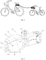
- the flexible towing device for single-track vehicles comprises a towing element assembly 1 and a locking mechanism assembly 50 according to the invention.
- the towing element assembly 1 comprises a flexible towing element 2 having a length, being an element interconnecting two single-track vehicles and determining the scope of movement within which two single-track vehicles are movable relative to each other. Said scope is determined by the length of the flexible towing element 2.
- the length of the flexible towing element 2 is selected such that the scope of movement determined by it allows single-track vehicles to be ridden freely relative to each other.
- the length of the flexible towing element 2 is not excessively long to ensure that the scope of movement between two single-track vehicles is not too big.
- the length of the flexible towing element 2 ranges from 0,7 to 5 m, preferably from 2 to 3,5 m.
- said flexible towing element 2 when single-track vehicles are moving relative to each other within the scope of the movement, within the length of the flexible towing element 2, said flexible towing element 2 does not transfer any forces between the first and the second single-track vehicle.
- said flexible towing element 2 when single-track vehicles are moving relative to each other within a distance equal to the length of the flexible towing element 2 and, substantially one behind the other, said flexible towing element 2 is tightened and transfers the towing force from the leading single-track vehicle to the led single-track vehicle.
- said towing device does not upset the balance of any of the single-track vehicles while mobile.
- the flexible towing element 2 does not pose a threat of knocking at least one of the single-track vehicles out of balance or a threat of it falling. In addition, the flexible towing element 2 does not pose such threat also in a situation where the led single-track vehicle overtakes the leading vehicle within the scope of the movement.
- the towing element assembly 1 comprises also a lock 3 attached to one of the ends of the flexible towing element 2.
- the lock 3 is adapted for detachable coupling in the locking mechanism assembly 50 according to the invention of the flexible towing device for single-track vehicles.
- the towing element assembly 1 is adapted for mounting on one of the single-track vehicles.
- the mounting of the towing element assembly 1 on a single-track vehicle is effected by means of tying the flexible towing element 2 to said single-track vehicle.
- the towing element assembly 1 comprises a grip for mounting the towing element assembly 1 on a single-track vehicle.
- the grip 4 constitutes a bracket for mounting the towing element assembly 1 on a single-track vehicle.
- the grip 4 is attached to the flexible towing element 2 on the opposite side of the lock 3.
- the towing element assembly 1 comprises a winding mechanism 5 for winding or unwinding the flexible towing element 2.
- the winding mechanism 5 allows adjusting the length of the flexible towing element 2 thus adjusting the above-mentioned scope of movement of single-track vehicles relative to each other.
- the winding mechanism 5 allows automatic winding of the flexible towing element 2 of the towing element assembly 1 following its releasing from the locking mechanism 50 according to the invention.
- the winding mechanism 5 continually keeps the flexible towing element 2 slightly tightened between single-track vehicles interconnected by means of the flexible towing device according to the present disclosure.
- the length of the flexible towing element is adjusted as bikes are moving, whereby the functionality of releasing following application of the force F is kept, as is described in detail below.
- the winding mechanism 5 comprises a grip 4 for mounting said assembly 5 on a single-track vehicle.
- the grip 4 constitutes a bracket for mounting the winding mechanism on a single-track vehicle, as shown in Fig. 8 .
- the grip 4 is located on the winding mechanism 5 on its opposite side relative to the flexible towing element 2.
- the locking mechanism assembly 50 comprises a seat 51 adapted for releasable receiving the lock 3 of the towing element assembly 1. This means that, if necessary, the lock 3 of the towing element assembly 1 is released from the seat 51 of the locking mechanism assembly 50 according to the invention.
- the locking mechanism assembly 50 is adapted for mounting on a second one of single-track vehicles.
- the locking mechanism assembly 50 comprises a grip 52 for mounting the locking mechanism assembly 50 on a single-track vehicle.
- the grip 51 constitutes a bracket, as shown in Figs. 2 to 4 , for mounting the locking mechanism assembly 50 according to the invention on a single-track vehicle.
- the towing element assembly 1 is mounted on a led single-track vehicle, whereas the locking mechanism assembly 50 is mounted on a leading single-track vehicle.
- the assemblies 1, 50 of the flexible towing device according to the present disclosure can be installed on single-track vehicles in a reverse configuration. Namely, the towing element assembly 1 is mounted on a leading single-track vehicle, whereas the locking mechanism assembly 50 according to the invention is mounted on a lead single-track vehicle.
- One of the towing element assembly 1 and the locking mechanism assembly 50 is mounted on a leading single-track vehicle in a spot ensuring a strong and stable connection of this assembly 1, 50 to the vehicle and allowing unhindered riding of such a vehicle.
- the selected assembly 1, 50 is mounted on the frame of the bicycle under the saddle.
- the second of the towing element assembly 1 and the locking mechanism assembly 50 is mounted on a lead single-track vehicle in a spot ensuring a strong and stable connection of this assembly 1, 50 to the vehicle and allowing unhindered riding of such a vehicle.
- the selected assembly 1, 50 is mounted to the frame of the bicycle within the handlebar, preferably on the stem of the handlebar to which rotatable attached is the fork of the front wheel.
- the towing element assembly 1 and/or the locking mechanism assembly 50 is integrated with the frame of a specific single-track vehicle.
- the towing element assembly 1 and/or the locking mechanism assembly, respectively is welded to the frame of a specific single-track vehicle at a spot, as indicated above by way of example.
- At least one of the lock 3 of the towing element assembly 1 and the seat 51 of the locking mechanism assembly 50 according to the invention is configured such that following applying a predefined force F to the lock 3 it is released from the seat 51.
- the release force F is applied to the lock 3 by means of the flexible towing element 2.
- the release force F is a force acting on the lock 3 of the towing element assembly 1 directed from the seat 51 of the locking mechanism assembly 50 according to the invention, which causes decoupling of the lock 3 and its sliding out of the seat 51.
- the release force F is generated by an event acting substantially directly on at least one of the components of the towing element assembly 1, particularly the flexible towing element 1.
- One of such events is, for example, an attempt at a sudden and/or firm displacement of one of single-track vehicles beyond the scope of movement defined by the length of the flexible towing element 2 of the towing element assembly 1, resulting, for example, from a sudden decrease in the speed of the led single-track vehicle relative to the leading single-track vehicle or a fall of the led single-track vehicle.
- the flexible towing element 2 pulls the lock 3 generating the release force F to act on it and, consequently, a release of the locking mechanism assembly 50 from the seat 51.
- Another event of this type occurs when an obstacle gets between the leading single-track vehicle and the led single-track vehicle or when the led single-track vehicle overtakes the leading single-track vehicle whose speed for some reason is decreased or which suddenly stops.
- Such event is particularly probable when single-track vehicles are not moving in line, that is, when the led single-track vehicle is ridden misaligned relative to the leading single-track vehicle or when both single-track vehicles are ridden next to one another.
- the flexible towing element 2 stops on said obstacle and is pulled, thus the release force F acting on the lock 3 is generated and said lock 3 shall be released from the seat 51 of the locking mechanism assembly 50 according to the invention.
- the jerk that is, the release force F generated and acting on the lock 3 of the towing element assembly 1 causing it to be released from the seat 51 of the locking mechanism 50 is big enough to disconnect the towing element assembly 1 from the locking mechanism assembly 50, and at the same time small enough not to significantly upset the balance of any of the persons riding the single-track vehicles or cause them to fall.
- the jerk disrupts the movement of at least one of the persons riding the single-track vehicles but is small enough to allow such a person to remain in control of their vehicle.
- the release force F does not pose a significant threat when a pedestrian is the obstacle.
- the creator has experimentally proven that the release force F, as described above, falls within the range of between 20 and 800 N, preferably from 50 to 300 N, and most preferably from 60 to 200 N.
- configuration of the release force F in the flexible towing device according to the present disclosure for single-track vehicles is performed on at least one of the lock 3 of the towing element assembly 1 and the seat 51 of the locking mechanism assembly 50 according to the invention.
- the release force F is configured such that following it being applied to the lock 3 as described above, said lock 3 of the towing element assembly 1 is released from the seat 51 of the locking mechanism assembly 50.
- the lock 3 of the towing element 1 comprises an adjusting mechanism 6 for setting and/or adjusting the lock 3 such that it is released from the seat 51 of the locking mechanism assembly 50 following application of the release force F.
- the locking mechanism assembly 50 comprises an adjusting mechanism 53 for setting and/or adjusting the locking mechanism assembly 50 such that the lock 3 of the towing element assembly 1 is released from the seat 51 following application of the release force F.
- the lock 3 of the towing element assembly 1 is equipped with the adjusting mechanism 6, while the locking mechanism assembly 50 according to the invention does not comprise any adjusting mechanisms.
- setting and/or adjusting the release force F in the flexible towing device according to the present invention for single-track vehicles is provided solely by means of the adjusting mechanism 6 of the lock 3 of the towing element assembly.
- the locking mechanism assembly 50 according to the invention is equipped with the adjusting mechanism 53, whereas the lock 3 of the towing element assembly comprises no adjusting mechanisms.
- setting and/or adjusting the release force F in the flexible towing device according to the invention for single-track vehicles is provided solely by means of the adjusting mechanism 53 of the locking mechanism assembly 50.
- both the lock 3 and the locking mechanism assembly 50 according to the invention are each equipped with the adjusting mechanisms 6, 53 of the release force F, respectively.
- the adjusting mechanism 6, 53 for setting and/or adjusting the release force F of the flexible towing device according to the present disclosure for single-track vehicles is realized, for example, but without limitations, mechanically, pneumatically, hydraulically, electrically, magnetically or by means of combination of these methods.
- the adjusting mechanism 6, 53 is realized by means of using an elastic material to manufacture the lock 3 of the towing element assembly 1 and the locking mechanism assembly 50 according to the invention, respectively.
- both the lock 3 and/or the seat 51 are deformed following application of the release force F, causing decoupling and sliding of the lock 3 of the towing element assembly 1 out of the seat 51 of the locking mechanism assembly 50.
- the elastic material is, for example, but without limitations, a polymer material, for example, rubber.
- the setpoint of the release force F is permanently factory-set by selecting a material having properties required to release the lock 3 of the towing element assembly 1 from the seat 51 of the locking mechanism assembly 50, as described above.
- the mechanical adjusting mechanism 6, 53 is realized, for example, but without limitations, by means of a spring provided in the lock 3 of the towing element assembly 1 and in the locking mechanism assembly 50, respectively, suitable for the mechanism 6, 53.
- the setpoint and/or adjustment of the adjusting mechanism 6, 53 is realized by setting or adjusting the spring load.
- the setpoint of the release force F of the mechanical adjusting mechanism 6, 53 can be factory-set permanently or can be adjusted as needed by the manufacturer or user of the flexible towing device according to the present disclosure for single-track vehicles.
- the pneumatic/hydraulic adjusting mechanism 6, 53 is realized, for example, but without limitations, by means of a pneumatic/hydraulic cylinder provided in the lock 3 of the towing element assembly 1 and in the locking mechanism assembly 50, respectively, suitable for the mechanism 6, 53.
- the setpoint and/or adjustment of the adjusting mechanism 6, 53 is realized by setting or adjusting the pressure of a pneumatic/hydraulic medium or the flow of such medium between the connected chambers of the pneumatic/hydraulic cylinder.
- the setpoint of the release force F of the pneumatic/hydraulic adjusting mechanism 6, 53 can be factory-set permanently or can be adjusted as needed by the manufacturer or user of the flexible towing device according to the present invention for single-track vehicles.
- the electrical adjusting mechanism 6, 53 is realized, for example, but without limitations, by means of an electrical or electronic system provided in the lock 3 of the towing element assembly 1 and in the locking mechanism assembly 50, respectively, suitable for the mechanism 6, 53.
- the electrical adjusting mechanism 6, 53 comprises a sensor for detecting the force applied to the lock 3 of the towing element 1 and for generating the sensor signal.
- the electrical adjusting mechanism 6, 53 comprises execution elements, which, depending on the sensor signal, cause the lock 3 of the assembly to be released from the seat 51 of the locking mechanism assembly 50.
- the sensor If the force applied to the lock 3 is equal to or greater than the release force F, the sensor generates a release signal transmitted to the execution elements in response to which signal the execution elements release the lock 3 of the towing element assembly from the seat 51 of the locking mechanism assembly 50.
- the setpoint of the release force F of the electrical adjusting mechanism 6, 53 can be factory-set permanently or can be adjusted as needed by the manufacturer or user of the flexible towing device according to the present disclosure for single-track vehicles using the adjusting means implemented in the electrical adjusting mechanism 6, 53.
- the magnetic adjusting mechanism 6, 53 is realized, for example, but without limitations, by means of a magnet provided in the lock 3 of the towing element assembly 1 and in the locking mechanism assembly 50, respectively, suitable for the mechanism 6, 53.
- the power of the magnet is selected such that following applying a force to the lock 3 of the towing element assembly 1 being equal to or greater than the release force, the lock 3 is released from the seat 51 of the locking mechanism assembly 50.
- the magnet is a permanent magnet or an electromagnet.
- the setpoint of the release force F of the magnetic mechanism 6, 53 is permanently factory-set by selecting a magnet having a magnetic force suitable for releasing the lock 3 of the towing element assembly 1 from the seat 51 of the locking mechanism assembly 50, as described above.
- the setpoint of the release force F of the magnetic adjusting mechanism 6, 53 can be factory-set permanently or can be adjusted as needed by the manufacturer or user of the flexible towing device according to the present disclosure for single-track vehicles using the adjusting means implemented in the magnetic adjusting mechanism 6, 53.
- At least one of the lock 3 of the towing element assembly 1 and the seat 51 of the locking mechanism assembly 50 according to the invention is configured such that following applying a predetermined force F to the lock 3 the lock 3 is released from the seat 51 as described above, wherein the release force F is variable depending on the angle of its application relative to the locking mechanism assembly 50.
- the release force F changes linearly with the angle, wherein the release force F has the greatest value Fo when directed substantially along the main axis O R of the locking mechanism assembly 50 according to the invention, consequently, along the main axis O of the single-track vehicle to which the locking mechanism assembly 50 is attached, and the smallest value of F B , when directed at a substantially right angle relative to the main axis O R of the locking mechanism assembly 50 and, consequently, is directed at a substantially right angle relative to the man axis O of such single-track vehicle.
- the release force F changes non-linearly, for example, but without limitations, exponentially together with the angle, from the maximum value of the release force Fo to the minimum value of the release force F B , where the forces Fo and F B are defined, as described above.
- the release force F is constant within a certain angular range around the main axis O R of the locking mechanism assembly 50, which force corresponds to the release force Fo, as described above, whereas beyond this angle, the release force F decreases in steps to a smaller release force corresponding to the release force F B , as described above, or is equal to substantially zero.
- the lock 3 of the towing element assembly 1 is released from the seat 51 of the locking mechanism assembly 50 substantially automatically, substantially without applying any force thereto.
- the lock 3 of the towing element assembly 1 comes out of the seat of the locking mechanism assembly 50 substantially by itself.
- the angle falls within the range of 0° to 80°, preferably 0° to 70°, preferably 0° to 65°, and most preferably 0° to 35°, wherein this angle is defined, as described above.
- the jerk generated by the flexible towing element 2 of the towing element assembly 1, being directed laterally or backward relative to the direction of travel is smaller, thus causing a reduction of a particularly dangerous lateral or backward disturbance of balance, increasing the safety of riding with a flexible towing device according to the present disclosure for single-track vehicles.
- the embodiment in which the release force F disappears is particularly preferred when the led single-track vehicle overtakes the leading single-track vehicle.
- the lock 3 of the towing element assembly 1 takes such an angle in the seat 51 of the locking mechanism assembly 50 that it falls out of this seat automatically without generating a jerk on any of the single-track vehicles, thus even improving the safety of riding with the flexible towing device according to the present disclosure for single-track vehicles.
- the flexible towing device comprises an auxiliary mechanism which facilitates introducing the lock 3 into the seat 51 of the locking mechanism assembly 50.
- the auxiliary mechanism is a cam mechanism, in which a rotation of the lever connected to the cam causes, respectively, adaptation of the shape of the lock 3 or opening the seat 51, allowing the lock 3 to be introduced into the seat 51 without using force.
- the lever is turned back to restore the initial shape of the lock 3 and/or to close the seat, thus providing a ready for operation flexible towing device according to the present disclosure for single-track vehicles.
- the auxiliary mechanism/auxiliary mechanisms are integrated with the adjusting mechanism 6 of the towing element assembly 1 and/or the adjusting mechanism 53 of the locking mechanism assembly 50, respectively.
- the flexible towing device comprises a towing element assembly 1 and a locking mechanism assembly 50 according to the invention.
- the towing element assembly 1 comprises a flexible towing element 2 in the form of a rope (not shown in the figures) and a lock 3 in the form of a rigid ball, attached to one of the ends of the flexible towing element 2.
- the towing element assembly 1 comprises a winding mechanism 5 of the flexible towing element for winding the flexible towing element 2, adjusting the length of this flexible towing element 2 and/or winding it following its release from the locking mechanism assembly 50, analogously as described above.
- the winding mechanism 5 is attached to the second end of the flexible towing element 2.
- the towing element assembly 1 comprises a bracket 4 for mounting the towing element assembly 1 on a single-track vehicle, wherein the bracket 4 is located on the winding mechanism 5, as shown in Fig. 8 .
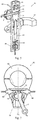
- the locking mechanism assembly 50 comprises a first portion 54 of the body, said portion being shaped like a teaspoon, comprising a recess constituting a half-seat 55 of the first portion of the body, and a second portion 56 of the body, said portion being shaped like a teaspoon, comprising a recess constituting a half-set 57 of the second portion of the body.
- the first and the second portion of the body 54 and 56 are hingeinterconnected such that they change their respective positions relative to each other.
- the first and the second teaspoon-shaped portion 54 and 56 of the body each comprises a protrusion directed substantially along the main axis O R of the locking mechanism assembly 50, which, following mounting of said mechanism on a single-track vehicle, extends in the same direction as the main axis O of said vehicle.
- the first and the second teaspoon-shaped portion 54 and 56 of the body each comprises arched notches on the opposite sides of these portions 54, 55, directed substantially perpendicular to the main axis O R of the locking mechanism assembly 50.
- the locking mechanism assembly 50 comprises a bracket 60 for mounting the locking mechanism assembly on a single-track vehicle.
- the locking mechanism assembly 50 comprises an adjusting mechanism 53 for adjusting the release force F of the locking mechanism assembly 50.
- the adjusting mechanism 53 comprises a spring acting on one of the portions 54, 56 of the body of the locking mechanism assembly 50 and pushing the portions 54, 56 of the body toward each other thus adjusting the release force F of the locking mechanism assembly 50. Due to the above-described shape of the portions 54, 56, the release force F has a different value depending on the direction of its application to the lock 3 in the form of a ball relative to the portions 54, 56 of the body of the locking mechanism assembly 50.
- the release force F in a direction substantially within the main axis O R of the locking mechanism assembly 50, the release force F has a value corresponding to the release force F R of the locking mechanism assembly 50 due to the presence of the protrusions, as shown in Fig. 2 .
- the release force F in the direction substantially perpendicular to the main axis O R of the locking mechanism assembly 50, both in one or the other lateral direction, the release force F has a value smaller than the release force Fo and corresponding to the release force F B due to the presence of the notches, as shown in Fig. 2 .
- the towing element assembly 1 is mounted on one of the single-track vehicles, while the locking mechanism assembly 50 is mounted on the other one of the single-track vehicles such that the main axis O R of the locking mechanism assembly 50 is directed in the same direction as the main axis O of the vehicle to which said locking mechanism assembly 50 is attached.
- the lock 3 in the form of a ball is located in the seat 51 between the portions 54 and 56 of the body of the locking mechanism 50.
- the release force F of the seat 51 is set by means of the adjusting mechanism 53 before or after placing the lock 3 in the form of a ball in said seat 51 of the locking mechanism assembly 50.
- the lock 3 in the form of the ball is rotatable substantially freely in the seat 51 such that the flexible towing element 2 can take any orientation relative to the slot of the seat 51 of the locking mechanism assembly 50.
- substantially freely means that the friction forces between the lock 3 of the towing element assembly 1 and the seat 51 of the locking mechanism assembly 50 are very small and thus negligible.
- the lock 3 of the towing element assembly 1 is slightly clamped inside the seat 51 of the locking mechanism assembly 50 such that the lock 3 rotates in the seat 51 with a slight constraint.
- the constraint of the rotation of the lock 3 in the seat 51 does not affect the release force Fo and F B , respectively, but only constrains the freedom of movement of the lock 3 in the seat 51, resulting in improving the safety of use of the flexible towing device according to the present disclosure for single-track vehicles.
- Said safety improvement results, for example, but without limitations, from thus substantially preventing the lock 3 from taking a position in the seat 51 that would be conducive to the flexible towing element 2 being pulled into the wheel of the single-track vehicle to which the locking mechanism assembly 50 is attached.
- the force acting on the towing device is greater than or equal to the force set on the seat 51 of the locking mechanism assembly 50 by means of the adjusting mechanism 6, it constitutes the release force F releasing the lock 3 in the form of a ball from the seat 51 formed by the half-seats 55 and 57 of the first and the second portion 54 and 56, respectively, of the body of the locking mechanism assembly 50.
- the force applied to such a lock 3 must be greater than or equal to the force corresponding to the release force Fo. If the force transferred to the lock 3 is directed substantially perpendicular to the main axis O R of the locking mechanism assembly 50, then, in order for the lock 3 in the form of a ball to be released, the force applied to such a lock 3 must be greater than or equal to the force corresponding to the release force F B , wherein, as described above, the release force Fo is greater than the release force F B .
- the jerk releasing the lock 3 of the towing element assembly 1 from the locking mechanism assembly 50 is less powerful in the lateral direction, thus resulting in a smaller disruption of balance when the led single-track vehicle is moving next to the leading single-track vehicle or then the led single-track vehicle overtakes the leading single-track vehicle.
- the lock 3 can also have a different shape.
- the lock 3 of the towing element assembly 1 may have any shape allowing its rotation in the seat 51 of the locking mechanism assembly 50 substantially at least horizontally.
- the lock 3 may be shaped like a disc with an ellipsoidal cross-section, a double cone, a pyramid, etc.
- the shape of the recesses of the half-seats 55, 57 of the first and the second portion 54, 56, respectively, of the body of the locking mechanism assembly 50 is complementary with such other selected shapes of the lock 3 of the towing element assembly 1.
- the flexible towing device for single-track vehicles having a ball-shaped lock 3 and teaspoon-shaped portions 54 and 56 of the body, as described above.
- the seat 51 of the locking mechanism assembly 50 is set permanently, while the lock 3 has an inherently implemented release force F or comprises an adjusting mechanism 7 for adjusting such release force F.
- the lock 3 changes shape and, if the force is greater than or equal to the release force Fo or F B , respectively, depending on its direction, the change of the shape of the lock 3 is sufficient to cause its release from the seat 51 of the locking mechanism assembly 50 in the direction of such the force.
- the flexible towing device comprises a towing element assembly 1 and a locking mechanism assembly 50 according to the invention.
- the towing element assembly 1 comprises a flexible towing element 2 in the form of a rope (not shown in the figures).
- the towing element assembly 1 comprises a lock 3.
- the lock 3 comprises a ball and a rod, wherein the rod is connected to the ball by means of one of its ends. The other end of the rod of the lock 3 is connected to one of the ends of the flexible towing element 2 in the form of a rope.
- the towing element assembly 1 comprises a winding mechanism 5 of the flexible towing element for winding the flexible towing element 2, adjusting the length of this flexible towing element 2 and/or winding it following its release from the locking mechanism assembly 50, in a similar manner as described above.
- the winding mechanism 5 is attached to the second end of the flexible towing element 2.
- the towing element assembly 1 comprises a bracket 4 for mounting the towing element assembly 1 on a single-track vehicle, wherein the bracket 4 is located on the winding mechanism 5, as shown in Fig. 8 .
- the locking mechanism assembly 50 comprises a first portion 54 of the body in the form of a flat bar with a rounded end.
- the first portion 54 of the body comprises a recess extending along the rounded end of the first portion 54 of the body, as shown in Fig. 3 , wherein the recess constitutes the half-seat 55 of the first portion 54 of the body.
- the locking mechanism assembly 50 comprises also a second portion 56 of the body in the form of a flat bar with a rounded end.
- the second portion 56 of the body comprises a recess extending along the rounded end of the second portion 56 of the body, as shown in Fig.
- the recess constitutes the half-seat 57 of the second portion 56 of the body.
- the half-seats 55 and 57 of the first and the second portion 54, 56, respectively, of the body together comprise the seat 51 of the locking mechanism assembly 50 for receiving the releasable lock 3 of the towing element assembly 1, wherein these seats 55, 57 constitute tracks allowing substantially free movement of the ball of the lock 3 in the seat 51 along the rounded ends of the first and the second portion 54, 56 of the body of the locking mechanism assembly 50.
- the first and the second portion 54, 56 of the body each comprises two notches 59 situated opposite each other on the opposite sides of a given first and second portion 54, 56 of the body, which discontinue the half-seats 55, 57 respectively.
- the notches 59 of the neighbouring first and second portion 54, 56 of the body are situated opposite each other such that they form an opening through which the ball of the lock 3 can substantially freely fall out of the seat 51 thus causing the towing element assembly 1 to be released from the locking mechanism assembly 50.
- the situation of the openings formed by the notches 59 on the opposite sides of the locking mechanism assembly 50, as described above, is such that the seat 51 is defined within the angle between a given opening and the main axis O R of the locking mechanism assembly 50 ranging from 80° to 90°.
- the position angle of an opening ranges between 70° and 90°.
- the position angle of an opening ranges between 65° and 90°. In yet another preferred embodiment of the flexible towing device according to the present disclosure for single-track vehicles, the position angle of an opening ranges between 35° and 90°.
- the position angle of a given opening is defined independently between a straight line extending through the centre of such opening and the centre of the circle which best describes the rounding of the seat 51 of the locking mechanism assembly 50, and the main axis O R of the locking mechanism assembly 50 extending through the centre of this circle, where the main axis O R of the locking mechanism assembly 50 extends in the same direction as the main axis O of the single-track vehicle to which the locking mechanism assembly 50 is attached.
- the position angles of the openings for automatic releasing of the lock 3 of the towing element assembly 1 from the locking mechanism assembly 50 have the same value, as described above.
- the position angles of the openings for automatic releasing of the lock 3 of the towing element assembly 1 from the locking mechanism assembly 50 have different, independent values selected from the above-described range.
- the locking mechanism assembly 50 comprises a bracket 60 for mounting the locking mechanism assembly 50 on a single-track vehicle.
- the locking mechanism assembly 50 comprises an adjusting mechanism 53 for adjusting the release force F of the locking mechanism assembly 50.
- the adjusting mechanism 53 comprises a spring acting on one of the portions 54, 56 of the body of the locking mechanism assembly 50 and pushing the portions 54, 56 of the body toward each other thus adjusting the release force F of the locking mechanism assembly 50.
- the release force F Due to the above-described shape of the seat 51, the release force F has a different value depending on the direction of its application to the lock 3 relative to the portions 54, 56 of the body of the locking mechanism assembly 50. Namely, in the direction in which the seat 51 of the locking mechanism assembly 50 assembly is positioned, the release force F has a value corresponding to the release force F R of the locking mechanism assembly 50.
- the seat extends from the main axis O R of the locking mechanism assembly 50 to an opening at an angle of up to 80°, more preferably up to 70°, preferably up to 65° and most preferably up to 35°.
- the release force F has a value corresponding to the release force F B having a value of substantially zero, that is, in the openings of the locking mechanism assembly 50 there is no release force F.
- the towing element assembly 1 is mounted on one of the single-track vehicles, while the locking mechanism assembly 50 is mounted on the other one of the single-track vehicles such that the main axis O R of the locking mechanism assembly 50 is directed in the same direction as the main axis O of the vehicle to which said locking mechanism assembly 50 is attached.
- the ball of the lock 3 is situated in the seat 51 between the portions 54 and 56 of the body of the locking mechanism assembly 50 and is movable therein substantially freely, that is, the ball of the lock 3 is movable in contact with at least one track constituting the half-seat 55, 57.
- the release force F of the seat 51 is set by means of the adjusting mechanism 53 before or after placing the ball of the lock 3 in said seat 51 of the locking mechanism assembly 50.
- the ball of the lock 3 is rotatable substantially freely in the seat 51 such that the flexible towing element 2 can take any orientation relative to the slot of the seat 51 of the locking mechanism assembly 50.
- substantially freely means that the friction forces between the lock 3 of the towing element assembly 1 and the seat 51 of the locking mechanism assembly 50 are very small and thus negligible.
- the lock 3 of the towing element assembly 1 is slightly clamped inside the seat 51 of the locking mechanism assembly 50 such that the lock 3 changes its position in the seat 51 with a slight constraint.
- the constraint of the movement and/or rotation of the lock 3 in of the towing element assembly 1 in the seat 51 of the locking mechanism assembly 50 does not affect the release force Fo and F B , respectively, but only constrains the freedom of movement of the lock 3 in the seat 51, resulting in improving the safety of use of the flexible towing device according to the present disclosure for single-track vehicles.
- Said safety improvement results, for example, from preventing the lock 3 from thus taking a substantially free position in the seat 51 that would be conducive to the falling of the lock 3 of the towing element assembly 1 out of the seat 51 of the locking mechanism assembly 50.
- the force transferred to the lock 3 is directed such that the ball of the lock 3 of the towing element assembly 1 moves or is situated in the seat 51 of the locking mechanism assembly 50, then, in order for the lock 3 to be released, the force applied to such a lock 3 must be greater than or equal to the force corresponding to the release force Fo.
- the force acting on the ball of the lock 3 causes the ball exerts pressure on the walls of the seat 51 of the locking mechanism assembly 50, it overcomes the load of the spring of the adjusting mechanism 53 and moves apart the portions 54 and 56 of the body of the locking mechanism assembly 50.
- the flexible towing device for single-track vehicles, when the led single-track vehicle is moving next to the leading single-track vehicle, the lock 3 of the towing element assembly 1 is released from the locking mechanism assembly 50 practically without a jerk, as a result of which, no lateral or backward disturbance is caused to any of the single-track vehicles relative to their movement. Therefore, the flexible towing device according to this embodiment is even safer to use with two single-track vehicles connected by such a towing device.
- the lock 3 can have a different shape.
- the lock 3 of the towing element assembly 1 can have any shape allowing its movement in the seat 51 of the locking mechanism assembly 50, as described above.
- the lock 3 may be shaped like a disc with an ellipsoidal section, a double cone, a pyramid etc.
- the shape that the half-seats 55, 57 of the first and second portion 54, 56 of the body of the locking mechanism should have is complementary with other selected shapes of the lock 3 of the towing element assembly 1 and allow its movement in this seat 51, as described above.
- the lock 3 with a ball and the portions 54 and 56 of the body with the half-seats 55, 57, forming the arched seat 51 extending along the rounded ends of these portions 54, 56, as described above. That is, the seat 51 of the locking mechanism assembly 50 is set permanently, while the lock 3 has an inherently implemented release force F or comprises an adjusting mechanism 6 for adjusting such release force F.
- the lock 3 changes shape and, if the force is greater than or equal to the release force Fo, when the lock 3 is inside the seat 51, the change of the shape of the lock 3 is sufficient to cause its release from the seat 51 of the locking mechanism assembly 50 in the direction of such force.
- the flexible towing device comprises a towing element assembly 1 and a locking mechanism assembly 50.
- the towing element assembly 1 comprises a flexible towing element 2 in the form of a rope (not shown in the figures).
- the towing element assembly 1 comprises a lock 3.
- the lock 3 comprises a flat bar shaped like a half-circle and a rod, wherein the rod is connected by means of one of its ends to the rounded side of the flat bar, as shown in Fig. 7 .
- the flat bar of the lock 3 comprises a protrusion situated on the opposite side relative to the rod, as shown in Fig. 7 .
- the flat bar of the lock also comprises two recesses located on its opposite sides and in the vicinity of the protrusion.
- the other end of the rod of the lock 3 is connected to one of the ends of the flexible towing element 2 in the form of a rope.
- the towing element assembly 1 comprises a winding mechanism 5 of the flexible towing element for winding the flexible towing element 2, adjusting the length of this flexible towing element 2 and/or winding it following its release from the locking mechanism assembly 50, in a similar manner as described above.
- the winding mechanism 5 is attached to the second end of the flexible towing element 2.
- the towing element assembly 1 comprises a bracket 4 for mounting the towing element assembly 1 on a single-track vehicle, wherein the bracket 4 is located on the winding mechanism 5, as shown in Fig. 8 .
- the locking mechanism assembly 50 comprises a cover 61 in the form of a bushing, a first portion 54 of the body generally shaped like a cylinder, and a second portion 56 of the body generally shaped like a cylinder, wherein the first and the second portion 54, 56 of the body are arranged slidably in the bushing one over the other such that they can come close to or move away from each other.
- the first and the second portion 54, 56 of the body each comprises a ball constituting a half-seat 55, 57, respectively, situated on the surfaces of the first and the second portion of the body, these surfaces facing each other, as shown in Figs. 5 and 6 .
- the ball-shaped half-seats 55, 57 form, in the first and in the second portion 54, 56, respectively, of the body, a seat 51 of the locking mechanism assembly 50 for receiving the releasable flat bar of the lock 3 of the towing element assembly 1, wherein the shape of these ball-shaped half-seats 55, 57 is complementary with the recesses in the flat bar of the lock 3 of the towing element assembly 1 and, following placing said lock 3 in the seat 51, it is rotatable in said seat 51 around the axis connecting the balls of the half-seats 55, 57 of the individual portions of 54, 56 of the body.
- the locking mechanism assembly 50 comprises a bracket 60 for mounting the locking mechanism assembly 50 on a single-track vehicle.
- the locking mechanism assembly 50 comprises an adjusting mechanism 53 for adjusting the release force F of the locking mechanism assembly 50.
- the adjusting mechanism 53 comprises a spring acting on one of the portions 54, 56 of the body of the locking mechanism assembly 50 and pushing the portions 54, 56 of the body toward each other, and a screw for changing the spring load and thus for changing the force pushing these portions 54, 56 toward each other, thus adjusting the release force F of the locking mechanism assembly 50.
- the adjusting mechanism 53 of the locking mechanism assembly 50 also comprises two contact sensors 62 for releasing the lock 3 from the towing element assembly 1 after the protrusion of the lock 3 comes into contact with any of these sensors 62.
- the contact sensors 62 are arranged on the sides of the seat 51 of the locking mechanism assembly 50 such that a horizontal rotation of the lock 3 in the seat 51 around the axis connecting the half-seats 55, 57 by an angle of 80° causes the protrusion of the lock 3 to come into contact with the contact sensor 62 and its release from the seat 51 of the locking element assembly.
- the angle at which the lock 3 rotates in the seat 51 and comes into contact with the contact sensor 62 is 70°.
- the angle at which the lock 3 rotates in the seat 51 and comes into contact with the contact sensor 62 is 65°.
- the angle at which the lock 3 rotates in the seat 51 and comes into contact with the contact sensor 62 is 35°.
- the above-mentioned position angle of the respective contact sensor 62 is defined between the axis of the lock 3 and the main axis O R of the locking mechanism assembly 50.
- the adjusting mechanism 53 comprises an execution mechanism for releasing the lock 3 when the latter comes into contact with one of the contact sensors 62, as described above.
- the execution mechanism comprises an electromagnet 63 in cooperation with the spring from the second portion 54, 56 of the body. After the lock contacts any of the contact sensors 62, the electromagnet 63 generating a force on the spring is started. The starting of the electromagnet 63 causes retraction of this portion 54, 56 of the body and opening of the seat 51 of the locking mechanism assembly 50, thus substantially causing the lock 3 to be freely released from the locking mechanism assembly 50.
- the adjusting mechanism 53 also comprises a control and power supply system for controlling the contact sensors and the execution mechanisms for releasing the lock 3 from the seat 51 of the locking mechanism assembly 50. Due to the above-described structure of the seat 51, the release force F has a different value depending on the direction of its application to the lock 3 relative to the portions 54, 56 of the body of the locking mechanism assembly 50. Namely, in the direction in which the lock 3 rotates in the seat 51 of the locking mechanism assembly 50 between individual contact sensors, the release force F has a value corresponding to the release force Fo of the locking mechanism assembly 50.
- the release force F has a value corresponding to the release force F B having a value of substantially zero, that is, when the lock 3 comes into contact with a given contact sensor 62 of the locking mechanism assembly 50, there is no release force F.
- the towing element assembly 1 is mounted on one of the single-track vehicles, while the locking mechanism assembly 50 is mounted on the other one of the single-track vehicles such that the main axis O R of the locking mechanism assembly 50 is directed in the same direction as the main axis O of the vehicle to which said locking mechanism assembly 50 is attached.
- the flat bar of the lock 3 is situated in the seat 51 between the portions 54 and 56 of the body of the locking mechanism assembly 50 such that the balls of the first and the second portion 54, 56 of the body are located in the recesses of the lock 3, respectively, as shown in Figs. 5 and 6 .
- the lock 3 of the towing element assembly 1 is rotatable in the seat 51 of the locking mechanism assembly 50, as described above, within an angular range between two opposite contact sensors 62.
- the release force F of the seat 51 is set by means of the adjusting mechanism 53 before or after placing the ball of the lock 3 in said seat 51 of the locking mechanism assembly 50.
- the lock 3 is rotatable substantially freely in the seat 51 such that the flexible towing element 2 can take any orientation at least horizontally relative to the slot of the seat 51 of the locking mechanism assembly 50.
- substantially freely means that the friction forces between the lock 3 of the towing element assembly 1 and the seat 51 of the locking mechanism assembly 50 are very small and thus negligible.
- the lock 3 of the towing element assembly 1 is slightly clamped inside the seat 51 of the locking mechanism assembly 50 such that the lock 3 rotates in the seat 51 with a slight constraint.
- the constraint of the rotation of the lock 3 in the seat 51 does not affect the release force Fo and F B , respectively, but only constrains the freedom of movement of the lock 3 in the seat 51, resulting in improving the safety of use of the flexible towing device according to the present disclosure for single-track vehicles.
- the safety improvement results, for example, from thus substantially preventing the lock 3 from rotating freely horizontally in the seat 51, which would be conducive to an unintended release of the lock 3 following it coming into contact with any of the contact sensors 62 caused by a greater vertical deflection of the single-track vehicle to which the locking mechanism assembly 50 is attached, which deflection is not always related to a dangerous situation such as a fall of such a vehicle.
- the force transferred to the lock 3 is directed such that the lock 3 of the towing element assembly 1 moves or is situated in the seat 51 of the locking mechanism assembly 50 without coming into contact with any of the contact sensors 62, then, in order for the lock 3 to be released, the force applied to such a lock 3 must be greater than or equal to the force corresponding to the release force Fo.
- the force acting on the flat bar of the lock 3 causes it to exert pressure on the balls of the seat 51 of the locking mechanism assembly 50, it overcomes the load of the spring of the adjusting mechanism 53 and moves apart the portions 54 and 56 of the body of the locking mechanism 50.
- the portions 54 and 56 of the body of the locking mechanism assembly 50 moves apart overcoming the load of the spring sufficiently to allow the flat bar of the lock 3 to overcome the peak points of the ball of the seat 51 and slides out of it thus decoupling the towing element assembly 1 from the locking mechanism assembly 50 of the flexible towing device according to the present disclosure for single-track vehicles.
- the force transferred to the lock 3 is directed such that the lock 3 of the towing element assembly 1 rotates to be or is positioned in the seat 51 of the locking mechanism assembly 50 such that in comes into contact with any of the contact sensors 62, the lock 3 of the towing element assembly 1 falls out of the seat 51 of the locking mechanism assembly 50 substantially by itself as a result of operation of the execution mechanism of the adjusting mechanism 53, as described above.
- the flexible towing device for single-track vehicles
- the lock 3 of the towing element assembly 1 is released from the locking mechanism assembly 50 practically without a jerk, as a result of which, no lateral or backward jerk is caused to any of the single-track vehicles relative to their movement. Therefore, the flexible towing device according to this embodiment is even safer to use with two single-track vehicles connected by such a towing device. Moreover, as a single-track vehicle falls, its orientation relative to the vertical position changes.
- the lock 3 of the towing element assembly rotates, substantially under its own weight, in the seat 51 of the locking mechanism assembly 50, such that it comes into contact with one of the contact sensors 62, respectively. Consequently, as such a single-track vehicle falls, the lock 3 of the towing element assembly 1 falls out of the seat 51 of the locking mechanism assembly 50 substantially by itself, as described above, thus improving the safety of use of the flexible towing device according to the present disclosure for single-track vehicles.
- the adjusting mechanism 53 of the locking mechanism assembly 50 additionally comprises a gyroscope 64 for immediate releasing of the towing element assembly 1 from the locking mechanism assembly 50 as the single-track vehicle to which the locking mechanism assembly 50 is attached falls.
- the gyroscope 64 is connected to the execution mechanism for releasing the lock 3 of the towing element assembly 1 from the locking mechanism assembly 50.
- the execution mechanism releases the lock 3 from the seat 51 of the locking mechanisms assembly 50, as described above, when the protrusion of the lock 3 comes into contact with a contact sensor 62.
- a single-track vehicle is considered to be falling when the angle of its deflection from the vertical position is greater than 60°, preferably 45°, and most preferably 30°.
- the gyroscope 64 is controlled and powered by means of the control and power supply system of the adjusting mechanism 53 of the locking mechanism assembly 50.
- the lock 3 can have a different shape.
- the lock 3 of the towing element assembly 1 can have any shape allowing its rotation in the seat 51 of the locking mechanism assembly 50 and its coming into contact with the contact sensors 62, as described above.
- the elements and their spatial arrangement is such that they ensure contact with the contact sensors 62 in specified angular positions of the lock 3 in the seat 51.
- the shape of the half-seats 55, 57 of the first and the second portion 54, 56 of the body of the locking mechanism assembly 50 is complementary with such other selected shapes of the lock 3 of the towing element assembly 1 and allows its rotation in said seat 51, as described above.
- the flexible towing device for single-track vehicles having a lock 3 with a flat bar and the portions 54 and 56 having ball-shaped seats 55,57, as described above.
- the seat 51 of the locking mechanism assembly 50 is set permanently, while the lock 3 has an inherently implemented release force F or comprises an adjusting mechanism 6 for adjusting such release force F.
- the lock 3 changes shape and, if the force is greater than or equal to the release force Fo, the change of the shape of the lock 3 is sufficient to cause its release from the seat 51 of the locking mechanism assembly 50 in the direction of such force.
- the adjusting mechanism 53 comprises adjusting the release force Fo of the seat 51, handling of the contact sensors 62 and the related execution mechanism having an electromagnet 63, as well as the handling of the gyroscope 64 and the related execution mechanism.
- a different implementation of the adjusting mechanism 53 is also possible. Namely, one can provide a separate adjusting mechanism for adjusting the release force F on the seat 51 of the locking mechanism assembly 50, a separate system for handling the contact sensors 62 and the related execution mechanism having an electromagnet 63, and a separate system for handling the gyroscope 64 and the related execution mechanism.
- the execution mechanism for the contact sensors 62 is the same as for the gyroscope 64.
- an execution mechanism is provided for contact sensors 62 and a second execution mechanism for the gyroscope 64.
- a flexible towing device is described above in the context of use with a pair of bicycles, wherein the bicycle in the front is ridden by a parent and the bicycle ridden in the back is ridden by a child.
- the flexible towing device according to the present disclosure for single-track vehicles can be used with any single-track vehicles, such as motorcycles, mopeds, push bicycles and push boards.
- the flexible towing device for single-track vehicles can be used with two-track or three-track vehicles, such as three-wheeled motorcycles, three-wheeled bicycles and three-wheeled push boards. Therefore, in general, the flexible towing device for single-track vehicles can be used for towing any vehicle led by a leading vehicle, both of which were described above by way of example, wherein the advantages of the flexible towing device are used, as described herein.
- the above disclosure relates to the flexible towing device according to the present disclosure for single-track vehicles, which provides towing a single-track vehicle led by a leading single-track vehicle, eliminating or at least reducing the disadvantages of rigid towing devices known from prior art. Moreover, the flexible towing device according to the present disclosure for single-track vehicles has additional advantages, as described above.
Description
- The present invention relates to a towing element assembly for a flexible towing device for single-track vehicles, a locking mechanism assembly for a flexible towing device for single-track vehicles and a flexible towing device for single-track vehicles comprising such a towing element assembly and such a locking mechanism assembly. The flexible towing device according to the invention for single-track vehicles is used in the movement of two single-track vehicles interconnected by means of the flexible towing device, especially bicycles, preferably a pair of bicycles, wherein the bike in the front is ridden by an adult, and the bike in the back is ridden by a child.
- To instil health-oriented attitudes in children, they should be encouraged to follow a health-oriented lifestyle. One of such attitudes involves developing in children the need to be physically active. One of the physical activities a child should be encouraged to do since young age is bike riding. Riding longer distances with a bigger load might be more attractive to parents, however, children are more interested in riding their bicycles at high speeds. However, riding up even small hills or riding longer distances poses a difficulty to children and may have a discouraging effect on them.
- To prevent this, especially when a child is tired or while travelling back to the starting point, or when riding uphill, a towing device can be used. A commonly used towing device is a bar for towing children's bikes, also known as a bicycle tow bar.
- A tow bar is suitable for small children, typically aged 3-5, not yet able to properly control a bicycle. Such a towing device has the structure of a tow bar or rod. One end of the structure of the tow bar is articulately attached to the back portion of the frame of the parent's bike, usually by means of a grip under the saddle. The structure of the tow bar is able to move rockingly horizontally relative to the parent's bike but is not able to move vertically relative to the parent's bike. On the other side, the structure of the tow bar is attached to the front part of the child's bike such that while riding, the front wheel of the child's bike is elevated above the ground. The structure of the tow bar is single-point mounted to the child's bike to the frame right under the handlebars or, more commonly, double-point mounted under the handlebars and to the front fork or the front wheel axle. In such a case, a child has little control of their bicycle. When connected by means of a tow bar to the parent's bike, the front wheel of the child's bike is elevated, and the child follows the parent's bike practically without any effort.
- The document No.
US 6,036,215 discloses an apparatus for linking two or more bicycles together in a tandem by means of a light-weight tubular member. The light-weight member is attached to a leading bicycle in a location near or on the seat and to the head tube of the trailing bicycle by a quick-release fastener. A separation means insures that the apparatus will automatically separate from the trailing bicycle in the event of excessive force being applied. An alignment means is provided to cause the trailing bicycle to track in a substantial alignment with the leading means. The apparatus, in one embodiment, comprises a second attachment assembly. The second attachment assembly comprises a coupling and a coupling plug being mounted therewithin with a wedge and a screw. The coupling plug with the wedge and the screw are used do attach a first strap and buckle coupling assembly to the tubular member. The screw within the second attachment assembly of the apparatus is tightened to a predetermined torque, the torque determining the predetermined detachment force of the coupling plug from the tubular member, releasing thereby said tubular member from the second attachment assembly. - The problem with bicycle tow bars is that as much as they are suitable for children who can't ride a bicycle or whose riding skills are inadequate, they are unsuitable for children who can ride a bicycle well. Such children appreciate the benefits of autonomous bike control and, just as with bikes having side rear wheels, they find riding a bike attached to the parent's bike by means of a tow bar equally unattractive. Cases when children lose their balance are relatively rare. Nevertheless, there is still a need to provide appropriate safety measures and minimize the effects of falls both for children and parents. Thus, said bicycle tow bar excessively limits a child's ability to control a bike, preventing him or her from enjoying riding it and from developing bike riding skills. In addition, said bicycle tow bar is characterized by providing a highly rigid connection between the parent's and the child's bikes. Consequently, with a child riding a bike in an unstable manner, making movements aimed at keeping his or her balance, the rigidity of the tow bar disturbs these movements, causing an undesired disturbance to the child's riding. Such a disturbance hampers the balancing movements, resulting in a child swaying strongly and even falling off a bike. Another problem of prior-art tow bars is that a child may not keep the right position on a towed bike, for example out of laziness or fatigue. That is, a child riding such a bike may tilt to the right or left side. In such a case, the tow bar is subjected to very strong torsional forces, which may damage it while riding, necessitating its repair or replacement and, in extreme cases, causing a child to fall together with a bike. During a typical family bike ride, children aged 6-8 are substantially capable of covering the entire route without help, except for certain parts of it, especially on the way back. For most of the time, the tow bar is not needed and so its high weight, large size and a troublesome method of attaching and detaching it pose a significant difficulty to the parent. A tow bar won't be released in an emergency wherein, for example, a child partially slides off his or her bike and rubs his or her body against the ground until the interconnected bikes are stopped by the parent or the child lets go off his or her bike. In such cases, the tractive effort of the parent amplifies the child's injuries. However, the parent's fall inevitably causes the child to fall too and suffer injuries.
- Therefore, there is a need for a towing device for single track vehicles that at least reduces and, preferably, eliminates the flaws and solve the problems of the prior-art towing devices for single track vehicles, especially such as those described above.
- To satisfy this need, the inventor has created the following invention.
- In one of the aspects, the present disclosure relates to a towing element assembly for a flexible towing device for single-track vehicles, comprising a towing element assembly and a locking mechanism assembly according to the invention. The towing element assembly according to the disclosure is adapted for mounting on a single-track vehicle and comprises a flexible towing element, a lock, wherein the lock is attached to one of the ends of the flexible towing element, and wherein the lock is configured to be detachably mounted in the seat of the locking mechanism assembly according to the invention.
- Preferably, the lock of the towing element comprises a component having a shape selected from among a hemisphere, a ball, a disc, a half cone, a cone, a double cone, a bipyramid, a flat bar with recesses, for releasable fitting in the locking mechanism assembly according to the invention.
- Preferably, the towing element assembly comprises also a bracket for mounting this assembly on a single-track vehicle.
- In a further aspect, the present invention relates to a locking mechanism assembly for a flexible towing device for single-track vehicles, wherein the flexible towing device comprises a towing element assembly and a locking mechanism assembly. The locking mechanism assembly according to the invention is adapted for mounting on a single-track vehicle and comprises a first portion of the body comprising a half-seat means, a second portion of the body comprising a half-seat means, wherein the half-seats means of the corresponding first and the second portion of the body form together a seat, the seat being configured for detachable coupling the towing element assembly, wherein the seat of the locking mechanism assembly is configured to assure a release force for providing releasing the towing element assembly when said release force is applied to the locking mechanism assembly via said towing element assembly, a first axis arranged in substantially the main direction of the locking mechanism assembly and defining a main axis of said mechanism, a second axis arranged laterally to the main direction of the locking mechanism assembly and defining a lateral axis of said mechanism, characterized in that the half-seat means of the first portion of the body seat and the half-seat means of the second portion of the body are configured to assure to said seat said release force being a first release force substantially along the main axis and a second release force substantially along the lateral axis, wherein the second release force is smaller than the first release force or the second release force is equal substantially zero.
- Preferably, the locking mechanism assembly comprises an adjusting mechanism for setting and/or adjusting the release force F.
- Preferably, the half-seat means of the first portion of the body seat and the half-seat means of the second portion of the body are configured to assure the release force being constant across the entire angular range of operation of the seat.
- Preferably, the first and the second portion of the body of the locking mechanism assembly is each shaped like a teaspoon and comprises a half-seat means in the form of a recess, wherein the first and the second portion of the body each comprises a notch arranged laterally along the lateral and configured to assure the first release force substantially along said axis having a maximum value, and an arched notch (59) arranged along the lateral axis and configured to assure the second release force substantially along said axis having a minimum value.
- Preferably, each notch of the first and the second portion of the locking mechanism assembly is arranged independently so that the angle between the lateral axis and the main axis at is in the range from 0° to 80°, preferably from 0° to 70°, more preferably from 0° to 65°, and most preferably from 0° to 35°.
- Preferably, the first and the second portion of the body is each shaped like a flat bar with a rounded end and comprises a notch arranged along the lateral axis and configured to assure the second release force substantially along said axis having a value substantially zero, and a recess arranged along the rounded end between the notch and the main axis and configured to assure the first release force along said track.
- Preferably, each notch of the first and the second portion is arranged independently so that the angle between the lateral axis and the main axis is in the range from 80° to 90°, preferably from 70° to 90°.
- Preferably, the half-seat means of the first portion of the body seat and a half-seat means of the second portion of the body are configured to assure to said seat said first release force directed toward the locking mechanism assembly within an angular range between the man axis and the lateral axis of 0° to 80°, preferably 0° to 70°, more preferably 0° to 65° and most preferably 0° to 35°, and said second release force out of the angular range of the first release force.
- Preferably, in angular positions in the seat of the locking mechanism assembly for which the release force is a second release force substantially equal to zero, are contact sensors for substantially free releasing of the towing element assembly.
- Preferably, the locking mechanism assembly comprises also a gyroscope for releasing the towing element assembly during a fall of a single-track vehicle on which the locking mechanism is mounted.
- Preferably, the locking mechanism assembly comprises also a bracket for mounting this assembly on a single-track vehicle.
- In yet another aspect, the present disclosure relates to a flexible towing device for single-track vehicles. The flexible towing device according to the present disclosure comprises a locking mechanism assembly according to the invention and a towing element assembly, as described above.
- The present invention provides a flexible towing device for single-track vehicles providing a child with a greater freedom of movement on a bike ridden after the parent's bike. The flexible towing device for single-track vehicles allows a child to follow the parent's bike within a close range therefrom, determined by the length of the flexible towing device. A child rides a bike within this area freely, practically independently of the parent. However, when a child is riding a bike within a distance from the parent's bike determined by the length of the flexible towing device, especially after the parent's bike, the child is using the parent's tractive effort, thus utilizing the towing function of the towing device according to the present disclosure for single-track vehicles. Consequently, there are no other factors within this range that would disturb a child's riding, and the tractive effort has a stabilizing effect on his or her riding. A child can freely balance his or her bike thus mastering the riding technique while enjoying themselves. In addition, said range is free from disturbances caused by the towing device that might knock a child out of balance or cause it to fall off a bike. In the case of the flexible towing device according to the present disclosure for single-track vehicles the towing device is prevented from transmitting torsion forces. Hence, a child is prevented from riding their bike in an incorrect position, for example tilted to one side. The towing device according to the present disclosure for single-track vehicles forces a child to ride their bike in correct position. In the case of occurrence of an event resulting in generation of a large force acting on a child's bike through the flexible towing device according to the present disclosure, the device is released, and the child's bike is disconnected from the parent's bike to avoid a dangerous situation or a fall. Such event is, for example, a sudden decrease in the speed of a child's bike relative to the speed of the parent's bike. A decrease in the speed of a child's bike does not cause a strong disturbance to his or her balance or result in their fall. If a child falls, the flexible towing device is disconnected. The child does not be dragged behind the parent's bike until the parent stops and, consequently, the child's injuries would practically be no greater than if suffered during riding a bike independently of the parent.
- The invention is now described in detail with reference to the attached drawings wherein:
-
Fig. 1 illustrates an arrangement of a leading single-track vehicle and a led single-track vehicle interconnected by means of the flexible towing device for single-track vehicles, comprising a locking mechanism according to the invention; -
Fig. 2 illustrates a perspective view of the locking mechanism assembly according to one of the embodiments together with the lock of the towing element assembly of the flexible towing device for single-track vehicles; -
Fig. 3 illustrates a perspective view of the locking mechanism assembly according to another embodiment together with the lock of the towing element assembly of the flexible towing device for single-track vehicles; -
Fig. 4 illustrates a perspective view of the locking mechanism assembly according to yet another embodiment together with the lock of the towing element assembly of the flexible towing device for single-track vehicles; -
Fig. 5 illustrates a perspective view of a longitudinal section of the locking mechanism assembly according to embodiment ofFig. 4 with the lock of the towing element assembly of the flexible towing device; -
Fig. 6 illustrates a longitudinal cross-section of the locking mechanism assembly according to embodiment ofFig. 4 together with a lock of the towing element assembly of the flexible towing device for single-track vehicles; -
Fig. 7 illustrates a cross-section of the seat of the locking mechanism assembly according to embodiment ofFig. 4 together with the lock of the towing element assembly of the flexible towing device; -
Fig. 8 illustrates a perspective view of the winding mechanism according to a preferred embodiment of the towing element assembly. - The flexible towing device for single-track vehicles illustrated in the attached figures includes reference numbers of individual components, wherein the components corresponding to one another in terms of their design and/or function are marked with the same reference numbers.
- The flexible towing device according to the present disclosure for single-track vehicles is used for interconnecting two single-track vehicles. As shown in
Fig. 1 , one of the single-track vehicles is a leading vehicle, which, in a pair of interconnected single-track vehicles, moves as the first one, together with the second single-track vehicle, being a led vehicle, which, in principle, follows the leading vehicle. The single-track vehicle is, without limitations, a bicycle. The leading single-track vehicle is, without limitations, an adult's bicycle, ridden by an adult, preferably a parent. The led vehicle is, without limitations, a children's bike ridden by a child, preferably a child having sufficient bike riding skills. - The flexible towing device for single-track vehicles comprises a towing
element assembly 1 and alocking mechanism assembly 50 according to the invention. - The towing
element assembly 1 comprises a flexible towing element 2 having a length, being an element interconnecting two single-track vehicles and determining the scope of movement within which two single-track vehicles are movable relative to each other. Said scope is determined by the length of the flexible towing element 2. The length of the flexible towing element 2 is selected such that the scope of movement determined by it allows single-track vehicles to be ridden freely relative to each other. The length of the flexible towing element 2 is not excessively long to ensure that the scope of movement between two single-track vehicles is not too big. The length of the flexible towing element 2 ranges from 0,7 to 5 m, preferably from 2 to 3,5 m. Thus, when single-track vehicles are moving relative to each other within the scope of the movement, within the length of the flexible towing element 2, said flexible towing element 2 does not transfer any forces between the first and the second single-track vehicle. However, when single-track vehicles are moving relative to each other within a distance equal to the length of the flexible towing element 2 and, substantially one behind the other, said flexible towing element 2 is tightened and transfers the towing force from the leading single-track vehicle to the led single-track vehicle. However, in the above-described arrangement of single-track vehicles interconnected by means of the flexible towing device according to the present disclosure, said towing device does not upset the balance of any of the single-track vehicles while mobile. In the case where the led single-track vehicle is ridden next to the leading single-track vehicle within the scope of the movement, the flexible towing element 2 does not pose a threat of knocking at least one of the single-track vehicles out of balance or a threat of it falling. In addition, the flexible towing element 2 does not pose such threat also in a situation where the led single-track vehicle overtakes the leading vehicle within the scope of the movement. - The towing
element assembly 1 comprises also alock 3 attached to one of the ends of the flexible towing element 2. Thelock 3 is adapted for detachable coupling in thelocking mechanism assembly 50 according to the invention of the flexible towing device for single-track vehicles. - The towing
element assembly 1 is adapted for mounting on one of the single-track vehicles. In one of the embodiments, the mounting of the towingelement assembly 1 on a single-track vehicle is effected by means of tying the flexible towing element 2 to said single-track vehicle. In another embodiment, the towingelement assembly 1 comprises a grip for mounting the towingelement assembly 1 on a single-track vehicle. In one of the embodiments, thegrip 4 constitutes a bracket for mounting the towingelement assembly 1 on a single-track vehicle. Thegrip 4 is attached to the flexible towing element 2 on the opposite side of thelock 3. In one of the preferred embodiments, the towingelement assembly 1 comprises a windingmechanism 5 for winding or unwinding the flexible towing element 2. The windingmechanism 5 allows adjusting the length of the flexible towing element 2 thus adjusting the above-mentioned scope of movement of single-track vehicles relative to each other. Alternatively or additionally, the windingmechanism 5 allows automatic winding of the flexible towing element 2 of the towingelement assembly 1 following its releasing from thelocking mechanism 50 according to the invention. In yet another preferred embodiment, the windingmechanism 5 continually keeps the flexible towing element 2 slightly tightened between single-track vehicles interconnected by means of the flexible towing device according to the present disclosure. In this embodiment, the length of the flexible towing element is adjusted as bikes are moving, whereby the functionality of releasing following application of the force F is kept, as is described in detail below. Moreover, keeping the flexible towing element 2 slightly tightened prevents said flexible towing element 2 from falling, thus increasing the safety of use of the flexible towing device according to the present disclosure for single-track vehicles, as, for example, the flexible towing element does not hang loose between single-track vehicles, does not drag on the ground and there is no threat of the flexible towing element 2 getting into the wheel of at least one of single-track vehicles. In a preferred embodiment, the windingmechanism 5 comprises agrip 4 for mounting saidassembly 5 on a single-track vehicle. In one of such preferred embodiments, thegrip 4 constitutes a bracket for mounting the winding mechanism on a single-track vehicle, as shown inFig. 8 . Thegrip 4 is located on the windingmechanism 5 on its opposite side relative to the flexible towing element 2. - The
locking mechanism assembly 50 according to the invention comprises aseat 51 adapted for releasable receiving thelock 3 of the towingelement assembly 1. This means that, if necessary, thelock 3 of the towingelement assembly 1 is released from theseat 51 of thelocking mechanism assembly 50 according to the invention. - The
locking mechanism assembly 50 is adapted for mounting on a second one of single-track vehicles. In one of the embodiments, thelocking mechanism assembly 50 comprises a grip 52 for mounting thelocking mechanism assembly 50 on a single-track vehicle. In one of the embodiments, thegrip 51 constitutes a bracket, as shown inFigs. 2 to 4 , for mounting thelocking mechanism assembly 50 according to the invention on a single-track vehicle. - Generally, the towing
element assembly 1 is mounted on a led single-track vehicle, whereas thelocking mechanism assembly 50 is mounted on a leading single-track vehicle. However, theassemblies element assembly 1 is mounted on a leading single-track vehicle, whereas thelocking mechanism assembly 50 according to the invention is mounted on a lead single-track vehicle. One of the towingelement assembly 1 and thelocking mechanism assembly 50 is mounted on a leading single-track vehicle in a spot ensuring a strong and stable connection of thisassembly assembly element assembly 1 and thelocking mechanism assembly 50 is mounted on a lead single-track vehicle in a spot ensuring a strong and stable connection of thisassembly assembly element assembly 1 and/or thelocking mechanism assembly 50, respectively, is integrated with the frame of a specific single-track vehicle. For example, but without limitations, the towingelement assembly 1 and/or the locking mechanism assembly, respectively, is welded to the frame of a specific single-track vehicle at a spot, as indicated above by way of example. - At least one of the
lock 3 of the towingelement assembly 1 and theseat 51 of thelocking mechanism assembly 50 according to the invention is configured such that following applying a predefined force F to thelock 3 it is released from theseat 51. The release force F is applied to thelock 3 by means of the flexible towing element 2. The release force F is a force acting on thelock 3 of the towingelement assembly 1 directed from theseat 51 of thelocking mechanism assembly 50 according to the invention, which causes decoupling of thelock 3 and its sliding out of theseat 51. The release force F is generated by an event acting substantially directly on at least one of the components of the towingelement assembly 1, particularly theflexible towing element 1. One of such events is, for example, an attempt at a sudden and/or firm displacement of one of single-track vehicles beyond the scope of movement defined by the length of the flexible towing element 2 of the towingelement assembly 1, resulting, for example, from a sudden decrease in the speed of the led single-track vehicle relative to the leading single-track vehicle or a fall of the led single-track vehicle. In such a case the flexible towing element 2 pulls thelock 3 generating the release force F to act on it and, consequently, a release of thelocking mechanism assembly 50 from theseat 51. This happens, for example, when a child riding a bike behind his or her parent suddenly presses the brakes or falls. Another event of this type occurs when an obstacle gets between the leading single-track vehicle and the led single-track vehicle or when the led single-track vehicle overtakes the leading single-track vehicle whose speed for some reason is decreased or which suddenly stops. Such event is particularly probable when single-track vehicles are not moving in line, that is, when the led single-track vehicle is ridden misaligned relative to the leading single-track vehicle or when both single-track vehicles are ridden next to one another. In such a case, the flexible towing element 2 stops on said obstacle and is pulled, thus the release force F acting on thelock 3 is generated and saidlock 3 shall be released from theseat 51 of thelocking mechanism assembly 50 according to the invention. This occurs, for example, when a child riding a bike behind or next to his or her parent changes direction to omit a pole, a lamp post or a pedestrian on the other side relative to the parent. The jerk, that is, the release force F generated and acting on thelock 3 of the towingelement assembly 1 causing it to be released from theseat 51 of thelocking mechanism 50 is big enough to disconnect the towingelement assembly 1 from thelocking mechanism assembly 50, and at the same time small enough not to significantly upset the balance of any of the persons riding the single-track vehicles or cause them to fall. In other words, the jerk disrupts the movement of at least one of the persons riding the single-track vehicles but is small enough to allow such a person to remain in control of their vehicle. This is particularly important in the case of a child riding a bike behind his or her parent. A child's ability to ride a bike is sufficient for him or her to be able to remain in control of his or her bike following a jerk. In addition, as described above, the release force F does not pose a significant threat when a pedestrian is the obstacle. The creator has experimentally proven that the release force F, as described above, falls within the range of between 20 and 800 N, preferably from 50 to 300 N, and most preferably from 60 to 200 N. - As mentioned above, configuration of the release force F in the flexible towing device according to the present disclosure for single-track vehicles is performed on at least one of the
lock 3 of the towingelement assembly 1 and theseat 51 of thelocking mechanism assembly 50 according to the invention. The release force F is configured such that following it being applied to thelock 3 as described above, saidlock 3 of the towingelement assembly 1 is released from theseat 51 of thelocking mechanism assembly 50. Thelock 3 of thetowing element 1 comprises an adjusting mechanism 6 for setting and/or adjusting thelock 3 such that it is released from theseat 51 of thelocking mechanism assembly 50 following application of the release force F. Similarly, thelocking mechanism assembly 50 comprises anadjusting mechanism 53 for setting and/or adjusting thelocking mechanism assembly 50 such that thelock 3 of the towingelement assembly 1 is released from theseat 51 following application of the release force F. In one of the embodiments of the flexible towing device according to the present disclosure for single-track vehicles thelock 3 of the towingelement assembly 1 is equipped with the adjusting mechanism 6, while thelocking mechanism assembly 50 according to the invention does not comprise any adjusting mechanisms. In such an embodiment setting and/or adjusting the release force F in the flexible towing device according to the present invention for single-track vehicles is provided solely by means of the adjusting mechanism 6 of thelock 3 of the towing element assembly. In another embodiment of the flexible towing device according to the present disclosure, thelocking mechanism assembly 50 according to the invention is equipped with theadjusting mechanism 53, whereas thelock 3 of the towing element assembly comprises no adjusting mechanisms. In such an embodiment setting and/or adjusting the release force F in the flexible towing device according to the invention for single-track vehicles is provided solely by means of theadjusting mechanism 53 of thelocking mechanism assembly 50. In yet another embodiment of the flexible towing device according to the present disclosure for single-track vehicles both thelock 3 and thelocking mechanism assembly 50 according to the invention are each equipped with the adjustingmechanisms 6, 53 of the release force F, respectively. In such an embodiment of the flexible towing device according to the present disclosure for single-track vehicles setting and/or adjusting the release force F is provided by means of the adjusting mechanisms 6 of thelock 3 of the towingelement assembly 1 and/or theadjusting mechanism 53 of thelocking mechanism assembly 50 according to the invention. - The
adjusting mechanism 6, 53 for setting and/or adjusting the release force F of the flexible towing device according to the present disclosure for single-track vehicles is realized, for example, but without limitations, mechanically, pneumatically, hydraulically, electrically, magnetically or by means of combination of these methods. - In one of the embodiments of the flexible towing device according to the present disclosure for single-track vehicles, the
adjusting mechanism 6, 53 is realized by means of using an elastic material to manufacture thelock 3 of the towingelement assembly 1 and thelocking mechanism assembly 50 according to the invention, respectively. In such a case both thelock 3 and/or theseat 51 are deformed following application of the release force F, causing decoupling and sliding of thelock 3 of the towingelement assembly 1 out of theseat 51 of thelocking mechanism assembly 50. The elastic material is, for example, but without limitations, a polymer material, for example, rubber. In such a case, the setpoint of the release force F is permanently factory-set by selecting a material having properties required to release thelock 3 of the towingelement assembly 1 from theseat 51 of thelocking mechanism assembly 50, as described above. - The
mechanical adjusting mechanism 6, 53 is realized, for example, but without limitations, by means of a spring provided in thelock 3 of the towingelement assembly 1 and in thelocking mechanism assembly 50, respectively, suitable for themechanism 6, 53. In such a case, the setpoint and/or adjustment of theadjusting mechanism 6, 53 is realized by setting or adjusting the spring load. Furthermore, the setpoint of the release force F of themechanical adjusting mechanism 6, 53 can be factory-set permanently or can be adjusted as needed by the manufacturer or user of the flexible towing device according to the present disclosure for single-track vehicles. - The pneumatic/
hydraulic adjusting mechanism 6, 53 is realized, for example, but without limitations, by means of a pneumatic/hydraulic cylinder provided in thelock 3 of the towingelement assembly 1 and in thelocking mechanism assembly 50, respectively, suitable for themechanism 6, 53. In such case, the setpoint and/or adjustment of theadjusting mechanism 6, 53 is realized by setting or adjusting the pressure of a pneumatic/hydraulic medium or the flow of such medium between the connected chambers of the pneumatic/hydraulic cylinder. The setpoint of the release force F of the pneumatic/hydraulic adjusting mechanism 6, 53 can be factory-set permanently or can be adjusted as needed by the manufacturer or user of the flexible towing device according to the present invention for single-track vehicles. - The
electrical adjusting mechanism 6, 53 is realized, for example, but without limitations, by means of an electrical or electronic system provided in thelock 3 of the towingelement assembly 1 and in thelocking mechanism assembly 50, respectively, suitable for themechanism 6, 53. For example, but without limitations, theelectrical adjusting mechanism 6, 53 comprises a sensor for detecting the force applied to thelock 3 of thetowing element 1 and for generating the sensor signal. Theelectrical adjusting mechanism 6, 53 comprises execution elements, which, depending on the sensor signal, cause thelock 3 of the assembly to be released from theseat 51 of thelocking mechanism assembly 50. If the force applied to thelock 3 is equal to or greater than the release force F, the sensor generates a release signal transmitted to the execution elements in response to which signal the execution elements release thelock 3 of the towing element assembly from theseat 51 of thelocking mechanism assembly 50. The setpoint of the release force F of theelectrical adjusting mechanism 6, 53 can be factory-set permanently or can be adjusted as needed by the manufacturer or user of the flexible towing device according to the present disclosure for single-track vehicles using the adjusting means implemented in theelectrical adjusting mechanism 6, 53. - The
magnetic adjusting mechanism 6, 53 is realized, for example, but without limitations, by means of a magnet provided in thelock 3 of the towingelement assembly 1 and in thelocking mechanism assembly 50, respectively, suitable for themechanism 6, 53. The power of the magnet is selected such that following applying a force to thelock 3 of the towingelement assembly 1 being equal to or greater than the release force, thelock 3 is released from theseat 51 of thelocking mechanism assembly 50. For example, but without limitations, the magnet is a permanent magnet or an electromagnet. When the magnet is a permanent magnet, the setpoint of the release force F of themagnetic mechanism 6, 53 is permanently factory-set by selecting a magnet having a magnetic force suitable for releasing thelock 3 of the towingelement assembly 1 from theseat 51 of thelocking mechanism assembly 50, as described above. When the magnet is an electromagnet, the setpoint of the release force F of themagnetic adjusting mechanism 6, 53 can be factory-set permanently or can be adjusted as needed by the manufacturer or user of the flexible towing device according to the present disclosure for single-track vehicles using the adjusting means implemented in themagnetic adjusting mechanism 6, 53. - In a preferred embodiment of the flexible towing device according to the present disclosure for single-track vehicles at least one of the
lock 3 of the towingelement assembly 1 and theseat 51 of thelocking mechanism assembly 50 according to the invention is configured such that following applying a predetermined force F to thelock 3 thelock 3 is released from theseat 51 as described above, wherein the release force F is variable depending on the angle of its application relative to thelocking mechanism assembly 50. In one of the embodiments of the flexible towing device according to the present disclosure for single-track vehicles, the release force F changes linearly with the angle, wherein the release force F has the greatest value Fo when directed substantially along the main axis OR of thelocking mechanism assembly 50 according to the invention, consequently, along the main axis O of the single-track vehicle to which thelocking mechanism assembly 50 is attached, and the smallest value of FB, when directed at a substantially right angle relative to the main axis OR of thelocking mechanism assembly 50 and, consequently, is directed at a substantially right angle relative to the man axis O of such single-track vehicle. In another embodiment, the release force F changes non-linearly, for example, but without limitations, exponentially together with the angle, from the maximum value of the release force Fo to the minimum value of the release force FB, where the forces Fo and FB are defined, as described above. In yet another embodiment of the towing device according to the present disclosure for single-track vehicles, the release force F is constant within a certain angular range around the main axis OR of thelocking mechanism assembly 50, which force corresponds to the release force Fo, as described above, whereas beyond this angle, the release force F decreases in steps to a smaller release force corresponding to the release force FB, as described above, or is equal to substantially zero. In the last case, thelock 3 of the towingelement assembly 1 is released from theseat 51 of thelocking mechanism assembly 50 substantially automatically, substantially without applying any force thereto. In other words, following directing thelock 3 such that theflexible towing element 1 is directed at an angle at which the release force FB is equal substantially zero, thelock 3 of the towingelement assembly 1 comes out of the seat of thelocking mechanism assembly 50 substantially by itself. In the embodiment in which the release force F corresponds to the release force Fo, the angle falls within the range of 0° to 80°, preferably 0° to 70°, preferably 0° to 65°, and most preferably 0° to 35°, wherein this angle is defined, as described above. In the preferred embodiments with a variable release force F, as described above, when two single-track vehicles are travelling next to each other or when the led single-track vehicle overtakes the leading single-track vehicle, the jerk generated by the flexible towing element 2 of the towingelement assembly 1, being directed laterally or backward relative to the direction of travel, is smaller, thus causing a reduction of a particularly dangerous lateral or backward disturbance of balance, increasing the safety of riding with a flexible towing device according to the present disclosure for single-track vehicles. The embodiment in which the release force F disappears is particularly preferred when the led single-track vehicle overtakes the leading single-track vehicle. In such a case, thelock 3 of the towingelement assembly 1 takes such an angle in theseat 51 of thelocking mechanism assembly 50 that it falls out of this seat automatically without generating a jerk on any of the single-track vehicles, thus even improving the safety of riding with the flexible towing device according to the present disclosure for single-track vehicles. These issues are of particular importance when the led single-track vehicle is a bike ridden by a child. In such a case, the disturbances of balance directed laterally or backward relative to the direction of travel are particularly dangerous and may cause a child to fall. - In a preferred embodiment of the flexible towing device according to the present disclosure for single-track vehicles at least one of the
lock 3 of the towingelement assembly 1 and thelocking mechanism assembly 50 comprises an auxiliary mechanism which facilitates introducing thelock 3 into theseat 51 of thelocking mechanism assembly 50. For example, but without limitations, the auxiliary mechanism is a cam mechanism, in which a rotation of the lever connected to the cam causes, respectively, adaptation of the shape of thelock 3 or opening theseat 51, allowing thelock 3 to be introduced into theseat 51 without using force. Following placing thelock 3 in theseat 51, the lever is turned back to restore the initial shape of thelock 3 and/or to close the seat, thus providing a ready for operation flexible towing device according to the present disclosure for single-track vehicles. In another embodiment of the flexible towing device according to the present disclosure for single-track vehicles, the auxiliary mechanism/auxiliary mechanisms are integrated with the adjusting mechanism 6 of the towingelement assembly 1 and/or theadjusting mechanism 53 of thelocking mechanism assembly 50, respectively. - One of the embodiments of the flexible towing device according to the present disclosure for single-track vehicles is illustrated in
Fig. 2 . The flexible towing device comprises a towingelement assembly 1 and alocking mechanism assembly 50 according to the invention. The towingelement assembly 1 comprises a flexible towing element 2 in the form of a rope (not shown in the figures) and alock 3 in the form of a rigid ball, attached to one of the ends of the flexible towing element 2. The towingelement assembly 1 comprises a windingmechanism 5 of the flexible towing element for winding the flexible towing element 2, adjusting the length of this flexible towing element 2 and/or winding it following its release from thelocking mechanism assembly 50, analogously as described above. The windingmechanism 5 is attached to the second end of the flexible towing element 2. The towingelement assembly 1 comprises abracket 4 for mounting the towingelement assembly 1 on a single-track vehicle, wherein thebracket 4 is located on the windingmechanism 5, as shown inFig. 8 . - As shown in
Fig. 2 , thelocking mechanism assembly 50 comprises afirst portion 54 of the body, said portion being shaped like a teaspoon, comprising a recess constituting a half-seat 55 of the first portion of the body, and asecond portion 56 of the body, said portion being shaped like a teaspoon, comprising a recess constituting a half-set 57 of the second portion of the body. The half-seats second portion seat 51 of thelocking mechanism assembly 50 for receiving thereleasable lock 3 of the towingelement assembly 1, wherein the shape of said half-seats lock 3 in the form of a ball. The first and the second portion of thebody Fig. 2 , the first and the second teaspoon-shapedportion locking mechanism assembly 50, which, following mounting of said mechanism on a single-track vehicle, extends in the same direction as the main axis O of said vehicle. Moreover, as shown inFig. 2 , the first and the second teaspoon-shapedportion portions locking mechanism assembly 50. Furthermore, thelocking mechanism assembly 50 comprises abracket 60 for mounting the locking mechanism assembly on a single-track vehicle. - The
locking mechanism assembly 50 comprises anadjusting mechanism 53 for adjusting the release force F of thelocking mechanism assembly 50. As shown inFig. 2 , the adjustingmechanism 53 comprises a spring acting on one of theportions locking mechanism assembly 50 and pushing theportions locking mechanism assembly 50. Due to the above-described shape of theportions lock 3 in the form of a ball relative to theportions locking mechanism assembly 50. Namely, in a direction substantially within the main axis OR of thelocking mechanism assembly 50, the release force F has a value corresponding to the release force FR of thelocking mechanism assembly 50 due to the presence of the protrusions, as shown inFig. 2 . However, in the direction substantially perpendicular to the main axis OR of thelocking mechanism assembly 50, both in one or the other lateral direction, the release force F has a value smaller than the release force Fo and corresponding to the release force FB due to the presence of the notches, as shown inFig. 2 . - When ready for operation, the above-described embodiment of the flexible towing device according to the present disclosure for single-track vehicles, the towing
element assembly 1 is mounted on one of the single-track vehicles, while thelocking mechanism assembly 50 is mounted on the other one of the single-track vehicles such that the main axis OR of thelocking mechanism assembly 50 is directed in the same direction as the main axis O of the vehicle to which saidlocking mechanism assembly 50 is attached. Thelock 3 in the form of a ball is located in theseat 51 between theportions locking mechanism 50. The release force F of theseat 51 is set by means of theadjusting mechanism 53 before or after placing thelock 3 in the form of a ball in saidseat 51 of thelocking mechanism assembly 50. Thelock 3 in the form of the ball is rotatable substantially freely in theseat 51 such that the flexible towing element 2 can take any orientation relative to the slot of theseat 51 of thelocking mechanism assembly 50. In this embodiment, "substantially freely" means that the friction forces between thelock 3 of the towingelement assembly 1 and theseat 51 of thelocking mechanism assembly 50 are very small and thus negligible. In another preferred embodiment, thelock 3 of the towingelement assembly 1 is slightly clamped inside theseat 51 of thelocking mechanism assembly 50 such that thelock 3 rotates in theseat 51 with a slight constraint. In such an embodiment, the constraint of the rotation of thelock 3 in theseat 51 does not affect the release force Fo and FB, respectively, but only constrains the freedom of movement of thelock 3 in theseat 51, resulting in improving the safety of use of the flexible towing device according to the present disclosure for single-track vehicles. Said safety improvement results, for example, but without limitations, from thus substantially preventing thelock 3 from taking a position in theseat 51 that would be conducive to the flexible towing element 2 being pulled into the wheel of the single-track vehicle to which thelocking mechanism assembly 50 is attached. - Following occurrence of an event, as described above, generating a force acting on the flexible towing device according to the above-described embodiment of the present disclosure for single-track vehicles, especially on its flexible towing element 2 of the towing
element assembly 1, which is transferred to thelock 3 in the form of a ball. If the force acting on the towing device is greater than or equal to the force set on theseat 51 of thelocking mechanism assembly 50 by means of the adjusting mechanism 6, it constitutes the release force F releasing thelock 3 in the form of a ball from theseat 51 formed by the half-seats second portion locking mechanism assembly 50. If the force transferred to thelock 3 is directed substantially along the main axis OR of thelocking mechanism assembly 50, then, in order for thelock 3 in the form of a ball to be released, the force applied to such alock 3 must be greater than or equal to the force corresponding to the release force Fo. If the force transferred to thelock 3 is directed substantially perpendicular to the main axis OR of thelocking mechanism assembly 50, then, in order for thelock 3 in the form of a ball to be released, the force applied to such alock 3 must be greater than or equal to the force corresponding to the release force FB, wherein, as described above, the release force Fo is greater than the release force FB. When the force acting on the ball-shapedlock 3 causes the ball of thelock 3 to exert pressure on the walls of theseat 51 of thelocking mechanism assembly 50, it overcomes the load of the spring of theadjusting mechanism 53 and moves apart theportions locking mechanism 50. When the force applied to the ball-shapedlock 3 is greater than or equal to the release force Fo or FB, respectively, theportions locking mechanism assembly 50 move apart overcoming the load of the spring sufficiently to allow the ball-shapedlock 3 to overcome the edges of theseat 51, respectively, depending on the direction of the force applied, and slide out of it thus decoupling the towingelement assembly 1 from thelocking mechanism assembly 50 of the towing device according to the present disclosure for single-track vehicles. Therefore, according to the above-described embodiment of the flexible towing device for single-track vehicles, the jerk releasing thelock 3 of the towingelement assembly 1 from thelocking mechanism assembly 50 is less powerful in the lateral direction, thus resulting in a smaller disruption of balance when the led single-track vehicle is moving next to the leading single-track vehicle or then the led single-track vehicle overtakes the leading single-track vehicle. - The
lock 3 can also have a different shape. Thelock 3 of the towingelement assembly 1 may have any shape allowing its rotation in theseat 51 of thelocking mechanism assembly 50 substantially at least horizontally. For example, but without limitations, thelock 3 may be shaped like a disc with an ellipsoidal cross-section, a double cone, a pyramid, etc. The shape of the recesses of the half-seats second portion locking mechanism assembly 50 is complementary with such other selected shapes of thelock 3 of the towingelement assembly 1. - Moreover, also a reverse configuration is possible of the flexible towing device according to the present disclosure for single-track vehicles having a ball-shaped
lock 3 and teaspoon-shapedportions seat 51 of thelocking mechanism assembly 50 is set permanently, while thelock 3 has an inherently implemented release force F or comprises an adjusting mechanism 7 for adjusting such release force F. In such a case, if subjected to a force, thelock 3 changes shape and, if the force is greater than or equal to the release force Fo or FB, respectively, depending on its direction, the change of the shape of thelock 3 is sufficient to cause its release from theseat 51 of thelocking mechanism assembly 50 in the direction of such the force. - Another embodiment of the flexible towing device according to the present disclosure for single-track vehicles is illustrated in
Fig. 3 . The flexible towing device comprises a towingelement assembly 1 and alocking mechanism assembly 50 according to the invention. The towingelement assembly 1 comprises a flexible towing element 2 in the form of a rope (not shown in the figures). The towingelement assembly 1 comprises alock 3. Thelock 3 comprises a ball and a rod, wherein the rod is connected to the ball by means of one of its ends. The other end of the rod of thelock 3 is connected to one of the ends of the flexible towing element 2 in the form of a rope. The towingelement assembly 1 comprises a windingmechanism 5 of the flexible towing element for winding the flexible towing element 2, adjusting the length of this flexible towing element 2 and/or winding it following its release from thelocking mechanism assembly 50, in a similar manner as described above. The windingmechanism 5 is attached to the second end of the flexible towing element 2. The towingelement assembly 1 comprises abracket 4 for mounting the towingelement assembly 1 on a single-track vehicle, wherein thebracket 4 is located on the windingmechanism 5, as shown inFig. 8 . - As shown in
Fig. 3 , thelocking mechanism assembly 50 comprises afirst portion 54 of the body in the form of a flat bar with a rounded end. Thefirst portion 54 of the body comprises a recess extending along the rounded end of thefirst portion 54 of the body, as shown inFig. 3 , wherein the recess constitutes the half-seat 55 of thefirst portion 54 of the body. As shown inFig. 3 , thelocking mechanism assembly 50 comprises also asecond portion 56 of the body in the form of a flat bar with a rounded end. Thesecond portion 56 of the body comprises a recess extending along the rounded end of thesecond portion 56 of the body, as shown inFig. 3 , wherein the recess constitutes the half-seat 57 of thesecond portion 56 of the body. The half-seats second portion seat 51 of thelocking mechanism assembly 50 for receiving thereleasable lock 3 of the towingelement assembly 1, wherein theseseats lock 3 in theseat 51 along the rounded ends of the first and thesecond portion locking mechanism assembly 50. The first and thesecond portion notches 59 situated opposite each other on the opposite sides of a given first andsecond portion seats notches 59 of the neighbouring first andsecond portion lock 3 can substantially freely fall out of theseat 51 thus causing the towingelement assembly 1 to be released from thelocking mechanism assembly 50. The situation of the openings formed by thenotches 59 on the opposite sides of thelocking mechanism assembly 50, as described above, is such that theseat 51 is defined within the angle between a given opening and the main axis OR of thelocking mechanism assembly 50 ranging from 80° to 90°. In a preferred embodiment of the flexible towing device according to the present disclosure for single-track vehicles, the position angle of an opening ranges between 70° and 90°. In a preferred embodiment of the flexible towing device according to the present disclosure for single-track vehicles, the position angle of an opening ranges between 65° and 90°. In yet another preferred embodiment of the flexible towing device according to the present disclosure for single-track vehicles, the position angle of an opening ranges between 35° and 90°. The position angle of a given opening is defined independently between a straight line extending through the centre of such opening and the centre of the circle which best describes the rounding of theseat 51 of thelocking mechanism assembly 50, and the main axis OR of thelocking mechanism assembly 50 extending through the centre of this circle, where the main axis OR of thelocking mechanism assembly 50 extends in the same direction as the main axis O of the single-track vehicle to which thelocking mechanism assembly 50 is attached. In one of the embodiments of the flexible towing device according to the present disclosure for single-track vehicles, the position angles of the openings for automatic releasing of thelock 3 of the towingelement assembly 1 from thelocking mechanism assembly 50 have the same value, as described above. In another embodiment of the flexible towing device according to the present disclosure for single-track vehicles, the position angles of the openings for automatic releasing of thelock 3 of the towingelement assembly 1 from thelocking mechanism assembly 50 have different, independent values selected from the above-described range. Furthermore, thelocking mechanism assembly 50 comprises abracket 60 for mounting thelocking mechanism assembly 50 on a single-track vehicle. - The
locking mechanism assembly 50 comprises anadjusting mechanism 53 for adjusting the release force F of thelocking mechanism assembly 50. As shown inFig. 3 , the adjustingmechanism 53 comprises a spring acting on one of theportions locking mechanism assembly 50 and pushing theportions locking mechanism assembly 50. Due to the above-described shape of theseat 51, the release force F has a different value depending on the direction of its application to thelock 3 relative to theportions locking mechanism assembly 50. Namely, in the direction in which theseat 51 of thelocking mechanism assembly 50 assembly is positioned, the release force F has a value corresponding to the release force FR of thelocking mechanism assembly 50. As the openings are situated as described above, the seat extends from the main axis OR of thelocking mechanism assembly 50 to an opening at an angle of up to 80°, more preferably up to 70°, preferably up to 65° and most preferably up to 35°. However, in the direction in which one of the openings formed by thenotches 59 is situated, as described above, the release force F has a value corresponding to the release force FB having a value of substantially zero, that is, in the openings of thelocking mechanism assembly 50 there is no release force F. - As described above, when ready for operation, the towing
element assembly 1 is mounted on one of the single-track vehicles, while thelocking mechanism assembly 50 is mounted on the other one of the single-track vehicles such that the main axis OR of thelocking mechanism assembly 50 is directed in the same direction as the main axis O of the vehicle to which saidlocking mechanism assembly 50 is attached. The ball of thelock 3 is situated in theseat 51 between theportions locking mechanism assembly 50 and is movable therein substantially freely, that is, the ball of thelock 3 is movable in contact with at least one track constituting the half-seat seat 51 is set by means of theadjusting mechanism 53 before or after placing the ball of thelock 3 in saidseat 51 of thelocking mechanism assembly 50. As mentioned above, the ball of thelock 3 is rotatable substantially freely in theseat 51 such that the flexible towing element 2 can take any orientation relative to the slot of theseat 51 of thelocking mechanism assembly 50. Similarly, in this embodiment "substantially freely" means that the friction forces between thelock 3 of the towingelement assembly 1 and theseat 51 of thelocking mechanism assembly 50 are very small and thus negligible. In another preferred embodiment, thelock 3 of the towingelement assembly 1 is slightly clamped inside theseat 51 of thelocking mechanism assembly 50 such that thelock 3 changes its position in theseat 51 with a slight constraint. In such an embodiment, the constraint of the movement and/or rotation of thelock 3 in of the towingelement assembly 1 in theseat 51 of thelocking mechanism assembly 50 does not affect the release force Fo and FB, respectively, but only constrains the freedom of movement of thelock 3 in theseat 51, resulting in improving the safety of use of the flexible towing device according to the present disclosure for single-track vehicles. Said safety improvement results, for example, from preventing thelock 3 from thus taking a substantially free position in theseat 51 that would be conducive to the falling of thelock 3 of the towingelement assembly 1 out of theseat 51 of thelocking mechanism assembly 50. - Following occurrence of an event as described above generating a force acting on the flexible towing device according to the above-described embodiment of the present disclosure for single-track vehicles, especially on its flexible towing element 2 of the towing
element assembly 1, which is transferred to thelock 3. If the force acting on the towing device is greater than or equal to the force set on theseat 51 of thelocking mechanism assembly 50 by means of theadjusting mechanism 53, it constitutes the release force F releasing thelock 3 in the form of a ball from theseat 51 formed by the half-seats second portion locking mechanism assembly 50. If the force transferred to thelock 3 is directed such that the ball of thelock 3 of the towingelement assembly 1 moves or is situated in theseat 51 of thelocking mechanism assembly 50, then, in order for thelock 3 to be released, the force applied to such alock 3 must be greater than or equal to the force corresponding to the release force Fo. As described above, when the force acting on the ball of thelock 3 causes the ball exerts pressure on the walls of theseat 51 of thelocking mechanism assembly 50, it overcomes the load of the spring of theadjusting mechanism 53 and moves apart theportions locking mechanism assembly 50. Similarly, when this force applied to the ball of thelock 3 is greater than or equal to the release force Fo, theportions locking mechanism assembly 50 moves apart overcoming the load of the spring sufficiently to allow the ball of thelock 3 to overcome the edges of theseat 51 and slide out of it thus decoupling the towingelement assembly 1 from thelocking mechanism assembly 50 of the flexible towing device according to the present disclosure for single-track vehicles. If the force transferred to thelock 3 is directed such that the ball of thelock 3 of the towingelement assembly 1 moves or is situated in the opening of thelocking mechanism assembly 50 in which there is noseat 51, thelock 3 of the towingelement assembly 1 falls out of theseat 51 of thelocking mechanism assembly 50 substantially automatically. Therefore, in the above-described embodiment of the flexible towing device for single-track vehicles, when the led single-track vehicle is moving next to the leading single-track vehicle, thelock 3 of the towingelement assembly 1 is released from thelocking mechanism assembly 50 practically without a jerk, as a result of which, no lateral or backward disturbance is caused to any of the single-track vehicles relative to their movement. Therefore, the flexible towing device according to this embodiment is even safer to use with two single-track vehicles connected by such a towing device. - Again, the
lock 3 can have a different shape. Thelock 3 of the towingelement assembly 1 can have any shape allowing its movement in theseat 51 of thelocking mechanism assembly 50, as described above. For example, but without limitations, thelock 3 may be shaped like a disc with an ellipsoidal section, a double cone, a pyramid etc. The shape that the half-seats second portion lock 3 of the towingelement assembly 1 and allow its movement in thisseat 51, as described above. - Again, a reverse configuration of the flexible towing device according to the present disclosure for single-track vehicles is possible, with the
lock 3 with a ball and theportions seats arched seat 51 extending along the rounded ends of theseportions seat 51 of thelocking mechanism assembly 50 is set permanently, while thelock 3 has an inherently implemented release force F or comprises an adjusting mechanism 6 for adjusting such release force F. In such case, if subjected to a force, thelock 3 changes shape and, if the force is greater than or equal to the release force Fo, when thelock 3 is inside theseat 51, the change of the shape of thelock 3 is sufficient to cause its release from theseat 51 of thelocking mechanism assembly 50 in the direction of such force. - Yet another embodiment of the flexible towing device according to the present disclosure for single-track vehicles is illustrated in
Figs. 4 to 7 . The flexible towing device comprises a towingelement assembly 1 and alocking mechanism assembly 50. The towingelement assembly 1 comprises a flexible towing element 2 in the form of a rope (not shown in the figures). The towingelement assembly 1 comprises alock 3. Thelock 3 comprises a flat bar shaped like a half-circle and a rod, wherein the rod is connected by means of one of its ends to the rounded side of the flat bar, as shown inFig. 7 . The flat bar of thelock 3 comprises a protrusion situated on the opposite side relative to the rod, as shown inFig. 7 . The flat bar of the lock also comprises two recesses located on its opposite sides and in the vicinity of the protrusion. The other end of the rod of thelock 3 is connected to one of the ends of the flexible towing element 2 in the form of a rope. The towingelement assembly 1 comprises a windingmechanism 5 of the flexible towing element for winding the flexible towing element 2, adjusting the length of this flexible towing element 2 and/or winding it following its release from thelocking mechanism assembly 50, in a similar manner as described above. The windingmechanism 5 is attached to the second end of the flexible towing element 2. The towingelement assembly 1 comprises abracket 4 for mounting the towingelement assembly 1 on a single-track vehicle, wherein thebracket 4 is located on the windingmechanism 5, as shown inFig. 8 . - As shown in
Fig. 5 , thelocking mechanism assembly 50 comprises acover 61 in the form of a bushing, afirst portion 54 of the body generally shaped like a cylinder, and asecond portion 56 of the body generally shaped like a cylinder, wherein the first and thesecond portion second portion seat Figs. 5 and 6 . The ball-shaped half-seats second portion seat 51 of thelocking mechanism assembly 50 for receiving the releasable flat bar of thelock 3 of the towingelement assembly 1, wherein the shape of these ball-shaped half-seats lock 3 of the towingelement assembly 1 and, following placing saidlock 3 in theseat 51, it is rotatable in saidseat 51 around the axis connecting the balls of the half-seats locking mechanism assembly 50 comprises abracket 60 for mounting thelocking mechanism assembly 50 on a single-track vehicle. - The
locking mechanism assembly 50 comprises anadjusting mechanism 53 for adjusting the release force F of thelocking mechanism assembly 50. As shown inFig. 5 and 6 , the adjustingmechanism 53 comprises a spring acting on one of theportions locking mechanism assembly 50 and pushing theportions portions locking mechanism assembly 50. Theadjusting mechanism 53 of thelocking mechanism assembly 50 also comprises twocontact sensors 62 for releasing thelock 3 from the towingelement assembly 1 after the protrusion of thelock 3 comes into contact with any of thesesensors 62. Thecontact sensors 62 are arranged on the sides of theseat 51 of thelocking mechanism assembly 50 such that a horizontal rotation of thelock 3 in theseat 51 around the axis connecting the half-seats lock 3 to come into contact with thecontact sensor 62 and its release from theseat 51 of the locking element assembly. In a preferred embodiment, the angle at which thelock 3 rotates in theseat 51 and comes into contact with thecontact sensor 62 is 70°. In a more preferred embodiment, the angle at which thelock 3 rotates in theseat 51 and comes into contact with thecontact sensor 62 is 65°. In the most preferred embodiment, the angle at which thelock 3 rotates in theseat 51 and comes into contact with thecontact sensor 62 is 35°. The above-mentioned position angle of therespective contact sensor 62 is defined between the axis of thelock 3 and the main axis OR of thelocking mechanism assembly 50. Theadjusting mechanism 53 comprises an execution mechanism for releasing thelock 3 when the latter comes into contact with one of thecontact sensors 62, as described above. The execution mechanism comprises anelectromagnet 63 in cooperation with the spring from thesecond portion contact sensors 62, theelectromagnet 63 generating a force on the spring is started. The starting of theelectromagnet 63 causes retraction of thisportion seat 51 of thelocking mechanism assembly 50, thus substantially causing thelock 3 to be freely released from thelocking mechanism assembly 50. Theadjusting mechanism 53 also comprises a control and power supply system for controlling the contact sensors and the execution mechanisms for releasing thelock 3 from theseat 51 of thelocking mechanism assembly 50. Due to the above-described structure of theseat 51, the release force F has a different value depending on the direction of its application to thelock 3 relative to theportions locking mechanism assembly 50. Namely, in the direction in which thelock 3 rotates in theseat 51 of thelocking mechanism assembly 50 between individual contact sensors, the release force F has a value corresponding to the release force Fo of thelocking mechanism assembly 50. However, in the direction in which one of thecontact sensors 62 is situated as described above, the release force F has a value corresponding to the release force FB having a value of substantially zero, that is, when thelock 3 comes into contact with a givencontact sensor 62 of thelocking mechanism assembly 50, there is no release force F. - As described above, when ready for operation, the towing
element assembly 1 is mounted on one of the single-track vehicles, while thelocking mechanism assembly 50 is mounted on the other one of the single-track vehicles such that the main axis OR of thelocking mechanism assembly 50 is directed in the same direction as the main axis O of the vehicle to which saidlocking mechanism assembly 50 is attached. The flat bar of thelock 3 is situated in theseat 51 between theportions locking mechanism assembly 50 such that the balls of the first and thesecond portion lock 3, respectively, as shown inFigs. 5 and 6 . Thelock 3 of the towingelement assembly 1 is rotatable in theseat 51 of thelocking mechanism assembly 50, as described above, within an angular range between twoopposite contact sensors 62. The release force F of theseat 51 is set by means of theadjusting mechanism 53 before or after placing the ball of thelock 3 in saidseat 51 of thelocking mechanism assembly 50. As mentioned above, thelock 3 is rotatable substantially freely in theseat 51 such that the flexible towing element 2 can take any orientation at least horizontally relative to the slot of theseat 51 of thelocking mechanism assembly 50. Again, in this embodiment, "substantially freely" means that the friction forces between thelock 3 of the towingelement assembly 1 and theseat 51 of thelocking mechanism assembly 50 are very small and thus negligible. In another preferred embodiment, thelock 3 of the towingelement assembly 1 is slightly clamped inside theseat 51 of thelocking mechanism assembly 50 such that thelock 3 rotates in theseat 51 with a slight constraint. In such embodiment, the constraint of the rotation of thelock 3 in theseat 51 does not affect the release force Fo and FB, respectively, but only constrains the freedom of movement of thelock 3 in theseat 51, resulting in improving the safety of use of the flexible towing device according to the present disclosure for single-track vehicles. The safety improvement results, for example, from thus substantially preventing thelock 3 from rotating freely horizontally in theseat 51, which would be conducive to an unintended release of thelock 3 following it coming into contact with any of thecontact sensors 62 caused by a greater vertical deflection of the single-track vehicle to which thelocking mechanism assembly 50 is attached, which deflection is not always related to a dangerous situation such as a fall of such a vehicle. - Following occurrence of an event as described above generating a force acting on the flexible towing device according to the above-described embodiment of the present disclosure for single-track vehicles, especially on its flexible towing element 2 of the towing
element assembly 1, which is transferred to thelock 3. If the force acting on the towing device is greater than or equal to the force set on theseat 51 of thelocking mechanism assembly 50 by means of theadjusting mechanism 53, it constitutes the release force F releasing thelock 3 in the form of a flat bar from theseat 51 formed by the half-seats second portion locking mechanism assembly 50. If the force transferred to thelock 3 is directed such that thelock 3 of the towingelement assembly 1 moves or is situated in theseat 51 of thelocking mechanism assembly 50 without coming into contact with any of thecontact sensors 62, then, in order for thelock 3 to be released, the force applied to such alock 3 must be greater than or equal to the force corresponding to the release force Fo. Similarly, when the force acting on the flat bar of thelock 3 causes it to exert pressure on the balls of theseat 51 of thelocking mechanism assembly 50, it overcomes the load of the spring of theadjusting mechanism 53 and moves apart theportions locking mechanism 50. Similarly, when the force applied to the flat bar of thelock 3 is greater than or equal to the release force Fo, theportions locking mechanism assembly 50 moves apart overcoming the load of the spring sufficiently to allow the flat bar of thelock 3 to overcome the peak points of the ball of theseat 51 and slides out of it thus decoupling the towingelement assembly 1 from thelocking mechanism assembly 50 of the flexible towing device according to the present disclosure for single-track vehicles. If the force transferred to thelock 3 is directed such that thelock 3 of the towingelement assembly 1 rotates to be or is positioned in theseat 51 of thelocking mechanism assembly 50 such that in comes into contact with any of thecontact sensors 62, thelock 3 of the towingelement assembly 1 falls out of theseat 51 of thelocking mechanism assembly 50 substantially by itself as a result of operation of the execution mechanism of theadjusting mechanism 53, as described above. Therefore, in the above-described embodiment of the flexible towing device for single-track vehicles, when the led single-track vehicle is moving next to the leading single-track vehicle, thelock 3 of the towingelement assembly 1 is released from thelocking mechanism assembly 50 practically without a jerk, as a result of which, no lateral or backward jerk is caused to any of the single-track vehicles relative to their movement. Therefore, the flexible towing device according to this embodiment is even safer to use with two single-track vehicles connected by such a towing device. Moreover, as a single-track vehicle falls, its orientation relative to the vertical position changes. In such a case, thelock 3 of the towing element assembly rotates, substantially under its own weight, in theseat 51 of thelocking mechanism assembly 50, such that it comes into contact with one of thecontact sensors 62, respectively. Consequently, as such a single-track vehicle falls, thelock 3 of the towingelement assembly 1 falls out of theseat 51 of thelocking mechanism assembly 50 substantially by itself, as described above, thus improving the safety of use of the flexible towing device according to the present disclosure for single-track vehicles. - In a preferred embodiment, the adjusting
mechanism 53 of thelocking mechanism assembly 50 additionally comprises a gyroscope 64 for immediate releasing of the towingelement assembly 1 from thelocking mechanism assembly 50 as the single-track vehicle to which thelocking mechanism assembly 50 is attached falls. The gyroscope 64 is connected to the execution mechanism for releasing thelock 3 of the towingelement assembly 1 from thelocking mechanism assembly 50. As the single-track vehicle to which thelocking mechanism assembly 50 is attached falls, the execution mechanism releases thelock 3 from theseat 51 of the lockingmechanisms assembly 50, as described above, when the protrusion of thelock 3 comes into contact with acontact sensor 62. A single-track vehicle is considered to be falling when the angle of its deflection from the vertical position is greater than 60°, preferably 45°, and most preferably 30°. The gyroscope 64 is controlled and powered by means of the control and power supply system of theadjusting mechanism 53 of thelocking mechanism assembly 50. - Again, the
lock 3 can have a different shape. Thelock 3 of the towingelement assembly 1 can have any shape allowing its rotation in theseat 51 of thelocking mechanism assembly 50 and its coming into contact with thecontact sensors 62, as described above. Moreover, the elements and their spatial arrangement is such that they ensure contact with thecontact sensors 62 in specified angular positions of thelock 3 in theseat 51. The shape of the half-seats second portion locking mechanism assembly 50 is complementary with such other selected shapes of thelock 3 of the towingelement assembly 1 and allows its rotation in saidseat 51, as described above. - Again, a reverse configuration is possible of the flexible towing device according to the present disclosure for single-track vehicles having a
lock 3 with a flat bar and theportions seats seat 51 of thelocking mechanism assembly 50 is set permanently, while thelock 3 has an inherently implemented release force F or comprises an adjusting mechanism 6 for adjusting such release force F. In such a case, if subjected to a force, thelock 3 changes shape and, if the force is greater than or equal to the release force Fo, the change of the shape of thelock 3 is sufficient to cause its release from theseat 51 of thelocking mechanism assembly 50 in the direction of such force. - According to the above embodiment, the adjusting
mechanism 53 comprises adjusting the release force Fo of theseat 51, handling of thecontact sensors 62 and the related execution mechanism having anelectromagnet 63, as well as the handling of the gyroscope 64 and the related execution mechanism. A different implementation of theadjusting mechanism 53 is also possible. Namely, one can provide a separate adjusting mechanism for adjusting the release force F on theseat 51 of thelocking mechanism assembly 50, a separate system for handling thecontact sensors 62 and the related execution mechanism having anelectromagnet 63, and a separate system for handling the gyroscope 64 and the related execution mechanism. In one of the embodiments, the execution mechanism for thecontact sensors 62 is the same as for the gyroscope 64. In one embodiment, an execution mechanism is provided forcontact sensors 62 and a second execution mechanism for the gyroscope 64. - A flexible towing device is described above in the context of use with a pair of bicycles, wherein the bicycle in the front is ridden by a parent and the bicycle ridden in the back is ridden by a child. However, the flexible towing device according to the present disclosure for single-track vehicles can be used with any single-track vehicles, such as motorcycles, mopeds, push bicycles and push boards. Furthermore, the flexible towing device for single-track vehicles can be used with two-track or three-track vehicles, such as three-wheeled motorcycles, three-wheeled bicycles and three-wheeled push boards. Therefore, in general, the flexible towing device for single-track vehicles can be used for towing any vehicle led by a leading vehicle, both of which were described above by way of example, wherein the advantages of the flexible towing device are used, as described herein.
- The above disclosure relates to the flexible towing device according to the present disclosure for single-track vehicles, which provides towing a single-track vehicle led by a leading single-track vehicle, eliminating or at least reducing the disadvantages of rigid towing devices known from prior art. Moreover, the flexible towing device according to the present disclosure for single-track vehicles has additional advantages, as described above.
- The features indicated in the above-described embodiments of the invention, especially the preferred embodiments of the invention, can be combined or replace in any given way and in any given combination, whereby all new connections or combinations possible are deemed to be fully disclosed in the description of the present invention, provided that they do not comprise conflicting features.
- The invention is described above by means of preferred embodiments only by way of example. Based on the above disclosure a specialist in the field recognizes that modifications or variants are possible that fall within the scope of the attached claims.
-
- Leading single-track vehicle
- Led single-track vehicle
- 1
- towing element assembly
- 2
- flexible towing element of the towing element assembly
- 3
- lock of the towing element assembly
- 4
- bracket of the flexible towing device
- 5
- winding mechanism of the flexible towing device
- 6
- lock adjusting mechanism
- 50
- locking mechanism assembly
- 51
- seat of the locking mechanism assembly
- 52
- grip of the locking mechanism assembly
- 53
- seat adjusting mechanism
- 54
- first portion of the body
- 55
- half-seat of the first portion of the body
- 56
- second portion of the body
- 57
- half-seat of the second portion of the body
- 58
- protrusion in a portion of the body
- 59
- notch in a portion of the body
- 60
- bracket for mounting the locking mechanism assembly on a single-track vehicle
- 61
- housing of the locking mechanism assembly
- 62
- contact sensor
- 63
- electromagnet
- 64
- gyroscope
- O
- main axis of a single-track vehicle
- OR
- main axis of the locking mechanism assembly
- OB
- lateral axis of the locking mechanism assembly
- F
- release force
- FO
- axial release force
- FB
- lateral release force
Claims (11)
- A locking mechanism assembly (50) for a flexible towing device for single-track vehicles, which the flexible towing device comprises a towing element assembly (1) and a locking mechanism assembly (50), wherein the locking mechanism assembly (50) is adapted for mounting on a single-track vehicle, the locking mechanism assembly (50) comprising:a first portion (54) of the body, comprising a half-seat means (55),a second portion (56) of the body, comprising a half-seat means (57),wherein the half-seats means (55, 57) of the corresponding first and second portion (54, 56) of the body form together a seat (51), the seat (51) being configured for detachable coupling the towing element assembly (1),wherein the seat (51) of the locking mechanism assembly (50) is configured to assure a release force (F) for releasing the towing element assembly (1) when said release force (F) is applied to the locking mechanism assembly (50) via said towing element assembly (1),a first axis arranged in substantially the main direction of the locking mechanism assembly (50) and defining a main axis (OR) of said mechanism (50) said main axis (OR) extending in the same direction as the main axis (O) of said single-track vehicle when said locking mechanism is mounted on said single-track vehicle,a second axis arranged laterally to the main direction of the locking mechanism assembly (50) and defining a lateral axis (OB) of said mechanism (50),characterized in thatthe half-seat means (55) of the first portion (54) of the body seat (51) and the half-seat means (57) of the second portion (56) of the body are configured to assure to said seat (51) said release force (F) being a first release force (Fo) substantially along the main axis (OR) and a second release force (FB) substantially along the lateral axis (OB), wherein the second release force (FB) is smaller than the first release force (FO) or the second release force (FB) is equal substantially zero.
- A locking mechanism assembly (50) according to claim 1, characterized in that it comprises an adjusting mechanism (53) for setting and/or adjusting the release force (F).
- A locking mechanism assembly (50) according to claim 1, characterized in that the half-seat means (55) of the first portion (54) of the body seat (51) and the half-seat means (57) of the second portion (56) of the body are configured to assure the release force (F) being constant across the entire angular range of the seat (51).
- A locking mechanism assembly (50) according to claim 1, characterized in that the first and the second portion (54, 56) of the body is each shaped like a teaspoon and comprises a half-seat means (55, 57) in the form of a recess, wherein the first and the second part (54, 56) of the body each comprises a protrusion (58) arranged substantially along the main axis (OR) and configured to assure the first release force (Fo) substantially along said axis (OR) having a maximum value, and an arched notch (59) arranged along the lateral axis (OB) and configured to assure the second release force (FB) substantially along said axis (OB) having a minimum value.
- A locking mechanism assembly (50) according to claim 4, characterized in that each notch of the first and the second portion (54, 56) is arranged independently so that the angle between the lateral axis (OB) and the main axis (OR) is in the range from 0° to 80°, preferably from 0° to 70°, more preferably from 0° to 65°, and most preferably from 0° to 35°.
- A locking mechanism assembly (50) according to claim 1, characterized in that the first and the second portion (54, 56) of the body is each shaped like a flat bar with a rounded end and comprises a notch (59) arranged along the lateral axis (OB) and configured to assure the second release force (FB) substantially along said axis (OB) having a value substantially zero, and a track arranged along the rounded end between the notch (59) and the main axis (OR) and configured to assure the first release force (Fo) along said track.
- A locking mechanism assembly (50) according to claim 6, characterized in that each notch of the first and the second portion (54, 56) is arranged independently so that the angle between the lateral axis (OB) and the main axis (OR) is in the range from 80° to 90°, preferably from 70° to 90°.
- A locking mechanism assembly (50) according to claim 1, characterized in that the half-seat means (55) of the first portion (54) of the body seat (51) and a half-seat means (57) of the second portion (56) of the body are configured to assure to said seat (51) said first release force (Fo) directed toward the locking mechanism assembly (50) at an angle between the main axis (OR) and the lateral axis (OB) ranging from 0° to 80°, preferably from 0° to 70°, more preferably from 0° to 65°, and most preferably from 0° to 35°, and said second release force (FB) beyond the angular range of the first release force (Fo).
- A flexible towing device for single-track vehicles, wherein the flexible towing device (1) comprises a locking mechanism assembly (50) according to any of claim 1 do 8 and a towing element assembly (1).
- A flexible towing device for single-track vehicles according to claim 9, the towing element assembly (1) comprises:a flexible towing element (2),a lock (3), wherein the lock (3) is attached to one of the ends of the flexible towing element (2), andthe lock (3) is configured to be detachably mounted in the seat (51) of the locking mechanism assembly (50) according to any of claim 1 to 8.
- A flexible towing device for single-track vehicles according to claim 10, characterized in that the lock (3) comprises a component having a shape selected from a hemisphere, a ball, a disc, a cone, a double cone, a bipyramid, a flat bar with recesses, for releasable fitting in the seat (51) of the locking mechanism assembly (50).
Priority Applications (1)
| Application Number | Priority Date | Filing Date | Title |
|---|---|---|---|
| PL19174648T PL3569425T3 (en) | 2018-05-17 | 2019-05-15 | A towing element assembly, a locking mechanism assembly and a flexible towing device for single-track vehicles comprising such a towing element assembly and such a locking mechanism assembly |
Applications Claiming Priority (1)
| Application Number | Priority Date | Filing Date | Title |
|---|---|---|---|
| PL42559918A PL425599A1 (en) | 2018-05-17 | 2018-05-17 | Towing element assembly, locking mechanism assembly and a flexible tow-link for one-track vehicles containing such a towing element assembly and the locking mechanism assembly |
Publications (3)
| Publication Number | Publication Date |
|---|---|
| EP3569425A2 EP3569425A2 (en) | 2019-11-20 |
| EP3569425A3 EP3569425A3 (en) | 2020-03-04 |
| EP3569425B1 true EP3569425B1 (en) | 2021-09-22 |
Family
ID=66554271
Family Applications (1)
| Application Number | Title | Priority Date | Filing Date |
|---|---|---|---|
| EP19174648.6A Active EP3569425B1 (en) | 2018-05-17 | 2019-05-15 | A towing element assembly, a locking mechanism assembly and a flexible towing device for single-track vehicles comprising such a towing element assembly and such a locking mechanism assembly |
Country Status (4)
| Country | Link |
|---|---|
| US (1) | US11208173B2 (en) |
| EP (1) | EP3569425B1 (en) |
| ES (1) | ES2902156T3 (en) |
| PL (2) | PL425599A1 (en) |
Families Citing this family (4)
| Publication number | Priority date | Publication date | Assignee | Title |
|---|---|---|---|---|
| US11731470B2 (en) * | 2019-06-21 | 2023-08-22 | Eric Michael LANDIS | Connecting straps for sports activities |
| CN111688849A (en) * | 2020-07-01 | 2020-09-22 | 朱学梅 | Bicycle traction device capable of preventing traction rope from winding |
| US20220348282A1 (en) * | 2021-04-28 | 2022-11-03 | Corey Drew Ryckman | Bicycle accessory |
| DE102021002407A1 (en) | 2021-05-06 | 2022-11-10 | Mischa Distel | Towing device for connecting a children's vehicle and a towing device |
Family Cites Families (19)
| Publication number | Priority date | Publication date | Assignee | Title |
|---|---|---|---|---|
| US605799A (en) * | 1898-06-14 | Coupling for bicycles | ||
| US581309A (en) * | 1896-05-02 | 1897-04-27 | Towijtg | |
| US675453A (en) * | 1897-10-04 | 1901-06-04 | George Frederick Sturgess | Tow-line. |
| FR2507145A1 (en) * | 1981-06-09 | 1982-12-10 | Busseuil Jacques | COUPLING DEVICE FOR CONNECTING TWO TANDEM CYCLES USING A COUPLING BAR |
| GB2289878A (en) * | 1994-06-01 | 1995-12-06 | Lindsay Stephen Gillespie | Bicycle link |
| GB2296903A (en) * | 1995-01-13 | 1996-07-17 | Reginald Garth Doel | Bicycle connecting bar with breakable end connection |
| US6036215A (en) * | 1997-06-20 | 2000-03-14 | Bruner; Ronald Frank | Device for linking two or more bicycles in tandem |
| GB9806571D0 (en) * | 1998-03-27 | 1998-05-27 | Quinn George | System for releasably securing a person to a vehicle or craft |
| DE20021380U1 (en) * | 2000-12-19 | 2001-08-09 | Badenhop Fred | Bumpers for bicycles |
| WO2006083838A2 (en) * | 2005-02-01 | 2006-08-10 | Kirt Phillips | Device for connecting bicycle in tandem |
| US7334808B2 (en) * | 2005-11-18 | 2008-02-26 | Fatzinger Edward C | Tow device |
| US7644945B1 (en) * | 2007-04-26 | 2010-01-12 | Vasilios Kourkoumelis | Restraining device for child's two-wheeled bicycle training |
| US20090091100A1 (en) * | 2007-10-05 | 2009-04-09 | Barraza Rick D | Bicycle tow device for skater |
| WO2011081534A1 (en) * | 2009-12-14 | 2011-07-07 | Patrick James Meffan | Bicycle bungee |
| IT1404467B1 (en) * | 2011-02-10 | 2013-11-22 | Peruzzo | EQUIPMENT FOR TOWING BICYCLES, PARTICULARLY FOR TOWING BABY BICYCLES OR SIMILAR |
| US20160023712A1 (en) * | 2014-07-25 | 2016-01-28 | Emmanuel Petit-Frere | Bicycle linking apparatus |
| DE102014112172B4 (en) * | 2014-08-26 | 2020-12-17 | Sven Andersen | Coupling device for coupling a towing vehicle to a trailer vehicle |
| BE1023571B1 (en) * | 2016-04-14 | 2017-05-08 | The Chillafish Company Nv | COUPLING DEVICE FOR COUPLING A DRIVING WHEEL TO A DRIVE WHEEL DRIVEN BY THE DRIVING WHEEL, SUCH A DRIVING WHEEL AND DRIVING WHEEL LOCKED THROUGH SUCH DRIVER. |
| US11731470B2 (en) * | 2019-06-21 | 2023-08-22 | Eric Michael LANDIS | Connecting straps for sports activities |
-
2018
- 2018-05-17 PL PL42559918A patent/PL425599A1/en unknown
-
2019
- 2019-05-15 US US16/413,189 patent/US11208173B2/en active Active
- 2019-05-15 PL PL19174648T patent/PL3569425T3/en unknown
- 2019-05-15 ES ES19174648T patent/ES2902156T3/en active Active
- 2019-05-15 EP EP19174648.6A patent/EP3569425B1/en active Active
Also Published As
| Publication number | Publication date |
|---|---|
| US20190351968A1 (en) | 2019-11-21 |
| US11208173B2 (en) | 2021-12-28 |
| PL425599A1 (en) | 2019-11-18 |
| PL3569425T3 (en) | 2022-02-07 |
| EP3569425A2 (en) | 2019-11-20 |
| ES2902156T3 (en) | 2022-03-25 |
| EP3569425A3 (en) | 2020-03-04 |
Similar Documents
| Publication | Publication Date | Title |
|---|---|---|
| EP3569425B1 (en) | A towing element assembly, a locking mechanism assembly and a flexible towing device for single-track vehicles comprising such a towing element assembly and such a locking mechanism assembly | |
| CN100548789C (en) | Bicycle derailleur | |
| EP2828144B1 (en) | Bicycle rear suspension system | |
| US6336647B1 (en) | Front wheel suspension in a two-wheeled vehicle | |
| US5901974A (en) | Bicycle, anti-dive braking system | |
| EP1877300B1 (en) | Handlebar extension | |
| JP5084713B2 (en) | Saddle riding vehicle | |
| EP2842844B1 (en) | Bicycle kickstand | |
| CN111186522B (en) | Variable handlebar stem for a human powered vehicle | |
| CN100434921C (en) | Bicycle motion sensing arrangement | |
| WO2016038530A1 (en) | Device for mounting a top box to a motorcycle | |
| EP1736402A2 (en) | Bicycle using both arm and leg propulsion | |
| GB2123501A (en) | A braking system for a cycle, specifically a bicycle | |
| CN103963902B (en) | Bicycle operating device | |
| US20060175109A1 (en) | Motorcycle with front side wheels | |
| EP2698309B1 (en) | Tricycle providing two riding modes | |
| US6311997B1 (en) | Sidecar assembly for a bicycle | |
| US20120175197A1 (en) | Safety braking system | |
| CN218229276U (en) | Bicycle turns to structure and bicycle | |
| US4973074A (en) | Bicycle frame extension system | |
| JP2007523001A (en) | Improvement of control system | |
| JP2006337055A (en) | Handlebar load detector, and transport apparatus having it | |
| US7637341B2 (en) | Apparatus for promoting traction of a motorcycle rear wheel | |
| JP7042534B1 (en) | bicycle | |
| CN208593426U (en) | Child's tricycle |
Legal Events
| Date | Code | Title | Description |
|---|---|---|---|
| STAA | Information on the status of an ep patent application or granted ep patent |
Free format text: STATUS: UNKNOWN |
|
| PUAI | Public reference made under article 153(3) epc to a published international application that has entered the european phase |
Free format text: ORIGINAL CODE: 0009012 |
|
| STAA | Information on the status of an ep patent application or granted ep patent |
Free format text: STATUS: REQUEST FOR EXAMINATION WAS MADE |
|
| 17P | Request for examination filed |
Effective date: 20190527 |
|
| AK | Designated contracting states |
Kind code of ref document: A2 Designated state(s): AL AT BE BG CH CY CZ DE DK EE ES FI FR GB GR HR HU IE IS IT LI LT LU LV MC MK MT NL NO PL PT RO RS SE SI SK SM TR |
|
| AX | Request for extension of the european patent |
Extension state: BA ME |
|
| RIN1 | Information on inventor provided before grant (corrected) |
Inventor name: OLSZEWSKI, MICHAL Inventor name: TOMASZUK, ADAM Inventor name: SZUSTA, JAROSLAW Inventor name: DERPENSKI, LUKASZ |
|
| PUAL | Search report despatched |
Free format text: ORIGINAL CODE: 0009013 |
|
| AK | Designated contracting states |
Kind code of ref document: A3 Designated state(s): AL AT BE BG CH CY CZ DE DK EE ES FI FR GB GR HR HU IE IS IT LI LT LU LV MC MK MT NL NO PL PT RO RS SE SI SK SM TR |
|
| AX | Request for extension of the european patent |
Extension state: BA ME |
|
| RIC1 | Information provided on ipc code assigned before grant |
Ipc: B62K 27/12 20060101ALI20200130BHEP Ipc: B60D 1/52 20060101ALI20200130BHEP Ipc: B60D 1/18 20060101AFI20200130BHEP Ipc: B62K 13/02 20060101ALI20200130BHEP |
|
| REG | Reference to a national code |
Ref country code: DE Ref legal event code: R079 Ref document number: 602019007790 Country of ref document: DE Free format text: PREVIOUS MAIN CLASS: B60D0001180000 Ipc: B60D0001000000 |
|
| GRAP | Despatch of communication of intention to grant a patent |
Free format text: ORIGINAL CODE: EPIDOSNIGR1 |
|
| STAA | Information on the status of an ep patent application or granted ep patent |
Free format text: STATUS: GRANT OF PATENT IS INTENDED |
|
| RIC1 | Information provided on ipc code assigned before grant |
Ipc: B60D 1/18 20060101ALI20210401BHEP Ipc: B62K 13/02 20060101ALI20210401BHEP Ipc: B62K 27/12 20060101ALI20210401BHEP Ipc: B62K 27/14 20060101ALI20210401BHEP Ipc: B60D 1/00 20060101AFI20210401BHEP |
|
| INTG | Intention to grant announced |
Effective date: 20210422 |
|
| GRAS | Grant fee paid |
Free format text: ORIGINAL CODE: EPIDOSNIGR3 |
|
| GRAA | (expected) grant |
Free format text: ORIGINAL CODE: 0009210 |
|
| STAA | Information on the status of an ep patent application or granted ep patent |
Free format text: STATUS: THE PATENT HAS BEEN GRANTED |
|
| AK | Designated contracting states |
Kind code of ref document: B1 Designated state(s): AL AT BE BG CH CY CZ DE DK EE ES FI FR GB GR HR HU IE IS IT LI LT LU LV MC MK MT NL NO PL PT RO RS SE SI SK SM TR |
|
| REG | Reference to a national code |
Ref country code: GB Ref legal event code: FG4D |
|
| REG | Reference to a national code |
Ref country code: IE Ref legal event code: FG4D |
|
| REG | Reference to a national code |
Ref country code: DE Ref legal event code: R096 Ref document number: 602019007790 Country of ref document: DE |
|
| REG | Reference to a national code |
Ref country code: CH Ref legal event code: EP Ref country code: AT Ref legal event code: REF Ref document number: 1432045 Country of ref document: AT Kind code of ref document: T Effective date: 20211015 |
|
| REG | Reference to a national code |
Ref country code: LT Ref legal event code: MG9D |
|
| REG | Reference to a national code |
Ref country code: SE Ref legal event code: TRGR |
|
| REG | Reference to a national code |
Ref country code: NL Ref legal event code: FP |
|
| PG25 | Lapsed in a contracting state [announced via postgrant information from national office to epo] |
Ref country code: LT Free format text: LAPSE BECAUSE OF FAILURE TO SUBMIT A TRANSLATION OF THE DESCRIPTION OR TO PAY THE FEE WITHIN THE PRESCRIBED TIME-LIMIT Effective date: 20210922 Ref country code: BG Free format text: LAPSE BECAUSE OF FAILURE TO SUBMIT A TRANSLATION OF THE DESCRIPTION OR TO PAY THE FEE WITHIN THE PRESCRIBED TIME-LIMIT Effective date: 20211222 Ref country code: HR Free format text: LAPSE BECAUSE OF FAILURE TO SUBMIT A TRANSLATION OF THE DESCRIPTION OR TO PAY THE FEE WITHIN THE PRESCRIBED TIME-LIMIT Effective date: 20210922 Ref country code: NO Free format text: LAPSE BECAUSE OF FAILURE TO SUBMIT A TRANSLATION OF THE DESCRIPTION OR TO PAY THE FEE WITHIN THE PRESCRIBED TIME-LIMIT Effective date: 20211222 Ref country code: RS Free format text: LAPSE BECAUSE OF FAILURE TO SUBMIT A TRANSLATION OF THE DESCRIPTION OR TO PAY THE FEE WITHIN THE PRESCRIBED TIME-LIMIT Effective date: 20210922 Ref country code: FI Free format text: LAPSE BECAUSE OF FAILURE TO SUBMIT A TRANSLATION OF THE DESCRIPTION OR TO PAY THE FEE WITHIN THE PRESCRIBED TIME-LIMIT Effective date: 20210922 |
|
| REG | Reference to a national code |
Ref country code: AT Ref legal event code: MK05 Ref document number: 1432045 Country of ref document: AT Kind code of ref document: T Effective date: 20210922 |
|
| PG25 | Lapsed in a contracting state [announced via postgrant information from national office to epo] |
Ref country code: LV Free format text: LAPSE BECAUSE OF FAILURE TO SUBMIT A TRANSLATION OF THE DESCRIPTION OR TO PAY THE FEE WITHIN THE PRESCRIBED TIME-LIMIT Effective date: 20210922 Ref country code: GR Free format text: LAPSE BECAUSE OF FAILURE TO SUBMIT A TRANSLATION OF THE DESCRIPTION OR TO PAY THE FEE WITHIN THE PRESCRIBED TIME-LIMIT Effective date: 20211223 |
|
| REG | Reference to a national code |
Ref country code: ES Ref legal event code: PC2A Owner name: 2RIDERS PROSTA SPOLKA AKCYJNA Effective date: 20220228 |
|
| REG | Reference to a national code |
Ref country code: ES Ref legal event code: FG2A Ref document number: 2902156 Country of ref document: ES Kind code of ref document: T3 Effective date: 20220325 |
|
| PG25 | Lapsed in a contracting state [announced via postgrant information from national office to epo] |
Ref country code: AT Free format text: LAPSE BECAUSE OF FAILURE TO SUBMIT A TRANSLATION OF THE DESCRIPTION OR TO PAY THE FEE WITHIN THE PRESCRIBED TIME-LIMIT Effective date: 20210922 |
|
| REG | Reference to a national code |
Ref country code: DE Ref legal event code: R081 Ref document number: 602019007790 Country of ref document: DE Owner name: 2RIDERS PROSTA SPOLKA AKCYJNA, PL Free format text: FORMER OWNERS: MC2VENTURES SP. Z O.O., BIALYSTOK, PL; OLSZEWSKI, MICHAL, WARSZAWA, PL |
|
| REG | Reference to a national code |
Ref country code: CH Ref legal event code: PK Free format text: BERICHTIGUNGEN |
|
| PG25 | Lapsed in a contracting state [announced via postgrant information from national office to epo] |
Ref country code: IS Free format text: LAPSE BECAUSE OF FAILURE TO SUBMIT A TRANSLATION OF THE DESCRIPTION OR TO PAY THE FEE WITHIN THE PRESCRIBED TIME-LIMIT Effective date: 20220122 Ref country code: SK Free format text: LAPSE BECAUSE OF FAILURE TO SUBMIT A TRANSLATION OF THE DESCRIPTION OR TO PAY THE FEE WITHIN THE PRESCRIBED TIME-LIMIT Effective date: 20210922 Ref country code: RO Free format text: LAPSE BECAUSE OF FAILURE TO SUBMIT A TRANSLATION OF THE DESCRIPTION OR TO PAY THE FEE WITHIN THE PRESCRIBED TIME-LIMIT Effective date: 20210922 Ref country code: PT Free format text: LAPSE BECAUSE OF FAILURE TO SUBMIT A TRANSLATION OF THE DESCRIPTION OR TO PAY THE FEE WITHIN THE PRESCRIBED TIME-LIMIT Effective date: 20220124 Ref country code: EE Free format text: LAPSE BECAUSE OF FAILURE TO SUBMIT A TRANSLATION OF THE DESCRIPTION OR TO PAY THE FEE WITHIN THE PRESCRIBED TIME-LIMIT Effective date: 20210922 Ref country code: CZ Free format text: LAPSE BECAUSE OF FAILURE TO SUBMIT A TRANSLATION OF THE DESCRIPTION OR TO PAY THE FEE WITHIN THE PRESCRIBED TIME-LIMIT Effective date: 20210922 Ref country code: AL Free format text: LAPSE BECAUSE OF FAILURE TO SUBMIT A TRANSLATION OF THE DESCRIPTION OR TO PAY THE FEE WITHIN THE PRESCRIBED TIME-LIMIT Effective date: 20210922 |
|
| REG | Reference to a national code |
Ref country code: GB Ref legal event code: 732E Free format text: REGISTERED BETWEEN 20220526 AND 20220601 |
|
| REG | Reference to a national code |
Ref country code: DE Ref legal event code: R097 Ref document number: 602019007790 Country of ref document: DE |
|
| REG | Reference to a national code |
Ref country code: ES Ref legal event code: PC2A Owner name: 2RIDERS PROSTA SPOLKA AKCYJNA Effective date: 20220628 |
|
| REG | Reference to a national code |
Ref country code: BE Ref legal event code: PD Owner name: OLSZEWSKI, MICHAL; PL Free format text: DETAILS ASSIGNMENT: CHANGE OF OWNER(S), OTHER; FORMER OWNER NAME: OLSZEWSKI, MICHAL Effective date: 20220518 |
|
| PG25 | Lapsed in a contracting state [announced via postgrant information from national office to epo] |
Ref country code: DK Free format text: LAPSE BECAUSE OF FAILURE TO SUBMIT A TRANSLATION OF THE DESCRIPTION OR TO PAY THE FEE WITHIN THE PRESCRIBED TIME-LIMIT Effective date: 20210922 |
|
| PLBE | No opposition filed within time limit |
Free format text: ORIGINAL CODE: 0009261 |
|
| STAA | Information on the status of an ep patent application or granted ep patent |
Free format text: STATUS: NO OPPOSITION FILED WITHIN TIME LIMIT |
|
| REG | Reference to a national code |
Ref country code: NL Ref legal event code: PD Owner name: 2RIDERS PROSTA SPOLKA AKCYJNA; PL Free format text: DETAILS ASSIGNMENT: CHANGE OF OWNER(S), ASSIGNMENT; FORMER OWNER NAME: OLSZEWSKI, MICHAL Effective date: 20220811 |
|
| 26N | No opposition filed |
Effective date: 20220623 |
|
| PG25 | Lapsed in a contracting state [announced via postgrant information from national office to epo] |
Ref country code: SI Free format text: LAPSE BECAUSE OF FAILURE TO SUBMIT A TRANSLATION OF THE DESCRIPTION OR TO PAY THE FEE WITHIN THE PRESCRIBED TIME-LIMIT Effective date: 20210922 |
|
| PG25 | Lapsed in a contracting state [announced via postgrant information from national office to epo] |
Ref country code: MC Free format text: LAPSE BECAUSE OF FAILURE TO SUBMIT A TRANSLATION OF THE DESCRIPTION OR TO PAY THE FEE WITHIN THE PRESCRIBED TIME-LIMIT Effective date: 20210922 Ref country code: LU Free format text: LAPSE BECAUSE OF NON-PAYMENT OF DUE FEES Effective date: 20220515 |
|
| PGFP | Annual fee paid to national office [announced via postgrant information from national office to epo] |
Ref country code: NL Payment date: 20230519 Year of fee payment: 5 Ref country code: IT Payment date: 20230526 Year of fee payment: 5 Ref country code: IE Payment date: 20230522 Year of fee payment: 5 Ref country code: FR Payment date: 20230526 Year of fee payment: 5 Ref country code: DE Payment date: 20230519 Year of fee payment: 5 Ref country code: CH Payment date: 20230602 Year of fee payment: 5 |
|
| PGFP | Annual fee paid to national office [announced via postgrant information from national office to epo] |
Ref country code: SE Payment date: 20230519 Year of fee payment: 5 Ref country code: PL Payment date: 20230417 Year of fee payment: 5 |
|
| PGFP | Annual fee paid to national office [announced via postgrant information from national office to epo] |
Ref country code: BE Payment date: 20230519 Year of fee payment: 5 |
|
| PGFP | Annual fee paid to national office [announced via postgrant information from national office to epo] |
Ref country code: GB Payment date: 20230524 Year of fee payment: 5 Ref country code: ES Payment date: 20230727 Year of fee payment: 5 |
|
| PG25 | Lapsed in a contracting state [announced via postgrant information from national office to epo] |
Ref country code: HU Free format text: LAPSE BECAUSE OF FAILURE TO SUBMIT A TRANSLATION OF THE DESCRIPTION OR TO PAY THE FEE WITHIN THE PRESCRIBED TIME-LIMIT; INVALID AB INITIO Effective date: 20190515 |
|
| PG25 | Lapsed in a contracting state [announced via postgrant information from national office to epo] |
Ref country code: SM Free format text: LAPSE BECAUSE OF FAILURE TO SUBMIT A TRANSLATION OF THE DESCRIPTION OR TO PAY THE FEE WITHIN THE PRESCRIBED TIME-LIMIT Effective date: 20210922 Ref country code: MK Free format text: LAPSE BECAUSE OF FAILURE TO SUBMIT A TRANSLATION OF THE DESCRIPTION OR TO PAY THE FEE WITHIN THE PRESCRIBED TIME-LIMIT Effective date: 20210922 Ref country code: CY Free format text: LAPSE BECAUSE OF FAILURE TO SUBMIT A TRANSLATION OF THE DESCRIPTION OR TO PAY THE FEE WITHIN THE PRESCRIBED TIME-LIMIT Effective date: 20210922 |