EP3569381A1 - Plaque universelle - Google Patents
Plaque universelle Download PDFInfo
- Publication number
- EP3569381A1 EP3569381A1 EP19173517.4A EP19173517A EP3569381A1 EP 3569381 A1 EP3569381 A1 EP 3569381A1 EP 19173517 A EP19173517 A EP 19173517A EP 3569381 A1 EP3569381 A1 EP 3569381A1
- Authority
- EP
- European Patent Office
- Prior art keywords
- plate
- handling
- tools
- aftertreatment
- post
- Prior art date
- Legal status (The legal status is an assumption and is not a legal conclusion. Google has not performed a legal analysis and makes no representation as to the accuracy of the status listed.)
- Granted
Links
- 238000000465 moulding Methods 0.000 claims abstract description 9
- 239000012530 fluid Substances 0.000 claims description 11
- 238000001746 injection moulding Methods 0.000 claims description 11
- 238000001816 cooling Methods 0.000 claims description 10
- 238000004049 embossing Methods 0.000 claims description 3
- 238000002347 injection Methods 0.000 description 18
- 239000007924 injection Substances 0.000 description 18
- 238000004519 manufacturing process Methods 0.000 description 6
- 238000000605 extraction Methods 0.000 description 4
- 239000012809 cooling fluid Substances 0.000 description 3
- 238000000034 method Methods 0.000 description 3
- 238000000071 blow moulding Methods 0.000 description 2
- 150000001875 compounds Chemical class 0.000 description 2
- 238000005553 drilling Methods 0.000 description 2
- 238000003780 insertion Methods 0.000 description 2
- 230000037431 insertion Effects 0.000 description 2
- 239000008187 granular material Substances 0.000 description 1
- 239000007788 liquid Substances 0.000 description 1
- 239000000843 powder Substances 0.000 description 1
- 238000005070 sampling Methods 0.000 description 1
- 239000007787 solid Substances 0.000 description 1
Images


Classifications
-
- B—PERFORMING OPERATIONS; TRANSPORTING
- B29—WORKING OF PLASTICS; WORKING OF SUBSTANCES IN A PLASTIC STATE IN GENERAL
- B29C—SHAPING OR JOINING OF PLASTICS; SHAPING OF MATERIAL IN A PLASTIC STATE, NOT OTHERWISE PROVIDED FOR; AFTER-TREATMENT OF THE SHAPED PRODUCTS, e.g. REPAIRING
- B29C45/00—Injection moulding, i.e. forcing the required volume of moulding material through a nozzle into a closed mould; Apparatus therefor
- B29C45/17—Component parts, details or accessories; Auxiliary operations
- B29C45/40—Removing or ejecting moulded articles
- B29C45/42—Removing or ejecting moulded articles using means movable from outside the mould between mould parts, e.g. robots
-
- B—PERFORMING OPERATIONS; TRANSPORTING
- B29—WORKING OF PLASTICS; WORKING OF SUBSTANCES IN A PLASTIC STATE IN GENERAL
- B29C—SHAPING OR JOINING OF PLASTICS; SHAPING OF MATERIAL IN A PLASTIC STATE, NOT OTHERWISE PROVIDED FOR; AFTER-TREATMENT OF THE SHAPED PRODUCTS, e.g. REPAIRING
- B29C45/00—Injection moulding, i.e. forcing the required volume of moulding material through a nozzle into a closed mould; Apparatus therefor
- B29C45/17—Component parts, details or accessories; Auxiliary operations
- B29C45/40—Removing or ejecting moulded articles
-
- B—PERFORMING OPERATIONS; TRANSPORTING
- B29—WORKING OF PLASTICS; WORKING OF SUBSTANCES IN A PLASTIC STATE IN GENERAL
- B29C—SHAPING OR JOINING OF PLASTICS; SHAPING OF MATERIAL IN A PLASTIC STATE, NOT OTHERWISE PROVIDED FOR; AFTER-TREATMENT OF THE SHAPED PRODUCTS, e.g. REPAIRING
- B29C45/00—Injection moulding, i.e. forcing the required volume of moulding material through a nozzle into a closed mould; Apparatus therefor
- B29C45/17—Component parts, details or accessories; Auxiliary operations
- B29C45/72—Heating or cooling
- B29C45/7207—Heating or cooling of the moulded articles
-
- B—PERFORMING OPERATIONS; TRANSPORTING
- B29—WORKING OF PLASTICS; WORKING OF SUBSTANCES IN A PLASTIC STATE IN GENERAL
- B29C—SHAPING OR JOINING OF PLASTICS; SHAPING OF MATERIAL IN A PLASTIC STATE, NOT OTHERWISE PROVIDED FOR; AFTER-TREATMENT OF THE SHAPED PRODUCTS, e.g. REPAIRING
- B29C49/00—Blow-moulding, i.e. blowing a preform or parison to a desired shape within a mould; Apparatus therefor
- B29C49/02—Combined blow-moulding and manufacture of the preform or the parison
- B29C49/06—Injection blow-moulding
- B29C49/061—Injection blow-moulding with parison holding means displaceable between injection and blow stations
-
- B—PERFORMING OPERATIONS; TRANSPORTING
- B29—WORKING OF PLASTICS; WORKING OF SUBSTANCES IN A PLASTIC STATE IN GENERAL
- B29C—SHAPING OR JOINING OF PLASTICS; SHAPING OF MATERIAL IN A PLASTIC STATE, NOT OTHERWISE PROVIDED FOR; AFTER-TREATMENT OF THE SHAPED PRODUCTS, e.g. REPAIRING
- B29C49/00—Blow-moulding, i.e. blowing a preform or parison to a desired shape within a mould; Apparatus therefor
- B29C49/42—Component parts, details or accessories; Auxiliary operations
- B29C49/64—Heating or cooling preforms, parisons or blown articles
- B29C49/6409—Thermal conditioning of preforms
-
- B—PERFORMING OPERATIONS; TRANSPORTING
- B29—WORKING OF PLASTICS; WORKING OF SUBSTANCES IN A PLASTIC STATE IN GENERAL
- B29C—SHAPING OR JOINING OF PLASTICS; SHAPING OF MATERIAL IN A PLASTIC STATE, NOT OTHERWISE PROVIDED FOR; AFTER-TREATMENT OF THE SHAPED PRODUCTS, e.g. REPAIRING
- B29C45/00—Injection moulding, i.e. forcing the required volume of moulding material through a nozzle into a closed mould; Apparatus therefor
- B29C45/17—Component parts, details or accessories; Auxiliary operations
- B29C45/26—Moulds
- B29C2045/2683—Plurality of independent mould cavities in a single mould
-
- B—PERFORMING OPERATIONS; TRANSPORTING
- B29—WORKING OF PLASTICS; WORKING OF SUBSTANCES IN A PLASTIC STATE IN GENERAL
- B29C—SHAPING OR JOINING OF PLASTICS; SHAPING OF MATERIAL IN A PLASTIC STATE, NOT OTHERWISE PROVIDED FOR; AFTER-TREATMENT OF THE SHAPED PRODUCTS, e.g. REPAIRING
- B29C45/00—Injection moulding, i.e. forcing the required volume of moulding material through a nozzle into a closed mould; Apparatus therefor
- B29C45/17—Component parts, details or accessories; Auxiliary operations
- B29C45/40—Removing or ejecting moulded articles
- B29C2045/4068—Removing or ejecting moulded articles using an auxiliary mould part carrying the moulded article and removing it from the mould
-
- B—PERFORMING OPERATIONS; TRANSPORTING
- B29—WORKING OF PLASTICS; WORKING OF SUBSTANCES IN A PLASTIC STATE IN GENERAL
- B29C—SHAPING OR JOINING OF PLASTICS; SHAPING OF MATERIAL IN A PLASTIC STATE, NOT OTHERWISE PROVIDED FOR; AFTER-TREATMENT OF THE SHAPED PRODUCTS, e.g. REPAIRING
- B29C45/00—Injection moulding, i.e. forcing the required volume of moulding material through a nozzle into a closed mould; Apparatus therefor
- B29C45/17—Component parts, details or accessories; Auxiliary operations
- B29C45/72—Heating or cooling
- B29C45/7207—Heating or cooling of the moulded articles
- B29C2045/7214—Preform carriers for cooling preforms
- B29C2045/725—Cooling circuits within the preform carriers
-
- B—PERFORMING OPERATIONS; TRANSPORTING
- B29—WORKING OF PLASTICS; WORKING OF SUBSTANCES IN A PLASTIC STATE IN GENERAL
- B29C—SHAPING OR JOINING OF PLASTICS; SHAPING OF MATERIAL IN A PLASTIC STATE, NOT OTHERWISE PROVIDED FOR; AFTER-TREATMENT OF THE SHAPED PRODUCTS, e.g. REPAIRING
- B29C49/00—Blow-moulding, i.e. blowing a preform or parison to a desired shape within a mould; Apparatus therefor
- B29C49/02—Combined blow-moulding and manufacture of the preform or the parison
- B29C2049/023—Combined blow-moulding and manufacture of the preform or the parison using inherent heat of the preform, i.e. 1 step blow moulding
-
- B—PERFORMING OPERATIONS; TRANSPORTING
- B29—WORKING OF PLASTICS; WORKING OF SUBSTANCES IN A PLASTIC STATE IN GENERAL
- B29C—SHAPING OR JOINING OF PLASTICS; SHAPING OF MATERIAL IN A PLASTIC STATE, NOT OTHERWISE PROVIDED FOR; AFTER-TREATMENT OF THE SHAPED PRODUCTS, e.g. REPAIRING
- B29C45/00—Injection moulding, i.e. forcing the required volume of moulding material through a nozzle into a closed mould; Apparatus therefor
- B29C45/17—Component parts, details or accessories; Auxiliary operations
- B29C45/40—Removing or ejecting moulded articles
- B29C45/42—Removing or ejecting moulded articles using means movable from outside the mould between mould parts, e.g. robots
- B29C45/4225—Take-off members or carriers for the moulded articles, e.g. grippers
-
- B—PERFORMING OPERATIONS; TRANSPORTING
- B29—WORKING OF PLASTICS; WORKING OF SUBSTANCES IN A PLASTIC STATE IN GENERAL
- B29K—INDEXING SCHEME ASSOCIATED WITH SUBCLASSES B29B, B29C OR B29D, RELATING TO MOULDING MATERIALS OR TO MATERIALS FOR MOULDS, REINFORCEMENTS, FILLERS OR PREFORMED PARTS, e.g. INSERTS
- B29K2067/00—Use of polyesters or derivatives thereof, as moulding material
- B29K2067/003—PET, i.e. poylethylene terephthalate
-
- B—PERFORMING OPERATIONS; TRANSPORTING
- B29—WORKING OF PLASTICS; WORKING OF SUBSTANCES IN A PLASTIC STATE IN GENERAL
- B29K—INDEXING SCHEME ASSOCIATED WITH SUBCLASSES B29B, B29C OR B29D, RELATING TO MOULDING MATERIALS OR TO MATERIALS FOR MOULDS, REINFORCEMENTS, FILLERS OR PREFORMED PARTS, e.g. INSERTS
- B29K2105/00—Condition, form or state of moulded material or of the material to be shaped
- B29K2105/25—Solid
- B29K2105/253—Preform
- B29K2105/258—Tubular
-
- B—PERFORMING OPERATIONS; TRANSPORTING
- B29—WORKING OF PLASTICS; WORKING OF SUBSTANCES IN A PLASTIC STATE IN GENERAL
- B29K—INDEXING SCHEME ASSOCIATED WITH SUBCLASSES B29B, B29C OR B29D, RELATING TO MOULDING MATERIALS OR TO MATERIALS FOR MOULDS, REINFORCEMENTS, FILLERS OR PREFORMED PARTS, e.g. INSERTS
- B29K2995/00—Properties of moulding materials, reinforcements, fillers, preformed parts or moulds
- B29K2995/0037—Other properties
- B29K2995/0094—Geometrical properties
-
- B—PERFORMING OPERATIONS; TRANSPORTING
- B29—WORKING OF PLASTICS; WORKING OF SUBSTANCES IN A PLASTIC STATE IN GENERAL
- B29L—INDEXING SCHEME ASSOCIATED WITH SUBCLASS B29C, RELATING TO PARTICULAR ARTICLES
- B29L2031/00—Other particular articles
- B29L2031/712—Containers; Packaging elements or accessories, Packages
- B29L2031/7158—Bottles
Definitions
- the present invention relates to a handling plate for handling or aftertreatment of a plurality of moldings, wherein the handling plate has a plurality of arranged in columns and rows handling and / or post-treatment tools.
- a handling plate which is formed as Spritzgittechnikmaschine for use in an injection mold for the production of preforms, is from the DE 10 2012 102 266 A1 known.
- Injection molding is one of the most important processes for the production of molded parts.
- the molding compound which generally is originally present as a powder or granulate, is heated, plasticized and pressed under high pressure into a corresponding molding tool. The molding compound solidifies in the mold and is then removed from the opened tool.
- commercial PET bottles are made by stretch blow molding a hollow body preform.
- the hollow body preform is created by injection molding in a first step. The stretch blow molding subsequent to the injection molding operation can be carried out either immediately after production of the preform or at a later time.
- injection molding tools have a multiplicity, for example 96, of cavities which are arranged in a so-called cavity plate and are introduced into the correspondingly formed tool cores, which are arranged on a so-called core plate.
- a space the so-called mold space
- the plasticized plastic is then injected under high pressure.
- the preform is generally transferred to a so-called extraction plate having a set of receiving cavities.
- the receiving cavity set comprises at least as many receiving cavities as the tool has cores or cavities, so that from each core of the solidified preform can be transferred into a receiving cavity.
- the previous preforms remain in the receiving cavities, which are usually cooled.
- Embodiments are also known in which the individual preforms are removed from the mold by means of a gripper unit and transferred to the removal plate arranged outside the mold.
- embodiments are known in which the preforms are transferred from the removal plate in an intermediate plate.
- the injection molds have two mold halves that can be reciprocated between open and closed positions.
- the one tool half has the so-called cavity plate, which has a plurality of cavities arranged in columns and rows, wherein the distance r between adjacent cavities within the rows is greater than the distance s between adjacent cavities within the gaps.
- the other tool half has a core plate having corresponding cores which are arranged in the closed state of the tool mold within the cavities. Therefore, the cores are arranged in a plurality of columns and rows, wherein the distances between adjacent cores correspond to intervals between the cavities.
- the distance of the receiving cavities of the removal plate and the distance between the handling elements of a post-treatment plate must correspond to the distance of the cavities or the cores in the mold halves.
- the injection mold halves is up to the manufacturer of the injection mold halves to set the distances in the column and row direction. It may be necessary to take into account the leadership of the hot runner in the tool half. In addition, the number of cores of the core plate or the cavities of the cavity plate differ from tool to tool.
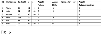
- FIG. 6 a total of six examples of common injection molding tools are listed.
- tools with 96 cavities (number 96) are known in which the cavities have a spacing of 60 mm in the column direction and a spacing of 140 mm in the row direction.
- This tool has eight rows, with twelve cavities arranged in each row.
- the cavity plate and the core plate are replaced more frequently in the known injection molding tools. This is necessary, for example, when the plates are worn. However, replacement often occurs even if the panels are still in order because the tool user may want to make other preforms or more preforms per injection cycle. In any case, then the tool halves are replaced accordingly. If the exchanged tool halves have other distances in the row and / or column direction, the removal plate and the aftertreatment plate must be replaced accordingly. This is complicated and expensive. In particular, when the user wants to produce different preforms alternately with one and the same injection mold, then not only the tool halves, but also the removal plate and the aftertreatment plate are to be exchanged at each change.
- the handling plate can be easily adapted to different injection molds with different distances between the cores and cavities in the column direction and / or row direction. This saves costs and reduces the otherwise necessary stockpiling of handling plates with different distances between the handling and / or post-treatment tools.
- the handling plate is particularly preferably designed such that the distances are variable both within the columns and / or within the rows.
- the handling plate has a base element and a plurality of carrier elements fastened or fastened to the base element, wherein each carrier element has tool holders for receiving handling and / or aftertreatment tools.
- a receptacle may be, for example, a bore to which a handling and / or aftertreatment tool can be attached.
- the support elements can each carry all disposed in a column handling and / or aftertreatment tools or correspondingly provided for this recordings.
- the basic element can be designed in several parts.
- the base element can be composed of several profile parts.
- the basic element can also be made in one piece, e.g. be formed in the form of a plate.
- At least one carrier element in a first and in a second position can be fastened to the base element.
- attachment could be provided at two different positions, such that when all the support members are secured in their first position, the distance between adjacent columns is greater or less than in a situation where all the support members are at their second position are attached.
- the carrier elements can best be fastened to the base element in each intermediate position arranged between the first and the second position. This stepless mounting option results in the greatest flexibility of the handling plate. However, care must be taken during assembly of the support elements on the base to a very accurate adjustment. Should the distances between the individual adjacent rows of handling and / or aftertreatment tools not be exactly correct, the injection mold and / or the handling plate may be damaged during operation.
- the base element could have corresponding bores with which the carrier elements can be fastened to the base element.
- the basic element could have several sets of holes, each set being marked accordingly, eg by means of a colored marking. With the help of an assignment table, the user can then select the appropriate marking for a particular tool type and fasten the carrier elements in the correspondingly marked holes of the base element.
- the tool holders of the carrier elements are designed such that a plurality of handling and / or aftertreatment tools can be attached to the carrier elements at different distances.
- the support elements are arranged relative to each other in different positions, but also arranged on a support member, the recordings or handling and / or treatment tools with different distances.
- the tool holders can be fixed in two different positions and any intermediate opposition to the support element.
- the support member could include a groove and the handling and / or post-treatment tools corresponding sliding blocks, which can be moved within the groove to secure the tools in the desired position.
- the tool holders of the carrier elements are arranged along a carrier element axis, wherein each carrier element has at least two, preferably four receiving surfaces, wherein on each receiving surface tool holders along the carrier element axis are arranged, wherein the distances between the tool holders in the Distinguish recording areas.
- a plurality of sets of tool holders are provided on a receiving surface, wherein the sets differ by different distances between adjacent tool holders. Another distance between the tool holders can then be realized by selecting a different set of tool holders. If necessary, the support element for this purpose must be displaced relative to the base element or rotated by 180 ° about an axis perpendicular to the base element.
- the carrier elements can be fastened to the base element in different positions which differ by a rotation of the carrier element about its carrier element axis, in which case in each case a different receiving surface is arranged facing away from the base element and this receiving surface has correspondingly spaced holes.
- the distance between the handling and / or aftertreatment tools can thus take place by releasing the carrier elements from the base element, by rotating the carrier elements about the carrier element axis and re-attaching the carrier elements to the base element.
- the carrier elements are designed as a hollow chamber profile with a polygonal cross section, preferably with a rectangular cross section.
- Hollow chamber profiles are inexpensive to produce and have sufficient stability. Because they have a polygonal cross-section, they can be rotated about the carrier element axis and re-attached to the base element.
- hollow chamber profiles also has the advantage that the profiles often provide a plurality of hollow chambers, so that each receiving surface is associated with a hollow chamber. This makes it possible that the hollow chambers of the hollow chamber profile can be used as Fluidzu- or -ab Installation.
- the tool holder may be formed so that it has a fluid connection with the associated hollow chamber.
- the receptacle could be formed as a bore which connects the receiving surface with the associated hollow chamber.
- At least one closure element is provided with which the fluid connection between a tool holder and the associated hollow chamber can be closed.
- the unnecessary recordings must be closed with the aid of the closure element, in order to prevent that via the hollow chamber supply or discharge fluid escapes through the unnecessary recordings.
- intermediate jumps are conceivable in which the distance between adjacent cores and cavities in the region of the intermediate jump is not twice as large, but is e.g. 1.3 times as large as the other distance between adjacent cores and cavities.
- the support element could have a receiving surface, which has no receptacles, in which, however, can be introduced if required corresponding serving as a recording holes.
- the handling and / or post-treatment tools may be receiving cavities for receiving preforms.
- the handling plate according to the invention is always moved between the open mold halves, if there are appropriate preforms to be removed.
- the handling and / or aftertreatment tools gripping tools for gripping preforms, cooling pins, which are intended to be moved into the interior of the preforms to either supply a fluid or to suck out a fluid there, and / or Embossing tools intended to be inserted inside the preform to contact the preforms and change their shape are.
- a removal plate could have three sets of receiving cavities, with a set of preforms being transferred into a set of receiving cavities each time the removal plate is driven into the opened tool. Upon subsequent insertion into the tool, the preforms are then transferred to the second set of receiving cavities and, on the third time of insertion into the tool, transferred to the third set of receiving cavities. Then the cycle repeats, i. it is handed back to the first set of receiving cavities.
- the preform held in the receiving cavity can be processed.
- cooling pins could be introduced, via which a cooling fluid can either be introduced into the preform or sucked out of it. This has the consequence that the inner surface of the preform is cooled faster.
- gripping tools could engage a second set of preforms which has remained in the post-treatment tool the longest since it must be removed next.
- the present invention further relates to an injection mold having a removal plate and / or an intermediate plate and / or a post-treatment plate, which is formed according to the handling plate according to the invention.
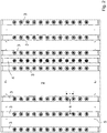
- FIG. 1 a handling plate 1 according to the invention is shown.
- This handling plate 1 has a base element 2, which is formed as a plate.
- a plurality of support elements 3 are arranged on the base element 2 .
- a plurality of positioning holes 5 are provided which can be used for positioning the support members 3 on the base member 2.
- corresponding pins can be inserted into the positioning holes, which also engage in corresponding positioning holes in the support elements 3.
- the base element 2 has different groups of holes 5, which are arranged such that the distance in the y-direction between the individual support elements 3 is different in size when using different groups of holes.
- a total of seven support elements 3 are connected to the base element 2 on a first group of bores 5. Between the third and fourth support member (seen from the left), a support member is omitted, so that the distance between the third and fourth support member (seen from the left) is twice as large as between the other support elements 3.
- Each support element 3 has in the example shown twelve gripper elements 6, which are arranged in the x-direction in a column. The distance between adjacent gripper elements 6 is the same everywhere.
- the gripper elements 6 engage in hollow chamber moldings which are held in a receiving plate.
- the gripper elements 6 are operated by compressed air, so that upon application of the gripper element with compressed air, this expands and engages the inside of the preform.
- the gripper elements could also be designed such that they can be activated by means of vacuum.
- the removal plate has more receiving cavities than preforms are made in an injection molding cycle.
- the removal plate may have twice as many receiving cavities, so that two sets of receiving cavities are provided, which are alternately loaded with preforms. This has the advantage that the preforms can remain in the extraction plate for a longer time before having to be removed again in order to make room for the next set of preforms.
- the cooling of the preform can be accelerated by a cooling pin 7, through which a cooling fluid is fed into the interior of the hollow body preform or air is sucked out of this.
- the handling plate 1 has a further carrier element 4, which in the example shown is arranged between two carrier elements 3 which carry a gripper element.
- the distance between adjacent gripper element 6 of a support element 3 and the cooling pin 7 of a support element 4 is exactly half as large as the distance between two spaced apart in the y-direction gripper elements 6 in the example shown. This has the consequence that the gripper elements in every second receiving cavity of Immerse the removal plate while immersed in the intermediate cavity of the cooling pin 7 to cool the hollow body moldings held therein.
- FIG. 1 Basically, at the in FIG. 1 embodiment shown further support elements 4 may be provided, each between or next to a support member 3, which carries gripper elements 6, be arranged. However, these have not been shown here for the sake of clarity.
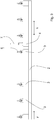
- the Figures 2 and 3 show plan views and side views of the handling plate according to the invention.
- each carrier element 3 consists of a hollow chamber profile.
- the hollow chamber profile itself consists in the embodiment shown of four hollow chambers 10, 11, 12 and 13.
- FIG. 4 has the hollow chamber profile 3 at its top a series of holes 9, which connect the upper surface of the hollow chamber profile with the hollow chamber 10. In these holes 9, the gripper elements 6 can be attached. Via the hollow chamber 10 compressed air can then be supplied to each gripper element 6 of a column.
- the support element 3 on its side surface, the in FIG. 4 pointing to the right, has bores 9 ', which connect the lateral surface with the hollow chamber 11.
- the support element can be detached from the base element 2 and rotated about a longitudinal axis, so that now the holes 9 'are at the top, i. on the side facing away from the base element 2. Now, if the gripper elements 6 are fixed in the holes 9 ', so now only nine gripper elements can be arranged within a column in contrast to the previous eleven gripper elements, the distance between the individual gripper elements 6 is larger.
- the other outer surfaces of the hollow chamber profile may also be provided with correspondingly spaced bores.
- the hollow chamber profile itself does not have to consist of a plurality of hollow chambers. However, if all holes are connected to the same hollow chamber, the unneeded holes must be closed to ensure an effective supply of compressed air.
- a plurality of sets of receptacles for example a set for receiving gripping tools and a replacement for receiving cooling pins, are arranged on a carrier element.
Landscapes
- Engineering & Computer Science (AREA)
- Manufacturing & Machinery (AREA)
- Mechanical Engineering (AREA)
- Physics & Mathematics (AREA)
- Thermal Sciences (AREA)
- Robotics (AREA)
- Moulds For Moulding Plastics Or The Like (AREA)
Applications Claiming Priority (1)
| Application Number | Priority Date | Filing Date | Title |
|---|---|---|---|
| DE102018111875.9A DE102018111875A1 (de) | 2018-05-17 | 2018-05-17 | Universalplatte |
Publications (2)
| Publication Number | Publication Date |
|---|---|
| EP3569381A1 true EP3569381A1 (fr) | 2019-11-20 |
| EP3569381B1 EP3569381B1 (fr) | 2021-02-17 |
Family
ID=66476494
Family Applications (1)
| Application Number | Title | Priority Date | Filing Date |
|---|---|---|---|
| EP19173517.4A Active EP3569381B1 (fr) | 2018-05-17 | 2019-05-09 | Plaque de manipulation |
Country Status (3)
| Country | Link |
|---|---|
| US (1) | US10899057B2 (fr) |
| EP (1) | EP3569381B1 (fr) |
| DE (1) | DE102018111875A1 (fr) |
Cited By (1)
| Publication number | Priority date | Publication date | Assignee | Title |
|---|---|---|---|---|
| WO2021209428A1 (fr) * | 2020-04-17 | 2021-10-21 | Mht Mold & Hotrunner Technology Ag | Plaque de moule d'injection optimisée et moule d'injection la comprenant |
Citations (3)
| Publication number | Priority date | Publication date | Assignee | Title |
|---|---|---|---|---|
| US20080256789A1 (en) * | 2007-04-18 | 2008-10-23 | Husky Injection Molding Systems Ltd. | System, Method and Apparatus for Configuring an End of Arm Tool in a Molding System |
| DE102010018121A1 (de) * | 2010-04-24 | 2011-10-27 | Netstal-Maschinen Ag | Spritzgießmaschine zur Herstellung einer Mehrzahl von Spritzgießteilen in einem Zyklus |
| DE102012102266A1 (de) | 2012-03-16 | 2013-09-19 | Mht Mold & Hotrunner Technology Ag | Spritzgießwerkzeugplatte sowie Spritzgießwerkzeug mit einer solchen |
Family Cites Families (25)
| Publication number | Priority date | Publication date | Assignee | Title |
|---|---|---|---|---|
| US5750162A (en) * | 1996-03-06 | 1998-05-12 | Husky Injection Molding Systems Ltd. | Turret article molding machine including blow molding station |
| US5728409A (en) * | 1996-03-06 | 1998-03-17 | Husky Injection Molding Systems Ltd. | Turret article molding machine |
| US6171541B1 (en) * | 1998-03-31 | 2001-01-09 | Husky Injection Molding Systems Ltd. | Preform post-mold cooling method and apparatus |
| US6299431B1 (en) * | 1998-07-28 | 2001-10-09 | Husky Injection Molding Systems Ltd. | Cooling apparatus for injection molding machines |
| BR9915538A (pt) * | 1998-10-22 | 2001-08-14 | Netstal Ag Maschf Giesserei | Máquina para moldagem por injeção, assim como processo para a fabricação de peças moldadas por injeção em forma de bucha, especialmente pré- formas |
| US6143225A (en) * | 1999-03-03 | 2000-11-07 | Husky Injection Molding Systems Ltd. | Turret cooling block for an index machine |
| ITPN20000006A1 (it) * | 2000-01-26 | 2001-07-26 | Sipa Spa | Impianto a torre rotante su asse orizzontale per la movimentazione dipreforme |
| ITPN20000036A1 (it) * | 2000-06-06 | 2001-12-06 | Sipa Spa | Impianto e procedimento per la movimentazione e raffreddamento di preforme plastiche |
| DE10210456A1 (de) * | 2002-03-09 | 2003-09-18 | Mht Mold & Hotrunner Tech Ag | System zum Kühlen von an einer Trägerplatte befestigten Hülsen |
| BR0310059A (pt) * | 2002-05-17 | 2005-02-15 | Husky Injection Molding | Aparelho e método de resfriamento pós-moldagem que tem movimento rotacional e transversal |
| ITRM20030460A1 (it) * | 2003-10-07 | 2005-04-08 | Sipa Societa Industrializzazione P Rogettazione A | Dispositivo e processo di iniezione di oggetti in materia plastica. |
| ITRM20030461A1 (it) * | 2003-10-07 | 2005-04-08 | Sipa Societa Industrializzazione P Rogettazione A | Dispositivo e processo di condizionamento di oggetti in materia plastica. |
| ITRM20040107A1 (it) * | 2004-03-02 | 2004-06-02 | Sipa Societa Industrializzazio | Dispositivo e metodo di condizionamento di oggetti in plastica. |
| US20070212441A1 (en) * | 2006-03-10 | 2007-09-13 | Husky Injection Molding Systems Ltd. | Molded part picker |
| US7670126B2 (en) * | 2006-05-12 | 2010-03-02 | Husky Injection Molding Systems Ltd. | Valve for controlling air flow in a molded article holder |
| ITPR20060106A1 (it) * | 2006-11-28 | 2008-05-29 | Lanfranchi Srl | Procedimento e dispositivo per prelevare, trasferire e movimentare preforme di contenitori in plastica. |
| US7854876B2 (en) * | 2007-05-25 | 2010-12-21 | Ecovision Technologies, Llc | Apparatus and methods for modular preform mold system |
| CN102497968B (zh) * | 2008-12-12 | 2014-08-27 | Mht模具及热转子技术股份公司 | 用于预制件的后处理及传递的系统 |
| EP2418068B1 (fr) * | 2010-08-10 | 2016-11-09 | Mold-Masters (2007) Limited | Système de moulage à changement rapide pour moulage par injection |
| CN104254436B (zh) * | 2012-03-12 | 2017-09-01 | 雅典娜自动化股份有限公司 | 对注塑模制品的模制后冷却 |
| BE1020911B1 (nl) * | 2012-11-30 | 2019-09-16 | Resilux | Werkwijze van overmoulding, i.h.b. bij voorvormelingen bestemd om omgevormd te worden tot behouders. |
| US8926303B2 (en) * | 2013-03-06 | 2015-01-06 | Athena Automation Ltd. | Valve assembly for an injection molding machine |
| US20170157800A1 (en) * | 2014-06-05 | 2017-06-08 | Resilux | Hollow Plastic Object, Particularly Ribbed Preform for Container and Method of Overmoulding Thereof and Device Therefor |
| CN107107416B (zh) * | 2014-10-21 | 2019-05-07 | 尼根机械有限公司 | 模制后保持装置和方法 |
| US10052804B2 (en) * | 2015-03-20 | 2018-08-21 | Athena Automation Ltd. | Cooling plate assembly for an injection molding machine |
-
2018
- 2018-05-17 DE DE102018111875.9A patent/DE102018111875A1/de not_active Withdrawn
-
2019
- 2019-05-09 EP EP19173517.4A patent/EP3569381B1/fr active Active
- 2019-05-10 US US16/408,600 patent/US10899057B2/en active Active
Patent Citations (3)
| Publication number | Priority date | Publication date | Assignee | Title |
|---|---|---|---|---|
| US20080256789A1 (en) * | 2007-04-18 | 2008-10-23 | Husky Injection Molding Systems Ltd. | System, Method and Apparatus for Configuring an End of Arm Tool in a Molding System |
| DE102010018121A1 (de) * | 2010-04-24 | 2011-10-27 | Netstal-Maschinen Ag | Spritzgießmaschine zur Herstellung einer Mehrzahl von Spritzgießteilen in einem Zyklus |
| DE102012102266A1 (de) | 2012-03-16 | 2013-09-19 | Mht Mold & Hotrunner Technology Ag | Spritzgießwerkzeugplatte sowie Spritzgießwerkzeug mit einer solchen |
Cited By (1)
| Publication number | Priority date | Publication date | Assignee | Title |
|---|---|---|---|---|
| WO2021209428A1 (fr) * | 2020-04-17 | 2021-10-21 | Mht Mold & Hotrunner Technology Ag | Plaque de moule d'injection optimisée et moule d'injection la comprenant |
Also Published As
| Publication number | Publication date |
|---|---|
| EP3569381B1 (fr) | 2021-02-17 |
| DE102018111875A1 (de) | 2019-11-21 |
| US10899057B2 (en) | 2021-01-26 |
| US20190351597A1 (en) | 2019-11-21 |
Similar Documents
| Publication | Publication Date | Title |
|---|---|---|
| EP2726265B1 (fr) | Dispositif et procédé de production de pièces moulées par injection comprenant différents composants | |
| EP0473769A1 (fr) | Dispositif de fabrication de tubes. | |
| EP0315586A1 (fr) | Moule d'injection à canal chauffé pour la fabrication de seringues à jeter et similaire | |
| DE19542102B4 (de) | Werkzeug zum Mehrkomponentenspritzgießen | |
| AT516284B1 (de) | Formwerkzeug | |
| DE102010004227B4 (de) | Verfahren und Vorrichtung zum Entformen von Spritzgusshohlkörpern mit Hinterschneidungen in der Innenkontur | |
| EP3093115B1 (fr) | Dispositif de réception et procédé d'injection | |
| DE10121691A1 (de) | Spritzgießmaschne | |
| EP3186063B1 (fr) | Système de traitement ultérieur de préformes fabriquées par moulage par injection | |
| EP2771165B1 (fr) | Procede et dispositif de fabrication de pieces moulees revetues | |
| EP3569381B1 (fr) | Plaque de manipulation | |
| EP2825361B1 (fr) | Plaque outil de moulage par injection ainsi qu'outil de moulage par injection équipé d'une telle plaque | |
| DE4243293B4 (de) | Bürstenherstellungsmaschine | |
| DE3140711C2 (de) | Mehrfach-Spritzgießform | |
| DE1679963B2 (de) | Vorrichtung zum Steuern der Öffnungsund Schließbewegung der Halsformteile und der Abstreifeinrichtung bei einer Spritz blasmaschine | |
| EP0710534B1 (fr) | Procédé et dispositif pour fabriquer des corps de brosse à partir d'au moins deux composants de matière plastique | |
| EP1954468A1 (fr) | Procede et systeme pour post-traitement de preformes | |
| DE102010018121B4 (de) | Spritzgießmaschine zur Herstellung einer Mehrzahl von Spritzgießteilen in einem Zyklus | |
| EP2691229B1 (fr) | Outil pour le moulage par injection d'objets | |
| EP0468164B1 (fr) | Procédé et dispositif pour surmouler en matière plastique des parties métalliques | |
| DE202011108698U1 (de) | Vorrichtung zur Erzeugung einer abgießbaren Markierung an einem Kern oder an einer Gießform für den Abguss eines Gießteiles | |
| DE3413201C1 (de) | Spritzblasvorrichtung | |
| DE19842092A1 (de) | Vorrichtung zur Herstellung von Spritz- und Preßteilen | |
| DE1204387B (de) | Vorrichtung zum Herstellen von Tuben aus weichem thermoplastischem Material | |
| EP2029346B1 (fr) | Dispositif de positionnement |
Legal Events
| Date | Code | Title | Description |
|---|---|---|---|
| PUAI | Public reference made under article 153(3) epc to a published international application that has entered the european phase |
Free format text: ORIGINAL CODE: 0009012 |
|
| STAA | Information on the status of an ep patent application or granted ep patent |
Free format text: STATUS: THE APPLICATION HAS BEEN PUBLISHED |
|
| AK | Designated contracting states |
Kind code of ref document: A1 Designated state(s): AL AT BE BG CH CY CZ DE DK EE ES FI FR GB GR HR HU IE IS IT LI LT LU LV MC MK MT NL NO PL PT RO RS SE SI SK SM TR |
|
| AX | Request for extension of the european patent |
Extension state: BA ME |
|
| STAA | Information on the status of an ep patent application or granted ep patent |
Free format text: STATUS: REQUEST FOR EXAMINATION WAS MADE |
|
| 17P | Request for examination filed |
Effective date: 20200422 |
|
| RBV | Designated contracting states (corrected) |
Designated state(s): AL AT BE BG CH CY CZ DE DK EE ES FI FR GB GR HR HU IE IS IT LI LT LU LV MC MK MT NL NO PL PT RO RS SE SI SK SM TR |
|
| GRAP | Despatch of communication of intention to grant a patent |
Free format text: ORIGINAL CODE: EPIDOSNIGR1 |
|
| STAA | Information on the status of an ep patent application or granted ep patent |
Free format text: STATUS: GRANT OF PATENT IS INTENDED |
|
| RIC1 | Information provided on ipc code assigned before grant |
Ipc: B29K 105/00 20060101ALN20200908BHEP Ipc: B29C 45/42 20060101AFI20200908BHEP Ipc: B29C 45/72 20060101ALI20200908BHEP Ipc: B29C 49/64 20060101ALI20200908BHEP |
|
| INTG | Intention to grant announced |
Effective date: 20201006 |
|
| GRAS | Grant fee paid |
Free format text: ORIGINAL CODE: EPIDOSNIGR3 |
|
| GRAA | (expected) grant |
Free format text: ORIGINAL CODE: 0009210 |
|
| STAA | Information on the status of an ep patent application or granted ep patent |
Free format text: STATUS: THE PATENT HAS BEEN GRANTED |
|
| AK | Designated contracting states |
Kind code of ref document: B1 Designated state(s): AL AT BE BG CH CY CZ DE DK EE ES FI FR GB GR HR HU IE IS IT LI LT LU LV MC MK MT NL NO PL PT RO RS SE SI SK SM TR |
|
| REG | Reference to a national code |
Ref country code: GB Ref legal event code: FG4D Free format text: NOT ENGLISH |
|
| REG | Reference to a national code |
Ref country code: CH Ref legal event code: EP |
|
| REG | Reference to a national code |
Ref country code: DE Ref legal event code: R096 Ref document number: 502019000799 Country of ref document: DE |
|
| REG | Reference to a national code |
Ref country code: CH Ref legal event code: NV Representative=s name: ISLER AND PEDRAZZINI AG, CH Ref country code: AT Ref legal event code: REF Ref document number: 1360903 Country of ref document: AT Kind code of ref document: T Effective date: 20210315 |
|
| REG | Reference to a national code |
Ref country code: IE Ref legal event code: FG4D Free format text: LANGUAGE OF EP DOCUMENT: GERMAN |
|
| REG | Reference to a national code |
Ref country code: LT Ref legal event code: MG9D |
|
| REG | Reference to a national code |
Ref country code: NL Ref legal event code: MP Effective date: 20210217 |
|
| PG25 | Lapsed in a contracting state [announced via postgrant information from national office to epo] |
Ref country code: BG Free format text: LAPSE BECAUSE OF FAILURE TO SUBMIT A TRANSLATION OF THE DESCRIPTION OR TO PAY THE FEE WITHIN THE PRESCRIBED TIME-LIMIT Effective date: 20210517 Ref country code: HR Free format text: LAPSE BECAUSE OF FAILURE TO SUBMIT A TRANSLATION OF THE DESCRIPTION OR TO PAY THE FEE WITHIN THE PRESCRIBED TIME-LIMIT Effective date: 20210217 Ref country code: FI Free format text: LAPSE BECAUSE OF FAILURE TO SUBMIT A TRANSLATION OF THE DESCRIPTION OR TO PAY THE FEE WITHIN THE PRESCRIBED TIME-LIMIT Effective date: 20210217 Ref country code: GR Free format text: LAPSE BECAUSE OF FAILURE TO SUBMIT A TRANSLATION OF THE DESCRIPTION OR TO PAY THE FEE WITHIN THE PRESCRIBED TIME-LIMIT Effective date: 20210518 Ref country code: LT Free format text: LAPSE BECAUSE OF FAILURE TO SUBMIT A TRANSLATION OF THE DESCRIPTION OR TO PAY THE FEE WITHIN THE PRESCRIBED TIME-LIMIT Effective date: 20210217 Ref country code: NO Free format text: LAPSE BECAUSE OF FAILURE TO SUBMIT A TRANSLATION OF THE DESCRIPTION OR TO PAY THE FEE WITHIN THE PRESCRIBED TIME-LIMIT Effective date: 20210517 Ref country code: PT Free format text: LAPSE BECAUSE OF FAILURE TO SUBMIT A TRANSLATION OF THE DESCRIPTION OR TO PAY THE FEE WITHIN THE PRESCRIBED TIME-LIMIT Effective date: 20210617 |
|
| PG25 | Lapsed in a contracting state [announced via postgrant information from national office to epo] |
Ref country code: SE Free format text: LAPSE BECAUSE OF FAILURE TO SUBMIT A TRANSLATION OF THE DESCRIPTION OR TO PAY THE FEE WITHIN THE PRESCRIBED TIME-LIMIT Effective date: 20210217 Ref country code: RS Free format text: LAPSE BECAUSE OF FAILURE TO SUBMIT A TRANSLATION OF THE DESCRIPTION OR TO PAY THE FEE WITHIN THE PRESCRIBED TIME-LIMIT Effective date: 20210217 Ref country code: LV Free format text: LAPSE BECAUSE OF FAILURE TO SUBMIT A TRANSLATION OF THE DESCRIPTION OR TO PAY THE FEE WITHIN THE PRESCRIBED TIME-LIMIT Effective date: 20210217 Ref country code: NL Free format text: LAPSE BECAUSE OF FAILURE TO SUBMIT A TRANSLATION OF THE DESCRIPTION OR TO PAY THE FEE WITHIN THE PRESCRIBED TIME-LIMIT Effective date: 20210217 Ref country code: PL Free format text: LAPSE BECAUSE OF FAILURE TO SUBMIT A TRANSLATION OF THE DESCRIPTION OR TO PAY THE FEE WITHIN THE PRESCRIBED TIME-LIMIT Effective date: 20210217 |
|
| PG25 | Lapsed in a contracting state [announced via postgrant information from national office to epo] |
Ref country code: IS Free format text: LAPSE BECAUSE OF FAILURE TO SUBMIT A TRANSLATION OF THE DESCRIPTION OR TO PAY THE FEE WITHIN THE PRESCRIBED TIME-LIMIT Effective date: 20210617 |
|
| PG25 | Lapsed in a contracting state [announced via postgrant information from national office to epo] |
Ref country code: SM Free format text: LAPSE BECAUSE OF FAILURE TO SUBMIT A TRANSLATION OF THE DESCRIPTION OR TO PAY THE FEE WITHIN THE PRESCRIBED TIME-LIMIT Effective date: 20210217 Ref country code: EE Free format text: LAPSE BECAUSE OF FAILURE TO SUBMIT A TRANSLATION OF THE DESCRIPTION OR TO PAY THE FEE WITHIN THE PRESCRIBED TIME-LIMIT Effective date: 20210217 Ref country code: CZ Free format text: LAPSE BECAUSE OF FAILURE TO SUBMIT A TRANSLATION OF THE DESCRIPTION OR TO PAY THE FEE WITHIN THE PRESCRIBED TIME-LIMIT Effective date: 20210217 |
|
| REG | Reference to a national code |
Ref country code: DE Ref legal event code: R097 Ref document number: 502019000799 Country of ref document: DE |
|
| PG25 | Lapsed in a contracting state [announced via postgrant information from national office to epo] |
Ref country code: RO Free format text: LAPSE BECAUSE OF FAILURE TO SUBMIT A TRANSLATION OF THE DESCRIPTION OR TO PAY THE FEE WITHIN THE PRESCRIBED TIME-LIMIT Effective date: 20210217 Ref country code: SK Free format text: LAPSE BECAUSE OF FAILURE TO SUBMIT A TRANSLATION OF THE DESCRIPTION OR TO PAY THE FEE WITHIN THE PRESCRIBED TIME-LIMIT Effective date: 20210217 Ref country code: DK Free format text: LAPSE BECAUSE OF FAILURE TO SUBMIT A TRANSLATION OF THE DESCRIPTION OR TO PAY THE FEE WITHIN THE PRESCRIBED TIME-LIMIT Effective date: 20210217 |
|
| PLBE | No opposition filed within time limit |
Free format text: ORIGINAL CODE: 0009261 |
|
| STAA | Information on the status of an ep patent application or granted ep patent |
Free format text: STATUS: NO OPPOSITION FILED WITHIN TIME LIMIT |
|
| 26N | No opposition filed |
Effective date: 20211118 |
|
| PG25 | Lapsed in a contracting state [announced via postgrant information from national office to epo] |
Ref country code: ES Free format text: LAPSE BECAUSE OF FAILURE TO SUBMIT A TRANSLATION OF THE DESCRIPTION OR TO PAY THE FEE WITHIN THE PRESCRIBED TIME-LIMIT Effective date: 20210217 Ref country code: AL Free format text: LAPSE BECAUSE OF FAILURE TO SUBMIT A TRANSLATION OF THE DESCRIPTION OR TO PAY THE FEE WITHIN THE PRESCRIBED TIME-LIMIT Effective date: 20210217 Ref country code: LU Free format text: LAPSE BECAUSE OF NON-PAYMENT OF DUE FEES Effective date: 20210509 Ref country code: MC Free format text: LAPSE BECAUSE OF FAILURE TO SUBMIT A TRANSLATION OF THE DESCRIPTION OR TO PAY THE FEE WITHIN THE PRESCRIBED TIME-LIMIT Effective date: 20210217 |
|
| REG | Reference to a national code |
Ref country code: BE Ref legal event code: MM Effective date: 20210531 |
|
| PG25 | Lapsed in a contracting state [announced via postgrant information from national office to epo] |
Ref country code: SI Free format text: LAPSE BECAUSE OF FAILURE TO SUBMIT A TRANSLATION OF THE DESCRIPTION OR TO PAY THE FEE WITHIN THE PRESCRIBED TIME-LIMIT Effective date: 20210217 |
|
| PG25 | Lapsed in a contracting state [announced via postgrant information from national office to epo] |
Ref country code: IE Free format text: LAPSE BECAUSE OF NON-PAYMENT OF DUE FEES Effective date: 20210509 |
|
| PG25 | Lapsed in a contracting state [announced via postgrant information from national office to epo] |
Ref country code: IS Free format text: LAPSE BECAUSE OF FAILURE TO SUBMIT A TRANSLATION OF THE DESCRIPTION OR TO PAY THE FEE WITHIN THE PRESCRIBED TIME-LIMIT Effective date: 20210617 Ref country code: FR Free format text: LAPSE BECAUSE OF NON-PAYMENT OF DUE FEES Effective date: 20210531 |
|
| PG25 | Lapsed in a contracting state [announced via postgrant information from national office to epo] |
Ref country code: BE Free format text: LAPSE BECAUSE OF NON-PAYMENT OF DUE FEES Effective date: 20210531 |
|
| PG25 | Lapsed in a contracting state [announced via postgrant information from national office to epo] |
Ref country code: CY Free format text: LAPSE BECAUSE OF FAILURE TO SUBMIT A TRANSLATION OF THE DESCRIPTION OR TO PAY THE FEE WITHIN THE PRESCRIBED TIME-LIMIT Effective date: 20210217 |
|
| PG25 | Lapsed in a contracting state [announced via postgrant information from national office to epo] |
Ref country code: HU Free format text: LAPSE BECAUSE OF FAILURE TO SUBMIT A TRANSLATION OF THE DESCRIPTION OR TO PAY THE FEE WITHIN THE PRESCRIBED TIME-LIMIT; INVALID AB INITIO Effective date: 20190509 |
|
| PGFP | Annual fee paid to national office [announced via postgrant information from national office to epo] |
Ref country code: IT Payment date: 20230526 Year of fee payment: 5 Ref country code: DE Payment date: 20230523 Year of fee payment: 5 Ref country code: CH Payment date: 20230605 Year of fee payment: 5 |
|
| GBPC | Gb: european patent ceased through non-payment of renewal fee |
Effective date: 20230509 |
|
| PG25 | Lapsed in a contracting state [announced via postgrant information from national office to epo] |
Ref country code: MK Free format text: LAPSE BECAUSE OF FAILURE TO SUBMIT A TRANSLATION OF THE DESCRIPTION OR TO PAY THE FEE WITHIN THE PRESCRIBED TIME-LIMIT Effective date: 20210217 Ref country code: GB Free format text: LAPSE BECAUSE OF NON-PAYMENT OF DUE FEES Effective date: 20230509 |