EP3569337B1 - Werkzeug- oder werkstückaufnahme und set aus werkzeugmaschine und werkzeug- oder werkstückaufnahme - Google Patents
Werkzeug- oder werkstückaufnahme und set aus werkzeugmaschine und werkzeug- oder werkstückaufnahme Download PDFInfo
- Publication number
- EP3569337B1 EP3569337B1 EP18172995.5A EP18172995A EP3569337B1 EP 3569337 B1 EP3569337 B1 EP 3569337B1 EP 18172995 A EP18172995 A EP 18172995A EP 3569337 B1 EP3569337 B1 EP 3569337B1
- Authority
- EP
- European Patent Office
- Prior art keywords
- tool
- workpiece
- holder
- workpiece holder
- section
- Prior art date
- Legal status (The legal status is an assumption and is not a legal conclusion. Google has not performed a legal analysis and makes no representation as to the accuracy of the status listed.)
- Active
Links
Images


Classifications
-
- B—PERFORMING OPERATIONS; TRANSPORTING
- B23—MACHINE TOOLS; METAL-WORKING NOT OTHERWISE PROVIDED FOR
- B23Q—DETAILS, COMPONENTS, OR ACCESSORIES FOR MACHINE TOOLS, e.g. ARRANGEMENTS FOR COPYING OR CONTROLLING; MACHINE TOOLS IN GENERAL CHARACTERISED BY THE CONSTRUCTION OF PARTICULAR DETAILS OR COMPONENTS; COMBINATIONS OR ASSOCIATIONS OF METAL-WORKING MACHINES, NOT DIRECTED TO A PARTICULAR RESULT
- B23Q3/00—Devices holding, supporting, or positioning work or tools, of a kind normally removable from the machine
- B23Q3/02—Devices holding, supporting, or positioning work or tools, of a kind normally removable from the machine for mounting on a work-table, tool-slide, or analogous part
- B23Q3/10—Auxiliary devices, e.g. bolsters, extension members
- B23Q3/105—Auxiliary supporting devices independent of the machine tool
-
- B—PERFORMING OPERATIONS; TRANSPORTING
- B23—MACHINE TOOLS; METAL-WORKING NOT OTHERWISE PROVIDED FOR
- B23B—TURNING; BORING
- B23B31/00—Chucks; Expansion mandrels; Adaptations thereof for remote control
- B23B31/005—Cylindrical shanks of tools
-
- B—PERFORMING OPERATIONS; TRANSPORTING
- B23—MACHINE TOOLS; METAL-WORKING NOT OTHERWISE PROVIDED FOR
- B23B—TURNING; BORING
- B23B31/00—Chucks; Expansion mandrels; Adaptations thereof for remote control
- B23B31/006—Conical shanks of tools
-
- B—PERFORMING OPERATIONS; TRANSPORTING
- B23—MACHINE TOOLS; METAL-WORKING NOT OTHERWISE PROVIDED FOR
- B23Q—DETAILS, COMPONENTS, OR ACCESSORIES FOR MACHINE TOOLS, e.g. ARRANGEMENTS FOR COPYING OR CONTROLLING; MACHINE TOOLS IN GENERAL CHARACTERISED BY THE CONSTRUCTION OF PARTICULAR DETAILS OR COMPONENTS; COMBINATIONS OR ASSOCIATIONS OF METAL-WORKING MACHINES, NOT DIRECTED TO A PARTICULAR RESULT
- B23Q1/00—Members which are comprised in the general build-up of a form of machine, particularly relatively large fixed members
- B23Q1/25—Movable or adjustable work or tool supports
- B23Q1/44—Movable or adjustable work or tool supports using particular mechanisms
-
- B—PERFORMING OPERATIONS; TRANSPORTING
- B23—MACHINE TOOLS; METAL-WORKING NOT OTHERWISE PROVIDED FOR
- B23Q—DETAILS, COMPONENTS, OR ACCESSORIES FOR MACHINE TOOLS, e.g. ARRANGEMENTS FOR COPYING OR CONTROLLING; MACHINE TOOLS IN GENERAL CHARACTERISED BY THE CONSTRUCTION OF PARTICULAR DETAILS OR COMPONENTS; COMBINATIONS OR ASSOCIATIONS OF METAL-WORKING MACHINES, NOT DIRECTED TO A PARTICULAR RESULT
- B23Q1/00—Members which are comprised in the general build-up of a form of machine, particularly relatively large fixed members
- B23Q1/72—Auxiliary arrangements; Interconnections between auxiliary tables and movable machine elements
-
- B—PERFORMING OPERATIONS; TRANSPORTING
- B23—MACHINE TOOLS; METAL-WORKING NOT OTHERWISE PROVIDED FOR
- B23Q—DETAILS, COMPONENTS, OR ACCESSORIES FOR MACHINE TOOLS, e.g. ARRANGEMENTS FOR COPYING OR CONTROLLING; MACHINE TOOLS IN GENERAL CHARACTERISED BY THE CONSTRUCTION OF PARTICULAR DETAILS OR COMPONENTS; COMBINATIONS OR ASSOCIATIONS OF METAL-WORKING MACHINES, NOT DIRECTED TO A PARTICULAR RESULT
- B23Q3/00—Devices holding, supporting, or positioning work or tools, of a kind normally removable from the machine
- B23Q3/02—Devices holding, supporting, or positioning work or tools, of a kind normally removable from the machine for mounting on a work-table, tool-slide, or analogous part
- B23Q3/06—Work-clamping means
-
- B—PERFORMING OPERATIONS; TRANSPORTING
- B23—MACHINE TOOLS; METAL-WORKING NOT OTHERWISE PROVIDED FOR
- B23Q—DETAILS, COMPONENTS, OR ACCESSORIES FOR MACHINE TOOLS, e.g. ARRANGEMENTS FOR COPYING OR CONTROLLING; MACHINE TOOLS IN GENERAL CHARACTERISED BY THE CONSTRUCTION OF PARTICULAR DETAILS OR COMPONENTS; COMBINATIONS OR ASSOCIATIONS OF METAL-WORKING MACHINES, NOT DIRECTED TO A PARTICULAR RESULT
- B23Q3/00—Devices holding, supporting, or positioning work or tools, of a kind normally removable from the machine
- B23Q3/12—Devices holding, supporting, or positioning work or tools, of a kind normally removable from the machine for securing to a spindle in general
-
- B—PERFORMING OPERATIONS; TRANSPORTING
- B23—MACHINE TOOLS; METAL-WORKING NOT OTHERWISE PROVIDED FOR
- B23B—TURNING; BORING
- B23B2231/00—Details of chucks, toolholder shanks or tool shanks
- B23B2231/04—Adapters
Definitions
- Machine tools are being operated in an increasingly automated manner. This means in particular that the tool change during operation of such a machine tool is also carried out partially or fully automatically. It is common practice to provide the various tools with a tool holder and to connect the tool to the corresponding spindle of the machine tool via the tool holder. The tool holder therefore forms the interface between the tool and the machine.
- tool or workpiece holder is used below, although in principle every tool holder is also a workpiece holder or becomes a workpiece holder when the clamping device in which the tool is held in a tool holder is used to hold a workpiece. In structural terms, tool and workpiece holders do not necessarily differ from one another.
- the standardized section of the tool or workpiece holder that is connected to the spindle is referred to in this description as the "coupling section”, and the standardized section of the spindle that interacts with this coupling section of the tool or workpiece holder is referred to as the tool interface.
- the tool interfaces are always designed by the manufacturer so that they interact with standardized coupling sections of tool or workpiece holders as intended, but may be modified to suit the manufacturer.
- a well-known approach to avoid this is to provide interface adapters for coupling tool or workpiece holders according to a first standard to the spindle of a machine tool for tool or workpiece holders according to a second standard.
- Such an interface adapter thus represents, in a sense, a component with which the spindle of the machine tool is extended, wherein the connection to the spindle is established via a section in the machine-side end region of the interface adapter that corresponds to the standard for the tool or workpiece holder for which the machine tool is designed, and wherein the interface adapter has, at its tool-side end region, a holder for the coupling section of the tool or workpiece holder that corresponds to another standard.
- the object of the invention is therefore to provide a tool or workpiece holder which, even without an interface adapter, is suitable for use with tool interfaces of spindles of machine tools designed for interaction with tool or workpiece holders subject to different standards.
- the tool or workpiece holder according to the invention for coupling a tool or workpiece to a drive spindle of a machine tool has a tool or workpiece holder section on which a clamping device for holding the tool or workpiece is arranged and a coupling section for coupling to a tool interface of the drive spindle of the machine tool. Furthermore, the coupling section is designed in such a way that it is suitable for coupling both to a tool interface for holding tool or workpiece holders according to a first standard and to a tool interface for holding tool or workpiece holders according to a second standard.
- a tool interface is to be regarded as suitable for receiving a tool or workpiece holder of a given standard if it can interact with such a tool holder that is subject to the given standard in such a way that tools received in the tool holder can be used by the machine tool to machine workpieces. or workpieces held in the workpiece holder can be machined by the machine tool with tools.
- This understanding of the term means in particular that the tool interface - particularly manufacturer-specific or application-specific - can be modified in such a way that sections of the tool interface no longer contribute to the interaction of the tool interface with a standard-compliant tool or workpiece holder.
- a first concrete solution according to the invention for realizing such a coupling section consists in that the coupling section has an adapter ring which can be fixed to the tool or workpiece holder in two different orientations, so that the tool or workpiece holder can be coupled to the tool interface for receiving tool or workpiece holders in accordance with the first standard in one orientation of the adapter ring and can be coupled to the tool interface for receiving tool or workpiece holders in accordance with the second standard in the second orientation of the adapter ring.
- ring in the designation "adapter ring” is intended to represent a geometric restriction only insofar as it specifies that the geometric structure of the adapter ring can be described by a 360° rotation of a surface around an axis that lies in the same plane as the surface but does not intersect the surface.
- a disk-shaped structure can therefore also be understood as an adapter ring.
- What is particularly important for coupling the adapter ring to a tool interface is the shape of the sections of the contour of the surface on the side facing away from this axis, i.e. its outer contour.
- Such an adapter ring can therefore be constructed in such a way that above a plane in which its radii lie, its outer contour is designed in such a way that it can interact with a tool interface for receiving tool or workpiece holders of a first standard, while below this plane its outer contour is designed in such a way that it can interact with a tool interface for receiving tool or workpiece holders of a second standard.
- top and bottom sides can extend to different distances in the axial direction, i.e. perpendicular to the said plane, in order to meet the requirements of the different tool interfaces with which they are intended to interact.
- the adapter ring can be fixed, for example, with screws that penetrate the adapter ring material essentially in a direction perpendicular to the plane in which the radii of the ring lie and fasten it to the tool or workpiece holder.
- the adapter ring is sectionally - in particular with a section of the upper or lower side relative to the plane in which the radii of the adapter ring lie - is accommodated in an annular groove in the tool or workpiece holder. If this is designed without play, this enables highly precise positioning of the adapter ring. On the other hand, an annular groove with play in conjunction with adjusting devices allows tolerance compensation, which may also be desirable depending on the application.
- an alternative concrete solution according to the invention for realizing such a first coupling section consists in that the coupling section has a first section which allows a coupling to a tool interface for receiving tool or workpiece holders in accordance with the first standard and a second section which is indirectly connected, i.e. via an intermediate region, to the first section - in particular in the axial direction of the tool or workpiece holder, which usually coincides with the course of the axis of rotation of the tool or workpiece received in the tool or workpiece holder when it is used - or directly adjoins it, which allows a coupling to a tool interface for receiving tool or workpiece holders in accordance with the second standard.
- such a tool or workpiece holder can be implemented for applications in which the tool interface for receiving tool or workpiece holders according to the first standard is a tool interface suitable for steep taper tool holders and the tool interface for receiving tool or workpiece holders according to the second standard is a tool interface suitable for hollow shank taper tool holders.
- the section intended for interaction with the tool interface suitable for steep taper tool holders is further away from the clamping device than the section intended for interaction with the tool interface suitable for hollow shank taper tool holders.
- the tool or workpiece holder has a stop that defines an insertion depth of the tool or workpiece holder in the tool interface.
- This can be, for example, the front face of a collar that is arranged in such a way that this front face interacts with a front face of the spindle at the desired insertion depth.
- the set according to the invention comprises a machine tool with at least one spindle, which has a tool interface for receiving tool or workpiece holders according to a first standard and at least one tool or workpiece holder according to the invention.
- the tool interface has at least one modified section so that in the modified section(s) it does not interact with a tool or workpiece holder according to the first standard, through the interaction of this tool or workpiece holder with the other sections
- a modified tool interface still guarantees the safe and intended use of the tool or workpiece holder complying with the first standard and the tool arranged therein when using the machine tool.
- a tool interface for a tool holder according to the SK50 standard can have an annular recess with a diameter of 70 mm in its modified front end section without losing functionality for use with tool holders with the SK50 standard.
- Figure 1 shows a first embodiment of a tool or workpiece holder 100 for coupling a Figure 1 not shown tool to a also in Figure 1 not shown drive spindle of a machine tool.
- the tool or workpiece holder 100 has a tool or workpiece holder section 110 on the tool side, i.e. on the side on which the tool is held, which in turn has a clamping device 111, which in this example is designed as a conventional hydraulic expansion chuck well known in the art and therefore does not require any further description.
- the tool or workpiece holder 100 has a coupling section 120 on the machine side, i.e. on the side on which the interaction with the drive spindle or its tool interface is established, for coupling to a Figure 1 not shown tool interface of a drive spindle of a machine tool, which in particular has a collar 121, an adapter ring 122 and a cylindrical extension 123.
- the adapter ring 122 is designed such that its outer contour 122a is on one side of a plane E in which the radii of the adapter ring 122 lie and which in the Figure 1 approximately coincides with the machine-side surface of the collar 121, lies -in the Figure 1
- the orientation of the adapter ring 122 shown to the left of the plane E- is suitable for inclusion in a tool interface according to the SK50 standard.
- the outer contour 122b which is on the other side of the plane E in which the radii of the adapter ring 122 lie and which is in the Figure 1 approximately coincides with the machine-side surface of the collar 121, lies -in the Figure 1 reproduced orientation of the adapter ring 122 to the right of the plane E- is However, it is suitable for use in a tool interface according to the HSK80 standard.
- An annular groove 124 is recessed into the machine-side surface of the collar 121, which forms a stop 126, in which the adapter ring 122 is partially received, in particular with the outer contour 122b, and fastened with screws 125, so that only the outer contour 122a is available for interaction with a tool interface.
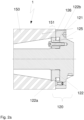
- the Figure 2a shows a section of a set 1 of a machine tool and a tool or workpiece holder 100 according to Figure 1 , which illustrates the interaction of the tool or workpiece holder 100 with a tool interface for tool holders according to the SK-50 standard, in a state of the set in which the tool or workpiece holder is arranged on the machine tool.
- This section covers the interaction area between the end section of a tool interface 150 of a spindle of a machine tool facing the tool and the coupling section 120 of the tool or workpiece holder 100.
- the tool interface 150 shown is designed to accommodate tool holders in accordance with the SK-50 standard, but has a modified section 151 in its end area facing the tool, which is designed with an annular recess with a diameter of 70 mm.
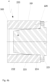
- the Figure 2b shows a section of a set 2 of a machine tool and a tool or workpiece holder 100 according to Figure 1 , which illustrates the interaction of the tool or workpiece holder 100 with a tool interface for tool holders according to the SK-50 standard, in a state of the set in which the tool or workpiece holder is arranged on the machine tool.
- This section covers the interaction area between the end section of a tool interface 160 of a spindle of a machine tool other than that of the set, which is facing the tool.
- the tool interface 160 shown is designed for the reception of tool holders in accordance with the HSK-80 standard
- Figure 3 shows a second embodiment of a tool or workpiece holder 200 for coupling a Figure 3 not shown tool to a also in Figure 3 not shown drive spindle of a machine tool.
- the tool or workpiece holder 200 has a tool or workpiece holder section 210 on the tool side, i.e. on the side on which the tool is held.
- the tool or workpiece holder section 210 in turn has a conventional collet chuck as clamping means 211 with a collet 212 that becomes larger towards the tool side, which is held in a guide 213 that tapers conically in sections and is clamped to the guide 213 by a plate spring stack 214 in such a way that the collet 212 is drawn into the conical section 213a of the guide and is thus pre-tensioned in its closed position.
- a punch 215 is provided to overcome this pre-tension, for example when inserting a tool.
- the tool or workpiece holder 200 has on the machine side, i.e. on the side on which the interaction with the drive spindle or its tool interface is established, a coupling section 220 for coupling to a Figure 1 not shown tool interface of a drive spindle of a machine tool.
- the coupling section 220 has a first section 222, which allows a coupling to a tool interface for receiving tool or workpiece holders according to a first standard, here the SK50 standard, as well as a second section 224, which adjoins the first section 222 indirectly, i.e.
- the first section 222 therefore corresponds to a section of an SK50 taper, while the second section 224 corresponds to a section of an HSK80 taper.
- the Figure 4a shows a section of a set 3 of a machine tool and a tool or workpiece holder 200 according to Figure 3 , which illustrates the interaction of the tool or workpiece holder 200 with a tool interface for tool holders according to the SK-50 standard, in a state of the set in which the tool or workpiece holder is arranged on the machine tool.
- This section covers the interaction area between the end section of a tool interface 250 of a spindle of a machine tool facing the tool and the coupling section 220 of the tool or workpiece holder 200.
- the tool interface 250 shown is designed to accommodate tool holders in accordance with the SK-50 standard, but has a modified section 251 in its end area facing the tool, which is designed with an annular recess with a diameter of 70 mm.
- the Figure 4b shows a section of a set 4 consisting of a machine tool and a tool or workpiece holder 200 according to Figure 3 , which illustrates the interaction of the tool or workpiece holder 200 with a tool interface for tool holders according to the SK-50 standard, in a state of the set in which the tool or workpiece holder is arranged on the machine tool.
- This section covers the interaction area between the end section of a tool interface 260 of a spindle of a machine tool other than that of the set, which is facing the tool.
- Figure 4a or another spindle of the same machine tool as that of the set of Figure 4a and the coupling section 220 of the tool or workpiece holder 200.
- the tool interface 260 shown is designed for the reception of tool holders in accordance with the HSK-80 standard
Landscapes
- Engineering & Computer Science (AREA)
- Mechanical Engineering (AREA)
- Jigs For Machine Tools (AREA)
Priority Applications (4)
| Application Number | Priority Date | Filing Date | Title |
|---|---|---|---|
| ES18172995T ES2987590T3 (es) | 2018-05-17 | 2018-05-17 | Portaherramientas o portapiezas y kit compuesto por una máquina herramienta y un portaherramientas o portapiezas |
| PL18172995.5T PL3569337T3 (pl) | 2018-05-17 | 2018-05-17 | Uchwyt narzędzia lub uchwyt przedmiotu obrabianego i zestaw składający się z obrabiarki oraz uchwytu narzędzia lub uchwytu przedmiotu obrabianego |
| EP18172995.5A EP3569337B1 (de) | 2018-05-17 | 2018-05-17 | Werkzeug- oder werkstückaufnahme und set aus werkzeugmaschine und werkzeug- oder werkstückaufnahme |
| US16/413,099 US11135692B2 (en) | 2018-05-17 | 2019-05-15 | Tool holder or workpiece holder and set comprising machine tool and tool holder or workpiece holder |
Applications Claiming Priority (1)
| Application Number | Priority Date | Filing Date | Title |
|---|---|---|---|
| EP18172995.5A EP3569337B1 (de) | 2018-05-17 | 2018-05-17 | Werkzeug- oder werkstückaufnahme und set aus werkzeugmaschine und werkzeug- oder werkstückaufnahme |
Publications (2)
| Publication Number | Publication Date |
|---|---|
| EP3569337A1 EP3569337A1 (de) | 2019-11-20 |
| EP3569337B1 true EP3569337B1 (de) | 2024-04-10 |
Family
ID=62200305
Family Applications (1)
| Application Number | Title | Priority Date | Filing Date |
|---|---|---|---|
| EP18172995.5A Active EP3569337B1 (de) | 2018-05-17 | 2018-05-17 | Werkzeug- oder werkstückaufnahme und set aus werkzeugmaschine und werkzeug- oder werkstückaufnahme |
Country Status (4)
| Country | Link |
|---|---|
| US (1) | US11135692B2 (pl) |
| EP (1) | EP3569337B1 (pl) |
| ES (1) | ES2987590T3 (pl) |
| PL (1) | PL3569337T3 (pl) |
Families Citing this family (2)
| Publication number | Priority date | Publication date | Assignee | Title |
|---|---|---|---|---|
| DE202019107127U1 (de) * | 2019-12-19 | 2021-03-22 | Ferrobotics Compliant Robot Technology Gmbh | Wellenkupplung für Werkzeugmaschinen |
| TWI768768B (zh) * | 2021-03-16 | 2022-06-21 | 德大機械股份有限公司 | 刀庫刀把保持裝置 |
Citations (1)
| Publication number | Priority date | Publication date | Assignee | Title |
|---|---|---|---|---|
| US6409439B1 (en) * | 1999-10-12 | 2002-06-25 | Seco Tools Ab | Convertible tool holder for a machine tool |
Family Cites Families (4)
| Publication number | Priority date | Publication date | Assignee | Title |
|---|---|---|---|---|
| CH484713A (de) * | 1968-01-12 | 1970-01-31 | Baechtold Fritz | Fräsdorn |
| EP0443102A1 (de) * | 1990-02-22 | 1991-08-28 | Walter Ag | Aufnahmedorn mit Spindelanlage für Werkzeuge |
| CH686120A5 (de) * | 1992-09-21 | 1996-01-15 | Hans Imfeld Elektroapparatebau | Konischer Werkzeugschaft fur mehrere Einspannmoglichkeiten. |
| FR2819742B1 (fr) * | 2001-01-25 | 2003-05-09 | Chartreuse Prec | Dispositif de montage d'un porte outil dans une broche d'une machine-outil |
-
2018
- 2018-05-17 PL PL18172995.5T patent/PL3569337T3/pl unknown
- 2018-05-17 EP EP18172995.5A patent/EP3569337B1/de active Active
- 2018-05-17 ES ES18172995T patent/ES2987590T3/es active Active
-
2019
- 2019-05-15 US US16/413,099 patent/US11135692B2/en active Active
Patent Citations (1)
| Publication number | Priority date | Publication date | Assignee | Title |
|---|---|---|---|---|
| US6409439B1 (en) * | 1999-10-12 | 2002-06-25 | Seco Tools Ab | Convertible tool holder for a machine tool |
Also Published As
| Publication number | Publication date |
|---|---|
| US11135692B2 (en) | 2021-10-05 |
| US20190351518A1 (en) | 2019-11-21 |
| EP3569337A1 (de) | 2019-11-20 |
| PL3569337T3 (pl) | 2024-07-01 |
| ES2987590T3 (es) | 2024-11-15 |
Similar Documents
| Publication | Publication Date | Title |
|---|---|---|
| EP0216796B1 (de) | Werkzeughalter od.dgl. | |
| EP0141451B1 (de) | Werkzeugaufnahmevorrichtung und Werkzeugträger | |
| DE69714781T2 (de) | Hydromechanisches futter | |
| EP1932607A1 (de) | Werkstückträger zum positionsgenauen Festlegen an einem Spannfutter sowie Spannvorrichtung mit einem Spannfutter und einem positionsgenau daran festspannbaren Werkstückträger | |
| EP2134490A1 (de) | Werkzeughalter | |
| DE112008000350T5 (de) | Werkzeug mit Schrumpfpassung und mit mechanischem Halteteil und Verfahren zum Montieren eines Werkzeuges an einem Werkzeughalter | |
| EP1654091B1 (de) | Werkzeugkupplung | |
| WO2011015259A1 (de) | Werkzeugträger mit auswechselbaren werkzeughaltern und werkzeughalter | |
| DE69809439T2 (de) | Werkzeughalter | |
| EP0364821A2 (de) | Werkzeugadapter für eine Werkzeugmaschinenspindel | |
| EP3569337B1 (de) | Werkzeug- oder werkstückaufnahme und set aus werkzeugmaschine und werkzeug- oder werkstückaufnahme | |
| EP0027282B1 (de) | Spindelverlängerung für Werkzeugmaschinen | |
| DE69308053T2 (de) | Vorrichtung für die Hauptspindel einer Werkzeugmaschine | |
| DE102016222595B4 (de) | Verfahren und Fräswerkzeug zur Herstellung einer Kavität in einem Werkstück für die Aufnahme einer Zentrierspitze | |
| DE69619652T2 (de) | Werkzeughaltevorrichtung | |
| EP1660262B1 (de) | Schnittstelle eines werkzeugs | |
| DE19625553A1 (de) | Einrichtung zum zentrischen oder/und unwuchtfreien Haltern von Werkstücken oder Werkzeugen | |
| DE20319597U1 (de) | Werkzeughalter-System | |
| DE102008008335B4 (de) | Werkzeug zur spanenden Bearbeitung von Werkstücken | |
| DE3701602A1 (de) | Einrichtung zum halten eines werkzeuges an der spindel einer numerisch gesteuerten werkzeugmaschine | |
| DE4222704C2 (de) | Vorrichtung zur Aufnahme eines Schneidwerkzeugs zum Nachschleifen desselben | |
| DE3105537C2 (de) | Spannzange | |
| DE20105764U1 (de) | Vorrichtung zum Bearbeiten von Werkstücken | |
| DE8708770U1 (de) | Werkzeugaufnahme | |
| DE202018106069U1 (de) | Werkzeughalter, insbesondere Halter für Gewindebohrer |
Legal Events
| Date | Code | Title | Description |
|---|---|---|---|
| PUAI | Public reference made under article 153(3) epc to a published international application that has entered the european phase |
Free format text: ORIGINAL CODE: 0009012 |
|
| STAA | Information on the status of an ep patent application or granted ep patent |
Free format text: STATUS: THE APPLICATION HAS BEEN PUBLISHED |
|
| AK | Designated contracting states |
Kind code of ref document: A1 Designated state(s): AL AT BE BG CH CY CZ DE DK EE ES FI FR GB GR HR HU IE IS IT LI LT LU LV MC MK MT NL NO PL PT RO RS SE SI SK SM TR |
|
| AX | Request for extension of the european patent |
Extension state: BA ME |
|
| STAA | Information on the status of an ep patent application or granted ep patent |
Free format text: STATUS: REQUEST FOR EXAMINATION WAS MADE |
|
| 17P | Request for examination filed |
Effective date: 20200210 |
|
| RBV | Designated contracting states (corrected) |
Designated state(s): AL AT BE BG CH CY CZ DE DK EE ES FI FR GB GR HR HU IE IS IT LI LT LU LV MC MK MT NL NO PL PT RO RS SE SI SK SM TR |
|
| STAA | Information on the status of an ep patent application or granted ep patent |
Free format text: STATUS: EXAMINATION IS IN PROGRESS |
|
| 17Q | First examination report despatched |
Effective date: 20221116 |
|
| RAP3 | Party data changed (applicant data changed or rights of an application transferred) |
Owner name: ADELBERT HAAS GMBH |
|
| GRAP | Despatch of communication of intention to grant a patent |
Free format text: ORIGINAL CODE: EPIDOSNIGR1 |
|
| STAA | Information on the status of an ep patent application or granted ep patent |
Free format text: STATUS: GRANT OF PATENT IS INTENDED |
|
| INTG | Intention to grant announced |
Effective date: 20231129 |
|
| GRAS | Grant fee paid |
Free format text: ORIGINAL CODE: EPIDOSNIGR3 |
|
| GRAA | (expected) grant |
Free format text: ORIGINAL CODE: 0009210 |
|
| STAA | Information on the status of an ep patent application or granted ep patent |
Free format text: STATUS: THE PATENT HAS BEEN GRANTED |
|
| AK | Designated contracting states |
Kind code of ref document: B1 Designated state(s): AL AT BE BG CH CY CZ DE DK EE ES FI FR GB GR HR HU IE IS IT LI LT LU LV MC MK MT NL NO PL PT RO RS SE SI SK SM TR |
|
| REG | Reference to a national code |
Ref country code: GB Ref legal event code: FG4D Free format text: NOT ENGLISH |
|
| REG | Reference to a national code |
Ref country code: CH Ref legal event code: EP |
|
| REG | Reference to a national code |
Ref country code: DE Ref legal event code: R096 Ref document number: 502018014405 Country of ref document: DE |
|
| REG | Reference to a national code |
Ref country code: IE Ref legal event code: FG4D Free format text: LANGUAGE OF EP DOCUMENT: GERMAN |
|
| REG | Reference to a national code |
Ref country code: LT Ref legal event code: MG9D |
|
| REG | Reference to a national code |
Ref country code: NL Ref legal event code: MP Effective date: 20240410 |
|
| PG25 | Lapsed in a contracting state [announced via postgrant information from national office to epo] |
Ref country code: NL Free format text: LAPSE BECAUSE OF FAILURE TO SUBMIT A TRANSLATION OF THE DESCRIPTION OR TO PAY THE FEE WITHIN THE PRESCRIBED TIME-LIMIT Effective date: 20240410 |
|
| PG25 | Lapsed in a contracting state [announced via postgrant information from national office to epo] |
Ref country code: NL Free format text: LAPSE BECAUSE OF FAILURE TO SUBMIT A TRANSLATION OF THE DESCRIPTION OR TO PAY THE FEE WITHIN THE PRESCRIBED TIME-LIMIT Effective date: 20240410 |
|
| PG25 | Lapsed in a contracting state [announced via postgrant information from national office to epo] |
Ref country code: IS Free format text: LAPSE BECAUSE OF FAILURE TO SUBMIT A TRANSLATION OF THE DESCRIPTION OR TO PAY THE FEE WITHIN THE PRESCRIBED TIME-LIMIT Effective date: 20240810 |
|
| PG25 | Lapsed in a contracting state [announced via postgrant information from national office to epo] |
Ref country code: BG Free format text: LAPSE BECAUSE OF FAILURE TO SUBMIT A TRANSLATION OF THE DESCRIPTION OR TO PAY THE FEE WITHIN THE PRESCRIBED TIME-LIMIT Effective date: 20240410 |
|
| PG25 | Lapsed in a contracting state [announced via postgrant information from national office to epo] |
Ref country code: HR Free format text: LAPSE BECAUSE OF FAILURE TO SUBMIT A TRANSLATION OF THE DESCRIPTION OR TO PAY THE FEE WITHIN THE PRESCRIBED TIME-LIMIT Effective date: 20240410 Ref country code: FI Free format text: LAPSE BECAUSE OF FAILURE TO SUBMIT A TRANSLATION OF THE DESCRIPTION OR TO PAY THE FEE WITHIN THE PRESCRIBED TIME-LIMIT Effective date: 20240410 |
|
| PG25 | Lapsed in a contracting state [announced via postgrant information from national office to epo] |
Ref country code: GR Free format text: LAPSE BECAUSE OF FAILURE TO SUBMIT A TRANSLATION OF THE DESCRIPTION OR TO PAY THE FEE WITHIN THE PRESCRIBED TIME-LIMIT Effective date: 20240711 |
|
| PG25 | Lapsed in a contracting state [announced via postgrant information from national office to epo] |
Ref country code: PT Free format text: LAPSE BECAUSE OF FAILURE TO SUBMIT A TRANSLATION OF THE DESCRIPTION OR TO PAY THE FEE WITHIN THE PRESCRIBED TIME-LIMIT Effective date: 20240812 |
|
| PG25 | Lapsed in a contracting state [announced via postgrant information from national office to epo] |
Ref country code: LV Free format text: LAPSE BECAUSE OF FAILURE TO SUBMIT A TRANSLATION OF THE DESCRIPTION OR TO PAY THE FEE WITHIN THE PRESCRIBED TIME-LIMIT Effective date: 20240410 |
|
| PG25 | Lapsed in a contracting state [announced via postgrant information from national office to epo] |
Ref country code: PT Free format text: LAPSE BECAUSE OF FAILURE TO SUBMIT A TRANSLATION OF THE DESCRIPTION OR TO PAY THE FEE WITHIN THE PRESCRIBED TIME-LIMIT Effective date: 20240812 Ref country code: NO Free format text: LAPSE BECAUSE OF FAILURE TO SUBMIT A TRANSLATION OF THE DESCRIPTION OR TO PAY THE FEE WITHIN THE PRESCRIBED TIME-LIMIT Effective date: 20240710 Ref country code: LV Free format text: LAPSE BECAUSE OF FAILURE TO SUBMIT A TRANSLATION OF THE DESCRIPTION OR TO PAY THE FEE WITHIN THE PRESCRIBED TIME-LIMIT Effective date: 20240410 Ref country code: IS Free format text: LAPSE BECAUSE OF FAILURE TO SUBMIT A TRANSLATION OF THE DESCRIPTION OR TO PAY THE FEE WITHIN THE PRESCRIBED TIME-LIMIT Effective date: 20240810 Ref country code: HR Free format text: LAPSE BECAUSE OF FAILURE TO SUBMIT A TRANSLATION OF THE DESCRIPTION OR TO PAY THE FEE WITHIN THE PRESCRIBED TIME-LIMIT Effective date: 20240410 Ref country code: GR Free format text: LAPSE BECAUSE OF FAILURE TO SUBMIT A TRANSLATION OF THE DESCRIPTION OR TO PAY THE FEE WITHIN THE PRESCRIBED TIME-LIMIT Effective date: 20240711 Ref country code: FI Free format text: LAPSE BECAUSE OF FAILURE TO SUBMIT A TRANSLATION OF THE DESCRIPTION OR TO PAY THE FEE WITHIN THE PRESCRIBED TIME-LIMIT Effective date: 20240410 Ref country code: BG Free format text: LAPSE BECAUSE OF FAILURE TO SUBMIT A TRANSLATION OF THE DESCRIPTION OR TO PAY THE FEE WITHIN THE PRESCRIBED TIME-LIMIT Effective date: 20240410 Ref country code: RS Free format text: LAPSE BECAUSE OF FAILURE TO SUBMIT A TRANSLATION OF THE DESCRIPTION OR TO PAY THE FEE WITHIN THE PRESCRIBED TIME-LIMIT Effective date: 20240710 |
|
| REG | Reference to a national code |
Ref country code: ES Ref legal event code: FG2A Ref document number: 2987590 Country of ref document: ES Kind code of ref document: T3 Effective date: 20241115 |
|
| REG | Reference to a national code |
Ref country code: DE Ref legal event code: R097 Ref document number: 502018014405 Country of ref document: DE |
|
| PG25 | Lapsed in a contracting state [announced via postgrant information from national office to epo] |
Ref country code: DK Free format text: LAPSE BECAUSE OF FAILURE TO SUBMIT A TRANSLATION OF THE DESCRIPTION OR TO PAY THE FEE WITHIN THE PRESCRIBED TIME-LIMIT Effective date: 20240410 |
|
| PG25 | Lapsed in a contracting state [announced via postgrant information from national office to epo] |
Ref country code: LU Free format text: LAPSE BECAUSE OF NON-PAYMENT OF DUE FEES Effective date: 20240517 |
|
| PG25 | Lapsed in a contracting state [announced via postgrant information from national office to epo] |
Ref country code: EE Free format text: LAPSE BECAUSE OF FAILURE TO SUBMIT A TRANSLATION OF THE DESCRIPTION OR TO PAY THE FEE WITHIN THE PRESCRIBED TIME-LIMIT Effective date: 20240410 |
|
| PG25 | Lapsed in a contracting state [announced via postgrant information from national office to epo] |
Ref country code: SK Free format text: LAPSE BECAUSE OF FAILURE TO SUBMIT A TRANSLATION OF THE DESCRIPTION OR TO PAY THE FEE WITHIN THE PRESCRIBED TIME-LIMIT Effective date: 20240410 Ref country code: RO Free format text: LAPSE BECAUSE OF FAILURE TO SUBMIT A TRANSLATION OF THE DESCRIPTION OR TO PAY THE FEE WITHIN THE PRESCRIBED TIME-LIMIT Effective date: 20240410 |
|
| PG25 | Lapsed in a contracting state [announced via postgrant information from national office to epo] |
Ref country code: SM Free format text: LAPSE BECAUSE OF FAILURE TO SUBMIT A TRANSLATION OF THE DESCRIPTION OR TO PAY THE FEE WITHIN THE PRESCRIBED TIME-LIMIT Effective date: 20240410 |
|
| PG25 | Lapsed in a contracting state [announced via postgrant information from national office to epo] |
Ref country code: SM Free format text: LAPSE BECAUSE OF FAILURE TO SUBMIT A TRANSLATION OF THE DESCRIPTION OR TO PAY THE FEE WITHIN THE PRESCRIBED TIME-LIMIT Effective date: 20240410 Ref country code: SK Free format text: LAPSE BECAUSE OF FAILURE TO SUBMIT A TRANSLATION OF THE DESCRIPTION OR TO PAY THE FEE WITHIN THE PRESCRIBED TIME-LIMIT Effective date: 20240410 Ref country code: RO Free format text: LAPSE BECAUSE OF FAILURE TO SUBMIT A TRANSLATION OF THE DESCRIPTION OR TO PAY THE FEE WITHIN THE PRESCRIBED TIME-LIMIT Effective date: 20240410 Ref country code: LU Free format text: LAPSE BECAUSE OF NON-PAYMENT OF DUE FEES Effective date: 20240517 Ref country code: EE Free format text: LAPSE BECAUSE OF FAILURE TO SUBMIT A TRANSLATION OF THE DESCRIPTION OR TO PAY THE FEE WITHIN THE PRESCRIBED TIME-LIMIT Effective date: 20240410 Ref country code: DK Free format text: LAPSE BECAUSE OF FAILURE TO SUBMIT A TRANSLATION OF THE DESCRIPTION OR TO PAY THE FEE WITHIN THE PRESCRIBED TIME-LIMIT Effective date: 20240410 Ref country code: MC Free format text: LAPSE BECAUSE OF FAILURE TO SUBMIT A TRANSLATION OF THE DESCRIPTION OR TO PAY THE FEE WITHIN THE PRESCRIBED TIME-LIMIT Effective date: 20240410 |
|
| PLBE | No opposition filed within time limit |
Free format text: ORIGINAL CODE: 0009261 |
|
| STAA | Information on the status of an ep patent application or granted ep patent |
Free format text: STATUS: NO OPPOSITION FILED WITHIN TIME LIMIT |
|
| REG | Reference to a national code |
Ref country code: BE Ref legal event code: MM Effective date: 20240531 |
|
| 26N | No opposition filed |
Effective date: 20250113 |
|
| PG25 | Lapsed in a contracting state [announced via postgrant information from national office to epo] |
Ref country code: IE Free format text: LAPSE BECAUSE OF NON-PAYMENT OF DUE FEES Effective date: 20240517 |
|
| PG25 | Lapsed in a contracting state [announced via postgrant information from national office to epo] |
Ref country code: SI Free format text: LAPSE BECAUSE OF FAILURE TO SUBMIT A TRANSLATION OF THE DESCRIPTION OR TO PAY THE FEE WITHIN THE PRESCRIBED TIME-LIMIT Effective date: 20240410 Ref country code: BE Free format text: LAPSE BECAUSE OF NON-PAYMENT OF DUE FEES Effective date: 20240531 |
|
| PGFP | Annual fee paid to national office [announced via postgrant information from national office to epo] |
Ref country code: DE Payment date: 20250624 Year of fee payment: 8 Ref country code: PL Payment date: 20250407 Year of fee payment: 8 |
|
| PGFP | Annual fee paid to national office [announced via postgrant information from national office to epo] |
Ref country code: GB Payment date: 20250522 Year of fee payment: 8 Ref country code: ES Payment date: 20250616 Year of fee payment: 8 |
|
| PGFP | Annual fee paid to national office [announced via postgrant information from national office to epo] |
Ref country code: IT Payment date: 20250530 Year of fee payment: 8 |
|
| PGFP | Annual fee paid to national office [announced via postgrant information from national office to epo] |
Ref country code: FR Payment date: 20250526 Year of fee payment: 8 |
|
| PGFP | Annual fee paid to national office [announced via postgrant information from national office to epo] |
Ref country code: CH Payment date: 20250601 Year of fee payment: 8 |
|
| PGFP | Annual fee paid to national office [announced via postgrant information from national office to epo] |
Ref country code: AT Payment date: 20250519 Year of fee payment: 8 |
|
| PGFP | Annual fee paid to national office [announced via postgrant information from national office to epo] |
Ref country code: TR Payment date: 20250508 Year of fee payment: 8 |
|
| PGFP | Annual fee paid to national office [announced via postgrant information from national office to epo] |
Ref country code: CZ Payment date: 20250430 Year of fee payment: 8 |
|
| PG25 | Lapsed in a contracting state [announced via postgrant information from national office to epo] |
Ref country code: CY Free format text: LAPSE BECAUSE OF FAILURE TO SUBMIT A TRANSLATION OF THE DESCRIPTION OR TO PAY THE FEE WITHIN THE PRESCRIBED TIME-LIMIT; INVALID AB INITIO Effective date: 20180517 |
|
| PG25 | Lapsed in a contracting state [announced via postgrant information from national office to epo] |
Ref country code: HU Free format text: LAPSE BECAUSE OF FAILURE TO SUBMIT A TRANSLATION OF THE DESCRIPTION OR TO PAY THE FEE WITHIN THE PRESCRIBED TIME-LIMIT; INVALID AB INITIO Effective date: 20180517 |
|
| PG25 | Lapsed in a contracting state [announced via postgrant information from national office to epo] |
Ref country code: SE Free format text: LAPSE BECAUSE OF FAILURE TO SUBMIT A TRANSLATION OF THE DESCRIPTION OR TO PAY THE FEE WITHIN THE PRESCRIBED TIME-LIMIT Effective date: 20240410 |