EP3569290B1 - Système de commande et de réglage d'une installation de réduction d'oxygène - Google Patents
Système de commande et de réglage d'une installation de réduction d'oxygène Download PDFInfo
- Publication number
- EP3569290B1 EP3569290B1 EP18020204.6A EP18020204A EP3569290B1 EP 3569290 B1 EP3569290 B1 EP 3569290B1 EP 18020204 A EP18020204 A EP 18020204A EP 3569290 B1 EP3569290 B1 EP 3569290B1
- Authority
- EP
- European Patent Office
- Prior art keywords
- controller
- control
- inert gas
- regulating
- oxygen concentration
- Prior art date
- Legal status (The legal status is an assumption and is not a legal conclusion. Google has not performed a legal analysis and makes no representation as to the accuracy of the status listed.)
- Active
Links
- QVGXLLKOCUKJST-UHFFFAOYSA-N atomic oxygen Chemical compound [O] QVGXLLKOCUKJST-UHFFFAOYSA-N 0.000 title claims description 164
- 239000001301 oxygen Substances 0.000 title claims description 164
- 229910052760 oxygen Inorganic materials 0.000 title claims description 164
- 230000001105 regulatory effect Effects 0.000 title claims description 42
- 238000009434 installation Methods 0.000 title description 7
- 239000011261 inert gas Substances 0.000 claims description 118
- 238000000034 method Methods 0.000 claims description 45
- 238000012544 monitoring process Methods 0.000 claims description 43
- 230000008569 process Effects 0.000 claims description 42
- 238000004891 communication Methods 0.000 claims description 30
- 230000001276 controlling effect Effects 0.000 claims description 18
- 238000011156 evaluation Methods 0.000 claims description 9
- 239000007789 gas Substances 0.000 claims description 9
- 230000007613 environmental effect Effects 0.000 claims description 8
- 230000007774 longterm Effects 0.000 claims description 5
- 238000013461 design Methods 0.000 claims description 4
- 238000005265 energy consumption Methods 0.000 claims description 4
- 238000011157 data evaluation Methods 0.000 claims description 3
- 238000013500 data storage Methods 0.000 claims description 3
- 238000005259 measurement Methods 0.000 claims description 3
- 238000000926 separation method Methods 0.000 claims description 3
- 238000003860 storage Methods 0.000 claims description 3
- 230000000007 visual effect Effects 0.000 claims description 3
- 230000002093 peripheral effect Effects 0.000 claims description 2
- 230000003213 activating effect Effects 0.000 claims 5
- 230000004913 activation Effects 0.000 claims 1
- IJGRMHOSHXDMSA-UHFFFAOYSA-N Atomic nitrogen Chemical compound N#N IJGRMHOSHXDMSA-UHFFFAOYSA-N 0.000 description 80
- 230000009467 reduction Effects 0.000 description 68
- 229910052757 nitrogen Inorganic materials 0.000 description 40
- 239000003570 air Substances 0.000 description 20
- 239000000306 component Substances 0.000 description 18
- 238000012423 maintenance Methods 0.000 description 10
- 239000012080 ambient air Substances 0.000 description 8
- 238000009826 distribution Methods 0.000 description 8
- 210000004379 membrane Anatomy 0.000 description 8
- 230000011664 signaling Effects 0.000 description 8
- 239000012528 membrane Substances 0.000 description 7
- 238000004519 manufacturing process Methods 0.000 description 6
- 238000001179 sorption measurement Methods 0.000 description 5
- 239000003463 adsorbent Substances 0.000 description 4
- 230000007257 malfunction Effects 0.000 description 4
- OKTJSMMVPCPJKN-UHFFFAOYSA-N Carbon Chemical compound [C] OKTJSMMVPCPJKN-UHFFFAOYSA-N 0.000 description 2
- 229910052799 carbon Inorganic materials 0.000 description 2
- 238000007726 management method Methods 0.000 description 2
- 239000000463 material Substances 0.000 description 2
- 239000002808 molecular sieve Substances 0.000 description 2
- 238000011017 operating method Methods 0.000 description 2
- 230000001681 protective effect Effects 0.000 description 2
- URGAHOPLAPQHLN-UHFFFAOYSA-N sodium aluminosilicate Chemical compound [Na+].[Al+3].[O-][Si]([O-])=O.[O-][Si]([O-])=O URGAHOPLAPQHLN-UHFFFAOYSA-N 0.000 description 2
- 239000013589 supplement Substances 0.000 description 2
- 238000013024 troubleshooting Methods 0.000 description 2
- 230000000712 assembly Effects 0.000 description 1
- 238000000429 assembly Methods 0.000 description 1
- 230000008901 benefit Effects 0.000 description 1
- 238000009530 blood pressure measurement Methods 0.000 description 1
- 230000000052 comparative effect Effects 0.000 description 1
- 238000011109 contamination Methods 0.000 description 1
- 239000008358 core component Substances 0.000 description 1
- 238000001514 detection method Methods 0.000 description 1
- 238000011161 development Methods 0.000 description 1
- 238000011900 installation process Methods 0.000 description 1
- 238000012986 modification Methods 0.000 description 1
- 230000004048 modification Effects 0.000 description 1
- 238000004886 process control Methods 0.000 description 1
- 238000012545 processing Methods 0.000 description 1
- 238000004171 remote diagnosis Methods 0.000 description 1
- 238000009420 retrofitting Methods 0.000 description 1
- 238000007619 statistical method Methods 0.000 description 1
- 230000001502 supplementing effect Effects 0.000 description 1
- 238000012876 topography Methods 0.000 description 1
Images


Classifications
-
- A—HUMAN NECESSITIES
- A62—LIFE-SAVING; FIRE-FIGHTING
- A62C—FIRE-FIGHTING
- A62C99/00—Subject matter not provided for in other groups of this subclass
- A62C99/0009—Methods of extinguishing or preventing the spread of fire by cooling down or suffocating the flames
- A62C99/0018—Methods of extinguishing or preventing the spread of fire by cooling down or suffocating the flames using gases or vapours that do not support combustion, e.g. steam, carbon dioxide
-
- A—HUMAN NECESSITIES
- A62—LIFE-SAVING; FIRE-FIGHTING
- A62C—FIRE-FIGHTING
- A62C3/00—Fire prevention, containment or extinguishing specially adapted for particular objects or places
Definitions
- the invention relates to a control and regulation system of an oxygen reduction system.
- the invention further relates to an oxygen reduction system with such a control and regulation system and a method for controlling and/or regulation of an oxygen reduction system.
- Oxygen reduction systems are often used in practice to prevent and avoid fires. These systems make it possible to reduce the oxygen content within a protected area to a level that is below the flammable limit of the materials.
- the oxygen concentration is reduced by supplying inert gases or inert gas-enriched air, in particular nitrogen or nitrogen-enriched air, into the protected area. This adjusts the ratio between inert gas or air enriched with inert gas and oxygen so that the oxygen content of the air contained in the protected area is reduced. Sufficient oxygen remains available so that people can stay in the protected area.
- the core component of an oxygen reduction system is an inert gas source, for example an inert gas generator.
- an inert gas generator is described below in this application as a nitrogen generator, which usually breaks down compressed ambient air into a nitrogen-enriched air stream and an oxygen-enriched air stream.
- the nitrogen-enriched air stream can, for example, have a nitrogen content between 90.0 and 99.9% and is used to reduce the oxygen content in the protected area.
- the functionality of such nitrogen generators can be based on the principle of membrane gas separation or pressure swing adsorption (e.g. PSA "Pressure Swing Adsorption” or VPSA "Vacuum Pressure Swing Adsorption").
- At least one oxygen concentration sensor is required to control an oxygen reduction system, which measures the oxygen content in the protected area determined.
- at least one actuator for example a valve or a relay for switching on/off a compressor assigned to the nitrogen generator controlled introduction of the nitrogen produced or the nitrogen-enriched air into the protected area.
- Additional optional components of an oxygen reduction system are, for example, visual or acoustic alarm devices which, in the event of an alarm, for example if the oxygen concentration in the protected area falls below a threshold value, warn people who may be present.
- a control center is usually provided, which is connected to the nitrogen generators and regulates the production of nitrogen according to requirements.
- the control center is connected to the oxygen concentration sensors in order to process the values determined by them and to pass on corresponding nitrogen quantity requirements to the nitrogen producers.
- the control center can regulate several protection areas separately, with one or more nitrogen generators assigned to each protection area and one or more oxygen concentration sensors located in each protection area.
- the control center is coupled with several actuators to control the distribution of the nitrogen produced into the shelters.
- Such a control and regulation system for an oxygen reduction system is out US2018/001124 known.
- the object of the invention is therefore to provide a control and regulation system for an oxygen reduction system that offers reduced manufacturing, installation and maintenance costs, ensures greater reliability and improved energy management and is flexibly adaptable and expandable. Furthermore, it is the object of the invention to provide an oxygen reduction system with such a control and regulation system and to show an operating method for this.
- the invention is based on the idea of specifying a control and regulation system of an oxygen reduction system for lowering and maintaining an oxygen concentration level in at least one enclosed protected area, which has at least one inert gas generator, at least one oxygen concentration sensor and at least one actuator for releasing inert gas.
- the control and regulation system has several control modules that are signal-connected to one another.
- the controller modules are preferably each configured or configurable in such a way that one or more control functions can be carried out.
- the control functions are decentrally distributed across at least two signal-connected control modules.
- the invention is based on the basic idea of using standardized controller modules, whereby different functions can be assigned to the controller modules.
- modularity is provided which makes it possible to adapt the control and regulation system easily and quickly to different requirements, in particular to different sizes or multiple protection areas, but also to oxygen reduction systems of different complexity.
- the structure and functionality of a controller module that specializes in certain functions is simplified compared to the structure and functionality of a comprehensive control center. This means that subsequent system expansions, modifications or reductions can be implemented with little effort.
- the controller modules can be produced and programmed more easily as standard assemblies, and they also require less space at their respective locations.
- the regulator modules can be more easily maintained and replaced without affecting the overall function of the oxygen reduction system.
- the power supply and signal lines can be grouped together in strands, which simplifies line monitoring, for example.
- the decentralized distribution of control and regulation functions also increases reliability, since, for example, a malfunction in a controller module has less impact on the overall function of the oxygen reduction system.
- the individual controller modules can be designed to be largely identical in terms of hardware.
- identical controllers can be present in each of the controller modules.
- the controller modules can differ at least partially based on their interfaces, for example in order to be able to optimally connect them in terms of signaling to different types of actuators such as valves and alarm devices or to oxygen concentration sensors in the protected area.
- These different interfaces can be provided in addition to an identical basic set of interfaces common to all controller modules.
- the controller modules can each take on different control functions, the controller modules can be combined with one another in a modular manner. The modularity results from the fact that different combinations of controller modules can be put together in order to distribute different functions for operating the oxygen reduction system individually among these combinations.
- the control functions that can be carried out on the controller modules can be different.
- the monitoring of the oxygen concentration in a protected area, the generation of a corresponding amount of inert gas and the release of the generated amount of inert gas into the protected area to regulate the oxygen concentration there are core functions that can in any case be provided in the control and regulation system and distributed across various controller modules .
- the decentralized distribution of control functions enables redundancy and expandability that cannot easily be achieved in previous centrally controlled systems.
- controller modules can perform not only control functions, i.e. functions with a manipulated variable that is influenced or can be influenced by signal feedback, but also control functions.
- controller module and “control function” in the context of the present application are to be understood as short forms for the terms “control and regulator module” and “control and regulation function”.
- the controller modules can be combined with one another in a modular manner.
- the controller modules can each be replaced by suitable ones
- User input can be configured or configurable differently via an input interface.
- All conceivable human-machine interfaces can be used as input interfaces, for example a touch control panel integrated into the controller module, a USB interface for importing a configuration file from a support PC or, for example, DIP or rotary switches.
- a touch control panel integrated into the controller module for example a touch control panel integrated into the controller module, a USB interface for importing a configuration file from a support PC or, for example, DIP or rotary switches.
- several largely similar controller modules can be signal-connected to one another in any way. Through appropriate configuration, the required or desired control function can be assigned to the individual controller modules.
- control functions include, for example, the distribution of the produced inert gas into several protected areas, the purely precautionary monitoring of the oxygen concentration in neighboring, technical, machine and operating rooms without regulating the oxygen concentration by introducing inert gas, the monitoring of environmental conditions, e.g. weather parameters outside the protective areas. and monitoring areas, alarming in the event of dangerous environmental conditions in protected or monitoring areas, controlling the display and/or reporting faults in the oxygen reduction system.
- the individual control functions can be distributed decentrally across different controller modules. In particular, individual controller modules can carry out several of the control functions mentioned, for example to create redundancy. This ensures a particularly high level of operational safety.
- the controller module can generally be a process controller for controlling or regulating the generation of inert gas, an area controller for monitoring an oxygen concentration level in an enclosed monitoring area and/or for controlling or regulating an oxygen concentration level in at least one enclosed protected area and/or a master controller for coordinating communication between controller modules and/or others Components of the oxygen reduction system and/or for coordinating communication to external locations of the oxygen reduction system may be provided.
- the assignment of the controller module as an area controller, process controller or master controller is preferably carried out through customer-specific configuration.
- the area controller, the process controller and the master controller can have essentially the same structure, with the controller module being assigned control functions via user input, so that the controller module functions as an area controller, a process controller or a master controller. This assignment of control functions can be carried out during commissioning or during ongoing operation of the oxygen control system.
- two controller modules can be provided in a control and regulation system, with a controller module that is arranged in a protected area being assigned the function of an area controller.
- a process controller function can be assigned to another controller module that is arranged on the inert gas generator. This assignment can be done after the controller modules have been installed, so that during installation there is no need to pay attention to which controller module is to be mounted at a specific location. This simplifies the installation process and reduces costs.
- the controller modules can be replaced quickly and easily, reducing storage costs.
- this architecture also enables simple and efficient expandability of the control and regulation system. For example, a further protection area can be added later, for which only an additional controller module needs to be installed, which then takes on the function of an additional area controller.
- another nitrogen generator can also be added, which is provided with another controller module, which then takes on the function of another process controller.
- additional controller modules can be added, e.g. to supplement an existing controller module in the sense of n+1 redundancy and thereby further increase the system's reliability.
- Each additional controller module can be configured accordingly using user input. No (re)programming is required; Rather, all controller modules include the same basic programming, so that the assignment of control functions can be done quickly and easily during installation.
- the invention preferably provides that the individual controller modules are signal-connected to one another in such a way that data is exchanged.
- the individual controller modules can coordinate with each other, for example to control the generation of inert gas using different area controllers depending on requirements.
- each protection area being assigned at least one area controller for controlling or regulating an oxygen concentration level in the protection area.
- at least one area controller for monitoring an oxygen concentration level in the monitoring area can be assigned to each monitoring area.
- a protected area is generally understood to be a spatially delimited or enclosed area in which the oxygen concentration is reduced to prevent fire and regulated within a predetermined value range.
- a monitoring area is a spatially delimited or enclosed area in which the oxygen concentration is monitored, although no regulation of the inert gas introduction is provided. The monitoring only serves to detect leaks in the pipe system, for example, and generate corresponding alarms.
- An operating room in which the inert gas generator is arranged, but also an adjacent room or hallway that does not contain any components of the oxygen reduction system, can be defined as a monitoring area, for example. The oxygen concentration in these rooms should not be lowered.
- control function of evaluating the oxygen concentration signal can be used both to regulate the oxygen concentration in a protected area and for monitoring in a monitoring area.
- the oxygen concentration signal is simply compared with previously set limits and a fault or alarm signal is issued if the limits are exceeded or fallen below.
- a comparison is also made between a predetermined setpoint and the actual value of the oxygen concentration, but at the same time the actuator for releasing inert gas is regulated so that the setpoint is maintained as consistently as possible. For example, a valve is opened or closed or a compressor of the inert gas generator is switched on or off in order to start or stop the release of inert gas.
- a combination controller can also be provided as a controller module, which includes control functions of at least two controller modules.
- Each of the at least two controller modules can be configured or configurable as a master controller, process controller and/or area controller.
- the combination controller preferably takes over or includes control functions of two differently configured controller modules, for example a master controller and a process controller.
- This version of a combination controller can be advantageous, for example, for small systems with a protection area and/or an inert gas generator, where the reduced System complexity allows a partial combination of decentralized control functions.
- inert gas generators are assigned to a protected area. Such an assignment is particularly useful if the protection area is particularly large. Particularly in large halls that form a single protective area, it may be advisable to assign several inert gas generators in order to be able to constantly provide a sufficient amount of inert gas.
- inert gas containers in which inert gas, in particular nitrogen, is stored.
- these inert gas containers can also be assigned to another fire protection system, for example an inert gas extinguishing system.
- an inert gas extinguishing system serves to reduce the oxygen concentration in the protected area particularly quickly and to a greater extent in order to extinguish a fire that has already started.
- the oxygen reduction system serves a slight long-term reduction in the oxygen concentration in the protected area in order to prevent a fire from starting.
- the inert gas containers are preferably refillable, in particular using inert gas provided from the inert gas generator.
- the inert gas containers are fluidly connected or connectable to at least one inert gas generator via a line system of the oxygen reduction system.
- control and regulation system has a controller module that is configured as a filling controller.
- the filling controller is preferably signal-connected to actuators, in particular controllable valves, of the line system of the oxygen reduction system in order to direct inert gas from at least one inert gas generator into the at least one inert gas container in a controlled manner.
- the inert gas container can be formed by a compressed gas bottle filled or fillable with nitrogen.
- several compressed gas bottles can be combined to form a bottle battery.
- the bottle battery is preferably connected to the line system of the oxygen reduction system and has one or more control valves which are signal-connected to at least one controller module, in particular the filling controller.
- At least one temperature sensor and/or at least one pressure sensor can be assigned to the at least one inert gas container and/or the bottle battery.
- the temperature sensor and/or the pressure sensor is preferably signal-connected to a controller module, in particular the filling controller, in order to monitor (re)filling of the inert gas container or the bottle battery with inert gas and preferably to control or regulate a pressure and temperature-compensated filling.
- the filling controller can be provided by appropriately configuring a standardized controller module.
- supplementing an oxygen reduction system with one or more additional inert gas containers or adding an oxygen reduction system with a filling controller as a supplement to an inert gas extinguishing system is an option that can be offered customer-specifically. Because of the modularity of the controller modules, this option can be easily implemented when installing the oxygen reduction system on site at the customer's site.
- the control and regulation system can be configured through simple user input so that the control functions of a filling controller can be assigned to one of the controller modules.
- a master controller that may be provided serves to coordinate the controller modules assigned to the protection areas and/or the monitoring areas, in particular the area controllers and/or process controllers and/or combination controllers.
- the master controller is preferably connected to the area controllers and the process controllers via a ring bus system, with the master controller bringing about communicative coordination between the other controller modules.
- This allows the master controller to assign priorities for controlling the individual inert gas generators.
- the master controller can, for example, receive a request for inert gas from an area controller that has detected an increase in the oxygen concentration in a protected area. Based on the utilization of the individual inert gas generators, the master controller can then control the process controller that is assigned to the inert gas generator with the shortest operating time. In this way it is possible to optimize the utilization of the inert gas generator.
- the process controller can be signal-connected to the inert gas generator in order to regulate inert gas generation.
- the range controller can be signal-connected to the oxygen concentration sensor in order to regulate an oxygen concentration in a protected area.
- the master controller can be signal-connected to the process controller and the area controller to provide and/or monitor higher-level controller communication.
- the control functions mentioned are distributed across the process controller, the area controller and the master controller. However, this distribution can vary dynamically in the operation of the control and regulation system.
- the area controller can become a process controller and/or the process controller can at least partially function as the master controller take over. This is made possible by the decentralized structure and the modular assignment of individual control functions.
- the master controller or the controller module designed as a master controller can be configured or configurable to receive fault and/or alarm messages from the area controllers and/or the process controllers and/or the combination controllers and collected to a user interface or human-machine interface, for example to a control unit or control panel, and/or an external fault and/or alarm signaling component. In this way, central monitoring of fault and alarm messages is possible, for example by control centers or security companies.
- the individual controller modules are preferably arranged spatially separated from one another. This serves to ensure reliability, as physical impact on individual controller modules can only lead to spatially limited failures. These failures can be compensated for, for example, by taking over control functions through other controller modules.
- the spatial distribution of the controller modules allows for better accessibility and shorter cable routes between the controller modules and the components of the oxygen reduction system.
- a further increase in operational reliability is achieved because the controller modules can be dynamically configured during operation.
- a first controller module can take over one or more control functions of a second controller module.
- the second controller module can also take over one or more control functions of the first controller module.
- the control function can be taken over automatically and optionally as part of standby redundancy, cold redundancy or hot redundancy, so that maximum operational reliability is permanently guaranteed. It is not absolutely necessary that the two controller modules, which exchange the control information with one another or take it over from one another, are originally designed as redundant controller modules.
- a controller module which initially carries out one or more other control functions, can also take over an additional control function of a further controller module in order to at least partially compensate for its failure.
- An important prerequisite for the dynamic configuration and the assumption of control functions of other controller modules is a signaling connection, possibly also an energy-supplying connection, of the controller module taking over to the sensors and Actuators of the output controller module.
- This connection can exist, for example, via the connection paths of the emitting controller module and between the receiving and emitting controller module, or can be designed as an additional redundant connection from the receiving controller module to the sensors and actuators of the emitting controller module.
- a first controller module can initially carry out the control function of evaluating an oxygen concentration signal.
- a second controller module can act as a process controller to control or regulate the inert gas generator.
- the first and second controller modules thus act mutually as standby redundancy. If the first controller module fails, the second controller module can take over the failed function, in this case evaluating an oxygen concentration signal from the oxygen concentration sensor, in order to continue to ensure the operational reliability of the entire control and regulation system. It is also conceivable that if the first controller module fails, the second controller module does not take on any additional function in the actual sense, but rather extends its functions to the protection area of the first controller module, i.e. includes a further protection area in the control. Likewise, for example, a process controller can extend its process control function to another inert gas generator.
- the dynamic configurability of the individual controller modules means that a particularly high level of operational reliability is achieved with little installation effort.
- the dynamic configuration of the controller modules during operation can not only be initiated by the failure of a controller module, but can also contribute to a more even utilization of the controller modules, for example. For example, by putting a controller module with currently low utilization into a sleep mode with low energy consumption and another controller module taking over control functions of the controller module that is in the idle state, energy resources can be saved.
- operational reliability can also be ensured by two controller modules having an identical range of functions and being signal-connected to one another in such a way that an inherently redundant controller group is formed.
- the controller modules can be configured dynamically during operation and so each controller module can take over a control function of another controller module that was not initially assigned to the first controller module, additional operational reliability can still be guaranteed by means of redundant controller groups.
- two controller modules can be designed identically or have identical functional scope.
- two can Controller modules can be signal-connected to each other, each of which was initially assigned the same control functions.
- two controller modules can be interconnected to form a redundant controller group, each of which is designed as an area controller and carries out the control functions of controlling the actuator to release inert gas by one or the other controller module controlling the actuator. If one of the two area controllers fails, the actuator to release inert gas is then activated by the other area controller of the redundant controller group.
- a controller module of the redundant controller group can be placed in sleep mode until it receives a signal to take over control functions of the other controller module.
- the controller modules in particular the controller modules of a controller group, are each designed and signal-connected to one another in such a way that a controller module automatically takes over its control function in the event of failure and/or overload of another controller module. Taking over a control function in the event of a controller module failure serves to ensure the operational reliability of the control and regulation system of the oxygen reduction system.
- the control and regulation system can also be adapted so that the controller modules automatically take over their control functions when other controller modules are overloaded. In this way, the utilization of the individual controller modules can be optimized. Overall, a particularly high level of efficiency can be achieved with a relatively small number of controller modules. Among other things, this improves the energy efficiency of the entire oxygen reduction system.
- the controller modules are signal-connected to one another via a bus system.
- the bus system is preferably designed as a ring bus system, so that redundancy of the communication paths is possible.
- the ring bus system achieves a particularly high level of reliability because communication via redundant paths is possible.
- the communication failure between two controller modules can be compensated for by establishing communication via the other controller modules.
- Another advantage that is achieved with the bus system, especially the ring bus system, is mutual monitoring of the individual controller modules.
- the standardized communication interface between the individual controller modules makes it possible Controller modules carry out mutual status monitoring. In this way, the failure or malfunction of the controller module can be quickly identified. As a result, another controller module can take over the function of the failed or malfunctioning controller module.
- the individual controller modules can be monitored, for example, in such a way that status signals are sent out by the individual controller modules at predetermined time intervals. In this respect, the individual controller modules can send “signs of life”.
- the bus system can be implemented, for example, via an Ethernet connection with standard protocols such as TCP/IP, Modbus/TCP, UDP, EtherCAT or Powerlink.
- standard protocols such as TCP/IP, Modbus/TCP, UDP, EtherCAT or Powerlink.
- individual or all controller modules are coupled to the at least one oxygen concentration sensor and/or to the at least actuator for releasing inert gas and/or to the at least one inert gas generator by means of a further bus system.
- individual or all sensors, actuators and/or inert gas generators can be coupled to one or more controller modules via another bus system that is specifically suitable for the field level.
- the at least one oxygen concentration sensor, but also gas, temperature and/or pressure sensors as well as door opening contacts can be integrated into the further bus system.
- the further bus system is a fieldbus system, preferably with an annular and/or stitch-shaped and/or star-shaped topography.
- the additional bus system can use a CAN bus or RS485 with CANopen, Profibus or RTU-Modbus protocol.
- the controller modules can also be signal-connected or signal-connectable to a data storage and evaluation unit, so that long-term storage and evaluation of system data, in particular control parameters, sensor data, environmental data, energy consumption data and/or status, fault and alarm messages, can be carried out. In this way, a long-term evaluation can be carried out, for example for predictive maintenance or the determination of relevant maintenance intervals. For example, statistical methods can be used to evaluate the stored control parameters accordingly.
- the stored control parameters can also be compared with each other at different times, for example to be alerted to changes in the inert gas generators at an early stage.
- it is also possible to use the stored data for drift compensation so that the control and regulation system adapts gradually Environmental changes, for example degree of contamination and/or different degrees of purity of the supplied operating materials, can be adjusted.
- controller modules can be remotely maintained and/or configured remotely, in particular via an Internet connection.
- control and regulation system can be equipped with a communication component for external communication, for example for remote diagnosis or remote configuration.
- remote maintenance via an internet connection results in reduced maintenance costs.
- controller modules it can preferably be provided that they each have a peripheral detection function, so that the type and functioning of oxygen concentration sensors and/or actuators and/or other sensors that are connected to the respective controller module can be recognized automatically.
- the controller modules enable a plug-and-play connection of external sensors or actuators.
- the controller modules can in particular be designed to be self-configuring, so that control functions are automatically activated and/or deactivated based on the respective type and functionality of the connected oxygen concentration sensors and/or actuators and/or further sensors. For example, volume flow measurements or pressure measurements and/or the number or type of connected valves can be used to determine which type of inert gas generator is connected to the controller module. Accordingly, preconfigured settings for this type of inert gas generator can be called up. Alternatively or additionally, self-configuration is carried out using interface recognition. The controller module does not directly recognize the connected sensor or actuator, but rather its input/output interface. Since the sensors and actuators each use special types and/or a certain number of interfaces for input and output data, they can be reliably identified. Self-configuration greatly simplifies the installation of the control and regulation system. In addition, the control and regulation system is easy to maintain because replaced components are automatically recognized.
- the at least one controller module in particular the process controller and/or the master controller, is configured in such a way that the inert gas is distributed according to predetermined criteria.
- the at least one regulator module can in particular be configured in such a way that inert gas generation in each of the inert gas generators is regulated in such a way that the inert gas generators have essentially the same operating time.
- the inert gas generator is preferably equipped with the smallest operating time. Aligning the operating times increases reliability and ensures good utilization of the control and regulation system.
- the inert gas generators can be serviced at the same time or their components that degrade depending on the load, such as membranes or carbon molecular sieves, can be replaced at the same time, which reduces the maintenance effort of the oxygen reduction system.
- a secondary aspect of the invention relates to an oxygen reduction system, in particular a fire protection system, with a previously described control and regulation system.
- Different control functions are assigned to the individual controller modules during operation, whereby if a controller module fails, its control function is automatically taken over by another controller module.
- a volume flow sensor can be provided downstream of the membrane 36.
- a volume flow sensor can be provided downstream of the buffer container 35.
- the nitrogen-enriched air generated by the inert gas generators 30a, 30b is introduced into the shelters 10 via area valves 41 in order to reduce the oxygen content of the air in the shelters 10.
- oxygen concentration sensors 40 the oxygen content in the shelters 10 and, for example, also in monitoring rooms 11, for example in an adjacent hallway, or in the machine room 12, in which the inert gas generators 30a, 30b are located, is monitored.
- alarm means 42 are activated in the affected area and possibly also in other areas in order to warn people who may be present.
- Temperature, humidity and gas sensors in the protection areas 10, monitoring areas 11 and machine rooms 12 as well as on the inert gas generators 30a, 30b are conceivable.
- Other types of actuators such as actuators can also be part of the oxygen reduction system. Control and regulation functions of the oxygen reduction system can be monitored and influenced via a control panel 43 as a human-machine interface.
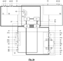
- the Figures 1a to 6 show different control and regulation systems to enable the operation of the oxygen reduction system. They show Figures 1a , 2a , 3a , 4a and 5a the control and regulation systems in connection with the other components of the oxygen reduction system.
- the Figures 1b , 2 B , 3b , 4b and 5b However, only show the signaling connections of the control and regulation systems with sensors and actuators. They are intended to provide a better overview of the architecture of the respective control and regulation system.
- FIGS. 1a and 1b show a control and regulation system of an oxygen reduction system according to the state of the art. So far, such systems for oxygen reduction systems have been implemented with a control center 20, which is connected in a star shape to the individual sensors 31a, 31b, 40, actuators 32, 33, 41 and alarm means 42 by means of field branch lines 50. How to do that Figures 1a and 1b As can be clearly seen, the individual connections between the control center 20 and the sensors 31a, 31b, 40, actuators 32, 33, 41 and alarm means 42 lead to a complex line architecture with, among other things, a large number of individual lines, long line lengths and the resulting increased susceptibility to failure.
- the control center 20 itself must be designed with high computing power and numerous interfaces in order to be able to reliably carry out all control and regulation functions. Subsequent expansions and reconfigurations, as well as troubleshooting fault reports, prove to be time-consuming and time-consuming.
- All exemplary embodiments of the invention include at least two controller modules 21, 22, 23, 24, 25, to which one or more control functions of the control and regulation system are decentrally distributed.
- the controller modules 21, 22, 23, 24, 25 are preferably constructed in a standardized manner, i.e. have essentially identical hardware components.
- the controller modules 21, 22, 23, 24, 25 each include similar or equivalent controllers and at least partially similar or equivalent communication interfaces.
- the controller modules 21, 22, 23, 24, 25 are signal-connected to one another and preferably configured differently. In particular, different control functions can be divided among the individual controller modules 21, 22, 23, 24, 25.
- the exemplary embodiment according to Figures 2a , 2 B shows, for example, a control and regulation system with two controller modules 22, 24.
- a combination controller 24 is provided, which combines the control functions of an area controller and a master controller and thus, on the one hand, monitors the oxygen concentration levels in the protected areas 10 and, on the other hand, coordinates the communication between them Controller modules 22, 24 and the other components of the oxygen reduction system.
- the further controller module is a controller module configured as a process controller 22 for controlling or regulating the inert gas generation by means of the two inert gas generators 30a, 30b.
- the combination controller 24 and the process controller 22 are spatially separated from one another.
- the process controller 22 is located in the machine room 12, in which the two inert gas generators 30a, 30b are also arranged.
- the combination controller 24, on the other hand, is located in a separate technical room 13. The spatial separation of the two controller modules 22, 24 increases reliability, shortens line lengths and improves the accessibility of the controller modules 22, 24.
- the combination controller 24 is connected to oxygen concentration sensors 40 and alarm means 42 in the protection areas 10 and the monitoring area 11. With the help of the oxygen concentration sensors 40, the combination controller 24 determines the oxygen concentration in the atmosphere of the protection areas 10 and the monitoring area 11. With a view to regulating the oxygen concentration in the protection areas 10, the combination controller 24 transmits a nitrogen requirement to the process controller 22, which controls the inert gas production based on the transmitted nitrogen requirement adapts and coordinates the introduction of the nitrogen-enriched air, for example via the control of the area valves 41. Alternatively, the area valves could be activated by a area controller as soon as it detects a nitrogen requirement.
- the process controller 22 is in turn signal-connected to pressure and oxygen concentration sensors 31a, 31b as well as actuators such as the compressors 33 and valves 32 of the inert gas generators 30a, 30b in order to control and regulate the inert gas production.
- the process controller 22 is not limited to the function of generating inert gas; In the present exemplary embodiment, it also assumes an area control function for the engine room 12 by monitoring the oxygen concentration of the engine room 12 with an oxygen concentration sensor 40 and, if necessary, if the oxygen falls below an oxygen threshold value, which can indicate a leak in the inert gas generators 30a, 30b, alarm means 42 in the Engine room 12 is controlled.
- connection paths between the controller modules 22, 24 and the associated sensors 31a, 31b, 40, actuators 32, 33, 41 and alarm means 42 are designed as field ring lines 51.
- the annular design means that cable routes can be saved and reliability is also increased thanks to redundant connection routes.
- Communication via the field ring lines 51 can take place, for example, via a CAN bus or RS485 with CANopen, Profibus or RTU-Modbus protocol.
- the combination controller 24 and the process controller 22 also communicate via an additional controller ring line 52, which is designed, for example, as an Ethernet connection.
- the combination controller 24 is also connected to the control panel 43, via which a user can monitor and influence the control and regulation functions.
- the Figures 3a , 3b show a further exemplary embodiment of the invention, with a total of four controller modules 21, 25 being provided.
- Two controller modules each form a master controller 21. These are signal-connected to one another, in particular via a controller ring line 52.
- the controller ring line 52 there are also two combination controllers 25, which in this exemplary embodiment combine the functions of an area controller and a process controller.
- the master controller 21 and the combination controller 25 are designed as redundant controller modules 21, 25, each of which forms a controller group and offers increased reliability due to the redundant design.
- the combination controllers 25 are connected via field ring lines 51 to the sensors 31a, 31b, 40, actuators 32, 33, 41 and alarm means 42 of the inert gas generators 30a, 30b, the protection areas 10, the monitoring area 11 and the machine room 12. They thus coordinate the inert gas generation by means of the inert gas generators 30a, 30b as well as the monitoring and regulation of the oxygen concentration in the individual areas 10, 11, 12.
- the master controllers 21 in the technical room 13, on the other hand, are responsible for coordinating the communication of the controller modules 21, 25 and for the display of fault and alarm messages or the receipt of user input using the control panel 43.
- the exemplary embodiment according to Figures 3a , 3b is characterized overall by a high level of redundancy and thus operational reliability.
- controller module 21, 25 that is not only constructed the same but also configured the same can fully take over the functions of the other controller module 21, 25.
- each controller module 21, 25 can directly access the sensors 31a, 31b, 40, actuators 32, 33, 41 and alarm means 42 of the other controller module 21, 25 without any detours .
- the Figures 4a , 4b show a similar architecture of a control and regulation system according to a further preferred embodiment.
- the control and regulation system points according to Fig. 4
- the master controllers 21 are responsible for coordinating the communication of the controller modules 21, 22, 23 as well as for displaying fault and alarm messages or receiving user input using the control panel 43.
- no combination controller is provided in the control and regulation system.
- the area controllers 23 are used to monitor the oxygen concentration in the protection areas 10 and in the monitoring area 11.
- the area controllers 23 are signal-connected to oxygen concentration sensors 40 in the areas 10, 11 and can also have alarm means 42 located in these areas 10, 11 in the event of a malfunction or alarm such as a harmful oxygen concentration.
- the process controllers 22 are used to control and regulate the inert gas generation by means of the inert gas generators 30a, 30b and are signal-connected to the pressure and oxygen concentration sensors 31a, 31b as well as to the valves 32, the compressors 33 and the area valves 41. In addition, in the exemplary embodiment shown, they fulfill an additional area controller function with regard to the machine room 12.
- the area controllers 23 and the process controllers 22 do not communicate directly with one another, but are connected to the master controller 21 via two controller ring lines 52.
- the master controllers 21 take over the coordination of the communication, for example processing a nitrogen requirement determined by the area controllers 23 and forwarding it to the process controllers 22.
- the exemplary embodiment according to Figures 4a and 4b is not only characterized by even greater redundancy and reliability compared to the exemplary embodiment Figures 3a , 3b but also shows a particular suitability for very large or complex oxygen reduction systems with high control and regulation requirements at the levels of inert gas generation, area monitoring and higher-level communication.
- the exemplary embodiment according to Figures 5a , 5b differs from the exemplary embodiment according to Figures 4a , 4b by connecting the sensors 40 and actuators 42 or the inert gas generators 30a, 30b to the area controllers 23 or process controllers 22.
- field branch lines 50 are provided instead of field ring lines. This saves the double connection of sensors and actuators and is therefore comparative cost-effective.
- the area valves 41 are controlled by the area controllers 23.
- Fig. 6 shows an extension of the exemplary embodiment according to Figures 5a , 5b .
- the control and regulation system is analogous to the exemplary embodiment according to Figures 5a , 5b educated.
- a total of two redundantly designed master controllers 21, two redundantly designed area controllers 23 and two redundantly designed process controllers 22 are provided.
- the area controllers 23 and process controllers 22 are signal-coupled to the master controllers 21 via controller ring lines 52.
- Fig. 6 further communication interfaces that can be provided on at least one of the master controllers 21.
- the master controller 21 can have an input interface for a weather station 67. Current environmental conditions of the surrounding atmosphere, for example wind speeds, can be incorporated into the control of the oxygen reduction system.
- a signal output can be provided which communicates with a permanently occupied location 68. This means that alarm and fault messages can be forwarded to suitable recipients so that countermeasures can be taken.
- a communication switching device controls communication to different external devices, such as a remote diagnostic module 63, which in turn can be connected to a WLAN router 64 or via the Internet 65 to an external remote support PC 66 a local support PC 62.
- a data storage and evaluation unit 61 also located locally, e.g. an industrial PC or server, can be used for logging all operating data and in particular for long-term evaluation of system data such as control parameters, sensor data, environmental data, energy consumption data and / or status , fault and alarm messages. This makes it possible, for example, to carry out predictive maintenance or determine relevant maintenance intervals.
- control and regulation system can be expanded in almost any way according to the exemplary embodiments described above.
- several master controllers 21, several area controllers 23, several process controllers 22 and/or several combination controllers 24, 25 can be provided.
- Control panel 22 Process controller 50 Field branch line 23 Range controller 51 Field ring main 24 Combination controller (master/area controller) 52 Regulator ring line 25 Combination controller (process/area controller) 60 Switch 30a Membrane nitrogen generator 61 Industry PC 30b Pressure swing adsorption nitrogen generator 62 Support PC 31a Oxygen concentration sensor 63 Remote diagnostic module 31b Pressure sensor 64 WLAN router 32 Valve 65 Internet 33 compressor 66 Remote support PC 34 Adsorbent container 67 Weather station 35 Buffer container 68 Permanently occupied position
Landscapes
- Health & Medical Sciences (AREA)
- Public Health (AREA)
- Business, Economics & Management (AREA)
- Emergency Management (AREA)
- Safety Devices In Control Systems (AREA)
- Accommodation For Nursing Or Treatment Tables (AREA)
- Control Of Non-Electrical Variables (AREA)
- Air Conditioning Control Device (AREA)
- Alarm Systems (AREA)
Claims (15)
- Système de commande et de régulation d'une installation de réduction d'oxygène pour abaisser et maintenir un niveau de concentration en oxygène dans au moins une zone de protection fermée, comprenant :- au moins un générateur de gaz inerte (30a, 30b),- au moins un capteur de concentration en oxygène (31a, 40),- au moins un actionneur (32, 33, 41) pour libérer du gaz inerte,dans lequelle système de commande et de régulation comprend plusieurs modules régulateurs (21, 22, 23, 24, 25) reliés entre eux par voie de signalisation, qui sont chacun configurés ou configurables de manière à pouvoir exécuter une ou plusieurs fonctions de régulation, les fonctions de régulation étant réparties de manière décentralisée sur au moins deux modules régulateurs (21, 22, 23, 24, 25) reliés entre eux par voie de signalisation,un module régulateur (21, 22, 23, 24, 25) est configuré comme régulateur maître (21) pour la coordination de la communication entre les composants de l'installation de réduction d'oxygène et/ou pour la coordination de la communication vers des postes externes de l'installation de réduction d'oxygène,un module régulateur (21, 22, 23, 24, 25) est configuré comme régulateur de zone (23) pour surveiller un niveau de concentration en oxygène dans une zone de surveillance fermée (11) et/ou pour réguler un niveau de concentration en oxygène dans au moins une zone de protection fermée (10),caractérisé en ce queles modules régulateurs (21, 22, 23, 24, 25) sont configurables dynamiquement en cours de fonctionnement, en particulier, un premier module régulateur (21, 22, 23, 24, 25) pouvant prendre en charge une ou plusieurs fonctions de régulation d'un deuxième module régulateur (21, 22, 23, 24, 25), et inversement.
- Système de commande et de régulation selon la revendication 1, caractérisé en ce que
les modules régulateurs (21, 22, 23, 24, 25) peuvent être combinés entre eux de manière modulaire, les modules régulateurs (21, 22, 23, 24, 25) étant chacun configurés ou configurables différemment par des entrées d'utilisateur appropriées via une interface d'entrée. - Système de commande et de régulation selon la revendication 1 ou 2, caractérisé en ce que
les modules régulateurs (21, 22, 23, 24, 25) sont chacun configurés ou configurables de telle sorte qu'au moins un module régulateur (21, 22, 23, 24, 25) respectif permet d'exécuter au moins une des fonctions de régulation suivantes :a) une commande ou une régulation de la génération de gaz inerte, en particulier par- la mise en marche et l'arrêt dudit au moins un générateur de gaz inerte (30a, 30b), et/ou- l'évaluation de signaux de capteur, en particulier dudit au moins un capteur de concentration en oxygène (31a, 40) et/ou d'autres capteurs de gaz, de température, de débit volumique et/ou de pression (31b) associés audit au moins un générateur de gaz inerte (30a, 30b), et/ou- le pilotage d'actionneurs (32, 33, 41) dudit au moins un générateur de gaz inerte (30a, 30b) ;b) une surveillance d'un niveau de concentration en oxygène dans une zone de surveillance fermée (11) et/ou une commande ou une régulation d'un niveau de concentration en oxygène dans ladite au moins une zone de protection fermée (10), en particulier par- l'évaluation de signaux de capteurs, en particulier dudit au moins un capteur de concentration en oxygène (31a, 40) et/ou d'autres signaux de capteurs de gaz, de température, de débit volumique et/ou de pression de capteurs disposés dans ladite au moins une zone de surveillance (11) et/ou de protection (10) fermée, et/ou par
l'évaluation de signaux de contacts d'ouverture de porte disposés dans la zone de surveillance et/ou de protection (10), et/ou- la demande d'une quantité de gaz inerte provenant dudit au moins un générateur de gaz inerte (30a, 30b), et/ou- le pilotage d'actionneurs dans ladite au moins une zone de surveillance (11) et/ou de protection (10) fermée, et/ou- le pilotage d'affichages dans ou sur ladite au moins une zone de surveillance et/ou de protection (10) fermée, en particulier pour afficher des valeurs de mesure de la concentration en oxygène, et/ou- le pilotage de moyens d'alarme acoustiques et/ou optiques (42) en cas d'alarme ;c) une coordination de la communication entre les composants de l'installation de réduction d'oxygène et/ou une coordination de la communication vers des postes externes de l'installation de réduction d'oxygène, en particulier par- la répartition des demandes de quantités de gaz inerte sur plusieurs générateurs de gaz inerte (30a, 30b) selon des critères prédéfinis, et/ou- la collecte et l'évaluation d'au moins un signal d'état, de dysfonctionnement et/ou d'alarme d'au moins un module régulateur (21, 22, 23, 24, 25), et/ou- la génération d'au moins un message d'état, de dysfonctionnement et/ou d'alarme, en particulier pour l'affichage sur un panneau de commande (43) et/ou pour la transmission à un poste externe (68), en particulier occupé en permanence, et/ou- le pilotage d'affichages, en particulier pour afficher des valeurs de mesure de capteurs, et/ou- la fourniture d'un accès à distance au système de réduction d'oxygène. - Système de commande et de régulation selon la revendication 3, caractérisé en ce que
il est prévu, en tant que module régulateur (21, 22, 23, 24, 25), un régulateur de processus (22) pour commander ou réguler la génération de gaz inerte. - Système de commande et de régulation selon la revendication 4, caractérisé en ce que
il est prévu plusieurs zones de surveillance (11) et/ou de protection (10), et- au moins un régulateur de zone (23) pour commander ou réguler un niveau de concentration en oxygène dans la zone de protection (10) est associé à chaque zone de protection (10), et/ou- au moins un régulateur de zone (23) pour surveiller un niveau de concentration en oxygène dans la zone de surveillance (11) est associé à chaque zone de surveillance (11). - Système de commande et de régulation selon l'une des revendications 3 à 5,
caractérisé en ce que
il est prévu, en tant que module régulateur (21, 22, 23, 24, 25), un régulateur combiné (24, 25) qui comprend des fonctions de régulation d'au moins deux modules régulateurs (21, 22, 23, 24, 25) qui sont réalisés ou configurés ou configurables comme régulateur maître (21), comme régulateur de zone (23) ou comme régulateur de processus (22). - Système de commande et de régulation selon l'une des revendications précédentes,
caractérisé en ce que
au moins deux modules régulateurs (21, 22, 23, 24, 25) présentent une gamme de fonctions identique et sont reliés entre eux par voie de signalisation de manière à former un groupe de régulateurs redondant en soi. - Système de commande et de régulation selon l'une des revendications précédentes,
caractérisé en ce que
les modules régulateurs (21, 22, 23, 24, 25), en particulier les modules régulateurs (21, 22, 23, 24, 25) d'un groupe de régulateurs, sont chacun réalisés et reliés entre eux par voie de signalisation de telle sorte qu'un module régulateur (21, 22, 23, 24, 25), en cas de défaillance et/ou de surcharge d'un autre module régulateur (21, 22, 23, 24, 25), prend en charge de manière automatisée sa fonction de régulation ou ses fonctions de régulation. - Système de commande et de régulation selon l'une des revendications précédentes,
caractérisé en ce que
les modules régulateurs (21, 22, 23, 24, 25) et/ou groupes de régulateurs individuels sont disposés séparément les uns des autres dans l'espace. - Système de commande et de régulation selon l'une des revendications précédentes,
caractérisé en ce que
les modules régulateurs (21, 22, 23, 24, 25) sont reliés par voie de signalisation ou peuvent être reliés par voie de signalisation à une unité de mémorisation et d'évaluation de données (61), de manière à permettre de réaliser une mémorisation et une évaluation à long terme de données du système, en particulier de paramètres de régulation, de données de capteurs, de données environnementales, de données de consommation d'énergie et/ou de messages d'état, de dysfonctionnement et d'alarme. - Système de commande et de régulation selon l'une des revendications précédentes,
caractérisé en ce que
les modules régulateurs (21, 22, 23, 24, 25) présentent chacun une fonction de reconnaissance de périphériques de telle sorte que le type et le mode de fonctionnement de capteurs de concentration en oxygène (31a, 40) et/ou d'actionneurs (32, 33, 41) et/ou d'autres capteurs (31b), raccordés au module régulateur respectif (21, 22, 23, 24, 25), peuvent être reconnus de manière automatisée. - Système de commande et de régulation selon la revendication 10,
caractérisé en ce que
les modules régulateurs (21, 22, 23, 24, 25) sont conçus de manière auto-configurable de telle sorte que des fonctions de régulation sont activées et/ou désactivées de manière automatisée à l'aide du type et du mode de fonctionnement respectifs des capteurs de concentration en oxygène (31a, 40) et/ou des actionneurs (32, 33, 41) et/ou d'autres capteurs (31b), raccordés, ou à l'aide de leurs interfaces d'entrée/sortie. - Système de commande et de régulation selon l'une des revendications précédentes, en particulier selon l'une des revendications 3 à 11,
caractérisé en ce que
ledit au moins un module régulateur (21, 22, 23, 24, 25), en particulier le régulateur de processus (22) et/ou le régulateur maître (21), est configuré de telle sorte qu'une répartition du gaz inerte selon des critères prédéterminés est effectuée de telle sorte que plusieurs générateurs de gaz inerte (30a, 30b) présentent des durées de fonctionnement sensiblement identiques. - Installation de réduction d'oxygène, en particulier installation de protection contre l'incendie, comportant un système de commande et de régulation selon l'une des revendications précédentes.
- Procédé de commande et/ou de régulation d'une installation de réduction d'oxygène selon la revendication 14, dans lequel un ou plusieurs modules régulateurs (21, 22, 23, 24, 25) sont configurés pour exécuter au moins une des fonctions de régulation suivantes :- une commande ou une régulation du générateur de gaz inerte (30a, 30b),- une évaluation d'un signal de concentration en oxygène du capteur de concentration en oxygène (31a, 40), et- un pilotage de l'actionneur (32, 33, 41) pour libérer du gaz inerte ;dans lequel des fonctions de régulation différentes sont attribuées aux modules régulateurs (21, 22, 23, 24, 25) individuels en cours de fonctionnement, et les modules régulateurs (21, 22, 23, 24, 25) sont chacun conçus et reliés entre eux par voie de signalisation de telle sorte qu'en cas de défaillance d'un module régulateur (21, 22, 23, 24, 25), ses fonctions de régulation sont prises en charge de manière automatisée par un autre module régulateur (21, 22, 23, 24, 25).
Priority Applications (8)
| Application Number | Priority Date | Filing Date | Title |
|---|---|---|---|
| EP18020204.6A EP3569290B1 (fr) | 2018-05-14 | 2018-05-14 | Système de commande et de réglage d'une installation de réduction d'oxygène |
| CA3099363A CA3099363A1 (fr) | 2018-05-14 | 2019-05-09 | Systeme de commande et de regulation d'une installation de reduction d'oxygene |
| CN201980031853.2A CN112188920A (zh) | 2018-05-14 | 2019-05-09 | 氧气减少系统的控制和调节系统 |
| AU2019270136A AU2019270136A1 (en) | 2018-05-14 | 2019-05-09 | Open-loop and closed-loop control system of a deoxygenation plant |
| MX2020012085A MX2020012085A (es) | 2018-05-14 | 2019-05-09 | Sistema de control y regulacion de un sistema reductor de oxigeno. |
| PCT/EP2019/061910 WO2019219494A1 (fr) | 2018-05-14 | 2019-05-09 | Système de commande et de régulation d'une installation de réduction d'oxygène |
| US17/055,091 US11745037B2 (en) | 2018-05-14 | 2019-05-09 | Open-loop and closed-loop control system of a deoxygenation plant |
| ZA2020/06543A ZA202006543B (en) | 2018-05-14 | 2020-10-21 | Open-loop and closed-loop control system of a deoxygenation plant |
Applications Claiming Priority (1)
| Application Number | Priority Date | Filing Date | Title |
|---|---|---|---|
| EP18020204.6A EP3569290B1 (fr) | 2018-05-14 | 2018-05-14 | Système de commande et de réglage d'une installation de réduction d'oxygène |
Publications (2)
| Publication Number | Publication Date |
|---|---|
| EP3569290A1 EP3569290A1 (fr) | 2019-11-20 |
| EP3569290B1 true EP3569290B1 (fr) | 2024-02-14 |
Family
ID=62165294
Family Applications (1)
| Application Number | Title | Priority Date | Filing Date |
|---|---|---|---|
| EP18020204.6A Active EP3569290B1 (fr) | 2018-05-14 | 2018-05-14 | Système de commande et de réglage d'une installation de réduction d'oxygène |
Country Status (8)
| Country | Link |
|---|---|
| US (1) | US11745037B2 (fr) |
| EP (1) | EP3569290B1 (fr) |
| CN (1) | CN112188920A (fr) |
| AU (1) | AU2019270136A1 (fr) |
| CA (1) | CA3099363A1 (fr) |
| MX (1) | MX2020012085A (fr) |
| WO (1) | WO2019219494A1 (fr) |
| ZA (1) | ZA202006543B (fr) |
Families Citing this family (3)
| Publication number | Priority date | Publication date | Assignee | Title |
|---|---|---|---|---|
| DE102020107319A1 (de) * | 2020-03-17 | 2021-09-23 | BSS Sonderlöschanlagen GmbH | Brandschutzsteuerungsvorrichtung, brandschutzvorrichtung, brandschutzsteuerungsverfahren |
| CN113914680A (zh) * | 2021-08-31 | 2022-01-11 | 浙江天脉数据科技有限公司 | 一种使用高压惰性气体的数据方舱系统 |
| CN115067387A (zh) * | 2022-07-21 | 2022-09-20 | 杭州辰睿空分设备制造有限公司 | 一种制氮系统的远程式智能控制系统 |
Family Cites Families (22)
| Publication number | Priority date | Publication date | Assignee | Title |
|---|---|---|---|---|
| CA2023707C (fr) * | 1989-09-28 | 1999-02-23 | Richard W. Hradek | Oxygenoconcentrateur muni d'un surpresseur et d'un indicateur de concentration |
| US5058004A (en) | 1990-01-19 | 1991-10-15 | Gonen Ravid | Computer gate control circuitry and apparatus to enable a single computer to simultaneously and selectively control a multiplicity of hard disk drives |
| WO1995001041A1 (fr) | 1993-06-23 | 1995-01-05 | Feinberg David H | Systeme integre de telephonie, d'intercommunication, de securite et de commande destine a un batiment comprenant plusieurs unites |
| JPH07154391A (ja) | 1993-11-26 | 1995-06-16 | Hitachi Ltd | スイッチ制御部の系切替方式 |
| DE19811851C2 (de) * | 1998-03-18 | 2001-01-04 | Wagner Alarm Sicherung | Inertisierungsverfahren zur Brandverhütung und -löschung in geschlossenen Räumen |
| US20020040940A1 (en) * | 1998-03-18 | 2002-04-11 | Wagner Ernst Werner | Inerting method and apparatus for preventing and extinguishing fires in enclosed spaces |
| PL1683548T3 (pl) * | 2005-01-21 | 2013-04-30 | Amrona Ag | Sposób inertyzacji w celu przeciwdziałania pożarom |
| JP4641844B2 (ja) * | 2005-03-25 | 2011-03-02 | 大日本印刷株式会社 | 電子線照射装置 |
| WO2007011979A2 (fr) * | 2005-07-19 | 2007-01-25 | Pacific Consolidated Industries, Llc | Generateur d'azote mobile |
| RU58761U1 (ru) | 2006-07-03 | 2006-11-27 | Научно-производственный кооператив "Авиаинформатика" | Интегрированная система мониторинга контролируемых объектов |
| ES2380458T3 (es) * | 2006-12-08 | 2012-05-11 | Amrona Ag | Método y dispositivo para la alimentación regulada de suministro de aire |
| UA97990C2 (uk) * | 2007-08-01 | 2012-04-10 | Амрона Аг | Пристрій та спосіб запобігання пожежам та гасіння пожежі, яка зайнялася у замкнутій зоні |
| DE102009030703B4 (de) | 2009-06-26 | 2016-09-01 | Airbus Operations Gmbh | Luftfrachtbehälterüberwachungsvorrichtung und -verfahren |
| US9300137B2 (en) | 2010-07-29 | 2016-03-29 | Spirae, Inc. | Dynamic distributed power grid control system |
| RU113855U1 (ru) | 2011-09-02 | 2012-02-27 | Научно-Производственное Частное Унитарное Предприятие "Фарнелл" | Модуль регистрации и обработки диагностической информации для летательных аппаратов |
| US9016078B2 (en) * | 2011-11-17 | 2015-04-28 | The Boeing Company | Fuel tank flammability reduction and inerting system and methods thereof |
| ES2593602T3 (es) | 2013-05-06 | 2016-12-12 | Amrona Ag | Procedimiento de inertización así como instalación para la reducción cuantitativa del oxígeno |
| EP2881149B1 (fr) * | 2013-12-04 | 2018-02-28 | Amrona AG | Installation de réduction d'oxygène et procédé de fonctionnement d'une installation de réduction d'oxygène |
| EP3011999B1 (fr) * | 2014-10-24 | 2017-08-16 | Amrona AG | Système et procédé de réduction d'oxygène dans un espace cible |
| CN118615619A (zh) * | 2015-01-22 | 2024-09-10 | 赛峰航空技术股份公司 | 航空器机载的用于防火的燃料电池设备 |
| US10933262B2 (en) * | 2015-12-22 | 2021-03-02 | WAGNER Fire Safety, Inc. | Oxygen-reducing installation and method for operating an oxygen-reducing installation |
| CN108430592A (zh) * | 2015-12-22 | 2018-08-21 | 艾摩罗那股份公司 | 氧气降低系统和用于操作氧气降低系统的方法 |
-
2018
- 2018-05-14 EP EP18020204.6A patent/EP3569290B1/fr active Active
-
2019
- 2019-05-09 US US17/055,091 patent/US11745037B2/en active Active
- 2019-05-09 AU AU2019270136A patent/AU2019270136A1/en active Pending
- 2019-05-09 CA CA3099363A patent/CA3099363A1/fr active Pending
- 2019-05-09 CN CN201980031853.2A patent/CN112188920A/zh active Pending
- 2019-05-09 MX MX2020012085A patent/MX2020012085A/es unknown
- 2019-05-09 WO PCT/EP2019/061910 patent/WO2019219494A1/fr active Application Filing
-
2020
- 2020-10-21 ZA ZA2020/06543A patent/ZA202006543B/en unknown
Also Published As
| Publication number | Publication date |
|---|---|
| AU2019270136A1 (en) | 2020-11-26 |
| WO2019219494A1 (fr) | 2019-11-21 |
| US11745037B2 (en) | 2023-09-05 |
| CA3099363A1 (fr) | 2019-11-21 |
| EP3569290A1 (fr) | 2019-11-20 |
| ZA202006543B (en) | 2022-07-27 |
| CN112188920A (zh) | 2021-01-05 |
| MX2020012085A (es) | 2021-02-09 |
| US20210121723A1 (en) | 2021-04-29 |
Similar Documents
| Publication | Publication Date | Title |
|---|---|---|
| DE3803892A1 (de) | Gaswarnanlage | |
| EP3569290B1 (fr) | Système de commande et de réglage d'une installation de réduction d'oxygène | |
| EP1642179B1 (fr) | Dispositif pour commander de maniere automatisee le deroulement d'une operation dans une installation technique | |
| EP3622357B1 (fr) | Système de commande servant à commander des processus critiques pour la sécurité et non-critiques pour la sécurité, muni d'une fonctionnalité maître-esclave | |
| WO2009121619A1 (fr) | Système assisté par ordinateur pour l'administration et/ou la commande d'un système de gestion d'immeuble | |
| EP3441958B1 (fr) | Module de commande et de surveillance | |
| DE102008060005A1 (de) | Sicherheitssteuerung und Verfahren zum Steuern einer automatisierten Anlage mit einer Vielzahl von Anlagenhardwarekomponenten | |
| WO2012175193A1 (fr) | Système de commande destiné au stockage temporaire et au transport de récipients sur des voies de transport | |
| EP2423897B1 (fr) | Installation d'alerte aux dangers et son procédé de fonctionnement | |
| EP2393073B1 (fr) | Procédé destiné au fonctionnement d'une installation d'alerte aux dangers | |
| EP3557598A1 (fr) | Commutateur de sécurité | |
| DE102004041824A1 (de) | Schiff mit einem Datennetzwerk | |
| WO2022248178A1 (fr) | Système d'ascenseurs et procédé de fonctionnement d'un système d'ascenseurs de ce type | |
| DE3611597A1 (de) | Zentrale fahrtreppen-fernueberwachungsanordnung | |
| EP0809162B1 (fr) | Méthode et dispositif de commande d'appareil | |
| EP1881652A1 (fr) | Système de bus de terrain composé de noeds avec surveillance de bus intégrée | |
| WO2021001206A1 (fr) | Procédé de vérification destiné à un système de réduction d'oxygène | |
| WO2016079091A1 (fr) | Procédé de fonctionnement d'un premier et d'au moins un deuxième appareil de terrain | |
| EP1692578A1 (fr) | Unite peripherique d'un systeme de commande redondant | |
| DD254454A5 (de) | Vorrichtung und verfahren zum regeln und steuern von chemischen und physikalischen vorgaengen in einer vielzahl von dafuer geeigneten apparaten | |
| DE102018103730B4 (de) | System zur Steuerung einer technischen Anlage im Bereich der Automation eines Gebäudes | |
| DE102015109687A1 (de) | Modulare Sicherheitssteuerung | |
| DE202015103189U1 (de) | Modulare Sicherheitssteuerung | |
| EP1062550A1 (fr) | Procede et dispositif de traitement de donnees d'une installation technique, ces donnees etant specifiques utilisateur et enregistrees dans differentes memoires donnees | |
| WO2024200633A1 (fr) | Centre, procédé et programme informatique pour configurer un centre |
Legal Events
| Date | Code | Title | Description |
|---|---|---|---|
| PUAI | Public reference made under article 153(3) epc to a published international application that has entered the european phase |
Free format text: ORIGINAL CODE: 0009012 |
|
| STAA | Information on the status of an ep patent application or granted ep patent |
Free format text: STATUS: THE APPLICATION HAS BEEN PUBLISHED |
|
| AK | Designated contracting states |
Kind code of ref document: A1 Designated state(s): AL AT BE BG CH CY CZ DE DK EE ES FI FR GB GR HR HU IE IS IT LI LT LU LV MC MK MT NL NO PL PT RO RS SE SI SK SM TR |
|
| AX | Request for extension of the european patent |
Extension state: BA ME |
|
| STAA | Information on the status of an ep patent application or granted ep patent |
Free format text: STATUS: REQUEST FOR EXAMINATION WAS MADE |
|
| 17P | Request for examination filed |
Effective date: 20200513 |
|
| RBV | Designated contracting states (corrected) |
Designated state(s): AL AT BE BG CH CY CZ DE DK EE ES FI FR GB GR HR HU IE IS IT LI LT LU LV MC MK MT NL NO PL PT RO RS SE SI SK SM TR |
|
| STAA | Information on the status of an ep patent application or granted ep patent |
Free format text: STATUS: EXAMINATION IS IN PROGRESS |
|
| 17Q | First examination report despatched |
Effective date: 20220302 |
|
| P01 | Opt-out of the competence of the unified patent court (upc) registered |
Effective date: 20230526 |
|
| GRAP | Despatch of communication of intention to grant a patent |
Free format text: ORIGINAL CODE: EPIDOSNIGR1 |
|
| STAA | Information on the status of an ep patent application or granted ep patent |
Free format text: STATUS: GRANT OF PATENT IS INTENDED |
|
| INTG | Intention to grant announced |
Effective date: 20230918 |
|
| GRAS | Grant fee paid |
Free format text: ORIGINAL CODE: EPIDOSNIGR3 |
|
| GRAA | (expected) grant |
Free format text: ORIGINAL CODE: 0009210 |
|
| STAA | Information on the status of an ep patent application or granted ep patent |
Free format text: STATUS: THE PATENT HAS BEEN GRANTED |
|
| AK | Designated contracting states |
Kind code of ref document: B1 Designated state(s): AL AT BE BG CH CY CZ DE DK EE ES FI FR GB GR HR HU IE IS IT LI LT LU LV MC MK MT NL NO PL PT RO RS SE SI SK SM TR |
|
| REG | Reference to a national code |
Ref country code: GB Ref legal event code: FG4D Free format text: NOT ENGLISH |
|
| REG | Reference to a national code |
Ref country code: CH Ref legal event code: EP |
|
| REG | Reference to a national code |
Ref country code: DE Ref legal event code: R096 Ref document number: 502018014093 Country of ref document: DE |
|
| REG | Reference to a national code |
Ref country code: IE Ref legal event code: FG4D Free format text: LANGUAGE OF EP DOCUMENT: GERMAN |
|
| REG | Reference to a national code |
Ref country code: NL Ref legal event code: FP |
|
| REG | Reference to a national code |
Ref country code: LT Ref legal event code: MG9D |
|
| PGFP | Annual fee paid to national office [announced via postgrant information from national office to epo] |
Ref country code: NL Payment date: 20240521 Year of fee payment: 7 |
|
| PG25 | Lapsed in a contracting state [announced via postgrant information from national office to epo] |
Ref country code: IS Free format text: LAPSE BECAUSE OF FAILURE TO SUBMIT A TRANSLATION OF THE DESCRIPTION OR TO PAY THE FEE WITHIN THE PRESCRIBED TIME-LIMIT Effective date: 20240614 |
|
| PGFP | Annual fee paid to national office [announced via postgrant information from national office to epo] |
Ref country code: GB Payment date: 20240521 Year of fee payment: 7 |
|
| PG25 | Lapsed in a contracting state [announced via postgrant information from national office to epo] |
Ref country code: LT Free format text: LAPSE BECAUSE OF FAILURE TO SUBMIT A TRANSLATION OF THE DESCRIPTION OR TO PAY THE FEE WITHIN THE PRESCRIBED TIME-LIMIT Effective date: 20240214 |
|
| PGFP | Annual fee paid to national office [announced via postgrant information from national office to epo] |
Ref country code: DE Payment date: 20240521 Year of fee payment: 7 |
|
| PG25 | Lapsed in a contracting state [announced via postgrant information from national office to epo] |
Ref country code: GR Free format text: LAPSE BECAUSE OF FAILURE TO SUBMIT A TRANSLATION OF THE DESCRIPTION OR TO PAY THE FEE WITHIN THE PRESCRIBED TIME-LIMIT Effective date: 20240515 |
|
| PG25 | Lapsed in a contracting state [announced via postgrant information from national office to epo] |
Ref country code: RS Free format text: LAPSE BECAUSE OF FAILURE TO SUBMIT A TRANSLATION OF THE DESCRIPTION OR TO PAY THE FEE WITHIN THE PRESCRIBED TIME-LIMIT Effective date: 20240514 Ref country code: HR Free format text: LAPSE BECAUSE OF FAILURE TO SUBMIT A TRANSLATION OF THE DESCRIPTION OR TO PAY THE FEE WITHIN THE PRESCRIBED TIME-LIMIT Effective date: 20240214 |
|
| PGFP | Annual fee paid to national office [announced via postgrant information from national office to epo] |
Ref country code: CH Payment date: 20240602 Year of fee payment: 7 |
|
| PG25 | Lapsed in a contracting state [announced via postgrant information from national office to epo] |
Ref country code: ES Free format text: LAPSE BECAUSE OF FAILURE TO SUBMIT A TRANSLATION OF THE DESCRIPTION OR TO PAY THE FEE WITHIN THE PRESCRIBED TIME-LIMIT Effective date: 20240214 |
|
| PGFP | Annual fee paid to national office [announced via postgrant information from national office to epo] |
Ref country code: AT Payment date: 20240522 Year of fee payment: 7 |
|
| PG25 | Lapsed in a contracting state [announced via postgrant information from national office to epo] |
Ref country code: RS Free format text: LAPSE BECAUSE OF FAILURE TO SUBMIT A TRANSLATION OF THE DESCRIPTION OR TO PAY THE FEE WITHIN THE PRESCRIBED TIME-LIMIT Effective date: 20240514 Ref country code: NO Free format text: LAPSE BECAUSE OF FAILURE TO SUBMIT A TRANSLATION OF THE DESCRIPTION OR TO PAY THE FEE WITHIN THE PRESCRIBED TIME-LIMIT Effective date: 20240514 Ref country code: LT Free format text: LAPSE BECAUSE OF FAILURE TO SUBMIT A TRANSLATION OF THE DESCRIPTION OR TO PAY THE FEE WITHIN THE PRESCRIBED TIME-LIMIT Effective date: 20240214 Ref country code: IS Free format text: LAPSE BECAUSE OF FAILURE TO SUBMIT A TRANSLATION OF THE DESCRIPTION OR TO PAY THE FEE WITHIN THE PRESCRIBED TIME-LIMIT Effective date: 20240614 Ref country code: HR Free format text: LAPSE BECAUSE OF FAILURE TO SUBMIT A TRANSLATION OF THE DESCRIPTION OR TO PAY THE FEE WITHIN THE PRESCRIBED TIME-LIMIT Effective date: 20240214 Ref country code: GR Free format text: LAPSE BECAUSE OF FAILURE TO SUBMIT A TRANSLATION OF THE DESCRIPTION OR TO PAY THE FEE WITHIN THE PRESCRIBED TIME-LIMIT Effective date: 20240515 Ref country code: FI Free format text: LAPSE BECAUSE OF FAILURE TO SUBMIT A TRANSLATION OF THE DESCRIPTION OR TO PAY THE FEE WITHIN THE PRESCRIBED TIME-LIMIT Effective date: 20240214 Ref country code: ES Free format text: LAPSE BECAUSE OF FAILURE TO SUBMIT A TRANSLATION OF THE DESCRIPTION OR TO PAY THE FEE WITHIN THE PRESCRIBED TIME-LIMIT Effective date: 20240214 Ref country code: BG Free format text: LAPSE BECAUSE OF FAILURE TO SUBMIT A TRANSLATION OF THE DESCRIPTION OR TO PAY THE FEE WITHIN THE PRESCRIBED TIME-LIMIT Effective date: 20240214 |
|
| PGFP | Annual fee paid to national office [announced via postgrant information from national office to epo] |
Ref country code: FR Payment date: 20240528 Year of fee payment: 7 |
|
| PG25 | Lapsed in a contracting state [announced via postgrant information from national office to epo] |
Ref country code: PL Free format text: LAPSE BECAUSE OF FAILURE TO SUBMIT A TRANSLATION OF THE DESCRIPTION OR TO PAY THE FEE WITHIN THE PRESCRIBED TIME-LIMIT Effective date: 20240214 Ref country code: PT Free format text: LAPSE BECAUSE OF FAILURE TO SUBMIT A TRANSLATION OF THE DESCRIPTION OR TO PAY THE FEE WITHIN THE PRESCRIBED TIME-LIMIT Effective date: 20240614 |
|
| PG25 | Lapsed in a contracting state [announced via postgrant information from national office to epo] |
Ref country code: SE Free format text: LAPSE BECAUSE OF FAILURE TO SUBMIT A TRANSLATION OF THE DESCRIPTION OR TO PAY THE FEE WITHIN THE PRESCRIBED TIME-LIMIT Effective date: 20240214 Ref country code: PT Free format text: LAPSE BECAUSE OF FAILURE TO SUBMIT A TRANSLATION OF THE DESCRIPTION OR TO PAY THE FEE WITHIN THE PRESCRIBED TIME-LIMIT Effective date: 20240614 Ref country code: PL Free format text: LAPSE BECAUSE OF FAILURE TO SUBMIT A TRANSLATION OF THE DESCRIPTION OR TO PAY THE FEE WITHIN THE PRESCRIBED TIME-LIMIT Effective date: 20240214 Ref country code: LV Free format text: LAPSE BECAUSE OF FAILURE TO SUBMIT A TRANSLATION OF THE DESCRIPTION OR TO PAY THE FEE WITHIN THE PRESCRIBED TIME-LIMIT Effective date: 20240214 |
|
| PGFP | Annual fee paid to national office [announced via postgrant information from national office to epo] |
Ref country code: IT Payment date: 20240530 Year of fee payment: 7 |
|
| PG25 | Lapsed in a contracting state [announced via postgrant information from national office to epo] |
Ref country code: DK Free format text: LAPSE BECAUSE OF FAILURE TO SUBMIT A TRANSLATION OF THE DESCRIPTION OR TO PAY THE FEE WITHIN THE PRESCRIBED TIME-LIMIT Effective date: 20240214 |
|
| PG25 | Lapsed in a contracting state [announced via postgrant information from national office to epo] |
Ref country code: SM Free format text: LAPSE BECAUSE OF FAILURE TO SUBMIT A TRANSLATION OF THE DESCRIPTION OR TO PAY THE FEE WITHIN THE PRESCRIBED TIME-LIMIT Effective date: 20240214 |