EP3568599B1 - Ejektor - Google Patents
Ejektor Download PDFInfo
- Publication number
- EP3568599B1 EP3568599B1 EP18700802.4A EP18700802A EP3568599B1 EP 3568599 B1 EP3568599 B1 EP 3568599B1 EP 18700802 A EP18700802 A EP 18700802A EP 3568599 B1 EP3568599 B1 EP 3568599B1
- Authority
- EP
- European Patent Office
- Prior art keywords
- deflector
- rotational
- ejector device
- motive fluid
- deflector element
- Prior art date
- Legal status (The legal status is an assumption and is not a legal conclusion. Google has not performed a legal analysis and makes no representation as to the accuracy of the status listed.)
- Active
Links
Images




Classifications
-
- F—MECHANICAL ENGINEERING; LIGHTING; HEATING; WEAPONS; BLASTING
- F04—POSITIVE - DISPLACEMENT MACHINES FOR LIQUIDS; PUMPS FOR LIQUIDS OR ELASTIC FLUIDS
- F04F—PUMPING OF FLUID BY DIRECT CONTACT OF ANOTHER FLUID OR BY USING INERTIA OF FLUID TO BE PUMPED; SIPHONS
- F04F1/00—Pumps using positively or negatively pressurised fluid medium acting directly on the liquid to be pumped
- F04F1/18—Pumps using positively or negatively pressurised fluid medium acting directly on the liquid to be pumped the fluid medium being mixed with, or generated from the liquid to be pumped
-
- F—MECHANICAL ENGINEERING; LIGHTING; HEATING; WEAPONS; BLASTING
- F04—POSITIVE - DISPLACEMENT MACHINES FOR LIQUIDS; PUMPS FOR LIQUIDS OR ELASTIC FLUIDS
- F04F—PUMPING OF FLUID BY DIRECT CONTACT OF ANOTHER FLUID OR BY USING INERTIA OF FLUID TO BE PUMPED; SIPHONS
- F04F5/00—Jet pumps, i.e. devices in which flow is induced by pressure drop caused by velocity of another fluid flow
- F04F5/42—Jet pumps, i.e. devices in which flow is induced by pressure drop caused by velocity of another fluid flow characterised by the input flow of inducing fluid medium being radial or tangential to output flow
-
- F—MECHANICAL ENGINEERING; LIGHTING; HEATING; WEAPONS; BLASTING
- F04—POSITIVE - DISPLACEMENT MACHINES FOR LIQUIDS; PUMPS FOR LIQUIDS OR ELASTIC FLUIDS
- F04F—PUMPING OF FLUID BY DIRECT CONTACT OF ANOTHER FLUID OR BY USING INERTIA OF FLUID TO BE PUMPED; SIPHONS
- F04F5/00—Jet pumps, i.e. devices in which flow is induced by pressure drop caused by velocity of another fluid flow
- F04F5/02—Jet pumps, i.e. devices in which flow is induced by pressure drop caused by velocity of another fluid flow the inducing fluid being liquid
- F04F5/04—Jet pumps, i.e. devices in which flow is induced by pressure drop caused by velocity of another fluid flow the inducing fluid being liquid displacing elastic fluids
-
- F—MECHANICAL ENGINEERING; LIGHTING; HEATING; WEAPONS; BLASTING
- F04—POSITIVE - DISPLACEMENT MACHINES FOR LIQUIDS; PUMPS FOR LIQUIDS OR ELASTIC FLUIDS
- F04F—PUMPING OF FLUID BY DIRECT CONTACT OF ANOTHER FLUID OR BY USING INERTIA OF FLUID TO BE PUMPED; SIPHONS
- F04F5/00—Jet pumps, i.e. devices in which flow is induced by pressure drop caused by velocity of another fluid flow
- F04F5/44—Component parts, details, or accessories not provided for in, or of interest apart from, groups F04F5/02 - F04F5/42
- F04F5/46—Arrangements of nozzles
-
- F—MECHANICAL ENGINEERING; LIGHTING; HEATING; WEAPONS; BLASTING
- F04—POSITIVE - DISPLACEMENT MACHINES FOR LIQUIDS; PUMPS FOR LIQUIDS OR ELASTIC FLUIDS
- F04F—PUMPING OF FLUID BY DIRECT CONTACT OF ANOTHER FLUID OR BY USING INERTIA OF FLUID TO BE PUMPED; SIPHONS
- F04F5/00—Jet pumps, i.e. devices in which flow is induced by pressure drop caused by velocity of another fluid flow
- F04F5/44—Component parts, details, or accessories not provided for in, or of interest apart from, groups F04F5/02 - F04F5/42
- F04F5/46—Arrangements of nozzles
- F04F5/463—Arrangements of nozzles with provisions for mixing
Definitions
- This invention relates to an ejector device. More particularly, though not exclusively, it relates to an ejector device for the pumping of fluids. The invention relates even more particularly, though not exclusively, to a fluid inlet or injector arrangement for use in such an ejector device.
- Ejector devices are well known for the pumping of fluids, e.g. liquids or gases.
- Known ejector devices typically employ a relatively high pressure fluid (the "motive” fluid) to compress a relatively low pressure fluid (the “entrained” or “suction” fluid) to an intermediate pressure. The fluid at intermediate pressure is then ejected from the ejector device as a “discharge” fluid.
- Examples of such ejector devices which employ a motive liquid to pressurise a gas may often be termed a "liquid jet compressor” or a “Venturi pump”.
- Ejector devices have an advantage over many conventional mechanical pumps in that they can have substantially no moving parts, so may therefore enjoy a substantially longer service life in many practical applications.
- FIG. 1 of the accompanying drawings shows an example of a typical known form of ejector device.
- the ejector device 1 has a motive fluid inlet portion 10 through which a motive fluid can enter the device 1.
- the motive fluid may for example be pumped by a pump (not shown) into and through the motive fluid inlet or injector portion 10.
- the velocity of the motive fluid increases as it passes through a conical nozzle portion 40 of the device 1 before being injected through an outlet aperture 44 of the nozzle portion 40 at an apex thereof into an inlet aperture 52 of a diffuser portion 50.
- the diffuser portion 50 provides a fluid conduit in the form of a Venturi tube, in which, passing from the inlet aperture 52 of the diffuser portion 50 towards an outlet aperture 54 thereof, a diameter of the conduit initially decreases along a first length of the diffuser portion 50 to a diameter less than that of the inlet aperture 52, then remains at that reduced diameter for a short distance, and then along a second length of the diffuser portion 50 the diameter of the conduit increases towards the outlet aperture 54 of the diffuser portion 50.
- the outlet aperture 44 of the nozzle portion 40 and the inlet aperture 52 of the diffuser portion 50 are in fluid communication with a suction fluid inlet portion 20 of the device 1.
- a flow of motive fluid flows out from the outlet aperture 44 of the nozzle portion 40 and into the diffuser portion 50, the motive and suction fluids are mixed, and this results in a transfer of momentum and thus kinetic energy from the motive fluid to the suction fluid.
- This is accompanied by a reduction in the flow velocity of the combined fluids and an increase in the pressure of the suction fluid phase. It is to be noted that this is a reverse process to that occurring in the nozzle portion 40 where an increase in motive fluid velocity occurs, thereby reducing a pressure of the motive fluid as it exits the nozzle portion 40 through its outlet aperture 44.
- the motive fluid may be a liquid or a gas or any other suitable fluid
- the suction fluid may independently also be a liquid or a gas or any other suitable fluid.
- the motive fluid may typically be a liquid phase and the suction fluid may be the gaseous phase to be pumped.
- a problem often found with many known designs of ejector device is that they can achieve only limited compression of the "entrained” or “suction” fluid, especially when it is a gas. This places practical limits on such devices' usefulness for pumping gases and other fluids at relatively high pressures. This limited compression of the suction fluid phase has been recognised as resulting from limited transfer of momentum and thus kinetic energy from the motive fluid to the suction fluid as its passes through the device.
- This object is achieved by an ejector device according to claim 1.
- the present invention provides an ejector device, an injector arrangement for an ejector device, a pumping apparatus comprising the ejector device, and a method of pumping a fluid using the ejector device or an apparatus comprising the ejector device.
- an ejector device comprising:
- injector portion and “inlet portion” are to be understood as meaning the same thing, and such terms may even be used interchangeably in the context of this invention and embodiments and features thereof.
- the components of the injector portion may be designed with various shapes, configurations and/or orientations which may achieve a particular desirable flow behaviour of generating certain defined components of flow of the motive fluid, as will be discussed further hereinbelow.
- the injector portion comprises the above-defined flow-modifying arrangement comprising:
- radial twist angle means the angle, measured in a plane perpendicular to a longitudinal axis of the deflector element, through which the respective deflector vane twists in space as it extends along its length in a direction parallel to the said longitudinal direction of the deflector element.
- each deflector vane may be in the general range of from greater than about 30° up to about 720°.
- the radial twist angle of each deflector vane may be ⁇ 90°, such as in the range of from about 30 or 35 or 40° up to about 80 or 85 or 90°.
- the radial twist angle of each deflector vane may for instance be in the range of from about 40° up to about 60 or 70°.
- each deflector vane may be ⁇ 90°, such as in the range of from about 90 up to about 150 or 180 or 360 or even up to about 720°.
- the at least one rotational deflector element may be substantially linear in nature, meaning that the twist angle of its deflector vanes varies substantially linearly with respect to distance therealong in the direction parallel to the longitudinal direction of the rotational deflector element.
- the at least one rotational deflector element may be substantially non-linear in nature, meaning that the twist angle of its deflector vanes varies substantially non-linearly with respect to distance therealong in the direction parallel to the longitudinal direction of the rotational deflector element.
- the rotational deflector element may comprise two or more helical deflector vanes. In some embodiments the rotational deflector element may comprise three, or optionally even four, or possibly even more than four, helical deflector vanes. Three deflector vanes may be preferred in many cases, because it may tend to maximise rotation into a helical path of the motive fluid flow whilst minimising frictional losses.
- the or each deflector vane may be substantially continuous in its generally longitudinal extent or direction.
- the or at least one or more of the deflector vanes may be discontinuous over its generally longitudinal extent or direction, for example by virtue of it comprising a plurality of discrete vane portions or segments each spaced from the adjacent or next vane portion or segment in that generally longitudinal extent or direction of the vane.
- the or at least one or more of the deflector vanes may be discontinuous over its generally longitudinal extent or direction by virtue of it being apertured or perforated in some fashion.
- the deflector vanes - or deflector blades may each have a substantially flat (or bluff) profile or face on both their leading and trailing edges. This serves to enhance levels of turbulence and mixing of sections of motive fluid present in the respective chambers defined between respective pairs of the deflector vanes as the motive liquid passes thereover.
- the leading and/or trailing edges may be tapered in order to reduce turbulence.
- the helical motion imparted to the motive fluid by the rotational deflector element may be in the form of a spline line rotation.
- each deflector vane or blade may have a longitudinal length which is approximately equal to or less than substantially a single diameter of the injector portion of the ejector device at the location of the injector portion at which the deflector element is located. This dimensioning may thus lead to a rotational deflector element that appears substantially square in side-on and/or top (or bottom) profile. This feature may serve to ensure that an optimum, or sufficiently large, rotational force - and thus a resulting turbulence-inducing helical or component of rotational motion - is imparted to the motive fluid within the shortest longitudinal distance possible, and consequently with as small as possible a potential pressure drop over that longitudinal distance.
- the rotational deflector element may additionally comprise a longitudinal extension element, e.g. in the form of a spike, protruding longitudinally within the injector portion from a junction between the respective deflector vanes.
- a spike or other extension element may act to disrupt or substantially prevent recirculation of motive fluid passing over the deflector vanes of the deflector element as it exits the deflector element, thereby reducing pressure (and thus energy) losses as the motive fluid passes over the deflector vanes. It may additionally serve to promote pressure equalisation between the respective chambers of the deflector element defined by respective pairs of deflector vanes.
- the rotational deflector element may alternatively additionally comprise a longitudinal aperture, channel or conduit extending through the deflector element at or adjacent a junction between the respective deflector vanes.
- Such a longitudinally extending channel or conduit may serve to guide a minor proportion of motive fluid through the deflector element in addition to the major proportion thereof passing over the deflector vanes, thereby again stabilising and/or smoothing out the overall passage of motive fluid past the deflector element, helping to reduce pressure (and thus energy) losses as the motive fluid passes over the deflector vanes, and/or serving to promote pressure equalisation between the respective chambers of the deflector element defined by respective pairs of deflector vanes.
- the flow-modifying arrangement of the injector portion comprises at least one baffle element in the form of a baffle plate.
- the baffle plate is substantially planar.
- the generally planar baffle element is oriented with its general plane substantially parallel to the general direction of flow of the motive fluid passing through the injector portion.
- the generally planar baffle element may be positioned so as to substantially bisect the cross-sectional area of the injector portion containing it, which is to say that it divides the cross-sectional area of the injector portion containing it into two areas of substantially equal area.
- the baffle element may be substantially continuous over its overall e.g. planar extent or direction.
- the baffle element may be discontinuous over its overall e.g. planar extent or direction, for example by virtue of it comprising a plurality of discrete baffle element portions or sections each spaced from an adjacent or next baffle element potion or section in the general e.g. planar extent or direction of the element.
- the baffle element may be discontinuous over its overall e.g. planar extent or direction by virtue of being apertured or perforated in some fashion.
- the at least one baffle element is located downstream of the or the respective rotational deflector element and in various rotational and/or longitudinal relative configurations or positions relative to each other.
- the baffle element and the rotational deflector element may be mutually arranged such that:
- the general plane of the baffle element and the plane of the adjacent or facing end portion of the said deflector vane of the rotational deflector element may thus, when viewed end-on, be oriented at an angle of approximately or substantially 0° relative to each other.
- the general plane of the baffle element and the plane of the adjacent or facing end portion of the said deflector vane of the rotational deflector element may thus, when viewed end-on, be oriented at an angle of approximately or substantially 90° relative to each other.
- the general plane of the baffle element and the plane of the adjacent or facing end portion of the said deflector vane of the rotational deflector element may thus, when viewed end-on, be oriented relative to each other at an angle in the approximate range of from about 2 or 5 or 10 or 20 or 30 or 40° up to about 50 or 60 or 70 or 80 or 85 or 88°.
- the baffle element may be positioned longitudinally relative to the rotational deflector element such that:
- the relative longitudinal spacing between the baffle element and the rotational deflector element may be selected such that any optimum flow characteristics of the motive fluid as its flows through the combined arrangement is achieved.
- a longitudinal spacing may be anywhere from about 1 or 2 or 5 or 10 or 20 % up to about 50 or 60 or 70 or 80 or 90 or 100 (or possibly even more than 100) % of the longitudinal length of the rotational deflector element itself.
- At least one of the baffle element and the rotational deflector element may be at least partially surrounded by or contained substantially within a length portion of the injector portion of reduced internal diameter compared with the diameter of the remainder of the injector portion.
- the reduced diameter length portion of the injector portion may thus form or constitute a Venturi portion which may serve to improve the flow of the motive fluid as it flows over or through the rotational deflector element and thus through the injector portion.
- the baffle element may be located in the injector portion either at least partially within, or alternatively immediately upstream of, a converging nozzle portion of the inlet portion of the ejector device.
- the baffle element may be formed of any suitable material, such as a metal or metal alloy, and may be any suitable desired thickness. Generally however the thickness of the baffle element may be sufficient to impart to it a required degree of rigidity or stiffness and strength in order to resist, without deformation, non-longitudinal mechanical forces within the motive fluid flow that may tend to bend or otherwise deform it, but no more than that thickness, so that it does not unduly affect the motive fluid flow characteristics in other ways.
- the flow-modifying arrangement within the injector portion of the ejector device may act to create, in the motive fluid flow as it exits the injector portion, two or more components of flow of the motive fluid which are directed substantially perpendicular to the general direction of flow thereof and are contra-rotating relative to each other.
- the flow-modifying arrangement within the injector portion of the ejector device may be constructed, configured and arranged to generate, in the motive fluid flow as it exits the injector portion, at least two, or perhaps even a plurality of, secondary flows or secondary flow components contra-rotating relative to one another in a plane or respective planes generally approximately or substantially perpendicular or transverse to the general longitudinal direction of motive fluid flow as its passes through the injector portion of the device.
- Such two or more components of perpendicular, contra-rotating flow, or secondary flow may comprise a plurality of such flows, such as three or even four (e.g. two pairs of) or perhaps even more than four, such flows, or any other number thereof, wherein at least one or more, or some, thereof are contra-rotating relative to at least one other, or some other, thereof.
- “contra-rotating” means that at least those flows or flow components that are adjacent one another in a circumferential sense or when viewed in a transverse plane through the injector portion cross-section (or at least one pair of such adjacent flows, in the case of an odd number thereof) are contra-rotating, i.e. rotating in opposite directions, relative to each other.
- Such secondary flows or flow components may in practical examples be of significant magnitude, and as a result may be sufficient to accelerate the speed of physical break-up of the motive fluid flow or jet as it exits the injector portion of the device to such a degree that the efficiency with which momentum and thus kinetic energy is transferred from the breaking-up motive fluid as its entrains the suction fluid upon entering the diffuser portion of the device may be markedly increased.
- contra-rotating secondary flows or flow components may be that they form vortices which collide with one another, and in doing so give rise to axis switching (which as a phenomenon in fluid dynamics is per se well-known), which leads to quicker and more efficient break-up of the motive fluid flow or jet as it exits the injector portion of the device.
- this effect may in such embodiments be enhanced by physical interactions of the breaking-up flow/jet with the baffle element of the nature of Kelvin-Helmholtz instability (which as a phenomenon is also well-known in the fluid dynamics field), which may act to further speed up and/or intensify the degree of break-up of the motive fluid flow/jet.
- Kelvin-Helmholtz instability which as a phenomenon is also well-known in the fluid dynamics field
- the motive fluid flow or jet may break up, upon exiting the injector portion of the device, sooner than it otherwise would do (in the absence of the special flow-modifying arrangement of the invention). This may lead to improved transfer of kinetic energy from the motive fluid to the suction fluid as the latter is entrained by the former, thereby leading to improved levels of compression of the suction fluid phase and thus improved pumping characteristics of the ejector device.
- an injector arrangement for an ejector device for which protection is sought there is provided an injector arrangement for an ejector device, the injector arrangement being an injector portion as defined hereinabove in the context of the ejector device of the first aspect of the invention.
- an injector arrangement for use in, or when used in, an ejector device, the ejector device comprising the said injector arrangement and a diffuser portion, wherein:
- injector arrangement of this aspect may be the same as or correspond to any of those already discussed herein in the context of embodiments of the ejector device of the first aspect of the invention.
- a pumping apparatus comprising an ejector device according to the first aspect of the invention or any embodiment thereof.
- a method of pumping a fluid the fluid to be pumped being a suction fluid, the method comprising:
- Embodiments of the present invention in its various aspects may be applied in a wide variety of practical applications involving the pumping of a wide variety of "suction" fluids, e.g. gaseous phases, by a wide variety of "motive” fluids, e.g. liquid phases.
- Various forms of gas compression are especially useful applications of some embodiments of the invention.
- some practical applications in which ejector devices according to various or particular embodiments of the invention may be usefully employed may include any of the following:
- any of the following combinations of liquid phase (as the "motive” fluid) and gaseous phase (as the “suction” fluid to be pumped) may be used:
- FIGS. 2 and 3 here there is shown in simplified ( FIG. 2 ) and in better constructional detail ( FIG. 3 ) an injector portion 100 of an ejector device, which ejector device may otherwise be substantially the same in general overall construction to the known ejector device 1 of FIG. 1 .
- the injector portion 100 comprises generally a cylindrical main body portion 110 having a central bore, conduit or channel 112 through which flows a flow of a motive fluid, e.g. a liquid, which may be pumped into the injector portion 100 from a motive fluid inlet 111 by any suitable conventional pump (not shown).
- a motive fluid e.g. a liquid
- the inlet portion 110 includes at its forward, downstream end a converging nozzle portion 102 which terminates in a motive fluid outlet or throat 101 via which the flow of motive fluid exits the injector portion 100.
- the nozzle outlet or throat 101 comprises a short parallel length or bore which defines the nozzle throat bore at the exit of the converging nozzle body 102.
- the nozzle portion 102 has a converging length between its entry point and its exit which converges typically at an angle of around 20°.
- the ratio between the diameters of the nozzle portion 102's entry and exit bores may be selected according to known criteria so as to produce a nozzle 102 having a desired motive fluid flow rate appropriate for any given practical application of the ejector device into which it is incorporated.
- suction fluid e.g. a gas
- a flow modifying arrangement Located within the injector portion 100, toward the forward (downstream) end of the cylindrical main body portion 110 and adjacent or immediately upstream of the start of the converging nozzle portion 102, is a flow modifying arrangement, the function of which to modify in a novel and characteristic manner the flow of the motive fluid as it passes to the outlet 101 of the nozzle portion 102 is key to the present invention.
- a flow modifying arrangement it comprises rotational deflector element 104 and baffle plate 103.
- the baffle plate 103 is located downstream of the rotational deflector element 104.
- the rotational deflector element 104 is constructed and arranged to deflect motive fluid into a helical path as it moves thereover, therepast or therethrough.
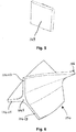
- the rotational deflector element 104 comprises a three-vaned construction as shown in FIG. 6 , comprising a central spine 104S extending generally radially outwardly from which are three deflector vanes or blades 104V1, 104V2, 104V3.
- the deflector vanes or blades 104V1, 104V2, 104V3 are equi-angularly or symmetrically positioned around the central spine 104S so they form a trio of like-shaped longitudinally extending compartments or chambers which divide up the flow of motive fluid passing through and past the deflector element 104 during its passage through the injector portion 100.
- Each deflector vane or blade 104V1, 104V2, 104V3 has a generally helical twisted shape or configuration, in order to impart a helical or twisting (or component of rotational) motion to the motive fluid as it passes thereover.
- the radial twist angle of each deflector vane or blade 104V1, 104V2, 104V3 is greater than approximately 30°, particularly in the range of from greater than about 30° up to about 90°.
- the twist angle of the deflector vanes or blades 104V1, 104V2, 104V3 may be in the region of about 50°, although twist angles of greater than 50°, e.g.
- each deflector vane or blade 104V1, 104V2, 104V3 may have a flat or bluff face, in order to increase the level of turbulence caused by the helically rotating chambers of motive fluid as they pass to the nozzle outlet 101.
- radial twist angles of the deflector vanes of the rotational deflector element may be greater than 90°, and may even be substantially greater than 90°, e.g. up to around 150 or 180 or 360 or even up to around 720°.
- Such high-twist-angle rotational deflector elements may also be usefully employed to good effect in certain alternative embodiment ejector devices within the scope of this invention.
- deflector vanes or blades 104V1, 104V2, 104V3 are shown in this illustrated embodiment, it is to be understood that any suitable number of deflector vanes or blades may be employed, e.g. 2, 3, 4 or possibly even more than 4. It may generally be preferred however that the number of deflector vanes or blades is not so high that collective frictional losses as the motive fluid passes over them become unacceptably high.
- the deflector element 104 is substantially fixed within the bore 112 of the body 110 of the injector portion 100, e.g. by being welded to or mechanically mounted onto the inner wall(s) thereof or perhaps even formed integrally therewith, so that motive fluid is caused to assume a helical motion as it passes over or through the deflector element 104 during its passage through the injector portion 100.
- the longitudinal length of the deflector element 104 is approximately equal to or less than a single diameter of the injector portion's main body 110 in which the deflector element 104 is located.
- the side-on profile of the deflector element 104 takes the form of an approximate square or rectangle. This serves to ensure that the helical rotation and resulting turbulence are applied to the motive fluid within the shortest longitudinal distance possible, whilst at the same time minimising any pressure drop over that distance.
- the efficiency improvements may be reduced owing to greater frictional losses against the surfaces of the (in that case) longer deflector vanes or blades.
- a spike element 106 Projecting from the forward end of the spine 104S of the deflector element 104, especially substantially co-axially with respect thereto, is a spike element 106 with a tapered or sharp forward tip section, which spike 106 serves to not only prevent or disrupt recirculation of motive fluid at the forward end of the deflector element 104, but also to provide a degree of pressure equalisation between the three chambers of fluid defined by the three deflector vanes or blades 104V1, 104V2, 104V3.
- a longitudinal aperture, channel or conduit may be provided extending through the axial centre of the deflector element 104, e.g.
- such a longitudinally extending channel or conduit may thus serve to guide a minor proportion of motive fluid through the deflector element 104 in addition to the major proportion thereof passing over the deflector vanes or blades 104V1, 104V2, 104V3, thereby acting in a similar or corresponding way to the spike 106 referred to above.
- the baffle plate 103 is in the form of a rectangular flat plate, e.g. of metal or other suitably strong and rigid material, which acts in conjunction with rotational deflector element 104 to modify the flow of motive fluid exiting the injector portion 100 in the novel and characteristic manner required of the present invention.
- the baffle plate 103 is positioned with its general plane parallel to the longitudinal (i.e. axial) direction of the cylindrical main body portion 110 of the injector portion 100, and so as to bisect the cross-sectional area of that cylindrical body portion 110, i.e. it divides the cross-sectional area of the cylindrical body portion 110 into two areas of substantially equal area.
- the baffle plate 103 is relatively thin, although its exact thickness may not be particularly critical, except that preferably it should generally be thick enough (e.g. dependent on the physical properties of the material from which it is formed) to withstand or resist, without deformation, non-longitudinal mechanical forces within the motive fluid flow that may tend to bend or otherwise deform it, but no more than that thickness, so that it does not unduly affect the motive fluid flow characteristics in other ways.
- the flow-modifying arrangement created thereby causes the flow of motive fluid through and along the central bore, conduit or channel 112 to separate into a plurality of discrete helical secondary flows or flow components which are contra-rotating relative to one another in a plane or respective planes perpendicular to the general longitudinal direction of motive fluid flow through the injector portion 100.
- two or more, possibly even as many as four, such discrete helical secondary flows/flow components may be generated, with adjacent ones (in a circumferential sense) being contra-rotating relative to each other.
- contra-rotating secondary flows or flow components may be of significant magnitude, such that the speed or rate of physical break-up of the overall motive fluid flow or jet as it passes through and out of the nozzle portion 102 of the injector portion 100 is markedly accelerated.
- the efficiency with which momentum and thus kinetic energy is transferred from the breaking-up motive fluid flow as it entrains the suction fluid upon exiting the injector nozzle 102 and entering the diffuser portion of the ejector device may be markedly increased, thereby leading to improved levels of compression of the suction fluid phase and thus improved pumping characteristics of the ejector device.
- FIGS. 4 and 7 show various variations in the basic constructional and spatial arrangement of the components of the novel flow modifying arrangement of the invention, which may be employed in various practical embodiments to tailor the specific motive fluid flow characteristics in order to optimise the flow modifying behaviour of the system to suit any given practical requirements.
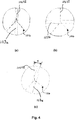
- FIGS. 4(a), (b) and (c) show three alternative embodiment arrangements in which the rotational deflector element 104 and the baffle element 103 of the injector portion 100 of the ejector device are arranged rotationally in various positions relative to each other, as follows:
- FIGS. 7(a), 7(b) and 7(c) show three yet further alternative embodiment arrangements (which may in practice optionally be combined with any of the specific embodiment arrangements shown in FIGS. 4(a) to (c) ) in which the rotational deflector element 104 and the baffle element 103 of the inlet portion 100 of the ejector device are arranged longitudinally in various positions relative to each other, possibly with variation of the internal shape of the bore 112 of the injector portion 100, as follows:
- the illustrated rotational deflector element 104 is an example of a "linear" such element, meaning that its deflector vanes or blades 104V1, 104V2, 104V3 are configured such that their twist angle varies substantially linearly with respect to the distance along the element 104 in the direction parallel to its longitudinal, i.e. axial, direction.
- the rotational deflector element may instead be substantially "non-linear” in nature, meaning that its deflector vanes or blades are configured such that their twist angle varies substantially non-linearly with respect to the distance along the element in that direction parallel to its longitudinal, i.e. axial, direction.
- An example of such a non-linear rotational deflector element 304 is illustrated in FIGS. 8(a) (in side view) and 8(b) (in isometric view).
- the deflector vanes or blades 304V1, 304V2, 304V3 are configured such that their twist angles vary substantially non-linearly - and also, by way of example, through a significantly greater twist angle than the vanes/blades in the embodiment of FIG. 6 - passing along the element 304 in the direction parallel to, especially coincident with, its longitudinal axis.
- the central spine of the element 304 terminates at its forward (downstream) end in a tapered spike element 306, which here fulfils substantially the same function as before.
- the motive pressure (Pm) defines the motive flow rate (Qm) for a given ejector design.
- the suction flow rate (Qs) is defined by the performance of the ejector design.
- the parameters Qm and Qs are calculated from readings taken from the Coriolis meters 203, 206, which measured the mass flow and temperature in the suction and motive lines.
- the performance of an ejector at a particular duty is defined as the ratio Qs/Qm (Rs) at the specified values of parameters Pm, Ps, and Pd.
- Qs/Qm the ratio of parameters at a specific duty point.
- Test piece 1 was a known ejector device employing a known injector nozzle arrangement including a conventional helical deflector element alone - as described and illustrated in our co-pending published International patent application WO 2015/189628 A1 (Transvac Systems Limited).
- Test piece 2 was an example of the new ejector device employing the novel injector arrangement, comprising helical deflector element in combination with baffle element, according to an embodiment of the present invention - as described above and illustrated in FIG. 3 of the accompanying drawings of this application.
- Each helical deflector element was 40mm in diameter in the injector portion of the ejector.
- the test comprised monitoring the critical values of the various parameters, keeping the Pm and Ps constant and changing the Pd through the full range available. This would give a value K representative of Pd - Ps.
Landscapes
- Engineering & Computer Science (AREA)
- Mechanical Engineering (AREA)
- General Engineering & Computer Science (AREA)
- Physics & Mathematics (AREA)
- Fluid Mechanics (AREA)
- Jet Pumps And Other Pumps (AREA)
Claims (15)
- Ejektorvorrichtung, die Folgendes umfasst:einen Injektorabschnitt (100), undeinen Diffusorabschnitt (50),wobei der Injektorabschnitt zum Einspritzen eines Stroms von Antriebsfluid von einem Antriebsfluideinlass in einen Einlassteilabschnitt (52) des Diffusorabschnitts angeordnet ist, um dadurch ein Saugfluid von einem Saugfluideinlass in den Einlassteilabschnitt des Diffusorabschnitts zu saugen;wobei der Injektorabschnitt (100) eine Strömungsänderungsanordnung umfasst, die Folgendes umfasst:mindestens ein Rotationsumlenkelement (104), das dazu aufgebaut und angeordnet ist, Antriebsfluid in eine schraubenförmige Bahn umzulenken, wenn es sich über oder durch das Rotationsumlenkelement bewegt, undmindestens ein Prallelement (103), das sich stromabwärts des Rotationsumlenkelements befindet,wobei mindestens ein Rotationsumlenkelement (104) bereitgestellt ist, das eine Vielzahl von schraubenförmigen Umlenkschaufeln (104V) umfasst, die dazu konfiguriert und/oder angeordnet sind, dem Antriebsfluid eine Rotationskomponente zu vermitteln, wenn es an den Schaufeln vorbeiströmt, unddadurch gekennzeichnet, dass die Strömungsänderungsanordnung des Injektorabschnitts mindestens ein Prallelement in Form einer Prallplatte (103) umfasst, wobei die Prallplatte im Wesentlichen ebenflächig ist und mit ihrer Gesamtebene im Wesentlichen parallel zu der allgemeinen Strömungsrichtung des durch den Injektorabschnitt strömenden Antriebsfluids orientiert ist.
- Ejektorvorrichtung nach Anspruch 1, wobei:(i) das Rotationsumlenkelement (104) außerdem ein sich längs erstreckendes Element, optional in Form eines Dorns (106) umfasst, das in Längsrichtung innerhalb des Injektorabschnitts von einer Verbindungstelle zwischen den jeweiligen Umlenkschaufeln vorsteht; oder(ii) das Rotationsumlenkelement außerdem eine längslaufende Öffnung, einen längslaufenden Kanal oder eine längslaufende Leitung umfasst, die bzw. der sich an einer Verbindungsstelle zwischen den jeweiligen Umlenkschaufeln oder dieser benachbart durch das Umlenkelement erstreckt.
- Ejektorvorrichtung nach Anspruch 1 oder 2, wobei die dem Antriebsfluid von dem Rotationsumlenkelement (104) vermittelte Schraubenbewegung in Form einer Spline-Linienrotation ist.
- Ejektorvorrichtung nach einem der vorangehenden Ansprüche, wobei die Prallplatte derart positioniert ist, dass sie die Querschnittsfläche des sie enthaltenden Injektorabschnitts im Wesentlichen halbiert.
- Ejektorvorrichtung nach einem der vorangehenden Ansprüche, wobei:(i) das Prallelement über sein Gesamtausmaß oder seine Gesamtrichtung im Wesentlichen ununterbrochen ist; oder(ii) das Prallelement über sein Gesamtausmaß oder seine Gesamtrichtung unterbrochen ist oder Öffnungen aufweist oder gelocht ist.
- Ejektorvorrichtung nach einem der vorangehenden Ansprüche, wobei sich das mindestens eine Prallelement (103) stromabwärts des oder des jeweiligen Rotationsumlenkelements (104) befindet und das Prallelement und das Rotationsumlenkelement derart zueinander angeordnet sind, dass ein beliebiges der Untenstehenden (i) bis (iii) gilt:(i) die Gesamtebene des Prallelements und das benachbarte oder gegenüberliegende Ende mindestens einer Umlenkschaufel des Rotationsumlenkelements im Wesentlichen miteinander fluchten oder parallel zueinander sind, oder(ii) die Gesamtebene des Prallelements und das benachbarte oder gegenüberliegende Ende mindestens einer Umlenkschaufel des Rotationsumlenkelements im Wesentlichen senkrecht zueinander sind; oder(iii) die Gesamtebene des Prallelements und das benachbarte oder gegenüberliegende Ende mindestens einer Umlenkschaufel des Rotationsumlenkelements um einen von null verschiedenen und nicht rechten Winkel relativ zueinander versetzt sind.
- Ejektorvorrichtung nach Anspruch 6, wobei:das Merkmal (i) gilt und die Gesamtebene des Prallelements und die Ebene des benachbarten oder gegenüberliegenden Endabschnitts der Umlenkschaufel des Rotationsumlenkelements in der Stirnansicht in einem Winkel von ungefähr oder im Wesentlichen 0° relativ zueinander orientiert sind; oderdas Merkmal (ii) gilt und die Gesamtebene des Prallelements und die Ebene des benachbarten oder gegenüberliegenden Endabschnitts der Umlenkschaufel des Rotationsumlenkelements in der Stirnansicht in einem Winkel von ungefähr oder im Wesentlichen 90° relativ zueinander orientiert sind; oderdas Merkmal (iii) gilt und die Gesamtebene des Prallelements und die Ebene des benachbarten oder gegenüberliegenden Endabschnitts des Umlenkflügels des Rotationsumlenkelements in der Stirnansicht in einem Winkel im ungefähren Bereich von etwa 2 oder 5 oder 10 oder 20 oder 30 oder 40° bis zu etwa 50 oder 60 oder 70 oder 80 oder 85 oder 88° relativ zueinander orientiert sind.
- Ejektorvorrichtung nach einem der vorangehenden Ansprüche wobei das Prallelement in Längsrichtung derart relativ zu dem Rotationsumlenkelement positioniert ist, dass ein beliebiges der Nachfolgenden (iv) bis (vi) gilt:(iv) das Prallelement und das Rotationsumlenkelement liegen in einer Längsrichtung im Wesentlichen aneinander an, oder(v) das Prallelement und das Rotationsumlenkelement sind in einer Längsrichtung voneinander beabstandet, oder(vi) alternativ oder zusätzlich zu einem der vorangehenden Fälle (iv) oder (v) ist mindestens eines von dem Prallelement und dem Rotationsumlenkelement, optional sowohl das Prallelement als auch das Rotationsumlenkelement, mindestens teilweise von einem Längenabschnitt des Injektorabschnitts mit gegenüber dem Rest des Injektorabschnitts verringertem Durchmesser umgeben oder im Wesentlichen darin eingeschlossen.
- Ejektorvorrichtung nach Anspruch 8, wobei das Merkmal (v) gilt und der relative Längsabstand zwischen dem Prallelement und dem Rotationsumlenkelement ausgewählt ist, um von etwa 1 oder 2 oder 5 oder 10 oder 20 % bis zu etwa 50 oder 60 oder 70 oder 80 oder 90 oder 100% der Länge in Längsrichtung des Rotationsumlenkelements selbst zu betragen.
- Ejektorvorrichtung nach einem der vorangehenden Ansprüche, wobei sich das Prallelement (103) in dem Injektorabschnitt (100) entweder:(i) mindestens teilweise innerhalb, oder(ii) unmittelbar stromaufwärts eines konvergierenden Düsenabschnitts (102) des Einlassabschnitts der Ejektorvorrichtung befindet.
- Ejektorvorrichtung nach einem der vorangehenden Ansprüche, wobei das mindestens eine Rotationsumlenkelement (104) eines der Folgenden umfasst:(i) ein lineares Rotationsumlenkelement, bei dem sich der Drallwinkel seiner Umlenkschaufeln in Bezug auf die Strecke daran entlang in der der zu der Längsrichtung des Rotationsumlenkelements parallelen Richtung im Wesentlichen linear ändert; oder(ii) ein nichtlineares Rotationsumlenkelement, bei dem sich der Drallwinkel seiner Umlenkschaufeln in Bezug auf die Strecke daran entlang in der der zu der Längsrichtung des Rotationsumlenkelements parallelen Richtung im Wesentlichen nichtlinear ändert.
- Ejektorvorrichtung nach einem der vorangehenden Ansprüche, wobei die Strömungsänderungsanordnung innerhalb des Injektorabschnitts (100) der Ejektorvorrichtung dazu aufgebaut, konfiguriert und angeordnet ist, in dem Antriebsfluid, wenn es aus dem Injektorabschnitt austritt, mindestens zwei oder eine Vielzahl von Sekundärströmungen oder Sekundärströmungskomponenten zu erzeugen, die in einer Ebene oder jeweiligen Ebenen, die allgemein zu der allgemeinen Längsrichtung von Antriebsfluid, wenn es durch den Injektorabschnitt der Vorrichtung strömt, ungefähr oder im Wesentlichen senkrecht oder quer sind, relativ zueinander gegenläufig rotieren.
- Injektoranordnung zur Verwendung in einer Ejektoranordnung nach einem der vorangehenden Ansprüche oder wenn darin verwendet, wobei die Ejektorvorrichtung die Injektoranordnung und den Diffusorabschnitt umfasst.
- Pumpvorrichtung, die eine Ejektorvorrichtung nach einem der Ansprüche 1 bis 12 umfasst.
- Verfahren zum Pumpen eines Fluids, wobei es sich bei dem zu pumpenden Fluid um ein Saugfluid, vorzugsweise in der Gasphase, handelt, wobei das Verfahren Folgendes umfasst:Bereitstellen einer Ejektorvorrichtung nach einem der Ansprüche 1 bis 12;Bereitstellen einer Zufuhr von Antriebsfluid, vorzugsweise in der Flüssigphase;Einspritzen, mittels des Injektorabschnitts der Vorrichtung, eines Stroms des Antriebsfluids von dem Antriebsfluideinlass in den Einlassteilabschnitt des Diffusorabschnitts, wodurch Saugfluid von dem Saugfluideinlass in den Einlassteilabschnitt des Diffusorabschnitts gesaugt wird und mit dem eingespritzten Antriebsfluid gemischt wird; undLeiten des gemischten Antriebsfluids und Saugfluids durch den Diffusorabschnitt und Ausstoßen des gemischten Antriebsfluids und Saugfluids aus der Ejektorvorrichtung über einen gemeinsamen Auslass derselben;wobei, wenn das Antriebsfluid aus dem Injektorabschnitt austritt, es durch die Strömungsänderungsanordnung strömt, die das mindestens eine Rotationsumlenkelement (104) und das mindestens eine Prallelement (103) umfasst.
Applications Claiming Priority (2)
| Application Number | Priority Date | Filing Date | Title |
|---|---|---|---|
| GB1700463.1A GB2558627B (en) | 2017-01-11 | 2017-01-11 | Ejector device |
| PCT/GB2018/050042 WO2018130818A1 (en) | 2017-01-11 | 2018-01-09 | Ejector device |
Publications (2)
| Publication Number | Publication Date |
|---|---|
| EP3568599A1 EP3568599A1 (de) | 2019-11-20 |
| EP3568599B1 true EP3568599B1 (de) | 2021-05-19 |
Family
ID=58463862
Family Applications (1)
| Application Number | Title | Priority Date | Filing Date |
|---|---|---|---|
| EP18700802.4A Active EP3568599B1 (de) | 2017-01-11 | 2018-01-09 | Ejektor |
Country Status (5)
| Country | Link |
|---|---|
| US (1) | US11274680B2 (de) |
| EP (1) | EP3568599B1 (de) |
| GB (1) | GB2558627B (de) |
| SA (1) | SA519402315B1 (de) |
| WO (1) | WO2018130818A1 (de) |
Cited By (1)
| Publication number | Priority date | Publication date | Assignee | Title |
|---|---|---|---|---|
| US11274680B2 (en) | 2017-01-11 | 2022-03-15 | Transvac Systems Limited | Ejector device |
Families Citing this family (5)
| Publication number | Priority date | Publication date | Assignee | Title |
|---|---|---|---|---|
| EP3099987B1 (de) * | 2014-01-30 | 2022-07-20 | Carrier Corporation | Ejektor und verfahren zur herstellung dafür |
| FR3050778B1 (fr) * | 2016-04-27 | 2020-02-14 | Safran Aircraft Engines | Pompe a jet pour turbomachine, comprenant un aubage pour mise en rotation de fluide actif |
| GB201916064D0 (en) | 2019-11-05 | 2019-12-18 | Transvac Systems Ltd | Ejector device |
| JP7490945B2 (ja) * | 2019-11-06 | 2024-05-28 | 富士電機株式会社 | エジェクタ |
| US11835183B1 (en) | 2023-02-01 | 2023-12-05 | Flowserve Management Company | Booster-ejector system for capturing and recycling leakage fluids |
Family Cites Families (29)
| Publication number | Priority date | Publication date | Assignee | Title |
|---|---|---|---|---|
| US92313A (en) * | 1869-07-06 | Christian hughes | ||
| US541781A (en) * | 1895-06-25 | The geo | ||
| US857920A (en) | 1906-11-22 | 1907-06-25 | Julius Boekel | Aspirator. |
| GB197684A (en) * | 1922-05-10 | 1924-03-27 | Adolf Martin Kobiolke | An improved vacuum producing device |
| US1739600A (en) * | 1926-07-09 | 1929-12-17 | Loth William Arthur | Apparatus for producing variations of pressure |
| US2804341A (en) * | 1956-04-13 | 1957-08-27 | Bete Fog Nozzle Inc | Spray nozzles |
| US3134338A (en) * | 1961-08-07 | 1964-05-26 | A Y Dodge Co | Jet pump |
| US3277660A (en) * | 1965-12-13 | 1966-10-11 | Kaye & Co Inc Joseph | Multiple-phase ejector refrigeration system |
| US3662960A (en) * | 1966-11-21 | 1972-05-16 | United Aircraft Corp | Injector head |
| DE1941993B2 (de) * | 1969-08-18 | 1972-03-23 | Vorrichtung zum einspuelen von bauelementen | |
| US3680793A (en) * | 1970-11-09 | 1972-08-01 | Delavan Manufacturing Co | Eccentric spiral swirl chamber nozzle |
| DE2410570C2 (de) * | 1974-03-06 | 1982-04-29 | Basf Ag, 6700 Ludwigshafen | Vorrichtung zum Ansaugen und Verdichten von Gasen und deren Vermischung mit Flüssigkeit |
| DE2634496C2 (de) * | 1976-07-31 | 1985-10-17 | Bayer Ag, 5090 Leverkusen | Injektor zur Begasung einer Flüssigkeit |
| US4834132A (en) * | 1986-09-25 | 1989-05-30 | Nissan Motor Company, Limited | Fuel transfer apparatus |
| JP2598091B2 (ja) * | 1988-07-15 | 1997-04-09 | 日産自動車株式会社 | 燃料タンクの燃料吸込装置 |
| US5322222A (en) * | 1992-10-05 | 1994-06-21 | Lott W Gerald | Spiral jet fluid mixer |
| JPH07117080A (ja) * | 1993-10-27 | 1995-05-09 | Sekisui Chem Co Ltd | 射出成形金型及び成形体の製造方法 |
| US5454696A (en) * | 1994-06-27 | 1995-10-03 | Wilkinson; Ernest H. | Vacuum inducing pump |
| FR2787838B1 (fr) * | 1998-12-23 | 2002-01-11 | Inst Francais Du Petrole | Dispositif de pompage a jet |
| GB2384027B (en) | 2002-01-11 | 2006-04-12 | Transvac Systems Ltd | Ejector |
| WO2010083151A2 (en) * | 2009-01-13 | 2010-07-22 | Avl North America Inc. | Ejector type egr mixer |
| US8807458B2 (en) * | 2009-04-29 | 2014-08-19 | King Saud University | Vortex-generating nozzle-end ring |
| US9242260B2 (en) * | 2010-04-01 | 2016-01-26 | Proven Technologies, Llc | Directed multiport eductor and method of use |
| GB201018721D0 (en) * | 2010-11-05 | 2010-12-22 | Transvac Systems Ltd | Improved ejector and method |
| US8622715B1 (en) * | 2011-12-21 | 2014-01-07 | Compatible Components Corporation | Twin turbine asymmetrical nozzle and jet pump incorporating such nozzle |
| JP6119566B2 (ja) * | 2012-12-27 | 2017-04-26 | 株式会社デンソー | エジェクタ |
| GB2524820A (en) * | 2014-04-04 | 2015-10-07 | Caltec Ltd | Jet pump |
| GB2527096A (en) * | 2014-06-11 | 2015-12-16 | Transvac Systems Ltd | Ejector device and method |
| GB2558627B (en) | 2017-01-11 | 2020-02-26 | Transvac Systems Ltd | Ejector device |
-
2017
- 2017-01-11 GB GB1700463.1A patent/GB2558627B/en active Active
-
2018
- 2018-01-09 WO PCT/GB2018/050042 patent/WO2018130818A1/en not_active Ceased
- 2018-01-09 EP EP18700802.4A patent/EP3568599B1/de active Active
- 2018-01-09 US US16/476,931 patent/US11274680B2/en active Active
-
2019
- 2019-07-11 SA SA519402315A patent/SA519402315B1/ar unknown
Non-Patent Citations (1)
| Title |
|---|
| None * |
Cited By (1)
| Publication number | Priority date | Publication date | Assignee | Title |
|---|---|---|---|---|
| US11274680B2 (en) | 2017-01-11 | 2022-03-15 | Transvac Systems Limited | Ejector device |
Also Published As
| Publication number | Publication date |
|---|---|
| EP3568599A1 (de) | 2019-11-20 |
| US11274680B2 (en) | 2022-03-15 |
| SA519402315B1 (ar) | 2022-09-13 |
| WO2018130818A1 (en) | 2018-07-19 |
| US20190331139A1 (en) | 2019-10-31 |
| GB201700463D0 (en) | 2017-02-22 |
| GB2558627A (en) | 2018-07-18 |
| GB2558627B (en) | 2020-02-26 |
Similar Documents
| Publication | Publication Date | Title |
|---|---|---|
| US11274680B2 (en) | Ejector device | |
| WO2015189628A1 (en) | Ejector device and method | |
| US10578110B2 (en) | Centrifugal pump with coalescing effect, design method and use thereof | |
| CN105909567B (zh) | 一种改善射流式离心泵空化性能的射流器 | |
| EP2529843A2 (de) | Rückflussdüse zur Erzeugung einer Kavitation oder Impulsstrahlen | |
| EP2635816B1 (de) | Ejektor und verfahren | |
| JP4426612B2 (ja) | 微細気泡発生ノズル | |
| CN106660842A (zh) | 微气泡喷嘴 | |
| JP2007021343A (ja) | マイクロバブル発生装置 | |
| WO2019162649A1 (en) | Jet pump apparatus | |
| JP4966873B2 (ja) | ジェットポンプ及び原子炉 | |
| EP4055277B1 (de) | Ejektor | |
| WO1999054629A1 (fr) | Appareil a jets de gaz et de liquides et variantes | |
| RU2158627C1 (ru) | Смеситель кавитационного типа | |
| CN205744629U (zh) | 一种改善射流式离心泵空化性能的射流器 | |
| JP6593610B2 (ja) | 混気用ノズル | |
| RU2374971C1 (ru) | Трубочка для питья | |
| RU2072454C1 (ru) | Жидкостно-газовый эжектор | |
| JP2017155621A (ja) | エジェクタ | |
| RU2142070C1 (ru) | Жидкостно-газовый эжектор | |
| RU70696U1 (ru) | Жидкостно-газовый эжектор | |
| Green | Jet pumps and ejectors | |
| CN223875677U (zh) | 一种微纳米气泡发生装置及清洗设备 | |
| CN110170258A (zh) | 气液混合增压装置 | |
| RU2133884C1 (ru) | Жидкостно-газовый эжектор (варианты) |
Legal Events
| Date | Code | Title | Description |
|---|---|---|---|
| STAA | Information on the status of an ep patent application or granted ep patent |
Free format text: STATUS: UNKNOWN |
|
| STAA | Information on the status of an ep patent application or granted ep patent |
Free format text: STATUS: THE INTERNATIONAL PUBLICATION HAS BEEN MADE |
|
| PUAI | Public reference made under article 153(3) epc to a published international application that has entered the european phase |
Free format text: ORIGINAL CODE: 0009012 |
|
| STAA | Information on the status of an ep patent application or granted ep patent |
Free format text: STATUS: REQUEST FOR EXAMINATION WAS MADE |
|
| 17P | Request for examination filed |
Effective date: 20190802 |
|
| AK | Designated contracting states |
Kind code of ref document: A1 Designated state(s): AL AT BE BG CH CY CZ DE DK EE ES FI FR GB GR HR HU IE IS IT LI LT LU LV MC MK MT NL NO PL PT RO RS SE SI SK SM TR |
|
| AX | Request for extension of the european patent |
Extension state: BA ME |
|
| DAV | Request for validation of the european patent (deleted) | ||
| DAX | Request for extension of the european patent (deleted) | ||
| GRAP | Despatch of communication of intention to grant a patent |
Free format text: ORIGINAL CODE: EPIDOSNIGR1 |
|
| STAA | Information on the status of an ep patent application or granted ep patent |
Free format text: STATUS: GRANT OF PATENT IS INTENDED |
|
| INTG | Intention to grant announced |
Effective date: 20200713 |
|
| GRAJ | Information related to disapproval of communication of intention to grant by the applicant or resumption of examination proceedings by the epo deleted |
Free format text: ORIGINAL CODE: EPIDOSDIGR1 |
|
| STAA | Information on the status of an ep patent application or granted ep patent |
Free format text: STATUS: REQUEST FOR EXAMINATION WAS MADE |
|
| GRAP | Despatch of communication of intention to grant a patent |
Free format text: ORIGINAL CODE: EPIDOSNIGR1 |
|
| STAA | Information on the status of an ep patent application or granted ep patent |
Free format text: STATUS: GRANT OF PATENT IS INTENDED |
|
| INTC | Intention to grant announced (deleted) | ||
| INTG | Intention to grant announced |
Effective date: 20201211 |
|
| GRAS | Grant fee paid |
Free format text: ORIGINAL CODE: EPIDOSNIGR3 |
|
| GRAA | (expected) grant |
Free format text: ORIGINAL CODE: 0009210 |
|
| STAA | Information on the status of an ep patent application or granted ep patent |
Free format text: STATUS: THE PATENT HAS BEEN GRANTED |
|
| AK | Designated contracting states |
Kind code of ref document: B1 Designated state(s): AL AT BE BG CH CY CZ DE DK EE ES FI FR GR HR HU IE IS IT LI LT LU LV MC MK MT NL NO PL PT RO RS SE SI SK SM TR |
|
| RBV | Designated contracting states (corrected) |
Designated state(s): AL AT BE BG CH CY CZ DE DK EE ES FI FR GR HR HU IE IS IT LI LT LU LV MC MK MT NL NO PL PT RO RS SE SI SK SM TR |
|
| REG | Reference to a national code |
Ref country code: CH Ref legal event code: EP |
|
| REG | Reference to a national code |
Ref country code: DE Ref legal event code: R096 Ref document number: 602018017262 Country of ref document: DE |
|
| REG | Reference to a national code |
Ref country code: AT Ref legal event code: REF Ref document number: 1394248 Country of ref document: AT Kind code of ref document: T Effective date: 20210615 |
|
| REG | Reference to a national code |
Ref country code: IE Ref legal event code: FG4D |
|
| REG | Reference to a national code |
Ref country code: NL Ref legal event code: FP |
|
| REG | Reference to a national code |
Ref country code: NO Ref legal event code: T2 Effective date: 20210519 |
|
| REG | Reference to a national code |
Ref country code: LT Ref legal event code: MG9D |
|
| REG | Reference to a national code |
Ref country code: AT Ref legal event code: MK05 Ref document number: 1394248 Country of ref document: AT Kind code of ref document: T Effective date: 20210519 |
|
| PG25 | Lapsed in a contracting state [announced via postgrant information from national office to epo] |
Ref country code: FI Free format text: LAPSE BECAUSE OF FAILURE TO SUBMIT A TRANSLATION OF THE DESCRIPTION OR TO PAY THE FEE WITHIN THE PRESCRIBED TIME-LIMIT Effective date: 20210519 Ref country code: HR Free format text: LAPSE BECAUSE OF FAILURE TO SUBMIT A TRANSLATION OF THE DESCRIPTION OR TO PAY THE FEE WITHIN THE PRESCRIBED TIME-LIMIT Effective date: 20210519 Ref country code: LT Free format text: LAPSE BECAUSE OF FAILURE TO SUBMIT A TRANSLATION OF THE DESCRIPTION OR TO PAY THE FEE WITHIN THE PRESCRIBED TIME-LIMIT Effective date: 20210519 Ref country code: AT Free format text: LAPSE BECAUSE OF FAILURE TO SUBMIT A TRANSLATION OF THE DESCRIPTION OR TO PAY THE FEE WITHIN THE PRESCRIBED TIME-LIMIT Effective date: 20210519 Ref country code: BG Free format text: LAPSE BECAUSE OF FAILURE TO SUBMIT A TRANSLATION OF THE DESCRIPTION OR TO PAY THE FEE WITHIN THE PRESCRIBED TIME-LIMIT Effective date: 20210819 |
|
| PG25 | Lapsed in a contracting state [announced via postgrant information from national office to epo] |
Ref country code: LV Free format text: LAPSE BECAUSE OF FAILURE TO SUBMIT A TRANSLATION OF THE DESCRIPTION OR TO PAY THE FEE WITHIN THE PRESCRIBED TIME-LIMIT Effective date: 20210519 Ref country code: PT Free format text: LAPSE BECAUSE OF FAILURE TO SUBMIT A TRANSLATION OF THE DESCRIPTION OR TO PAY THE FEE WITHIN THE PRESCRIBED TIME-LIMIT Effective date: 20210920 Ref country code: PL Free format text: LAPSE BECAUSE OF FAILURE TO SUBMIT A TRANSLATION OF THE DESCRIPTION OR TO PAY THE FEE WITHIN THE PRESCRIBED TIME-LIMIT Effective date: 20210519 Ref country code: RS Free format text: LAPSE BECAUSE OF FAILURE TO SUBMIT A TRANSLATION OF THE DESCRIPTION OR TO PAY THE FEE WITHIN THE PRESCRIBED TIME-LIMIT Effective date: 20210519 Ref country code: SE Free format text: LAPSE BECAUSE OF FAILURE TO SUBMIT A TRANSLATION OF THE DESCRIPTION OR TO PAY THE FEE WITHIN THE PRESCRIBED TIME-LIMIT Effective date: 20210519 Ref country code: GR Free format text: LAPSE BECAUSE OF FAILURE TO SUBMIT A TRANSLATION OF THE DESCRIPTION OR TO PAY THE FEE WITHIN THE PRESCRIBED TIME-LIMIT Effective date: 20210820 Ref country code: IS Free format text: LAPSE BECAUSE OF FAILURE TO SUBMIT A TRANSLATION OF THE DESCRIPTION OR TO PAY THE FEE WITHIN THE PRESCRIBED TIME-LIMIT Effective date: 20210919 |
|
| PG25 | Lapsed in a contracting state [announced via postgrant information from national office to epo] |
Ref country code: SK Free format text: LAPSE BECAUSE OF FAILURE TO SUBMIT A TRANSLATION OF THE DESCRIPTION OR TO PAY THE FEE WITHIN THE PRESCRIBED TIME-LIMIT Effective date: 20210519 Ref country code: SM Free format text: LAPSE BECAUSE OF FAILURE TO SUBMIT A TRANSLATION OF THE DESCRIPTION OR TO PAY THE FEE WITHIN THE PRESCRIBED TIME-LIMIT Effective date: 20210519 Ref country code: ES Free format text: LAPSE BECAUSE OF FAILURE TO SUBMIT A TRANSLATION OF THE DESCRIPTION OR TO PAY THE FEE WITHIN THE PRESCRIBED TIME-LIMIT Effective date: 20210519 Ref country code: EE Free format text: LAPSE BECAUSE OF FAILURE TO SUBMIT A TRANSLATION OF THE DESCRIPTION OR TO PAY THE FEE WITHIN THE PRESCRIBED TIME-LIMIT Effective date: 20210519 Ref country code: RO Free format text: LAPSE BECAUSE OF FAILURE TO SUBMIT A TRANSLATION OF THE DESCRIPTION OR TO PAY THE FEE WITHIN THE PRESCRIBED TIME-LIMIT Effective date: 20210519 Ref country code: DK Free format text: LAPSE BECAUSE OF FAILURE TO SUBMIT A TRANSLATION OF THE DESCRIPTION OR TO PAY THE FEE WITHIN THE PRESCRIBED TIME-LIMIT Effective date: 20210519 Ref country code: CZ Free format text: LAPSE BECAUSE OF FAILURE TO SUBMIT A TRANSLATION OF THE DESCRIPTION OR TO PAY THE FEE WITHIN THE PRESCRIBED TIME-LIMIT Effective date: 20210519 |
|
| REG | Reference to a national code |
Ref country code: DE Ref legal event code: R097 Ref document number: 602018017262 Country of ref document: DE |
|
| PLBE | No opposition filed within time limit |
Free format text: ORIGINAL CODE: 0009261 |
|
| STAA | Information on the status of an ep patent application or granted ep patent |
Free format text: STATUS: NO OPPOSITION FILED WITHIN TIME LIMIT |
|
| 26N | No opposition filed |
Effective date: 20220222 |
|
| PG25 | Lapsed in a contracting state [announced via postgrant information from national office to epo] |
Ref country code: IS Free format text: LAPSE BECAUSE OF FAILURE TO SUBMIT A TRANSLATION OF THE DESCRIPTION OR TO PAY THE FEE WITHIN THE PRESCRIBED TIME-LIMIT Effective date: 20210919 Ref country code: AL Free format text: LAPSE BECAUSE OF FAILURE TO SUBMIT A TRANSLATION OF THE DESCRIPTION OR TO PAY THE FEE WITHIN THE PRESCRIBED TIME-LIMIT Effective date: 20210519 |
|
| PG25 | Lapsed in a contracting state [announced via postgrant information from national office to epo] |
Ref country code: IT Free format text: LAPSE BECAUSE OF FAILURE TO SUBMIT A TRANSLATION OF THE DESCRIPTION OR TO PAY THE FEE WITHIN THE PRESCRIBED TIME-LIMIT Effective date: 20210519 |
|
| PG25 | Lapsed in a contracting state [announced via postgrant information from national office to epo] |
Ref country code: MC Free format text: LAPSE BECAUSE OF FAILURE TO SUBMIT A TRANSLATION OF THE DESCRIPTION OR TO PAY THE FEE WITHIN THE PRESCRIBED TIME-LIMIT Effective date: 20210519 |
|
| REG | Reference to a national code |
Ref country code: CH Ref legal event code: PL |
|
| REG | Reference to a national code |
Ref country code: BE Ref legal event code: MM Effective date: 20220131 |
|
| PG25 | Lapsed in a contracting state [announced via postgrant information from national office to epo] |
Ref country code: LU Free format text: LAPSE BECAUSE OF NON-PAYMENT OF DUE FEES Effective date: 20220109 |
|
| PG25 | Lapsed in a contracting state [announced via postgrant information from national office to epo] |
Ref country code: BE Free format text: LAPSE BECAUSE OF NON-PAYMENT OF DUE FEES Effective date: 20220131 |
|
| PG25 | Lapsed in a contracting state [announced via postgrant information from national office to epo] |
Ref country code: LI Free format text: LAPSE BECAUSE OF NON-PAYMENT OF DUE FEES Effective date: 20220131 Ref country code: CH Free format text: LAPSE BECAUSE OF NON-PAYMENT OF DUE FEES Effective date: 20220131 |
|
| PG25 | Lapsed in a contracting state [announced via postgrant information from national office to epo] |
Ref country code: IE Free format text: LAPSE BECAUSE OF NON-PAYMENT OF DUE FEES Effective date: 20220109 |
|
| PG25 | Lapsed in a contracting state [announced via postgrant information from national office to epo] |
Ref country code: MK Free format text: LAPSE BECAUSE OF FAILURE TO SUBMIT A TRANSLATION OF THE DESCRIPTION OR TO PAY THE FEE WITHIN THE PRESCRIBED TIME-LIMIT Effective date: 20210519 Ref country code: CY Free format text: LAPSE BECAUSE OF FAILURE TO SUBMIT A TRANSLATION OF THE DESCRIPTION OR TO PAY THE FEE WITHIN THE PRESCRIBED TIME-LIMIT Effective date: 20210519 |
|
| PG25 | Lapsed in a contracting state [announced via postgrant information from national office to epo] |
Ref country code: HU Free format text: LAPSE BECAUSE OF FAILURE TO SUBMIT A TRANSLATION OF THE DESCRIPTION OR TO PAY THE FEE WITHIN THE PRESCRIBED TIME-LIMIT; INVALID AB INITIO Effective date: 20180109 |
|
| PG25 | Lapsed in a contracting state [announced via postgrant information from national office to epo] |
Ref country code: MT Free format text: LAPSE BECAUSE OF FAILURE TO SUBMIT A TRANSLATION OF THE DESCRIPTION OR TO PAY THE FEE WITHIN THE PRESCRIBED TIME-LIMIT Effective date: 20210519 |
|
| PG25 | Lapsed in a contracting state [announced via postgrant information from national office to epo] |
Ref country code: TR Free format text: LAPSE BECAUSE OF FAILURE TO SUBMIT A TRANSLATION OF THE DESCRIPTION OR TO PAY THE FEE WITHIN THE PRESCRIBED TIME-LIMIT Effective date: 20210519 |
|
| PGFP | Annual fee paid to national office [announced via postgrant information from national office to epo] |
Ref country code: NL Payment date: 20260121 Year of fee payment: 9 |
|
| PGFP | Annual fee paid to national office [announced via postgrant information from national office to epo] |
Ref country code: NO Payment date: 20260123 Year of fee payment: 9 Ref country code: DE Payment date: 20260121 Year of fee payment: 9 |
|
| PGFP | Annual fee paid to national office [announced via postgrant information from national office to epo] |
Ref country code: FR Payment date: 20260123 Year of fee payment: 9 |