EP3568096B1 - Verstellbare rippe und sternumimplantat - Google Patents
Verstellbare rippe und sternumimplantat Download PDFInfo
- Publication number
- EP3568096B1 EP3568096B1 EP17817371.2A EP17817371A EP3568096B1 EP 3568096 B1 EP3568096 B1 EP 3568096B1 EP 17817371 A EP17817371 A EP 17817371A EP 3568096 B1 EP3568096 B1 EP 3568096B1
- Authority
- EP
- European Patent Office
- Prior art keywords
- rib
- implant
- matrix
- bores
- sternal
- Prior art date
- Legal status (The legal status is an assumption and is not a legal conclusion. Google has not performed a legal analysis and makes no representation as to the accuracy of the status listed.)
- Active
Links
Images


Classifications
-
- A—HUMAN NECESSITIES
- A61—MEDICAL OR VETERINARY SCIENCE; HYGIENE
- A61B—DIAGNOSIS; SURGERY; IDENTIFICATION
- A61B17/00—Surgical instruments, devices or methods
- A61B17/56—Surgical instruments or methods for treatment of bones or joints; Devices specially adapted therefor
- A61B17/58—Surgical instruments or methods for treatment of bones or joints; Devices specially adapted therefor for osteosynthesis, e.g. bone plates, screws or setting implements
- A61B17/68—Internal fixation devices, including fasteners and spinal fixators, even if a part thereof projects from the skin
- A61B17/80—Cortical plates, i.e. bone plates; Instruments for holding or positioning cortical plates, or for compressing bones attached to cortical plates
- A61B17/8061—Cortical plates, i.e. bone plates; Instruments for holding or positioning cortical plates, or for compressing bones attached to cortical plates specially adapted for particular bones
- A61B17/8076—Cortical plates, i.e. bone plates; Instruments for holding or positioning cortical plates, or for compressing bones attached to cortical plates specially adapted for particular bones for the ribs or the sternum
-
- A—HUMAN NECESSITIES
- A61—MEDICAL OR VETERINARY SCIENCE; HYGIENE
- A61B—DIAGNOSIS; SURGERY; IDENTIFICATION
- A61B17/00—Surgical instruments, devices or methods
- A61B17/56—Surgical instruments or methods for treatment of bones or joints; Devices specially adapted therefor
- A61B17/58—Surgical instruments or methods for treatment of bones or joints; Devices specially adapted therefor for osteosynthesis, e.g. bone plates, screws or setting implements
- A61B17/68—Internal fixation devices, including fasteners and spinal fixators, even if a part thereof projects from the skin
- A61B17/80—Cortical plates, i.e. bone plates; Instruments for holding or positioning cortical plates, or for compressing bones attached to cortical plates
- A61B17/8023—Variable length plates adjustable in both directions
-
- A—HUMAN NECESSITIES
- A61—MEDICAL OR VETERINARY SCIENCE; HYGIENE
- A61B—DIAGNOSIS; SURGERY; IDENTIFICATION
- A61B17/00—Surgical instruments, devices or methods
- A61B17/04—Surgical instruments, devices or methods for suturing wounds; Holders or packages for needles or suture materials
- A61B17/0401—Suture anchors, buttons or pledgets, i.e. means for attaching sutures to bone, cartilage or soft tissue; Instruments for applying or removing suture anchors
- A61B2017/0414—Suture anchors, buttons or pledgets, i.e. means for attaching sutures to bone, cartilage or soft tissue; Instruments for applying or removing suture anchors having a suture-receiving opening, e.g. lateral opening
-
- A—HUMAN NECESSITIES
- A61—MEDICAL OR VETERINARY SCIENCE; HYGIENE
- A61B—DIAGNOSIS; SURGERY; IDENTIFICATION
- A61B17/00—Surgical instruments, devices or methods
- A61B17/04—Surgical instruments, devices or methods for suturing wounds; Holders or packages for needles or suture materials
- A61B17/0401—Suture anchors, buttons or pledgets, i.e. means for attaching sutures to bone, cartilage or soft tissue; Instruments for applying or removing suture anchors
- A61B2017/0464—Suture anchors, buttons or pledgets, i.e. means for attaching sutures to bone, cartilage or soft tissue; Instruments for applying or removing suture anchors for soft tissue
-
- A—HUMAN NECESSITIES
- A61—MEDICAL OR VETERINARY SCIENCE; HYGIENE
- A61B—DIAGNOSIS; SURGERY; IDENTIFICATION
- A61B34/00—Computer-aided surgery; Manipulators or robots specially adapted for use in surgery
- A61B34/10—Computer-aided planning, simulation or modelling of surgical operations
- A61B2034/108—Computer aided selection or customisation of medical implants or cutting guides
-
- A—HUMAN NECESSITIES
- A61—MEDICAL OR VETERINARY SCIENCE; HYGIENE
- A61F—FILTERS IMPLANTABLE INTO BLOOD VESSELS; PROSTHESES; DEVICES PROVIDING PATENCY TO, OR PREVENTING COLLAPSING OF, TUBULAR STRUCTURES OF THE BODY, e.g. STENTS; ORTHOPAEDIC, NURSING OR CONTRACEPTIVE DEVICES; FOMENTATION; TREATMENT OR PROTECTION OF EYES OR EARS; BANDAGES, DRESSINGS OR ABSORBENT PADS; FIRST-AID KITS
- A61F2/00—Filters implantable into blood vessels; Prostheses, i.e. artificial substitutes or replacements for parts of the body; Appliances for connecting them with the body; Devices providing patency to, or preventing collapsing of, tubular structures of the body, e.g. stents
- A61F2/02—Prostheses implantable into the body
- A61F2/08—Muscles; Tendons; Ligaments
- A61F2/0811—Fixation devices for tendons or ligaments
- A61F2002/0817—Structure of the anchor
- A61F2002/0823—Modular anchors comprising a plurality of separate parts
- A61F2002/0829—Modular anchors comprising a plurality of separate parts without deformation of anchor parts, e.g. fixation screws on bone surface, extending barbs, cams, butterflies, spring-loaded pins
Definitions
- surgeons For patients with a sternal tumor, congenital sternal disorder, or various sternal injuries surgeons sometimes remove an affected sternum or sternal portion. Depending on the location and size of the tumor, adjoining rib segments can be disconnected from the sternum as part of the procedure. For regaining the anatomical integrity between the sternum and rib cage and for protecting the organs that are directly behind the sternum, surgeons can use a muscle flap to provide coverage and protection of the affected rib segments and sternum. In cases where a large section or the total sternum is removed, these muscle flaps may not offer the protection and support needed for maintaining the anatomical integrity.
- FR3004337 relates to a prosthetic sternum device comprising a plate and means for securing to the ribs, each of said means for securing to the ribs comprising a means for attaching to a rib and a means for fastening to the plate, said plate comprising, to this end, a plurality of zones for fastening one of the attachment means, distributed around the periphery.
- the implant can include removable rib links that are individually couplable to ribs.
- the implant can also include superior bores for securing the sternal implant to remaining sternum bone and/or manubrium.
- the implant can also include cartilage connectors for securing the implant to costal cartilage. This design can provide structural rigidity and organ protection not provided by a muscle flap method. This design can also provide flexibility, adaptability, and modularity not provided by a single-plate method.
- the present ap plication relates to devices and sy stems for sternal replacement procedures.
- the present application discloses a sternal and rib implant system configured to secure to a sternum, manubrium, and/or ribs of a patient. Details are discussed further below.
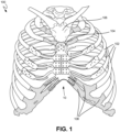
- FIG. 1 shows an isometric view of implant 10 secured to rib cage 100 of a patient, in accordance with an example of the present disclosure.
- Rib cage 100 generally includes ribs 102, sternum (or body) 104, manubrium (or upper sternum) 106, and cartilage (or costal cartilage) 108.
- Rib cage 100 generally includes other components not labeled or shown, such as a xyphoid process.
- a sternum such as sternum 100 can become compromised, such as with a tumor.
- the sternum, manubrium, xyphoid process, ribs, and/or cartilage may need to be removed or disconnected by a surgeon.
- implant 10 can be used to replace the removed structural components, such as sternum 104 and manubrium 106.
- implant 10 can be a sternal implant coupled to a resected or partial sternum 104 and/or manubrium 106 at a sup erior portion and coupled to cartilage 108 at an inferior and/or distal portion, or at any location of a patient where cartilage is present in a patient.
- Implant 10 can also include rib links coup led to a matrix of the implant, where the rib links can be further coupled to ribs 102.
- implant 10 can provide some of the structure and functions lost as a result of resecting or removing sternum 104, manubrium 106, and/or ribs 102, such as protecting vital organs.
- implant 10 provides the benefit of modularity as rib links can be installed in many configurations.
- Implant 10 also offers the benefit of customization, as implant 10 can be patient-matched in many ways. These details and more are discussed further below.
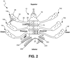
- FIG. 2 shows an isometric view of implant 10 from an anterior perspective.
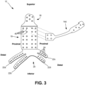
- FIG. 3 shows an isometric view of implant 10 with rib links removed. FIGS. 2 and 3 are discussed concurrently.
- Implant 10 can include sternal implant 12, rib links 14a, 14b, 14c, 14d, 14e, and 14f, and fasteners 16.
- Sternal implant 12 can include superior portion 18, matrix 19, and inferior portion 20.
- Inferior portion 20 can include cartilage links 22a, 22b, 22c, and 22d, which can each include suture bores 24.
- Superior portion can include superior bores 26.
- Each of rib links 14a-14f can include proximal portion 28, strut 30, and distal portion 32.
- Each of proximal portions 28 can include proximal bores 34.
- Each of distal portions 32 can include distal bores 36, and alignment tabs 38.
- Matrix 19 can include matrix bores 40.
- Fasteners 16 can include cap 42 in some examples and can include tang 44 in some other examples. Also shown in FIGS. 2 and 3 are orientation identifiers superior, inferior, proximal, and distal.
- Sternal implant 12 and rib links 14 can be comprised of a rigid material, such as any material suitable for implant in a human body, for example, stainless steel alloys, titanium alloys, polyetherketoneketone(PEKK), and cobalt/chromium alloys.
- sternal implant 12 and rib link 14 can be comprised of titanium 6A1-4V.
- Sternal implant 12 can be of a geometric shape of a sternum and/or a manubrium.
- sternal implant 12 can have a shape that is matched to a native anatomy, such as a sternum, of a patient. This can improve the overall fit and comfort of implant 10, and can simplify installation of implant 10.
- superior portion 18 can extend superiorly from matrix 19 of sternal implant 12. In other examples, superior portion 18 can extend in other directions from matrix 19, such as distally or inferiorly, depending on anatomical requirements of a patient. Further, sup erior portion 18 can be placed at any location on sternal implant 12, as required by the anatomy of a patient.
- Superior portion 18 can be coupled to a sternum, such as sternum 104 of FIG. 1 , or a manubrium, such as manubrium 106 of FIG. 1 .
- Inferior portion 20 can extend inferiorly and/or distally from matrix 19, in some examples, and can extend in any direction from matrix 19 in other examples.
- each of cartilage links 22 can extend inferiorly and/or distally from inferior portion 20, with suture bores 24 spaced along each of cartilage links 22. Suture bores 24 can be sized and spaced to accept sutures, allowing cartilage links 22 to be coupled to costal cartilage, such as cartilage 108 of FIG. 1 .
- suture bores 24 can be sized to accept bone screws or other fasteners, for securing one of cartilage links 22 to a bone, such as a rib or other bone, depending on the anatomy of a patient.
- cartilage links 22 can be separate pieces, securable to sternal implant 12 with fasteners. This can provide additional modularity, similar to that provided by rib links 14, as discussed below.
- Superior bores 26 can be sized to accept bone screws or other bone fasteners, so that superior portion 18 can be coupled to a sternum and/or a manubrium. Superior bores can be placed about superior portion 18 to optimize fastening as a function of the remaining anatomy. In some examples, superior bores 26 can be sized to accept sutures, depending on the anatomy of a patient.
- Rib links 14a-14f can be attached and removed from sternal implant 12, as shown in FIG. 3 .
- Rib links 14a-14f can have a length and curvature configured to match a natural anatomy of a given patient.
- rib links 14a-14f can be modified in shape during a procedure for improved fitment, as described further below. Though six of rib links 14a-14f are shown, other quantities, such as 1, 2, 3, 4, 5, 10, and the like can be used. In some examples, a quantity of rib links can be selected pre-operatively orintra-operatively to match patient anatomy or surgical needs.
- Proximal portions 28 of rib links 14a-14f can each removably couple to matrix 19 of sternal implant 12 using matrix bores 40 of sternal implant 12 and proximal bores 34 of proximal portions 28.
- fasteners such as fasteners 16, which can be metallic or polymeric screws or bolts having a machine thread type, can pass through proximal bores 34 to threadably engage matrix bores 40.
- fasteners 16 can be bone screws or other suitable fasteners. Heads of fasteners 16 can apply a force to proximal portion 28 to secure proximal portion 28 to matrix 19.
- cap 42 can be coupled to a head of one or more of fasteners 16 to prevent fasteners 16 from backing out of matrix bores 40 and proximal bores 34 and to provide a smooth surface on top of fasteners 16. Additionally or alternatively, tang 44 can span the heads of two of fasteners 16 to prevent backing out.
- snap connections can be used to connect proximal portion 28 to matrix 19.
- the snap connections can comprise various geometric shapes configured to mate to bores of various geometric shapes.
- one or more metal or plastic prongs can extend from proximal portion 28 and extend into a matrix bore 40 and once theprong(s) has extended partially through a matrix bore 40, a protrusion on the end of the prong(s) can snap into a recess in the matrix bore 40.
- a protrusion on the end of the prong(s) can extend all the way through matrix bore 40 and snap outwardly once the prong(s) has penetrated all the way through matrix bore 40.
- the one or more prongs or snap connections can extend from matrix 19 and penetrate bores 34, to yield a snap connection similar to that described above.
- a cap can be installed on the top or the bottom of the snap and/or its mating bore to create a smooth anterior surface of proximal portion 28 or posterior surface of matrix 19.
- the snaps can be comprised of a temp erature dep endent shap e memory alloy, such as Nitinol, so that rib links 14a-14f can be placed on matrix 19 as desired during surgery, and provide a provisional connection which can be adjusted during surgery, but can take a different shape to secure proximal portion 28 to matrix 19 as the surgery proceeds or ends and as the temperature of the snap reaches the body temperature of the patient.
- a temp erature dep endent shap e memory alloy such as Nitinol
- fasteners 16 or snaps can be integrated or captivated to one or more of proximal portion 28 and/or matrix 19.
- fasteners 16 can be captivated to proximal portion 28 such that fasteners 16 are pre-installed in proximal portion 28 but are not able to back out of proximal portion 28, yet are able to be rotated and thereby advance through proximal bores 34 and into matrix bores 40.
- fasteners 16 can be partially threaded into proximal bores 34 and thereby be housed in proximal bores 34 prior to surgery, and be ready for advancement into matrix bore 40 during surgery, for example,
- fasteners 16 can be retained in proximal bores 34 using, for example, an o-ring. Fasteners 16 can be captivated such that fasteners 16 do not extend past a posterior surface of proximal portion 28 where a force directed towards matrix 19 is required to release fasteners 16 for engagement with matrix bores 40. In this way, fasteners 16 may not interfere with the placement of proximal portion 28 on matrix 19.
- portions of matrix 19 and/or proximal portion 28, and/or the fasteners 16 themselves can comprise a magnetized material.
- magnetic portions of matrix 19 and/or proximal portion 28 can attract fasteners 16, preventing fasteners from falling into a patient's thoracic cavity during a surgical operation.
- matrix bores 40 can be of a quantity that is equal to a quantity of all of proximal bores 34, providing a predetermined configuration for attaching rib links 14 to sternal implant 12, which can save time in procedures.
- matrix bores can be of a quantity that is larger than a quantity of all of proximal bores 34, so that proximal portions 28 can be coupled to matrix 19 in various configurations. This variation offers intraoperative flexibility that enables a physician to place rib links 14 relative to sternal implant 12 in a configuration that matches anatomy of a patient, as desired.
- Distal portions 32 of each of rib links 14a-14f can couple to ribs, such as ribs 102 of FIG. 1 , using distal bores 36.
- Distal bores 36 can be sized to accept bone screws or other bone fasteners to secure rib links 14a-14f to ribs.
- distal bores 36 can be configured to accept sutures.
- distal bores 36 can be staggered about distal portions 32 so that stresses or forces transferred between distal portions 32 and ribs can be distributed throughout the ribs and distal portions 32. This can help prevent fracturing of distal portions 32 and can help prevent fracturing of ribs.
- Alignment tabs 38 can be integral to distal portions 32 and can be disposed at a distal termination along a superior edge of distal portions 32. In other examples, alignment tabs 38 can be located along any other edge of distal portions 32. Alignment tabs 38 can extend superiorly from the distal portions 32 and can curve superiorly and posteriorly. In this manner, alignment tabs 38 can be curved to partially engage a rib, helping to position distal portion 32 in parallel or coaxial alignment with the rib.
- Strut 30 can connect distal portion 32 to proximal portion 28 for each of rib links 14a-14f.
- Strut 30 can have a cylindrical geometric shape, in some examples, and can have other geometric shapes, such as a rectangular prism, and the like, in other examples.
- Struts 30 can be hollow or solid in cross-section.
- the cylindrical geometric shape of strut 30 can allow for distal portion 32 and proximal portion 28 to be moved relative to each other.
- the cylindrical geometry of struts 30 can allow for bending of strut 30 in any direction or any plane, for example using a rod bender. This can enable surgeons to make minor adjustments in locating distal portions 32 relative to the ribs during a procedure, or proximal portions 28 relative to matrix 19. This flexibility and adjustability can overcome the disadvantage of having to fracture ribs to align ribs with a single piece plate that is not adjustable.
- matrix bores 40, suture bores 24, and superior bores 26 are shown in specific locations on sternal implant 12, these bores can be placed in any location on sternal implant 12 to align with a patient's anatomy.
- FIG. 4 shows an isometric view of implant 10 from a posterior perspective, in accordance with an example of the present disclosure.
- Implant 10 can include sternal implant 12, rib links 14a, 14b, 14c, 14d, 14e, and 14f.
- Sternal implant 12 can include superior portion 18, matrix 19, and inferior portion 20.
- Inferior portion 20 can include cartilage links 22, which can include suture bores 24.
- Superior portion can include sup erior bores 26.
- Each of rib links 14a-14f can include proximal portion 28, strut 30, and distal portion 32.
- Each of distal portions 32 can include distal bores 36, and alignment tabs 38.
- orientation identifiers superior, inferior, proximal, and distal are also shown in FIG. 4 identifiers superior, inferior, proximal, and distal.
- FIG. 4 shows additional details of implant 10, such as rib mating surface 46 of rib links 14a-14f, superior mating surface 48 of superior portion 18, cartilage mating surface 50 of cartilage links 22, and sternal mating surface 51 of matrix 19.
- implant 10 such as rib mating surface 46 of rib links 14a-14f, superior mating surface 48 of superior portion 18, cartilage mating surface 50 of cartilage links 22, and sternal mating surface 51 of matrix 19.
- the sternal mating surface 51 may be attached to the portion of the sternum using fasteners 16 and matrix bores 40, for example.
- Rib mating surface 46 can be a posterior surface of distal portion 32 of each of rib links 14a-14f.
- Superior mating surface 48 can be a posterior surface of superior portion 18 of sternal implant 12.
- Cartilage mating surface 50 can be a posterior surface of each of cartilage links 22.
- Each of rib mating surface 46, superior mating surface 48, and cartilage mating surface 50 can have a surface topography that is matched to the bones and tissues of a patient so that the bone can conform to the mating surface of the bone and/or tissue. This can provide better fit, adhesion, ingrowth, a higher friction interface, and comfort of implant 10.
- each of rib mating surface 46, sup erior mating surface 48, cartilage mating surface 50, and/or sternal mating surface 51 can receive a porous titanium plasma spray coating.
- This coating can promote ingrowth and provide a higher friction interface between the components of implant 10 and the mating bone and/or tissue.
- each of rib mating surface 46, superior mating surface 48, cartilage mating surface 50, and/or sternal mating surface 51 can comp rise a textured surface, including concave dimples, convex protrusions, or small pin-like protrusions, for example, to aid in attachment and/or adhesion to bone and tissue.
- FIG. 4 also shows how alignment tabs 38 can curve superiorly and posteriorly, such that alignment tabs 38 can engage a superior surface of ribs to position and align distal portions 32 relative to ribs 102.
- FIG. 5 shows an isometric view of implant 10 and tool 100, in accordance with an example of the present disclosure.
- Implant 10 can include sternal implant 12, and rib link 14d.
- Sternal implant 12 can include superior portion 18, matrix 19, and inferior portion 20.
- Inferior portion 20 can include cartilage links 22.
- Rib link 14d can include proximal portion 28, strut 30, and distal portion 32.
- Each of proximal portions 28 can include proximal bores 34.
- Matrix 19 can include matrix bores 40.
- Tool 100 lag tool
- Implant 10 can be connected and can operate consistently with FIGS. 1-4 .
- FIG. 5 shows how tool 100 can interface with implant 10.
- Tool 100 can have a generally elongate body comprising a cylindrical geometric shape, in one example, and can have other geometric shapes in other examples.
- tool 100 can have a geometric shape of a hexagonal cylinder (apart from threaded portion 102), configured to engage a standard hex coupler or driver.
- Tool 100 can be comprised of any rigid material capable of transmitting torque, such as metals, plastics, and the like.
- tool 100 can be comprised of a stainless steel alloy.
- Tool 100 can include collar 104 disposed near a distal termination of tool 100. Threaded portion 102 can extend from collar 104 to a distal termination of tool 100. Threaded portion 102 can be threaded to allow engagement with matrix bores 40 of matrix 19.
- Tool interface 106 can be a circumferential groove or channel disposed toward a distal termination of tool 100. Tool interface 106 can be used to secure tool 100 to a driver or other tool to transmit a torque to tool 100.
- rib link 14d can be placed near matrix 19. Then, threaded portion 102 can be inserted into one of proximal bores 34. Threaded portion 102 can thereafter be threaded into any selected bore of matrix bores 40.
- collar 104 will contact an anterior surface of proximal portion 28. As tool 100 is threaded further into the initial matrix bore 100, collar 104 will force or lag proximal portion 28 toward matrix 19 and will align proximal bores 34 with matrix bores 40 so that fasteners 16 can be inserted through the other proximal bores 34 and threadably engaged with the other matrix bores 40 to secure proximal portion 28 to matrix 19.
- tool 100 can be unthreaded from the initial matrix bore 40 and removed, allowing another of fasteners 16 to be secured into the initial matrix bore 40 that received tool 100. Tool 100 can then be used to lag another of rib links 14 to matrix 19. Tool 100 can provide the benefit of easily lagging and aligning proximal portions 28 with matrix 19, which can save time and energy during an operation or procedure.
- a distal end, and/or other distal portion, of tool 100 can include a permanent magnet configured to magnetically couple to one or more of matrix bores 40 and proximal bores 34. This can allow proximal portion 28 to be more quickly lagged to matrix 19.
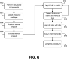
- FIG. 6 shows a flow chart of a not claimed surgical procedure performed using implant 10 and tool 100, in accordance with an example of the present disclosure.
- the steps or operations of the method of FIG. 6 are illustrated in a particular order for convenience and clarity; many of the discussed operations can be performed in a different sequence or in parallel, and some operations may be excluded, without materially impacting other operations.
- the method of FIG. 6 includes operations performed by multiple different actors, devices, and/or sy stems. It is understood that subsets of the operations discussed in the method of FIG. 6 attributable to a single actor, device, or system could be considered a separate standalone process or method.
- a sternum such as sternum 104 can be removed or resected in a procedure at step 602.
- Ribs 102 can also be resected or detached from sternum 104 at step 604.
- manubrium 104 can be partially or fully removed from rib cage 100 at step 602.
- cartilage 108 can be detached from sternum 104 at step 604.
- step 606 can be performed, where sternal implant 12 is positioned to replace sternum 104.
- sternal implant 12 can be secured at superior portion 18 to sternum 104 and/or manubrium 106 using bone fasteners.
- cartilage links 22 can be sutured to cartilage 108 and rib links 14 can be secured to ribs 102.
- cartilage links 22 can be sutured to cartilage 108 after rib links 14 are secured to sternal implant 12 and ribs 102.
- Rib links 14 can alternatively be secured to ribs 102 in later step s, as described below.
- tool 100 can be used to lag one of rib links 14 to matrix 19, so that fasteners 16 can be used to secure the rib link 14 to matrix 19. Tool 100 can then be removed so that fastening or securing can be completed for that rib link at step 612. The process of steps 610 and 612 can be repeated until all of rib links 14 are secured or coupled to sternal implant 12.
- Step 614 can then be performed, where rib links 14 are aligned with ribs 102.
- rib links will need to be bent at strut 30 to align rib links 14.
- alignment tabs 38 can be used to align rib links 14 with ribs 102.
- steps 614 and 616 can be performed priorto steps 610 and 612, as desired by a phy sician.
- distal portions 32 of rib links 14 can be secured to ribs 102 using bone fasteners that engage an anterior face of distal portions 32.
- the procedure can be completed, which can include connecting other soft tissues, such as muscles, ligaments, cartilage, tendons, and bones, and can include closing the opening.
Landscapes
- Health & Medical Sciences (AREA)
- Orthopedic Medicine & Surgery (AREA)
- Surgery (AREA)
- Life Sciences & Earth Sciences (AREA)
- Heart & Thoracic Surgery (AREA)
- Nuclear Medicine, Radiotherapy & Molecular Imaging (AREA)
- Engineering & Computer Science (AREA)
- Biomedical Technology (AREA)
- Neurology (AREA)
- Medical Informatics (AREA)
- Molecular Biology (AREA)
- Animal Behavior & Ethology (AREA)
- General Health & Medical Sciences (AREA)
- Public Health (AREA)
- Veterinary Medicine (AREA)
- Prostheses (AREA)
- Surgical Instruments (AREA)
Claims (13)
- Implantatanordnung (10) für ein menschliches Brustbein und Rippen, wobei die Implantatanordnung (10) Folgendes umfasst:ein Sternumimplantat (12), das an ein Brustbein koppelbar ist und einen Matrixabschnitt (19) umfasst, der eine Vielzahl von Matrixbohrungen (40) beinhaltet; undeine erste Rippenverbindung (14a,..14f), umfassend:einen distalen Abschnitt (32), der dazu konfiguriert ist, an eine Rippe gekoppelt zu werden;einen proximalen Abschnitt (28), der an das Sternumimplantat (12) koppelbar ist, wobei der proximale Abschnitt (28) eine Vielzahl von proximalen Bohrungen (34) umfasst;
undeine Strebe (30), die den distalen Abschnitt (32) mit dem proximalen Abschnitt (28) verbindet, undein Befestigungsmittel (16), um den proximalen Abschnitt (28) an das Sternumimplantat (12) zu koppeln,wobei der Matrixabschnitt (19) dazu konfiguriert ist, den proximalen Abschnitt (28) der Rippenverbindung (14a,..14f) an verschiedenen Stellen nach Wunsch durch Koppeln der Rippenverbindung (14a,..14f) lösbar an die Matrix (19) zu koppeln,wodurch die Matrixbohrungen (40) des Sternumimplantats (12)und die proximalen Bohrungen (34) des proximalen Abschnitts (28) der Rippenverbindung (14a,..14f) ausgerichtet werden. - Implantatanordnung nach Anspruch 1, ferner umfassend:
eine Vielzahl von Rippenverbindungen, welche die erste Rippenverbindung beinhaltet, wobei jede der Vielzahl von Rippenverbindungen lösbar an das Sternumimplantat koppelbar ist. - Implantatanordnung nach einem der Ansprüche 1-2, wobei das Sternumimplantat ferner Folgendes umfasst:einen oberen Abschnitt, der an dem Brustbein sicherbar ist;einen unteren Abschnitt, der an dem Rippenknorpel sicherbar ist; undwobei der Matrixabschnitt zwischen dem oberen und dem unteren Abschnitt angeordnet ist.
- Implantatanordnung nach einem der Ansprüche 1-3, ferner umfassend:
eine Vielzahl von Rippenverbindungen, welche die erste Rippenverbindung beinhaltet, wobei jede der Vielzahl von Rippenverbindungen lösbar an den Matrixabschnitt koppelbar ist. - Implantatanordnung nach einem der Ansprüche 3-4, wobei der Matrixabschnitt dazu konfiguriert ist, einen proximalen Abschnitt von jeder der Vielzahl von Rippenverbindungen aufzunehmen.
- Implantatanordnung nach einem der Ansprüche 1-5, wobei der distale Abschnitt des Sternumimplantats ferner Folgendes umfasst:
eine erste Knorpelverbindung, die sich von dem unteren Abschnitt erstreckt, wobei die Knorpelverbindung eine Vielzahl von Nahtbohrungen beinhaltet. - Implantatanordnung nach einem der Ansprüche 1-6, wobei der untere Abschnitt des Sternumimplantats ferner Folgendes umfasst:
eine Vielzahl von Knorpelverbindungen, welche die erste Knorpelverbindung beinhaltet, wobei sich jede der Vielzahl von Knorpelverbindungen von dem unteren Abschnitt erstreckt und eine Vielzahl von Nahtbohrungen beinhaltet. - Implantatanordnung nach einem der Ansprüche 1-7, wobei die Strebe eine zylindrische Geometrie umfasst.
- Implantatanordnung nach einem der Ansprüche 1-8, wobei der distale Abschnitt Folgendes umfasst:
eine Ausrichtungslasche, die sich von dem distalen Abschnitt erstreckt und dazu konfiguriert ist, mindestens teilweise in die Rippe einzugreifen, um den distalen Abschnitt mit der Rippe auszurichten. - Implantatanordnung nach einem der Ansprüche 1-9, wobei der distale Abschnitt Folgendes umfasst:
eine hintere Oberfläche, die mit der Rippe zusammenpassbar ist und eine an den Patienten angepasste Topographie umfasst. - Implantatanordnung nach einem der Ansprüche 1-10, wobei der distale Abschnitt Folgendes umfasst:
eine Vielzahl von Bohrungen, die zum Aufnehmen von Knochenbefestigungsmitteln konfiguriert ist, wobei die Vielzahl von Bohrungen über den distalen Abschnitt versetzt angeordnet ist, um die zwischen der Rippe und dem distalen Abschnitt übertragene Spannung zu verteilen. - Implantatanordnung nach einem der Ansprüche 1-11, wobei die Strebe dazu konfiguriert ist, sich zu biegen, sodass der distale Abschnitt mit der Rippe ausgerichtet werden kann.
- Implantatanordnung nach Anspruch 12, wobei das Befestigungsmittel eine Antirotationskappe umfasst, die dazu konfiguriert ist, zu verhindern, dass das Befestigungsmittel aus dem proximalen Abschnitt herausrutscht.
Applications Claiming Priority (2)
| Application Number | Priority Date | Filing Date | Title |
|---|---|---|---|
| US15/403,972 US10543027B2 (en) | 2017-01-11 | 2017-01-11 | Adjustable rib and sternal implant |
| PCT/US2017/062234 WO2018132179A1 (en) | 2017-01-11 | 2017-11-17 | Adjustable rib and sternal implant |
Publications (2)
| Publication Number | Publication Date |
|---|---|
| EP3568096A1 EP3568096A1 (de) | 2019-11-20 |
| EP3568096B1 true EP3568096B1 (de) | 2023-05-31 |
Family
ID=60703001
Family Applications (1)
| Application Number | Title | Priority Date | Filing Date |
|---|---|---|---|
| EP17817371.2A Active EP3568096B1 (de) | 2017-01-11 | 2017-11-17 | Verstellbare rippe und sternumimplantat |
Country Status (7)
| Country | Link |
|---|---|
| US (2) | US10543027B2 (de) |
| EP (1) | EP3568096B1 (de) |
| JP (1) | JP6813688B2 (de) |
| CN (1) | CN110191687B (de) |
| AU (1) | AU2017393185B2 (de) |
| CA (1) | CA3049634C (de) |
| WO (1) | WO2018132179A1 (de) |
Families Citing this family (14)
| Publication number | Priority date | Publication date | Assignee | Title |
|---|---|---|---|---|
| ES2748777T3 (es) * | 2015-02-24 | 2020-03-17 | Neuro France Implants | Dispositivo de esternón protésico con manubrio |
| US10543027B2 (en) | 2017-01-11 | 2020-01-28 | Zimmer Biomet CMF and Thoracic, LLC | Adjustable rib and sternal implant |
| CO2017008458A1 (es) * | 2017-08-21 | 2017-08-31 | Conalmedicas S A S | Dispositivo prótesis para reconstrucción de esternón, costillas y clavículas |
| CN113226205B (zh) * | 2018-12-21 | 2024-08-23 | 捷迈拜欧米特Cmf和胸腔有限公司 | 柔性的软骨替换件 |
| KR20200117578A (ko) * | 2019-04-05 | 2020-10-14 | (주)케어테크 | 흉벽 재건 조립체 |
| CO2020003879A1 (es) * | 2020-03-30 | 2021-04-08 | Techfit Digital Surgery Inc | Implante de reemplazo de esternón fabricado en una sola pieza |
| IT202000013486A1 (it) * | 2020-06-08 | 2021-12-08 | Marco Ceccarelli | Dispositivo di protesi di sterno |
| RU2760620C2 (ru) * | 2021-04-26 | 2021-11-29 | Федеральное государственное бюджетное учреждение "Национальный медицинский исследовательский центр радиологии" Министерства здравоохранения Российской Федерации (ФГБУ "НМИЦ радиологии" Минздрава России) | Способ замещения дефекта грудной стенки индивидуальным 3d-имплантом |
| US12042193B2 (en) * | 2021-05-27 | 2024-07-23 | DePuy Synthes Products, Inc. | Sternal plate with rapid re-entry |
| EP4710896A1 (de) | 2023-05-08 | 2026-03-18 | Instituto Tecnológico De Canarias, S.A. | Implantat für das sternoklavikulargelenk |
| WO2025258836A1 (ko) * | 2024-06-10 | 2025-12-18 | 주식회사 큐브랩스 | 인공 흉곽 임플란트 |
| KR102719597B1 (ko) * | 2024-06-10 | 2024-10-21 | 주식회사 큐브랩스 | 인공 흉곽 임플란트 |
| KR102719625B1 (ko) * | 2024-06-10 | 2024-10-21 | 주식회사 큐브랩스 | 인공 흉곽 임플란트 |
| US20260026853A1 (en) * | 2024-07-23 | 2026-01-29 | Jeko Metodiev Madjarov | Device for chest wall reconstruction |
Family Cites Families (17)
| Publication number | Priority date | Publication date | Assignee | Title |
|---|---|---|---|---|
| US5015248A (en) * | 1990-06-11 | 1991-05-14 | New York Society For The Relief Of The Ruptured & Crippled, Maintaining The Hospital For Special Surgery | Bone fracture fixation device |
| EP0583520A1 (de) | 1992-08-18 | 1994-02-23 | Nauchno-Proizvodstennoe Obiedinenie " Ekran" | Gerät zur Behandlung eines trichterförmigen Brustkorbs |
| US6652530B2 (en) * | 2001-09-19 | 2003-11-25 | The University Of Hong Kong | Fixation device |
| US20090248091A1 (en) | 2008-03-19 | 2009-10-01 | Mike Teague | Sternal clamp with rib extension |
| RU2510250C2 (ru) * | 2008-08-19 | 2014-03-27 | Корпорасио Санитария Парк Таули | Устройство для применения при хирургическом лечении воронкообразной деформации грудной клетки и способ лечения |
| US8500782B2 (en) * | 2010-07-22 | 2013-08-06 | Aesculap Implant Systems, Llc | Semi-dynamic fixation plate system |
| FR2975582B1 (fr) * | 2011-05-23 | 2013-06-07 | Ass Marie Lannelongue | Implant d'osteosynthese |
| CN202386768U (zh) * | 2011-11-15 | 2012-08-22 | 常州亨杰医疗器械有限公司 | 肋骨板 |
| US9265543B2 (en) | 2011-12-27 | 2016-02-23 | Pioneer Surgical Technology, Inc. | Bone plate system and method |
| US9597132B2 (en) | 2013-01-12 | 2017-03-21 | Louis Houff | Sternum fixation device and method |
| FR3004337B1 (fr) | 2013-04-15 | 2015-05-01 | Neuro France Implants Nfi | Dispositif de sternum prothetique |
| WO2016034778A1 (fr) * | 2014-09-05 | 2016-03-10 | Neuro France Implants (Nfi) | Dispositif de sternum prothetique |
| ES2748777T3 (es) * | 2015-02-24 | 2020-03-17 | Neuro France Implants | Dispositivo de esternón protésico con manubrio |
| FR3037803B1 (fr) * | 2015-06-23 | 2017-07-07 | I Ceram | Implant de substitution du sternum |
| CN106264794B (zh) * | 2016-07-31 | 2023-10-03 | 上海市肺科医院 | 胸骨重建用组合式假体 |
| CN106109057B (zh) | 2016-08-05 | 2018-04-24 | 常州华森医疗器械有限公司 | 金属胸骨骨架装置 |
| US10543027B2 (en) | 2017-01-11 | 2020-01-28 | Zimmer Biomet CMF and Thoracic, LLC | Adjustable rib and sternal implant |
-
2017
- 2017-01-11 US US15/403,972 patent/US10543027B2/en active Active
- 2017-11-17 CA CA3049634A patent/CA3049634C/en active Active
- 2017-11-17 CN CN201780083083.7A patent/CN110191687B/zh active Active
- 2017-11-17 WO PCT/US2017/062234 patent/WO2018132179A1/en not_active Ceased
- 2017-11-17 JP JP2019537774A patent/JP6813688B2/ja active Active
- 2017-11-17 AU AU2017393185A patent/AU2017393185B2/en active Active
- 2017-11-17 EP EP17817371.2A patent/EP3568096B1/de active Active
-
2019
- 2019-11-20 US US16/689,587 patent/US11357556B2/en active Active
Also Published As
| Publication number | Publication date |
|---|---|
| CA3049634C (en) | 2021-11-09 |
| JP6813688B2 (ja) | 2021-01-13 |
| CA3049634A1 (en) | 2018-07-19 |
| US11357556B2 (en) | 2022-06-14 |
| CN110191687B (zh) | 2022-03-29 |
| US20200085476A1 (en) | 2020-03-19 |
| US20180193073A1 (en) | 2018-07-12 |
| EP3568096A1 (de) | 2019-11-20 |
| CN110191687A (zh) | 2019-08-30 |
| AU2017393185A1 (en) | 2019-07-11 |
| WO2018132179A1 (en) | 2018-07-19 |
| JP2020503967A (ja) | 2020-02-06 |
| US10543027B2 (en) | 2020-01-28 |
| AU2017393185B2 (en) | 2020-04-09 |
Similar Documents
| Publication | Publication Date | Title |
|---|---|---|
| US11357556B2 (en) | Adjustable rib and sternal implant | |
| US10828067B2 (en) | Compressive distal humerus plating system | |
| US9468482B2 (en) | Securing fasteners | |
| AU2010101470B4 (en) | Tool jig for bone implant assembly | |
| CN103179922B (zh) | 用于股骨髋臼撞击手术的植入物、外科手术方法和器械 | |
| US12239348B2 (en) | Fracture and nonunion rib implants | |
| AU2017311669B2 (en) | Bone fixation system | |
| JP2008536533A (ja) | 整形外科用プレートシステム及びその使用法 | |
| CN103442665A (zh) | 植入体 | |
| WO2018136593A1 (en) | Tibial tray with removable spikes | |
| US20140358242A1 (en) | Implant augment | |
| US20230285060A1 (en) | Fracture and nonunion rib implants | |
| US11896274B2 (en) | Hinge plate assembly | |
| CN209018912U (zh) | 一种用于防止肩锁关节脱位钢板 |
Legal Events
| Date | Code | Title | Description |
|---|---|---|---|
| STAA | Information on the status of an ep patent application or granted ep patent |
Free format text: STATUS: UNKNOWN |
|
| STAA | Information on the status of an ep patent application or granted ep patent |
Free format text: STATUS: THE INTERNATIONAL PUBLICATION HAS BEEN MADE |
|
| PUAI | Public reference made under article 153(3) epc to a published international application that has entered the european phase |
Free format text: ORIGINAL CODE: 0009012 |
|
| STAA | Information on the status of an ep patent application or granted ep patent |
Free format text: STATUS: REQUEST FOR EXAMINATION WAS MADE |
|
| 17P | Request for examination filed |
Effective date: 20190725 |
|
| AK | Designated contracting states |
Kind code of ref document: A1 Designated state(s): AL AT BE BG CH CY CZ DE DK EE ES FI FR GB GR HR HU IE IS IT LI LT LU LV MC MK MT NL NO PL PT RO RS SE SI SK SM TR |
|
| AX | Request for extension of the european patent |
Extension state: BA ME |
|
| DAV | Request for validation of the european patent (deleted) | ||
| DAX | Request for extension of the european patent (deleted) | ||
| GRAP | Despatch of communication of intention to grant a patent |
Free format text: ORIGINAL CODE: EPIDOSNIGR1 |
|
| STAA | Information on the status of an ep patent application or granted ep patent |
Free format text: STATUS: GRANT OF PATENT IS INTENDED |
|
| INTG | Intention to grant announced |
Effective date: 20221208 |
|
| GRAS | Grant fee paid |
Free format text: ORIGINAL CODE: EPIDOSNIGR3 |
|
| GRAA | (expected) grant |
Free format text: ORIGINAL CODE: 0009210 |
|
| STAA | Information on the status of an ep patent application or granted ep patent |
Free format text: STATUS: THE PATENT HAS BEEN GRANTED |
|
| AK | Designated contracting states |
Kind code of ref document: B1 Designated state(s): AL AT BE BG CH CY CZ DE DK EE ES FI FR GB GR HR HU IE IS IT LI LT LU LV MC MK MT NL NO PL PT RO RS SE SI SK SM TR |
|
| REG | Reference to a national code |
Ref country code: GB Ref legal event code: FG4D Ref country code: CH Ref legal event code: EP |
|
| REG | Reference to a national code |
Ref country code: AT Ref legal event code: REF Ref document number: 1570510 Country of ref document: AT Kind code of ref document: T Effective date: 20230615 Ref country code: DE Ref legal event code: R096 Ref document number: 602017069255 Country of ref document: DE |
|
| REG | Reference to a national code |
Ref country code: IE Ref legal event code: FG4D |
|
| REG | Reference to a national code |
Ref country code: LT Ref legal event code: MG9D |
|
| REG | Reference to a national code |
Ref country code: NL Ref legal event code: MP Effective date: 20230531 |
|
| REG | Reference to a national code |
Ref country code: AT Ref legal event code: MK05 Ref document number: 1570510 Country of ref document: AT Kind code of ref document: T Effective date: 20230531 |
|
| PG25 | Lapsed in a contracting state [announced via postgrant information from national office to epo] |
Ref country code: SE Free format text: LAPSE BECAUSE OF FAILURE TO SUBMIT A TRANSLATION OF THE DESCRIPTION OR TO PAY THE FEE WITHIN THE PRESCRIBED TIME-LIMIT Effective date: 20230531 Ref country code: NO Free format text: LAPSE BECAUSE OF FAILURE TO SUBMIT A TRANSLATION OF THE DESCRIPTION OR TO PAY THE FEE WITHIN THE PRESCRIBED TIME-LIMIT Effective date: 20230831 Ref country code: ES Free format text: LAPSE BECAUSE OF FAILURE TO SUBMIT A TRANSLATION OF THE DESCRIPTION OR TO PAY THE FEE WITHIN THE PRESCRIBED TIME-LIMIT Effective date: 20230531 Ref country code: AT Free format text: LAPSE BECAUSE OF FAILURE TO SUBMIT A TRANSLATION OF THE DESCRIPTION OR TO PAY THE FEE WITHIN THE PRESCRIBED TIME-LIMIT Effective date: 20230531 |
|
| PG25 | Lapsed in a contracting state [announced via postgrant information from national office to epo] |
Ref country code: RS Free format text: LAPSE BECAUSE OF FAILURE TO SUBMIT A TRANSLATION OF THE DESCRIPTION OR TO PAY THE FEE WITHIN THE PRESCRIBED TIME-LIMIT Effective date: 20230531 Ref country code: PL Free format text: LAPSE BECAUSE OF FAILURE TO SUBMIT A TRANSLATION OF THE DESCRIPTION OR TO PAY THE FEE WITHIN THE PRESCRIBED TIME-LIMIT Effective date: 20230531 Ref country code: NL Free format text: LAPSE BECAUSE OF FAILURE TO SUBMIT A TRANSLATION OF THE DESCRIPTION OR TO PAY THE FEE WITHIN THE PRESCRIBED TIME-LIMIT Effective date: 20230531 Ref country code: LV Free format text: LAPSE BECAUSE OF FAILURE TO SUBMIT A TRANSLATION OF THE DESCRIPTION OR TO PAY THE FEE WITHIN THE PRESCRIBED TIME-LIMIT Effective date: 20230531 Ref country code: LT Free format text: LAPSE BECAUSE OF FAILURE TO SUBMIT A TRANSLATION OF THE DESCRIPTION OR TO PAY THE FEE WITHIN THE PRESCRIBED TIME-LIMIT Effective date: 20230531 Ref country code: IS Free format text: LAPSE BECAUSE OF FAILURE TO SUBMIT A TRANSLATION OF THE DESCRIPTION OR TO PAY THE FEE WITHIN THE PRESCRIBED TIME-LIMIT Effective date: 20230930 Ref country code: HR Free format text: LAPSE BECAUSE OF FAILURE TO SUBMIT A TRANSLATION OF THE DESCRIPTION OR TO PAY THE FEE WITHIN THE PRESCRIBED TIME-LIMIT Effective date: 20230531 Ref country code: GR Free format text: LAPSE BECAUSE OF FAILURE TO SUBMIT A TRANSLATION OF THE DESCRIPTION OR TO PAY THE FEE WITHIN THE PRESCRIBED TIME-LIMIT Effective date: 20230901 |
|
| PG25 | Lapsed in a contracting state [announced via postgrant information from national office to epo] |
Ref country code: FI Free format text: LAPSE BECAUSE OF FAILURE TO SUBMIT A TRANSLATION OF THE DESCRIPTION OR TO PAY THE FEE WITHIN THE PRESCRIBED TIME-LIMIT Effective date: 20230531 |
|
| PG25 | Lapsed in a contracting state [announced via postgrant information from national office to epo] |
Ref country code: SK Free format text: LAPSE BECAUSE OF FAILURE TO SUBMIT A TRANSLATION OF THE DESCRIPTION OR TO PAY THE FEE WITHIN THE PRESCRIBED TIME-LIMIT Effective date: 20230531 |
|
| PG25 | Lapsed in a contracting state [announced via postgrant information from national office to epo] |
Ref country code: SM Free format text: LAPSE BECAUSE OF FAILURE TO SUBMIT A TRANSLATION OF THE DESCRIPTION OR TO PAY THE FEE WITHIN THE PRESCRIBED TIME-LIMIT Effective date: 20230531 Ref country code: SK Free format text: LAPSE BECAUSE OF FAILURE TO SUBMIT A TRANSLATION OF THE DESCRIPTION OR TO PAY THE FEE WITHIN THE PRESCRIBED TIME-LIMIT Effective date: 20230531 Ref country code: RO Free format text: LAPSE BECAUSE OF FAILURE TO SUBMIT A TRANSLATION OF THE DESCRIPTION OR TO PAY THE FEE WITHIN THE PRESCRIBED TIME-LIMIT Effective date: 20230531 Ref country code: PT Free format text: LAPSE BECAUSE OF FAILURE TO SUBMIT A TRANSLATION OF THE DESCRIPTION OR TO PAY THE FEE WITHIN THE PRESCRIBED TIME-LIMIT Effective date: 20231002 Ref country code: EE Free format text: LAPSE BECAUSE OF FAILURE TO SUBMIT A TRANSLATION OF THE DESCRIPTION OR TO PAY THE FEE WITHIN THE PRESCRIBED TIME-LIMIT Effective date: 20230531 Ref country code: DK Free format text: LAPSE BECAUSE OF FAILURE TO SUBMIT A TRANSLATION OF THE DESCRIPTION OR TO PAY THE FEE WITHIN THE PRESCRIBED TIME-LIMIT Effective date: 20230531 Ref country code: CZ Free format text: LAPSE BECAUSE OF FAILURE TO SUBMIT A TRANSLATION OF THE DESCRIPTION OR TO PAY THE FEE WITHIN THE PRESCRIBED TIME-LIMIT Effective date: 20230531 |
|
| REG | Reference to a national code |
Ref country code: DE Ref legal event code: R097 Ref document number: 602017069255 Country of ref document: DE |
|
| PLBE | No opposition filed within time limit |
Free format text: ORIGINAL CODE: 0009261 |
|
| STAA | Information on the status of an ep patent application or granted ep patent |
Free format text: STATUS: NO OPPOSITION FILED WITHIN TIME LIMIT |
|
| P01 | Opt-out of the competence of the unified patent court (upc) registered |
Effective date: 20240326 |
|
| PG25 | Lapsed in a contracting state [announced via postgrant information from national office to epo] |
Ref country code: SI Free format text: LAPSE BECAUSE OF FAILURE TO SUBMIT A TRANSLATION OF THE DESCRIPTION OR TO PAY THE FEE WITHIN THE PRESCRIBED TIME-LIMIT Effective date: 20230531 |
|
| 26N | No opposition filed |
Effective date: 20240301 |
|
| PG25 | Lapsed in a contracting state [announced via postgrant information from national office to epo] |
Ref country code: SI Free format text: LAPSE BECAUSE OF FAILURE TO SUBMIT A TRANSLATION OF THE DESCRIPTION OR TO PAY THE FEE WITHIN THE PRESCRIBED TIME-LIMIT Effective date: 20230531 Ref country code: IT Free format text: LAPSE BECAUSE OF FAILURE TO SUBMIT A TRANSLATION OF THE DESCRIPTION OR TO PAY THE FEE WITHIN THE PRESCRIBED TIME-LIMIT Effective date: 20230531 |
|
| PG25 | Lapsed in a contracting state [announced via postgrant information from national office to epo] |
Ref country code: MC Free format text: LAPSE BECAUSE OF FAILURE TO SUBMIT A TRANSLATION OF THE DESCRIPTION OR TO PAY THE FEE WITHIN THE PRESCRIBED TIME-LIMIT Effective date: 20230531 |
|
| PG25 | Lapsed in a contracting state [announced via postgrant information from national office to epo] |
Ref country code: LU Free format text: LAPSE BECAUSE OF NON-PAYMENT OF DUE FEES Effective date: 20231117 |
|
| PG25 | Lapsed in a contracting state [announced via postgrant information from national office to epo] |
Ref country code: MC Free format text: LAPSE BECAUSE OF FAILURE TO SUBMIT A TRANSLATION OF THE DESCRIPTION OR TO PAY THE FEE WITHIN THE PRESCRIBED TIME-LIMIT Effective date: 20230531 Ref country code: LU Free format text: LAPSE BECAUSE OF NON-PAYMENT OF DUE FEES Effective date: 20231117 |
|
| REG | Reference to a national code |
Ref country code: BE Ref legal event code: MM Effective date: 20231130 |
|
| REG | Reference to a national code |
Ref country code: IE Ref legal event code: MM4A |
|
| PG25 | Lapsed in a contracting state [announced via postgrant information from national office to epo] |
Ref country code: IE Free format text: LAPSE BECAUSE OF NON-PAYMENT OF DUE FEES Effective date: 20231117 |
|
| PG25 | Lapsed in a contracting state [announced via postgrant information from national office to epo] |
Ref country code: BE Free format text: LAPSE BECAUSE OF NON-PAYMENT OF DUE FEES Effective date: 20231130 |
|
| PG25 | Lapsed in a contracting state [announced via postgrant information from national office to epo] |
Ref country code: IE Free format text: LAPSE BECAUSE OF NON-PAYMENT OF DUE FEES Effective date: 20231117 Ref country code: BE Free format text: LAPSE BECAUSE OF NON-PAYMENT OF DUE FEES Effective date: 20231130 |
|
| PG25 | Lapsed in a contracting state [announced via postgrant information from national office to epo] |
Ref country code: BG Free format text: LAPSE BECAUSE OF FAILURE TO SUBMIT A TRANSLATION OF THE DESCRIPTION OR TO PAY THE FEE WITHIN THE PRESCRIBED TIME-LIMIT Effective date: 20230531 |
|
| PG25 | Lapsed in a contracting state [announced via postgrant information from national office to epo] |
Ref country code: BG Free format text: LAPSE BECAUSE OF FAILURE TO SUBMIT A TRANSLATION OF THE DESCRIPTION OR TO PAY THE FEE WITHIN THE PRESCRIBED TIME-LIMIT Effective date: 20230531 |
|
| PG25 | Lapsed in a contracting state [announced via postgrant information from national office to epo] |
Ref country code: CY Free format text: LAPSE BECAUSE OF FAILURE TO SUBMIT A TRANSLATION OF THE DESCRIPTION OR TO PAY THE FEE WITHIN THE PRESCRIBED TIME-LIMIT; INVALID AB INITIO Effective date: 20171117 |
|
| PG25 | Lapsed in a contracting state [announced via postgrant information from national office to epo] |
Ref country code: HU Free format text: LAPSE BECAUSE OF FAILURE TO SUBMIT A TRANSLATION OF THE DESCRIPTION OR TO PAY THE FEE WITHIN THE PRESCRIBED TIME-LIMIT; INVALID AB INITIO Effective date: 20171117 |
|
| REG | Reference to a national code |
Ref country code: CH Ref legal event code: U11 Free format text: ST27 STATUS EVENT CODE: U-0-0-U10-U11 (AS PROVIDED BY THE NATIONAL OFFICE) Effective date: 20251201 |
|
| PG25 | Lapsed in a contracting state [announced via postgrant information from national office to epo] |
Ref country code: TR Free format text: LAPSE BECAUSE OF FAILURE TO SUBMIT A TRANSLATION OF THE DESCRIPTION OR TO PAY THE FEE WITHIN THE PRESCRIBED TIME-LIMIT Effective date: 20230531 |
|
| PGFP | Annual fee paid to national office [announced via postgrant information from national office to epo] |
Ref country code: DE Payment date: 20251021 Year of fee payment: 9 |
|
| PGFP | Annual fee paid to national office [announced via postgrant information from national office to epo] |
Ref country code: GB Payment date: 20251114 Year of fee payment: 9 |
|
| PGFP | Annual fee paid to national office [announced via postgrant information from national office to epo] |
Ref country code: FR Payment date: 20251112 Year of fee payment: 9 |
|
| PGFP | Annual fee paid to national office [announced via postgrant information from national office to epo] |
Ref country code: CH Payment date: 20251201 Year of fee payment: 9 |