EP3567757B1 - Verfahren und vorrichtung zur auswahl eines empfangspunktes und sendepunktes in einem drahtloskommunikationssystem - Google Patents
Verfahren und vorrichtung zur auswahl eines empfangspunktes und sendepunktes in einem drahtloskommunikationssystem Download PDFInfo
- Publication number
- EP3567757B1 EP3567757B1 EP17896312.0A EP17896312A EP3567757B1 EP 3567757 B1 EP3567757 B1 EP 3567757B1 EP 17896312 A EP17896312 A EP 17896312A EP 3567757 B1 EP3567757 B1 EP 3567757B1
- Authority
- EP
- European Patent Office
- Prior art keywords
- information
- point
- transmission
- transmission point
- reception
- Prior art date
- Legal status (The legal status is an assumption and is not a legal conclusion. Google has not performed a legal analysis and makes no representation as to the accuracy of the status listed.)
- Not-in-force
Links
Images










Classifications
-
- H—ELECTRICITY
- H04—ELECTRIC COMMUNICATION TECHNIQUE
- H04W—WIRELESS COMMUNICATION NETWORKS
- H04W48/00—Access restriction; Network selection; Access point selection
- H04W48/20—Selecting an access point
-
- H—ELECTRICITY
- H04—ELECTRIC COMMUNICATION TECHNIQUE
- H04B—TRANSMISSION
- H04B17/00—Monitoring; Testing
- H04B17/20—Monitoring; Testing of receivers
- H04B17/27—Monitoring; Testing of receivers for locating or positioning the transmitter
-
- H—ELECTRICITY
- H04—ELECTRIC COMMUNICATION TECHNIQUE
- H04W—WIRELESS COMMUNICATION NETWORKS
- H04W16/00—Network planning, e.g. coverage or traffic planning tools; Network deployment, e.g. resource partitioning or cells structures
- H04W16/18—Network planning tools
-
- H—ELECTRICITY
- H04—ELECTRIC COMMUNICATION TECHNIQUE
- H04B—TRANSMISSION
- H04B17/00—Monitoring; Testing
- H04B17/20—Monitoring; Testing of receivers
- H04B17/23—Indication means, e.g. displays, alarms, audible means
-
- H—ELECTRICITY
- H04—ELECTRIC COMMUNICATION TECHNIQUE
- H04B—TRANSMISSION
- H04B17/00—Monitoring; Testing
- H04B17/30—Monitoring; Testing of propagation channels
-
- H—ELECTRICITY
- H04—ELECTRIC COMMUNICATION TECHNIQUE
- H04B—TRANSMISSION
- H04B17/00—Monitoring; Testing
- H04B17/30—Monitoring; Testing of propagation channels
- H04B17/391—Modelling the propagation channel
- H04B17/3913—Predictive models, e.g. based on neural network models
-
- H—ELECTRICITY
- H04—ELECTRIC COMMUNICATION TECHNIQUE
- H04W—WIRELESS COMMUNICATION NETWORKS
- H04W72/00—Local resource management
- H04W72/50—Allocation or scheduling criteria for wireless resources
- H04W72/54—Allocation or scheduling criteria for wireless resources based on quality criteria
- H04W72/542—Allocation or scheduling criteria for wireless resources based on quality criteria using measured or perceived quality
-
- H—ELECTRICITY
- H04—ELECTRIC COMMUNICATION TECHNIQUE
- H04W—WIRELESS COMMUNICATION NETWORKS
- H04W72/00—Local resource management
- H04W72/50—Allocation or scheduling criteria for wireless resources
- H04W72/56—Allocation or scheduling criteria for wireless resources based on priority criteria
Definitions
- 5G or pre-5G communication systems are also called “beyond 4G network” or "post LTE system”.
- 5G communication systems consider utilization of the mmWave band (e.g., 60 GHz band).
- mmWave band e.g. 60 GHz band
- various technologies including beamforming, massive multiple-input multiple-output (massive MIMO), full dimensional MIMO (FD-MIMO), array antennas, analog beamforming, and large scale antennas are considered for 5G communication systems.
- ACM advanced coding and modulation
- FQAM hybrid FSK and QAM modulation
- SWSC sliding window superposition coding
- FBMC filter bank multi carrier
- NOMA non-orthogonal multiple access
- SCMA sparse code multiple access
- IoT Internet of Things
- IoE Internet of Everything
- M2M machine-to-machine
- MTC machine type communication
- IoT environments it is possible to provide intelligent Internet technology services, which collect and analyze data created by interconnected things to add new values to human life.
- IoT technology may be applied to various areas such as smart homes, smart buildings, smart cities, smart or connected cars, smart grids, health-care, smart consumer electronics, and advanced medical services.
- the transmitters 110 and 120 may form transmission beams 112 and 122 to transmit signals.
- US 2014/018084 A1 discloses a method for antenna placement of wireless base stations for cellular phones by determining the placement position of a base station antenna by considering the wireless base station antenna in a region not satisfying a required communication performance.
- embodiments of the disclosure are to provide a method and apparatus for efficiently determining the location of a reception point (Rx point) and a transmission point (Tx point) in network design through an analysis of RF transmission and reception environments.
- a method for generating reception (RX)/transmission (TX) position candidates required for the a tracing simulation step in network design the method being executed by an apparatus in a wireless communication system, the method comprises: obtaining two-dimensional image information and three-dimensional map information of a map for the network design; identifying the three-dimensional map information corresponding to the two-dimensional image information; acquiring one or more characteristics of at least one object from the two-dimensional image information, wherein the one or more characteristics of the at least one object are mapped to corresponding objects displayed on the map; extracting at least one reception point (RX point) based on one or more characteristics of at least one object; forming a transmission point group including at least one transmission point based on the at least one reception point and a reception coverage of the at least one reception point; and assigning a priority for at least one transmission point in the transmission point group and selecting a transmission point according to the assigned priority.
- RX reception
- TX transmission
- Extracting at least one reception point may include: identifying shape information of a first object located in the map based on the image information; identifying characteristic information of a second object included in the first object; and selecting the second object as the reception point based on the shape information and the characteristic information.
- the priority may be assigned based on at least one of the distribution of multi-dwelling units (MDU) in the map, the distribution of single-family units (SFU) in the map, the installation cost of the transmission point, the number of transmission points to be installed, the location of previously installed transmission points, or a user input (i.e., explicit prioritization of the user).
- MDU multi-dwelling units
- SFU single-family units
- Forming a transmission point group may include: examining installation information of the at least one reception point; configuring a surrounding region for the at least one reception point based on the installation information; and selecting at least one transmission point from among plural transmission points based on the surrounding region and the transmission coverage of each of the transmission points.
- Forming a transmission point group may further include: comparing a first location of a previously installed transmission point with a second location of the at least one transmission point; and configuring the previously installed transmission point as the at least one transmission point if the second location is replaceable with the first location according to the comparison result.
- Selecting a transmission point may include: generating combinations for the at least one transmission point from the transmission point group according to the priority; calculating a weight for each of the combinations; selecting a first combination having the highest weight among the combinations; and selecting, if the transmission coverage of the first combination covers the reception area corresponding to the at least one reception point, the first combination as the transmission point.
- Selecting a transmission point may include: selecting, if the transmission coverage of the first combination does not cover the reception area corresponding to the at least one reception point, a second combination having the second highest weight among the combinations; and selecting, if the transmission coverage of the second combination covers the reception area corresponding to the at least one reception point, the second combination as the transmission point.
- an apparatus for generating reception (RX)/transmission (TX) position candidates required for a ray tracing simulation step in network design in a wireless communication system comprises: a transceiver configured to transmit and receive information; and a controller configured to obtain two-dimensional image information and three-dimensional map information of a map for the network design, identify the three-dimensional map information corresponding to the two-dimensional image information, acquire one or more characteristics of at least one object from the two-dimensional image information, extract at least one reception point (RX point) based on the one or more characteristics of the at least one object, form a transmission point group including at least one transmission point based on the at least one reception point and a reception coverage of the at least one reception point, assign a priority for at least one transmission point in the transmission point group, and select a transmission point according to the assigned priority, wherein the one or more characteristics of the at least one object are mapped to corresponding objects displayed on the map.
- reception point RX point
- TX point transmission point
- a block of a flowchart may correspond to a module, a segment or a code containing one or more executable instructions implementing one or more logical functions, or to a part thereof.
- functions described by blocks may be executed in an order different from the listed order. For example, two blocks listed in sequence may be executed at the same time or executed in reverse order.
- unit may refer to a software component or hardware component such as an FPGA or ASIC capable of carrying out a function or an operation.
- unit or the like is not limited to hardware or software.
- a unit or the like may be configured so as to reside in an addressable storage medium or to drive one or more processors.
- Units or the like may refer to software components, object-oriented software components, class components, task components, processes, functions, attributes, procedures, subroutines, program code segments, drivers, firmware, microcode, circuits, data, databases, data structures, tables, arrays, or variables.
- a function provided by a component and unit may be a combination of smaller components and units, and it may be combined with others to compose large components and units.
- Components and units may be configured to drive a device or one or more processors in a secure multimedia card.
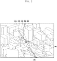
- FIG. 2 it is assumed that one or more transmitters 212, 214 and 216 transmit signals, and the strength of the signals transmitted by the transmitters 212, 214 and 216 is represented in light and shade on the map. The darker shade indicates stronger signal strength, and the lighter shade indicates weaker signal strength.
- the receiver 220 determines the reception strength of the signal in the corresponding region. It is also possible to identify the transmission channel for each possible path from one transmitter 212 to the receiver 220. There may be a signal 242 that is directly received by the receiver 220 from the transmitter 212 and a signal 232 that is reflected by a different object 230 and is received by the receiver 220. By performing a simulation based on ray tracing, it is possible to obtain information about the reception strength of the signals from the transmitters 212, 214 and 216 in a specific region and the propagation paths of the signals.
- the receiver 220 can obtain more accurate signal reception information if at least one of the surface material or the external shape of the signal reflecting object is considered.
- the surface material does not only mean the outer surface of the object but also may include the inner material that may affect the reflection of the radio wave. Such information can be used to more accurately estimate the characteristics of radio wave reflection.
- a radio wave-transmissible obstacle may be located on the path along which the signal is directly transmitted.
- An example of such an obstacle may be a tree.
- An obstacle that can transmit the radio wave but causes signal attenuation like a tree can be considered in the ray tracing simulation. More accurate simulation results can be obtained by considering information about the obstacles capable of transmitting the radio wave.
- the tree is an example of an obstacle that is located on the signal propagation path and causes signal attenuation during radio wave transmission
- the obstacle may be a plant or a structure installed on the propagation path and may also be a different object that may cause signal attenuation.
- the ray tracing simulation can be used to determine the transmission channel for each of the paths through which the RF signal passes, and predict RF signal information at the position of the receiver 220 based on the simulation results.
- the ray tracing simulation may calculate at least one of the signal propagation distance, the environment of a path (e.g., type of the medium), and the effects of reflection and diffraction caused by the 3D terrain or buildings, thereby producing more accurate RF signal information.
- the above channel estimation technique does not have any limitation due to the frequency of the RF signal, can accurately reflect the actual environment, and can be used to determine at least one of the optimal transmission position or the optimal reception position based on the simulation results.
- 5G networks use very high frequency signals of 28 to 60 GHz.
- a ray tracing simulation technique not a mathematical modeling technique, to obtain radio signal information.
- the reflection effect may be calculated by assuming that the surfaces of all buildings have the same RF characteristics.
- this assumption does not guarantee accurate simulation results. Therefore, a ray tracing technique considering this information is required.
- FIGS. 3A and 3B illustrate a scheme for obtaining three-dimensional map information according to an embodiment of the disclosure.
- three-dimensional map information can be obtained based on the actual image information of FIG. 3A and the location information corresponding to the image information. More specifically, the 3D map information of FIG. 3B can be obtained so that the ray tracing simulation can be performed based on the image information.
- the obtained map information of FIG. 3B may include buildings 310, receiver candidate regions 330, and trees 320.
- the transmitter position candidates and the receiver position candidates can be determined based on the obtained map information, and the ray tracing simulation can be performed to determine at least one of the optimum transmitter position or the optimum receiver position.
- objects such as a building 310 may have the characteristics of reflecting or scattering radio waves.
- more precise simulation results can be obtained by considering the surface material and external shape thereof.
- the receiver candidate region 330 may be selectively considered according to ray tracing and may include a portion where a fixed or mobile receiver can be installed. More specifically, a receiver may be installed at a window portion of the building 310, and the receiver installed in the window portion can perform a relay function in communication between the transmitter outside the building and another receiver inside the building. Thus, by performing the ray tracing simulation in consideration of the receiver candidate region 330, it is possible to obtain a result reflecting a better signal reception environment.
- FIGS. 4A and 4B illustrate a scheme for obtaining material information of objects in an image using image information according to an embodiment of the disclosure.
- the computing device may obtain actual environmental information based on at least one of the map information or the image information.
- the actual environmental information may include information about objects and characteristics thereof located on the communication path. More specifically, the two-dimensional image information can be analyzed to identify the characteristics of objects that can be located on the communication path.
- the characteristics of an object may include at least one of the surface material of the object or the external shape of the object. In the case of an object capable of transmitting the radio wave, the characteristics of the object may include information about the shape of the object and the degree of signal attenuation during transmission.
- the computing device may map the actual environmental information of the communication path to the three-dimensional map information based on the information obtained at steps 510 and 520.
- the additional information obtained from the two-dimensional image information may be mapped to the object corresponding to the three-dimensional map information based on the additional information included in the two-dimensional image information.
- the computing device may perform a ray tracing simulation based on the information generated at step 530.
- the ray tracing simulation may be performed while changing the beam information in sequence with respect to the beam in a specific direction, or may be performed by assuming that beams in all directions that can be transmitted by the transmitter are transmitted within the same time period.
- the ray tracing simulation it is possible to predict and analyze the quality of the signal that can be received by the receiver in consideration of the path through which the signal is transmitted from the transmitter to the receiver and the actual environmental information along the path.
- at least one of the transmitter position or the receiver position may be determined based on the three-dimensional map information, and the signal transmission environment can be identified based on the information mapped at step 530.
- adaptive network management can be possible by use of information on signal reception measured in an actual environment. More specifically, when there is a change in the surrounding environment after the transmitter is installed, an additional ray tracing simulation may be performed in consideration of the changed environment. Network management may be performed by adjusting the transmitter position based on the simulation results. In addition to adjusting the transmitter position, the network management may include modifying the information about the beams emitted by the transmitter. For example, the transmitter can determine the transmission beam and the reception beam based on the ray tracing simulation results. Beam alignment may be performed based on the ray tracing simulation results to determine the transmission beam and the reception beam. Such adaptive network management can be performed on a periodic basis.
- the optimum positions and number of base stations can be selected in consideration of the coverage of the base station, local radio environment (propagation distance, frequency band, distribution of obstacles on the propagation path, height of buildings or obstacles, height of the base station antenna, and height of the mobile station), and the call volume (number of subscribers per unit area).
- the area can be divided into cells according to preset criteria (call volume, area size, etc.) and a simulation can be performed based on the coverage of each cell.
- the manual method where the user directly checks the radio environment of the base station, set the location thereof, and perform terrain deign, may be relatively more accurate than the method of automatically selecting the base station.
- this manual method may fail to examine a specific area, and may take a long time and be very inefficient in terms of human resources.
- the information about the radio environment and the call volume of the area must be provided.
- Providing information only on the location of the base station to be newly installed without considering the existing installed base stations may cause inefficiency in terms of installation and cost. Also, accuracy may be impaired if the characteristics of the real environment or user's intent (complex multi-family houses, single-family villas, minimum number, or minimum cost) are not reflected.
- the simulation is calculated on the basis of the cell coverage, and there may be a significant difference between the simulation result and the actual network design result.
- the disclosure relates to a method of generating RX/TX position candidates required for the ray tracing simulation step in network design, and relates to a method for automatically generating RX/TX position candidates according to user's prioritization in consideration of image information recognition through deep learning and information on existing TX installations (or central office information).
- the optimal RX/TX candidate is automatically generated by utilizing the image information and central office information, thereby enhancing the user convenience and reducing the time required for the simulation step in network design.
- the transmission (TX) point may refer to the location of the transmitter in a wireless communication system, e.g., the location where the base station is installed
- the reception (RX) point may refer to the location of the receiver in the wireless communication system, e.g., the location where the terminal is installed.
- FIG. 6 describes a method for selecting a transmission point in a wireless communication system according to an embodiment of the disclosure.
- the apparatus for selecting a transmission point in a wireless communication system may extract at least one reception point (RX point) based on the image information in a map, form a transmission point group including at least one transmission point based on the at least one reception point, assign a priority for at least one transmission point in the transmission point group, and select a transmission point according to the assigned priority.
- the image information may be extracted based on at least one of two-dimensional map information or three-dimensional map information.
- the apparatus may identify signal characteristics transmitted from the selected transmission point to the at least one reception point, and design a network of the wireless communication system based on the identified signal characteristics.
- a storage medium may store a program including instructions configured to implement the method according to embodiments of the disclosure.
- the apparatus for selecting a transmission point in a wireless communication system may set an extraction range in the map.
- the extraction range may be set according to a user input.
- the extraction range may refer to the range of a region in which the user wishes to design a network.
- the apparatus may extract a RX point based on the image information in the map.
- the apparatus may include an automatic reception point extraction module for recognizing specific objects (e.g., buildings, or windows) via deep learning from the image information in the area corresponding to the extraction range and extracting the positions of all reception points suitable for the objects.
- the apparatus may form a transmission point group including at least one transmission point (TX point).
- the transmission point group may indicate a group of transmission point candidates that can be selected as a transmission point.
- the apparatus may include a transmission point group extraction module that extracts all possible transmission points by using the extracted reception point, image information through deep learning, and information on the existing transmission points (e.g., base station).
- the apparatus may assign a priority for at least one transmission point in the transmission point group.
- the device may control the priority (e.g., set control parameters).
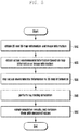
- FIG. 7 depicts a process of extracting the reception point mentioned in FIG. 6 according to an embodiment of the disclosure.
- Extracting at least one reception point based on the image information in the map may include: identifying the shape information of a first object located in the map based on the image information; identifying characteristic information of a second object included in the first object; and selecting the second object as the reception point based on the shape information and the characteristic information.
- the first object and the second object may be specified in advance by a user input or a specific algorithm, and may refer to a region where the reception point can be located in the map.
- the first object may physically include the second object.
- the first object may be a building and the second object may be a window.
- the shape information of the first object may include information about at least one of the height, the size, or the shape of the first object.
- the characteristic information of the second object may include information about at least one of the height, the size, the number, or the position of the second object.
- the automatic reception point extraction module may analyze the image information extracted based on at least one of the two-dimensional map information or the three-dimensional map information corresponding to the map (705).
- the automatic reception point extraction module may analyze the road view of each building through deep learning and identify (or recognize) the height, size, and shape of the buildings in the map extraction range (710). For a specific building, the automatic reception point extraction module can identify (or recognize) the height, size, number, and location in the building of windows included in the building (715).
- the automatic reception point extraction module may set the recognized window or the specified window as a reception point (725).
- the automatic reception point extraction module may check whether there is a nearby building similar to the current building under consideration in terms of height, size, shape or the like in the map (745). If there is a similar building, the automatic reception point extraction module can set the reception points according to the reception points of the similar building (750). If there is no similar building, the automatic reception point extraction module can set reception points on all the surfaces of the current building at preset intervals (755).
- the automatic reception point extraction module can confirm (or store) information about the number and location of reception points for each building (730).
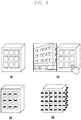
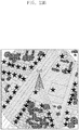
- FIG. 8 shows an example of extracting the reception point as depicted in FIG. 7 according to an embodiment of the disclosure.
- the automatic reception point extraction module can set the reception points along the windows.
- the automatic reception point extraction module may add a window to be used as a reception point according to the manual update function initiated in response to a user input.
- the automatic reception point extraction module can set reception points at regular intervals on all sides of the building.
- FIG. 9 illustrates a process of configuring a transmission point group mentioned in FIG. 6 according to an embodiment of the disclosure.
- the transmission point group extraction module may examine the installation information of at least one reception point.
- the transmission point group extraction module can identify the transmission coverage of the plural transmission points.
- the installation information may indicate the installation location and number of the reception points.
- the transmission point group extraction module may set a surrounding region for the at least one reception point based on the installation information.
- the surrounding region may correspond to the reception coverage of a reception point.
- the transmission point group extraction module may select at least one transmission point among the plural transmission points according to the surrounding region and the TX coverage of each transmission point through image recognition based on deep learning.
- the transmission point group extraction module may identify the location and number of previously installed transmission points.
- the transmission point group extraction module may examine the location and number of the previously installed transmission points at step S960, and may form a transmission point group including all or some of the at least one transmission point at step S970.
- the transmission point group extraction module may compare the first location of a previously installed transmission point with the second location of the at least one transmission point. If the second location can be replaced with the first location according to the comparison result, the transmission point group extraction module may include the previously installed transmission point in the transmission point group.
- FIG. 10 shows an example of the surrounding region mentioned in FIG. 9 according to an embodiment of the disclosure.
- a region within a preset distance (e.g., a radius of 1km) from each reception point may be set as the surrounding region.
- the preset distance may be determined in consideration of the RX coverage of the reception point.
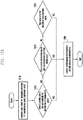
- FIG. 11 illustrates a process of selecting a transmission point based on the priority mentioned in FIG. 6 according to an embodiment of the disclosure.
- Selecting a transmission point from the transmission point group based on the assigned priority may include: generating combinations for at least one transmission point from the transmission point group according to the priority; calculating a weight for each of the combinations; selecting a first combination having the highest weight among the combinations; and, if the TX coverage of the first combination covers the reception area corresponding to the at least one reception point, selecting the first combination as the transmission point.
- selecting a transmission point may include: selecting a second combination having the second highest weight among the combinations; and, if the TX coverage of the second combination covers the reception area corresponding to the at least one reception point, selecting the second combination as the transmission point.
- the apparatus for selecting a transmission point in a wireless communication system may identify a transmission point group at step S1110, and may assign priorities for transmission points in the transmission point group based on a user input at steps S1120 and S1130. In one embodiment, the priority may be determined based on a preset control parameter.
- the priority may be set based on at least one of the distribution of multi-dwelling units (MDU) in the map, the distribution of single-family units (SFU) in the map, the installation cost of the transmission point, the number of transmission points to be installed, the location of previously installed transmission points, or a user input (i.e., explicit prioritization of the user).
- MDU multi-dwelling units
- SFU single-family units
- the apparatus may generate combinations for at least one transmission point from the transmission point group according to the assigned priority at step S1140, and may calculate weights for the combinations at step S1150.
- the apparatus may select a first combination having the highest weight among the combinations at step S1160.
- the apparatus may determine whether the transmission coverage of the current combination (e.g., first combination) covers the reception area corresponding to the reception points at step S1170.
- the apparatus may select a second combination having the second highest weight among the combinations at step S1180.
- FIGS. 12A and 12B show an example of the transmission point selection process described in FIG. 11 according to an embodiment of the disclosure.
- the user assigns the priority for a transmission point in consideration of the minimum cost.
- the apparatus can check whether there is a site where the transmission point can be installed other than the existing site.
- the site where the transmission point can be installed may be a utility pole, a roof top, a light pole, or a tower.
- the apparatus can find a new site for installing the transmission point.
- the new installation site may be a new pole or an intersection.
- the rental cost and installation cost are not incurred. If the transmission point is installed at an available site other than the existing site, no installation cost is incurred but the rental cost may be incurred. If the transmission point is installed at a new site, both the rental cost and installation cost may be incurred.
- FIG. 12B is a table showing an example of assigning the priority for the transmission point site according to a user input (minimum cost, MDU, or SFU) for priority assignment.
- the first priority is assigned to the existing place (existing site, or existing tower)
- the second priority is assigned to a place where a transmission point can be installed other than the existing place (utility pole, roof top, or light pole)
- the third priority is assigned to a new installation site (new pole).
- the user has selected "MDU (multi-dwelling unit)" as a criterion for assigning the priority of the transmission point location, and the priority can be assigned as shown in the table.
- MDU multi-dwelling unit
- the user having selected "MDU” may indicate that the region for installing the transmission point is an area where the MDUs are densely distributed.
- the user has selected "SFU (single-family unit)" as a criterion for assigning the priority of the transmission point location, and the priority can be assigned as shown in the table.
- SFU single-family unit
- the user having selected "SFU” may indicate that the region for installing the transmission point is an area where the SFUs are densely distributed.
- FIGS. 13A and 13B show an example of selecting a transmission point according to an embodiment of the disclosure.
- the transmission point can be selected according to the following optimum combination selection criteria.
- FIG. 13A shows a case of selecting the transmission point when the user selects "MDU”
- FIG. 13B shows a case of selecting the transmission point when the user selects "SFU”.
- the first TX point TX(A) is connected to one RX point, in which the sum of the distances of all TX points ⁇ -> RX points is 34m.
- the second TX point TX(B) is connected to three RX points, in which the sum of the distances of all TX points ⁇ -> RX points is 115m (36+40+39).
- the third TX point TX(C) is connected to two RX points, in which the sum of the distances of all TX points ⁇ -> RX points is 79m.
- the fourth TX point TX(D) is connected to three RX points, in which the sum of the distances of all TX points ⁇ -> RX points is 66m (24+19+23).
- the apparatus 1400 for selecting a transmission point in a wireless communication system may include a transceiver 1405, a storage 1410, and a controller 1415.
- the storage 1410 may store at least one of information related to the apparatus 1400 or information transmitted and received through the transceiver 1405.
- the storage 1410 may also store all information needed for the simulation in the embodiments herein, such as information about the simulation results, information about the shape (size, height, or position) of the objects in the map obtained by image analysis, two-dimensional map information, three-dimensional map information, and information on the shape of objects mapped to the map. Based on at least one of the simulation result or the comparison result, new information may be added to the information stored in the storage 1410, or some of the information stored in the storage 1410 may be deleted or updated.
- the controller 1415 can control the overall operation of the apparatus 1400, and can control the apparatus to perform operations described in the above embodiments.
- the controller 1415 may be configured to extract at least one reception point (RX point) based on the image information in a map, form a transmission point group including at least one transmission point based on the at least one reception point, assign a priority for at least one transmission point in the transmission point group, and select an optimal transmission point according to the assigned priority.
- RX point reception point
- the controller 1415 may include at least one processor.
- the at least one processor may be controlled by a program that includes instructions configured to implement the method described in the embodiments of the disclosure.
- the program may be stored in a storage medium, which may include volatile or nonvolatile memory. This memory may be a medium capable of storing data, and there is no restriction on the type of the medium if the instructions can be stored.
Landscapes
- Engineering & Computer Science (AREA)
- Computer Networks & Wireless Communication (AREA)
- Signal Processing (AREA)
- Physics & Mathematics (AREA)
- Electromagnetism (AREA)
- Quality & Reliability (AREA)
- Computer Security & Cryptography (AREA)
- Artificial Intelligence (AREA)
- Evolutionary Computation (AREA)
- Mobile Radio Communication Systems (AREA)
Claims (15)
- Computerimplementiertes Verfahren zum Erzeugen von Empfangs-/Sende-, RX-/TX-, Positionskandidaten, die für einen Verfolgungssimulationsschritt im Netzentwurf erforderlich sind, wobei das Verfahren durch eine Vorrichtung in einem Drahtloskommunikationssystem ausgeführt wird, wobei das Verfahren Folgendes umfasst:Erhalten (510) von zweidimensionalen Bildinformationen und dreidimensionalen Karteninformationen einer Karte für den Netzentwurf;Identifizieren (510) der dreidimensionalen Karteninformationen, die den zweidimensionalen Bildinformationen entsprechen;Erfassen (520) einer oder mehrerer Merkmale zumindest eines Objekts aus den zweidimensionalen Bildinformationen,wobei das eine bzw. die mehreren Merkmale des zumindest einen Objekts auf entsprechende, auf der Karte angezeigte Objekte abgebildet werden;Extrahieren (620) zumindest eines Empfangspunkts, RX-Punkts, basierend auf einem oder mehreren Merkmalen zumindest eines Objekts;Ausbilden (630) einer Sendepunktgruppe, die zumindest einen Sendepunkt enthält, basierend auf dem zumindest einen Empfangspunkt und einer Empfangsabdeckung des zumindest einen Empfangspunkts; undZuweisen (640) einer Priorität für zumindest einen Sendepunkt in der Sendepunktgruppe und Auswählen (650) eines Sendepunkts gemäß der zugewiesenen Priorität.
- Verfahren nach Anspruch 1, wobei das Extrahieren zumindest eines Empfangspunkts Folgendes umfasst:Identifizieren von Forminformationen eines ersten Objekts, das sich in der Karte befindet, basierend auf den zweidimensionalen Bildinformationen;Identifizieren von Merkmalsinformationen eines im ersten Objekt enthaltenen zweiten Objekts undAuswählen des zweiten Objekts als Empfangspunkt basierend auf den Forminformationen und den Merkmalsinformationen.
- Verfahren nach Anspruch 2, wobei die Forminformationen Informationen über mindestens eines aus der Höhe, der Größe und der Form des ersten Objekts umfassen und wobei die Merkmalsinformationen Informationen über mindestens eines aus der Höhe, der Größe, der Zahl und der Position des zweiten Objekts umfassen.
- Verfahren nach Anspruch 2, wobei das zweite Objekt ein Objekt ist, dessen Durchlässigkeit für Funkwellen unter einem Schwellenwert liegt.
- Verfahren nach Anspruch 1, wobei die Priorität basierend auf mindestens einem aus der Verteilung von Mehrfamilienwohneinheiten, MDU, in der Karte, der Verteilung von Einfamilienwohneinheiten, SFU, in der Karte, den Installationskosten des Sendepunkts, der Anzahl von zu installierenden Sendepunkten, der Position von zuvor installierten Sendepunkten und einer Benutzereingabe zugewiesen wird.
- Verfahren nach Anspruch 1, wobei das Ausbilden einer Sendepunktgruppe Folgendes umfasst:Prüfen (910) von Installationsinformationen des zumindest einen Empfangspunkts;Konfigurieren (930) eines Umgebungsbereichs für den zumindest einen Empfangspunkt basierend auf den Installationsinformationen undAuswählen (940) zumindest eines Sendepunkts aus mehreren Sendepunkten basierend auf dem Umgebungsbereich und der Sendeabdeckung jedes der Sendepunkte.
- Verfahren nach Anspruch 6, wobei das Ausbilden einer Sendepunktgruppe ferner Folgendes umfasst:Vergleichen einer ersten Position eines zuvor installierten Sendepunkts mit einer zweiten Position des zumindest einen Sendepunkts undKonfigurieren des zuvor installierten Sendepunkts als den zumindest einen Sendepunkt, wenn die zweite Position gemäß dem Vergleichsergebnis durch die erste Position ersetzbar ist.
- Verfahren nach Anspruch 1, wobei das Auswählen eines Sendepunkts Folgendes umfasst:Erzeugen (1140) von Kombinationen für den zumindest einen Sendepunkt aus der Sendepunktgruppe gemäß der Priorität;Berechnen (1150) eines Gewichts für jede der Kombinationen;Auswählen (1160) einer ersten Kombination mit dem höchsten Gewicht unter den Kombinationen undAuswählen der ersten Kombination als den Sendepunkt, wenn die Sendeabdeckung der ersten Kombination den Empfangsbereich, der dem zumindest einen Empfangspunkt entspricht, abdeckt.
- Verfahren nach Anspruch 8, wobei das Auswählen eines Sendepunkts Folgendes umfasst:Auswählen (1180) einer zweiten Kombination mit dem zweithöchsten Gewicht unter den Kombinationen, wenn die Sendeabdeckung der ersten Kombination nicht den Empfangsbereich, der dem zumindest einen Empfangspunkt entspricht, abdeckt; undAuswählen der zweiten Kombination als den Sendepunkt, wenn die Sendeabdeckung der zweiten Kombination den Empfangsbereich, der dem zumindest einen Empfangspunkt entspricht, abdeckt.
- Verfahren nach Anspruch 1, ferner umfassend:Identifizieren von Merkmalen eines vom ausgewählten Sendepunkt an den zumindest einen Empfangspunkt gesendeten Signals; undEntwerfen eines Netzes des Drahtloskommunikationssystems basierend auf den identifizierten Signalmerkmalen.
- Verfahren nach Anspruch 1, wobei die zweidimensionalen Bildinformationen basierend auf mindestens einem aus zweidimensionalen Karteninformationen und den dreidimensionalen Karteninformationen der Karte bestimmt werden.
- Speichermedium, das ein Programm speichert, das Anweisungen enthält, die, wenn das Programm von einem Computer ausgeführt wird, den Computer veranlassen, das Verfahren nach einem der Ansprüche 1 bis 11 zu implementieren.
- Vorrichtung zum Erzeugen von Empfang-/Sende-, RX/TX-, Positionskandidaten, die für einen Strahlverfolgungssimulationsschritt im Netzentwurf in einem Drahtloskommunikationssystem erforderlich sind, wobei die Vorrichtung Folgendes umfasst:einen Sender-Empfänger, der konfiguriert ist, um Informationen zu senden und zu empfangen; undeinen Controller, der konfiguriert ist, um zweidimensionale Bildinformationen und dreidimensionale Karteninformationen einer Karte für den Netzentwurf zu erhalten (510), die dreidimensionalen Karteninformationen, die den zweidimensionalen Bildinformationen entsprechen, zu identifizieren (510), ein oder mehrere Merkmale zumindest eines Objekts aus den zweidimensionalen Bildinformationen zu erfassen (520), basierend auf dem einen bzw. den mehreren Merkmalen des zumindest einen Objekts zumindest einen Empfangspunkt, RX-Punkt, zu extrahieren (620), basierend auf erforderlich dem zumindest einen Empfangspunkt und einer Empfangsabdeckung des zumindest einen Empfangspunkts eine Sendepunktgruppe auszubilden (630), die zumindest einen Sendepunkt enthält, eine Priorität für zumindest einen Sendepunkt in der Sendepunktgruppe zuzuweisen (640) und einen Sendepunkt gemäß der zugewiesenen Priorität auszuwählen (650),wobei das eine bzw. die mehreren Merkmale des zumindest einen Objekts auf entsprechende, auf der Karte angezeigte Objekte abgebildet werden.
- Vorrichtung nach Anspruch 13, wobei der Controller konfiguriert ist, um basierend auf den zweidimensionalen Bildinformationen Forminformationen eines ersten Objekts, das sich in der Karte befindet, zu identifizieren, Merkmalsinformationen eines zweiten Objekts, das im ersten Objekt enthalten ist, zu identifizieren und basierend auf den Forminformationen und den Merkmalsinformationen das zweite Objekt als den Empfangspunkt zu identifizieren.
- Vorrichtung nach Anspruch 14, wobei die Forminformationen Informationen über mindestens eines aus der Höhe, der Größe und der Form des ersten Objekts umfassen und wobei die Merkmalsinformationen Informationen über mindestens eines aus der Höhe, der Größe, der Zahl und der Position des zweiten Objekts umfassen.
Applications Claiming Priority (2)
| Application Number | Priority Date | Filing Date | Title |
|---|---|---|---|
| KR1020170018851A KR102655438B1 (ko) | 2017-02-10 | 2017-02-10 | 무선 통신 시스템에서 수신 포인트 및 송신 포인트를 선택하기 위한 방법 및 장치 |
| PCT/KR2017/002663 WO2018147501A1 (ko) | 2017-02-10 | 2017-03-13 | 무선 통신 시스템에서 수신 포인트 및 송신 포인트를 선택하기 위한 방법 및 장치 |
Publications (3)
| Publication Number | Publication Date |
|---|---|
| EP3567757A1 EP3567757A1 (de) | 2019-11-13 |
| EP3567757A4 EP3567757A4 (de) | 2020-01-15 |
| EP3567757B1 true EP3567757B1 (de) | 2021-09-29 |
Family
ID=63106943
Family Applications (1)
| Application Number | Title | Priority Date | Filing Date |
|---|---|---|---|
| EP17896312.0A Not-in-force EP3567757B1 (de) | 2017-02-10 | 2017-03-13 | Verfahren und vorrichtung zur auswahl eines empfangspunktes und sendepunktes in einem drahtloskommunikationssystem |
Country Status (4)
| Country | Link |
|---|---|
| US (1) | US11310734B2 (de) |
| EP (1) | EP3567757B1 (de) |
| KR (1) | KR102655438B1 (de) |
| WO (1) | WO2018147501A1 (de) |
Families Citing this family (4)
| Publication number | Priority date | Publication date | Assignee | Title |
|---|---|---|---|---|
| JP6955144B2 (ja) * | 2017-06-29 | 2021-10-27 | 富士通株式会社 | 無線機器の設置位置決定装置、無線機器の設置位置決定方法及び無線機器の設置位置決定プログラム |
| US11546068B2 (en) * | 2017-08-11 | 2023-01-03 | Cohere Technologies, Inc. | Ray tracing technique for wireless channel measurements |
| US20250184753A1 (en) * | 2022-03-09 | 2025-06-05 | Nippon Telegraph And Telephone Corporation | Interference evaluation method, interference evaluation apparatus and interference evaluation program |
| US20240265619A1 (en) * | 2023-02-07 | 2024-08-08 | Nvidia Corporation | Learning digital twins of radio environments |
Family Cites Families (10)
| Publication number | Priority date | Publication date | Assignee | Title |
|---|---|---|---|---|
| US20040030562A1 (en) * | 2002-08-08 | 2004-02-12 | Williams Douglas M. | Composite energy emission information system for improved safety to site personnel |
| US7973716B2 (en) * | 2005-01-19 | 2011-07-05 | The Charles Stark Draper Laboratory, Inc. | Systems and methods for transparency mapping using multipath signals |
| US7764230B2 (en) * | 2007-03-13 | 2010-07-27 | Alcatel-Lucent Usa Inc. | Methods for locating transmitters using backward ray tracing |
| KR100895299B1 (ko) | 2007-05-30 | 2009-05-07 | 한국전자통신연구원 | 레이 트레이싱 방법을 이용한 전파 전달 모델링 방법 및 장치 |
| KR100885936B1 (ko) | 2007-07-25 | 2009-02-26 | 주식회사 케이티프리텔 | 휴대용 단말기를 이용하여 이동통신 시스템의 망을설계하는 방법 |
| JP5074333B2 (ja) * | 2008-09-22 | 2012-11-14 | Kddi株式会社 | 電波伝搬特性推定装置及びコンピュータプログラム |
| JP5886152B2 (ja) * | 2012-07-09 | 2016-03-16 | 株式会社日立製作所 | 無線基地局の配置決定方法及び装置 |
| US9638792B2 (en) * | 2014-07-09 | 2017-05-02 | Verizon Patent And Licensing Inc. | Method and apparatus for detecting obstacles in propagation path of a wireless communication signal |
| CN104363616B (zh) * | 2014-10-27 | 2018-07-03 | 英国Ranplan无线网络设计公司 | 一种室外到室内传播模型预测室内三维空间场强的方法 |
| US10045352B2 (en) * | 2016-01-13 | 2018-08-07 | Futurewei Technologies, Inc. | Channel estimation in large scale MIMO systems using iterative location based spatial filtering |
-
2017
- 2017-02-10 KR KR1020170018851A patent/KR102655438B1/ko active Active
- 2017-03-13 EP EP17896312.0A patent/EP3567757B1/de not_active Not-in-force
- 2017-03-13 US US16/484,644 patent/US11310734B2/en active Active
- 2017-03-13 WO PCT/KR2017/002663 patent/WO2018147501A1/ko not_active Ceased
Also Published As
| Publication number | Publication date |
|---|---|
| US20190380090A1 (en) | 2019-12-12 |
| US11310734B2 (en) | 2022-04-19 |
| KR102655438B1 (ko) | 2024-04-05 |
| EP3567757A1 (de) | 2019-11-13 |
| KR20180092737A (ko) | 2018-08-20 |
| WO2018147501A1 (ko) | 2018-08-16 |
| EP3567757A4 (de) | 2020-01-15 |
Similar Documents
| Publication | Publication Date | Title |
|---|---|---|
| US11153763B2 (en) | Method and device for analyzing communication channels and designing wireless networks, in consideration of information relating to real environments | |
| EP3672118B1 (de) | Verfahren und vorrichtung zur analyse einer kommunikationsumgebung in einem drahtloskommunikationssystem | |
| EP3567890B1 (de) | Verfahren und vorrichtung zum netzwerkentwurf in einem drahtloskommunikationssystem | |
| AU2017360650B2 (en) | Method and apparatus for analyzing communication environment based on property information of an object | |
| US20180139623A1 (en) | Method and apparatus for analyzing communication environment based on property information of an object | |
| US11310734B2 (en) | Method and device for selecting reception point and transmission point in wireless communication system | |
| EP3659276B1 (de) | Verfahren und vorrichtung zur analyse von kommunikationsumgebungen und zum entwurf von netzwerken unter berücksichtigung von bäumen | |
| CN111095967B (zh) | 无线通信系统中基于分布式处理的网络设计的分析方法和装置 | |
| EP3668140B1 (de) | Verfahren, durchgeführt von einer rechenvorrichtung, und rechenvorrichtung für netzwerkdesign in einem drahtloskommunikationssystem | |
| US11395152B2 (en) | Method and apparatus for communication environment analysis and network design considering radio wave incoming unit of structure | |
| NAJI | REPUBLIC OF IRAQ MINISTRY OF HIGHER EDUCATION AND SCIENTIFIC RESEARCH AL-FURAT AL-AWSAT TECHNICAL UNIVERSITY |
Legal Events
| Date | Code | Title | Description |
|---|---|---|---|
| STAA | Information on the status of an ep patent application or granted ep patent |
Free format text: STATUS: THE INTERNATIONAL PUBLICATION HAS BEEN MADE |
|
| PUAI | Public reference made under article 153(3) epc to a published international application that has entered the european phase |
Free format text: ORIGINAL CODE: 0009012 |
|
| STAA | Information on the status of an ep patent application or granted ep patent |
Free format text: STATUS: REQUEST FOR EXAMINATION WAS MADE |
|
| 17P | Request for examination filed |
Effective date: 20190809 |
|
| AK | Designated contracting states |
Kind code of ref document: A1 Designated state(s): AL AT BE BG CH CY CZ DE DK EE ES FI FR GB GR HR HU IE IS IT LI LT LU LV MC MK MT NL NO PL PT RO RS SE SI SK SM TR |
|
| AX | Request for extension of the european patent |
Extension state: BA ME |
|
| REG | Reference to a national code |
Ref country code: DE Ref legal event code: R079 Ref document number: 602017046991 Country of ref document: DE Free format text: PREVIOUS MAIN CLASS: H04B0017270000 Ipc: H04W0016180000 |
|
| A4 | Supplementary search report drawn up and despatched |
Effective date: 20191216 |
|
| RIC1 | Information provided on ipc code assigned before grant |
Ipc: H04W 16/18 20090101AFI20191210BHEP Ipc: H04B 17/23 20150101ALI20191210BHEP Ipc: H04B 17/27 20150101ALI20191210BHEP Ipc: H04B 17/30 20150101ALI20191210BHEP |
|
| DAV | Request for validation of the european patent (deleted) | ||
| DAX | Request for extension of the european patent (deleted) | ||
| STAA | Information on the status of an ep patent application or granted ep patent |
Free format text: STATUS: EXAMINATION IS IN PROGRESS |
|
| 17Q | First examination report despatched |
Effective date: 20200731 |
|
| GRAP | Despatch of communication of intention to grant a patent |
Free format text: ORIGINAL CODE: EPIDOSNIGR1 |
|
| STAA | Information on the status of an ep patent application or granted ep patent |
Free format text: STATUS: GRANT OF PATENT IS INTENDED |
|
| INTG | Intention to grant announced |
Effective date: 20210503 |
|
| GRAS | Grant fee paid |
Free format text: ORIGINAL CODE: EPIDOSNIGR3 |
|
| GRAA | (expected) grant |
Free format text: ORIGINAL CODE: 0009210 |
|
| STAA | Information on the status of an ep patent application or granted ep patent |
Free format text: STATUS: THE PATENT HAS BEEN GRANTED |
|
| AK | Designated contracting states |
Kind code of ref document: B1 Designated state(s): AL AT BE BG CH CY CZ DE DK EE ES FI FR GB GR HR HU IE IS IT LI LT LU LV MC MK MT NL NO PL PT RO RS SE SI SK SM TR |
|
| REG | Reference to a national code |
Ref country code: GB Ref legal event code: FG4D |
|
| REG | Reference to a national code |
Ref country code: CH Ref legal event code: EP Ref country code: AT Ref legal event code: REF Ref document number: 1435326 Country of ref document: AT Kind code of ref document: T Effective date: 20211015 |
|
| REG | Reference to a national code |
Ref country code: DE Ref legal event code: R096 Ref document number: 602017046991 Country of ref document: DE |
|
| REG | Reference to a national code |
Ref country code: IE Ref legal event code: FG4D |
|
| REG | Reference to a national code |
Ref country code: LT Ref legal event code: MG9D |
|
| PG25 | Lapsed in a contracting state [announced via postgrant information from national office to epo] |
Ref country code: RS Free format text: LAPSE BECAUSE OF FAILURE TO SUBMIT A TRANSLATION OF THE DESCRIPTION OR TO PAY THE FEE WITHIN THE PRESCRIBED TIME-LIMIT Effective date: 20210929 Ref country code: SE Free format text: LAPSE BECAUSE OF FAILURE TO SUBMIT A TRANSLATION OF THE DESCRIPTION OR TO PAY THE FEE WITHIN THE PRESCRIBED TIME-LIMIT Effective date: 20210929 Ref country code: HR Free format text: LAPSE BECAUSE OF FAILURE TO SUBMIT A TRANSLATION OF THE DESCRIPTION OR TO PAY THE FEE WITHIN THE PRESCRIBED TIME-LIMIT Effective date: 20210929 Ref country code: FI Free format text: LAPSE BECAUSE OF FAILURE TO SUBMIT A TRANSLATION OF THE DESCRIPTION OR TO PAY THE FEE WITHIN THE PRESCRIBED TIME-LIMIT Effective date: 20210929 Ref country code: NO Free format text: LAPSE BECAUSE OF FAILURE TO SUBMIT A TRANSLATION OF THE DESCRIPTION OR TO PAY THE FEE WITHIN THE PRESCRIBED TIME-LIMIT Effective date: 20211229 Ref country code: BG Free format text: LAPSE BECAUSE OF FAILURE TO SUBMIT A TRANSLATION OF THE DESCRIPTION OR TO PAY THE FEE WITHIN THE PRESCRIBED TIME-LIMIT Effective date: 20211229 Ref country code: LT Free format text: LAPSE BECAUSE OF FAILURE TO SUBMIT A TRANSLATION OF THE DESCRIPTION OR TO PAY THE FEE WITHIN THE PRESCRIBED TIME-LIMIT Effective date: 20210929 |
|
| REG | Reference to a national code |
Ref country code: NL Ref legal event code: MP Effective date: 20210929 |
|
| REG | Reference to a national code |
Ref country code: AT Ref legal event code: MK05 Ref document number: 1435326 Country of ref document: AT Kind code of ref document: T Effective date: 20210929 |
|
| PG25 | Lapsed in a contracting state [announced via postgrant information from national office to epo] |
Ref country code: LV Free format text: LAPSE BECAUSE OF FAILURE TO SUBMIT A TRANSLATION OF THE DESCRIPTION OR TO PAY THE FEE WITHIN THE PRESCRIBED TIME-LIMIT Effective date: 20210929 Ref country code: GR Free format text: LAPSE BECAUSE OF FAILURE TO SUBMIT A TRANSLATION OF THE DESCRIPTION OR TO PAY THE FEE WITHIN THE PRESCRIBED TIME-LIMIT Effective date: 20211230 |
|
| PG25 | Lapsed in a contracting state [announced via postgrant information from national office to epo] |
Ref country code: AT Free format text: LAPSE BECAUSE OF FAILURE TO SUBMIT A TRANSLATION OF THE DESCRIPTION OR TO PAY THE FEE WITHIN THE PRESCRIBED TIME-LIMIT Effective date: 20210929 |
|
| PG25 | Lapsed in a contracting state [announced via postgrant information from national office to epo] |
Ref country code: IS Free format text: LAPSE BECAUSE OF FAILURE TO SUBMIT A TRANSLATION OF THE DESCRIPTION OR TO PAY THE FEE WITHIN THE PRESCRIBED TIME-LIMIT Effective date: 20220129 Ref country code: SK Free format text: LAPSE BECAUSE OF FAILURE TO SUBMIT A TRANSLATION OF THE DESCRIPTION OR TO PAY THE FEE WITHIN THE PRESCRIBED TIME-LIMIT Effective date: 20210929 Ref country code: RO Free format text: LAPSE BECAUSE OF FAILURE TO SUBMIT A TRANSLATION OF THE DESCRIPTION OR TO PAY THE FEE WITHIN THE PRESCRIBED TIME-LIMIT Effective date: 20210929 Ref country code: PT Free format text: LAPSE BECAUSE OF FAILURE TO SUBMIT A TRANSLATION OF THE DESCRIPTION OR TO PAY THE FEE WITHIN THE PRESCRIBED TIME-LIMIT Effective date: 20220131 Ref country code: PL Free format text: LAPSE BECAUSE OF FAILURE TO SUBMIT A TRANSLATION OF THE DESCRIPTION OR TO PAY THE FEE WITHIN THE PRESCRIBED TIME-LIMIT Effective date: 20210929 Ref country code: NL Free format text: LAPSE BECAUSE OF FAILURE TO SUBMIT A TRANSLATION OF THE DESCRIPTION OR TO PAY THE FEE WITHIN THE PRESCRIBED TIME-LIMIT Effective date: 20210929 Ref country code: ES Free format text: LAPSE BECAUSE OF FAILURE TO SUBMIT A TRANSLATION OF THE DESCRIPTION OR TO PAY THE FEE WITHIN THE PRESCRIBED TIME-LIMIT Effective date: 20210929 Ref country code: EE Free format text: LAPSE BECAUSE OF FAILURE TO SUBMIT A TRANSLATION OF THE DESCRIPTION OR TO PAY THE FEE WITHIN THE PRESCRIBED TIME-LIMIT Effective date: 20210929 Ref country code: CZ Free format text: LAPSE BECAUSE OF FAILURE TO SUBMIT A TRANSLATION OF THE DESCRIPTION OR TO PAY THE FEE WITHIN THE PRESCRIBED TIME-LIMIT Effective date: 20210929 Ref country code: AL Free format text: LAPSE BECAUSE OF FAILURE TO SUBMIT A TRANSLATION OF THE DESCRIPTION OR TO PAY THE FEE WITHIN THE PRESCRIBED TIME-LIMIT Effective date: 20210929 |
|
| REG | Reference to a national code |
Ref country code: DE Ref legal event code: R097 Ref document number: 602017046991 Country of ref document: DE |
|
| PG25 | Lapsed in a contracting state [announced via postgrant information from national office to epo] |
Ref country code: DK Free format text: LAPSE BECAUSE OF FAILURE TO SUBMIT A TRANSLATION OF THE DESCRIPTION OR TO PAY THE FEE WITHIN THE PRESCRIBED TIME-LIMIT Effective date: 20210929 |
|
| PLBE | No opposition filed within time limit |
Free format text: ORIGINAL CODE: 0009261 |
|
| STAA | Information on the status of an ep patent application or granted ep patent |
Free format text: STATUS: NO OPPOSITION FILED WITHIN TIME LIMIT |
|
| 26N | No opposition filed |
Effective date: 20220630 |
|
| PG25 | Lapsed in a contracting state [announced via postgrant information from national office to epo] |
Ref country code: MC Free format text: LAPSE BECAUSE OF FAILURE TO SUBMIT A TRANSLATION OF THE DESCRIPTION OR TO PAY THE FEE WITHIN THE PRESCRIBED TIME-LIMIT Effective date: 20210929 |
|
| REG | Reference to a national code |
Ref country code: CH Ref legal event code: PL |
|
| GBPC | Gb: european patent ceased through non-payment of renewal fee |
Effective date: 20220313 |
|
| PG25 | Lapsed in a contracting state [announced via postgrant information from national office to epo] |
Ref country code: SI Free format text: LAPSE BECAUSE OF FAILURE TO SUBMIT A TRANSLATION OF THE DESCRIPTION OR TO PAY THE FEE WITHIN THE PRESCRIBED TIME-LIMIT Effective date: 20210929 |
|
| REG | Reference to a national code |
Ref country code: BE Ref legal event code: MM Effective date: 20220331 |
|
| PG25 | Lapsed in a contracting state [announced via postgrant information from national office to epo] |
Ref country code: LU Free format text: LAPSE BECAUSE OF NON-PAYMENT OF DUE FEES Effective date: 20220313 Ref country code: LI Free format text: LAPSE BECAUSE OF NON-PAYMENT OF DUE FEES Effective date: 20220331 Ref country code: IT Free format text: LAPSE BECAUSE OF FAILURE TO SUBMIT A TRANSLATION OF THE DESCRIPTION OR TO PAY THE FEE WITHIN THE PRESCRIBED TIME-LIMIT Effective date: 20210929 Ref country code: IE Free format text: LAPSE BECAUSE OF NON-PAYMENT OF DUE FEES Effective date: 20220313 Ref country code: GB Free format text: LAPSE BECAUSE OF NON-PAYMENT OF DUE FEES Effective date: 20220313 Ref country code: FR Free format text: LAPSE BECAUSE OF NON-PAYMENT OF DUE FEES Effective date: 20220331 Ref country code: CH Free format text: LAPSE BECAUSE OF NON-PAYMENT OF DUE FEES Effective date: 20220331 |
|
| PG25 | Lapsed in a contracting state [announced via postgrant information from national office to epo] |
Ref country code: BE Free format text: LAPSE BECAUSE OF NON-PAYMENT OF DUE FEES Effective date: 20220331 |
|
| PGFP | Annual fee paid to national office [announced via postgrant information from national office to epo] |
Ref country code: DE Payment date: 20230220 Year of fee payment: 7 |
|
| PG25 | Lapsed in a contracting state [announced via postgrant information from national office to epo] |
Ref country code: SM Free format text: LAPSE BECAUSE OF FAILURE TO SUBMIT A TRANSLATION OF THE DESCRIPTION OR TO PAY THE FEE WITHIN THE PRESCRIBED TIME-LIMIT Effective date: 20210929 Ref country code: MK Free format text: LAPSE BECAUSE OF FAILURE TO SUBMIT A TRANSLATION OF THE DESCRIPTION OR TO PAY THE FEE WITHIN THE PRESCRIBED TIME-LIMIT Effective date: 20210929 Ref country code: CY Free format text: LAPSE BECAUSE OF FAILURE TO SUBMIT A TRANSLATION OF THE DESCRIPTION OR TO PAY THE FEE WITHIN THE PRESCRIBED TIME-LIMIT Effective date: 20210929 |
|
| PG25 | Lapsed in a contracting state [announced via postgrant information from national office to epo] |
Ref country code: HU Free format text: LAPSE BECAUSE OF FAILURE TO SUBMIT A TRANSLATION OF THE DESCRIPTION OR TO PAY THE FEE WITHIN THE PRESCRIBED TIME-LIMIT; INVALID AB INITIO Effective date: 20170313 |
|
| PG25 | Lapsed in a contracting state [announced via postgrant information from national office to epo] |
Ref country code: TR Free format text: LAPSE BECAUSE OF FAILURE TO SUBMIT A TRANSLATION OF THE DESCRIPTION OR TO PAY THE FEE WITHIN THE PRESCRIBED TIME-LIMIT Effective date: 20210929 |
|
| PG25 | Lapsed in a contracting state [announced via postgrant information from national office to epo] |
Ref country code: MT Free format text: LAPSE BECAUSE OF FAILURE TO SUBMIT A TRANSLATION OF THE DESCRIPTION OR TO PAY THE FEE WITHIN THE PRESCRIBED TIME-LIMIT Effective date: 20210929 |
|
| REG | Reference to a national code |
Ref country code: DE Ref legal event code: R119 Ref document number: 602017046991 Country of ref document: DE |
|
| PG25 | Lapsed in a contracting state [announced via postgrant information from national office to epo] |
Ref country code: DE Free format text: LAPSE BECAUSE OF NON-PAYMENT OF DUE FEES Effective date: 20241001 |
|
| PG25 | Lapsed in a contracting state [announced via postgrant information from national office to epo] |
Ref country code: DE Free format text: LAPSE BECAUSE OF NON-PAYMENT OF DUE FEES Effective date: 20241001 |