EP3567754B1 - Communication method in time division duplex system, base station, and user equipment - Google Patents
Communication method in time division duplex system, base station, and user equipment Download PDFInfo
- Publication number
- EP3567754B1 EP3567754B1 EP19161179.7A EP19161179A EP3567754B1 EP 3567754 B1 EP3567754 B1 EP 3567754B1 EP 19161179 A EP19161179 A EP 19161179A EP 3567754 B1 EP3567754 B1 EP 3567754B1
- Authority
- EP
- European Patent Office
- Prior art keywords
- subframe
- radio frame
- downlink
- uplink
- symbols
- Prior art date
- Legal status (The legal status is an assumption and is not a legal conclusion. Google has not performed a legal analysis and makes no representation as to the accuracy of the status listed.)
- Active
Links
- 238000000034 method Methods 0.000 title claims description 47
- 238000004891 communication Methods 0.000 title claims description 24
- 230000005540 biological transmission Effects 0.000 claims description 179
- 230000011664 signaling Effects 0.000 claims description 21
- 230000009467 reduction Effects 0.000 claims description 20
- 208000037918 transfusion-transmitted disease Diseases 0.000 description 41
- 238000010586 diagram Methods 0.000 description 15
- 230000008569 process Effects 0.000 description 10
- 230000006870 function Effects 0.000 description 6
- 238000012545 processing Methods 0.000 description 6
- 238000004590 computer program Methods 0.000 description 5
- 230000008859 change Effects 0.000 description 4
- 230000002093 peripheral effect Effects 0.000 description 4
- 238000005516 engineering process Methods 0.000 description 2
- 238000000802 evaporation-induced self-assembly Methods 0.000 description 2
- 230000007774 longterm Effects 0.000 description 2
- 238000012986 modification Methods 0.000 description 2
- 230000004048 modification Effects 0.000 description 2
- 230000001419 dependent effect Effects 0.000 description 1
- 238000002955 isolation Methods 0.000 description 1
- 238000005259 measurement Methods 0.000 description 1
- 230000003287 optical effect Effects 0.000 description 1
- 238000004904 shortening Methods 0.000 description 1
Images


Classifications
-
- H—ELECTRICITY
- H04—ELECTRIC COMMUNICATION TECHNIQUE
- H04B—TRANSMISSION
- H04B7/00—Radio transmission systems, i.e. using radiation field
- H04B7/24—Radio transmission systems, i.e. using radiation field for communication between two or more posts
- H04B7/26—Radio transmission systems, i.e. using radiation field for communication between two or more posts at least one of which is mobile
- H04B7/2643—Radio transmission systems, i.e. using radiation field for communication between two or more posts at least one of which is mobile using time-division multiple access [TDMA]
- H04B7/2656—Radio transmission systems, i.e. using radiation field for communication between two or more posts at least one of which is mobile using time-division multiple access [TDMA] for structure of frame, burst
-
- H—ELECTRICITY
- H04—ELECTRIC COMMUNICATION TECHNIQUE
- H04B—TRANSMISSION
- H04B7/00—Radio transmission systems, i.e. using radiation field
- H04B7/24—Radio transmission systems, i.e. using radiation field for communication between two or more posts
- H04B7/26—Radio transmission systems, i.e. using radiation field for communication between two or more posts at least one of which is mobile
- H04B7/2643—Radio transmission systems, i.e. using radiation field for communication between two or more posts at least one of which is mobile using time-division multiple access [TDMA]
- H04B7/2653—Radio transmission systems, i.e. using radiation field for communication between two or more posts at least one of which is mobile using time-division multiple access [TDMA] for logical channel control
-
- H—ELECTRICITY
- H04—ELECTRIC COMMUNICATION TECHNIQUE
- H04B—TRANSMISSION
- H04B7/00—Radio transmission systems, i.e. using radiation field
- H04B7/24—Radio transmission systems, i.e. using radiation field for communication between two or more posts
- H04B7/26—Radio transmission systems, i.e. using radiation field for communication between two or more posts at least one of which is mobile
- H04B7/2643—Radio transmission systems, i.e. using radiation field for communication between two or more posts at least one of which is mobile using time-division multiple access [TDMA]
- H04B7/2659—Radio transmission systems, i.e. using radiation field for communication between two or more posts at least one of which is mobile using time-division multiple access [TDMA] for data rate control
-
- H—ELECTRICITY
- H04—ELECTRIC COMMUNICATION TECHNIQUE
- H04B—TRANSMISSION
- H04B7/00—Radio transmission systems, i.e. using radiation field
- H04B7/24—Radio transmission systems, i.e. using radiation field for communication between two or more posts
- H04B7/26—Radio transmission systems, i.e. using radiation field for communication between two or more posts at least one of which is mobile
- H04B7/2662—Arrangements for Wireless System Synchronisation
- H04B7/2671—Arrangements for Wireless Time-Division Multiple Access [TDMA] System Synchronisation
- H04B7/2678—Time synchronisation
- H04B7/2681—Synchronisation of a mobile station with one base station
Definitions
- the present invention relates to the field of communications technologies, and in particular, to a communication method in a time division duplex system, a base station, and user equipment.
- a Long Term Evolution (Long Term Evolution, LTE for short) system supports a time division duplex (Time Division Duplexing, TDD for short) manner. That is, an uplink (Uplink, UL for short) and a downlink (Downlink, DL for short) use different timeslots of a same carrier.
- the uplink is used for uplink communication. That is, if user equipment (User Equipment, UE for short) has data to be sent to a base station, the user sends the data by using the uplink.
- the downlink is used for downlink communication. That is, if a base station has data to be sent to a user, the base station sends the data by using the downlink.
- a round-trip latency (Round Trip Time, RTT) is an important indicator for measuring performance of a wireless communications system, and generally means a period from a time at which a transmit end sends data to a time at which the transmit end receives an acknowledgement from a receive end.
- HARQ Hybrid Automatic Repeat Request
- WO 2013/141770 A1 discloses technology that provides the ability for a subframe to be dynamically configured in TDD communications between a UE radio terminal and a radio network node.
- a frame structure includes one or more subframes preconfigured as a downlink subframe, one or more subframes preconfigured as an uplink subframe, and one or more dynamically configurable subframes.
- Each dynamically configurable subframe includes a guard time period and at least a downlink part for transporting a dynamically configurable amount of downlink information.
- a configuration for dynamically configurable subframes is determined for transmission and/or reception between the UE radio terminal and the radio network node.
- US 2014/293842 A1 discloses methods and apparatuses related to receiving one or more indications of TDD uplink/downlink (UL/DL) configurations for two consecutive radio frames. Based on the indications of the TDD UL/DL configurations, a reference TDD UL/DL configuration may be identified for one or more hybrid automatic repeat request (HARQ) processes.
- HARQ hybrid automatic repeat request
- the present invention provides communication methods of claims 1 and 4 in a time division duplex system, a base station of claim 7, user equipment of claim 10 and related computer-readable storage mediums of claims 13 and 14, so as to effectively reduce an RTT and improve data transmission efficiency. Possible implementation manners are disclosed in the dependent claims.
- an embodiment of the present invention provides a communication method in a time division duplex system, where the method includes:
- an embodiment of the present invention further provides a communication method in a time division duplex system, where the method includes:
- an embodiment of the present invention further provides a base station configured to perform the communication method of the first aspect.
- an embodiment of the present invention further provides user equipment configured to perform the communication method of the second aspect.
- radio frame duration is kept unchanged, and in radio frame configuration, at least one of not less than two consecutive downlink subframes of one radio frame is configured as a first subframe, and/or at least one of not less than two consecutive uplink subframes of one radio frame is configured as a second sub frame, where the first sub frame is used for uplink service transmission, and the second subframe is used for downlink service transmission. That is, a group of DL switch points are added to each radio frame. This reduces a time interval for waiting for UL/DL switching in some subframes, thereby reducing a system RTT.
- the UE needs to send feedback information of downlink-data reception to the base station in a subsequent uplink subframe.
- the UE can send feedback information of downlink-data reception to the base station in the first subframe, instead of waiting until a subsequent downlink subframe to send the feedback information of downlink-data reception to the base station. Therefore, a time interval for waiting for UL/DL switching is shortened, thereby shortening a system RTT.
- the embodiments of the present invention provide a communication method in a time division duplex system, a base station, and user equipment, so as to effectively reduce an RTT and improve data transmission efficiency.
- the method and the apparatuses are based on a same invention idea. Because similar principles are used by the method and the apparatuses to resolve a problem, implementations of the apparatuses and the method may be cross-referenced, and repetition is omitted herein.
- a TDD LTE system is used as an example for description. However, this does not mean that the embodiments of the present invention are applicable only to TDD LTE systems.
- TDD configuration is a very important concept.
- Various channel configurations are implemented according to specific TDD configurations. Therefore, TDD configurations in an existing TDD LTE system are first described before the embodiments of the present invention are described.
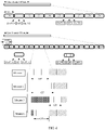
- Table 1 is a TDD configuration table of an existing TDD LTE system. As shown in Table 1, in the existing TDD LTE system, there are a total of seven types of TDD configurations: 0 to 6. In the table, “D” represents a downlink subframe, “S” represents a special subframe (S subframe), and “U” represents an uplink subframe (in the following descriptions, meanings of "S", “D”, and “U” are the same as the definitions herein, and explanation is not repeated).
- FIG. 1 is a structural diagram of an existing subframe.
- An embodiment of the present invention provides a communication method in a time division duplex system. As shown in FIG. 2 , the method includes the following steps:
- the UE after a base station sends downlink data to UE in a downlink subframe, the UE needs to send, after receiving the downlink data, feedback information of downlink-data reception to the base station in a subsequent uplink subframe.
- the UE after UE receives, in a downlink subframe, downlink data sent by a base station, because at least one of at least two consecutive downlink subframes is configured as a first subframe, the UE can send feedback information of downlink-data reception to the base station in the first subframe, instead of waiting until a subsequent uplink subframe to send the feedback information of downlink-data reception to the base station.
- At least one of at least two consecutive uplink subframes is configured as a second subframe, and the base station can send feedback information to the UE in the second subframe, instead of waiting until a downlink subframe to send the feedback information to the UE.
- a time interval for waiting for UL/DL switching is shortened, and a system RTT is shortened.
- the base station may send the determined radio frame configuration information to the UE specifically in the following manner:
- the base station sends the radio frame configuration information to the UE by using a broadcast message; or the base station sends the radio frame configuration information to the UE by using radio resource control RRC dedicated signaling, Media Access Control MAC signaling, or physical downlink control channel PDCCH signaling.
- RRC dedicated signaling Media Access Control MAC signaling, or physical downlink control channel PDCCH signaling.
- the first subframe includes a guard period and at least one first symbol used for uplink service transmission, and the guard period precedes the first symbol.
- the first subframe may be used for uplink synchronization and uplink and downlink isolation.
- the first subframe further includes at least one second symbol used for downlink service transmission, and the second symbol precedes the guard period.
- the second symbol used for downlink service transmission may be specifically used to send a physical downlink control channel (Physical Downlink Control Channel, PDCCH for short), and may be further used to send a physical downlink shared channel (Physical Downlink Shared Channel, PDSCH for short).
- the first symbol used for uplink service transmission may be used to send a sounding reference signal (Sounding Reference Signal, SRS) or a physical random access channel (Physical Random Access Channel, PRACH for short) signal.
- SRS Sounding Reference Signal
- PRACH Physical Random Access Channel
- the guard period is used to isolate the symbol used for uplink service transmission from the symbol used for downlink service transmission, so as to prevent a channel from generating uplink interference to another remote station, determine a coverage area, and further ensure that terminal signals synchronously arrive at the base station.
- the base station may indicate the first subframe as an MBMS subframe. That the base station communicates with the UE by using a radio frame configured according to the radio frame configuration information may specifically include: The base station transmits MBMS data to the UE by using the indicated MBMS subframe. In this way, first UE that uses a TTI equal to 1 ms does not receive data any more after receiving a downlink control channel in N symbols in the first subframe.
- the base station may further send a common reference signal to the UE by using the first subframe of the configured radio frame, so as to facilitate signal measurement by the UE. In this case, the UE can obtain all required scheduling information and the like from the first few symbols in the MBMS subframe.
- the first UE that uses a TTI equal to 1 ms does not receive data any more after receiving a downlink control channel in the first N symbols in the first subframe.
- Second UE that uses a TTI less than 1 ms (for example, 0.5 ms) may receive other data in a remaining time of the first subframe if the second UE detects downlink scheduling information for the second UE in the first few symbols in the first subframe. Therefore, compatibility between the first UE and the second UE is ensured, and mutual interference between new-version and old-version UEs that use different TTIs is avoided.
- 1 ms for example, 0.5 ms
- the second subframe includes a guard period and at least one third symbol used for downlink service transmission, and the guard period is preceded by the third symbol.
- the second subframe further includes at least one fourth symbol used for uplink service transmission, and the fourth symbol is preceded by the guard period.
- the second symbol used for downlink service transmission may be specifically used to send a PDCCH signal, and may be further used to send a PDSCH signal.
- the first symbol used for uplink service transmission may be used to send an SRS or a PRACH signal.
- the guard period is used to isolate the symbol used for uplink service transmission from the symbol used for downlink service transmission, so as to prevent a channel from generating uplink interference to another remote station, determine a coverage area, and further ensure that terminal signals synchronously arrive at the base station.
- the base station may further send the radio frame configuration information, a radio frame period length, a determined TTI, and other information to another base station, so that each base station determines a location of a subframe used by the base station to communicate with a terminal. This can avoid transmission interference between base stations.
- radio frame configuration information is used to instruct the UE to set at least one of N consecutive downlink subframes of one radio frame as a first subframe
- descriptions are provided as follows: (1)
- radio frame duration is unchanged, duration of each subframe is also unchanged, and one subframe includes 14 symbols.
- a TTI is equal to the subframe duration.
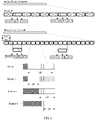
- radio frame configuration at least one of not less than two consecutive downlink subframes of one radio frame is configured as a first subframe, that is, as shown in Table 2, a group of DL switch points are added to each radio frame. This reduces a time interval for waiting for UL/DL switching in some subframes, thereby reducing a system RTT.
- "X" represents the first subframe.
- the first subframe may be configured in, but not limited to, the following manners, as shown in FIG. 3 (the figure shows merely an example and does not impose any specific limitation on the solutions provided in the embodiments of the present invention):
- the radio frame duration is kept unchanged and is still 10 ms, and the subframe duration is reduced to 1/n of the original subframe duration, where n>1, and n is a positive integer.
- the subframe may be evenly divided into n parts, and a use of a symbol that occupies each part is unchanged.
- the first seven symbols are duration of one subframe and are altogether used as a guard period, and the last seven symbols are an uplink pilot timeslot and used as one subframe that may be considered as an uplink subframe.
- the other manners are shown in FIG. 4 .
- the radio frame duration may be unchanged and still be 10 ms, and the subframe duration may be unchanged.
- the transmission time interval TTI is shortened.
- a shortened TTI is 0.5 ms.
- Manner 4 for the configured first subframe, the first few symbols in a current TTI are used for downlink service transmission, and a next TTI is used as an uplink subframe for uplink service transmission.
- radio frame duration is unchanged and is still 10 ms, and subframe duration may be reduced to 1/n of the original subframe duration, where n>1, and n is optionally an integer. Based on reduction of the subframe duration, at least one of not less than two consecutive downlink subframes may be configured as the first subframe.
- the configured first subframe includes a guard period and at least one first symbol used for uplink service transmission, and the guard period precedes the first symbol.
- the configured first subframe further includes at least one second symbol used for downlink service transmission, and the second symbol precedes the guard period.
- n 2.
- subframe duration is 0.5 ms.
- a TTI length is equal to the subframe duration, that is, 0.5 ms.
- a symbol length is the same as that in an existing TDD LTE system.
- subframes are numbered in a numbering manner that is the same as that in an existing TDD system. That is, in one radio frame, subframes are numbered from 0. In one radio frame, the first subframe is a subframe 0, the second subframe is a subframe 1, and so on. Explanation is not repeated hereinafter.
- duration of an S subframe in Table 3 may be modified.
- a small-coverage scenario that is, a cell coverage radius is not greater than a preset coverage radius threshold
- only a subframe 2 may be set as an S subframe
- a subframe 3 may be set as an uplink subframe.
- a radio frame of 10 ms a subframe 2 and a subframe 12 are S subframes, and a subframe 3 and a subframe 13 are changed into uplink subframes.
- a large-coverage scenario that is, a cell coverage radius is greater than a preset coverage radius threshold
- multiple consecutive subframes may need to be occupied as an S subframe.
- the configuration manner in Table 3 may be used, and two consecutive subframes are occupied as the S subframe.
- At least one of not less than two consecutive downlink subframes is configured as a first subframe.
- the first subframe may further occupy locations of two shortened subframes.
- a current TTI is used for downlink service transmission, including UL data scheduling.
- a next TTI is used for uplink service transmission, for example, UL data sending or UL feedback for DL data.
- a time sequence for sending UL data is as follows:
- a time sequence for sending DL data is as follows:
- radio frame configuration information is used to instruct the UE to set at least one of M consecutive uplink subframes of one radio frame as a second subframe
- radio frame duration is unchanged, duration of each subframe is also unchanged, and one subframe includes 14 symbols.
- a TTI is equal to the subframe duration.
- radio frame configuration at least one of not less than two consecutive uplink subframes of one radio frame is configured as a second subframe. That is, as shown in Table 8, a TTI is equal to, for example, 1 ms, and the TTI length is equal to subframe duration, and a group of DL switch points are added to each radio frame.
- E represents the second subframe.
- Table 8 TDD configuration Downlink-to- uplink switch-point period Subframe number 0 1 2 3 4 5 6 7 8 9 7 (originally 0) 5 ms D S U E U D S U U U 13 (originally 6) 10 ms D S U E U D S U U D
- the second subframe may be configured in, but not limited to, the following manners, as shown in FIG. 5 (the figure shows merely an example and does not impose any specific limitation on the solutions provided in the embodiments of the present invention):
- the radio frame duration is kept unchanged and is still 10 ms, and the subframe duration is reduced to 1/n of the original subframe duration, where n>1, and n is a positive integer.
- the subframe may be evenly divided into n parts, and a use of a symbol that occupies each part is unchanged.
- the first seven symbols are a downlink pilot timeslot and used as one subframe that may be considered as a downlink subframe, and the last seven symbols are duration of one subframe and are altogether used as a guard period.
- the other manners are shown in FIG. 5 .
- the radio frame duration may be unchanged and still be 10 ms, and the subframe duration may be unchanged.
- the transmission time interval TTI is shortened.
- a shortened TTI is 0.5 ms.
- the first few symbols in a current TTI are used for downlink service transmission, and a next TTI may be considered as an uplink subframe and is used for uplink service transmission.
- radio frame duration is unchanged and is still 10 ms, and subframe duration may be reduced to 1/n of the original subframe duration, where n>1, and n is optionally an integer.
- At least one of not less than two consecutive downlink subframes may be configured as the first subframe.
- the second subframe includes a guard period and at least one third symbol used for downlink service transmission, and the guard period is preceded by the third symbol.
- the second subframe further includes at least one fourth symbol used for uplink service transmission, and the fourth symbol is preceded by the guard period.
- n 2.
- subframe duration is 0.5 ms.
- a TTI length is equal to the subframe duration, that is, 0.5 ms.
- a symbol length is the same as that in an existing TDD LTE system.
- duration of an S subframe in Table 3 may be modified.
- a small-coverage scenario that is, a cell coverage radius is not greater than a preset coverage radius threshold
- only a subframe 2 may be set as an S subframe
- a subframe 3 may be set as an uplink subframe.
- a radio frame of 10 ms a subframe 2 and a subframe 12 are S subframes, and a subframe 3 and a subframe 13 are changed into uplink subframes.
- a large-coverage scenario that is, a cell coverage radius is greater than a preset coverage radius threshold
- multiple consecutive subframes may need to be occupied as an S subframe.
- the configuration manner in Table 3 may be used, and two consecutive subframes are occupied as the S subframe.
- At least one of not less than two consecutive uplink subframes may be configured as a second subframe for downlink service transmission or for downlink service transmission and uplink service transmission.
- a group of DL switch points are added to each radio frame. This reduces a time interval for waiting for UL/DL switching in some subframes, thereby reducing a system RTT.
- the second subframe may further occupy locations of two shortened sub frames, and the TTI is equal to 0.5 ms.
- a current TTI is used as a DL subframe for sending (a DL grant+DL data) or for sending a UL grant, and a next TTI is used as the GP.
- a current TTI is used for DL data and a DL grant/a UL grant.
- the first few symbols in a next TTI are used only for a PDCCH.
- the GP is used for DL-to-UL switching.
- the first few symbols in a current TTI are used for downlink service transmission, and the last few symbols of a next TTI are used for uplink service transmission.
- a PDCCH symbol that occupies several symbols exists in the current TTI (0.5 ms) and is used for sending a UL grant
- the GP that occupies several symbols exists in the middle
- a timeslot of the next TTI (0.5 ms) is used as a hold UL subframe for sending UL data.
- a GP length may be determined according to a cell coverage radius. If the cell coverage radius is greater than a preset coverage radius threshold, the special subframe may be configured in Manner 1. If the cell coverage radius is less than a preset coverage radius threshold, the special subframe may be configured in any one of Manner 2 to Manner 4.
- the base station communicates with the UE by using a radio frame configured according to the radio frame configuration information may be specifically receiving, by using the uplink pilot timeslot in the second subframe, uplink control information and/or uplink data sent by the UE.
- the uplink control information includes at least one of uplink reply information, uplink scheduling information, or channel state information.
- the base station is further configured to determine a time sequence of an HARQ process for performing data transmission with the UE, and perform data transmission with the UE in the determined time sequence of the HARQ process.
- a time sequence for sending UL data is as follows:
- Step 1 Send UL scheduling information in a DL subframe (subframe duration herein is 0.5 ms) n, where the information includes UL grant information. It is assumed that a sending time is a TTI n.
- Step 2 After receiving a UL grant, UE sends UL data in a TTI n+k, where k is greater than or equal to four TTIs, and the subframe n+k is a UL subframe.
- k is greater than or equal to four TTIs
- the subframe n+k is a UL subframe.
- Table 10 Value settings of k are described by using the subframe configuration in Table 9 as an example).
- Step 3 An eNB sends a DL feedback for the UL data in a subframe n+k+kl, where k1 is greater than or equal to four TTIs, and the subframe n+k+k1 is a DL subframe.
- k1 is greater than or equal to four TTIs
- the subframe n+k+k1 is a DL subframe.
- Table 11 values of k1 are described by using the subframe configuration in Table 9 as an example).
- Step 4 If the eNB feeds back an NCK in the subframe n+k+kl, the UE performs retransmission in a subframe n+k+k1+k.
- a time sequence for sending DL data is as follows:
- an embodiment of the present invention further provides another communication method in a time division duplex system. Content the same as that of the embodiment shown in FIG. 2 is not repeated herein. As shown in FIG. 6 , the method includes the following steps:
- the UE after UE receives, in a downlink subframe, downlink data sent by a base station, the UE needs to send feedback information of downlink-data reception to the base station in a subsequent uplink subframe.
- the UE after UE receives, in a downlink subframe, downlink data sent by a base station, because at least one of at least two consecutive downlink subframes is configured as a first subframe, the UE can send feedback information of downlink-data reception to the base station in the first subframe, instead of waiting until a subsequent uplink subframe to send the feedback information of downlink-data reception to the base station.
- the UE can receive feedback information from the base station in the second subframe, instead of waiting until a subsequent downlink subframe to receive the feedback information from the base station. In this way, a time interval for waiting for UL/DL switching is shortened, and a system RTT is shortened.
- the first subframe includes a guard period and at least one first symbol used for uplink service transmission, and the guard period precedes the first symbol.
- the first subframe further includes at least one second symbol used for downlink service transmission, and the second symbol precedes the guard period.
- the second subframe includes a guard period and at least one third symbol used for downlink service transmission, and the guard period is preceded by the third symbol.
- the second subframe further includes at least one fourth symbol used for uplink service transmission, and the fourth symbol is preceded by the guard period.
- An embodiment of the present invention further provides a base station.
- the base station includes:
- the first subframe includes a guard period and at least one first symbol used for uplink service transmission, and the guard period precedes the first symbol.
- the first subframe further includes at least one second symbol used for downlink service transmission, and the second symbol precedes the guard period.
- the second subframe includes a guard period and at least one third symbol used for downlink service transmission, and the guard period is preceded by the third symbol.
- the second subframe further includes at least one fourth symbol used for uplink service transmission, and the fourth symbol is preceded by the guard period.
- the sending unit 702 is specifically configured to:
- An embodiment of the present invention provides user equipment. As shown in FIG. 8 , the user equipment includes:
- the first subframe includes a guard period and at least one first symbol used for uplink service transmission, and the guard period precedes the first symbol.
- the first subframe further includes at least one second symbol used for downlink service transmission, and the second symbol precedes the guard period.
- the second subframe includes a guard period and at least one third symbol used for downlink service transmission, and the guard period is preceded by the third symbol.
- the second subframe further includes at least one fourth symbol used for uplink service transmission, and the fourth symbol is preceded by the guard period.
- unit division in the embodiments of the present invention is an example and is merely a logical function division. In actual implementation, there may be another division manner, or some features may be ignored or may not be performed.
- functional units in the embodiments of this application may be integrated into one processing unit, or each of the units may exist alone physically, or two or more units may be integrated into one unit.
- the integrated unit may be implemented in a form of hardware, or may be implemented in a form of a software function unit.
- the integrated unit When the integrated unit is implemented in the form of a software function unit and sold or used as an independent product, the integrated unit may be stored in a computer-readable storage medium. Based on such an understanding, the technical solutions of this application essentially, or the part contributing to the prior art, or all or a part of the technical solutions may be implemented in a form of a software product.
- the computer software product is stored in a storage medium and includes several instructions for instructing a computer device (which may be a personal computer, a server, a network device, or the like) or a processor (processor) to perform all or a part of the steps of the methods in the embodiments of this application.
- the foregoing storage medium includes any medium that can store program code, such as a USB flash drive, a removable hard disk, a read-only memory (ROM, Read-Only Memory), a random access memory (RAM, Random Access Memory), a magnetic disk, or an optical disc.
- program code such as a USB flash drive, a removable hard disk, a read-only memory (ROM, Read-Only Memory), a random access memory (RAM, Random Access Memory), a magnetic disk, or an optical disc.
- An embodiment of the present invention further provides a base station.
- the base station includes: a transceiver 901, a processor 902, a bus 903, and a memory 904.
- the transceiver 901, the processor 902, and the memory 904 are connected to each other by using the bus 903.
- the bus 903 may be a peripheral component interconnect (peripheral component interconnect, PCI for short) bus, an extended industry standard architecture (extended industry standard architecture, EISA for short) bus, or the like.
- the bus may be classified into an address bus, a data bus, a control bus, and the like. For convenience of denotation, the bus is represented by using only one bold line in FIG. 9 ; however, it does not indicate that there is only one bus or only one type of bus.
- the memory 904 is configured to store an executable program.
- the processor 902 is configured to execute the executable program stored in the memory 904, to execute the following:
- the first subframe includes a guard period and at least one first symbol used for uplink service transmission, and the guard period precedes the first symbol.
- the first subframe further includes at least one second symbol used for downlink service transmission, and the second symbol precedes the guard period.
- the second subframe includes a guard period and at least one third symbol used for downlink service transmission, and the guard period is preceded by the third symbol.
- the second subframe further includes at least one fourth symbol used for uplink service transmission, and the fourth symbol is preceded by the guard period.
- the transceiver 901 is specifically configured to:
- the user equipment includes: a transceiver 1001, a processor 1002, a bus 1003, and a memory 1004.
- the transceiver 1001, the processor 1002, and the memory 1004 are connected to each other by using the bus 1003.
- the bus 1003 may be a peripheral component interconnect (peripheral component interconnect, PCI for short) bus, an extended industry standard architecture (extended industry standard architecture, EISA for short) bus, or the like.
- the bus may be classified into an address bus, a data bus, a control bus, and the like.
- the bus is represented by using only one bold line in FIG. 10 ; however, it does not indicate that there is only one bus or only one type of bus.
- the memory 1004 is configured to store an executable program.
- the processor 1002 is configured to execute the executable program stored in the memory 1004, to execute the following: receiving, by the transceiver 1001, radio frame configuration information sent by a base station; according to the radio frame configuration information received by the transceiver 1001, determining, by the processor 1002, that at least one of N consecutive downlink subframes of one radio frame is configured as a first subframe, and/or determining that at least one of M consecutive uplink subframes of one radio frame is configured as a second subframe, where the first subframe is used for uplink service transmission, the second subframe is used for downlink service transmission, and N and M are positive integers not less than 2; and communicating with the base station by using a radio frame determined according to the radio frame configuration information.
- the first subframe includes a guard period and at least one first symbol used for uplink service transmission, and the guard period precedes the first symbol.
- the first subframe further includes at least one second symbol used for downlink service transmission, and the second symbol precedes the guard period.
- the second subframe includes a guard period and at least one third symbol used for downlink service transmission, and the guard period is preceded by the third symbol.
- the second subframe further includes at least one fourth symbol used for uplink service transmission, and the fourth symbol is preceded by the guard period.
- These computer program instructions may be provided for a general-purpose computer, a dedicated computer, an embedded processor, or a processor of any other programmable data processing device to generate a machine, so that the instructions executed by a computer or a processor of any other programmable data processing device generate an apparatus for implementing a specific function in one or more processes in the flowcharts and/or in one or more blocks in the block diagrams.
- These computer program instructions may be stored in a computer readable memory that can instruct the computer or any other programmable data processing device to work in a specific manner, so that the instructions stored in the computer readable memory generate an artifact that includes an instruction apparatus.
- the instruction apparatus implements a specified function in one or more processes in the flowcharts and/or in one or more blocks in the block diagrams.
- These computer program instructions may also be loaded onto a computer or another programmable data processing device, so that a series of operations and steps are performed on the computer or the another programmable device, thereby generating computer-implemented processing. Therefore, the instructions executed on the computer or the another programmable device provide steps for implementing a specific function in one or more processes in the flowcharts and/or in one or more blocks in the block diagrams.
Description
- The present invention relates to the field of communications technologies, and in particular, to a communication method in a time division duplex system, a base station, and user equipment.
- A Long Term Evolution (Long Term Evolution, LTE for short) system supports a time division duplex (Time Division Duplexing, TDD for short) manner. That is, an uplink (Uplink, UL for short) and a downlink (Downlink, DL for short) use different timeslots of a same carrier. The uplink is used for uplink communication. That is, if user equipment (User Equipment, UE for short) has data to be sent to a base station, the user sends the data by using the uplink. The downlink is used for downlink communication. That is, if a base station has data to be sent to a user, the base station sends the data by using the downlink.
- A round-trip latency (Round Trip Time, RTT) is an important indicator for measuring performance of a wireless communications system, and generally means a period from a time at which a transmit end sends data to a time at which the transmit end receives an acknowledgement from a receive end.
- In a TDD system, data scheduling is generally performed in a hybrid automatic repeat request HARQ (Hybrid Automatic Repeat Request, HARQ) manner. For one HARQ process, after sending data, a transmit end does not send a next data packet until a preset maximum feedback latency elapses. Therefore, if an ACK can be received as soon as possible, a time interval at which data packets are sent in one HARQ process can be shortened, an RTT can be reduced, and data transmission efficiency can be improved.
- Currently, there is still no method that can effectively reduce an RTT of a TDD communications system and improve data transmission efficiency.
-
WO 2013/141770 A1 discloses technology that provides the ability for a subframe to be dynamically configured in TDD communications between a UE radio terminal and a radio network node. A frame structure includes one or more subframes preconfigured as a downlink subframe, one or more subframes preconfigured as an uplink subframe, and one or more dynamically configurable subframes. Each dynamically configurable subframe includes a guard time period and at least a downlink part for transporting a dynamically configurable amount of downlink information. A configuration for dynamically configurable subframes is determined for transmission and/or reception between the UE radio terminal and the radio network node. -
US 2014/293842 A1 discloses methods and apparatuses related to receiving one or more indications of TDD uplink/downlink (UL/DL) configurations for two consecutive radio frames. Based on the indications of the TDD UL/DL configurations, a reference TDD UL/DL configuration may be identified for one or more hybrid automatic repeat request (HARQ) processes. - The present invention provides communication methods of
claims claim 7, user equipment ofclaim 10 and related computer-readable storage mediums ofclaims 13 and 14, so as to effectively reduce an RTT and improve data transmission efficiency. Possible implementation manners are disclosed in the dependent claims. - According to a first aspect, an embodiment of the present invention provides a communication method in a time division duplex system, where the method includes:
- determining, by a base station, radio frame configuration information;
- sending, by the base station, the determined radio frame configuration information to user equipment UE; and
- communicating, by the base station, with the UE by using a radio frame configured according to the radio frame configuration information;
- wherein the radio frame configuration information instructs the UE to at least one of:
- configure each of uplink subframe of one radio frame to two same consecutive uplink subframe based on a reduction of a subframe duration, wherein a subframe duration of each of the two same consecutive uplink subframe is 1/2 of an original subframe duration of each of the uplink subframe before the configuring;
- configure each of downlink subframe of one radio frame to two same consecutive downlink subframe based on a reduction of a subframe duration, wherein a subframe duration of each of the two same consecutive downlink subframe is 1/2 of an original subframe duration of each of the downlink subframe before the configuring;
- configure each of special subframe of one radio frame to two same consecutive special subframe based on a reduction of a subframe duration, wherein a subframe duration of each of the two same consecutive special subframe is 1/2 of an original subframe duration of each of the special subframe before the configuring.
- According to a second aspect, an embodiment of the present invention further provides a communication method in a time division duplex system, where the method includes:
- receiving, by user equipment UE, radio frame configuration information sent by a base station; and
- communicating, by the UE, with the base station by using a radio frame determined according to the radio frame configuration information;
- wherein the radio frame configuration information instructs the UE to at least one of:
- configure each of uplink subframe of one radio frame to two same consecutive uplink subframe based on a reduction of a subframe duration, wherein a subframe duration of each of the two same consecutive uplink subframe is 1/2 of an original subframe duration of each of the uplink subframe before the configuring;
- configure each of downlink subframe of one radio frame to two same consecutive downlink subframe based on a reduction of a subframe duration, wherein a subframe duration of each of the two same consecutive downlink subframe is 1/2 of an original subframe duration of each of the downlink subframe before the configuring;
- configure each of special subframe of one radio frame to two same consecutive special subframebased on a reduction of a subframe duration, wherein a subframe duration of each of the two same consecutive special subframe is 1/2 of an original subframe duration of each of the special subframe before the configuring.
- According to a third aspect, an embodiment of the present invention further provides a base station configured to perform the communication method of the first aspect.
- According to a fourth aspect, an embodiment of the present invention further provides user equipment configured to perform the communication method of the second aspect.
- According to the embodiments of the present invention, in a TDD system, radio frame duration is kept unchanged, and in radio frame configuration, at least one of not less than two consecutive downlink subframes of one radio frame is configured as a first subframe, and/or at least one of not less than two consecutive uplink subframes of one radio frame is configured as a second sub frame, where the first sub frame is used for uplink service transmission, and the second subframe is used for downlink service transmission. That is, a group of DL switch points are added to each radio frame. This reduces a time interval for waiting for UL/DL switching in some subframes, thereby reducing a system RTT. For example, after UE receives, in a downlink subframe, downlink data sent by a base station, the UE needs to send feedback information of downlink-data reception to the base station in a subsequent uplink subframe. According to the method provided in the present invention, after UE receives, in a downlink subframe, downlink data sent by a base station, because at least one of at least two consecutive downlink subframes is configured as a first subframe, the UE can send feedback information of downlink-data reception to the base station in the first subframe, instead of waiting until a subsequent downlink subframe to send the feedback information of downlink-data reception to the base station. Therefore, a time interval for waiting for UL/DL switching is shortened, thereby shortening a system RTT.
-
-
FIG. 1 is a schematic structural diagram of a TDD subframe according to an embodiment of the present invention; -
FIG. 2 is a flowchart of a communication method in a time division duplex system according to an embodiment of the present invention; -
FIG. 3 is a schematic structural diagram of a first subframe according to an embodiment of the present invention; -
FIG. 4 is a schematic structural diagram of another TDD subframe according to an embodiment of the present invention; -
FIG. 5 is a schematic structural diagram of still another TDD subframe according to an embodiment of the present invention; -
FIG. 6 is a flowchart of another communication method in a time division duplex system according to an embodiment of the present invention; -
FIG. 7 is a schematic structural diagram of a base station according to an embodiment of the present invention; -
FIG. 8 is a schematic structural diagram of user equipment according to an embodiment of the present invention; -
FIG. 9 is a schematic structural diagram of another base station according to an embodiment of the present invention; and -
FIG. 10 is a schematic structural diagram of another user equipment according to an embodiment of the present invention. - To make the objectives, technical solutions, and advantages of the present invention clearer, the following further describes the present invention in detail with reference to the accompanying drawings. Apparently, the described embodiments are merely some rather than all of the embodiments of the present invention. All other embodiments obtained by a person of ordinary skill in the art based on the embodiments of the present invention without creative efforts shall fall within the protection scope of the present invention.
- The embodiments of the present invention provide a communication method in a time division duplex system, a base station, and user equipment, so as to effectively reduce an RTT and improve data transmission efficiency. The method and the apparatuses are based on a same invention idea. Because similar principles are used by the method and the apparatuses to resolve a problem, implementations of the apparatuses and the method may be cross-referenced, and repetition is omitted herein.
- In the embodiments of the present invention, a TDD LTE system is used as an example for description. However, this does not mean that the embodiments of the present invention are applicable only to TDD LTE systems.
- In TDD LTE systems, TDD configuration is a very important concept. Various channel configurations are implemented according to specific TDD configurations. Therefore, TDD configurations in an existing TDD LTE system are first described before the embodiments of the present invention are described.
- Table 1 is a TDD configuration table of an existing TDD LTE system. As shown in Table 1, in the existing TDD LTE system, there are a total of seven types of TDD configurations: 0 to 6. In the table, "D" represents a downlink subframe, "S" represents a special subframe (S subframe), and "U" represents an uplink subframe (in the following descriptions, meanings of "S", "D", and "U" are the same as the definitions herein, and explanation is not repeated). In Table 1, downlink-to-uplink switch-point periods (Downlink-to-Uplink Switch-point periodicity) of the
TDD configurations TDD configurations 3 to 5 are 10 ms.FIG. 1 is a structural diagram of an existing subframe.Table 1 TDD configuration Downlink-to- uplink switch-point period Subframe number 0 1 2 3 4 5 6 7 8 9 0 5 ms D S U U U D S U U U 1 5 ms D S U U D D S U U D 2 5 ms D S U D D D S U D D 3 10 ms D S U U U D D D D D 4 10 ms D S U U D D D D D D 5 10 ms D S U D D D D D D D 6 5 ms D S U U U D S U U D - The following specifically describes the embodiments of the present invention with reference to the accompanying drawings.
- An embodiment of the present invention provides a communication method in a time division duplex system. As shown in
FIG. 2 , the method includes the following steps: - Step 201: Abase station determines radio frame configuration information.
- Step 202: The base station sends the determined radio frame configuration information to user equipment UE, where the radio frame configuration information is used to instruct the UE to set at least one of N consecutive downlink subframes of one radio frame as a first subframe, and/or the radio frame configuration information is used to instruct the UE to set at least one of M consecutive uplink subframes of one radio frame as a second subframe, where the first subframe is used for uplink service transmission, the second subframe is used for downlink service transmission, and N and M are positive integers not less than 2.
- Step 203: The base station communicates with the UE by using a radio frame configured according to the radio frame configuration information.
- According to the method provided in the foregoing embodiment, after a base station sends downlink data to UE in a downlink subframe, the UE needs to send, after receiving the downlink data, feedback information of downlink-data reception to the base station in a subsequent uplink subframe. According to the method provided in the present invention, after UE receives, in a downlink subframe, downlink data sent by a base station, because at least one of at least two consecutive downlink subframes is configured as a first subframe, the UE can send feedback information of downlink-data reception to the base station in the first subframe, instead of waiting until a subsequent uplink subframe to send the feedback information of downlink-data reception to the base station. Alternatively, after UE sends uplink data to a base station in an uplink subframe, according to the method provided in this embodiment of the present invention, at least one of at least two consecutive uplink subframes is configured as a second subframe, and the base station can send feedback information to the UE in the second subframe, instead of waiting until a downlink subframe to send the feedback information to the UE. In this way, a time interval for waiting for UL/DL switching is shortened, and a system RTT is shortened.
- Optionally, the base station may send the determined radio frame configuration information to the UE specifically in the following manner:
- The base station sends the radio frame configuration information to the UE by using a broadcast message; or
the base station sends the radio frame configuration information to the UE by using radio resource control RRC dedicated signaling, Media Access Control MAC signaling, or physical downlink control channel PDCCH signaling. - Optionally, the first subframe includes a guard period and at least one first symbol used for uplink service transmission, and the guard period precedes the first symbol.
- The first subframe may be used for uplink synchronization and uplink and downlink isolation.
- Specifically, the first subframe includes C symbols, where the first x symbols are the guard period, the last y symbols are an uplink pilot timeslot used for uplink service transmission, x=C/2, and y=C/2; or
the first subframe includes C symbols, where the first x symbols are the guard period, the last y symbols are an uplink pilot timeslot used for uplink service transmission, C=x+y, and x>C/2. - Further, the first subframe further includes at least one second symbol used for downlink service transmission, and the second symbol precedes the guard period.
- Specifically, the first subframe includes C symbols, where the first x symbols are a downlink pilot timeslot used for downlink service transmission, the last y symbols are an uplink pilot timeslot used for uplink service transmission, the middle z symbols are the guard period, C=x+y+z, and x≤C/2; or
the first subframe includes C symbols, where the first x symbols are a downlink pilot timeslot used for downlink service transmission, the last y symbols are an uplink pilot timeslot used for uplink service transmission, the middle z symbols are the guard period, C=x+y+z, x<C/2, and y=C/2. - In the first subframe, the second symbol used for downlink service transmission may be specifically used to send a physical downlink control channel (Physical Downlink Control Channel, PDCCH for short), and may be further used to send a physical downlink shared channel (Physical Downlink Shared Channel, PDSCH for short). The first symbol used for uplink service transmission may be used to send a sounding reference signal (Sounding Reference Signal, SRS) or a physical random access channel (Physical Random Access Channel, PRACH for short) signal. The guard period is used to isolate the symbol used for uplink service transmission from the symbol used for downlink service transmission, so as to prevent a channel from generating uplink interference to another remote station, determine a coverage area, and further ensure that terminal signals synchronously arrive at the base station.
- Optionally, the base station may indicate the first subframe as an MBMS subframe. That the base station communicates with the UE by using a radio frame configured according to the radio frame configuration information may specifically include: The base station transmits MBMS data to the UE by using the indicated MBMS subframe. In this way, first UE that uses a TTI equal to 1 ms does not receive data any more after receiving a downlink control channel in N symbols in the first subframe. When the base station communicates with the UE by using the radio frame configured according to the radio frame configuration information, the base station may further send a common reference signal to the UE by using the first subframe of the configured radio frame, so as to facilitate signal measurement by the UE. In this case, the UE can obtain all required scheduling information and the like from the first few symbols in the MBMS subframe.
- For example, the first subframe includes C symbols, where the first x symbols are a downlink pilot timeslot used for downlink service transmission, the last y symbols are an uplink pilot timeslot used for uplink service transmission, the middle z symbols are the guard period, C=x+y+z, x<C/2, y=C/2, and C=14. The first UE that uses a TTI equal to 1 ms does not receive data any more after receiving a downlink control channel in the first N symbols in the first subframe. Second UE that uses a TTI less than 1 ms (for example, 0.5 ms) may receive other data in a remaining time of the first subframe if the second UE detects downlink scheduling information for the second UE in the first few symbols in the first subframe. Therefore, compatibility between the first UE and the second UE is ensured, and mutual interference between new-version and old-version UEs that use different TTIs is avoided.
- Optionally, the second subframe includes a guard period and at least one third symbol used for downlink service transmission, and the guard period is preceded by the third symbol.
- Specifically, the second subframe includes P symbols, where the first a symbols are a downlink pilot timeslot used for downlink service transmission, the last b symbols are the guard period, a=P/2, and b=P/2; or
the second subframe includes P symbols, where the first a symbols are a downlink pilot timeslot used for downlink service transmission, the last b symbols are the guard period, P=a+b, and a>P/2. - Further, the second subframe further includes at least one fourth symbol used for uplink service transmission, and the fourth symbol is preceded by the guard period.
- Specifically, the second subframe includes P symbols, where the first a symbols are a downlink pilot timeslot used for downlink service transmission, the last b symbols are an uplink pilot timeslot used for uplink service transmission, the middle w symbols are the guard period, P=a+b+w, and a≤P/2; or
the second subframe includes P symbols, where the first a symbols are a downlink pilot timeslot used for downlink service transmission, the last b symbols are an uplink pilot timeslot used for uplink service transmission, the middle w symbols are the guard period, P=a+b+w, a<P/2, and b=P/2. - In the second subframe, the second symbol used for downlink service transmission may be specifically used to send a PDCCH signal, and may be further used to send a PDSCH signal. The first symbol used for uplink service transmission may be used to send an SRS or a PRACH signal. The guard period is used to isolate the symbol used for uplink service transmission from the symbol used for downlink service transmission, so as to prevent a channel from generating uplink interference to another remote station, determine a coverage area, and further ensure that terminal signals synchronously arrive at the base station.
- The base station may further send the radio frame configuration information, a radio frame period length, a determined TTI, and other information to another base station, so that each base station determines a location of a subframe used by the base station to communicate with a terminal. This can avoid transmission interference between base stations.
- For a case in which the radio frame configuration information is used to instruct the UE to set at least one of N consecutive downlink subframes of one radio frame as a first subframe, descriptions are provided as follows:
(1) In a TDD system, radio frame duration is unchanged, duration of each subframe is also unchanged, and one subframe includes 14 symbols. A TTI is equal to the subframe duration. In radio frame configuration, at least one of not less than two consecutive downlink subframes of one radio frame is configured as a first subframe, that is, as shown in Table 2, a group of DL switch points are added to each radio frame. This reduces a time interval for waiting for UL/DL switching in some subframes, thereby reducing a system RTT. In Table 2, "X" represents the first subframe.Table 2 TDD configuration Downlink-to-uplink switch-point period Subframe number 0 1 2 3 4 5 6 7 8 9 7 (originally 2) 5 ms D S U D X D S U D D 8 (originally 3) 10 ms D S U U U D D X D D 9 (originally 4) 10 ms D S U U D D X D D D 10 (originally 5) 10 ms D S U D D D D X D D - The first subframe may be configured in, but not limited to, the following manners, as shown in
FIG. 3 (the figure shows merely an example and does not impose any specific limitation on the solutions provided in the embodiments of the present invention): - Manner 1: The first seven symbols in the first subframe are a guard period, and the last seven symbols are an uplink pilot timeslot used for uplink service transmission.
- Manner 2: The first x symbols in the first subframe are a guard period, and the last y symbols are an uplink pilot timeslot used for uplink service transmission, where 14=x+y, and x>7.
- Manner 3: The first x symbols in the first subframe are a downlink pilot timeslot used for downlink service transmission, the last y symbols are an uplink pilot timeslot used for uplink service transmission, and the middle z symbols are a guard period, where 14=x+y+z, and x≤7.
- Manner 4: The first x symbols in the first subframe are a downlink pilot timeslot used for downlink service transmission, the last y symbols are an uplink pilot timeslot used for uplink service transmission, and the middle z symbols are a guard period, where 14=x+y+z, x<7, and y=7.
- Optionally, by means of the configuration described above, the radio frame duration is kept unchanged and is still 10 ms, and the subframe duration is reduced to 1/n of the original subframe duration, where n>1, and n is a positive integer. The subframe may be evenly divided into n parts, and a use of a symbol that occupies each part is unchanged. The TTI is equal to the subframe duration. For example, n=2. In this case, after a change, an uplink subframe becomes two uplink subframes, and a downlink subframe becomes two downlink subframes. Based on the
foregoing Manner 1 in which the first subframe is configured, the first seven symbols are duration of one subframe and are altogether used as a guard period, and the last seven symbols are an uplink pilot timeslot and used as one subframe that may be considered as an uplink subframe. The other manners are shown inFIG. 4 . - Optionally, the radio frame duration may be unchanged and still be 10 ms, and the subframe duration may be unchanged. The transmission time interval TTI is shortened. For example, a shortened TTI is 0.5 ms. For example, in
Manner 4, for the configured first subframe, the first few symbols in a current TTI are used for downlink service transmission, and a next TTI is used as an uplink subframe for uplink service transmission. - (2) Generally, in a TDD system, radio frame duration is unchanged and is still 10 ms, and subframe duration may be reduced to 1/n of the original subframe duration, where n>1, and n is optionally an integer. Based on reduction of the subframe duration, at least one of not less than two consecutive downlink subframes may be configured as the first subframe.
- The configured first subframe includes a guard period and at least one first symbol used for uplink service transmission, and the guard period precedes the first symbol.
- Specifically, the first subframe includes C symbols, where the first x symbols are the guard period, the last y symbols are an uplink pilot timeslot used for uplink service transmission, x=C/2, and y=C/2; or
the first subframe includes C symbols, where the first x symbols are the guard period, the last y symbols are an uplink pilot timeslot used for uplink service transmission, C=x+y, and x>C/2. - Further, the configured first subframe further includes at least one second symbol used for downlink service transmission, and the second symbol precedes the guard period.
- Specifically, the first subframe includes C symbols, where the first x symbols are a downlink pilot timeslot used for downlink service transmission, the last y symbols are an uplink pilot timeslot used for uplink service transmission, the middle z symbols are the guard period, C=x+y+z, and x≤C/2; or
the first subframe includes C symbols, where the first x symbols are a downlink pilot timeslot used for downlink service transmission, the last y symbols are an uplink pilot timeslot used for uplink service transmission, the middle z symbols are the guard period, C=x+y+z, x<C/2, and y=C/2. - For example, n=2. In this case, subframe duration is 0.5 ms. A TTI length is equal to the subframe duration, that is, 0.5 ms. A symbol length is the same as that in an existing TDD LTE system.
- In the present invention, subframes are numbered in a numbering manner that is the same as that in an existing TDD system. That is, in one radio frame, subframes are numbered from 0. In one radio frame, the first subframe is a
subframe 0, the second subframe is asubframe 1, and so on. Explanation is not repeated hereinafter. - When n=2, there may be multiple TDD configuration manners. The following describes one of the TDD configuration manners by using an example. Because there are multiple possible TDD configuration manners, the manners cannot be listed one by one. For example, TDD configuration manners are shown in Table 3.


- It should be noted that, in TDD configurations in all tables below, a correspondence between a subframe configuration in which a TTI is less than 1 ms and an original subframe is the same as the correspondence in Table 3, and explanation is not repeated unless for a special case.
- Compared with the TDD configuration of the existing TDD LTE system in Table 1, it can be seen that, in Table 3, a downlink-to-uplink switch-point period does not change, and one original subframe is changed into two same consecutive subframes.
- In actual implementation, with different coverage scenarios taken into consideration, duration of an S subframe in Table 3 may be modified. For example, for a small-coverage scenario (that is, a cell coverage radius is not greater than a preset coverage radius threshold), only a
subframe 2 may be set as an S subframe, and asubframe 3 may be set as an uplink subframe. In a radio frame of 10 ms, asubframe 2 and a subframe 12 are S subframes, and asubframe 3 and a subframe 13 are changed into uplink subframes. For a large-coverage scenario (that is, a cell coverage radius is greater than a preset coverage radius threshold), because a relatively large GP length is required, multiple consecutive subframes may need to be occupied as an S subframe. For example, the configuration manner in Table 3 may be used, and two consecutive subframes are occupied as the S subframe. - On the foregoing basis, at least one of not less than two consecutive downlink subframes is configured as a first subframe.
- For example, refer to Table 4.

- Optionally, the first subframe may further occupy locations of two shortened subframes.
- For example, the first subframe includes C symbols, where the first x symbols are a downlink pilot timeslot used for downlink service transmission, the last y symbols are an uplink pilot timeslot used for uplink service transmission, the middle z symbols are the guard period, C=x+y+z, x<C/2, and y=C/2. In this case, it is determined that C=14. A current TTI is used for downlink service transmission, including UL data scheduling. A next TTI is used for uplink service transmission, for example, UL data sending or UL feedback for DL data.
- In the foregoing scenario, a corresponding TDD HARQ time sequence needs to be redesigned.
- The following first describes a UL HARQ time sequence.
- A time sequence for sending UL data is as follows:
- Step 1: Send UL scheduling information in a DL subframe (subframe duration herein is 0.5 ms) n, where the information includes UL grant information. It is assumed that a sending time is a TTI n.
- Step 2: After receiving a UL grant, UE sends UL data in a TTI n+k, where k is greater than or equal to four TTIs, and the subframe n+k is a UL subframe. For example, a value of k is shown in Table 5 (value settings of k are described by using the subframe configuration in Table 4 as an example).

- Step 3: An eNB sends a DL feedback for the UL data in a subframe n+k+kl, where k1 is greater than or equal to four TTIs, and the subframe n+k+k1 is a DL subframe. For example, a value of k1 is shown in Table 6 (value settings of k1 are described by using the subframe configuration in Table 4 as an example).

- Step 4: If the eNB feeds back an NCK in the subframe n+k+kl, the UE performs retransmission in a subframe n+k+k1+k.
- A time sequence for sending DL data is as follows:
- Step 1: An eNB sends DL data to UE in a subframe n, where the subframe n is a DL subframe.
- Step 2: The UE sends a UL feedback to the eNB in a subframe n+k2, where k2 is greater than or equal to four sub frames, and the n+k2 is a UL subframe. A value of k2 is shown in Table 7 (value settings of k2 are described by using the subframe configuration in Table 4 as an example).

- For a case in which the radio frame configuration information is used to instruct the UE to set at least one of M consecutive uplink subframes of one radio frame as a second subframe, specific descriptions are provided as follows:
(1) In a TDD system, radio frame duration is unchanged, duration of each subframe is also unchanged, and one subframe includes 14 symbols. A TTI is equal to the subframe duration. In radio frame configuration, at least one of not less than two consecutive uplink subframes of one radio frame is configured as a second subframe. That is, as shown in Table 8, a TTI is equal to, for example, 1 ms, and the TTI length is equal to subframe duration, and a group of DL switch points are added to each radio frame. This reduces a time interval for waiting for UL/DL switching in some subframes, thereby reducing a system RTT. In Table 8, "E" represents the second subframe.Table 8 TDD configuration Downlink-to- uplink switch-point period Subframe number 0 1 2 3 4 5 6 7 8 9 7 (originally 0) 5 ms D S U E U D S U U U 13 (originally 6) 10 ms D S U E U D S U U D - Optionally, the second subframe may be configured in, but not limited to, the following manners, as shown in
FIG. 5 (the figure shows merely an example and does not impose any specific limitation on the solutions provided in the embodiments of the present invention): - (1) The second subframe includes P symbols, where the first a symbols are a downlink pilot timeslot, the last b symbols are an uplink pilot timeslot, the middle w symbols are a guard period, P=a+b+w, and a≤P/2.
- (2) The second subframe includes P symbols, where the first a symbols are a downlink pilot timeslot, the last b symbols are an uplink pilot timeslot, the middle w symbols are a guard period, P=a+b+w, a<P/2, and b=P/2.
- (3) The second subframe includes P symbols, where the first a symbols are a downlink pilot timeslot, the last b symbols are a guard period, a=P/2, and b=P/2.
- (4) The second subframe includes P symbols, where the first a symbols are a downlink pilot timeslot, the last b symbols are a guard period, P=a+b, and a>P/2.
- Herein, P=14.
- Optionally, by means of the configuration described above, the radio frame duration is kept unchanged and is still 10 ms, and the subframe duration is reduced to 1/n of the original subframe duration, where n>1, and n is a positive integer. The subframe may be evenly divided into n parts, and a use of a symbol that occupies each part is unchanged. The TTI is equal to the subframe duration. For example, n=2. In this case, after a change, an uplink subframe becomes two uplink subframes, and a downlink subframe becomes two downlink subframes. Based on the foregoing third manner in which the second subframe is configured, the first seven symbols are a downlink pilot timeslot and used as one subframe that may be considered as a downlink subframe, and the last seven symbols are duration of one subframe and are altogether used as a guard period. The other manners are shown in
FIG. 5 . - Optionally, the radio frame duration may be unchanged and still be 10 ms, and the subframe duration may be unchanged. The transmission time interval TTI is shortened. For example, a shortened TTI is 0.5 ms. For example, in the second manner, for the configured first subframe, the first few symbols in a current TTI are used for downlink service transmission, and a next TTI may be considered as an uplink subframe and is used for uplink service transmission.
- (2) Generally, in a TDD system, radio frame duration is unchanged and is still 10 ms, and subframe duration may be reduced to 1/n of the original subframe duration, where n>1, and n is optionally an integer.
- Based on reduction of the subframe duration, at least one of not less than two consecutive downlink subframes may be configured as the first subframe.
- Optionally, the second subframe includes a guard period and at least one third symbol used for downlink service transmission, and the guard period is preceded by the third symbol.
- Specifically, the second subframe includes P symbols, where the first a symbols are a downlink pilot timeslot used for downlink service transmission, the last b symbols are the guard period, a=P/2, and b=P/2; or
the second subframe includes P symbols, where the first a symbols are a downlink pilot timeslot used for downlink service transmission, the last b symbols are the guard period, P=a+b, and a>P/2. - Further, the second subframe further includes at least one fourth symbol used for uplink service transmission, and the fourth symbol is preceded by the guard period.
- Specifically, the second subframe includes P symbols, where the first a symbols are a downlink pilot timeslot used for downlink service transmission, the last b symbols are an uplink pilot timeslot used for uplink service transmission, the middle w symbols are the guard period, P=a+b+w, and a≤P/2; or
the second subframe includes P symbols, where the first a symbols are a downlink pilot timeslot used for downlink service transmission, the last b symbols are an uplink pilot timeslot used for uplink service transmission, the middle w symbols are the guard period, P=a+b+w, a<P/2, and b=P/2. - For example, n=2. In this case, subframe duration is 0.5 ms. A TTI length is equal to the subframe duration, that is, 0.5 ms. A symbol length is the same as that in an existing TDD LTE system.
- When n=2, there may be multiple TDD configuration manners. The following describes one of the TDD configuration manners by using an example. Because there are multiple possible TDD configuration manners, the manners cannot be listed one by one. For example, TDD configuration manners are shown in Table 3.
- Compared with the TDD configuration of the existing TDD LTE system in Table 1, it can be seen that, in Table 3, a downlink-to-uplink switch-point period does not change, and one original subframe is changed into two same consecutive subframes.
- In actual implementation, with different coverage scenarios taken into consideration, duration of an S subframe in Table 3 may be modified. For example, for a small-coverage scenario (that is, a cell coverage radius is not greater than a preset coverage radius threshold), only a
subframe 2 may be set as an S subframe, and asubframe 3 may be set as an uplink subframe. In a radio frame of 10 ms, asubframe 2 and a subframe 12 are S subframes, and asubframe 3 and a subframe 13 are changed into uplink subframes. - For a large-coverage scenario (that is, a cell coverage radius is greater than a preset coverage radius threshold), because a relatively large GP length is required, multiple consecutive subframes may need to be occupied as an S subframe. For example, the configuration manner in Table 3 may be used, and two consecutive subframes are occupied as the S subframe.
- Based on this, at least one of not less than two consecutive uplink subframes may be configured as a second subframe for downlink service transmission or for downlink service transmission and uplink service transmission. A group of DL switch points are added to each radio frame. This reduces a time interval for waiting for UL/DL switching in some subframes, thereby reducing a system RTT.
- For example, refer to Table 9.

- Optionally, the second subframe may further occupy locations of two shortened sub frames, and the TTI is equal to 0.5 ms.
- Manner 1: The second subframe includes P symbols, where the first a symbols are a downlink pilot timeslot used for downlink service transmission, the last b symbols are the guard period, a=P/2, and b=P/2.
- Specifically, a current TTI is used as a DL subframe for sending (a DL grant+DL data) or for sending a UL grant, and a next TTI is used as the GP.
- Manner 2: The second subframe includes P symbols, where the first a symbols are a downlink pilot timeslot used for downlink service transmission, the last b symbols are the guard period, P=a+b, and a>P/2.
- Specifically, a current TTI is used for DL data and a DL grant/a UL grant. The first few symbols in a next TTI are used only for a PDCCH. The GP is used for DL-to-UL switching.
- Manner 3: The second subframe includes P symbols, where the first a symbols are a downlink pilot timeslot used for downlink service transmission, the last b symbols are an uplink pilot timeslot used for uplink service transmission, the middle w symbols are the guard period, P=a+b+w, and a≤P/2.
- Specifically, the first few symbols in a current TTI are used for downlink service transmission, and the last few symbols of a next TTI are used for uplink service transmission.
- Manner 4: The second subframe includes P symbols, where the first a symbols are a downlink pilot timeslot used for downlink service transmission, the last b symbols are an uplink pilot timeslot used for uplink service transmission, the middle w symbols are the guard period, P=a+b+w, a<P/2, and b=P/2.
- Specifically, a PDCCH symbol that occupies several symbols exists in the current TTI (0.5 ms) and is used for sending a UL grant, the GP that occupies several symbols exists in the middle, and a timeslot of the next TTI (0.5 ms) is used as a hold UL subframe for sending UL data.
- Specifically, a GP length may be determined according to a cell coverage radius. If the cell coverage radius is greater than a preset coverage radius threshold, the special subframe may be configured in
Manner 1. If the cell coverage radius is less than a preset coverage radius threshold, the special subframe may be configured in any one ofManner 2 toManner 4. - Optionally, that the base station communicates with the UE by using a radio frame configured according to the radio frame configuration information may be specifically receiving, by using the uplink pilot timeslot in the second subframe, uplink control information and/or uplink data sent by the UE. The uplink control information includes at least one of uplink reply information, uplink scheduling information, or channel state information.
- Optionally, the base station is further configured to determine a time sequence of an HARQ process for performing data transmission with the UE, and perform data transmission with the UE in the determined time sequence of the HARQ process.
- In the foregoing scenario, a corresponding TDD HARQ time sequence needs to be redesigned.
- The following first describes a UL HARQ time sequence.
- A time sequence for sending UL data is as follows:
- Step 1: Send UL scheduling information in a DL subframe (subframe duration herein is 0.5 ms) n, where the information includes UL grant information. It is assumed that a sending time is a TTI n.
- Step 2: After receiving a UL grant, UE sends UL data in a TTI n+k, where k is greater than or equal to four TTIs, and the subframe n+k is a UL subframe. For example, a value of k is shown in Table 10 (value settings of k are described by using the subframe configuration in Table 9 as an example).

- Step 3: An eNB sends a DL feedback for the UL data in a subframe n+k+kl, where k1 is greater than or equal to four TTIs, and the subframe n+k+k1 is a DL subframe. For example, a value of k1 is shown in Table 11 (value settings of k1 are described by using the subframe configuration in Table 9 as an example).

- Step 4: If the eNB feeds back an NCK in the subframe n+k+kl, the UE performs retransmission in a subframe n+k+k1+k.
- The following describes a DL HARQ time sequence.
- A time sequence for sending DL data is as follows:
- Step 1: An eNB sends DL data to UE in a subframe n, where the subframe n is a DL subframe.
- Step 2: The UE sends a UL feedback to the eNB in a subframe n+k2, where k2 is greater than or equal to four subframes, and the n+k2 is a UL subframe. A value of k2 is shown in Table 12 (value settings of k2 are described by using the subframe configuration in Table 9 as an example).

- Based on an invention idea the same as that of the embodiment shown in
FIG. 2 , an embodiment of the present invention further provides another communication method in a time division duplex system. Content the same as that of the embodiment shown inFIG. 2 is not repeated herein. As shown inFIG. 6 , the method includes the following steps: - Step 601: UE receives radio frame configuration information sent by a base station.
- Step 602: According to the radio frame configuration information, the UE determines that at least one of N consecutive downlink subframes of one radio frame is configured as a first subframe, and/or determines that at least one of M consecutive uplink subframes of one radio frame is configured as a second subframe, where the first subframe is used for uplink service transmission, the second subframe is used for downlink service transmission, and N and M are positive integers not less than 2.
- Step 603: The UE communicates with the base station by using a radio frame determined according to the radio frame configuration information.
- According to the method provided in the foregoing embodiment, after UE receives, in a downlink subframe, downlink data sent by a base station, the UE needs to send feedback information of downlink-data reception to the base station in a subsequent uplink subframe. According to the method provided in the present invention, after UE receives, in a downlink subframe, downlink data sent by a base station, because at least one of at least two consecutive downlink subframes is configured as a first subframe, the UE can send feedback information of downlink-data reception to the base station in the first subframe, instead of waiting until a subsequent uplink subframe to send the feedback information of downlink-data reception to the base station. Alternatively, after UE sends uplink data to a base station in an uplink subframe, because at least one of at least two consecutive uplink subframes is configured as a second subframe, the UE can receive feedback information from the base station in the second subframe, instead of waiting until a subsequent downlink subframe to receive the feedback information from the base station. In this way, a time interval for waiting for UL/DL switching is shortened, and a system RTT is shortened.
- Optionally, the first subframe includes a guard period and at least one first symbol used for uplink service transmission, and the guard period precedes the first symbol.
- Specifically, the first subframe includes C symbols, where the first x symbols are the guard period, the last y symbols are an uplink pilot timeslot used for uplink service transmission, x=C/2, and y=C/2; or
the first subframe includes C symbols, where the first x symbols are the guard period, the last y symbols are an uplink pilot timeslot used for uplink service transmission, C=x+y, and x>C/2. - Further, the first subframe further includes at least one second symbol used for downlink service transmission, and the second symbol precedes the guard period.
- Specifically, the first subframe includes C symbols, where the first x symbols are a downlink pilot timeslot used for downlink service transmission, the last y symbols are an uplink pilot timeslot used for uplink service transmission, the middle z symbols are the guard period, C=x+y+z, and x≤C/2; or
the first subframe includes C symbols, where the first x symbols are a downlink pilot timeslot used for downlink service transmission, the last y symbols are an uplink pilot timeslot used for uplink service transmission, the middle z symbols are the guard period, C=x+y+z, x<C/2, and y=C/2. - Optionally, the second subframe includes a guard period and at least one third symbol used for downlink service transmission, and the guard period is preceded by the third symbol.
- Specifically, the second subframe includes P symbols, where the first a symbols are a downlink pilot timeslot used for downlink service transmission, the last b symbols are the guard period, a=P/2, and b=P/2; or
the second subframe includes P symbols, where the first a symbols are a downlink pilot timeslot used for downlink service transmission, the last b symbols are the guard period, P=a+b, and a>P/2. - Further, the second subframe further includes at least one fourth symbol used for uplink service transmission, and the fourth symbol is preceded by the guard period.
- Specifically, the second subframe includes P symbols, where the first a symbols are a downlink pilot timeslot used for downlink service transmission, the last b symbols are an uplink pilot timeslot used for uplink service transmission, the middle w symbols are the guard period, P=a+b+w, and a≤P/2; or
the second subframe includes P symbols, where the first a symbols are a downlink pilot timeslot used for downlink service transmission, the last b symbols are an uplink pilot timeslot used for uplink service transmission, the middle w symbols are the guard period, P=a+b+w, a<P/2, and b=P/2. - An embodiment of the present invention further provides a base station. As shown in
FIG. 7 , the base station includes: - a determining
unit 701, configured to determine radio frame configuration information; - a sending
unit 702, configured to send the radio frame configuration information determined by the determiningunit 701 to user equipment UE, where the radio frame configuration information is used to instruct the UE to set at least one of N consecutive downlink subframes of one radio frame as a first subframe, and/or the radio frame configuration information is used to instruct the UE to set at least one of M consecutive uplink subframes of one radio frame as a second subframe, where the first subframe is used for uplink service transmission, the second subframe is used for downlink service transmission, and N and M are positive integers not less than 2; and - a
communication unit 703, configured to communicate with the UE by using a radio frame configured according to the radio frame configuration information. - Optionally, the first subframe includes a guard period and at least one first symbol used for uplink service transmission, and the guard period precedes the first symbol.
- Specifically, the first subframe includes C symbols, where the first x symbols are the guard period, the last y symbols are an uplink pilot timeslot used for uplink service transmission, x=C/2, and y=C/2; or
the first subframe includes C symbols, where the first x symbols are the guard period, the last y symbols are an uplink pilot timeslot used for uplink service transmission, C=x+y, and x>C/2. - Further, the first subframe further includes at least one second symbol used for downlink service transmission, and the second symbol precedes the guard period.
- Specifically, the first subframe includes C symbols, where the first x symbols are a downlink pilot timeslot used for downlink service transmission, the last y symbols are an uplink pilot timeslot used for uplink service transmission, the middle z symbols are the guard period, C=x+y+z, and x≤C/2; or
the first subframe includes C symbols, where the first x symbols are a downlink pilot timeslot used for downlink service transmission, the last y symbols are an uplink pilot timeslot used for uplink service transmission, the middle z symbols are the guard period, C=x+y+z, x<C/2, and y=C/2. - Optionally, the second subframe includes a guard period and at least one third symbol used for downlink service transmission, and the guard period is preceded by the third symbol.
- Specifically, the second subframe includes P symbols, where the first a symbols are a downlink pilot timeslot used for downlink service transmission, the last b symbols are the guard period, a=P/2, and b=P/2; or
the second subframe includes P symbols, where the first a symbols are a downlink pilot timeslot used for downlink service transmission, the last b symbols are the guard period, P=a+b, and a>P/2. - Optionally, the second subframe further includes at least one fourth symbol used for uplink service transmission, and the fourth symbol is preceded by the guard period.
- Specifically, the second subframe includes P symbols, where the first a symbols are a downlink pilot timeslot used for downlink service transmission, the last b symbols are an uplink pilot timeslot used for uplink service transmission, the middle w symbols are the guard period, P=a+b+w, and a≤P/2; or
the second subframe includes P symbols, where the first a symbols are a downlink pilot timeslot used for downlink service transmission, the last b symbols are an uplink pilot timeslot used for uplink service transmission, the middle w symbols are the guard period, P=a+b+w, a<P/2, and b=P/2. - Optionally, the sending
unit 702 is specifically configured to: - send, for the base station, the radio frame configuration information to the UE by using a broadcast message; or
- send, for the base station, the radio frame configuration information to the UE by using radio resource control RRC dedicated signaling, Media Access Control MAC signaling, or physical downlink control channel PDCCH signaling.
- An embodiment of the present invention provides user equipment. As shown in
FIG. 8 , the user equipment includes: - a receiving
unit 801, configured to receive radio frame configuration information sent by a base station; - a determining
unit 802, configured to: according to the radio frame configuration information, determine that at least one of N consecutive downlink subframes of one radio frame is configured as a first subframe, and/or determine that at least one of M consecutive uplink subframes of one radio frame is configured as a second subframe, where the first subframe is used for uplink service transmission, the second subframe is used for downlink service transmission, and N and M are positive integers not less than 2; and - a
communication unit 803, configured to communicate with the base station by using a radio frame determined according to the radio frame configuration information. - Optionally, the first subframe includes a guard period and at least one first symbol used for uplink service transmission, and the guard period precedes the first symbol.
- Specifically, the first subframe includes C symbols, where the first x symbols are the guard period, the last y symbols are an uplink pilot timeslot used for uplink service transmission, x=C/2, and y=C/2; or
the first subframe includes C symbols, where the first x symbols are the guard period, the last y symbols are an uplink pilot timeslot used for uplink service transmission, C=x+y, and x>C/2. - Further, the first subframe further includes at least one second symbol used for downlink service transmission, and the second symbol precedes the guard period.
- Specifically, the first subframe includes C symbols, where the first x symbols are a downlink pilot timeslot used for downlink service transmission, the last y symbols are an uplink pilot timeslot used for uplink service transmission, the middle z symbols are the guard period, C=x+y+z, and x≤C/2; or
the first subframe includes C symbols, where the first x symbols are a downlink pilot timeslot used for downlink service transmission, the last y symbols are an uplink pilot timeslot used for uplink service transmission, the middle z symbols are the guard period, C=x+y+z, x<C/2, and y=C/2. - Optionally, the second subframe includes a guard period and at least one third symbol used for downlink service transmission, and the guard period is preceded by the third symbol.
- Specifically, the second subframe includes P symbols, where the first a symbols are a downlink pilot timeslot used for downlink service transmission, the last b symbols are the guard period, a=P/2, and b=P/2; or
the second subframe includes P symbols, where the first a symbols are a downlink pilot timeslot used for downlink service transmission, the last b symbols are the guard period, P=a+b, and a>P/2. - Further, the second subframe further includes at least one fourth symbol used for uplink service transmission, and the fourth symbol is preceded by the guard period.
- Specifically, the second subframe includes P symbols, where the first a symbols are a downlink pilot timeslot used for downlink service transmission, the last b symbols are an uplink pilot timeslot used for uplink service transmission, the middle w symbols are the guard period, P=a+b+w, and a≤P/2; or
the second subframe includes P symbols, where the first a symbols are a downlink pilot timeslot used for downlink service transmission, the last b symbols are an uplink pilot timeslot used for uplink service transmission, the middle w symbols are the guard period, P=a+b+w, a<P/2, and b=P/2. - It should be noted that unit division in the embodiments of the present invention is an example and is merely a logical function division. In actual implementation, there may be another division manner, or some features may be ignored or may not be performed. In addition, functional units in the embodiments of this application may be integrated into one processing unit, or each of the units may exist alone physically, or two or more units may be integrated into one unit. The integrated unit may be implemented in a form of hardware, or may be implemented in a form of a software function unit.
- When the integrated unit is implemented in the form of a software function unit and sold or used as an independent product, the integrated unit may be stored in a computer-readable storage medium. Based on such an understanding, the technical solutions of this application essentially, or the part contributing to the prior art, or all or a part of the technical solutions may be implemented in a form of a software product. The computer software product is stored in a storage medium and includes several instructions for instructing a computer device (which may be a personal computer, a server, a network device, or the like) or a processor (processor) to perform all or a part of the steps of the methods in the embodiments of this application. The foregoing storage medium includes any medium that can store program code, such as a USB flash drive, a removable hard disk, a read-only memory (ROM, Read-Only Memory), a random access memory (RAM, Random Access Memory), a magnetic disk, or an optical disc.
- An embodiment of the present invention further provides a base station. As shown in
FIG. 9 , the base station includes:
atransceiver 901, aprocessor 902, abus 903, and amemory 904. - The
transceiver 901, theprocessor 902, and thememory 904 are connected to each other by using thebus 903. Thebus 903 may be a peripheral component interconnect (peripheral component interconnect, PCI for short) bus, an extended industry standard architecture (extended industry standard architecture, EISA for short) bus, or the like. The bus may be classified into an address bus, a data bus, a control bus, and the like. For convenience of denotation, the bus is represented by using only one bold line inFIG. 9 ; however, it does not indicate that there is only one bus or only one type of bus. - The
memory 904 is configured to store an executable program. - The
processor 902 is configured to execute the executable program stored in thememory 904, to execute the following: - determining, by the
processor 902, radio frame configuration information; - sending, by the
transceiver 901, the radio frame configuration information determined by theprocessor 902 to user equipment UE, where the radio frame configuration information is used to instruct the UE to set at least one of N consecutive downlink subframes of one radio frame as a first subframe, and/or the radio frame configuration information is used to instruct the UE to set at least one of M consecutive uplink subframes of one radio frame as a second subframe, where the first subframe is used for uplink service transmission, the second subframe is used for downlink service transmission, and N and M are positive integers not less than 2; and - the
processor 902 is configured to communicate with the UE by using a radio frame configured according to the radio frame configuration information. - Optionally, the first subframe includes a guard period and at least one first symbol used for uplink service transmission, and the guard period precedes the first symbol.
- Specifically, the first subframe includes C symbols, where the first x symbols are the guard period, the last y symbols are an uplink pilot timeslot used for uplink service transmission, x=C/2, and y=C/2; or
the first subframe includes C symbols, where the first x symbols are the guard period, the last y symbols are an uplink pilot timeslot used for uplink service transmission, C=x+y, and x>C/2. - Further, the first subframe further includes at least one second symbol used for downlink service transmission, and the second symbol precedes the guard period.
- Specifically, the first subframe includes C symbols, where the first x symbols are a downlink pilot timeslot used for downlink service transmission, the last y symbols are an uplink pilot timeslot used for uplink service transmission, the middle z symbols are the guard period, C=x+y+z, and x≤C/2; or
the first subframe includes C symbols, where the first x symbols are a downlink pilot timeslot used for downlink service transmission, the last y symbols are an uplink pilot timeslot used for uplink service transmission, the middle z symbols are the guard period, C=x+y+z, x<C/2, and y=C/2. - Optionally, the second subframe includes a guard period and at least one third symbol used for downlink service transmission, and the guard period is preceded by the third symbol.
- Specifically, the second subframe includes P symbols, where the first a symbols are a downlink pilot timeslot used for downlink service transmission, the last b symbols are the guard period, a=P/2, and b=P/2; or
the second subframe includes P symbols, where the first a symbols are a downlink pilot timeslot used for downlink service transmission, the last b symbols are the guard period, P=a+b, and a>P/2. - Optionally, the second subframe further includes at least one fourth symbol used for uplink service transmission, and the fourth symbol is preceded by the guard period.
- Specifically, the second subframe includes P symbols, where the first a symbols are a downlink pilot timeslot used for downlink service transmission, the last b symbols are an uplink pilot timeslot used for uplink service transmission, the middle w symbols are the guard period, P=a+b+w, and a≤P/2; or
the second subframe includes P symbols, where the first a symbols are a downlink pilot timeslot used for downlink service transmission, the last b symbols are an uplink pilot timeslot used for uplink service transmission, the middle w symbols are the guard period, P=a+b+w, a<P/2, and b=P/2. - Optionally, the
transceiver 901 is specifically configured to: - send, for the base station, the radio frame configuration information to the UE by using a broadcast message; or
- send, for the base station, the radio frame configuration information to the UE by using radio resource control RRC dedicated signaling, Media Access Control MAC signaling, or physical downlink control channel PDCCH signaling.
- An embodiment of the present invention provides user equipment. As shown in
FIG. 10 , the user equipment includes:
atransceiver 1001, aprocessor 1002, abus 1003, and amemory 1004. - The
transceiver 1001, theprocessor 1002, and thememory 1004 are connected to each other by using thebus 1003. Thebus 1003 may be a peripheral component interconnect (peripheral component interconnect, PCI for short) bus, an extended industry standard architecture (extended industry standard architecture, EISA for short) bus, or the like. The bus may be classified into an address bus, a data bus, a control bus, and the like. For convenience of denotation, the bus is represented by using only one bold line inFIG. 10 ; however, it does not indicate that there is only one bus or only one type of bus. - The
memory 1004 is configured to store an executable program. - The
processor 1002 is configured to execute the executable program stored in thememory 1004, to execute the following:
receiving, by thetransceiver 1001, radio frame configuration information sent by a base station; according to the radio frame configuration information received by thetransceiver 1001, determining, by theprocessor 1002, that at least one of N consecutive downlink subframes of one radio frame is configured as a first subframe, and/or determining that at least one of M consecutive uplink subframes of one radio frame is configured as a second subframe, where the first subframe is used for uplink service transmission, the second subframe is used for downlink service transmission, and N and M are positive integers not less than 2; and communicating with the base station by using a radio frame determined according to the radio frame configuration information. - Optionally, the first subframe includes a guard period and at least one first symbol used for uplink service transmission, and the guard period precedes the first symbol.
- Specifically, the first subframe includes C symbols, where the first x symbols are the guard period, the last y symbols are an uplink pilot timeslot used for uplink service transmission, x=C/2, and y=C/2; or
the first subframe includes C symbols, where the first x symbols are the guard period, the last y symbols are an uplink pilot timeslot used for uplink service transmission, C=x+y, and x>C/2. - Further, the first subframe further includes at least one second symbol used for downlink service transmission, and the second symbol precedes the guard period.
- Specifically, the first subframe includes C symbols, where the first x symbols are a downlink pilot timeslot used for downlink service transmission, the last y symbols are an uplink pilot timeslot used for uplink service transmission, the middle z symbols are the guard period, C=x+y+z, and x≤C/2; or
the first subframe includes C symbols, where the first x symbols are a downlink pilot timeslot used for downlink service transmission, the last y symbols are an uplink pilot timeslot used for uplink service transmission, the middle z symbols are the guard period, C=x+y+z, x<C/2, and y=C/2. - Optionally, the second subframe includes a guard period and at least one third symbol used for downlink service transmission, and the guard period is preceded by the third symbol.
- Specifically, the second subframe includes P symbols, where the first a symbols are a downlink pilot timeslot used for downlink service transmission, the last b symbols are the guard period, a=P/2, and b=P/2; or
the second subframe includes P symbols, where the first a symbols are a downlink pilot timeslot used for downlink service transmission, the last b symbols are the guard period, P=a+b, and a>P/2. - Further, the second subframe further includes at least one fourth symbol used for uplink service transmission, and the fourth symbol is preceded by the guard period.
- Specifically, the second subframe includes P symbols, where the first a symbols are a downlink pilot timeslot used for downlink service transmission, the last b symbols are an uplink pilot timeslot used for uplink service transmission, the middle w symbols are the guard period, P=a+b+w, and a≤P/2; or
the second subframe includes P symbols, where the first a symbols are a downlink pilot timeslot used for downlink service transmission, the last b symbols are an uplink pilot timeslot used for uplink service transmission, the middle w symbols are the guard period, P=a+b+w, a<P/2, and b=P/2. - The present invention is described with reference to the flowcharts and/or block diagrams of the method, the device (system), and the computer program product according to the embodiments of the present invention. It should be understood that computer program instructions may be used to implement each process and/or each block in the flowcharts and/or the block diagrams, and a combination of a process and/or a block in the flowcharts and/or the block diagrams. These computer program instructions may be provided for a general-purpose computer, a dedicated computer, an embedded processor, or a processor of any other programmable data processing device to generate a machine, so that the instructions executed by a computer or a processor of any other programmable data processing device generate an apparatus for implementing a specific function in one or more processes in the flowcharts and/or in one or more blocks in the block diagrams.
- These computer program instructions may be stored in a computer readable memory that can instruct the computer or any other programmable data processing device to work in a specific manner, so that the instructions stored in the computer readable memory generate an artifact that includes an instruction apparatus. The instruction apparatus implements a specified function in one or more processes in the flowcharts and/or in one or more blocks in the block diagrams.
- These computer program instructions may also be loaded onto a computer or another programmable data processing device, so that a series of operations and steps are performed on the computer or the another programmable device, thereby generating computer-implemented processing. Therefore, the instructions executed on the computer or the another programmable device provide steps for implementing a specific function in one or more processes in the flowcharts and/or in one or more blocks in the block diagrams.
- Although preferred embodiments of the present invention have been described, a person skilled in the art may make additional changes and modifications to these embodiments once learning about the basic inventive concepts. Therefore, the appended claims are intended to interpret as including the preferred embodiments as well as all changes and modifications falling within the scope of the present invention.
Claims (14)
- A communication method in a time division duplex system, comprising:determining (201), by a base station, radio frame configuration information;sending (202), by the base station, the radio frame configuration information to user equipment, UE; andcommunicating (203), by the base station, with the UE by a radio frame configured according to the radio frame configuration information;characterized in that the radio frame configuration information instructs the UE to at least one of:configure each of uplink subframe of one radio frame to two same consecutive uplink subframe based on a reduction of a subframe duration, wherein a subframe duration of each of the two same consecutive uplink subframe is 1/2 of an original subframe duration of each of the uplink subframe before the configuring;configure each of downlink subframe of one radio frame to two same consecutive downlink subframe based on a reduction of a subframe duration, wherein a subframe duration of each of the two same consecutive downlink subframe is 1/2 of an original subframe duration of each of the downlink subframe before the configuring;configure each of special subframe of one radio frame to two same consecutive special subframe based on a reduction of a subframe duration, wherein a subframe duration of each of the two same consecutive special subframe is 1/2 of an original subframe duration of each of the special subframe before the configuring.
- The method according to claim 1, wherein the radio frame configuration information further instructs the UE to:configure at least one of a plurality of consecutive downlink subframes of one radio frame to a first subframe, the first subframe is used for uplink service transmission; and/orconfigure at least one of a plurality of consecutive uplink subframes of one radio frame to a second subframe, the second subframe is used for downlink service transmission.
- The method according to claim 1 or 2, wherein the sending, by the base station, the radio frame configuration information to UE comprises:sending, by the base station, the radio frame configuration information to the UE by a broadcast message; orsending, by the base station, the radio frame configuration information to the UE by radio resource control, RRC, dedicated signaling, Media Access Control, MAC, signaling, or physical downlink control channel, PDCCH, signaling.
- A communication method in a time division duplex system, comprising:receiving, by user equipment, UE, radio frame configuration information sent by a base station; andcommunicating, by the UE, with the base station by a radio frame configured according to the radio frame configuration information;characterized in that the radio frame configuration information instructs the UE to at least one of:configure each of uplink subframe of one radio frame to two same consecutive uplink subframe based on a reduction of a subframe duration, wherein a subframe duration of each of the two same consecutive uplink subframe is 1/2 of an original subframe duration of each of the uplink subframe before the configuring;configure each of downlink subframe of one radio frame to two same consecutive downlink subframe based on a reduction of a subframe duration, wherein a subframe duration of each of the two same consecutive downlink subframe is 1/2 of an original subframe duration of each of the downlink subframe before the configuring;configure each of special subframe of one radio frame to two same consecutive special subframe based on a reduction of a subframe duration, wherein a subframe duration of each of the two same consecutive special subframe is 1/2 of an original subframe duration of each of the special subframe before the configuring.
- The method according to claim 4, wherein the radio frame configuration information further instructs the UE to:configure at least one of a plurality of consecutive downlink subframes of one radio frame to a first subframe, the first subframe is used for uplink service transmission; and/orconfigure at least one of a plurality of consecutive uplink subframes of one radio frame to a second subframe, the second subframe is used for downlink service transmission.
- The method according to claim 4 or 5, wherein the receiving, by the UE, the radio frame configuration information sent by the base station comprises:receiving, by the UE, the radio frame configuration information sent by the base station by a broadcast message; orreceiving, by the UE, the radio frame configuration information sent by the base station by radio resource control, RRC, dedicated signaling, Media Access Control, MAC, signaling, or physical downlink control channel, PDCCH, signaling.
- A base station, comprising:a determining unit (701, 802), configured to determine radio frame configuration information;a sending unit (702), configured to send the radio frame configuration information to user equipment, UE; anda communication unit (703, 803), configured to communicate with the UE by a radio frame configured according to the radio frame configuration information;characterized in that the radio frame configuration information instructs the UE to at least one of:configure each of uplink subframe of one radio frame to two same consecutive uplink subframe based on a reduction of a subframe duration, wherein a subframe duration of each of the two same consecutive uplink subframe is 1/2 of an original subframe duration of each of the uplink subframe before the configuring;configure each of downlink subframe of one radio frame to two same consecutive downlink subframe based on a reduction of a subframe duration, wherein a subframe duration of each of the two same consecutive downlink subframe is 1/2 of an original subframe duration of each of the downlink subframe before the configuring;configure each of special subframe of one radio frame to two same consecutive special subframe based on a reduction of a subframe duration, wherein a subframe duration of each of the two same consecutive special subframe is 1/2 of an original subframe duration of each of the special subframe before the configuring.
- The base station according to claim 7, wherein the radio frame configuration information further instructs the UE to:configure at least one of a plurality of consecutive downlink subframes of one radio frame to a first subframe, the first subframe is used for uplink service transmission; and/orconfigure at least one of a plurality of consecutive uplink subframes of one radio frame to a second subframe, the second subframe is used for downlink service transmission.
- The base station according to claim 7 or 8, wherein the sending unit is further configured to:send the radio frame configuration information to the UE by a broadcast message; orsend the radio frame configuration information to the UE by radio resource control, RRC, dedicated signaling, Media Access Control, MAC, signaling, or physical downlink control channel, PDCCH, signaling.
- User equipment, comprising:a receiving unit (801), configured to receive radio frame configuration information sent by a base station; anda communication unit (703, 803), configured to communicate with the base station by a radio frame configured according to the radio frame configuration information;characterized in that the radio frame configuration information instructs the UE to at least one of:configure each of uplink subframe of one radio frame to two same consecutive uplink subframe based on a reduction of a subframe duration, wherein a subframe duration of each of the two same consecutive uplink subframe is 1/2 of an original subframe duration of each of the uplink subframe before the configuring;configure each of downlink subframe of one radio frame to two same consecutive downlink subframe based on a reduction of a subframe duration, wherein a subframe duration of each of the two same consecutive downlink subframe is 1/2 of an original subframe duration of each of the downlink subframe before the configuring;configure each of special subframe of one radio frame to two same consecutive special subframe based on a reduction of a subframe duration, wherein a subframe duration of each of the two same consecutive special subframe is 1/2 of an original subframe duration of each of the special subframe before the configuring.
- The user equipment according to claim 10, wherein the radio frame configuration information further instructs the UE to:configure at least one of a plurality of consecutive downlink subframes of one radio frame to a first subframe, the first subframe is used for uplink service transmission; and/orconfigure at least one of a plurality of consecutive uplink subframes of one radio frame to a second subframe, the second subframe is used for downlink service transmission.
- The user equipment according to claim 10 or 11, wherein the receiving unit further configured to:receive the radio frame configuration information sent by the base station by a broadcast message; orreceive the radio frame configuration information sent by the base station by radio resource control, RRC, dedicated signaling, Media Access Control, MAC, signaling, or physical downlink control channel, PDCCH, signaling.
- A computer-readable storage medium comprising instructions which, when executed by a computer, cause the computer to carry out the method according to any one of claims 1 to 3.
- A computer-readable storage medium comprising instructions which, when executed by a computer, cause the computer to carry out the method according to any one of claims 4 to 6.
Priority Applications (1)
| Application Number | Priority Date | Filing Date | Title |
|---|---|---|---|
| EP19161179.7A EP3567754B1 (en) | 2015-03-31 | 2015-03-31 | Communication method in time division duplex system, base station, and user equipment |
Applications Claiming Priority (3)
| Application Number | Priority Date | Filing Date | Title |
|---|---|---|---|
| PCT/CN2015/075589 WO2016154922A1 (en) | 2015-03-31 | 2015-03-31 | Communication method, base station and user equipment in time division duplex (tdd) system |
| EP19161179.7A EP3567754B1 (en) | 2015-03-31 | 2015-03-31 | Communication method in time division duplex system, base station, and user equipment |
| EP15886908.1A EP3252966B1 (en) | 2015-03-31 | 2015-03-31 | Communication method, base station and user equipment in time division duplex (tdd) system |
Related Parent Applications (2)
| Application Number | Title | Priority Date | Filing Date |
|---|---|---|---|
| EP15886908.1A Division EP3252966B1 (en) | 2015-03-31 | 2015-03-31 | Communication method, base station and user equipment in time division duplex (tdd) system |
| EP15886908.1A Division-Into EP3252966B1 (en) | 2015-03-31 | 2015-03-31 | Communication method, base station and user equipment in time division duplex (tdd) system |
Publications (2)
| Publication Number | Publication Date |
|---|---|
| EP3567754A1 EP3567754A1 (en) | 2019-11-13 |
| EP3567754B1 true EP3567754B1 (en) | 2022-05-18 |
Family
ID=57003931
Family Applications (2)
| Application Number | Title | Priority Date | Filing Date |
|---|---|---|---|
| EP19161179.7A Active EP3567754B1 (en) | 2015-03-31 | 2015-03-31 | Communication method in time division duplex system, base station, and user equipment |
| EP15886908.1A Active EP3252966B1 (en) | 2015-03-31 | 2015-03-31 | Communication method, base station and user equipment in time division duplex (tdd) system |
Family Applications After (1)
| Application Number | Title | Priority Date | Filing Date |
|---|---|---|---|
| EP15886908.1A Active EP3252966B1 (en) | 2015-03-31 | 2015-03-31 | Communication method, base station and user equipment in time division duplex (tdd) system |
Country Status (5)
| Country | Link |
|---|---|
| US (1) | US10587338B2 (en) |
| EP (2) | EP3567754B1 (en) |
| JP (1) | JP6580698B2 (en) |
| CN (1) | CN107005304B (en) |
| WO (1) | WO2016154922A1 (en) |
Families Citing this family (3)
| Publication number | Priority date | Publication date | Assignee | Title |
|---|---|---|---|---|
| JPWO2017038674A1 (en) * | 2015-09-01 | 2018-07-19 | 株式会社Nttドコモ | User terminal, radio base station, and radio communication method |
| CN108259150B (en) * | 2016-12-29 | 2020-09-11 | 华为技术有限公司 | Information transmission method and device |
| US11304151B2 (en) * | 2019-05-01 | 2022-04-12 | Jio Platforms Limited | System and method for mitigation of interference |
Family Cites Families (22)
| Publication number | Priority date | Publication date | Assignee | Title |
|---|---|---|---|---|
| CN1905428B (en) | 2005-07-25 | 2010-08-18 | 上海原动力通信科技有限公司 | Transmission method of TDD mobile communication system with low delay character |
| CN101389053B (en) * | 2007-09-11 | 2011-08-31 | 电信科学技术研究院 | Multimedia broadcast multicast service transmission method and system |
| CN101400081B (en) * | 2007-09-28 | 2010-06-02 | 大唐移动通信设备有限公司 | Uplink scheduling method, system and device in TDD system |
| CN101399632B (en) * | 2007-09-29 | 2012-07-11 | 电信科学技术研究院 | Method and device for matching resource for data transmission |
| CN101414902B (en) | 2007-10-16 | 2010-05-12 | 大唐移动通信设备有限公司 | Transmission method and apparatus for long term evolution TDD system |
| CN101425845A (en) * | 2007-11-02 | 2009-05-06 | 大唐移动通信设备有限公司 | Transmission method and apparatus for time division duplexing system |
| US8472465B2 (en) | 2007-11-02 | 2013-06-25 | China Academy Of Telecommunications Technology | Method and an apparatus for determining the radio frame structure of time division duplex system |
| CN101237313B (en) * | 2008-02-29 | 2012-11-28 | 中兴通讯股份有限公司 | HARQ feedback method for HFDD user asymmetric receiving/transmission mode |
| CN101567775B (en) * | 2008-04-25 | 2012-04-25 | 电信科学技术研究院 | Method for transmitting uplink data, sending end device and receiving end device |
| WO2012150775A2 (en) * | 2011-05-03 | 2012-11-08 | 엘지전자 주식회사 | Method for terminal to transmit/receive signal to/from base station in wireless communication system and device therefor |
| US9602251B2 (en) * | 2012-01-27 | 2017-03-21 | Sharp Kabushiki Kaisha | Devices for reconfiguring uplink and downlink allocations in time domain duplexing wireless systems |
| CN103249153B (en) | 2012-02-10 | 2017-12-08 | 中兴通讯股份有限公司 | A kind of TDD system dynamic frame structure distribution method, system and evolution base station |
| EP2829139A1 (en) * | 2012-03-22 | 2015-01-28 | Telefonaktiebolaget LM Ericsson (Publ) | Dynamic configuration of subframes in a radio communications system |
| CN103368707B (en) * | 2012-03-26 | 2016-07-20 | 电信科学技术研究院 | A kind of method that realizes of HARQ feedback, uplink subframe allocation method and device |
| CN103458513B (en) | 2012-06-01 | 2016-09-14 | 华为技术有限公司 | Wireless communications method and base station and terminal |
| US9497747B2 (en) * | 2012-06-22 | 2016-11-15 | Qualcomm Incorporated | Data transmission in carrier aggregation with different carrier configurations |
| KR102036298B1 (en) * | 2013-01-21 | 2019-10-24 | 삼성전자 주식회사 | Method and apparatus to efficiently provide TDD configuration to terminal in the mobile communication system |
| EP2954633A1 (en) * | 2013-02-07 | 2015-12-16 | Nokia Solutions and Networks Oy | Time-division duplexing |
| US9331759B2 (en) * | 2013-03-29 | 2016-05-03 | Intel IP Corporation | HARQ timing design for a TDD system |
| EP2802091A1 (en) * | 2013-05-08 | 2014-11-12 | Panasonic Intellectual Property Corporation of America | Flexible TDD uplink-downlink configuration with flexible subframes |
| US9787443B2 (en) * | 2014-05-30 | 2017-10-10 | Qualcomm Incorporated | Techniques for managing transmissions of uplink data over an unlicensed radio frequency spectrum band |
| CN107079414B (en) * | 2014-11-26 | 2020-09-11 | 宇龙计算机通信科技(深圳)有限公司 | Data transmission method, transmission system, control method, control system and equipment |
-
2015
- 2015-03-31 EP EP19161179.7A patent/EP3567754B1/en active Active
- 2015-03-31 WO PCT/CN2015/075589 patent/WO2016154922A1/en active Application Filing
- 2015-03-31 CN CN201580067790.8A patent/CN107005304B/en active Active
- 2015-03-31 JP JP2017546778A patent/JP6580698B2/en active Active
- 2015-03-31 EP EP15886908.1A patent/EP3252966B1/en active Active
-
2017
- 2017-09-29 US US15/720,673 patent/US10587338B2/en active Active
Also Published As
| Publication number | Publication date |
|---|---|
| EP3252966A4 (en) | 2018-02-28 |
| WO2016154922A1 (en) | 2016-10-06 |
| EP3567754A1 (en) | 2019-11-13 |
| US10587338B2 (en) | 2020-03-10 |
| JP2018511241A (en) | 2018-04-19 |
| US20180026714A1 (en) | 2018-01-25 |
| CN107005304A (en) | 2017-08-01 |
| EP3252966B1 (en) | 2019-04-24 |
| CN107005304B (en) | 2019-12-17 |
| JP6580698B2 (en) | 2019-09-25 |
| EP3252966A1 (en) | 2017-12-06 |
Similar Documents
| Publication | Publication Date | Title |
|---|---|---|
| EP3420777B1 (en) | Method for random access | |
| EP3103305B1 (en) | System and method for reserving a channel for coexistence of u-lte and wi-fi | |
| EP3404960B1 (en) | Method and device for indicating uplink subframe over unlicensed spectrum | |
| US9913123B2 (en) | Method for detecting search signal for device-to-device (D2D) communication in wireless communication system, and apparatus therefor | |
| EP3179654A1 (en) | Data transmission method, user equipment and base station | |
| EP4054264B1 (en) | Method for ack/nack transmission and reception in wireless communication system and apparatus therefor | |
| KR20170091038A (en) | Method and apparatus for transmitting signal in unlicensed band communication system, method and apparatus for uplink scheduling, and method and apparatus for transmitting information about channel status measurement period | |
| EP3136644A1 (en) | Data transmission apparatuses and methods | |
| EP3309990A1 (en) | Reference signal configuration method for v2v communication in wireless communication system, and apparatus therefor | |
| EP3595222B1 (en) | Methods for allocating ack/nack resource in wireless communication system and apparatus therefor | |
| EP3429297B1 (en) | Method for transmitting uplink data and corresponding apparatus and computer-readable storage medium | |
| EP2706679A2 (en) | Method for terminal to transmit/receive signal to/from base station in wireless communication system and device therefor | |
| EP3288208B1 (en) | Methods for enhancing coverage | |
| EP3364591B1 (en) | Tdd system information transmission method and device | |
| EP3349388B1 (en) | Method for transmitting signal for v2x communication in wireless communication system and device for same | |
| CN107211307B (en) | Method for allocating resources by considering inter-device interference in full duplex wireless communication system and apparatus therefor | |
| EP3267613A1 (en) | Data transmission method, feedback information transmission method, and related device | |
| EP3261278A1 (en) | Data transmission method and device in time division duplex system | |
| EP3128800A1 (en) | Method for transmitting and receiving signal for device-to-device communication in wireless communication system and device therefor | |
| US10587338B2 (en) | Communication method in time division duplex system, base station, and user equipment | |
| EP2816753A1 (en) | Time division duplex adaptive frame structure retransmission method, network and terminal side device | |
| EP3522637B1 (en) | Transmission method, mobile communication terminal, and network equipment | |
| US10314013B2 (en) | Terminal, network device, and data transmission method in random access process | |
| JP6818829B2 (en) | Communication methods, base stations, and user equipment in time division duplex systems | |
| EP3386257A1 (en) | Radio communication method and equipment |
Legal Events
| Date | Code | Title | Description |
|---|---|---|---|
| PUAI | Public reference made under article 153(3) epc to a published international application that has entered the european phase |
Free format text: ORIGINAL CODE: 0009012 |
|
| STAA | Information on the status of an ep patent application or granted ep patent |
Free format text: STATUS: THE APPLICATION HAS BEEN PUBLISHED |
|
| AC | Divisional application: reference to earlier application |
Ref document number: 3252966 Country of ref document: EP Kind code of ref document: P |
|
| AK | Designated contracting states |
Kind code of ref document: A1 Designated state(s): AL AT BE BG CH CY CZ DE DK EE ES FI FR GB GR HR HU IE IS IT LI LT LU LV MC MK MT NL NO PL PT RO RS SE SI SK SM TR |
|
| STAA | Information on the status of an ep patent application or granted ep patent |
Free format text: STATUS: REQUEST FOR EXAMINATION WAS MADE |
|
| 17P | Request for examination filed |
Effective date: 20200508 |
|
| RBV | Designated contracting states (corrected) |
Designated state(s): AL AT BE BG CH CY CZ DE DK EE ES FI FR GB GR HR HU IE IS IT LI LT LU LV MC MK MT NL NO PL PT RO RS SE SI SK SM TR |
|
| STAA | Information on the status of an ep patent application or granted ep patent |
Free format text: STATUS: EXAMINATION IS IN PROGRESS |
|
| 17Q | First examination report despatched |
Effective date: 20200907 |
|
| STAA | Information on the status of an ep patent application or granted ep patent |
Free format text: STATUS: EXAMINATION IS IN PROGRESS |
|
| GRAP | Despatch of communication of intention to grant a patent |
Free format text: ORIGINAL CODE: EPIDOSNIGR1 |
|
| STAA | Information on the status of an ep patent application or granted ep patent |
Free format text: STATUS: GRANT OF PATENT IS INTENDED |
|
| INTG | Intention to grant announced |
Effective date: 20211206 |
|
| GRAS | Grant fee paid |
Free format text: ORIGINAL CODE: EPIDOSNIGR3 |
|
| GRAA | (expected) grant |
Free format text: ORIGINAL CODE: 0009210 |
|
| STAA | Information on the status of an ep patent application or granted ep patent |
Free format text: STATUS: THE PATENT HAS BEEN GRANTED |
|
| AC | Divisional application: reference to earlier application |
Ref document number: 3252966 Country of ref document: EP Kind code of ref document: P |
|
| AK | Designated contracting states |
Kind code of ref document: B1 Designated state(s): AL AT BE BG CH CY CZ DE DK EE ES FI FR GB GR HR HU IE IS IT LI LT LU LV MC MK MT NL NO PL PT RO RS SE SI SK SM TR |
|
| REG | Reference to a national code |
Ref country code: GB Ref legal event code: FG4D |
|
| REG | Reference to a national code |
Ref country code: CH Ref legal event code: EP |
|
| REG | Reference to a national code |
Ref country code: IE Ref legal event code: FG4D |
|
| REG | Reference to a national code |
Ref country code: DE Ref legal event code: R096 Ref document number: 602015079122 Country of ref document: DE |
|
| REG | Reference to a national code |
Ref country code: AT Ref legal event code: REF Ref document number: 1493738 Country of ref document: AT Kind code of ref document: T Effective date: 20220615 |
|
| REG | Reference to a national code |
Ref country code: LT Ref legal event code: MG9D |
|
| REG | Reference to a national code |
Ref country code: NL Ref legal event code: MP Effective date: 20220518 |
|
| REG | Reference to a national code |
Ref country code: AT Ref legal event code: MK05 Ref document number: 1493738 Country of ref document: AT Kind code of ref document: T Effective date: 20220518 |
|
| PG25 | Lapsed in a contracting state [announced via postgrant information from national office to epo] |
Ref country code: SE Free format text: LAPSE BECAUSE OF FAILURE TO SUBMIT A TRANSLATION OF THE DESCRIPTION OR TO PAY THE FEE WITHIN THE PRESCRIBED TIME-LIMIT Effective date: 20220518 Ref country code: PT Free format text: LAPSE BECAUSE OF FAILURE TO SUBMIT A TRANSLATION OF THE DESCRIPTION OR TO PAY THE FEE WITHIN THE PRESCRIBED TIME-LIMIT Effective date: 20220919 Ref country code: NO Free format text: LAPSE BECAUSE OF FAILURE TO SUBMIT A TRANSLATION OF THE DESCRIPTION OR TO PAY THE FEE WITHIN THE PRESCRIBED TIME-LIMIT Effective date: 20220818 Ref country code: NL Free format text: LAPSE BECAUSE OF FAILURE TO SUBMIT A TRANSLATION OF THE DESCRIPTION OR TO PAY THE FEE WITHIN THE PRESCRIBED TIME-LIMIT Effective date: 20220518 Ref country code: LT Free format text: LAPSE BECAUSE OF FAILURE TO SUBMIT A TRANSLATION OF THE DESCRIPTION OR TO PAY THE FEE WITHIN THE PRESCRIBED TIME-LIMIT Effective date: 20220518 Ref country code: HR Free format text: LAPSE BECAUSE OF FAILURE TO SUBMIT A TRANSLATION OF THE DESCRIPTION OR TO PAY THE FEE WITHIN THE PRESCRIBED TIME-LIMIT Effective date: 20220518 Ref country code: GR Free format text: LAPSE BECAUSE OF FAILURE TO SUBMIT A TRANSLATION OF THE DESCRIPTION OR TO PAY THE FEE WITHIN THE PRESCRIBED TIME-LIMIT Effective date: 20220819 Ref country code: FI Free format text: LAPSE BECAUSE OF FAILURE TO SUBMIT A TRANSLATION OF THE DESCRIPTION OR TO PAY THE FEE WITHIN THE PRESCRIBED TIME-LIMIT Effective date: 20220518 Ref country code: ES Free format text: LAPSE BECAUSE OF FAILURE TO SUBMIT A TRANSLATION OF THE DESCRIPTION OR TO PAY THE FEE WITHIN THE PRESCRIBED TIME-LIMIT Effective date: 20220518 Ref country code: BG Free format text: LAPSE BECAUSE OF FAILURE TO SUBMIT A TRANSLATION OF THE DESCRIPTION OR TO PAY THE FEE WITHIN THE PRESCRIBED TIME-LIMIT Effective date: 20220818 Ref country code: AT Free format text: LAPSE BECAUSE OF FAILURE TO SUBMIT A TRANSLATION OF THE DESCRIPTION OR TO PAY THE FEE WITHIN THE PRESCRIBED TIME-LIMIT Effective date: 20220518 |
|
| PG25 | Lapsed in a contracting state [announced via postgrant information from national office to epo] |
Ref country code: RS Free format text: LAPSE BECAUSE OF FAILURE TO SUBMIT A TRANSLATION OF THE DESCRIPTION OR TO PAY THE FEE WITHIN THE PRESCRIBED TIME-LIMIT Effective date: 20220518 Ref country code: PL Free format text: LAPSE BECAUSE OF FAILURE TO SUBMIT A TRANSLATION OF THE DESCRIPTION OR TO PAY THE FEE WITHIN THE PRESCRIBED TIME-LIMIT Effective date: 20220518 Ref country code: LV Free format text: LAPSE BECAUSE OF FAILURE TO SUBMIT A TRANSLATION OF THE DESCRIPTION OR TO PAY THE FEE WITHIN THE PRESCRIBED TIME-LIMIT Effective date: 20220518 Ref country code: IS Free format text: LAPSE BECAUSE OF FAILURE TO SUBMIT A TRANSLATION OF THE DESCRIPTION OR TO PAY THE FEE WITHIN THE PRESCRIBED TIME-LIMIT Effective date: 20220918 |
|
| PG25 | Lapsed in a contracting state [announced via postgrant information from national office to epo] |
Ref country code: SM Free format text: LAPSE BECAUSE OF FAILURE TO SUBMIT A TRANSLATION OF THE DESCRIPTION OR TO PAY THE FEE WITHIN THE PRESCRIBED TIME-LIMIT Effective date: 20220518 Ref country code: SK Free format text: LAPSE BECAUSE OF FAILURE TO SUBMIT A TRANSLATION OF THE DESCRIPTION OR TO PAY THE FEE WITHIN THE PRESCRIBED TIME-LIMIT Effective date: 20220518 Ref country code: RO Free format text: LAPSE BECAUSE OF FAILURE TO SUBMIT A TRANSLATION OF THE DESCRIPTION OR TO PAY THE FEE WITHIN THE PRESCRIBED TIME-LIMIT Effective date: 20220518 Ref country code: EE Free format text: LAPSE BECAUSE OF FAILURE TO SUBMIT A TRANSLATION OF THE DESCRIPTION OR TO PAY THE FEE WITHIN THE PRESCRIBED TIME-LIMIT Effective date: 20220518 Ref country code: DK Free format text: LAPSE BECAUSE OF FAILURE TO SUBMIT A TRANSLATION OF THE DESCRIPTION OR TO PAY THE FEE WITHIN THE PRESCRIBED TIME-LIMIT Effective date: 20220518 Ref country code: CZ Free format text: LAPSE BECAUSE OF FAILURE TO SUBMIT A TRANSLATION OF THE DESCRIPTION OR TO PAY THE FEE WITHIN THE PRESCRIBED TIME-LIMIT Effective date: 20220518 |
|
| REG | Reference to a national code |
Ref country code: DE Ref legal event code: R097 Ref document number: 602015079122 Country of ref document: DE |
|
| PLBE | No opposition filed within time limit |
Free format text: ORIGINAL CODE: 0009261 |
|
| STAA | Information on the status of an ep patent application or granted ep patent |
Free format text: STATUS: NO OPPOSITION FILED WITHIN TIME LIMIT |
|
| PG25 | Lapsed in a contracting state [announced via postgrant information from national office to epo] |
Ref country code: AL Free format text: LAPSE BECAUSE OF FAILURE TO SUBMIT A TRANSLATION OF THE DESCRIPTION OR TO PAY THE FEE WITHIN THE PRESCRIBED TIME-LIMIT Effective date: 20220518 |
|
| 26N | No opposition filed |
Effective date: 20230221 |
|
| PG25 | Lapsed in a contracting state [announced via postgrant information from national office to epo] |
Ref country code: SI Free format text: LAPSE BECAUSE OF FAILURE TO SUBMIT A TRANSLATION OF THE DESCRIPTION OR TO PAY THE FEE WITHIN THE PRESCRIBED TIME-LIMIT Effective date: 20220518 |
|
| REG | Reference to a national code |
Ref country code: DE Ref legal event code: R119 Ref document number: 602015079122 Country of ref document: DE |
|
| PG25 | Lapsed in a contracting state [announced via postgrant information from national office to epo] |
Ref country code: MC Free format text: LAPSE BECAUSE OF FAILURE TO SUBMIT A TRANSLATION OF THE DESCRIPTION OR TO PAY THE FEE WITHIN THE PRESCRIBED TIME-LIMIT Effective date: 20220518 |
|
| REG | Reference to a national code |
Ref country code: CH Ref legal event code: PL |
|
| GBPC | Gb: european patent ceased through non-payment of renewal fee |
Effective date: 20230331 |
|
| REG | Reference to a national code |
Ref country code: BE Ref legal event code: MM Effective date: 20230331 |
|
| PG25 | Lapsed in a contracting state [announced via postgrant information from national office to epo] |
Ref country code: LU Free format text: LAPSE BECAUSE OF NON-PAYMENT OF DUE FEES Effective date: 20230331 |
|
| REG | Reference to a national code |
Ref country code: IE Ref legal event code: MM4A |
|
| PG25 | Lapsed in a contracting state [announced via postgrant information from national office to epo] |
Ref country code: GB Free format text: LAPSE BECAUSE OF NON-PAYMENT OF DUE FEES Effective date: 20230331 |
|
| PG25 | Lapsed in a contracting state [announced via postgrant information from national office to epo] |
Ref country code: LI Free format text: LAPSE BECAUSE OF NON-PAYMENT OF DUE FEES Effective date: 20230331 Ref country code: IT Free format text: LAPSE BECAUSE OF FAILURE TO SUBMIT A TRANSLATION OF THE DESCRIPTION OR TO PAY THE FEE WITHIN THE PRESCRIBED TIME-LIMIT Effective date: 20220518 Ref country code: IE Free format text: LAPSE BECAUSE OF NON-PAYMENT OF DUE FEES Effective date: 20230331 Ref country code: GB Free format text: LAPSE BECAUSE OF NON-PAYMENT OF DUE FEES Effective date: 20230331 Ref country code: FR Free format text: LAPSE BECAUSE OF NON-PAYMENT OF DUE FEES Effective date: 20230331 Ref country code: DE Free format text: LAPSE BECAUSE OF NON-PAYMENT OF DUE FEES Effective date: 20231003 Ref country code: CH Free format text: LAPSE BECAUSE OF NON-PAYMENT OF DUE FEES Effective date: 20230331 |
|
| PG25 | Lapsed in a contracting state [announced via postgrant information from national office to epo] |
Ref country code: BE Free format text: LAPSE BECAUSE OF NON-PAYMENT OF DUE FEES Effective date: 20230331 |