EP3567608A2 - Kernkraftanlage mit verbesserter kühlleistung und verfahren zum betrieb davon - Google Patents
Kernkraftanlage mit verbesserter kühlleistung und verfahren zum betrieb davon Download PDFInfo
- Publication number
- EP3567608A2 EP3567608A2 EP18735944.3A EP18735944A EP3567608A2 EP 3567608 A2 EP3567608 A2 EP 3567608A2 EP 18735944 A EP18735944 A EP 18735944A EP 3567608 A2 EP3567608 A2 EP 3567608A2
- Authority
- EP
- European Patent Office
- Prior art keywords
- safety injection
- coolant
- injection tank
- reactor vessel
- leg
- Prior art date
- Legal status (The legal status is an assumption and is not a legal conclusion. Google has not performed a legal analysis and makes no representation as to the accuracy of the status listed.)
- Granted
Links
Images

Classifications
-
- G—PHYSICS
- G21—NUCLEAR PHYSICS; NUCLEAR ENGINEERING
- G21C—NUCLEAR REACTORS
- G21C15/00—Cooling arrangements within the pressure vessel containing the core; Selection of specific coolants
- G21C15/18—Emergency cooling arrangements; Removing shut-down heat
-
- G—PHYSICS
- G21—NUCLEAR PHYSICS; NUCLEAR ENGINEERING
- G21C—NUCLEAR REACTORS
- G21C15/00—Cooling arrangements within the pressure vessel containing the core; Selection of specific coolants
- G21C15/18—Emergency cooling arrangements; Removing shut-down heat
- G21C15/182—Emergency cooling arrangements; Removing shut-down heat comprising powered means, e.g. pumps
-
- G—PHYSICS
- G21—NUCLEAR PHYSICS; NUCLEAR ENGINEERING
- G21C—NUCLEAR REACTORS
- G21C15/00—Cooling arrangements within the pressure vessel containing the core; Selection of specific coolants
- G21C15/18—Emergency cooling arrangements; Removing shut-down heat
- G21C15/182—Emergency cooling arrangements; Removing shut-down heat comprising powered means, e.g. pumps
- G21C15/185—Emergency cooling arrangements; Removing shut-down heat comprising powered means, e.g. pumps using energy stored in reactor system
-
- Y—GENERAL TAGGING OF NEW TECHNOLOGICAL DEVELOPMENTS; GENERAL TAGGING OF CROSS-SECTIONAL TECHNOLOGIES SPANNING OVER SEVERAL SECTIONS OF THE IPC; TECHNICAL SUBJECTS COVERED BY FORMER USPC CROSS-REFERENCE ART COLLECTIONS [XRACs] AND DIGESTS
- Y02—TECHNOLOGIES OR APPLICATIONS FOR MITIGATION OR ADAPTATION AGAINST CLIMATE CHANGE
- Y02E—REDUCTION OF GREENHOUSE GAS [GHG] EMISSIONS, RELATED TO ENERGY GENERATION, TRANSMISSION OR DISTRIBUTION
- Y02E30/00—Energy generation of nuclear origin
- Y02E30/30—Nuclear fission reactors
Definitions
- the present invention relates to a nuclear power plant with improved cooling performance and a method of operating the same.
- An active emergency core cooling system of the nuclear power plant is configured to have a pump (high pressure injection pump, low pressure injection pump, etc.), accumulator (safety injection tank, etc.) and a coolant tank.
- the active emergency core cooling system injects directly emergency coolant into the reactor coolant system (hot-leg or cold-leg, reactor vessel) to cool the reactor core.
- a safety injection tank employs a safety injection tank containing a pressurized gas.
- the safety injection tank supplies the coolant therein to the nuclear reactor.
- the pressure of the reactor vessel and/or the reactor coolant system is higher than the pressure of the safety injection tank, there is a problem that the coolant of the safety injection tank may not be supplied to the reactor vessel and/or the reactor coolant system.
- the pump of the active emergency core cooling system supplies the coolant of the coolant tank to the reactor vessel using the driving force from a motor.
- the pump cannot be used when there is no power (AC power).
- a purpose of the present invention is therefore to provide a nuclear power plant with improved cooling performance and a method of operating the same.
- a nuclear power plant with improved cooling performance comprising: a reactor vessel containing a reactor core; a hot-leg and a cold-leg extending from the nuclear reactor; a hybrid safety injection tank for containing coolant therein, wherein the hybrid safety injection tank is connected to the cold-leg and the nuclear reactor, and the hybrid safety injection tank is located above the nuclear reactor; a coolant tank connected to the reactor vessel and positioned above the nuclear reactor; and a pressure-reducing valve connected to the high-temperature pipe.
- the nuclear power plant further comprises a regulating valve located between the hybrid safety injection tank and the low-temperature pipe.
- the reactor vessel further comprises a downcomer, wherein the coolant of the hybrid safety injection tank is supplied to the downcomer.
- the coolant of the hybrid safety injection tank is supplied to a lateral face of the nuclear reactor.
- the nuclear power plant further comprises: a steam generator connected to the high-temperature pipe and the low-temperature pipe; a pressurizer connected to the high-temperature pipe; and a pressure relief valve connected to the pressurizer, wherein the hybrid safety injection tank is not affected by a pressure change resulting from operation of the pressure relief valve.
- the coolant of the hybrid safety injection tank is pressurized by pressurized gas, wherein the coolant of the coolant tank is supplied to a lateral face of the nuclear reactor.
- the nuclear power plant further comprises a safety injection tank containing a coolant and connected to the reactor vessel and positioned above the nuclear reactor, wherein the safety injection tank is pressurized by a pressurizing gas.
- the nuclear power plant further comprises a heat-exchanger to condense vapor inside a reactor building, wherein condensed water produced in the heat exchanger is supplied to the coolant tank.
- a nuclear power plant with improved cooling performance comprising: a reactor vessel containing a reactor core; a hot-leg and a cold-leg extending from the nuclear reactor; a hybrid safety injection tank for containing coolant therein, wherein the hybrid safety injection tank is connected to the cold-leg and the nuclear reactor, and the hybrid safety injection tank is located above the nuclear reactor; a coolant tank connected to the reactor vessel and positioned above the nuclear reactor; a pressurizer connected to the high-temperature pipe; and a pressure-reducing valve connected to the high-temperature pipe, wherein when the hybrid safety injection tank communicates with the low-temperature pipe, the hybrid safety injection tank supplies the coolant to the reactor vessel due to a water head differential, wherein the coolant supply from the hybrid safety injection tank is not affected by a pressure change of the pressurizer.
- a method for operating a nuclear power plant with improved cooling performance comprising: a reactor vessel containing a reactor core; a hot-leg and a cold-leg extending from the nuclear reactor; a hybrid safety injection tank for containing coolant therein, wherein the hybrid safety injection tank is connected to the cold-leg and the nuclear reactor, and the hybrid safety injection tank is located above the nuclear reactor; a coolant tank connected to the reactor vessel and positioned above the nuclear reactor; and a pressure-reducing valve connected to the high-temperature pipe, wherein the method comprises: equalizing a pressure of the reactor vessel with a pressure of the hybrid safety injection tank in an emergency event, thereby to supply the coolant of the hybrid safety injection tank to the reactor vessel using a water head differential; and reducing the pressure of the reactor vessel to an atmospheric pressure by opening the pressure-reducing valve, thereby to supply the coolant of the coolant tank to the reactor vessel using a water head differential.
- the nuclear power plant further comprises a regulating valve located between the hybrid safety injection tank and the low-temperature pipe, wherein the pressure of the hybrid safety injection tank and the reactor vessel is equalized to each other by opening the regulating valve.
- the nuclear power plant further comprises: a steam generator connected to the high-temperature pipe and the low-temperature pipe; a pressurizer connected to the high-temperature pipe; and a pressure relief valve connected to the pressurizer, wherein the hybrid safety injection tank is not affected by a pressure change resulting from operation of the pressure relief valve.
- the method further comprises, after supplying the coolant of the hybrid safety injection tank to the nuclear reactor, lowering a pressure of the high-pressure pipe by opening the pressure relief valve.
- the nuclear power plant with improved cooling performance and the method of operating the same may be realized.
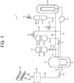
- FIG. 1 shows a nuclear power plant according to one embodiment of the present invention.
- the nuclear power plant 1 comprises a reactor vessel 10, a hybrid safety injection tank 20, a safety injection tank 25, a steam generator 30, a pressurizer 40, a coolant tank 50 and a heat-exchanger 80.
- the nuclear power plant 1 comprises cold-leg 61, hot-leg 62, various pipes 63 to 67, and various valves 71 to 76.
- the reactor vessel 10 comprises a reactor core 11, a downcomer 12, and coolant injection portions 13 and 14.
- the coolant injection portions 13 and 14 are located on the side wall of the reactor vessel 10 and communicate with the downcomer 12.
- heated pressurized coolant(coolant water) produced in the reactor vessel 10 is discharged to the high-temperature pipe 62 and then is heat-exchanged in the steam generator 30 to generate steam, and then returned to the reactor vessel 10 through the cold-leg 61.
- the pressurizer 40 is connected to the high-temperature pipe 62 via a pipe 65 and controls the system pressure during a nuclear power plant operation.
- the space within the pressurizer 40 may be divided into a lower space 41 and an upper space 42.
- the lower space 41 may contain coolant and the upper space 42 may contain steam.
- a pressure relief valve 73 is located above the pressurizer 40. When the reactor coolant system is pressurized above the operation pressure, the pressure-relief valve 73 is automatically opened to prevent damage to the coolant system. Opening the pressure relief valve 73 may allow fluid to be released to the outside such that the pressure of the coolant system is lowered.
- the high-temperature pipe 62 is connected to a pressure-reducing valve 74.
- the pressure-reducing valve 74 is opened, the pressure of the high-temperature pipe 62 is reduced.
- the hybrid safety injection tank 20 is located above the reactor vessel 10. The top of the hybrid safety injection tank 20 is connected to the cold-leg 61 through a pipe 64. The bottom of the hybrid safety injection tank 20 is connected to the coolant injection portion 13 through a pipe 63.
- the lower space 21 of the hybrid safety injection tank 20 is filled with coolant and its upper space 22 is filled with pressurizing gas.
- the pressure of the pressurizing gas in the hybrid safety injection tank 20 may be in a range of 40 to 100 atm.
- the pressurizing gas may be nitrogen gas and the coolant may contain boric acid.
- a check valve 71 is located on the pipe 63 between the hybrid safety injection tank 20 and the reactor vessel 10. The flow of coolant from the reactor vessel 10 to the hybrid safety injection tank 20 is limited by the check valve 71.
- an adjustment valve 72 is located on the pipe 64 connecting the hybrid safety injection tank 20 and the cold-leg 61.
- the regulating valve 72 remains closed during a normal operation. At this time, when the pressure of the reactor vessel 10 is lower than the pressure of the hybrid safety injection tank 20, the coolant of the hybrid safety injection tank 20 is supplied to the reactor vessel 10.
- the safety injection tank 25 is located above the reactor vessel 10. The bottom of the safety injection tank 25 is connected to the coolant injection portion 13 through a pipe 67.
- the lower space 26 of the safety injection tank 25 is filled with coolant and its upper space 27 is filled with pressurizing gas.
- the pressure of the pressurizing gas in the safety injection tank 25 may be in a range of 40 to 100 atm.
- the pressurizing gas may be nitrogen gas and the coolant may contain boric acid.
- the check valve 76 is located on the pipe 67 between the safety injection tank 25 and the reactor vessel 10. The coolant flow in the direction from the reactor vessel 10 to the safety injection tank 25 is limited by the check valve 76.
- the coolant tank 50 is at atmospheric pressure and is located higher than the reactor vessel 10.
- the coolant tank 50 is connected to the reactor vessel 10 through a pipe 66. Specifically, the coolant in the tank 50 is supplied to the downcomer 12 through the coolant injection portion 14 of the reactor vessel 10.
- a check valve 75 is provided on the pipe 66 connecting the reactor vessel 10 and the coolant tank 50 to prevent coolant flow in the direction of the coolant tank 50 from the reactor vessel 10.
- the coolant injection portions 13 and 14 connected to the hybrid safety injection tank 20 and the coolant tank 50 may be the same injection portion or individual injection portions.
- the heat-exchanger 80 is located above the reactor vessel 10 and condenses the vapor generated in the reactor building.
- the heat-exchanger 80 may be installed on the inner wall of a reactor building or may discharge the heat outside the reactor building.
- the coolant which is condensed and generated in the heat-exchanger 80, is fed to the coolant tank 50.
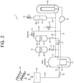
- the method first opens the regulating valve 72 as shown in FIG. 2 .
- the regulating valve 72 is opened, the cold-leg 61 and the hybrid safety injection tank 20 are communicated with each other such that the hybrid safety injection tank 20 is further pressurized.
- the cold-leg 61 and the hybrid safety injection tank 20 have the same pressure.
- the reactor vessel 10 is thus at the same pressure as that of the hybrid safety injection tank 20.
- the coolant of the hybrid safety injection tank 20 is supplied to the reactor vessel 10 due to the water head differential.
- the coolant of the hybrid safety injection tank 20 is supplied to the downcomer 12 through the coolant injection portion 13 provided on the side wall of the reactor vessel 10.
- the regulating valve 72 may be opened by manipulation of operator or by automatic operation.
- a battery may be installed and used if necessary.
- the hybrid safety injection tank 20 is connected to the cold-leg 61.
- the pressure of the hybrid safety injection tank 20 may be reduced in an emergency event by opening the pressure-relief valve 73.
- This problem does not occur when the hybrid safety injection tank 20 is connected to the cold-leg 61 in accordance with the present invention. That is, the hybrid safety injection tank 20 according to the present invention is not affected by the operation of the pressure relief valve 73 at the emergency injection timing.
- the pressure of the hybrid safety injection tank 20 may be reduced in an emergency event by opening the pressure-relief valve 73.
- the pipe 61 can supply coolant efficiently in an emergency event.
- each hybrid safety injection tank 20 is connected to an adjacent cold-leg 61, the pipe is short and simple, and the shapes of the pipes may be the same.
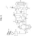
- the coolant of the coolant tank 50 is supplied to the reactor vessel 10.
- the method opens the pressure relief valve 73 and the pressure-reducing valve 74 as shown in FIG. 4 to supply the coolant of the coolant tank 50.
- the opening order of the pressure relief valve 73 and the pressure-reducing valve 74 is not limited to a specific order. In one example, and the opening operations thereof may occur simultaneously.
- the opening of the pressure relief valve 73 and the pressure-reducing valve 74 may be accomplished by manipulation of operator or by automatic operation.
- a battery may be installed and used if necessary.
- the pressure-reducing valve 74 By opening the pressure relief valve 73 and the pressure-reducing valve 74, the pressure of the pressurizer 40 and the high-temperature pipe 62 becomes close to the atmospheric pressure so that the pressure of the reactor vessel 10 becomes close to the atmospheric pressure.
- the pressure-reducing valve 74 is characterized by a larger effective releasing area than those of the pressure relief valve 73 and pressurizer connection pipe 65. Thus, the operation of the pressure-reducing valve 74 causes a rapid pressure drop in the reactor vessel 10.
- the pressure-reducing valve 74 may be installed on at least one high-temperature pipe.
- the coolant of the coolant tank 50 is supplied to the reactor vessel 10 due to the water head differential.
- the temperature of the upper portion of the reactor vessel 10 is the highest.
- the coolant is supplied through the side portion of the reactor vessel 10 to increase the reactor core cooling capacity.
- the condensed condensate is collected in the coolant tank 50.
- the heat-exchanger 80 discharges the heat inside the reactor building out of the building, thereby reducing the temperature and pressure inside the reactor building.
- the coolant may be supplied when the power (AC power) is interrupted.
Landscapes
- Physics & Mathematics (AREA)
- Engineering & Computer Science (AREA)
- Plasma & Fusion (AREA)
- General Engineering & Computer Science (AREA)
- High Energy & Nuclear Physics (AREA)
- Structure Of Emergency Protection For Nuclear Reactors (AREA)
Priority Applications (1)
| Application Number | Priority Date | Filing Date | Title |
|---|---|---|---|
| PL18735944T PL3567608T3 (pl) | 2017-01-03 | 2018-01-02 | Elektrownia jądrowa z ulepszoną wydajnością chłodzenia |
Applications Claiming Priority (3)
| Application Number | Priority Date | Filing Date | Title |
|---|---|---|---|
| KR1020170000816A KR101925704B1 (ko) | 2017-01-03 | 2017-01-03 | 발전소 정전시 피동 노심냉각 기능을 구비한 원자력 발전소 |
| KR1020170148805A KR102066325B1 (ko) | 2017-11-09 | 2017-11-09 | 냉각 성능이 개선된 원자력 발전소 및 이의 운전방법 |
| PCT/KR2018/000003 WO2018128337A2 (ko) | 2017-01-03 | 2018-01-02 | 냉각 성능이 개선된 원자력 발전소 및 이의 운전방법 |
Publications (3)
| Publication Number | Publication Date |
|---|---|
| EP3567608A2 true EP3567608A2 (de) | 2019-11-13 |
| EP3567608A4 EP3567608A4 (de) | 2020-06-10 |
| EP3567608B1 EP3567608B1 (de) | 2021-09-08 |
Family
ID=62789347
Family Applications (1)
| Application Number | Title | Priority Date | Filing Date |
|---|---|---|---|
| EP18735944.3A Active EP3567608B1 (de) | 2017-01-03 | 2018-01-02 | Kernkraftanlage mit verbesserter kühlleistung |
Country Status (4)
| Country | Link |
|---|---|
| US (1) | US20190326026A1 (de) |
| EP (1) | EP3567608B1 (de) |
| PL (1) | PL3567608T3 (de) |
| WO (1) | WO2018128337A2 (de) |
Family Cites Families (7)
| Publication number | Priority date | Publication date | Assignee | Title |
|---|---|---|---|---|
| US4753771A (en) * | 1986-02-07 | 1988-06-28 | Westinghouse Electric Corp. | Passive safety system for a pressurized water nuclear reactor |
| US5180543A (en) * | 1989-06-26 | 1993-01-19 | Westinghouse Electric Corp. | Passive safety injection system using borated water |
| US5259008A (en) * | 1992-06-24 | 1993-11-02 | Westinghouse Electric Corp. | Staged depressurization system |
| US5268943A (en) * | 1992-06-24 | 1993-12-07 | Westinghouse Electric Corp. | Nuclear reactor with makeup water assist from residual heat removal system |
| KR100563254B1 (ko) * | 2000-12-01 | 2006-03-27 | 한국과학기술원 | 냉각 장치를 이용한 가압경수로 |
| KR101100792B1 (ko) * | 2010-03-17 | 2011-12-29 | 경희대학교 산학협력단 | 원자력 발전소용 나노유체 주입장치 |
| KR101071415B1 (ko) * | 2011-04-15 | 2011-10-07 | 한국수력원자력 주식회사 | Sbo와 loca 대처 피동 고압안전주입탱크 시스템 |
-
2018
- 2018-01-02 WO PCT/KR2018/000003 patent/WO2018128337A2/ko not_active Ceased
- 2018-01-02 US US16/475,034 patent/US20190326026A1/en not_active Abandoned
- 2018-01-02 EP EP18735944.3A patent/EP3567608B1/de active Active
- 2018-01-02 PL PL18735944T patent/PL3567608T3/pl unknown
Also Published As
| Publication number | Publication date |
|---|---|
| EP3567608B1 (de) | 2021-09-08 |
| EP3567608A4 (de) | 2020-06-10 |
| WO2018128337A2 (ko) | 2018-07-12 |
| PL3567608T3 (pl) | 2022-01-24 |
| US20190326026A1 (en) | 2019-10-24 |
| WO2018128337A3 (ko) | 2018-08-30 |
Similar Documents
| Publication | Publication Date | Title |
|---|---|---|
| US9583224B2 (en) | Passive safety system of integral reactor | |
| EP0389231B1 (de) | System zur Wärmeabfuhr aus einem Behälter | |
| KR101463440B1 (ko) | 피동안전설비 및 이를 구비하는 원전 | |
| US20180350472A1 (en) | Passive safe cooling system | |
| US9761334B2 (en) | Multi stage safety injection device and passive safety injection system having the same | |
| CN109903863B (zh) | 一种安全注入系统及核电系统 | |
| US9859027B2 (en) | Multi stage safety injection device and passive safety injection system having the same | |
| US20130070887A1 (en) | Reactor adapted for mitigating loss-of-coolant accident and mitigation method thereof | |
| US11894151B2 (en) | Integrated reactor system having passive removal of residual heat | |
| US10762995B2 (en) | Shutdown cooling system and nuclear facility having same | |
| CN104766637B (zh) | 安全注入成套系统 | |
| EP4273886B1 (de) | Passives sicherheitssystem mit besonderer sicherheit und wasserversorgungssystem für ein kernkraftwerk | |
| KR101892550B1 (ko) | 중간열침원 냉각설비를 구비하는 원전 | |
| JP2024500458A (ja) | 原子炉受動的安全システム | |
| CN210837199U (zh) | 余热排出系统与核电系统 | |
| CN210956182U (zh) | 安全注入系统及核电系统 | |
| KR101463441B1 (ko) | 고농축 붕산 주입 설비 및 이를 구비하는 안전주입계통 | |
| KR101505475B1 (ko) | 피동격납부냉각계통 및 이를 구비하는 원전 | |
| JP2009058496A (ja) | 沸騰水型原子炉のハイブリッド安全系 | |
| KR101658476B1 (ko) | 원자로냉각재계통 감압 시스템 및 이를 구비하는 원전 | |
| KR101695363B1 (ko) | 피동안전계통 및 이를 구비하는 원전 | |
| KR102066325B1 (ko) | 냉각 성능이 개선된 원자력 발전소 및 이의 운전방법 | |
| US20130077730A1 (en) | Nuclear Power Plant | |
| EP3567608B1 (de) | Kernkraftanlage mit verbesserter kühlleistung | |
| EP3492811B1 (de) | Kernkraftwerke |
Legal Events
| Date | Code | Title | Description |
|---|---|---|---|
| STAA | Information on the status of an ep patent application or granted ep patent |
Free format text: STATUS: THE INTERNATIONAL PUBLICATION HAS BEEN MADE |
|
| PUAI | Public reference made under article 153(3) epc to a published international application that has entered the european phase |
Free format text: ORIGINAL CODE: 0009012 |
|
| STAA | Information on the status of an ep patent application or granted ep patent |
Free format text: STATUS: REQUEST FOR EXAMINATION WAS MADE |
|
| 17P | Request for examination filed |
Effective date: 20190724 |
|
| AK | Designated contracting states |
Kind code of ref document: A2 Designated state(s): AL AT BE BG CH CY CZ DE DK EE ES FI FR GB GR HR HU IE IS IT LI LT LU LV MC MK MT NL NO PL PT RO RS SE SI SK SM TR |
|
| AX | Request for extension of the european patent |
Extension state: BA ME |
|
| DAV | Request for validation of the european patent (deleted) | ||
| DAX | Request for extension of the european patent (deleted) | ||
| A4 | Supplementary search report drawn up and despatched |
Effective date: 20200513 |
|
| RIC1 | Information provided on ipc code assigned before grant |
Ipc: G21C 15/18 20060101AFI20200507BHEP |
|
| GRAP | Despatch of communication of intention to grant a patent |
Free format text: ORIGINAL CODE: EPIDOSNIGR1 |
|
| STAA | Information on the status of an ep patent application or granted ep patent |
Free format text: STATUS: GRANT OF PATENT IS INTENDED |
|
| INTG | Intention to grant announced |
Effective date: 20210517 |
|
| GRAS | Grant fee paid |
Free format text: ORIGINAL CODE: EPIDOSNIGR3 |
|
| GRAA | (expected) grant |
Free format text: ORIGINAL CODE: 0009210 |
|
| STAA | Information on the status of an ep patent application or granted ep patent |
Free format text: STATUS: THE PATENT HAS BEEN GRANTED |
|
| AK | Designated contracting states |
Kind code of ref document: B1 Designated state(s): AL AT BE BG CH CY CZ DE DK EE ES FI FR GB GR HR HU IE IS IT LI LT LU LV MC MK MT NL NO PL PT RO RS SE SI SK SM TR |
|
| REG | Reference to a national code |
Ref country code: GB Ref legal event code: FG4D |
|
| REG | Reference to a national code |
Ref country code: AT Ref legal event code: REF Ref document number: 1429321 Country of ref document: AT Kind code of ref document: T Effective date: 20210915 Ref country code: CH Ref legal event code: EP |
|
| REG | Reference to a national code |
Ref country code: IE Ref legal event code: FG4D |
|
| REG | Reference to a national code |
Ref country code: DE Ref legal event code: R096 Ref document number: 602018023252 Country of ref document: DE |
|
| REG | Reference to a national code |
Ref country code: FI Ref legal event code: FGE |
|
| REG | Reference to a national code |
Ref country code: LT Ref legal event code: MG9D |
|
| REG | Reference to a national code |
Ref country code: NL Ref legal event code: MP Effective date: 20210908 |
|
| PG25 | Lapsed in a contracting state [announced via postgrant information from national office to epo] |
Ref country code: NO Free format text: LAPSE BECAUSE OF FAILURE TO SUBMIT A TRANSLATION OF THE DESCRIPTION OR TO PAY THE FEE WITHIN THE PRESCRIBED TIME-LIMIT Effective date: 20211208 Ref country code: LT Free format text: LAPSE BECAUSE OF FAILURE TO SUBMIT A TRANSLATION OF THE DESCRIPTION OR TO PAY THE FEE WITHIN THE PRESCRIBED TIME-LIMIT Effective date: 20210908 Ref country code: BG Free format text: LAPSE BECAUSE OF FAILURE TO SUBMIT A TRANSLATION OF THE DESCRIPTION OR TO PAY THE FEE WITHIN THE PRESCRIBED TIME-LIMIT Effective date: 20211208 Ref country code: SE Free format text: LAPSE BECAUSE OF FAILURE TO SUBMIT A TRANSLATION OF THE DESCRIPTION OR TO PAY THE FEE WITHIN THE PRESCRIBED TIME-LIMIT Effective date: 20210908 Ref country code: RS Free format text: LAPSE BECAUSE OF FAILURE TO SUBMIT A TRANSLATION OF THE DESCRIPTION OR TO PAY THE FEE WITHIN THE PRESCRIBED TIME-LIMIT Effective date: 20210908 Ref country code: HR Free format text: LAPSE BECAUSE OF FAILURE TO SUBMIT A TRANSLATION OF THE DESCRIPTION OR TO PAY THE FEE WITHIN THE PRESCRIBED TIME-LIMIT Effective date: 20210908 Ref country code: ES Free format text: LAPSE BECAUSE OF FAILURE TO SUBMIT A TRANSLATION OF THE DESCRIPTION OR TO PAY THE FEE WITHIN THE PRESCRIBED TIME-LIMIT Effective date: 20210908 |
|
| REG | Reference to a national code |
Ref country code: AT Ref legal event code: MK05 Ref document number: 1429321 Country of ref document: AT Kind code of ref document: T Effective date: 20210908 |
|
| PG25 | Lapsed in a contracting state [announced via postgrant information from national office to epo] |
Ref country code: LV Free format text: LAPSE BECAUSE OF FAILURE TO SUBMIT A TRANSLATION OF THE DESCRIPTION OR TO PAY THE FEE WITHIN THE PRESCRIBED TIME-LIMIT Effective date: 20210908 Ref country code: GR Free format text: LAPSE BECAUSE OF FAILURE TO SUBMIT A TRANSLATION OF THE DESCRIPTION OR TO PAY THE FEE WITHIN THE PRESCRIBED TIME-LIMIT Effective date: 20211209 |
|
| PG25 | Lapsed in a contracting state [announced via postgrant information from national office to epo] |
Ref country code: AT Free format text: LAPSE BECAUSE OF FAILURE TO SUBMIT A TRANSLATION OF THE DESCRIPTION OR TO PAY THE FEE WITHIN THE PRESCRIBED TIME-LIMIT Effective date: 20210908 |
|
| PG25 | Lapsed in a contracting state [announced via postgrant information from national office to epo] |
Ref country code: IS Free format text: LAPSE BECAUSE OF FAILURE TO SUBMIT A TRANSLATION OF THE DESCRIPTION OR TO PAY THE FEE WITHIN THE PRESCRIBED TIME-LIMIT Effective date: 20220108 Ref country code: SM Free format text: LAPSE BECAUSE OF FAILURE TO SUBMIT A TRANSLATION OF THE DESCRIPTION OR TO PAY THE FEE WITHIN THE PRESCRIBED TIME-LIMIT Effective date: 20210908 Ref country code: SK Free format text: LAPSE BECAUSE OF FAILURE TO SUBMIT A TRANSLATION OF THE DESCRIPTION OR TO PAY THE FEE WITHIN THE PRESCRIBED TIME-LIMIT Effective date: 20210908 Ref country code: RO Free format text: LAPSE BECAUSE OF FAILURE TO SUBMIT A TRANSLATION OF THE DESCRIPTION OR TO PAY THE FEE WITHIN THE PRESCRIBED TIME-LIMIT Effective date: 20210908 Ref country code: PT Free format text: LAPSE BECAUSE OF FAILURE TO SUBMIT A TRANSLATION OF THE DESCRIPTION OR TO PAY THE FEE WITHIN THE PRESCRIBED TIME-LIMIT Effective date: 20220110 Ref country code: NL Free format text: LAPSE BECAUSE OF FAILURE TO SUBMIT A TRANSLATION OF THE DESCRIPTION OR TO PAY THE FEE WITHIN THE PRESCRIBED TIME-LIMIT Effective date: 20210908 Ref country code: EE Free format text: LAPSE BECAUSE OF FAILURE TO SUBMIT A TRANSLATION OF THE DESCRIPTION OR TO PAY THE FEE WITHIN THE PRESCRIBED TIME-LIMIT Effective date: 20210908 Ref country code: AL Free format text: LAPSE BECAUSE OF FAILURE TO SUBMIT A TRANSLATION OF THE DESCRIPTION OR TO PAY THE FEE WITHIN THE PRESCRIBED TIME-LIMIT Effective date: 20210908 |
|
| REG | Reference to a national code |
Ref country code: DE Ref legal event code: R097 Ref document number: 602018023252 Country of ref document: DE |
|
| PLBE | No opposition filed within time limit |
Free format text: ORIGINAL CODE: 0009261 |
|
| STAA | Information on the status of an ep patent application or granted ep patent |
Free format text: STATUS: NO OPPOSITION FILED WITHIN TIME LIMIT |
|
| PG25 | Lapsed in a contracting state [announced via postgrant information from national office to epo] |
Ref country code: DK Free format text: LAPSE BECAUSE OF FAILURE TO SUBMIT A TRANSLATION OF THE DESCRIPTION OR TO PAY THE FEE WITHIN THE PRESCRIBED TIME-LIMIT Effective date: 20210908 |
|
| REG | Reference to a national code |
Ref country code: DE Ref legal event code: R119 Ref document number: 602018023252 Country of ref document: DE |
|
| 26N | No opposition filed |
Effective date: 20220609 |
|
| PG25 | Lapsed in a contracting state [announced via postgrant information from national office to epo] |
Ref country code: SI Free format text: LAPSE BECAUSE OF FAILURE TO SUBMIT A TRANSLATION OF THE DESCRIPTION OR TO PAY THE FEE WITHIN THE PRESCRIBED TIME-LIMIT Effective date: 20210908 Ref country code: MC Free format text: LAPSE BECAUSE OF FAILURE TO SUBMIT A TRANSLATION OF THE DESCRIPTION OR TO PAY THE FEE WITHIN THE PRESCRIBED TIME-LIMIT Effective date: 20210908 |
|
| REG | Reference to a national code |
Ref country code: CH Ref legal event code: PL |
|
| REG | Reference to a national code |
Ref country code: BE Ref legal event code: MM Effective date: 20220131 |
|
| PG25 | Lapsed in a contracting state [announced via postgrant information from national office to epo] |
Ref country code: LU Free format text: LAPSE BECAUSE OF NON-PAYMENT OF DUE FEES Effective date: 20220102 Ref country code: DE Free format text: LAPSE BECAUSE OF NON-PAYMENT OF DUE FEES Effective date: 20220802 |
|
| PG25 | Lapsed in a contracting state [announced via postgrant information from national office to epo] |
Ref country code: BE Free format text: LAPSE BECAUSE OF NON-PAYMENT OF DUE FEES Effective date: 20220131 |
|
| PG25 | Lapsed in a contracting state [announced via postgrant information from national office to epo] |
Ref country code: LI Free format text: LAPSE BECAUSE OF NON-PAYMENT OF DUE FEES Effective date: 20220131 Ref country code: CH Free format text: LAPSE BECAUSE OF NON-PAYMENT OF DUE FEES Effective date: 20220131 |
|
| PG25 | Lapsed in a contracting state [announced via postgrant information from national office to epo] |
Ref country code: IT Free format text: LAPSE BECAUSE OF FAILURE TO SUBMIT A TRANSLATION OF THE DESCRIPTION OR TO PAY THE FEE WITHIN THE PRESCRIBED TIME-LIMIT Effective date: 20210908 Ref country code: IE Free format text: LAPSE BECAUSE OF NON-PAYMENT OF DUE FEES Effective date: 20220102 |
|
| PG25 | Lapsed in a contracting state [announced via postgrant information from national office to epo] |
Ref country code: MK Free format text: LAPSE BECAUSE OF FAILURE TO SUBMIT A TRANSLATION OF THE DESCRIPTION OR TO PAY THE FEE WITHIN THE PRESCRIBED TIME-LIMIT Effective date: 20210908 Ref country code: CY Free format text: LAPSE BECAUSE OF FAILURE TO SUBMIT A TRANSLATION OF THE DESCRIPTION OR TO PAY THE FEE WITHIN THE PRESCRIBED TIME-LIMIT Effective date: 20210908 |
|
| PG25 | Lapsed in a contracting state [announced via postgrant information from national office to epo] |
Ref country code: HU Free format text: LAPSE BECAUSE OF FAILURE TO SUBMIT A TRANSLATION OF THE DESCRIPTION OR TO PAY THE FEE WITHIN THE PRESCRIBED TIME-LIMIT; INVALID AB INITIO Effective date: 20180102 |
|
| PG25 | Lapsed in a contracting state [announced via postgrant information from national office to epo] |
Ref country code: TR Free format text: LAPSE BECAUSE OF FAILURE TO SUBMIT A TRANSLATION OF THE DESCRIPTION OR TO PAY THE FEE WITHIN THE PRESCRIBED TIME-LIMIT Effective date: 20210908 |
|
| PG25 | Lapsed in a contracting state [announced via postgrant information from national office to epo] |
Ref country code: MT Free format text: LAPSE BECAUSE OF FAILURE TO SUBMIT A TRANSLATION OF THE DESCRIPTION OR TO PAY THE FEE WITHIN THE PRESCRIBED TIME-LIMIT Effective date: 20210908 |
|
| PGFP | Annual fee paid to national office [announced via postgrant information from national office to epo] |
Ref country code: GB Payment date: 20251230 Year of fee payment: 9 |
|
| PGFP | Annual fee paid to national office [announced via postgrant information from national office to epo] |
Ref country code: CZ Payment date: 20251229 Year of fee payment: 9 |
|
| PGFP | Annual fee paid to national office [announced via postgrant information from national office to epo] |
Ref country code: PL Payment date: 20251229 Year of fee payment: 9 |
|
| PGFP | Annual fee paid to national office [announced via postgrant information from national office to epo] |
Ref country code: FI Payment date: 20260120 Year of fee payment: 9 |
|
| PGFP | Annual fee paid to national office [announced via postgrant information from national office to epo] |
Ref country code: FR Payment date: 20260105 Year of fee payment: 9 |