EP3567227A1 - Centrifugal debris pre-separator for turbine engine oil filter - Google Patents
Centrifugal debris pre-separator for turbine engine oil filter Download PDFInfo
- Publication number
- EP3567227A1 EP3567227A1 EP19173338.5A EP19173338A EP3567227A1 EP 3567227 A1 EP3567227 A1 EP 3567227A1 EP 19173338 A EP19173338 A EP 19173338A EP 3567227 A1 EP3567227 A1 EP 3567227A1
- Authority
- EP
- European Patent Office
- Prior art keywords
- fluid
- housing
- filter
- filtration assembly
- section
- Prior art date
- Legal status (The legal status is an assumption and is not a legal conclusion. Google has not performed a legal analysis and makes no representation as to the accuracy of the status listed.)
- Granted
Links
- 239000010705 motor oil Substances 0.000 title description 2
- 239000012530 fluid Substances 0.000 claims abstract description 122
- 238000001914 filtration Methods 0.000 claims abstract description 68
- 239000013618 particulate matter Substances 0.000 claims abstract description 45
- 239000007789 gas Substances 0.000 claims description 63
- 238000000034 method Methods 0.000 claims description 25
- 238000004891 communication Methods 0.000 claims description 16
- 230000006854 communication Effects 0.000 claims description 16
- 230000003190 augmentative effect Effects 0.000 claims description 12
- 230000007423 decrease Effects 0.000 claims description 7
- 239000000567 combustion gas Substances 0.000 claims description 4
- 239000000203 mixture Substances 0.000 claims description 4
- 238000007599 discharging Methods 0.000 claims description 3
- 230000001050 lubricating effect Effects 0.000 claims description 2
- 239000003921 oil Substances 0.000 description 75
- 238000005461 lubrication Methods 0.000 description 8
- 230000008901 benefit Effects 0.000 description 7
- 239000000446 fuel Substances 0.000 description 7
- 239000000463 material Substances 0.000 description 7
- 239000000356 contaminant Substances 0.000 description 6
- 239000002245 particle Substances 0.000 description 6
- 230000000694 effects Effects 0.000 description 5
- 230000036961 partial effect Effects 0.000 description 4
- 230000005540 biological transmission Effects 0.000 description 3
- 230000006872 improvement Effects 0.000 description 3
- 238000012423 maintenance Methods 0.000 description 3
- 230000008569 process Effects 0.000 description 3
- 230000002829 reductive effect Effects 0.000 description 3
- 239000000243 solution Substances 0.000 description 3
- JKIYPXKCQBHOLY-UHFFFAOYSA-N 5-(dimethylamino)-2-(1,3-thiazol-2-yldiazenyl)benzoic acid Chemical compound OC(=O)C1=CC(N(C)C)=CC=C1N=NC1=NC=CS1 JKIYPXKCQBHOLY-UHFFFAOYSA-N 0.000 description 2
- 230000009471 action Effects 0.000 description 2
- 230000003247 decreasing effect Effects 0.000 description 2
- 230000003116 impacting effect Effects 0.000 description 2
- 238000002347 injection Methods 0.000 description 2
- 239000007924 injection Substances 0.000 description 2
- 239000002923 metal particle Substances 0.000 description 2
- 230000003134 recirculating effect Effects 0.000 description 2
- 230000009467 reduction Effects 0.000 description 2
- 238000000926 separation method Methods 0.000 description 2
- OKTJSMMVPCPJKN-UHFFFAOYSA-N Carbon Chemical compound [C] OKTJSMMVPCPJKN-UHFFFAOYSA-N 0.000 description 1
- 230000001133 acceleration Effects 0.000 description 1
- 230000006978 adaptation Effects 0.000 description 1
- 239000000853 adhesive Substances 0.000 description 1
- 230000001070 adhesive effect Effects 0.000 description 1
- 238000009529 body temperature measurement Methods 0.000 description 1
- 229910052799 carbon Inorganic materials 0.000 description 1
- 230000008859 change Effects 0.000 description 1
- 238000002485 combustion reaction Methods 0.000 description 1
- 230000006835 compression Effects 0.000 description 1
- 238000007906 compression Methods 0.000 description 1
- 238000010276 construction Methods 0.000 description 1
- 238000011109 contamination Methods 0.000 description 1
- 239000002826 coolant Substances 0.000 description 1
- 238000012937 correction Methods 0.000 description 1
- 230000008878 coupling Effects 0.000 description 1
- 238000010168 coupling process Methods 0.000 description 1
- 238000005859 coupling reaction Methods 0.000 description 1
- 230000000593 degrading effect Effects 0.000 description 1
- 238000013461 design Methods 0.000 description 1
- 238000001514 detection method Methods 0.000 description 1
- 239000006249 magnetic particle Substances 0.000 description 1
- 230000007246 mechanism Effects 0.000 description 1
- 230000003449 preventive effect Effects 0.000 description 1
- 230000004044 response Effects 0.000 description 1
- 230000000717 retained effect Effects 0.000 description 1
- 239000013049 sediment Substances 0.000 description 1
- 230000003068 static effect Effects 0.000 description 1
- 238000013024 troubleshooting Methods 0.000 description 1
- 238000011144 upstream manufacturing Methods 0.000 description 1
Images


Classifications
-
- F—MECHANICAL ENGINEERING; LIGHTING; HEATING; WEAPONS; BLASTING
- F01—MACHINES OR ENGINES IN GENERAL; ENGINE PLANTS IN GENERAL; STEAM ENGINES
- F01M—LUBRICATING OF MACHINES OR ENGINES IN GENERAL; LUBRICATING INTERNAL COMBUSTION ENGINES; CRANKCASE VENTILATING
- F01M1/00—Pressure lubrication
- F01M1/10—Lubricating systems characterised by the provision therein of lubricant venting or purifying means, e.g. of filters
-
- F—MECHANICAL ENGINEERING; LIGHTING; HEATING; WEAPONS; BLASTING
- F01—MACHINES OR ENGINES IN GENERAL; ENGINE PLANTS IN GENERAL; STEAM ENGINES
- F01M—LUBRICATING OF MACHINES OR ENGINES IN GENERAL; LUBRICATING INTERNAL COMBUSTION ENGINES; CRANKCASE VENTILATING
- F01M11/00—Component parts, details or accessories, not provided for in, or of interest apart from, groups F01M1/00 - F01M9/00
- F01M11/03—Mounting or connecting of lubricant purifying means relative to the machine or engine; Details of lubricant purifying means
-
- B—PERFORMING OPERATIONS; TRANSPORTING
- B01—PHYSICAL OR CHEMICAL PROCESSES OR APPARATUS IN GENERAL
- B01D—SEPARATION
- B01D21/00—Separation of suspended solid particles from liquids by sedimentation
- B01D21/26—Separation of sediment aided by centrifugal force or centripetal force
- B01D21/265—Separation of sediment aided by centrifugal force or centripetal force by using a vortex inducer or vortex guide, e.g. coil
-
- B—PERFORMING OPERATIONS; TRANSPORTING
- B01—PHYSICAL OR CHEMICAL PROCESSES OR APPARATUS IN GENERAL
- B01D—SEPARATION
- B01D29/00—Filters with filtering elements stationary during filtration, e.g. pressure or suction filters, not covered by groups B01D24/00 - B01D27/00; Filtering elements therefor
- B01D29/11—Filters with filtering elements stationary during filtration, e.g. pressure or suction filters, not covered by groups B01D24/00 - B01D27/00; Filtering elements therefor with bag, cage, hose, tube, sleeve or like filtering elements
- B01D29/13—Supported filter elements
- B01D29/15—Supported filter elements arranged for inward flow filtration
- B01D29/21—Supported filter elements arranged for inward flow filtration with corrugated, folded or wound sheets
-
- B—PERFORMING OPERATIONS; TRANSPORTING
- B01—PHYSICAL OR CHEMICAL PROCESSES OR APPARATUS IN GENERAL
- B01D—SEPARATION
- B01D29/00—Filters with filtering elements stationary during filtration, e.g. pressure or suction filters, not covered by groups B01D24/00 - B01D27/00; Filtering elements therefor
- B01D29/11—Filters with filtering elements stationary during filtration, e.g. pressure or suction filters, not covered by groups B01D24/00 - B01D27/00; Filtering elements therefor with bag, cage, hose, tube, sleeve or like filtering elements
- B01D29/31—Self-supporting filtering elements
- B01D29/33—Self-supporting filtering elements arranged for inward flow filtration
-
- B—PERFORMING OPERATIONS; TRANSPORTING
- B01—PHYSICAL OR CHEMICAL PROCESSES OR APPARATUS IN GENERAL
- B01D—SEPARATION
- B01D29/00—Filters with filtering elements stationary during filtration, e.g. pressure or suction filters, not covered by groups B01D24/00 - B01D27/00; Filtering elements therefor
- B01D29/50—Filters with filtering elements stationary during filtration, e.g. pressure or suction filters, not covered by groups B01D24/00 - B01D27/00; Filtering elements therefor with multiple filtering elements, characterised by their mutual disposition
- B01D29/56—Filters with filtering elements stationary during filtration, e.g. pressure or suction filters, not covered by groups B01D24/00 - B01D27/00; Filtering elements therefor with multiple filtering elements, characterised by their mutual disposition in series connection
- B01D29/58—Filters with filtering elements stationary during filtration, e.g. pressure or suction filters, not covered by groups B01D24/00 - B01D27/00; Filtering elements therefor with multiple filtering elements, characterised by their mutual disposition in series connection arranged concentrically or coaxially
-
- F—MECHANICAL ENGINEERING; LIGHTING; HEATING; WEAPONS; BLASTING
- F02—COMBUSTION ENGINES; HOT-GAS OR COMBUSTION-PRODUCT ENGINE PLANTS
- F02C—GAS-TURBINE PLANTS; AIR INTAKES FOR JET-PROPULSION PLANTS; CONTROLLING FUEL SUPPLY IN AIR-BREATHING JET-PROPULSION PLANTS
- F02C7/00—Features, components parts, details or accessories, not provided for in, or of interest apart form groups F02C1/00 - F02C6/00; Air intakes for jet-propulsion plants
- F02C7/06—Arrangements of bearings; Lubricating
-
- F—MECHANICAL ENGINEERING; LIGHTING; HEATING; WEAPONS; BLASTING
- F16—ENGINEERING ELEMENTS AND UNITS; GENERAL MEASURES FOR PRODUCING AND MAINTAINING EFFECTIVE FUNCTIONING OF MACHINES OR INSTALLATIONS; THERMAL INSULATION IN GENERAL
- F16N—LUBRICATING
- F16N39/00—Arrangements for conditioning of lubricants in the lubricating system
- F16N39/06—Arrangements for conditioning of lubricants in the lubricating system by filtration
-
- B—PERFORMING OPERATIONS; TRANSPORTING
- B01—PHYSICAL OR CHEMICAL PROCESSES OR APPARATUS IN GENERAL
- B01D—SEPARATION
- B01D2201/00—Details relating to filtering apparatus
- B01D2201/32—Flow characteristics of the filter
-
- F—MECHANICAL ENGINEERING; LIGHTING; HEATING; WEAPONS; BLASTING
- F01—MACHINES OR ENGINES IN GENERAL; ENGINE PLANTS IN GENERAL; STEAM ENGINES
- F01D—NON-POSITIVE DISPLACEMENT MACHINES OR ENGINES, e.g. STEAM TURBINES
- F01D25/00—Component parts, details, or accessories, not provided for in, or of interest apart from, other groups
- F01D25/18—Lubricating arrangements
-
- F—MECHANICAL ENGINEERING; LIGHTING; HEATING; WEAPONS; BLASTING
- F01—MACHINES OR ENGINES IN GENERAL; ENGINE PLANTS IN GENERAL; STEAM ENGINES
- F01M—LUBRICATING OF MACHINES OR ENGINES IN GENERAL; LUBRICATING INTERNAL COMBUSTION ENGINES; CRANKCASE VENTILATING
- F01M1/00—Pressure lubrication
- F01M1/10—Lubricating systems characterised by the provision therein of lubricant venting or purifying means, e.g. of filters
- F01M2001/1007—Lubricating systems characterised by the provision therein of lubricant venting or purifying means, e.g. of filters characterised by the purification means combined with other functions
-
- F—MECHANICAL ENGINEERING; LIGHTING; HEATING; WEAPONS; BLASTING
- F01—MACHINES OR ENGINES IN GENERAL; ENGINE PLANTS IN GENERAL; STEAM ENGINES
- F01M—LUBRICATING OF MACHINES OR ENGINES IN GENERAL; LUBRICATING INTERNAL COMBUSTION ENGINES; CRANKCASE VENTILATING
- F01M1/00—Pressure lubrication
- F01M1/10—Lubricating systems characterised by the provision therein of lubricant venting or purifying means, e.g. of filters
- F01M2001/1028—Lubricating systems characterised by the provision therein of lubricant venting or purifying means, e.g. of filters characterised by the type of purification
- F01M2001/1035—Lubricating systems characterised by the provision therein of lubricant venting or purifying means, e.g. of filters characterised by the type of purification comprising centrifugal filters
-
- F—MECHANICAL ENGINEERING; LIGHTING; HEATING; WEAPONS; BLASTING
- F01—MACHINES OR ENGINES IN GENERAL; ENGINE PLANTS IN GENERAL; STEAM ENGINES
- F01M—LUBRICATING OF MACHINES OR ENGINES IN GENERAL; LUBRICATING INTERNAL COMBUSTION ENGINES; CRANKCASE VENTILATING
- F01M1/00—Pressure lubrication
- F01M1/10—Lubricating systems characterised by the provision therein of lubricant venting or purifying means, e.g. of filters
- F01M2001/105—Lubricating systems characterised by the provision therein of lubricant venting or purifying means, e.g. of filters characterised by the layout of the purification arrangements
- F01M2001/1057—Lubricating systems characterised by the provision therein of lubricant venting or purifying means, e.g. of filters characterised by the layout of the purification arrangements comprising a plurality of filters, parallel or serial
-
- F—MECHANICAL ENGINEERING; LIGHTING; HEATING; WEAPONS; BLASTING
- F02—COMBUSTION ENGINES; HOT-GAS OR COMBUSTION-PRODUCT ENGINE PLANTS
- F02C—GAS-TURBINE PLANTS; AIR INTAKES FOR JET-PROPULSION PLANTS; CONTROLLING FUEL SUPPLY IN AIR-BREATHING JET-PROPULSION PLANTS
- F02C3/00—Gas-turbine plants characterised by the use of combustion products as the working fluid
- F02C3/04—Gas-turbine plants characterised by the use of combustion products as the working fluid having a turbine driving a compressor
-
- F—MECHANICAL ENGINEERING; LIGHTING; HEATING; WEAPONS; BLASTING
- F05—INDEXING SCHEMES RELATING TO ENGINES OR PUMPS IN VARIOUS SUBCLASSES OF CLASSES F01-F04
- F05D—INDEXING SCHEME FOR ASPECTS RELATING TO NON-POSITIVE-DISPLACEMENT MACHINES OR ENGINES, GAS-TURBINES OR JET-PROPULSION PLANTS
- F05D2220/00—Application
- F05D2220/30—Application in turbines
- F05D2220/32—Application in turbines in gas turbines
- F05D2220/323—Application in turbines in gas turbines for aircraft propulsion, e.g. jet engines
-
- F—MECHANICAL ENGINEERING; LIGHTING; HEATING; WEAPONS; BLASTING
- F05—INDEXING SCHEMES RELATING TO ENGINES OR PUMPS IN VARIOUS SUBCLASSES OF CLASSES F01-F04
- F05D—INDEXING SCHEME FOR ASPECTS RELATING TO NON-POSITIVE-DISPLACEMENT MACHINES OR ENGINES, GAS-TURBINES OR JET-PROPULSION PLANTS
- F05D2260/00—Function
- F05D2260/60—Fluid transfer
- F05D2260/607—Preventing clogging or obstruction of flow paths by dirt, dust, or foreign particles
-
- F—MECHANICAL ENGINEERING; LIGHTING; HEATING; WEAPONS; BLASTING
- F05—INDEXING SCHEMES RELATING TO ENGINES OR PUMPS IN VARIOUS SUBCLASSES OF CLASSES F01-F04
- F05D—INDEXING SCHEME FOR ASPECTS RELATING TO NON-POSITIVE-DISPLACEMENT MACHINES OR ENGINES, GAS-TURBINES OR JET-PROPULSION PLANTS
- F05D2260/00—Function
- F05D2260/98—Lubrication
-
- F—MECHANICAL ENGINEERING; LIGHTING; HEATING; WEAPONS; BLASTING
- F16—ENGINEERING ELEMENTS AND UNITS; GENERAL MEASURES FOR PRODUCING AND MAINTAINING EFFECTIVE FUNCTIONING OF MACHINES OR INSTALLATIONS; THERMAL INSULATION IN GENERAL
- F16N—LUBRICATING
- F16N2210/00—Applications
- F16N2210/02—Turbines
-
- F—MECHANICAL ENGINEERING; LIGHTING; HEATING; WEAPONS; BLASTING
- F16—ENGINEERING ELEMENTS AND UNITS; GENERAL MEASURES FOR PRODUCING AND MAINTAINING EFFECTIVE FUNCTIONING OF MACHINES OR INSTALLATIONS; THERMAL INSULATION IN GENERAL
- F16N—LUBRICATING
- F16N2210/00—Applications
- F16N2210/08—Aircraft
-
- Y—GENERAL TAGGING OF NEW TECHNOLOGICAL DEVELOPMENTS; GENERAL TAGGING OF CROSS-SECTIONAL TECHNOLOGIES SPANNING OVER SEVERAL SECTIONS OF THE IPC; TECHNICAL SUBJECTS COVERED BY FORMER USPC CROSS-REFERENCE ART COLLECTIONS [XRACs] AND DIGESTS
- Y02—TECHNOLOGIES OR APPLICATIONS FOR MITIGATION OR ADAPTATION AGAINST CLIMATE CHANGE
- Y02T—CLIMATE CHANGE MITIGATION TECHNOLOGIES RELATED TO TRANSPORTATION
- Y02T50/00—Aeronautics or air transport
- Y02T50/60—Efficient propulsion technologies, e.g. for aircraft
Definitions
- This disclosure relates to fluid filtration, such as suitable for use in engine oil filtration of an aircraft engine.
- filtering systems including, for example, engine filtration systems that are configured to remove physical contaminants from fluids, such as engine coolants, oil, fuel, hydraulic fluids, transmission fluids, etc.
- fluids such as engine coolants, oil, fuel, hydraulic fluids, transmission fluids, etc.
- filter mechanisms find utility in various applications.
- Oil is circulated through the engine and can carry physical contaminants, such as carbon particles, metal particles, dirt, etc., which can harm an engine if not removed from an engine's lubrication system. Accordingly, oil is oftentimes passed through an oil filtration assembly comprising one or more filters in order to remove contaminants from the oil before the oil is recirculated back into the engine.
- a fluid filtration assembly includes a housing having a thickness defined between an internal surface of the housing and an external surface of the housing, the housing configured to receive a first filter and define an outer annular flow passage between a first outer surface of the first filter and the internal surface of the housing; an inlet pipe in fluid communication with the fluid filtration assembly, the inlet pipe configured to inject a fluid into the housing to impart a centrifugal force; an outlet pipe in fluid communication with the fluid filtration assembly to discharge the fluid from the housing; and a collection area disposed towards an end of the outer annular flow passage distal the inlet pipe, the collection area configured to collect particulate matter from the fluid; wherein a width of the outer annular flow passage increases towards the collection area.
- the thickness of the housing decreases towards the collection area; and/or an outer diameter of the housing increases towards the collection area; and/or the width of the outer annular flow passage increases towards the collection area to augment the centrifugal force; and/or the fluid filtration assembly is an oil filtration assembly and the fluid is an oil; and/or the fluid filtration assembly further includes a drain plug proximate an end cap near the collection area; and/or the fluid filtration assembly further includes a turning vane assembly proximate the inlet pipe; and/or the fluid filtration assembly further includes a second filter configured within the first filter.
- a gas turbine engine includes a fan section configured to induce air from a surrounding environment into the gas turbine engine; a compressor section in fluid communication with the fan section and configured to compress the air received from the fan section; a combustor section in fluid communication with the compressor section and configured to ignite a fuel-air mixture to generate combustion gases; a turbine section in fluid communication with the combustor section; and a debris capture device to remove particulate matter from fluids associated with lubricating rotating components of the gas turbine engine, including a housing having a thickness defined between an internal surface of the housing and an external surface of the housing, the housing configured to receive a first filter and define an outer annular flow passage between a first outer surface of the first filter and the internal surface of the housing; an inlet pipe in fluid communication with the oil filtration assembly, the inlet pipe configured to inject an oil into the housing to impart a centrifugal force; an outlet pipe in fluid communication with the oil filtration assembly to discharge the oil from the housing; and a collection area disposed towards an end of the outer annul
- the thickness of the housing decreases towards the collection area; and/or an outer diameter of the housing increases towards the collection area; and/or the width of the outer annular flow passage increases towards the collection area to augment the centrifugal force; and/or the gas turbine engine further includes a drain plug proximate an end cap near the collection area; and/or the gas turbine engine further includes a turning vane assembly proximate the inlet pipe; and/or the gas turbine engine further includes a second filter configured within the first filter.
- a method of filtering particulate matter from a fluid filtration assembly includes injecting a fluid into a housing with a centrifugal force; augmenting the centrifugal force within the housing by increasing a width of an outer annular flow passage between a first outer surface of a filter and an internal surface of the housing; an collecting particulate matter from the fluid in a collection area due to the augmented centrifugal force before the particulate matter impacts the filter.
- the method further includes discharging the fluid from the housing; and/or the fluid filtration assembly is an oil filtration assembly and the fluid is an oil; and/or the fluid filtration assembly is a component of a gas turbine engine; and/or the method further includes additionally augmenting the centrifugal force by imparting an additional rotational force to the fluid as the fluid enters the housing.
- systems and methods are described for pre-separating particulate matter before it passes through one or more filters within a fluid filtration system, such as an oil filtration system.
- a fluid filtration system such as an oil filtration system.
- the systems and methods enable less particulate matter to impact filter(s) within filtration systems.
- a representative gas turbine engine 10 is a multi-spool turbofan having rotating components and incorporating a fan section 12, a compressor section 14, a combustor section 16, and a turbine section 18.
- the gas turbine engine 10 includes other systems and features too.
- the fan section 12 is positioned towards a front or inlet of the gas turbine engine 10, and it includes a fan 20 that induces air from a surrounding environment into the gas turbine engine 10 and accelerates a portion of the air towards the compressor section 14.
- the fan section 12 drives the air along a bypass flowpath B while the compressor section 14 drives the air along a core flowpath C for acceleration, communication, and compression into the combustor section 16, then expansion within the turbine section 18.
- the compressor section 14 raises the pressure of the air received from the fan section 12 to a relatively high level.
- the compressed air from the compressor section 14 then enters the combustor section 16, where one or more fuel nozzles inject fuel into the compressed air.
- the fuel-air mixture is ignited in the combustor section 16 to generate combustion gases.
- the high-energy combustion gases from the combustor section 16 then flow into and through the turbine section 18, thereby causing rotationally mounted turbine blades to rotate and generate energy.
- the air exiting the turbine section 18 is exhausted from the gas turbine engine 10 via an exhaust section.
- the gas turbine engine 10 includes one or more of a low pressure compressor (LPC) 22, a high pressure compressor (HPC) 24, a high pressure turbine (HPT) 26, and/or a low pressure turbine (LPT) 28.
- LPC low pressure compressor
- HPC high pressure compressor
- HPT high pressure turbine
- LPT low pressure turbine
- the gas turbine engine 10 is or includes other types of engines, such as turbojets, turboshafts, three-spool (plus fan) turbofans, and/or direct drive turbofans.
- an intermediate spool includes an intermediate pressure compressor (not shown) between the LPC 22 and the HPC 24 and/or an intermediate pressure turbine (not shown) between the HPT 26 and the LPT 28.
- the gas turbine engine 10 includes a low spool 30 and a high spool 32 mounted for rotation about an engine central longitudinal axis A - A' relative to an engine static structure or engine case 34 via multiple bearing structures.
- the low spool 30 includes an inner shaft 36 that interconnects the fan 20 of the fan section 12, the LPC 22 of the compressor section 14, and the LPT 28 of the turbine section 18.
- the inner shaft 36 communicates with the fan 20 directly or through a geared architecture 38 to drive the low spool 30 at a higher speed than the fan 20.
- a reduction transmission is an epicyclic transmission, such as a planetary or star gear system.
- the high spool 32 includes an outer shaft 40 that interconnects the HPC 24 of the compressor section 14 and the HPT 26 of the turbine section 18.
- a combustor 42 is arranged between the HPC 24 and the HPT 26.
- the inner shaft 36 and the outer shaft 40 are concentric and rotate about the engine central longitudinal axis A - A' that is collinear with their longitudinal axes. Core airflow flowing along core flowpath C is compressed by the LPC 22, further compressed by the HPC 24, mixed with fuel, burned in the combustor 42, and then expanded over the HPT 26 and the LPT 28.
- the HPT 26 and the LPT 28 rotationally communicate with the high spool 32 and the low spool 30, respectively, in response to the expansion.
- the gas turbine engine 10 is a high-bypass geared aircraft engine. In various embodiments, the gas turbine engine 10 bypass ratio is greater than approximately 6:1.
- the geared architecture 38 includes an epicyclic gear train, such as a planetary gear system or other gear system. In various embodiments, the example epicyclic gear train has a gear reduction ratio of greater than approximately 2.3:1, and, in other embodiments, it is greater than approximately 2.5:1.
- the geared turbofan enables operation of the low spool 30 at higher speeds that can increase the operational efficiency of the LPC 22 and the LPT 28 and render increased pressure in fewer numbers of stages.
- a pressure ratio associated with the LPT 28 is pressure-measured prior to the inlet of the LPT 28 as related to the pressure at the outlet of the LPT 28 prior to an exhaust nozzle of the gas turbine engine 10.
- the bypass ratio of the gas turbine engine 10 is greater than approximately 10:1
- the fan 20 diameter is significantly larger than that of the LPC 22, and the LPT 28 has a pressure ratio that is greater than approximately 5:1.
- a significant amount of thrust is provided by the bypass flowpath B due to the high bypass ratio.
- the fan section 12 is suited for a particular flight condition-e.g., cruising at approximately 0.8 Mach and/or approximately 35,000 feet (10,668 meters). This flight condition, with the gas turbine engine 10 at a preferred fuel consumption, is known as thrust specific fuel consumption (TSFC), which is an industry-standard parameter of fuel consumption per unit of thrust.
- TSFC thrust specific fuel consumption
- Fan pressure ratio is a pressure ratio across a blade of the fan 20 in the fan section 12 without using a fan exit guide vane system.
- a low fan pressure ratio of the gas turbine engine 10 is less than 1.45.
- a low corrected fan tip speed is the actual fan tip speed divided by an industry-standard temperature correction of (TAMB/518.7)(0.5), in which TAMB is an ambient temperature measurement in degrees Rankine.
- the low corrected fan tip speed of the gas turbine engine 10 is less than approximately 1,150 feet (351 meters) per second.
- the gas turbine engine 10 also includes a first debris capture device (DCD) 44, a second debris capture device (DCD) 46, and/or an oil debris monitor (ODM) 48, each configured for operation with a lubrication oil system of the gas turbine engine 10.
- DCD debris capture device
- DCD second debris capture device
- ODM oil debris monitor
- the first DCD 44, the second DCD 46, and/or the ODM 48 are associated with and/or proximate to an accessory gearbox 50 that is proximate the compressor section 14, with the first DCD 44 being located at a first location A proximate the accessory gearbox 50, the second DCD 46 being located at a second location B proximate the accessory gearbox 50, and the ODM 48 being located at a third location C proximate the accessory gearbox 50 (e.g., see FIG. 2 ).
- Such an arrangement/placement is referred to as a core mount, with the first DCD 44, the second DCD 46, and/or the ODM 48 being located generally proximate the compressor section 14.
- the first DCD 44, the second DCD 46, and/or the ODM 48 are also located generally proximate the fan section 12, and such an arrangement/placement is referred to as a fan mount, as well as in other locations throughout the gas turbine engine 10 as well, for example.
- oil flows into and/or out of one or more of the first DCD 44, the second DCD 46, and/or the ODM 48.
- the first DCD 44, the second DCD 46, and/or the ODM 48 are located at various locations within the lubrication oil system of the gas turbine engine 10, thereby assisting in localizing the source of particulate matter (e.g., contaminants, debris, dirt, flecks of material, sediment, etc.) within the gas turbine engine 10.
- the first DCD 44 and/or the second DCD 46 are located downstream within the lubrication oil system of particular components that are subject to particular wear within the gas turbine engine 10, whereby the detection of particulate matter within a particular DCD indicates a particular component within a particular part of the gas turbine engine 10 is, or may be, degrading.
- an initial DCD to detect debris can be assumed to be a closest DCD downstream of a particular component that is providing debris to the lubrication oil system of the gas turbine engine 10.
- components upstream of that component are considered suspect, in various embodiments.
- secondary indications e.g., temperature variations, vibrations, etc. are also used to identify suspect components.
- information from the first DCD 44, the second DCD 46, and/or the ODM 48 is analyzed to determine whether or not the gas turbine engine 10 is operating within predetermined limits.
- the first DCD 44 includes a filtration assembly, such as an oil filtration assembly (OFA) 52, that is configured to detect and extract magnetic and/or nonmagnetic particles that are carried by the lubrication oil of the gas turbine engine 10
- the second DCD 46 includes a chip detector 54 that is configured to detect and extract magnetic particles that are carried by the lubrication oil of the gas turbine engine 10.
- the ODM 48 includes an inductor coil 56 that is configured to enable the ODM 48 to determine one or more of a debris particle's composition, count, mass, size, etc. In various embodiments, these particle characteristics are analyzed at single points in time, cumulatively over time, and/or as rates of change over time, for example.
- the OFA 52 includes a housing 58 having a first section 60 and conjoined second section 62 distal from the first section 60.
- a length of the first section 60 and a length of the second section 62 sum to an overall length OL of the housing 58.
- the OFA 52 is generally oriented vertically, with the first section 60 disposed above the second section 62.
- any and all position orientations referenced or implied herein are used as arbitrary reference positions only, based on a convenience of describing the components in the figures; they do not necessarily or preferably refer to the positions of elements with respect to a gravitation pull of the Earth, nor to any other extrinsic and/or intrinsic reference forces to which the OFA 52 is, or maybe, subjected.
- Fluid flow enters the OFA 52 through an inlet pipe 64 that is disposed proximate to, and/or within, the first section 60 and exits the OFA 52 through an outlet pipe 66 that is also disposed proximate to, and/or within, the first section 60.
- the inlet pipe 64 and the outlet pipe 66 are fluidly connected internally within the housing 58.
- a fluid e.g., oil
- a fluid e.g., oil
- This tangential (or substantially tangential) injection imparts a rotational flow (e.g., spin) to the fluid (e.g., oil) relative to a centerline CL as it enters the first section 60.
- a rotational flow e.g., spin
- an angled orientation (e.g., tangential or substantially tangential) of the inlet pipe 64 relative to the centerline CL of the OFA 52 creates a cyclonic effect for the fluid (e.g., oil) as it enters the first section 60 of the OFA 52 and travels through the first section 60 and into the second section 62. After the fluid enters the first section 60, at least part of the fluid cyclonically travels down the OFA 52 and into the second section 62, which is a continuation of the first section 60 of the housing 58.
- the fluid e.g., oil
- an end cap 68 forces fluid (e.g., oil) back up the OFA 52 towards the first section 60 through a center cavity 70 en-route to the outlet pipe 66, which is in fluid communication with the first section 60 and the second section 62 throughout the overall length OL of the housing 58 and discharges the fluid (e.g., oil) from the OFA 52.
- fluid e.g., oil
- a first (or primary) filter 72 and/or a second (or secondary) filter 74 is/are disposed within the housing 58, each running substantially the length of the first section 60 and the second section 62 (e.g., the overall length OL) of the housing 58 towards the end cap 68.
- the end cap 68 terminates at or about an outer radial limit of the first filter 72, thereby generally defining a bottom surface to seat the first filter 72 and/or the second filter 74 within the housing 58.
- the end cap 68, the first filter 72, and/or the second filter 74 are bound together, such as with an adhesive or the like.
- the first filter 72 and/or the second filter 74 are primarily annular structures, aligned substantially coaxially and symmetrically along the centerline CL of the OFA 52-e.g., in a nested and/or multi-stage relationship with one another, in various embodiments.
- the first filter 72 comprises a filter media FM with porous passages disposed between a first outer surface 76 and a first inner surface 78.
- the first filter 72 is a substantially cylindrical outside-in filter, configured such that the first outer surface 76 is, effectively, a filter inlet, and the first inner surface 78 is, effectively, a filter outlet.
- the fluid e.g., oil
- the first filter 72 has multiple outer surfaces and multiple inner surfaces (e.g., see FIG. 5-A and FIG.
- first outer surface 76 of the first filter 72 generally refers to a part or portion of the first filter 72 that extends radially furthest from the first filter 72 in relation to the centerline CL
- first inner surface 78 of the first filter 72 generally refers to a part or portion of the first filter 72 that extends radially closest from the first filter 72 in relation to the centerline CL.
- the second filter 74 also comprises a filter media FM with porous passages disposed between a second outer surface 80 and a second inner surface 82.
- the second filter 74 is also a substantially cylindrical outside-in filter, configured such that the second outer surface 80 is, effectively, a filter inlet, and the second inner surface 82 is, effectively, a filter outlet.
- the fluid e.g., oil
- the second filter 74 has multiple outer surfaces and multiple inner surfaces (e.g., see FIG. 5-A and FIG.
- the second inner surface 82 of the second filter 74 defines the center cavity 70, and the center cavity 70 forms a hollow core passage directed towards the outlet pipe 66.
- the center cavity 70 runs the overall length OL, or substantially the overall length OL, of the housing 58. In various embodiments, the center cavity 70 is shorter than the overall length OL of the housing 58. In various embodiments, the center cavity 70 is longer than the overall length OL of the housing 58.
- the housing 58 is generally defined by an internal surface 84 and an external surface 86, comprising a thickness T between the internal surface 84 and the external surface 86.
- the thickness T is generally defined throughout the overall length OL of the housing 58, and the thickness T may be the same or different between the first section 60 and the second section 62, including generally varying over the overall length OL of the housing 58.
- the first outer surface 76 of the first filter 72 is positioned, spaced, and/or sized internally apart from the internal surface 84 of the housing 58 to form an outer annular flow passage 88 between the first outer surface 76 of the first filter 72 and the internal surface 84 of the housing 58.
- the outer annular flow passage 88 extends further than the end cap 68 at the distal end of the second section 62 of the housing 58.
- the first inner surface 78 of the first filter 72 is positioned, spaced, and/or sized internally apart from the second outer surface 80 of the second filter 74 to form an inner annular flow passage 90 between the first inner surface 78 of the first filter 72 and the second outer surface 80 of the second filter 74.
- fluid e.g., oil
- fluid from the gas turbine engine 10 tangentially enters the OFA 52 at the inlet pipe 64 and flows in and though the outer annular flow passage 88, the first filter 72, the inner annular flow passage 90, the second filter 74, the center cavity 70, and/or the outlet pipe 66 of the OFA 52, before returning and/or being returned to the gas turbine engine 10 of FIG. 1 .
- the first filter 72 and/or the second filter 74 are formed with pleated materials as the filter media, such as shown, for example, in FIG. 5-A and 5-B .
- the filter media FM of the first filter 72 and/or the filter media FM of the second filter 74 is/are configured to remove particulate contaminants from the oil as the oil passes through the filter media FM of the first filter 72 and/or the second filter 74. In various embodiments, the filter media FM of the first filter 72 and/or the filter media FM of the second filter 74 is/are configured to remove particulate contaminants from the oil before the oil is recirculated back to gas turbine engine 10 of FIG. 1 through the outlet pipe 66.
- the filter media FM of the first filter 72 and the filter media FM of the second filter 74 are made of the substantially the same materials. In various embodiments, the filter media FM of the first filter 72 and the filter media FM of the second filter 74 are made of the substantially different materials. In various embodiments, they are configured with the same or different grades and/or levels of filtration capacities (e.g., mesh layers), as well as different lengths and/or radial sizes.
- the OFA 52 includes one or more filters within the housing 58, such as the first filter 72 and/or the second filter 74. In various embodiments, the OFA 52 includes the first filter 72 and not the second filter 74. In various embodiments, the OFA 52 includes the second filter 74 and not the first filter 72. In various embodiments, the OFA 52 includes both the first filter 72 and the second filter 74. In various embodiments, the OFA 52 includes other filters too.
- the first filter 72 and/or the second filter 74 prevent and/or lessen particulate matter from recirculating to the gas turbine engine 10.
- the more particulate matter that the first filter 72 and/or the second filter 74 extract from the fluid e.g., oil
- the fluid e.g., oil
- the more particulate matter that the first filter 72 and/or the second filter 74 extract from the fluid e.g., oil
- the more often the first filter 72 and/or the second filter 74 will need to be changed, cleaned, and/or replaced the more often the first filter 72 and/or the second filter 74 will need to be changed, cleaned, and/or replaced.
- the less particulate matter that the first filter 72 and/or the second filter 74 extract from the fluid e.g., oil
- the less often the first filter 72 and/or the second filter 74 will need to be changed, cleaned, and/or replaced e.g., oil
- the less particulate matter that impacts the first filter 72 and/or the second filter 74 improves working lives of the first filter 72 and/or the second filter 74, provided sufficient particulate matter can be and/or is extracted from the fluid (e.g., oil) to still be able to protect the gas turbine engine 10 as the fluid (e.g., oil) is recirculated from the OFA 52 back through the outlet pipe 66 and to the gas turbine engine 10.
- the fluid e.g., oil
- particulate matter is extracted from the fluid (e.g., oil) before it impacts the first filter 72 and/or the second filter 74, then the first filter 72 and/or the second filter 74 will have less particulate matter to extract, in various embodiments.
- the fluid e.g., oil
- a centrifugal action imparted by the tangential inlet pipe 64 decreases the amount of particulate matter impacting the first filter 72. More specifically, as the fluid (e.g., oil) enters the first section 60 of the OFA 52 from the inlet pipe 64, centrifugal forces imparted by the inlet pipe 64 intersecting the housing 58 of the OFA 52 cause heavier particulate matters to be forced against the internal surface 84 of the housing 58 within the outer annular flow passage 88, due to a swirling downward flow of the fluid (e.g., oil) through the outer annular flow passage 88 from the first section 60 and/or the second section 62.
- the fluid e.g., oil
- the fluid e.g., oil
- the action of the fluid (e.g., oil) within the housing 58 is that of a downward swirling vortex. This circular, spiraling tornadic motion suspends heavier contamination particles, which are often metal particles, in the outer annular flow passage 88 before they impact the first filter 72, and they are carried down towards the collection area 92.
- the collection area 92 is proximate the end cap 68. In various embodiments, the collection area 92 is underneath the end cap 68. In various embodiments, the collection area 92 is formed between the end cap 68 and a bottom surface of the OFA 52. In various embodiments, the collection area 92 is annularly shaped like a bowl, extending out from a bottom end of the outer annular flow passage 88 in the second section 62 of the OFA 52.
- the collection area 92 annularly surrounds and/or partially surrounds the bottom or underside of the first filter 72 for collecting debris from the outer annular flow passage 88 before it impacts the first filter 72 and/or second filter 74.
- particulate matter within the fluid enters the first section 60 of the OFA 52 at the inlet pipe 64 and is caused to cyclonically work its way down to the bottom of the second section 62 along the outer annular flow passage 88 due to the centrifugal forces on the fluid (e.g., oil) as it travels through the outer annular flow passage 88.
- Other parts of the fluid e.g., oil
- the heavier particulate matter is centrifugally forced outward while the relatively cleaner fluid (e.g., oil) impacts the first filter 72 and/or the second filter 74.
- relatively cleaner fluid e.g., oil
- the fluid e.g., oil
- the fluid reverses its flow and travels back upward through the center cavity 70, in various embodiments, leaving the particulate matter as deposited in the collection area 92 at or towards the bottom of the second section 62 of the housing 58.
- a drain plug 94 is provided in or near the end cap 68 for draining the fluid (e.g., oil) retained in the housing 58 before servicing the OFA 52.
- the fluid e.g., oil
- the OFA 52 further includes a bypass valve 96 proximate the inlet pipe 64 and the first section 60 of the housing 58 for communicatively separating the first filter 72 from the second filter 74. More specifically, the bypass valve 96 permits and/or forces the fluid (e.g., oil) to bypass the first filter 72 and outer annular flow passage 88 and directs the fluid (e.g., oil) only and/or primarily towards the second filter 74 and inner annular flow passage 90, such as when the first filter 72 and/or collection area 92 become too dirty or clogged to be effectively used and/or otherwise subject the fluid (e.g., oil) to only a reduced or single level of filtration by the second filter 74.
- the fluid e.g., oil
- bypass valve 96 bypasses the first filter 72.
- bypassing the first filter 72 occurs for only approximately one cycle of (or limited numbers of), or flight(s) with, the gas turbine engine 10 of FIG. 1 , after which the OFA 52 and/or the first filter 72 and/or the collection area 92 is/are serviced.
- cyclonic pre-separation is combined with filters for removing debris and/or wear particles before recirculating fluid (e.g., oil) to an engine, such as the gas turbine engine 10 of FIG. 1 .
- the pre-separation occurs before filtration with the first filter 72 and/or the second filter 74.
- a radial width W of the outer annular flow passage 88 gradually varies from the first section 60 to the second section 62 of the OFA 52 along the overlength OL of the housing 58.
- the radial width W of the outer annular flow passage 88 gradually increases from the first section 60 to the second section 62, which augments the centrifugal force applied to the fluid (e.g., oil) as it moves down the OFA 52 in the direction D, which is generally aligned with the centerline CL of the OFA 52 and extends from the first section 60 towards the second section 62.
- the gradually increasing radial width W of the outer annular flow passage 88 increases the centrifugal force applied to particulate matter travelling through the OFA 52 and forces more of the particulate matter to be driven into the collection area 92 than would occur if the radial width W of the outer annular flow passage 88 was a constant or decreasing throughout the overall length OL of the OFA 52 in the direction D.
- a first average radial width W1 of the outer annular flow passage 88 in the first section 60 is less than a second average radial width W2 of the outer annular flow passage 88 in the second section 62 (e.g., W1 ⁇ W2).
- the first average radial width W1 of the outer annular flow passage 88 is defined as an average of radial widths W of the first section 60
- the second average radial width W2 of the outer annular flow passage 88 is defined as an average of radial widths W of the second section 62.
- one configuration to increase the radial width W of the outer annular flow passage 88 from the first section 60 to the second section 62 is to decrease the thickness T of the housing 58 in the direction D.
- a thickness T of the housing 58 between the internal surface 84 and the external surface 86 gradually varies from the first section 60 to the second section 62 of the OFA 52 along the overlength OL of the housing 58.
- the thickness T of the housing 58 gradually decreases from the first section 60 to the second section 62, thereby allowing the outer annular flow passage 88 to correspondingly increase its radial width W, in various embodiments.
- a first average thickness T1 of the housing 58 in the first section 60 is greater than a second average thickness T2 of the housing 58 in the second section 62 (e.g., T1 > T2).
- the first average thickness T1 of the housing 58 is defined as an average of thicknesses T of the first section 60
- the second average thickness T2 of the housing 58 is defined as an average of thicknesses T of the second section 62.
- the first average radial width W1 of the outer annular flow passage 88 in the first section 60 plus the first average thickness T1 of the housing 58 in the first section 60 is equal, or substantially equal, to the second average radial width W2 of the outer annular flow passage 88 in the second section 62 plus the second average thickness T2 of the housing 58 in the second section 62 (e.g., W1 + T1 ⁇ W2 + T2), such that a first outer diameter OD1 of the housing 58 in the first section 60 is equal, or substantially equal, to a second outer diameter OD2 of the housing 58 in the second section 62 (e.g., OD1 ⁇ OD2).
- This arrangement allows the outer annular flow passage 88 to increase in radial width W from the first section 60 to the second section 62 while maintaining a constant or near constant outer diameter OD of the housing 58 about its overall length OL, in various embodiments, such as shown in FIG. 3 and/or described herein.
- the first average radial width W1 of the outer annular flow passage 88 in the first section 60 is less than the second average radial width W2 of the outer annular flow passage 88 in the second section 62 (e.g., W1 ⁇ W2).
- this is accomplished by decreasing the first average thickness T1 of the housing 58 in the first section 60 from the second average thickness T2 of the housing 58 in the second section 62 along the direction D.
- FIG. 3 such as in FIG.
- the first average outer diameter OD1 of the housing 58 is defined as an average of outer diameters OD of the first section 60
- the second average outer diameter OD2 of the housing 58 is defined as an average of outer diameters OD of the second section 62.
- This arrangement allows the outer annular flow passage 88 to increase in radial width W from the first section 60 to the second section 62 while maintaining a constant thickness T of the housing 58 about its overall length OL (e.g., T1 ⁇ T2), in various embodiments, such as shown in FIG. 4 and/or described herein.
- W2 > W1, OD1 ⁇ OD2, T1 > T2, and W1 + T1 ⁇ W2 + T2
- W2 > W1, OD1 ⁇ OD2, T1 ⁇ T2, and W1 + T1 ⁇ W2 + T2-in various embodiments.
- the OFA 52 also optionally includes a turning vane assembly 98 disposed in the first section 60 proximate the inlet pipe 64, in various embodiments. More specifically, the turning vane assembly 98 includes a plurality of blades 99 (e.g., see FIG. 6 ) that are configured to spin about the centerline CL so as to further distribute the fluid (e.g., oil) circumferentially into the outer annular flow passage 88 upon entering the OFA 52, thereby increasing the centrifugal effect on the fluid (e.g., oil), in various embodiments.
- the fluid e.g., oil
- the turning vane assembly 98 increases the rotational flow of the fluid (e.g., oil) before and/or as it enters the first section 60 of the OFA 52.
- This augmented rotational flow imparts an additional centrifugal force in addition to, and/or instead of, the tangential injection of the inlet pipe 64, in various embodiments.
- a method 100 (and/or functionality) of filtering particulate matter from a fluid filtration assembly begins at a step 102, after which a fluid is injected into a housing with a centrifugal force at a step 104.
- the centrifugal force is augmented within the housing by increasing a width of an outer annular flow passage between a first outer surface of a filter and an internal surface of the housing in a step 106.
- particulate matter is collected from the fluid in a collection area due to the augmented centrifugal force before the particulate matter impacts the filter in a step 108, after which the method 100 ends at a step 110, in various embodiments.
- the method 100 of FIG. 7 further comprises discharging the fluid from the housing.
- the fluid filtration assembly of the method 100 of FIG. 7 is an oil filtration assembly, and/or the fluid is an oil.
- the oil filtration assembly is an oil filtration assembly of a gas turbine engine.
- the method 100 of FIG. 7 further comprises additionally augmenting the centrifugal force by imparting an additional rotational force to the fluid as the fluid enters the housing, such as by a turning valve assembly.
- technical benefits and effects of this disclosure include reducing amounts of debris and/or particulate matter that is introduced to a filter of a fluid filtration assembly, such as an oil filtration assembly, thereby extending and/or increasing the life of the filter, reducing maintenance demands on the filter and/or a gas turbine engine, improving troubleshooting and/or preventive maintenance of the gas turbine engine, enabling different filters and/or filter materials to be used, enabling smaller filters to be used, etc.
- any of the method or process descriptions may be executed in any order and are not necessarily limited to the order presented.
- any reference to singular elements, embodiments, and/or steps includes plurals thereof, and any reference to more than one element, embodiment, and/or step may include a singular one thereof.
- Elements and steps in the figures are illustrated for simplicity and clarity and have not necessarily been rendered according to any particular sequence. For example, steps that may be performed concurrently or in different order are only illustrated in the figures to help to improve understanding of embodiments of the present, representative disclosure.
- Any reference to attached, connected, fixed, or the like may include full, partial, permanent, removable, temporary and/or any other possible attachment option. Additionally, any reference to without contact (or similar phrases) may also include reduced contact or minimal contact. Surface shading lines may be used throughout the figures to denote different areas or parts, but not necessarily to denote the same or different materials. In some cases, reference coordinates may or may not be specific to each figure.
- references to "one embodiment,” “an embodiment,” “various embodiments,” etc. indicate that the embodiment described may include a particular characteristic, feature, or structure, but every embodiment may not necessarily include this particular characteristic, feature, or structure. Moreover, such phrases may not necessarily refer to the same embodiment. Further, when a particular characteristic, feature, or structure is described in connection with an embodiment, it is submitted that it is within the knowledge of one skilled in the art to affect such characteristic, feature, or structure in connection with other embodiments, whether or not explicitly described. After reading the description, it will be apparent to one skilled in the relevant art(s) how to implement this disclosure in alternative embodiments.
Landscapes
- Engineering & Computer Science (AREA)
- General Engineering & Computer Science (AREA)
- Mechanical Engineering (AREA)
- Chemical & Material Sciences (AREA)
- Combustion & Propulsion (AREA)
- Chemical Kinetics & Catalysis (AREA)
- Lubrication Details And Ventilation Of Internal Combustion Engines (AREA)
Abstract
Description
- This disclosure relates to fluid filtration, such as suitable for use in engine oil filtration of an aircraft engine.
- Various types of filtering systems are known, including, for example, engine filtration systems that are configured to remove physical contaminants from fluids, such as engine coolants, oil, fuel, hydraulic fluids, transmission fluids, etc. Different types of filter mechanisms find utility in various applications.
- Internal combustion engines, such as gas turbine engines, use oil to distribute heat, lubricate bearings, reduce friction, etc. This oil is circulated through the engine and can carry physical contaminants, such as carbon particles, metal particles, dirt, etc., which can harm an engine if not removed from an engine's lubrication system. Accordingly, oil is oftentimes passed through an oil filtration assembly comprising one or more filters in order to remove contaminants from the oil before the oil is recirculated back into the engine.
- In various embodiments, a fluid filtration assembly includes a housing having a thickness defined between an internal surface of the housing and an external surface of the housing, the housing configured to receive a first filter and define an outer annular flow passage between a first outer surface of the first filter and the internal surface of the housing; an inlet pipe in fluid communication with the fluid filtration assembly, the inlet pipe configured to inject a fluid into the housing to impart a centrifugal force; an outlet pipe in fluid communication with the fluid filtration assembly to discharge the fluid from the housing; and a collection area disposed towards an end of the outer annular flow passage distal the inlet pipe, the collection area configured to collect particulate matter from the fluid; wherein a width of the outer annular flow passage increases towards the collection area.
- In various embodiments: the thickness of the housing decreases towards the collection area; and/or an outer diameter of the housing increases towards the collection area; and/or the width of the outer annular flow passage increases towards the collection area to augment the centrifugal force; and/or the fluid filtration assembly is an oil filtration assembly and the fluid is an oil; and/or the fluid filtration assembly further includes a drain plug proximate an end cap near the collection area; and/or the fluid filtration assembly further includes a turning vane assembly proximate the inlet pipe; and/or the fluid filtration assembly further includes a second filter configured within the first filter.
- In various embodiments, a gas turbine engine includes a fan section configured to induce air from a surrounding environment into the gas turbine engine; a compressor section in fluid communication with the fan section and configured to compress the air received from the fan section; a combustor section in fluid communication with the compressor section and configured to ignite a fuel-air mixture to generate combustion gases; a turbine section in fluid communication with the combustor section; and a debris capture device to remove particulate matter from fluids associated with lubricating rotating components of the gas turbine engine, including a housing having a thickness defined between an internal surface of the housing and an external surface of the housing, the housing configured to receive a first filter and define an outer annular flow passage between a first outer surface of the first filter and the internal surface of the housing; an inlet pipe in fluid communication with the oil filtration assembly, the inlet pipe configured to inject an oil into the housing to impart a centrifugal force; an outlet pipe in fluid communication with the oil filtration assembly to discharge the oil from the housing; and a collection area disposed towards an end of the outer annular flow passage distal the inlet pipe, the collection area configured to collect the particulate matter from the oil; wherein a width of the outer annular flow passage increases towards the collection area.
- In various embodiments: the thickness of the housing decreases towards the collection area; and/or an outer diameter of the housing increases towards the collection area; and/or the width of the outer annular flow passage increases towards the collection area to augment the centrifugal force; and/or the gas turbine engine further includes a drain plug proximate an end cap near the collection area; and/or the gas turbine engine further includes a turning vane assembly proximate the inlet pipe; and/or the gas turbine engine further includes a second filter configured within the first filter.
- In various embodiments, a method of filtering particulate matter from a fluid filtration assembly includes injecting a fluid into a housing with a centrifugal force; augmenting the centrifugal force within the housing by increasing a width of an outer annular flow passage between a first outer surface of a filter and an internal surface of the housing; an collecting particulate matter from the fluid in a collection area due to the augmented centrifugal force before the particulate matter impacts the filter.
- In various embodiments: the method further includes discharging the fluid from the housing; and/or the fluid filtration assembly is an oil filtration assembly and the fluid is an oil; and/or the fluid filtration assembly is a component of a gas turbine engine; and/or the method further includes additionally augmenting the centrifugal force by imparting an additional rotational force to the fluid as the fluid enters the housing.
- The accompanying drawings illustrate various embodiments employing the principles described herein and are a part of the specification. The illustrated embodiments are meant for description only, and they do not limit the scope of the claims, and in which:
-
FIG. 1 is a representative illustration of a gas turbine engine having an oil filtration system, in accordance with various embodiments; -
FIG. 2 is simplified schematic of a lubrication oil system of the gas turbine engine ofFIG. 1 , in accordance with various embodiments; -
FIG. 3 is a cross-sectional elevation view of an oil filtration assembly of the gas turbine engine ofFIG. 1 , in accordance with various embodiments; -
FIG. 4 is also a cross-sectional elevation view of an oil filtration assembly of the gas turbine engine ofFIG. 1 , in accordance with various embodiments; -
FIG. 5-A and FIG. 5-B are partial top views of various filter media of a filter, in accordance with various embodiments; -
FIG. 6 is partial cross-sectional view taken along line 6-6 inFIG. 3 , with various elements removed and/or simplified to show a turning valve assembly, in accordance with various embodiments; and -
FIG. 7 illustrates a method of filtering particulate matter from a gas turbine engine, in accordance with various embodiments. - This detailed description of exemplary embodiments references the accompanying drawings, which show exemplary embodiments by way of illustration. While these exemplary embodiments are described in sufficient detail to enable those skilled in the art to practice this disclosure, it should be understood that other embodiments may be realized and that logical changes and adaptations in design and construction may be made in accordance with this disclosure and the teachings herein described without departing from the scope hereof. Thus, this detailed description is presented for purposes of illustration only and not of limitation.
- In accordance with various aspects of this disclosure, systems and methods are described for pre-separating particulate matter before it passes through one or more filters within a fluid filtration system, such as an oil filtration system. In various embodiments, the systems and methods enable less particulate matter to impact filter(s) within filtration systems.
- Referring now to
FIG. 1 , a representativegas turbine engine 10 is a multi-spool turbofan having rotating components and incorporating afan section 12, acompressor section 14, acombustor section 16, and aturbine section 18. In various embodiments, thegas turbine engine 10 includes other systems and features too. - In various embodiments, the
fan section 12 is positioned towards a front or inlet of thegas turbine engine 10, and it includes afan 20 that induces air from a surrounding environment into thegas turbine engine 10 and accelerates a portion of the air towards thecompressor section 14. - In various embodiments, the
fan section 12 drives the air along a bypass flowpath B while thecompressor section 14 drives the air along a core flowpath C for acceleration, communication, and compression into thecombustor section 16, then expansion within theturbine section 18. - In various embodiments, the
compressor section 14 raises the pressure of the air received from thefan section 12 to a relatively high level. The compressed air from thecompressor section 14 then enters thecombustor section 16, where one or more fuel nozzles inject fuel into the compressed air. The fuel-air mixture is ignited in thecombustor section 16 to generate combustion gases. The high-energy combustion gases from thecombustor section 16 then flow into and through theturbine section 18, thereby causing rotationally mounted turbine blades to rotate and generate energy. The air exiting theturbine section 18 is exhausted from thegas turbine engine 10 via an exhaust section. - In various embodiments, the
gas turbine engine 10 includes one or more of a low pressure compressor (LPC) 22, a high pressure compressor (HPC) 24, a high pressure turbine (HPT) 26, and/or a low pressure turbine (LPT) 28. - In various embodiments, the
gas turbine engine 10 is or includes other types of engines, such as turbojets, turboshafts, three-spool (plus fan) turbofans, and/or direct drive turbofans. In various embodiments, an intermediate spool includes an intermediate pressure compressor (not shown) between theLPC 22 and theHPC 24 and/or an intermediate pressure turbine (not shown) between theHPT 26 and theLPT 28. - In various embodiments, the
gas turbine engine 10 includes alow spool 30 and ahigh spool 32 mounted for rotation about an engine central longitudinal axis A - A' relative to an engine static structure orengine case 34 via multiple bearing structures. In various embodiments, thelow spool 30 includes aninner shaft 36 that interconnects thefan 20 of thefan section 12, theLPC 22 of thecompressor section 14, and theLPT 28 of theturbine section 18. In various embodiments, theinner shaft 36 communicates with thefan 20 directly or through a gearedarchitecture 38 to drive thelow spool 30 at a higher speed than thefan 20. In various embodiments, a reduction transmission is an epicyclic transmission, such as a planetary or star gear system. - In various embodiments, the
high spool 32 includes anouter shaft 40 that interconnects theHPC 24 of thecompressor section 14 and theHPT 26 of theturbine section 18. In various embodiments, acombustor 42 is arranged between the HPC 24 and the HPT 26. In various embodiments, theinner shaft 36 and theouter shaft 40 are concentric and rotate about the engine central longitudinal axis A - A' that is collinear with their longitudinal axes. Core airflow flowing along core flowpath C is compressed by theLPC 22, further compressed by the HPC 24, mixed with fuel, burned in thecombustor 42, and then expanded over the HPT 26 and theLPT 28. In various embodiments, the HPT 26 and theLPT 28 rotationally communicate with thehigh spool 32 and thelow spool 30, respectively, in response to the expansion. - In various embodiments, the
gas turbine engine 10 is a high-bypass geared aircraft engine. In various embodiments, thegas turbine engine 10 bypass ratio is greater than approximately 6:1. In various embodiments, the gearedarchitecture 38 includes an epicyclic gear train, such as a planetary gear system or other gear system. In various embodiments, the example epicyclic gear train has a gear reduction ratio of greater than approximately 2.3:1, and, in other embodiments, it is greater than approximately 2.5:1. In various embodiments, the geared turbofan enables operation of thelow spool 30 at higher speeds that can increase the operational efficiency of theLPC 22 and theLPT 28 and render increased pressure in fewer numbers of stages. - A pressure ratio associated with the
LPT 28 is pressure-measured prior to the inlet of theLPT 28 as related to the pressure at the outlet of theLPT 28 prior to an exhaust nozzle of thegas turbine engine 10. In various embodiments, the bypass ratio of thegas turbine engine 10 is greater than approximately 10:1, thefan 20 diameter is significantly larger than that of theLPC 22, and theLPT 28 has a pressure ratio that is greater than approximately 5:1. - In various embodiments, a significant amount of thrust is provided by the bypass flowpath B due to the high bypass ratio. In various embodiments, the
fan section 12 is suited for a particular flight condition-e.g., cruising at approximately 0.8 Mach and/or approximately 35,000 feet (10,668 meters). This flight condition, with thegas turbine engine 10 at a preferred fuel consumption, is known as thrust specific fuel consumption (TSFC), which is an industry-standard parameter of fuel consumption per unit of thrust. - Fan pressure ratio is a pressure ratio across a blade of the
fan 20 in thefan section 12 without using a fan exit guide vane system. In various embodiments, a low fan pressure ratio of thegas turbine engine 10 is less than 1.45. A low corrected fan tip speed is the actual fan tip speed divided by an industry-standard temperature correction of (TAMB/518.7)(0.5), in which TAMB is an ambient temperature measurement in degrees Rankine. In various embodiments, the low corrected fan tip speed of thegas turbine engine 10 is less than approximately 1,150 feet (351 meters) per second. - In various embodiments, the
gas turbine engine 10 also includes a first debris capture device (DCD) 44, a second debris capture device (DCD) 46, and/or an oil debris monitor (ODM) 48, each configured for operation with a lubrication oil system of thegas turbine engine 10. In various embodiments, thefirst DCD 44, thesecond DCD 46, and/or theODM 48 are associated with and/or proximate to anaccessory gearbox 50 that is proximate thecompressor section 14, with thefirst DCD 44 being located at a first location A proximate theaccessory gearbox 50, thesecond DCD 46 being located at a second location B proximate theaccessory gearbox 50, and theODM 48 being located at a third location C proximate the accessory gearbox 50 (e.g., seeFIG. 2 ). Such an arrangement/placement is referred to as a core mount, with thefirst DCD 44, thesecond DCD 46, and/or theODM 48 being located generally proximate thecompressor section 14. In various embodiments, thefirst DCD 44, thesecond DCD 46, and/or theODM 48 are also located generally proximate thefan section 12, and such an arrangement/placement is referred to as a fan mount, as well as in other locations throughout thegas turbine engine 10 as well, for example. In various embodiments, oil flows into and/or out of one or more of thefirst DCD 44, thesecond DCD 46, and/or theODM 48. - In various embodiments, the
first DCD 44, thesecond DCD 46, and/or theODM 48 are located at various locations within the lubrication oil system of thegas turbine engine 10, thereby assisting in localizing the source of particulate matter (e.g., contaminants, debris, dirt, flecks of material, sediment, etc.) within thegas turbine engine 10. For example, in various embodiments, thefirst DCD 44 and/or thesecond DCD 46 are located downstream within the lubrication oil system of particular components that are subject to particular wear within thegas turbine engine 10, whereby the detection of particulate matter within a particular DCD indicates a particular component within a particular part of thegas turbine engine 10 is, or may be, degrading. In various embodiments, an initial DCD to detect debris can be assumed to be a closest DCD downstream of a particular component that is providing debris to the lubrication oil system of thegas turbine engine 10. Thus, once a DCD in such a state is identified, components upstream of that component are considered suspect, in various embodiments. In various embodiments, secondary indications (e.g., temperature variations, vibrations, etc.) are also used to identify suspect components. - In various embodiments, information from the
first DCD 44, thesecond DCD 46, and/or theODM 48 is analyzed to determine whether or not thegas turbine engine 10 is operating within predetermined limits. - In various embodiments, the
first DCD 44 includes a filtration assembly, such as an oil filtration assembly (OFA) 52, that is configured to detect and extract magnetic and/or nonmagnetic particles that are carried by the lubrication oil of thegas turbine engine 10, and thesecond DCD 46 includes achip detector 54 that is configured to detect and extract magnetic particles that are carried by the lubrication oil of thegas turbine engine 10. In various embodiments, theODM 48 includes aninductor coil 56 that is configured to enable theODM 48 to determine one or more of a debris particle's composition, count, mass, size, etc. In various embodiments, these particle characteristics are analyzed at single points in time, cumulatively over time, and/or as rates of change over time, for example. - Generally referring now to
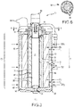
FIG. 3 andFIG. 4 , theOFA 52 includes ahousing 58 having afirst section 60 and conjoinedsecond section 62 distal from thefirst section 60. In various embodiments, a length of thefirst section 60 and a length of thesecond section 62 sum to an overall length OL of thehousing 58. - In the figures, the
OFA 52 is generally oriented vertically, with thefirst section 60 disposed above thesecond section 62. However, any and all position orientations referenced or implied herein (e.g., above, below, bottom, top, etc.) are used as arbitrary reference positions only, based on a convenience of describing the components in the figures; they do not necessarily or preferably refer to the positions of elements with respect to a gravitation pull of the Earth, nor to any other extrinsic and/or intrinsic reference forces to which theOFA 52 is, or maybe, subjected. - Fluid flow (e.g., oil) enters the
OFA 52 through aninlet pipe 64 that is disposed proximate to, and/or within, thefirst section 60 and exits theOFA 52 through anoutlet pipe 66 that is also disposed proximate to, and/or within, thefirst section 60. Theinlet pipe 64 and theoutlet pipe 66 are fluidly connected internally within thehousing 58. - As a fluid (e.g., oil) enters the
OFA 52 through theinlet pipe 64, it flows perpendicularly into thefirst section 60 through a bend, corner, curve, etc. of theinlet pipe 64. This tangential (or substantially tangential) injection imparts a rotational flow (e.g., spin) to the fluid (e.g., oil) relative to a centerline CL as it enters thefirst section 60. More specifically, an angled orientation (e.g., tangential or substantially tangential) of theinlet pipe 64 relative to the centerline CL of theOFA 52 creates a cyclonic effect for the fluid (e.g., oil) as it enters thefirst section 60 of theOFA 52 and travels through thefirst section 60 and into thesecond section 62. After the fluid enters thefirst section 60, at least part of the fluid cyclonically travels down theOFA 52 and into thesecond section 62, which is a continuation of thefirst section 60 of thehousing 58. At a distal end of thesecond section 62, anend cap 68 forces fluid (e.g., oil) back up theOFA 52 towards thefirst section 60 through acenter cavity 70 en-route to theoutlet pipe 66, which is in fluid communication with thefirst section 60 and thesecond section 62 throughout the overall length OL of thehousing 58 and discharges the fluid (e.g., oil) from theOFA 52. - Internally within the
OFA 52, a first (or primary)filter 72 and/or a second (or secondary)filter 74 is/are disposed within thehousing 58, each running substantially the length of thefirst section 60 and the second section 62 (e.g., the overall length OL) of thehousing 58 towards theend cap 68. In various embodiments, theend cap 68 terminates at or about an outer radial limit of thefirst filter 72, thereby generally defining a bottom surface to seat thefirst filter 72 and/or thesecond filter 74 within thehousing 58. In various embodiments, theend cap 68, thefirst filter 72, and/or thesecond filter 74 are bound together, such as with an adhesive or the like. - In various embodiments, the
first filter 72 and/or thesecond filter 74 are primarily annular structures, aligned substantially coaxially and symmetrically along the centerline CL of the OFA 52-e.g., in a nested and/or multi-stage relationship with one another, in various embodiments. - In various embodiments, the
first filter 72 comprises a filter media FM with porous passages disposed between a firstouter surface 76 and a firstinner surface 78. In various embodiments, thefirst filter 72 is a substantially cylindrical outside-in filter, configured such that the firstouter surface 76 is, effectively, a filter inlet, and the firstinner surface 78 is, effectively, a filter outlet. In various embodiments, the fluid (e.g., oil) generally flows from the firstouter surface 76 towards and through the firstinner surface 78, and then generally towards thesecond filter 74. In various embodiments, thefirst filter 72 has multiple outer surfaces and multiple inner surfaces (e.g., seeFIG. 5-A and FIG. 5-B ), for which reference herein to the firstouter surface 76 of thefirst filter 72 generally refers to a part or portion of thefirst filter 72 that extends radially furthest from thefirst filter 72 in relation to the centerline CL, and reference herein to the firstinner surface 78 of thefirst filter 72 generally refers to a part or portion of thefirst filter 72 that extends radially closest from thefirst filter 72 in relation to the centerline CL. - In various embodiments, the
second filter 74 also comprises a filter media FM with porous passages disposed between a secondouter surface 80 and a secondinner surface 82. In various embodiments, thesecond filter 74 is also a substantially cylindrical outside-in filter, configured such that the secondouter surface 80 is, effectively, a filter inlet, and the secondinner surface 82 is, effectively, a filter outlet. In various embodiments, the fluid (e.g., oil) generally flows from the secondouter surface 80 towards and through the secondinner surface 82, and then generally towards thecenter cavity 70. In various embodiments, thesecond filter 74 has multiple outer surfaces and multiple inner surfaces (e.g., seeFIG. 5-A and FIG. 5-B ), for which reference herein to the secondouter surface 80 of thesecond filter 74 generally refers to a part or portion of thesecond filter 74 that extends radially furthest from thesecond filter 74 in relation to the centerline CL, and reference herein to the secondinner surface 82 of thesecond filter 74 generally refers to a part or portion of thesecond filter 74 that extends radially closest from thesecond filter 74 in relation to the centerline CL. - In various embodiments, the second
inner surface 82 of thesecond filter 74 defines thecenter cavity 70, and thecenter cavity 70 forms a hollow core passage directed towards theoutlet pipe 66. In various embodiments, thecenter cavity 70 runs the overall length OL, or substantially the overall length OL, of thehousing 58. In various embodiments, thecenter cavity 70 is shorter than the overall length OL of thehousing 58. In various embodiments, thecenter cavity 70 is longer than the overall length OL of thehousing 58. - In various embodiments, the
housing 58 is generally defined by aninternal surface 84 and anexternal surface 86, comprising a thickness T between theinternal surface 84 and theexternal surface 86. The thickness T is generally defined throughout the overall length OL of thehousing 58, and the thickness T may be the same or different between thefirst section 60 and thesecond section 62, including generally varying over the overall length OL of thehousing 58. - In various embodiments, the first
outer surface 76 of thefirst filter 72 is positioned, spaced, and/or sized internally apart from theinternal surface 84 of thehousing 58 to form an outerannular flow passage 88 between the firstouter surface 76 of thefirst filter 72 and theinternal surface 84 of thehousing 58. - In various embodiments, the outer
annular flow passage 88 extends further than theend cap 68 at the distal end of thesecond section 62 of thehousing 58. - In various embodiments, the first
inner surface 78 of thefirst filter 72 is positioned, spaced, and/or sized internally apart from the secondouter surface 80 of thesecond filter 74 to form an innerannular flow passage 90 between the firstinner surface 78 of thefirst filter 72 and the secondouter surface 80 of thesecond filter 74. - In various embodiments, fluid (e.g., oil) from the
gas turbine engine 10 tangentially enters theOFA 52 at theinlet pipe 64 and flows in and though the outerannular flow passage 88, thefirst filter 72, the innerannular flow passage 90, thesecond filter 74, thecenter cavity 70, and/or theoutlet pipe 66 of theOFA 52, before returning and/or being returned to thegas turbine engine 10 ofFIG. 1 . - In various embodiments, the
first filter 72 and/or thesecond filter 74 are formed with pleated materials as the filter media, such as shown, for example, inFIG. 5-A and 5-B . - In various embodiments, the filter media FM of the
first filter 72 and/or the filter media FM of thesecond filter 74 is/are configured to remove particulate contaminants from the oil as the oil passes through the filter media FM of thefirst filter 72 and/or thesecond filter 74. In various embodiments, the filter media FM of thefirst filter 72 and/or the filter media FM of thesecond filter 74 is/are configured to remove particulate contaminants from the oil before the oil is recirculated back togas turbine engine 10 ofFIG. 1 through theoutlet pipe 66. - In various embodiments, the filter media FM of the
first filter 72 and the filter media FM of thesecond filter 74 are made of the substantially the same materials. In various embodiments, the filter media FM of thefirst filter 72 and the filter media FM of thesecond filter 74 are made of the substantially different materials. In various embodiments, they are configured with the same or different grades and/or levels of filtration capacities (e.g., mesh layers), as well as different lengths and/or radial sizes. - In various embodiments, the
OFA 52 includes one or more filters within thehousing 58, such as thefirst filter 72 and/or thesecond filter 74. In various embodiments, theOFA 52 includes thefirst filter 72 and not thesecond filter 74. In various embodiments, theOFA 52 includes thesecond filter 74 and not thefirst filter 72. In various embodiments, theOFA 52 includes both thefirst filter 72 and thesecond filter 74. In various embodiments, theOFA 52 includes other filters too. - In various embodiments of operation, the
first filter 72 and/or thesecond filter 74 prevent and/or lessen particulate matter from recirculating to thegas turbine engine 10. - In various embodiments of operation, the more particulate matter that the
first filter 72 and/or thesecond filter 74 extract from the fluid (e.g., oil), the less particulate matter that is recirculated back to thegas turbine engine 10. - In various embodiments of operation, the more particulate matter that the
first filter 72 and/or thesecond filter 74 extract from the fluid (e.g., oil), the more often thefirst filter 72 and/or thesecond filter 74 will need to be changed, cleaned, and/or replaced. Conversely, the less particulate matter that thefirst filter 72 and/or thesecond filter 74 extract from the fluid (e.g., oil), the less often thefirst filter 72 and/or thesecond filter 74 will need to be changed, cleaned, and/or replaced. Accordingly, the less particulate matter that impacts thefirst filter 72 and/or thesecond filter 74 improves working lives of thefirst filter 72 and/or thesecond filter 74, provided sufficient particulate matter can be and/or is extracted from the fluid (e.g., oil) to still be able to protect thegas turbine engine 10 as the fluid (e.g., oil) is recirculated from theOFA 52 back through theoutlet pipe 66 and to thegas turbine engine 10. - If particulate matter is extracted from the fluid (e.g., oil) before it impacts the
first filter 72 and/or thesecond filter 74, then thefirst filter 72 and/or thesecond filter 74 will have less particulate matter to extract, in various embodiments. - One way to decrease, lessen, and/or reduce the amount of particulate matter impacting the
first filter 72, and, by extension, also thesecond filter 72 and thegas turbine engine 10, is to pre-separate particulate matter within theOFA 52 before it impacts thefirst filter 72. - In various embodiments, a centrifugal action imparted by the
tangential inlet pipe 64 decreases the amount of particulate matter impacting thefirst filter 72. More specifically, as the fluid (e.g., oil) enters thefirst section 60 of theOFA 52 from theinlet pipe 64, centrifugal forces imparted by theinlet pipe 64 intersecting thehousing 58 of theOFA 52 cause heavier particulate matters to be forced against theinternal surface 84 of thehousing 58 within the outerannular flow passage 88, due to a swirling downward flow of the fluid (e.g., oil) through the outerannular flow passage 88 from thefirst section 60 and/or thesecond section 62. In general, the greater the offset of theinlet pipe 64 relative to thehousing 58 and/or the centerline CL, the greater are the centrifugal forces that are imparted to the fluid (e.g., oil). More specifically, if theinlet pipe 64 is disposed tangentially, or substantially tangentially, to theinternal surface 58 of thehousing 58, then a large amount of centrifugal forces in the entering fluid (e.g., oil) are created, in various embodiments. - As the heavier particulate matters are forced against the
internal surface 84 of thehousing 58 within the outerannular flow passage 88, they are swept down into acollection area 92 disposed towards a bottom of the outerannular flow passage 88, towards a distal end of thesecond section 62 of theOFA 52 relative to thefirst section 60. In various embodiments, the action of the fluid (e.g., oil) within thehousing 58 is that of a downward swirling vortex. This circular, spiraling tornadic motion suspends heavier contamination particles, which are often metal particles, in the outerannular flow passage 88 before they impact thefirst filter 72, and they are carried down towards thecollection area 92. - In various embodiments, the
collection area 92 is proximate theend cap 68. In various embodiments, thecollection area 92 is underneath theend cap 68. In various embodiments, thecollection area 92 is formed between theend cap 68 and a bottom surface of theOFA 52. In various embodiments, thecollection area 92 is annularly shaped like a bowl, extending out from a bottom end of the outerannular flow passage 88 in thesecond section 62 of theOFA 52. - In various embodiments, the
collection area 92 annularly surrounds and/or partially surrounds the bottom or underside of thefirst filter 72 for collecting debris from the outerannular flow passage 88 before it impacts thefirst filter 72 and/orsecond filter 74. - In various embodiments, particulate matter within the fluid (e.g., oil) enters the
first section 60 of theOFA 52 at theinlet pipe 64 and is caused to cyclonically work its way down to the bottom of thesecond section 62 along the outerannular flow passage 88 due to the centrifugal forces on the fluid (e.g., oil) as it travels through the outerannular flow passage 88. Other parts of the fluid (e.g., oil) now have fewer, less, lighter, and/or smaller amounts of particulate matter as they pass through thefirst filter 72, thesecond filter 74, and/or thecenter cavity 70. - The heavier particulate matter is centrifugally forced outward while the relatively cleaner fluid (e.g., oil) impacts the
first filter 72 and/or thesecond filter 74. - At the bottom of the
second section 62 and/or at theend cap 68, the fluid (e.g., oil) reverses its flow and travels back upward through thecenter cavity 70, in various embodiments, leaving the particulate matter as deposited in thecollection area 92 at or towards the bottom of thesecond section 62 of thehousing 58. - In various embodiments, a
drain plug 94 is provided in or near theend cap 68 for draining the fluid (e.g., oil) retained in thehousing 58 before servicing theOFA 52. By accumulating particulate matter within thecollection area 92 before it impacts thefirst filter 72 and/or thesecond filter 74, maintenance intervals for servicing thefirst filter 72 and/or thesecond filter 74 are extended for theOFA 52 and/orgas turbine engine 10 ofFIG. 1 , in various embodiments. - In various embodiments, the
OFA 52 further includes abypass valve 96 proximate theinlet pipe 64 and thefirst section 60 of thehousing 58 for communicatively separating thefirst filter 72 from thesecond filter 74. More specifically, thebypass valve 96 permits and/or forces the fluid (e.g., oil) to bypass thefirst filter 72 and outerannular flow passage 88 and directs the fluid (e.g., oil) only and/or primarily towards thesecond filter 74 and innerannular flow passage 90, such as when thefirst filter 72 and/orcollection area 92 become too dirty or clogged to be effectively used and/or otherwise subject the fluid (e.g., oil) to only a reduced or single level of filtration by thesecond filter 74. For example, if thefirst filter 72 and/or thecollection area 92 become relatively clogged, fluid flow through thefirst filter 72 and/or the outerannular flow passage 88 and/or thecollection area 92 becomes reduced, and pressure in the outerannular flow passage 88 exceeds a threshold, then thebypass valve 96 is forced open, allowing the fluid (e.g., oil) to bypass the outerannular flow passage 88 and only enter the innerannular flow passage 90, in various embodiments. In various embodiments, thebypass valve 96 bypasses thefirst filter 72. In various embodiments, bypassing thefirst filter 72 occurs for only approximately one cycle of (or limited numbers of), or flight(s) with, thegas turbine engine 10 ofFIG. 1 , after which theOFA 52 and/or thefirst filter 72 and/or thecollection area 92 is/are serviced. - In various embodiments, cyclonic pre-separation is combined with filters for removing debris and/or wear particles before recirculating fluid (e.g., oil) to an engine, such as the
gas turbine engine 10 ofFIG. 1 . In various embodiments, the pre-separation occurs before filtration with thefirst filter 72 and/or thesecond filter 74. - For augmenting the cyclonic effect induced by the
tangential inlet pipe 64, a radial width W of the outerannular flow passage 88 gradually varies from thefirst section 60 to thesecond section 62 of theOFA 52 along the overlength OL of thehousing 58. For example, the radial width W of the outerannular flow passage 88 gradually increases from thefirst section 60 to thesecond section 62, which augments the centrifugal force applied to the fluid (e.g., oil) as it moves down theOFA 52 in the direction D, which is generally aligned with the centerline CL of theOFA 52 and extends from thefirst section 60 towards thesecond section 62. As fluid (e.g., oil) enters theOFA 52 through theinlet pipe 64 and travels in the direction D from thefirst section 60 to thesecond section 62, the gradually increasing radial width W of the outerannular flow passage 88 increases the centrifugal force applied to particulate matter travelling through theOFA 52 and forces more of the particulate matter to be driven into thecollection area 92 than would occur if the radial width W of the outerannular flow passage 88 was a constant or decreasing throughout the overall length OL of theOFA 52 in the direction D. - In various embodiments, a first average radial width W1 of the outer
annular flow passage 88 in thefirst section 60 is less than a second average radial width W2 of the outerannular flow passage 88 in the second section 62 (e.g., W1 < W2). - In various embodiments, the first average radial width W1 of the outer
annular flow passage 88 is defined as an average of radial widths W of thefirst section 60, and the second average radial width W2 of the outerannular flow passage 88 is defined as an average of radial widths W of thesecond section 62. - In various embodiments, one configuration to increase the radial width W of the outer
annular flow passage 88 from thefirst section 60 to thesecond section 62 is to decrease the thickness T of thehousing 58 in the direction D. For example, as shown in the embodiment inFIG. 3 , a thickness T of thehousing 58 between theinternal surface 84 and theexternal surface 86 gradually varies from thefirst section 60 to thesecond section 62 of theOFA 52 along the overlength OL of thehousing 58. For example, the thickness T of thehousing 58 gradually decreases from thefirst section 60 to thesecond section 62, thereby allowing the outerannular flow passage 88 to correspondingly increase its radial width W, in various embodiments. - In various embodiments, a first average thickness T1 of the
housing 58 in thefirst section 60 is greater than a second average thickness T2 of thehousing 58 in the second section 62 (e.g., T1 > T2). - In various embodiments, the first average thickness T1 of the
housing 58 is defined as an average of thicknesses T of thefirst section 60, and the second average thickness T2 of thehousing 58 is defined as an average of thicknesses T of thesecond section 62. - In various embodiments, the first average radial width W1 of the outer
annular flow passage 88 in thefirst section 60 plus the first average thickness T1 of thehousing 58 in thefirst section 60 is equal, or substantially equal, to the second average radial width W2 of the outerannular flow passage 88 in thesecond section 62 plus the second average thickness T2 of thehousing 58 in the second section 62 (e.g., W1 + T1 ≈ W2 + T2), such that a first outer diameter OD1 of thehousing 58 in thefirst section 60 is equal, or substantially equal, to a second outer diameter OD2 of thehousing 58 in the second section 62 (e.g., OD1 ≈ OD2). This arrangement allows the outerannular flow passage 88 to increase in radial width W from thefirst section 60 to thesecond section 62 while maintaining a constant or near constant outer diameter OD of thehousing 58 about its overall length OL, in various embodiments, such as shown inFIG. 3 and/or described herein. - Referring now to
FIG. 4 , it is identical, and/or nearly identical, toFIG. 3 in various ways. In both embodiments, for example, the first average radial width W1 of the outerannular flow passage 88 in thefirst section 60 is less than the second average radial width W2 of the outerannular flow passage 88 in the second section 62 (e.g., W1 < W2). In various embodiments, such as inFIG. 3 , this is accomplished by decreasing the first average thickness T1 of thehousing 58 in thefirst section 60 from the second average thickness T2 of thehousing 58 in thesecond section 62 along the direction D. In various embodiments, such as inFIG. 4 , this is accomplished by increasing the first average outer diameter OD1 of thehousing 58 in thefirst section 60 from the second average outer diameter OD2 of thehousing 58 in thesecond section 62 along the direction D (e.g., OD1 < OD2). - More specifically, the first average outer diameter OD1 of the
housing 58 is defined as an average of outer diameters OD of thefirst section 60, and the second average outer diameter OD2 of thehousing 58 is defined as an average of outer diameters OD of thesecond section 62. Accordingly, as the outer diameter OD of thehousing 58 increases in the direction D, theOFA 52 flares generally outwards in thesecond section 62 as compared to thefirst section 60, such that theOFA 52 takes the shape of a partial frustoconical-like structure in itshousing 58, with the outer diameter OD increasing in the direction D from thefirst section 60 towards thesecond section 62. This arrangement allows the outerannular flow passage 88 to increase in radial width W from thefirst section 60 to thesecond section 62 while maintaining a constant thickness T of thehousing 58 about its overall length OL (e.g., T1 ≈ T2), in various embodiments, such as shown inFIG. 4 and/or described herein. - As a convenience to the reader, but not by way of limitation, in
FIG. 3 , W2 > W1, OD1 ≈ OD2, T1 > T2, and W1 + T1 ≈ W2 + T2, and inFIG. 4 , W2 > W1, OD1 < OD2, T1 ≈ T2, and W1 + T1 < W2 + T2-in various embodiments. - For additionally augmenting the cyclonic effect induced by the
tangential inlet pipe 64, theOFA 52 also optionally includes a turningvane assembly 98 disposed in thefirst section 60 proximate theinlet pipe 64, in various embodiments. More specifically, the turningvane assembly 98 includes a plurality of blades 99 (e.g., seeFIG. 6 ) that are configured to spin about the centerline CL so as to further distribute the fluid (e.g., oil) circumferentially into the outerannular flow passage 88 upon entering theOFA 52, thereby increasing the centrifugal effect on the fluid (e.g., oil), in various embodiments. In various embodiments, the turningvane assembly 98 increases the rotational flow of the fluid (e.g., oil) before and/or as it enters thefirst section 60 of theOFA 52. This augmented rotational flow imparts an additional centrifugal force in addition to, and/or instead of, the tangential injection of theinlet pipe 64, in various embodiments. - Referring now to
FIG. 7 , a method 100 (and/or functionality) of filtering particulate matter from a fluid filtration assembly begins at astep 102, after which a fluid is injected into a housing with a centrifugal force at astep 104. In various embodiments, the centrifugal force is augmented within the housing by increasing a width of an outer annular flow passage between a first outer surface of a filter and an internal surface of the housing in astep 106. In various embodiments, particulate matter is collected from the fluid in a collection area due to the augmented centrifugal force before the particulate matter impacts the filter in astep 108, after which themethod 100 ends at astep 110, in various embodiments. - In various embodiments, the
method 100 ofFIG. 7 further comprises discharging the fluid from the housing. In various embodiments, the fluid filtration assembly of themethod 100 ofFIG. 7 is an oil filtration assembly, and/or the fluid is an oil. In various embodiments, the oil filtration assembly is an oil filtration assembly of a gas turbine engine. In various embodiments, themethod 100 ofFIG. 7 further comprises additionally augmenting the centrifugal force by imparting an additional rotational force to the fluid as the fluid enters the housing, such as by a turning valve assembly. - In accordance with the description herein, technical benefits and effects of this disclosure include reducing amounts of debris and/or particulate matter that is introduced to a filter of a fluid filtration assembly, such as an oil filtration assembly, thereby extending and/or increasing the life of the filter, reducing maintenance demands on the filter and/or a gas turbine engine, improving troubleshooting and/or preventive maintenance of the gas turbine engine, enabling different filters and/or filter materials to be used, enabling smaller filters to be used, etc.
- Advantages, benefits, improvements, and solutions, etc. have been described herein with regard to specific embodiments. Furthermore, connecting lines shown in the various figures contained herein are intended to represent exemplary functional relationships and/or physical couplings between the various elements. It should be noted that many additional and/or alternative functional relationships or physical connections may be present in a practical system. However, the advantages, benefits, improvements, solutions, etc., and any elements that may cause any advantage, benefit, improvement, solution, etc. to occur or become more pronounced are not to be construed as critical, essential, or required elements or features of this disclosure.
- The scope of this disclosure is accordingly to be limited by nothing other than the appended claims, in which reference to an element in the singular is not intended to mean "one and only one" unless explicitly so stated, but rather "one or more." It is to be understood that unless specifically stated otherwise, references to "a," "an," and/or "the" may include one or more than one, and that reference to an item in the singular may also include the item in the plural, and vice-versa. All ranges and ratio limits disclosed herein may be combined.
- Moreover, where a phrase similar to "at least one of A, B, and C" is used in the claims, it is intended that the phrase be interpreted to mean that A alone may be present in an embodiment, B alone may be present in an embodiment, C alone may be present in an embodiment, or that any combination of the elements A, B, and C may be present in a single embodiment; for example, A and B, A and C, B and C, or A and B and C. Different cross-hatching may be used throughout the figures to denote different parts, but not necessarily to denote the same or different materials. Like depictions and numerals also generally represent like elements.
- The steps recited in any of the method or process descriptions may be executed in any order and are not necessarily limited to the order presented. Furthermore, any reference to singular elements, embodiments, and/or steps includes plurals thereof, and any reference to more than one element, embodiment, and/or step may include a singular one thereof. Elements and steps in the figures are illustrated for simplicity and clarity and have not necessarily been rendered according to any particular sequence. For example, steps that may be performed concurrently or in different order are only illustrated in the figures to help to improve understanding of embodiments of the present, representative disclosure.
- Any reference to attached, connected, fixed, or the like may include full, partial, permanent, removable, temporary and/or any other possible attachment option. Additionally, any reference to without contact (or similar phrases) may also include reduced contact or minimal contact. Surface shading lines may be used throughout the figures to denote different areas or parts, but not necessarily to denote the same or different materials. In some cases, reference coordinates may or may not be specific to each figure.
- Apparatus, methods, and systems are provided herein. In the detailed description herein, references to "one embodiment," "an embodiment," "various embodiments," etc., indicate that the embodiment described may include a particular characteristic, feature, or structure, but every embodiment may not necessarily include this particular characteristic, feature, or structure. Moreover, such phrases may not necessarily refer to the same embodiment. Further, when a particular characteristic, feature, or structure is described in connection with an embodiment, it is submitted that it is within the knowledge of one skilled in the art to affect such characteristic, feature, or structure in connection with other embodiments, whether or not explicitly described. After reading the description, it will be apparent to one skilled in the relevant art(s) how to implement this disclosure in alternative embodiments.
- Furthermore, no component, element, or method step in the present disclosure is intended to be dedicated to the public regardless of whether the component, element, or method step is explicitly recited in the claims. No claim element is intended to invoke 35 U.S.C. § 112(f) unless the element is expressly recited using the phrase "means for." As used herein, the terms "comprises," "comprising," or any other variation thereof, are intended to cover a non-exclusive inclusion, such that an apparatus, article, method, or process that comprises a list of elements does not include only those elements, but it may also include other elements not expressly listed or inherent to such apparatus, article, method, or process.
Claims (14)
- A fluid filtration assembly, comprising:a housing having a thickness defined between an internal surface of the housing and an external surface of the housing, the housing configured to receive a first filter and define an outer annular flow passage between a first outer surface of the first filter and the internal surface of the housing;an inlet pipe in fluid communication with the fluid filtration assembly, the inlet pipe configured to inject a fluid into the housing to impart a centrifugal force;an outlet pipe in fluid communication with the fluid filtration assembly to discharge the fluid from the housing; anda collection area disposed towards an end of the outer annular flow passage distal the inlet pipe, the collection area configured to collect particulate matter from the fluid;wherein a width of the outer annular flow passage increases towards the collection area.
- The fluid filtration assembly of claim 1, wherein the fluid filtration assembly is an oil filtration assembly and the fluid is an oil.
- A gas turbine engine, comprising:a fan section configured to induce air from a surrounding environment into the gas turbine engine;a compressor section in fluid communication with the fan section and configured to compress the air received from the fan section;a combustor section in fluid communication with the compressor section and configured to ignite a fuel-air mixture to generate combustion gases;a turbine section in fluid communication with the combustor section; anda debris capture device to remove particulate matter from fluids associated with lubricating rotating components of the gas turbine engine, comprising:a housing having a thickness defined between an internal surface of the housing and an external surface of the housing, the housing configured to receive a first filter and define an outer annular flow passage between a first outer surface of the first filter and the internal surface of the housing;an inlet pipe in fluid communication with the oil filtration assembly, the inlet pipe configured to inject an oil into the housing to impart a centrifugal force;an outlet pipe in fluid communication with the oil filtration assembly to discharge the oil from the housing; anda collection area disposed towards an end of the outer annular flow passage distal the inlet pipe, the collection area configured to collect the particulate matter from the oil;wherein a width of the outer annular flow passage increases towards the collection area.
- The fluid filtration assembly of claim 1 or 2 or the gas turbine engine of claim 3, wherein the thickness of the housing decreases towards the collection area.
- The fluid filtration assembly of claim 1, 2 or 4 or the gas turbine engine of claim 3 or 4, wherein an outer diameter of the housing increases towards the collection area.
- The fluid filtration assembly of claim 1, 2, 4 or 5 or the gas turbine engine of any of claims 3 to 5, wherein the width of the outer annular flow passage increases towards the collection area to augment the centrifugal force.
- The fluid filtration assembly of claim 1, 2, 4, 5 or 6 or the gas turbine engine of any of claims 3 to 6, further comprising a drain plug proximate an end cap near the collection area.
- The fluid filtration assembly of claim 1 or 2 or any of claims 4 to 7 or the gas turbine engine of any of claims 3 to 7, further comprising a turning vane assembly proximate the inlet pipe.
- The fluid filtration assembly of claim 1 or 2 or any of claims 4 to 8 or the gas turbine engine of any of claims 3 to 8, further comprising a second filter configured within the first filter.
- A method of filtering particulate matter from a fluid filtration assembly, comprising:injecting a fluid into a housing with a centrifugal force;augmenting the centrifugal force within the housing by increasing a width of an outer annular flow passage between a first outer surface of a filter and an internal surface of the housing; andcollecting particulate matter from the fluid in a collection area due to the augmented centrifugal force before the particulate matter impacts the filter.
- The method of filtering particulate matter from the fluid filtration assembly of claim 10, further comprising discharging the fluid from the housing.
- The method of filtering particulate matter from the fluid filtration assembly of claim 10 or 11, wherein the fluid filtration assembly is an oil filtration assembly and the fluid is an oil.
- The method of filtering particulate matter from the fluid filtration assembly of claim 12, wherein the fluid filtration assembly is a component of a gas turbine engine.
- The method of filtering particulate matter from the fluid filtration assembly of any of claims 11 to 13, further comprising additionally augmenting the centrifugal force by imparting an additional rotational force to the fluid as the fluid enters the housing.
Applications Claiming Priority (1)
| Application Number | Priority Date | Filing Date | Title |
|---|---|---|---|
| US15/973,808 US11073053B2 (en) | 2018-05-08 | 2018-05-08 | Centrifugal debris pre-separator for turbine engine oil filter |
Publications (2)
| Publication Number | Publication Date |
|---|---|
| EP3567227A1 true EP3567227A1 (en) | 2019-11-13 |
| EP3567227B1 EP3567227B1 (en) | 2021-07-07 |
Family
ID=66542020
Family Applications (1)
| Application Number | Title | Priority Date | Filing Date |
|---|---|---|---|
| EP19173338.5A Active EP3567227B1 (en) | 2018-05-08 | 2019-05-08 | Centrifugal debris pre-separator for turbine engine oil filter |
Country Status (2)
| Country | Link |
|---|---|
| US (2) | US11073053B2 (en) |
| EP (1) | EP3567227B1 (en) |
Cited By (1)
| Publication number | Priority date | Publication date | Assignee | Title |
|---|---|---|---|---|
| CN112324575A (en) * | 2020-10-29 | 2021-02-05 | 中国航发南方工业有限公司 | Lubricating oil filter comprising double-acting valve device |
Families Citing this family (5)
| Publication number | Priority date | Publication date | Assignee | Title |
|---|---|---|---|---|
| US11073053B2 (en) * | 2018-05-08 | 2021-07-27 | Raytheon Technologies Corporation | Centrifugal debris pre-separator for turbine engine oil filter |
| US11162494B2 (en) | 2019-01-23 | 2021-11-02 | Pratt & Whitney Canada Corp. | Scavenge pump |
| US11638889B2 (en) | 2019-09-25 | 2023-05-02 | Pratt & Whitney Canada Corp. | Filter cover protection against external contamination |
| US11369908B2 (en) | 2020-01-31 | 2022-06-28 | Pratt & Whitney Canada Corp. | Filter assembly for gas turbine engine |
| CN115559798B (en) * | 2022-12-06 | 2023-03-28 | 河南平和滤清器有限公司 | Oil filter with built-in centrifugal separation structure |
Citations (5)
| Publication number | Priority date | Publication date | Assignee | Title |
|---|---|---|---|---|
| US4298465A (en) * | 1979-06-07 | 1981-11-03 | Racor Industries, Inc. | Fuel filter and water separator apparatus |
| WO1983002072A1 (en) * | 1981-12-11 | 1983-06-23 | Wilson, Peter, C. | Solid bowl centrifuge with intermittent rim discharge |
| DE3941016A1 (en) * | 1988-12-14 | 1990-07-05 | Inst Nadezhnosti I Dolgovecnos | Cyclone filter - having housing, deflection plates, screw conduit, partition wall, central opening, slots, screw-insert, pptn. chamber etc. |
| EP2246529A2 (en) * | 2009-04-27 | 2010-11-03 | Hamilton Sundstrand Corporation | Combined oil filter and debris monitor |
| DE102012219885B3 (en) * | 2012-10-31 | 2014-04-03 | Robert Bosch Gmbh | Liquid filter for fuels in fuel supply system of motor vehicle, has filter element with recess and hydro-cyclone with liquid inlets and liquid outlets, where hydro-cyclone is arranged partially in recess of filter element |
Family Cites Families (14)
| Publication number | Priority date | Publication date | Assignee | Title |
|---|---|---|---|---|
| US1856771A (en) * | 1931-07-22 | 1932-05-03 | Int Motor Co | Combined oil cooler and cleaner |
| US2983384A (en) * | 1958-05-07 | 1961-05-09 | Charles A Winslow | Centrifuging and lubricant-purifying device |
| DE3409219A1 (en) * | 1984-03-14 | 1985-09-19 | Ing. Walter Hengst GmbH & Co KG, 4400 Münster | Oil filter for the cleaning of lubricating oil of a combustion engine |
| US4707165A (en) | 1985-03-04 | 1987-11-17 | Aeroquip Corporation | Gas and fluid separator |
| DE3903675A1 (en) * | 1989-02-08 | 1990-08-09 | Knecht Filterwerke Gmbh | Oil filter for cleaning lubrication oil |
| US5637217A (en) * | 1995-01-25 | 1997-06-10 | Fleetguard, Inc. | Self-driven, cone-stack type centrifuge |
| US5569373A (en) * | 1995-06-28 | 1996-10-29 | Smith; Gerald F. | Reusable fluid filter and adapter |
| US6183407B1 (en) * | 1998-04-02 | 2001-02-06 | Alfa Laval Ab | Centrifugal separator having axially-extending, angled separation discs |
| US6666968B2 (en) | 2001-03-22 | 2003-12-23 | Vortex International, Llc | Fluid filtration apparatus |
| US20050161394A1 (en) * | 2002-11-20 | 2005-07-28 | Karl Fritze | Freeze resistant water filter |
| JP4851851B2 (en) | 2006-06-02 | 2012-01-11 | カヤバ工業株式会社 | Mixer drum drive device |
| DE102009054523A1 (en) * | 2009-12-10 | 2011-06-16 | Hengst Gmbh & Co. Kg | liquid filters |
| US9062611B2 (en) * | 2011-10-19 | 2015-06-23 | United Technologies Corporation | Split accessory drive system |
| US11073053B2 (en) * | 2018-05-08 | 2021-07-27 | Raytheon Technologies Corporation | Centrifugal debris pre-separator for turbine engine oil filter |
-
2018
- 2018-05-08 US US15/973,808 patent/US11073053B2/en active Active
-
2019
- 2019-05-08 EP EP19173338.5A patent/EP3567227B1/en active Active
-
2021
- 2021-05-25 US US17/329,473 patent/US11970960B2/en active Active
Patent Citations (5)
| Publication number | Priority date | Publication date | Assignee | Title |
|---|---|---|---|---|
| US4298465A (en) * | 1979-06-07 | 1981-11-03 | Racor Industries, Inc. | Fuel filter and water separator apparatus |
| WO1983002072A1 (en) * | 1981-12-11 | 1983-06-23 | Wilson, Peter, C. | Solid bowl centrifuge with intermittent rim discharge |
| DE3941016A1 (en) * | 1988-12-14 | 1990-07-05 | Inst Nadezhnosti I Dolgovecnos | Cyclone filter - having housing, deflection plates, screw conduit, partition wall, central opening, slots, screw-insert, pptn. chamber etc. |
| EP2246529A2 (en) * | 2009-04-27 | 2010-11-03 | Hamilton Sundstrand Corporation | Combined oil filter and debris monitor |
| DE102012219885B3 (en) * | 2012-10-31 | 2014-04-03 | Robert Bosch Gmbh | Liquid filter for fuels in fuel supply system of motor vehicle, has filter element with recess and hydro-cyclone with liquid inlets and liquid outlets, where hydro-cyclone is arranged partially in recess of filter element |
Cited By (1)
| Publication number | Priority date | Publication date | Assignee | Title |
|---|---|---|---|---|
| CN112324575A (en) * | 2020-10-29 | 2021-02-05 | 中国航发南方工业有限公司 | Lubricating oil filter comprising double-acting valve device |
Also Published As
| Publication number | Publication date |
|---|---|
| US11970960B2 (en) | 2024-04-30 |
| US20190345853A1 (en) | 2019-11-14 |
| US11073053B2 (en) | 2021-07-27 |
| US20210277811A1 (en) | 2021-09-09 |
| EP3567227B1 (en) | 2021-07-07 |
Similar Documents
| Publication | Publication Date | Title |
|---|---|---|
| US11970960B2 (en) | Centrifugal debris pre-separator for turbine engine oil filter | |
| JP5635296B2 (en) | Assembly, lubricating fluid filtration assembly, cyclone separator, and method for monitoring particulates in a fluid | |
| US6893478B2 (en) | Air/oil separator | |
| US10036319B2 (en) | Separator assembly for a gas turbine engine | |
| US7770375B2 (en) | Particle collector for gas turbine engine | |
| US6451080B1 (en) | Air cleaner | |
| US8992667B2 (en) | Systems and methods for closed crankcase ventilation and air filtration | |
| WO2013067245A1 (en) | Rotating separator with housing preventing separated liquid carryover | |
| EP3324019A1 (en) | A method for scavenging small particles from a turbine engine | |
| EP3597875B1 (en) | Debris separator for a gas turbine engine and corresponding installing method | |
| CN107725139A (en) | Particle piece-rate system | |
| US20200308989A1 (en) | Assembly for particle removal | |
| CN102536461B (en) | In conjunction with the cartridge assembly that turbine engine system uses | |
| CN110139976A (en) | Particle separator component for turbogenerator | |
| CN109139261B (en) | Turbomachine, particle separator system therefor, and method of removing particles | |
| CN108678877A (en) | Air prefilter and air filtration system for engine | |
| EP1820938A1 (en) | Cleaning elements on blade tips of an exhaust turbine | |
| RU2259862C2 (en) | Vortex air cleaner | |
| CN104937223B (en) | The crankcase ventilation self-cleaning coalescer of intermittent rotary | |
| EP4197614A1 (en) | Filter assembly with sedimentation pocket | |
| US2678731A (en) | Separator | |
| WO2018064793A1 (en) | Collection system for a gas turbine engine wash assembly | |
| EP4166213A1 (en) | In-line debris separtor for liquid | |
| Ingistov et al. | Evolution of Gas Turbine Intake Air Filtration in a 420 MW Cogeneration Plant | |
| EP3786420A1 (en) | Dual bypass filter cascade |
Legal Events
| Date | Code | Title | Description |
|---|---|---|---|
| PUAI | Public reference made under article 153(3) epc to a published international application that has entered the european phase |
Free format text: ORIGINAL CODE: 0009012 |
|
| STAA | Information on the status of an ep patent application or granted ep patent |
Free format text: STATUS: THE APPLICATION HAS BEEN PUBLISHED |
|
| AK | Designated contracting states |
Kind code of ref document: A1 Designated state(s): AL AT BE BG CH CY CZ DE DK EE ES FI FR GB GR HR HU IE IS IT LI LT LU LV MC MK MT NL NO PL PT RO RS SE SI SK SM TR |
|
| AX | Request for extension of the european patent |
Extension state: BA ME |
|
| STAA | Information on the status of an ep patent application or granted ep patent |
Free format text: STATUS: REQUEST FOR EXAMINATION WAS MADE |
|
| 17P | Request for examination filed |
Effective date: 20200423 |
|
| RBV | Designated contracting states (corrected) |
Designated state(s): AL AT BE BG CH CY CZ DE DK EE ES FI FR GB GR HR HU IE IS IT LI LT LU LV MC MK MT NL NO PL PT RO RS SE SI SK SM TR |
|
| GRAP | Despatch of communication of intention to grant a patent |
Free format text: ORIGINAL CODE: EPIDOSNIGR1 |
|
| STAA | Information on the status of an ep patent application or granted ep patent |
Free format text: STATUS: GRANT OF PATENT IS INTENDED |
|
| INTG | Intention to grant announced |
Effective date: 20210212 |
|
| RAP1 | Party data changed (applicant data changed or rights of an application transferred) |
Owner name: RAYTHEON TECHNOLOGIES CORPORATION |
|
| GRAS | Grant fee paid |
Free format text: ORIGINAL CODE: EPIDOSNIGR3 |
|
| GRAA | (expected) grant |
Free format text: ORIGINAL CODE: 0009210 |
|
| STAA | Information on the status of an ep patent application or granted ep patent |
Free format text: STATUS: THE PATENT HAS BEEN GRANTED |
|
| AK | Designated contracting states |
Kind code of ref document: B1 Designated state(s): AL AT BE BG CH CY CZ DE DK EE ES FI FR GB GR HR HU IE IS IT LI LT LU LV MC MK MT NL NO PL PT RO RS SE SI SK SM TR |
|
| REG | Reference to a national code |
Ref country code: GB Ref legal event code: FG4D |
|
| REG | Reference to a national code |
Ref country code: AT Ref legal event code: REF Ref document number: 1408789 Country of ref document: AT Kind code of ref document: T Effective date: 20210715 |
|
| REG | Reference to a national code |
Ref country code: DE Ref legal event code: R096 Ref document number: 602019005846 Country of ref document: DE |
|
| REG | Reference to a national code |
Ref country code: IE Ref legal event code: FG4D |
|
| REG | Reference to a national code |
Ref country code: LT Ref legal event code: MG9D |
|
| REG | Reference to a national code |
Ref country code: NL Ref legal event code: MP Effective date: 20210707 |
|
| REG | Reference to a national code |
Ref country code: AT Ref legal event code: MK05 Ref document number: 1408789 Country of ref document: AT Kind code of ref document: T Effective date: 20210707 |
|
| PG25 | Lapsed in a contracting state [announced via postgrant information from national office to epo] |
Ref country code: RS Free format text: LAPSE BECAUSE OF FAILURE TO SUBMIT A TRANSLATION OF THE DESCRIPTION OR TO PAY THE FEE WITHIN THE PRESCRIBED TIME-LIMIT Effective date: 20210707 Ref country code: SE Free format text: LAPSE BECAUSE OF FAILURE TO SUBMIT A TRANSLATION OF THE DESCRIPTION OR TO PAY THE FEE WITHIN THE PRESCRIBED TIME-LIMIT Effective date: 20210707 Ref country code: FI Free format text: LAPSE BECAUSE OF FAILURE TO SUBMIT A TRANSLATION OF THE DESCRIPTION OR TO PAY THE FEE WITHIN THE PRESCRIBED TIME-LIMIT Effective date: 20210707 Ref country code: ES Free format text: LAPSE BECAUSE OF FAILURE TO SUBMIT A TRANSLATION OF THE DESCRIPTION OR TO PAY THE FEE WITHIN THE PRESCRIBED TIME-LIMIT Effective date: 20210707 Ref country code: BG Free format text: LAPSE BECAUSE OF FAILURE TO SUBMIT A TRANSLATION OF THE DESCRIPTION OR TO PAY THE FEE WITHIN THE PRESCRIBED TIME-LIMIT Effective date: 20211007 Ref country code: AT Free format text: LAPSE BECAUSE OF FAILURE TO SUBMIT A TRANSLATION OF THE DESCRIPTION OR TO PAY THE FEE WITHIN THE PRESCRIBED TIME-LIMIT Effective date: 20210707 Ref country code: LT Free format text: LAPSE BECAUSE OF FAILURE TO SUBMIT A TRANSLATION OF THE DESCRIPTION OR TO PAY THE FEE WITHIN THE PRESCRIBED TIME-LIMIT Effective date: 20210707 Ref country code: HR Free format text: LAPSE BECAUSE OF FAILURE TO SUBMIT A TRANSLATION OF THE DESCRIPTION OR TO PAY THE FEE WITHIN THE PRESCRIBED TIME-LIMIT Effective date: 20210707 Ref country code: PT Free format text: LAPSE BECAUSE OF FAILURE TO SUBMIT A TRANSLATION OF THE DESCRIPTION OR TO PAY THE FEE WITHIN THE PRESCRIBED TIME-LIMIT Effective date: 20211108 Ref country code: NO Free format text: LAPSE BECAUSE OF FAILURE TO SUBMIT A TRANSLATION OF THE DESCRIPTION OR TO PAY THE FEE WITHIN THE PRESCRIBED TIME-LIMIT Effective date: 20211007 Ref country code: NL Free format text: LAPSE BECAUSE OF FAILURE TO SUBMIT A TRANSLATION OF THE DESCRIPTION OR TO PAY THE FEE WITHIN THE PRESCRIBED TIME-LIMIT Effective date: 20210707 |
|
| PG25 | Lapsed in a contracting state [announced via postgrant information from national office to epo] |
Ref country code: PL Free format text: LAPSE BECAUSE OF FAILURE TO SUBMIT A TRANSLATION OF THE DESCRIPTION OR TO PAY THE FEE WITHIN THE PRESCRIBED TIME-LIMIT Effective date: 20210707 Ref country code: LV Free format text: LAPSE BECAUSE OF FAILURE TO SUBMIT A TRANSLATION OF THE DESCRIPTION OR TO PAY THE FEE WITHIN THE PRESCRIBED TIME-LIMIT Effective date: 20210707 Ref country code: GR Free format text: LAPSE BECAUSE OF FAILURE TO SUBMIT A TRANSLATION OF THE DESCRIPTION OR TO PAY THE FEE WITHIN THE PRESCRIBED TIME-LIMIT Effective date: 20211008 |
|
| REG | Reference to a national code |
Ref country code: DE Ref legal event code: R097 Ref document number: 602019005846 Country of ref document: DE |
|
| PG25 | Lapsed in a contracting state [announced via postgrant information from national office to epo] |
Ref country code: DK Free format text: LAPSE BECAUSE OF FAILURE TO SUBMIT A TRANSLATION OF THE DESCRIPTION OR TO PAY THE FEE WITHIN THE PRESCRIBED TIME-LIMIT Effective date: 20210707 |
|
| PLBE | No opposition filed within time limit |
Free format text: ORIGINAL CODE: 0009261 |
|
| STAA | Information on the status of an ep patent application or granted ep patent |
Free format text: STATUS: NO OPPOSITION FILED WITHIN TIME LIMIT |
|
| PG25 | Lapsed in a contracting state [announced via postgrant information from national office to epo] |
Ref country code: SM Free format text: LAPSE BECAUSE OF FAILURE TO SUBMIT A TRANSLATION OF THE DESCRIPTION OR TO PAY THE FEE WITHIN THE PRESCRIBED TIME-LIMIT Effective date: 20210707 Ref country code: SK Free format text: LAPSE BECAUSE OF FAILURE TO SUBMIT A TRANSLATION OF THE DESCRIPTION OR TO PAY THE FEE WITHIN THE PRESCRIBED TIME-LIMIT Effective date: 20210707 Ref country code: RO Free format text: LAPSE BECAUSE OF FAILURE TO SUBMIT A TRANSLATION OF THE DESCRIPTION OR TO PAY THE FEE WITHIN THE PRESCRIBED TIME-LIMIT Effective date: 20210707 Ref country code: EE Free format text: LAPSE BECAUSE OF FAILURE TO SUBMIT A TRANSLATION OF THE DESCRIPTION OR TO PAY THE FEE WITHIN THE PRESCRIBED TIME-LIMIT Effective date: 20210707 Ref country code: CZ Free format text: LAPSE BECAUSE OF FAILURE TO SUBMIT A TRANSLATION OF THE DESCRIPTION OR TO PAY THE FEE WITHIN THE PRESCRIBED TIME-LIMIT Effective date: 20210707 Ref country code: AL Free format text: LAPSE BECAUSE OF FAILURE TO SUBMIT A TRANSLATION OF THE DESCRIPTION OR TO PAY THE FEE WITHIN THE PRESCRIBED TIME-LIMIT Effective date: 20210707 |
|
| 26N | No opposition filed |
Effective date: 20220408 |
|
| PG25 | Lapsed in a contracting state [announced via postgrant information from national office to epo] |
Ref country code: IT Free format text: LAPSE BECAUSE OF FAILURE TO SUBMIT A TRANSLATION OF THE DESCRIPTION OR TO PAY THE FEE WITHIN THE PRESCRIBED TIME-LIMIT Effective date: 20210707 |
|
| REG | Reference to a national code |
Ref country code: CH Ref legal event code: PL |
|
| REG | Reference to a national code |
Ref country code: BE Ref legal event code: MM Effective date: 20220531 |
|
| PG25 | Lapsed in a contracting state [announced via postgrant information from national office to epo] |
Ref country code: MC Free format text: LAPSE BECAUSE OF FAILURE TO SUBMIT A TRANSLATION OF THE DESCRIPTION OR TO PAY THE FEE WITHIN THE PRESCRIBED TIME-LIMIT Effective date: 20210707 Ref country code: LU Free format text: LAPSE BECAUSE OF NON-PAYMENT OF DUE FEES Effective date: 20220508 Ref country code: LI Free format text: LAPSE BECAUSE OF NON-PAYMENT OF DUE FEES Effective date: 20220531 Ref country code: CH Free format text: LAPSE BECAUSE OF NON-PAYMENT OF DUE FEES Effective date: 20220531 |
|
| PG25 | Lapsed in a contracting state [announced via postgrant information from national office to epo] |
Ref country code: IE Free format text: LAPSE BECAUSE OF NON-PAYMENT OF DUE FEES Effective date: 20220508 |
|
| PG25 | Lapsed in a contracting state [announced via postgrant information from national office to epo] |
Ref country code: BE Free format text: LAPSE BECAUSE OF NON-PAYMENT OF DUE FEES Effective date: 20220531 |
|
| P01 | Opt-out of the competence of the unified patent court (upc) registered |
Effective date: 20230521 |
|
| PGFP | Annual fee paid to national office [announced via postgrant information from national office to epo] |
Ref country code: FR Payment date: 20230420 Year of fee payment: 5 Ref country code: DE Payment date: 20230419 Year of fee payment: 5 |
|
| PGFP | Annual fee paid to national office [announced via postgrant information from national office to epo] |
Ref country code: GB Payment date: 20230420 Year of fee payment: 5 |
|
| PG25 | Lapsed in a contracting state [announced via postgrant information from national office to epo] |
Ref country code: HU Free format text: LAPSE BECAUSE OF FAILURE TO SUBMIT A TRANSLATION OF THE DESCRIPTION OR TO PAY THE FEE WITHIN THE PRESCRIBED TIME-LIMIT; INVALID AB INITIO Effective date: 20190508 |
|
| PG25 | Lapsed in a contracting state [announced via postgrant information from national office to epo] |
Ref country code: MK Free format text: LAPSE BECAUSE OF FAILURE TO SUBMIT A TRANSLATION OF THE DESCRIPTION OR TO PAY THE FEE WITHIN THE PRESCRIBED TIME-LIMIT Effective date: 20210707 Ref country code: CY Free format text: LAPSE BECAUSE OF FAILURE TO SUBMIT A TRANSLATION OF THE DESCRIPTION OR TO PAY THE FEE WITHIN THE PRESCRIBED TIME-LIMIT Effective date: 20210707 |