EP3566889A1 - Klimaregelungssystem zur erhöhung der reichweite eines elektrofahrzeugs - Google Patents
Klimaregelungssystem zur erhöhung der reichweite eines elektrofahrzeugs Download PDFInfo
- Publication number
- EP3566889A1 EP3566889A1 EP19166243.6A EP19166243A EP3566889A1 EP 3566889 A1 EP3566889 A1 EP 3566889A1 EP 19166243 A EP19166243 A EP 19166243A EP 3566889 A1 EP3566889 A1 EP 3566889A1
- Authority
- EP
- European Patent Office
- Prior art keywords
- refrigerant
- passenger cabin
- control loop
- air
- thermal control
- Prior art date
- Legal status (The legal status is an assumption and is not a legal conclusion. Google has not performed a legal analysis and makes no representation as to the accuracy of the status listed.)
- Withdrawn
Links
Images

Classifications
-
- B—PERFORMING OPERATIONS; TRANSPORTING
- B60—VEHICLES IN GENERAL
- B60H—ARRANGEMENTS OF HEATING, COOLING, VENTILATING OR OTHER AIR-TREATING DEVICES SPECIALLY ADAPTED FOR PASSENGER OR GOODS SPACES OF VEHICLES
- B60H1/00—Heating, cooling or ventilating [HVAC] devices
- B60H1/00642—Control systems or circuits; Control members or indication devices for heating, cooling or ventilating devices
- B60H1/00814—Control systems or circuits characterised by their output, for controlling particular components of the heating, cooling or ventilating installation
- B60H1/00878—Control systems or circuits characterised by their output, for controlling particular components of the heating, cooling or ventilating installation the components being temperature regulating devices
- B60H1/00899—Controlling the flow of liquid in a heat pump system
- B60H1/00921—Controlling the flow of liquid in a heat pump system where the flow direction of the refrigerant does not change and there is an extra subcondenser, e.g. in an air duct
-
- B—PERFORMING OPERATIONS; TRANSPORTING
- B60—VEHICLES IN GENERAL
- B60H—ARRANGEMENTS OF HEATING, COOLING, VENTILATING OR OTHER AIR-TREATING DEVICES SPECIALLY ADAPTED FOR PASSENGER OR GOODS SPACES OF VEHICLES
- B60H1/00—Heating, cooling or ventilating [HVAC] devices
- B60H1/00271—HVAC devices specially adapted for particular vehicle parts or components and being connected to the vehicle HVAC unit
- B60H1/00278—HVAC devices specially adapted for particular vehicle parts or components and being connected to the vehicle HVAC unit for the battery
-
- B—PERFORMING OPERATIONS; TRANSPORTING
- B60—VEHICLES IN GENERAL
- B60H—ARRANGEMENTS OF HEATING, COOLING, VENTILATING OR OTHER AIR-TREATING DEVICES SPECIALLY ADAPTED FOR PASSENGER OR GOODS SPACES OF VEHICLES
- B60H1/00—Heating, cooling or ventilating [HVAC] devices
- B60H1/00357—Air-conditioning arrangements specially adapted for particular vehicles
- B60H1/00385—Air-conditioning arrangements specially adapted for particular vehicles for vehicles having an electrical drive, e.g. hybrid or fuel cell
- B60H1/00392—Air-conditioning arrangements specially adapted for particular vehicles for vehicles having an electrical drive, e.g. hybrid or fuel cell for electric vehicles having only electric drive means
-
- B—PERFORMING OPERATIONS; TRANSPORTING
- B60—VEHICLES IN GENERAL
- B60H—ARRANGEMENTS OF HEATING, COOLING, VENTILATING OR OTHER AIR-TREATING DEVICES SPECIALLY ADAPTED FOR PASSENGER OR GOODS SPACES OF VEHICLES
- B60H1/00—Heating, cooling or ventilating [HVAC] devices
- B60H1/00642—Control systems or circuits; Control members or indication devices for heating, cooling or ventilating devices
- B60H1/00814—Control systems or circuits characterised by their output, for controlling particular components of the heating, cooling or ventilating installation
- B60H1/00821—Control systems or circuits characterised by their output, for controlling particular components of the heating, cooling or ventilating installation the components being ventilating, air admitting or air distributing devices
- B60H1/00835—Damper doors, e.g. position control
- B60H1/00849—Damper doors, e.g. position control for selectively commanding the induction of outside or inside air
-
- B—PERFORMING OPERATIONS; TRANSPORTING
- B60—VEHICLES IN GENERAL
- B60H—ARRANGEMENTS OF HEATING, COOLING, VENTILATING OR OTHER AIR-TREATING DEVICES SPECIALLY ADAPTED FOR PASSENGER OR GOODS SPACES OF VEHICLES
- B60H1/00—Heating, cooling or ventilating [HVAC] devices
- B60H1/00642—Control systems or circuits; Control members or indication devices for heating, cooling or ventilating devices
- B60H1/00814—Control systems or circuits characterised by their output, for controlling particular components of the heating, cooling or ventilating installation
- B60H1/00878—Control systems or circuits characterised by their output, for controlling particular components of the heating, cooling or ventilating installation the components being temperature regulating devices
- B60H1/00885—Controlling the flow of heating or cooling liquid, e.g. valves or pumps
-
- B—PERFORMING OPERATIONS; TRANSPORTING
- B60—VEHICLES IN GENERAL
- B60H—ARRANGEMENTS OF HEATING, COOLING, VENTILATING OR OTHER AIR-TREATING DEVICES SPECIALLY ADAPTED FOR PASSENGER OR GOODS SPACES OF VEHICLES
- B60H1/00—Heating, cooling or ventilating [HVAC] devices
- B60H1/02—Heating, cooling or ventilating [HVAC] devices the heat being derived from the propulsion plant
- B60H1/14—Heating, cooling or ventilating [HVAC] devices the heat being derived from the propulsion plant otherwise than from cooling liquid of the plant, e.g. heat from the grease oil, the brakes, the transmission unit
- B60H1/143—Heating, cooling or ventilating [HVAC] devices the heat being derived from the propulsion plant otherwise than from cooling liquid of the plant, e.g. heat from the grease oil, the brakes, the transmission unit the heat being derived from cooling an electric component, e.g. electric motors, electric circuits, fuel cells or batteries
-
- B—PERFORMING OPERATIONS; TRANSPORTING
- B60—VEHICLES IN GENERAL
- B60H—ARRANGEMENTS OF HEATING, COOLING, VENTILATING OR OTHER AIR-TREATING DEVICES SPECIALLY ADAPTED FOR PASSENGER OR GOODS SPACES OF VEHICLES
- B60H1/00—Heating, cooling or ventilating [HVAC] devices
- B60H1/22—Heating, cooling or ventilating [HVAC] devices the heat being derived otherwise than from the propulsion plant
- B60H1/2215—Heating, cooling or ventilating [HVAC] devices the heat being derived otherwise than from the propulsion plant the heat being derived from electric heaters
- B60H1/2218—Heating, cooling or ventilating [HVAC] devices the heat being derived otherwise than from the propulsion plant the heat being derived from electric heaters controlling the operation of electric heaters
-
- B—PERFORMING OPERATIONS; TRANSPORTING
- B60—VEHICLES IN GENERAL
- B60H—ARRANGEMENTS OF HEATING, COOLING, VENTILATING OR OTHER AIR-TREATING DEVICES SPECIALLY ADAPTED FOR PASSENGER OR GOODS SPACES OF VEHICLES
- B60H1/00—Heating, cooling or ventilating [HVAC] devices
- B60H1/32—Cooling devices
- B60H1/3204—Cooling devices using compression
- B60H1/3228—Cooling devices using compression characterised by refrigerant circuit configurations
- B60H1/32281—Cooling devices using compression characterised by refrigerant circuit configurations comprising a single secondary circuit, e.g. at evaporator or condenser side
-
- B—PERFORMING OPERATIONS; TRANSPORTING
- B60—VEHICLES IN GENERAL
- B60H—ARRANGEMENTS OF HEATING, COOLING, VENTILATING OR OTHER AIR-TREATING DEVICES SPECIALLY ADAPTED FOR PASSENGER OR GOODS SPACES OF VEHICLES
- B60H1/00—Heating, cooling or ventilating [HVAC] devices
- B60H1/32—Cooling devices
- B60H1/3204—Cooling devices using compression
- B60H1/323—Cooling devices using compression characterised by comprising auxiliary or multiple systems, e.g. plurality of evaporators, or by involving auxiliary cooling devices
-
- B—PERFORMING OPERATIONS; TRANSPORTING
- B60—VEHICLES IN GENERAL
- B60H—ARRANGEMENTS OF HEATING, COOLING, VENTILATING OR OTHER AIR-TREATING DEVICES SPECIALLY ADAPTED FOR PASSENGER OR GOODS SPACES OF VEHICLES
- B60H3/00—Other air-treating devices
- B60H3/02—Moistening ; Devices influencing humidity levels, i.e. humidity control
- B60H3/024—Moistening ; Devices influencing humidity levels, i.e. humidity control for only dehumidifying the air
-
- B—PERFORMING OPERATIONS; TRANSPORTING
- B60—VEHICLES IN GENERAL
- B60H—ARRANGEMENTS OF HEATING, COOLING, VENTILATING OR OTHER AIR-TREATING DEVICES SPECIALLY ADAPTED FOR PASSENGER OR GOODS SPACES OF VEHICLES
- B60H1/00—Heating, cooling or ventilating [HVAC] devices
- B60H1/00271—HVAC devices specially adapted for particular vehicle parts or components and being connected to the vehicle HVAC unit
- B60H2001/00307—Component temperature regulation using a liquid flow
-
- B—PERFORMING OPERATIONS; TRANSPORTING
- B60—VEHICLES IN GENERAL
- B60H—ARRANGEMENTS OF HEATING, COOLING, VENTILATING OR OTHER AIR-TREATING DEVICES SPECIALLY ADAPTED FOR PASSENGER OR GOODS SPACES OF VEHICLES
- B60H1/00—Heating, cooling or ventilating [HVAC] devices
- B60H1/00642—Control systems or circuits; Control members or indication devices for heating, cooling or ventilating devices
- B60H1/00814—Control systems or circuits characterised by their output, for controlling particular components of the heating, cooling or ventilating installation
- B60H1/00878—Control systems or circuits characterised by their output, for controlling particular components of the heating, cooling or ventilating installation the components being temperature regulating devices
- B60H2001/00928—Control systems or circuits characterised by their output, for controlling particular components of the heating, cooling or ventilating installation the components being temperature regulating devices comprising a secondary circuit
-
- B—PERFORMING OPERATIONS; TRANSPORTING
- B60—VEHICLES IN GENERAL
- B60H—ARRANGEMENTS OF HEATING, COOLING, VENTILATING OR OTHER AIR-TREATING DEVICES SPECIALLY ADAPTED FOR PASSENGER OR GOODS SPACES OF VEHICLES
- B60H1/00—Heating, cooling or ventilating [HVAC] devices
- B60H1/00642—Control systems or circuits; Control members or indication devices for heating, cooling or ventilating devices
- B60H1/00814—Control systems or circuits characterised by their output, for controlling particular components of the heating, cooling or ventilating installation
- B60H1/00878—Control systems or circuits characterised by their output, for controlling particular components of the heating, cooling or ventilating installation the components being temperature regulating devices
- B60H2001/00949—Control systems or circuits characterised by their output, for controlling particular components of the heating, cooling or ventilating installation the components being temperature regulating devices comprising additional heating/cooling sources, e.g. second evaporator
Definitions
- the present invention relates generally to an electric vehicle and, more particularly, to a method of operating a thermal management system that improves the efficacy and efficiency of an electric vehicle's heating system in order to increase vehicle driving range.
- Electric vehicles due to their reliance on rechargeable batteries, require a relatively sophisticated thermal management system to insure that the batteries remain within their desired operating temperature range. Furthermore, in addition to controlling battery temperature the thermal management system must also be capable of heating and cooling the passenger cabin while not unduly affecting the vehicle's overall operating efficiency.
- U.S. Patent No. 6,360,835 discloses a thermal management system for use with a fuel-cell-powered vehicle, the system utilizing both low and high temperature heat transfer circuits that share a common heat transfer medium, the dual circuits required to adequately cool the vehicle's exothermic components and heat the vehicle's endothermic components.
- U.S. Patent No. 7,789,176 discloses a thermal management system that utilizes multiple cooling loops and a single heat exchanger.
- one cooling loop is used to cool the energy storage system
- a second cooling loop corresponds to the HVAC subsystem
- a third cooling loop corresponds to the drive motor cooling system.
- the use of a heater coupled to the first cooling loop is also disclosed, the heater providing a means for insuring that the batteries are warm enough during initial vehicle operation or when exposed to very low ambient temperatures.
- U.S. Patent No. 8,336,319 discloses an EV dual mode thermal management system designed to optimize efficiency between two coolant loops, the first cooling loop in thermal communication with the vehicle's batteries and the second cooling loop in thermal communication with at least one drive train component such as an electric motor or an inverter.
- the disclosed system uses a dual mode valve system to configure the thermal management system between a first mode and a second mode of operation, where in the first mode the two cooling loops operate in parallel and in the second mode the two cooling loops operate in series.
- the present invention provides a method for using a heat pump refrigeration system to remove moisture from a vehicle's cabin air, thereby allowing the vehicle's HVAC system to recirculate passenger cabin air and thus reduce energy consumption. Reducing energy consumption leads to substantial improvements in an electric vehicle's driving range, especially under cold weather conditions.
- Another aspect of the invention allows thermal energy to be stored within an electric vehicle's battery pack, thermal energy that can then be extracted by the HVAC system's heat pump.
- the HVAC system's heat pump can be used to extract and use waste heat from the vehicle's powertrain and power electronics.
- a first calculation could be termed a second calculation, and, similarly, a first step could be termed a second step, and, similarly, a first component could be termed a second component, without departing from the scope of this disclosure.
- HVAC heating, ventilation, and air conditioning
- IC internal combustion
- a thermal control loop 101 containing a heat transfer fluid, e.g., a liquid coolant is thermally coupled to IC engine 103.
- IC engine 103 heats the heat transfer fluid contained within thermal loop 101 which is then circulated through a liquid-air heat exchanger 105 using coolant pump 107.
- Heat exchanger 105 is positioned such that air entering the vehicle, for example along pathway 109, is heated as it passes through the heat exchanger and prior to entering cabin 111, thereby providing a simple means of providing heat to the passenger cabin.
- the amount of air passing through heat exchanger 105, rather than being diverted around heat exchanger 105, is controlled by an air flow controller 113, where air flow controller 113 may be comprised of one or more vanes, shutters, baffles, or other means.
- air flow controller 113 may be comprised of one or more vanes, shutters, baffles, or other means.
- the amount of air flowing through heat exchanger 105, or diverted around heat exchanger 105 is also controlled using one or more fans (not shown), for example fans located at the air intake, within an air conduit/channel, or otherwise positioned to control air flow.
- fans not shown in the exemplary HVAC system shown in Fig.
- multiple air control surfaces 115 e.g., conduits, channels, dash board components, etc.
- Louvers 119 are typically used to control the amount of air passing through each air flow pathway 117.
- Exemplary HVAC system 100 also includes a refrigerant-based thermal control loop 121.
- Control loop 121 includes a compressor 123 to compress the low temperature vapor contained within the loop into a high temperature vapor and a condenser 125 in which a portion of the captured heat is dissipated. After passing through condenser 125, the refrigerant changes phases from vapor to liquid, the liquid remaining at a temperature below the saturation temperature at the prevailing pressure.
- the refrigerant thermal loop is coupled to a refrigerant-air heat exchanger 127 via thermal expansion valve 129 which controls the flow rate of refrigerant into heat exchanger 127.
- Heat exchanger 127 also referred to herein as an evaporator, provides a means for cooling the air within passenger cabin 111. Additionally, in cold weather evaporator 127 and the same refrigeration system may be used to remove moisture from the incoming air before it is heated by heat exchanger 105, thus reducing window fogging. Both of these processes, i.e., cooling the passenger cabin and dehumidifying incoming air, remove heat from the HVAC supply air.
- thermal control loop 101 and heat exchanger 105 are used to heat incoming air to a comfortable temperature, after which the heated air is forced into the passenger cabin via one or more of a plurality of air vents (e.g., air flow pathways 117).
- the warm air within passenger cabin 111 is exhausted through one or more exhaust vents (see, for example, exhaust vents 201 in Fig. 2 ).
- exhaust vents 201 in Fig. 2 the heat contained within the exhaust air is not recirculated back to the passenger cabin.
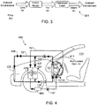
- Fig. 3 illustrates the overall energy flow path used during cold weather of HVAC system 100.
- the vehicle's HVAC system utilizes a heat pump 401.
- the heat pump system has the ability to provide both cooling and heating using the refrigeration system. Additionally, and in accordance with the invention, the heat pump system is used to (i) remove the moisture in the cabin air using evaporator 127, and (ii) recycle the thermal energy removed from the evaporator through the heat pump condenser 403 and transfer it back to the recirculated cabin air.
- This process achieves two benefits; first, the system recirculates the thermal energy obtained from the moisture removal process back into the cabin instead of expelling it to the ambient environment, and two, the system recirculates the cabin air on very cold days while reducing the chances for window fogging. By recirculating warmed cabin air rather than expelling it to the outside environment, energy use for cabin heating can be substantially reduced, leading to an increase in EV driving range when ambient temperatures are low (e.g., winter).
- Fig. 4 illustrates a HVAC system 400 suitable for use with the invention, system 400 utilizing a heat pump 401 that can be used to provide both passenger cabin heating and cooling.
- system 400 includes two condensers, the outside condenser 125 as in the previously illustrated HVAC system, and a heat pump condenser 403.
- the HVAC system 400 is operating in the cooling mode, i.e., when the ambient temperatures are high, the refrigerant-based thermal control loop 121 operates as previously described, providing cool air to passenger cabin 111 via heat exchanger 127 (i.e., the cooling system's evaporator).
- shut-off valve 405 When HVAC system 400 is operated in this mode, shut-off valve 405 is kept open while shut-off valve 407 is kept closed, thereby directing the refrigerant to outside condenser 125 and allowing the captured heat to be expelled to the ambient environment.
- shut-off valve 405 is closed and shut-off valve 407 is open, thereby allowing the high pressure, high temperature refrigerant within thermal loop 121 to flow through heat pump condenser 403.
- the heat pump condenser 403 can be a liquid cooled condenser as shown where the heat removed from the evaporator is transferred to the coolant flowing through the heat pump condenser. Additional heat can be added to the cabin heating loop 101 using a supplemental heater 409 disposed in the same coolant loop.
- Warm humid air from the passenger cabin (see exemplary air path 411) is circulated through the HVAC system with the refrigeration loop running.
- the warm humid air first enters evaporator 127.
- the air entering evaporator 127 is cooled to a low temperature, preferably just above the triple point of water (i.e., 0.01 °C). By cooling the warm humid air, moisture is removed.
- Compressor 123 then pumps the thermal energy removed from evaporator 127, including the latent heat of moisture, through shut-off valve 407 and to the heat pump condenser.
- the thermal energy removed from the evaporator and the thermal energy equivalent of compressor power is then transferred to the coolant (or air) and this heat is eventually used to re-heat the recirculated air as it passes through liquid-air heat exchanger 105.
- supplementary heater 409 can be used to provide additional heat via liquid-air heat exchanger 105.
- the refrigerant After passing through the heat pump, the refrigerant is expanded to a lower temperature (pressure) using expansion valve 129, thus allowing the cycle to continue.
- an air side inner condenser could be used to directly heat air.
- the above-described HVAC system can also be used to reduce energy consumption during hot days when the HVAC system is operating in the cooling mode.
- the humid air must first be cooled to a low temperature sufficient to remove moisture from the air (for example, cooled to the triple point of water, i.e., 0.01 °C). Then the air must be re-heated to the temperature requested by the vehicle's occupants.
- a portion of the thermal energy from evaporator 127 can be transferred back to coolant loop 121 using the heat pump condenser. This energy can then be used to reheat the dehumidified air to the desired temperature using liquid-air heat exchanger 105.
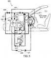
- the vehicle is an EV and the HVAC system 500 includes a battery chiller 501 that can extract thermal energy from the battery pack 503. Additionally, in this configuration thermal energy can be stored within the vehicle's battery pack, for example by elevating the battery pack temperature by the desired amount (e.g., typically in the range of 5° to 30° C) when the vehicle is plugged into an external charging energy source.
- the desired amount e.g., typically in the range of 5° to 30° C
- the disclosed system can also be used to heat battery pack 503 to insure that the battery is operating in the preferred operating temperature range.
- Battery pack 503 can be heated using heater 409 and combining the battery and passenger cabin coolant loops.
- the battery pack can utilize an independent battery heater, thus allowing the battery and passenger cabin coolant loops to remain separate.
- the battery pack can also be heated by other means such as through the process of charging or discharging.
- the energy stored in battery pack 503 can be recovered from a thermally conditioned battery through the battery chiller 501 that is in thermal contact with the battery pack, either in direct thermal contact or through a battery pack coolant system.
- a second expansion valve 505 is used to expand the refrigerant through the battery chiller, thereby extracting the thermal energy stored within the battery pack. This thermal energy is transferred to the coolant or directly to the passenger cabin air via heat pump condenser 403. Alternately, the expansion can be done through the battery chiller and the evaporator simultaneously.
- thermal energy from the battery pack While the preferred embodiment of the heat pump system extracts thermal energy from the battery pack, it should be understood that this same approach can be used to extract thermal energy from the propulsion powertrain(s) and/or associated electronics, although the amount of waste heat generated by the powertrain/electronics is typically much less than that generated by the battery pack.
- the extraction of thermal energy from the powertrain and/or power electronics can be done in addition to, or in lieu of, extracting thermal energy from the battery pack.
- this potential source(s) of additional thermal energy is represented by chiller 507, which is in thermal contact with the powertrain and/or power electronics 509 and coupled to the heat pump system via expansion valve 511. Note that while separate chillers are shown, a single chiller can be used with both the battery pack and the powertrain/power electronics, assuming the single chiller is thermally coupled to both the battery pack and the powertrain/power electronics.
- cabin air can be recirculated through the HVAC system, thereby lowering the amount of energy required to maintain the desired cabin temperature.
- the inventors have found that making several 30 minute trips on extremely cold days can reduce the driving range by 15 to 30%, assuming that the passenger cabin is heated to a comfortable temperature range.
- the impact is much larger, up to 40%, for EVs with a relatively low driving range.
- using the battery pack as a thermal energy storage as described above can further extend the range of the EV by 5 to 10% since less electric energy is consumed in heating the passenger cabin.
- using powertrain waste heat recovery can further extend the range of the electric vehicle by 5 to 10%, as less electric energy is consumed in heating the passenger cabin.
- the powertrain waste heat recovery approach is more beneficial during long drives.
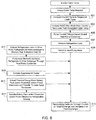
- Fig. 6 illustrates the methodology associated with a HVAC system that includes a heat pump in accordance with the invention.
- determination of whether to operate the HVAC system in the cooling mode or the heating mode is the result of comparing the current passenger cabin air temperature with a requested cabin air temperature (step 601).
- the requested cabin air temperature is typically input by adjusting a thermostat, where the thermostat interface may be a touch screen, a dial, or other means. If the HVAC system determines that the current air temperature is less than that desired, the HVAC system activates the heat mode (step 603).
- coolant is pumped through the heat pump condenser 403 (step 605), the refrigeration loop 121 is activated (step 607), and the system is switched to the heat pump mode (609). Additionally, valve 407 is opened (step 611) while the outside condenser 125 is decoupled from refrigerant-based thermal control loop 121, thereby allowing the high pressure, high temperature refrigerant within thermal loop 121 to flow through heat pump condenser 403.
- step 613 moisture is removed via refrigerant-air heat exchanger 127 and heated via liquid-air heat exchanger 105. If necessary and as noted above, additional heat can be added to the cabin heating loop 101 using supplemental heater 409 (step 615). Alternately, or in addition to the supplemental heater, refrigeration cooling of the battery pack and/or powertrain and/or power electronics can be initiated (step 617), thereby allowing thermal energy to be extracted from the battery pack and/or powertrain and/or power electronics and transferred to the heat pump condenser (step 619).
- supplemental heater 409 step 615
- refrigeration cooling of the battery pack and/or powertrain and/or power electronics can be initiated (step 617), thereby allowing thermal energy to be extracted from the battery pack and/or powertrain and/or power electronics and transferred to the heat pump condenser (step 619).
Applications Claiming Priority (2)
| Application Number | Priority Date | Filing Date | Title |
|---|---|---|---|
| US201862762496P | 2018-05-07 | 2018-05-07 | |
| US16/014,889 US20190381861A1 (en) | 2018-05-07 | 2018-06-21 | Climate Control System for Increased Electric Vehicle Range |
Publications (1)
| Publication Number | Publication Date |
|---|---|
| EP3566889A1 true EP3566889A1 (de) | 2019-11-13 |
Family
ID=66041260
Family Applications (1)
| Application Number | Title | Priority Date | Filing Date |
|---|---|---|---|
| EP19166243.6A Withdrawn EP3566889A1 (de) | 2018-05-07 | 2019-03-29 | Klimaregelungssystem zur erhöhung der reichweite eines elektrofahrzeugs |
Country Status (3)
| Country | Link |
|---|---|
| US (1) | US20190381861A1 (de) |
| EP (1) | EP3566889A1 (de) |
| CN (1) | CN110450596A (de) |
Cited By (2)
| Publication number | Priority date | Publication date | Assignee | Title |
|---|---|---|---|---|
| US20200282806A1 (en) * | 2019-03-04 | 2020-09-10 | Denso International America, Inc. | Heating and cooling system |
| CN113085485A (zh) * | 2021-04-29 | 2021-07-09 | 吉林大学 | 一种纯电动汽车用整车集成化热管理系统 |
Families Citing this family (1)
| Publication number | Priority date | Publication date | Assignee | Title |
|---|---|---|---|---|
| JP7018853B2 (ja) * | 2018-09-05 | 2022-02-14 | 本田技研工業株式会社 | 情報提供装置、情報提供方法、及びプログラム |
Citations (8)
| Publication number | Priority date | Publication date | Assignee | Title |
|---|---|---|---|---|
| US6042016A (en) * | 1994-07-06 | 2000-03-28 | Sanden Corporation | Air conditioner for vehicles |
| US6360835B1 (en) | 2000-02-16 | 2002-03-26 | General Motors Corporation | Thermal management of fuel-cell-powered vehicles |
| US7789176B2 (en) | 2007-04-11 | 2010-09-07 | Tesla Motors, Inc. | Electric vehicle thermal management system |
| US8336319B2 (en) | 2010-06-04 | 2012-12-25 | Tesla Motors, Inc. | Thermal management system with dual mode coolant loops |
| FR2991435A1 (fr) * | 2012-05-31 | 2013-12-06 | Valeo Systemes Thermiques | Installation de chauffage, ventilation et/ou climatisation pour vehicule automobile et procede de mise en oeuvre d'une telle installation. |
| US20140060102A1 (en) * | 2012-09-04 | 2014-03-06 | GM Global Technology Operations LLC | Mild ambient vehicular heat pump system |
| WO2015039924A1 (fr) * | 2013-09-19 | 2015-03-26 | Valeo Systemes Thermiques | Installation de chauffage, ventilation et/ou climatisation pour habitacle de véhicule automobile |
| US20170174038A1 (en) * | 2014-09-09 | 2017-06-22 | Bayerische Motoren Werke Aktiengesellschaft | Heat Pump System for Climate Control of a Vehicle, and Method for Operating a Heat Pump System of This Type |
Family Cites Families (10)
| Publication number | Priority date | Publication date | Assignee | Title |
|---|---|---|---|---|
| DE102010000990B4 (de) * | 2010-01-19 | 2018-01-11 | Hanon Systems | Verfahren zum Betrieb eines Klimatisierungssystems |
| US9925877B2 (en) * | 2011-01-21 | 2018-03-27 | Sanden Holdings Corporation | Vehicle air conditioning apparatus |
| US20130227973A1 (en) * | 2012-03-05 | 2013-09-05 | Halla Climate Control Corporation | Heat pump system for vehicle and method of controlling the same |
| JP6112039B2 (ja) * | 2013-04-08 | 2017-04-12 | 株式会社デンソー | 車両用熱管理システム |
| US10183550B2 (en) * | 2013-08-26 | 2019-01-22 | Ford Global Technologies, Llc | Method and system for heating a vehicle |
| US9358856B2 (en) * | 2013-10-03 | 2016-06-07 | Ford Global Technologies, Llc | System off configuration for climate control system |
| US9758011B2 (en) * | 2014-10-21 | 2017-09-12 | Atieva, Inc. | EV multi-mode thermal management system |
| DE102015218824A1 (de) * | 2015-09-30 | 2017-03-30 | Bayerische Motoren Werke Aktiengesellschaft | Wärmepumpensystem und Verfahren zum Betrieb eines solchen |
| US20180222286A1 (en) * | 2017-02-09 | 2018-08-09 | Ford Global Technologies, Llc | Method to heat the cabin while cooling the battery during fast charge |
| US11046148B2 (en) * | 2017-04-26 | 2021-06-29 | Hanon Systems | Air conditioner for vehicles |
-
2018
- 2018-06-21 US US16/014,889 patent/US20190381861A1/en not_active Abandoned
-
2019
- 2019-03-29 EP EP19166243.6A patent/EP3566889A1/de not_active Withdrawn
- 2019-05-05 CN CN201910366867.1A patent/CN110450596A/zh active Pending
Patent Citations (8)
| Publication number | Priority date | Publication date | Assignee | Title |
|---|---|---|---|---|
| US6042016A (en) * | 1994-07-06 | 2000-03-28 | Sanden Corporation | Air conditioner for vehicles |
| US6360835B1 (en) | 2000-02-16 | 2002-03-26 | General Motors Corporation | Thermal management of fuel-cell-powered vehicles |
| US7789176B2 (en) | 2007-04-11 | 2010-09-07 | Tesla Motors, Inc. | Electric vehicle thermal management system |
| US8336319B2 (en) | 2010-06-04 | 2012-12-25 | Tesla Motors, Inc. | Thermal management system with dual mode coolant loops |
| FR2991435A1 (fr) * | 2012-05-31 | 2013-12-06 | Valeo Systemes Thermiques | Installation de chauffage, ventilation et/ou climatisation pour vehicule automobile et procede de mise en oeuvre d'une telle installation. |
| US20140060102A1 (en) * | 2012-09-04 | 2014-03-06 | GM Global Technology Operations LLC | Mild ambient vehicular heat pump system |
| WO2015039924A1 (fr) * | 2013-09-19 | 2015-03-26 | Valeo Systemes Thermiques | Installation de chauffage, ventilation et/ou climatisation pour habitacle de véhicule automobile |
| US20170174038A1 (en) * | 2014-09-09 | 2017-06-22 | Bayerische Motoren Werke Aktiengesellschaft | Heat Pump System for Climate Control of a Vehicle, and Method for Operating a Heat Pump System of This Type |
Cited By (2)
| Publication number | Priority date | Publication date | Assignee | Title |
|---|---|---|---|---|
| US20200282806A1 (en) * | 2019-03-04 | 2020-09-10 | Denso International America, Inc. | Heating and cooling system |
| CN113085485A (zh) * | 2021-04-29 | 2021-07-09 | 吉林大学 | 一种纯电动汽车用整车集成化热管理系统 |
Also Published As
| Publication number | Publication date |
|---|---|
| CN110450596A (zh) | 2019-11-15 |
| US20190381861A1 (en) | 2019-12-19 |
Similar Documents
| Publication | Publication Date | Title |
|---|---|---|
| EP3088230B1 (de) | Mehrfachmodus-wärmesteuerungssystem eines elektrischen fahrzeugs | |
| JP5599654B2 (ja) | 空調ループと熱媒流路とを含む熱管理システム | |
| CN111615464B (zh) | 车用空调装置 | |
| US11794548B2 (en) | Vehicle air conditioning device | |
| JP5860361B2 (ja) | 電動車両用熱管理システム | |
| US10371419B2 (en) | Vehicle air conditioner with programmed flow controller | |
| JP5867305B2 (ja) | 車両用熱管理システム | |
| US11772449B2 (en) | Vehicle air conditioning device | |
| US8371512B2 (en) | Electrical or hybrid motor vehicle with thermal conditioning system upgrading low-level sources | |
| JP5996779B2 (ja) | バッテリの温度を制御するための装置を備える加熱、換気および/または空調装置、並びに、その実施方法 | |
| CN107867143B (zh) | 将热能传递至分配向车辆客舱的空气的方法 | |
| US20150202986A1 (en) | Thermal management system for electric vehicle and its control method | |
| CN102476572B (zh) | 车辆用温度控制装置 | |
| KR20180065311A (ko) | 차량용 열관리 시스템 | |
| EP3566889A1 (de) | Klimaregelungssystem zur erhöhung der reichweite eines elektrofahrzeugs | |
| JP5552166B2 (ja) | 車輌用空調システム、およびこのシステムの運転モードに応じた実行プロセス | |
| CN114144320A (zh) | 车辆装设发热设备的温度调节装置及包括该装置的车用空调装置 | |
| US20150233627A1 (en) | Method and system for reducing the possibility of vehicle heat exchanger freezing | |
| CN109466274B (zh) | 一种用于电动汽车的热管理系统 | |
| CN111051096B (zh) | 车辆用空气调节装置 | |
| CN113352840A (zh) | 车辆的热管理系统 | |
| CN113811727B (zh) | 车辆用空气调节装置 | |
| CN210337493U (zh) | 一种电动车辆的热管理系统 | |
| KR20220152604A (ko) | 차량의 열관리 시스템 | |
| CN219406082U (zh) | 热管理系统及车辆 |
Legal Events
| Date | Code | Title | Description |
|---|---|---|---|
| PUAI | Public reference made under article 153(3) epc to a published international application that has entered the european phase |
Free format text: ORIGINAL CODE: 0009012 |
|
| 17P | Request for examination filed |
Effective date: 20190329 |
|
| AK | Designated contracting states |
Kind code of ref document: A1 Designated state(s): AL AT BE BG CH CY CZ DE DK EE ES FI FR GB GR HR HU IE IS IT LI LT LU LV MC MK MT NL NO PL PT RO RS SE SI SK SM TR |
|
| AX | Request for extension of the european patent |
Extension state: BA ME |
|
| STAA | Information on the status of an ep patent application or granted ep patent |
Free format text: STATUS: THE APPLICATION IS DEEMED TO BE WITHDRAWN |
|
| 18D | Application deemed to be withdrawn |
Effective date: 20200603 |