EP3566680B1 - Controlled deployable medical device - Google Patents
Controlled deployable medical device Download PDFInfo
- Publication number
- EP3566680B1 EP3566680B1 EP19181564.6A EP19181564A EP3566680B1 EP 3566680 B1 EP3566680 B1 EP 3566680B1 EP 19181564 A EP19181564 A EP 19181564A EP 3566680 B1 EP3566680 B1 EP 3566680B1
- Authority
- EP
- European Patent Office
- Prior art keywords
- stent
- movable element
- end portion
- medical apparatus
- tube
- Prior art date
- Legal status (The legal status is an assumption and is not a legal conclusion. Google has not performed a legal analysis and makes no representation as to the accuracy of the status listed.)
- Active
Links
Images


Classifications
-
- A—HUMAN NECESSITIES
- A61—MEDICAL OR VETERINARY SCIENCE; HYGIENE
- A61F—FILTERS IMPLANTABLE INTO BLOOD VESSELS; PROSTHESES; DEVICES PROVIDING PATENCY TO, OR PREVENTING COLLAPSING OF, TUBULAR STRUCTURES OF THE BODY, e.g. STENTS; ORTHOPAEDIC, NURSING OR CONTRACEPTIVE DEVICES; FOMENTATION; TREATMENT OR PROTECTION OF EYES OR EARS; BANDAGES, DRESSINGS OR ABSORBENT PADS; FIRST-AID KITS
- A61F2/00—Filters implantable into blood vessels; Prostheses, i.e. artificial substitutes or replacements for parts of the body; Appliances for connecting them with the body; Devices providing patency to, or preventing collapsing of, tubular structures of the body, e.g. stents
- A61F2/95—Instruments specially adapted for placement or removal of stents or stent-grafts
- A61F2/954—Instruments specially adapted for placement or removal of stents or stent-grafts for placing stents or stent-grafts in a bifurcation
-
- A—HUMAN NECESSITIES
- A61—MEDICAL OR VETERINARY SCIENCE; HYGIENE
- A61F—FILTERS IMPLANTABLE INTO BLOOD VESSELS; PROSTHESES; DEVICES PROVIDING PATENCY TO, OR PREVENTING COLLAPSING OF, TUBULAR STRUCTURES OF THE BODY, e.g. STENTS; ORTHOPAEDIC, NURSING OR CONTRACEPTIVE DEVICES; FOMENTATION; TREATMENT OR PROTECTION OF EYES OR EARS; BANDAGES, DRESSINGS OR ABSORBENT PADS; FIRST-AID KITS
- A61F2/00—Filters implantable into blood vessels; Prostheses, i.e. artificial substitutes or replacements for parts of the body; Appliances for connecting them with the body; Devices providing patency to, or preventing collapsing of, tubular structures of the body, e.g. stents
- A61F2/95—Instruments specially adapted for placement or removal of stents or stent-grafts
- A61F2/958—Inflatable balloons for placing stents or stent-grafts
-
- A—HUMAN NECESSITIES
- A61—MEDICAL OR VETERINARY SCIENCE; HYGIENE
- A61F—FILTERS IMPLANTABLE INTO BLOOD VESSELS; PROSTHESES; DEVICES PROVIDING PATENCY TO, OR PREVENTING COLLAPSING OF, TUBULAR STRUCTURES OF THE BODY, e.g. STENTS; ORTHOPAEDIC, NURSING OR CONTRACEPTIVE DEVICES; FOMENTATION; TREATMENT OR PROTECTION OF EYES OR EARS; BANDAGES, DRESSINGS OR ABSORBENT PADS; FIRST-AID KITS
- A61F2/00—Filters implantable into blood vessels; Prostheses, i.e. artificial substitutes or replacements for parts of the body; Appliances for connecting them with the body; Devices providing patency to, or preventing collapsing of, tubular structures of the body, e.g. stents
- A61F2/02—Prostheses implantable into the body
- A61F2/04—Hollow or tubular parts of organs, e.g. bladders, tracheae, bronchi or bile ducts
- A61F2/06—Blood vessels
- A61F2/07—Stent-grafts
-
- A—HUMAN NECESSITIES
- A61—MEDICAL OR VETERINARY SCIENCE; HYGIENE
- A61F—FILTERS IMPLANTABLE INTO BLOOD VESSELS; PROSTHESES; DEVICES PROVIDING PATENCY TO, OR PREVENTING COLLAPSING OF, TUBULAR STRUCTURES OF THE BODY, e.g. STENTS; ORTHOPAEDIC, NURSING OR CONTRACEPTIVE DEVICES; FOMENTATION; TREATMENT OR PROTECTION OF EYES OR EARS; BANDAGES, DRESSINGS OR ABSORBENT PADS; FIRST-AID KITS
- A61F2/00—Filters implantable into blood vessels; Prostheses, i.e. artificial substitutes or replacements for parts of the body; Appliances for connecting them with the body; Devices providing patency to, or preventing collapsing of, tubular structures of the body, e.g. stents
- A61F2/02—Prostheses implantable into the body
- A61F2/04—Hollow or tubular parts of organs, e.g. bladders, tracheae, bronchi or bile ducts
- A61F2/06—Blood vessels
- A61F2002/065—Y-shaped blood vessels
-
- A—HUMAN NECESSITIES
- A61—MEDICAL OR VETERINARY SCIENCE; HYGIENE
- A61F—FILTERS IMPLANTABLE INTO BLOOD VESSELS; PROSTHESES; DEVICES PROVIDING PATENCY TO, OR PREVENTING COLLAPSING OF, TUBULAR STRUCTURES OF THE BODY, e.g. STENTS; ORTHOPAEDIC, NURSING OR CONTRACEPTIVE DEVICES; FOMENTATION; TREATMENT OR PROTECTION OF EYES OR EARS; BANDAGES, DRESSINGS OR ABSORBENT PADS; FIRST-AID KITS
- A61F2/00—Filters implantable into blood vessels; Prostheses, i.e. artificial substitutes or replacements for parts of the body; Appliances for connecting them with the body; Devices providing patency to, or preventing collapsing of, tubular structures of the body, e.g. stents
- A61F2/95—Instruments specially adapted for placement or removal of stents or stent-grafts
- A61F2002/9505—Instruments specially adapted for placement or removal of stents or stent-grafts having retaining means other than an outer sleeve, e.g. male-female connector between stent and instrument
- A61F2002/9511—Instruments specially adapted for placement or removal of stents or stent-grafts having retaining means other than an outer sleeve, e.g. male-female connector between stent and instrument the retaining means being filaments or wires
-
- A—HUMAN NECESSITIES
- A61—MEDICAL OR VETERINARY SCIENCE; HYGIENE
- A61F—FILTERS IMPLANTABLE INTO BLOOD VESSELS; PROSTHESES; DEVICES PROVIDING PATENCY TO, OR PREVENTING COLLAPSING OF, TUBULAR STRUCTURES OF THE BODY, e.g. STENTS; ORTHOPAEDIC, NURSING OR CONTRACEPTIVE DEVICES; FOMENTATION; TREATMENT OR PROTECTION OF EYES OR EARS; BANDAGES, DRESSINGS OR ABSORBENT PADS; FIRST-AID KITS
- A61F2/00—Filters implantable into blood vessels; Prostheses, i.e. artificial substitutes or replacements for parts of the body; Appliances for connecting them with the body; Devices providing patency to, or preventing collapsing of, tubular structures of the body, e.g. stents
- A61F2/95—Instruments specially adapted for placement or removal of stents or stent-grafts
- A61F2002/9534—Instruments specially adapted for placement or removal of stents or stent-grafts for repositioning of stents
Definitions
- the invention relates generally to devices that are retained inside a body passage and in one particular application to vascular devices used in repairing arterial dilations, e.g. aneurysms. More particularly, the invention is directed toward devices that can be adjusted during deployment, thereby allowing at least one of a longitudinal or radial repositioning of the device prior to final placement of the device.
- the invention will be discussed generally with respect to deployment of a bifurcated stent graft into the abdominal aorta but is not so limited and may apply to device deployment into other body lumens.
- Typical stent grafts used to repair an aortic aneurysm incorporate a proximal (i.e. portion of the stent graft closest to the heart) anchoring system intended to limit longitudinal displacement of the stent graft.
- this anchoring system must be precisely placed to avoid occlusion of a branch vessel or to avoid placement within a compromised and damaged portion of the aortic wall.
- WO 97/03624 discloses a graft apparatus, delivery devices and methods for use in stent-graft systems for use in treating aneurysms occurring in hollow-body organs or vessels, and for treating arteriovenous fistulas.
- An apparatus for use with a stent for treating an aneurysm is disclosed, the apparatus comprising a graft; a delivery device including an introducer catheter and a manipulation lead, the manipulation lead disposed within and extending distally from the introducer catheter; and means for releasably engaging the graft to the manipulation lead for adjusting the position of the graft after the graft is deployed from the introducer catheter.
- An improved delivery system for such stent grafts would include a means for allowing precise longitudinal and rotational placement of the stent graft and anchoring system. The precise position of the stent graft and anchoring system would be adjusted and visualized prior to full deployment of the device. Ideally the delivery system would allow the device to be repositioned if the prior deployment position was undesirable.
- the present invention is directed to a controlled deployable medical device according to claim 1.
- the invention relates generally to a novel medical apparatus that includes a device capable of being retained inside a body passage and in one particular application to vascular devices. More particularly,the invention is directed toward devices that can be adjusted during deployment, thereby allowing at least one of a longitudinal or radial repositioning of the device.
- the medical apparatus includes a catheter assembly having a proximal end portion and distal end portion.
- a hub can optionally be arranged on the distal end portion of the catheter assembly.
- a stent is arranged on the proximal end portion of the catheter.
- the stent has an inner surface and an outer surface.
- the stent can be any suitable configuration.
- the stent is configured from multiple turns of an undulating element.
- a graft member can be arranged about at least a portion of the stent.
- the stent may be self-expandable, balloon-expandable or a combination of self-expandable and balloon-expandable.
- a tube extends from the proximal end portion to the distal end portion of the catheter.
- a first movable element having a first and second end, is arranged around the outer surface of the stent. The first and second end of the first movable element are capable of extending out the distal end portion of the tube and the first movable element is capable of radially compressing at least a portion of the stent.
- a second movable element can be in communication with the first movable element, wherein the second movable element is arranged around the outer surface of stent and the first movable element is looped over the second movable element.
- a sheath material can cover at least a portion of the stent, wherein the sheath material is capable of holding the stent at a first diameter.
- a filament can surround the stent and a pin can extend from the tube and is capable of holding the filament surrounding the stent at a second diameter which is greater than the first diameter. The pin extending from the tube is capable of releasing the filament surrounding the stent to a third diameter which is greater than the second diameter.
- the stents can be used to at least fix the medical apparatus inside a portion of patient's anatomy.
- the stent can be constructed from materials that are flexible and strong.
- the stent can be formed from, for example, degradable bioabsorable materials, biodigestible materials, polymeric materials, metallic materials and combinations thereof.
- these materials may be reinforced and/or coated with other materials, such as polymeric materials and the like.
- the coating may be chosen to reduce acidic or basic effects of the gastrointestinal tract, e.g., with a thermoplastic coating such as ePTFE and the like.
- the stents can be fabricated using any suitable methods and materials.
- stents can be fabricated according to the teachings as generally disclosed in United States Patent No. 6,042,605 issued to Martin, et al. , United States Patent No. 6,361,637 issued to Martin, et al. and United States Patent No. 6,520,986 issued to Martin, et al.
- stents can have various configurations as known in the art and can be fabricated, for example, from cut tubes, wound wires (or ribbons), flat patterned sheets rolled into a tubular form, combinations thereof, and the like.
- Stents can be formed from metallic, polymeric or natural materials and can comprise conventional medical grade materials such as nylon, polyacrylamide, polycarbonate, polyethylene, polyformaldehyde, polymethylmethacrylate, polypropylene, polytetrafluoroethylene, polytrifluorochlorethylene, polyvinylchloride, polyurethane, elastomeric organosilicone polymers; metals such as stainless steels, cobalt-chromium alloys and nitinol and biologically derived materials such as bovine arteries/veins, pericardium and collagen.
- conventional medical grade materials such as nylon, polyacrylamide, polycarbonate, polyethylene, polyformaldehyde, polymethylmethacrylate, polypropylene, polytetrafluoroethylene, polytrifluorochlorethylene, polyvinylchloride, polyurethane, elastomeric organosilicone polymers
- metals such as stainless steels, cobalt-chromium alloys and nitin
- Stents can also comprise bioresorbable materials such as poly(amino acids), poly(anhydrides), poly(caprolactones), poly(lactic/glycolic acid) polymers, poly(hydroxybutyrates) and poly(orthoesters).
- bioresorbable materials such as poly(amino acids), poly(anhydrides), poly(caprolactones), poly(lactic/glycolic acid) polymers, poly(hydroxybutyrates) and poly(orthoesters).
- the stents can be formed into a variety of different geometric configurations having constant and/or varied thickness as known in the art.
- the geometric configurations may include many conventional stent configurations such as a helically wrapped stent, z-shape stent, tapered stent, coil stent, combinations thereof, and the like.
- the stents can be formed in a variety of patterns, such as, a helix pattern, ring pattern, combinations thereof, and the like.
- Grafts can have various configurations as known in the art and can be fabricated, for example, from tubes, sheets or films formed into tubular shapes, woven or knitted fibers or ribbons or combinations thereof. Graft materials can include, for example, conventional medical grade materials such as nylon, polyester, polyethylene, polypropylene, polytetrafluoroethylene, polyvinylchloride, polyurethane and elastomeric organosilicone polymers.
- Stents can be used alone or in combination with graft materials. Stents can be configured on the external or internal surface of a graft or may be incorporated into the internal wall structure of a graft. Stent or stent grafts can be delivered endoluminally by various catheter based procedures known in the art. For example self-expanding endoluminal devices can be compressed and maintained in a constrained state by an external sheath. The sheath can be folded to form a tube positioned external to the compressed device. The sheath edges can be sewn together with a deployment cord that forms a "chain stitch".
- Constraining sheaths and deployment cord stitching can be configured to release a self-expanding device in several ways.
- a constraining sheath may release a device starting from the proximal device end, terminating at the distal device end. In other configurations the device may be released starting from the distal end.
- Self expanding devices may also be released from the device center as the sheath disrupts toward the device distal and proximal ends.
- the catheter and hub assemblies can comprise conventional medical grade materials such as nylon, polyacrylamide, polycarbonate, polyethylene, polyformaldehyde, polymethylmethacrylate, polypropylene, polytetrafluoroethylene, polytrifluorochlorethylene, polyether block amide or thermoplastic copolyether, polyvinylchloride, polyurethane, elastomeric organosilicone polymers, and metals such as stainless steels and nitinol.
- conventional medical grade materials such as nylon, polyacrylamide, polycarbonate, polyethylene, polyformaldehyde, polymethylmethacrylate, polypropylene, polytetrafluoroethylene, polytrifluorochlorethylene, polyether block amide or thermoplastic copolyether, polyvinylchloride, polyurethane, elastomeric organosilicone polymers, and metals such as stainless steels and nitinol.
- FIG. 1A is a medical apparatus according to an embodiment of the invention.
- FIG. 1B is an enlarged simplified view of a portion of the medical apparatus shown in FIG. 1A .
- the medical apparatus 100A includes catheter assembly 102, stent 104 arranged on the proximal end portion of the catheter assembly 102.
- the stent 104 has an inner surface, an outer surface, and in this embodiment is configured from multiple turns of an undulating element 105.
- the undulating element 105 can be configured, for example, in a ring or helical pattern.
- the stent 104 has a proximal end portion 106 and distal end portion 108.
- the distal end portion 108 is formed into a branch having a first leg 110 and a second leg 112.
- a graft member 114 is arranged about the stent 104.
- the stent 104 and graft member 114 are constrained into a compacted delivery state by a first sheath 116 and second sheath 118. As shown in FIG. 1A , the first sheath 116 has been released, allowing at least a portion of the stent 104 to expand as shown.
- the second sheath 118 is coupling the second leg 112 to the catheter assembly 102 as shown.
- a tube 120 extends from a proximal end portion to a distal end portion of the catheter assembly 102.
- the tube 120 is positioned adjacent the outer surface of the stent 104 and graft 114.
- the tube 120 is attached to the catheter assembly 102 and not attached to the stent 104 or graft 114,
- a movable element 122 e.g., a fiber cord, string, wire, etc. having a first end 124 and second end 126 surrounds the stent 104 and graft member 114.
- the first end 124 and second end 126 of the movable element 122 extend out a distal end portion of the tube 120.
- the movable element 122 is threaded through the tube from a distal end to a proximal end and is looped around the proximal end portion 106 of the stent 104 and graft member 114. As shown in FIG. 1B , by pulling the first end 124 and the second end 126 in a distal direction the movable element 122 is capable of radially compressing at least a portion of the stent 104 as indicated by arrows 128.
- FIG. 1C is a medical apparatus according to an embodiment of the invention
- FIG. 1D is an enlarged simplified view of a portion of the medical apparatus shown as FIG. 1C .
- the medical apparatus is generally depicted as reference numeral 100B,
- the medical apparatus of FIGS. 1C and 1D is similar to the medical apparatus as shown in FIGS 1A and 1B .
- the medical apparatus includes catheter assembly 102, stent 104 arranged on the proximal end portion of catheter assembly 102.
- Stent 104 has an inner surface, an outer surface, and is configured from multiple turns of an undulating element 105.
- the undulating element 105 may be configured, for example, in a ring or helical pattern.
- the stent 104 has a proximal end portion 106 and distal end portion 108.
- the distal end portion 108 is formed into a branch having a first leg 110 and a second leg 112.
- a graft member 114 is arranged about the stent 104,
- the stent 104 and graft member 114 are constrained into a compacted delivery state by a first sheath 116 and second sheath 118. As shown in FIG. 1C , the first sheath 116 has been released allowing at least a portion of the stent to expand as shown The second sheath 118 is coupling the second leg 112 to the catheter assembly 102 as shown.
- a tube 120 extends from a proximal end portion to a distal end portion of the catheter assembly 102.
- the tube 120 is positioned adjacent the outer surface of the stent 104 and graft 114.
- the tube 120 is attached to the catheter assembly 102 and not attached to the stent 104 or graft 114.
- a movable element 122A having a first end 124 and second end 126 surrounds the stent 104 and graft member 114.
- the first end 124 and second end 126 of the movable element 122A extend out a distal end portion of the tube 120.
- the movable element 122A is threaded through the tube from a distal end to a proximal end and is looped around the proximal end portion 106 of the stent 104 and graft member 114.
- an additional movable element 122B having first end 132 and second end 134 surrounds the stent 104 and graft member 114.
- the first end 132 and second end 134 of the additional movable element 122B extend out a distal end portion of the tube 120.
- the additional movable element 122B is threaded through the tube from a distal end to an intermediate opening 136 in the tube 120 and is looped around an intermediate portion of the stent 104 and graft member 114. As shown in FIG.
- the movable element 122A and the additional movable element 122B are capable of radially compressing at least a portion of the stent 104 as indicated by arrows 128, It should be understood that additional moveable elements can be provided.
- FIG. 2A is a medical apparatus according to an embodiment of the invention, shown in a partially deployed state.
- FIG. 2B is an enlarged simplified view of a portion of the medical apparatus shown in FIG. 2A .
- the medical apparatus 200A includes a catheter assembly 202, and stent 204 arranged on the proximal end portion of the catheter assembly 202.
- the stent 204 has an inner surface, an outer surface, and is configured from multiple turns of an undulating element 205.
- the undulating element 205 can be configured, for example, in a ring or helical pattern.
- the stent 204 has a proximal end portion 206 and distal end portion 208.
- the distal end portion 208 is formed into a branch having a first leg 210 and a second leg 212.
- a graft member 214 is arranged about the stent 204.
- the stent 204 and graft member 214 are constrained into a compacted delivery state by a first sheath 216 and second sheath 218. As shown in FIG. 2A , the first sheath 216 has been released allowing at least a portion of the stent to expand.
- the second sheath 218 is coupling the second leg 212 to the catheter assembly 202 as shown.
- a tube 220 extends from a proximal end portion to a distal end portion of the catheter assembly 202.
- the tube 220 is positioned adjacent the outer surface of the stent 204 and graft 214.
- the tube 220 is attached to the catheter assembly 202 and not attached to the stent 204 or graft 214.
- a second movable element 236 is in communication with a first movable element 222.
- the second movable element 236 surrounds the stent 204 and the first movable element 222 is looped through the second movable element 236.
- the first end 224 and second end 226 of the first movable element 222 extend out a distal end portion of the tube 220.
- the first movable element 222 is threaded through the tube from a distal end to a proximal end and is looped through the second movable element 236.
- the movable element 222 pulls on the second movable element 236, radially compressing at least a portion of the stent 204 as indicated by arrows 228.
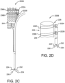
- FIG. 2C is a medical apparatus according to an embodiment of the invention.
- FIG. 2D is an enlarged simplified view of a portion of the medical apparatus shown in FIG. 2C .
- the medical apparatus is generally depicted by reference numeral 200B.
- the medical apparatus of FIGS 2C and 2D is similar to the medical apparatus as shown in FIGS 2A and 2B .
- a second movable element 236A is in communication with a first movable element 222A.
- the second movable element 236A surrounds the stent 204 and the first movable element 222A is looped through the second movable element 236A.
- An additional first movable element 222B along with an additional second movable element 236B are incorporated into the medical apparatus 200B.
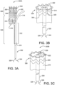
- FIG. 3A is a medical apparatus according to an aspect of the invention.
- FIG. 3B is an enlarged simplified view of a portion of the medical apparatus shown in FIG. 3A .
- the medical apparatus 300A includes a catheter assembly 302, and stent 304 arranged on the proximal end portion of the catheter assembly 302.
- the stent 304 has an inner surface, an outer surface, and is configured from multiple turns of an undulating element 305.
- the undulating element 305 may be configured in a ring or helical pattern.
- the stent 304 has a proximal end portion 306 and distal end portion 308.
- the distal end portion 308 is formed into a branch having a first leg 310 and a second leg 312.
- a graft 314 is arranged about the stent 104,
- the stent 304 and graft 314 are constrained into a compacted delivery state by a first sheath 316 and second sheath 318.
- first sheath 316 has been released allowing at least a portion of the stent 304 to expand as shown.
- the second sheath 318 is coupling the second leg 312 to the catheter assembly 302 as shown.
- a tube 320 extends from a proximal end portion to a distal end portion of the catheter assembly 302, The tube 320 is positioned within and surrounded by the stent 304. The tube 320 is attached to the catheter assembly 302 and not attached to the stent 304 or graft 314.
- a movable element 322 having a first end 324 and second end 326 surrounds the stent 304 and graft 314. The first end 324 and second end 326 of the movable element 322 extend out a distal end portion of the tube 320.
- the movable element 322 is threaded through the tube from a distal end to a proximal end and is looped around the proximal end portion 306 of the stent 304 and graft 314.
- a further embodiment for "surrounding" the stent with the moveable element includes threading the moveable element 322 through the graft 314 or through the stent 304 as shown in FIG. 3B .
- the movable element 322 is capable of radially compressing at least a portion of the stent 304 as indicated by arrows 328 when tension is applied to the movable element ends 324 and 326. Additional movable elements may be added similar to those configurations described in FIGS. 1D and 2D .
- FIG. 3C is an enlarged simplified view of a portion of a medical apparatus according to an embodiment of the invention.
- second movable element 336 is in communication with first movable element 322.
- the second movable element 336 surrounds the stent member 304 and the first movable element 322 is looped through the second movable element 336.
- the second movable element 336 may also be threaded through the graft 314 or threaded through the stent 304 as shown in FIG. 3C .
- the first end 324 and second end 326 of the first movable element 322 extend out a distal end portion of the tube 320.
- the first movable element 322 is threaded through the tube from a distal end to a proximal end and is looped through the second movable element 336.
- the first movable element 322 pulls on the second movable element 336, radially compressing at least a portion of the stent 304 as indicated by arrows 328. Additional movable elements may be added similar to those configurations described in FIGS. 1D and 2D .
- FIG. 4A is a medical apparatus according to an embodiment of the invention.
- FIG. 4B is an enlarged simplified view of a portion of the medical apparatus shown in FIG. 4A .
- the medical apparatus 400 includes a catheter assembly 402, and stent 404 arranged on the proximal end portion of the catheter assembly 402,
- the stent 404 has an inner surface, an outer surface, and is configured from multiple turns of an undulating element 405.
- the undulating element 405 may be configured in a ring or helical pattern.
- the stent 404 has a proximal end portion 406 and distal end portion 408.
- the distal end portion 408 is formed into a branch having a first leg 410 and a second leg 412.
- a graft 414 is arranged about the stent 404.
- the stent 404 and graft 414 are constrained into a compacted delivery state by a first sheath 416 and second sheath 418. As shown in FIG. 4A , the first sheath 416 has been released allowing at least a portion of the stent 404 to expand as shown.
- the second sheath 418 is coupling the second leg 412 to the catheter assembly 402 as shown.
- a tube 420 extends from a proximal end portion to a distal end portion of the catheter assembly 402.
- the tube 420 is positioned adjacent the outer surface of the stent 404 and graft 414.
- the tube 420 is attached to the catheter assembly 402 and not attached to the stent 404 or graft 414.
- a second movable element 436 is in communication with a first movable element 422.
- the second movable element 436 surrounds the stent 404.
- the second movable element 436 is looped through the first movable element 422.
- a release pin 450 is threaded through the second movable element 436, thereby releasably attaching the second movable element 436 to the first movable element 422.
- the first end 424 and second end 426 of the first movable element 422 extend out a distal end portion of the tube 420 along with the distal end of the release pin 450.
- the release pin 450 can be translated in a distal direction as shown by direction arrow 452, thereby releasing the second movable element 436 from the first movable element 422.
- FIG. 5A is a medical apparatus according to an embodiment of the invention.
- FIG. 5B is an enlarged simplified view of a portion of the medical apparatus shown in FIG. 5A .
- the medical apparatus 500 includes a catheter assembly 502, and stent 504 arranged on the proximal end portion of the catheter assembly 502.
- the stent 504 has an inner surface, an outer surface, and is configured from multiple turns of an undulating element 505.
- the undulating element 505 may be configured in a ring or helical pattern.
- the stent 504 has a proximal end portion 506 and distal end portion 508.
- the distal end portion 508 is formed into a branch having a first leg 510 and a second leg 512.
- a graft 514 is arranged about the stent 504.
- the stent 504 and graft 514 are constrained into a compacted delivery state by a first sheath 516 and second sheath 518.
- first sheath 516 has been released allowing at least a portion of the stent 504 to expand as shown.
- the second sheath 518 is coupling the second leg 512 to the catheter assembly 502 as shown.
- a tube 520 extends from a proximal end portion to a distal end portion of the catheter assembly 502.
- the tube 520 is positioned adjacent the outer surface of the stent 504 and graft 514.
- the tube 520 is attached to the catheter assembly 502 and not attached to the stent 504 or graft 514.
- a movable element 522 is threaded through the tube 520 and is circumferentially arranged around the stent 504. The movable element 522 is looped over release pin 550, thereby releasably attaching the movable element 522 to the release pin 550.
- the movable element 522 when tension is applied to the two ends 524 and 526 of the movable element, the movable element 522 radially compresses at least a portion of the stent as previously shown, for example, in FIG. 2B .
- the release pin 550 can be translated in a distal direction as shown by direction arrow 552, thereby releasing the movable element 522 from the release pin 550 allowing the movable element 522 to be withdrawn.
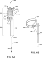
- FIG. 6A is a medical apparatus according to an embodiment of the invention.
- FIG. 6B is an enlarged simplified view of a portion of the medical apparatus shown in FIG. 6A .
- the medical apparatus 600 includes a catheter assembly 602, and stent 604 arranged on the proximal end portion of the catheter assembly 602.
- the stent 604 has an inner surface, an outer surface, and is configured from multiple turns of an undulating element 605.
- the undulating element 605 may be configured in a ring or helical pattern.
- the stent 604 has a proximal end portion 606 and distal end portion 608.
- the distal end portion 608 is formed into a branch having a first leg 610 and a second leg 612.
- a graft 614 is arranged about the stent 604.
- the stent 604 and graft 614 are constrained into a compacted delivery state (or first diameter) by a first sheath 616 and second sheath 618.
- first sheath 616 has been released allowing at least a portion of the stent 604 to expand as shown.
- the second sheath 618 is coupling the second leg 612 to the catheter assembly 602 as shown.
- the stent 604 is allowed to self expand into a second diameter that is greater than the initial compacted first diameter.
- the second diameter is defined by a secondary constraint 654.
- the secondary constraint 654 can be comprised, for example, of a flexible filament that encircles a proximal end portion 606 of the stent and graft. The secondary constraint 654 prevents further self expansion of the stent.
- the secondary constraint 654 is looped around the stent (not shown) and is threaded through a first end of the secondary constraint 654.
- the second end of the secondary constraint 654 is looped onto a release pin 650.
- the secondary constraint 654 can be released by translating the release pin 650 in a distal direction as shown by direction arrow 652. By translating the release pin 650, the stent is released from the secondary constraint and thereby allowed to further expand into a third diameter that is greater than the second and first diameters.
- a retrieval cord or filament 656 can be used to join the secondary constraint 654 to the release pin 650. Therefore when the release pin is translated distally, the secondary constraint 654 is withdrawn along with the release pin 650.
- FIG. 7A is a medical apparatus according to an embodiment of the invention.
- FIG. 7B is an enlarged simplified view of a portion of the medical apparatus shown in FIG. 7A .
- the medical apparatus 700 includes a catheter assembly 702, and stent 704 arranged on the proximal end portion of the catheter assembly 702.
- the stent 704 has an inner surface, an outer surface, and is configured from multiple turns of an undulating element 705.
- the undulating element 705 may be configured in a ring or helical pattern.
- the stent 704 has a proximal end portion 706 and distal end portion 708.
- the distal end portion 708 is formed into a branch having a first leg 710 and a second leg 712.
- a graft 714 is arranged about the stent 704.
- the stent 704 and graft 714 are constrained into a compacted delivery state (or first diameter) by a first sheath 716 and second sheath 718.
- first sheath 716 has been released allowing at least a portion of the stent 704 to expand as shown
- the second sheath 718 is coupling the second leg 712 to the catheter assembly 702 as shown.
- the stent 704 is allowed to self expand into a second diameter that is greater than the initial compacted first diameter.
- the second diameter is defined by a secondary constraint 754.
- the secondary constraint 754 is comprised of a flexible band that encircles a proximal end portion 706 of the stent graft. The secondary constraint prevents further self expansion of the stent graft.
- the secondary constraint 754 is looped around the stent and is threaded through a latch 758 located near a first end of the secondary constraint 754.
- a release pin 750 is threaded through the latch 758 to prevent further expansion of the secondary constraint 754.
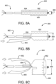
- FIGS. 8A through 8C depict a medical apparatus according to an embodiment of the invention.
- the medical apparatus is generally depicted as reference numeral 800.
- the medical apparatus 800 includes a catheter assembly 802, and stent arranged on the proximal end portion of the catheter assembly 802.
- the medical apparatus 800 has a stent constrained into a small delivery diameter 856.
- the stent is held in this small delivery diameter by constraining sheaths 850 and 854.
- the sheath 850 constrains the trunk of the stent while the sheath 854 constrains the extended leg portion of the stent.
- a third constraining sheath 852 is contained within the sheath 850.
- the sheath 850 when the medical apparatus 800 is positioned within a target site, the sheath 850 can be released, allowing at least a portion of the stent to expand to a diameter 858 that is larger than the initial small delivery diameter 856.
- the sheath 852 therefore constrains the stent 804 to an intermediate diameter.
- the sheath 854 constrains the extended leg portion of the stent onto the catheter assembly 802, thereby allowing the medical apparatus to be repositioned, rotated or precisely aligned to the target site.
- FIG. 8C when the medical apparatus is precisely positioned, the sheath 852 can be released, allowing the stent to fully expand to a large deployed diameter 860.
- the deployed diameter 860 is larger than the intermediate diameter 858.
- the intermediate diameter 858 is larger than the delivery diameter 856 as shown in FIGS. 8A through 8C .
- Stent anchoring barbs or hooks 862 are therefore constrained to the intermediate diameter 858 during final manipulation and positioning of the medical apparatus and allowed to expand and engage a vessel when the constraining sheath 852 is released.
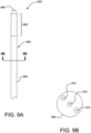
- FIG. 9A is a partial side view of a medical apparatus 900, having a constrained medical device 960 located near or at the distal end of a catheter assembly 962.
- the catheter assembly 962 has a catheter shaft 964 and a distal guidewire port 966.
- FIG 9B is a cross-sectional view of the catheter shaft 964. Shown contained within the catheter shaft 964 is a guidewire 970, a release member 972 and an adjustment member 974.
- the release member can be a cord, thread, wire, pin, tube or other element used to release a stent (or other medical device) from a constraint, thereby allowing the device to expand from a first compacted delivery profile to a second larger profile.
- the adjustment member can be a cord, thread, wire, pin, tube or other element used to alter the second profile of at least a portion of the medical device.
- a catheter used to deliver a medical apparatus can have one, two, three, four or five or more release members combined with one, two, three, four or five or more adjustment members.
- the release members and adjustment members can be contained in separate or shared lumens within the catheter shaft 964.
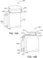
- FIGURES 10A and 10B show generalized views of a medical apparatus according to an embodiment of the invention (previously described in FIGURES 2A and 2B ).
- a medical apparatus 1000 comprised of a stent 1002 having anchor barbs or hooks 1004.
- a tube 1006 having a first movable element 1008 located therein.
- the first movable element 1008 is shown looped through a second movable element 1010.
- tension 1012 is applied to the ends of the first movable element 1008, the second movable element 1010 is drawn into the tube 1006.
- the stent graft is compressed in the direction indicated by arrows 1014.
- the anchors or barbs 1004 are therefore retracted and pulled inwardly away from a vessel wall.
- the retraction of the anchors or barbs will allow the medical apparatus 1000 to be longitudinally and/or rotationally adjusted.
- the tension 1012 on the movable element can be removed, allowing the stent to self expand and engage the anchors or barbs into a vessel wall.
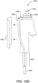
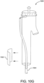
- FIGURES 10C through 10H show a generalized delivery sequence. Shown in FIG. 10C is a medical apparatus 1000, having a first constraining sheath 1020, a second constraining sheath 1022 and a catheter assembly 1024. Constrained and contained within the first and second sheaths 1020, 1022 is a bifurcated stent having a trunk, a first short leg and a second long leg. As shown in FIG. 10D , when the medical apparatus is positioned at a target site, the first constraining sheath 1020 is released allowing a portion of the stent and first short leg to self expand. A portion of the stent is held in a constrained small diameter state by movable element 1026.
- the movable element 1026 is located in tube 1028.
- the stent anchors or barbs 1030 are constrained and pulled inwardly by the movable element 1026, so that the anchors or barbs do not engage a vessel wall.
- the second constraining sheath 1022 compresses the stent graft second long leg onto the catheter assembly 1024.
- the medical apparatus 1000 can now be readjusted in the longitudinal direction 1032 and/or in the angular direction 1034 through manipulations of the catheter assembly 1024.
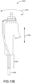
- first movable element 1036 when the medical apparatus is precisely positioned, tension on first movable element 1036 is relaxed, allowing second movable element 1038 to expand. As second movable element 1038 expands, the stent is allowed to further expand in the direction 1040, engaging the anchors or barbs 1030 into a vessel wall.
- the second constraining sheath 1022 can be released, allowing the second long leg to self expand.
- first movable element 1036 can be tensioned, allowing first movable element 1036 to be un-looped from second movable element 1038.
- First movable element 1036 can then be withdrawn through the tube 1028.
- the expanded stent graft is now unattached from the catheter assembly, allowing withdrawal 1042 of the catheter assembly.
Landscapes
- Health & Medical Sciences (AREA)
- Engineering & Computer Science (AREA)
- Biomedical Technology (AREA)
- Cardiology (AREA)
- Oral & Maxillofacial Surgery (AREA)
- Transplantation (AREA)
- Heart & Thoracic Surgery (AREA)
- Vascular Medicine (AREA)
- Life Sciences & Earth Sciences (AREA)
- Animal Behavior & Ethology (AREA)
- General Health & Medical Sciences (AREA)
- Public Health (AREA)
- Veterinary Medicine (AREA)
- Prostheses (AREA)
- Media Introduction/Drainage Providing Device (AREA)
- Gastroenterology & Hepatology (AREA)
- Pulmonology (AREA)
Priority Applications (1)
| Application Number | Priority Date | Filing Date | Title |
|---|---|---|---|
| EP24199486.2A EP4497420A3 (en) | 2008-06-04 | 2009-06-04 | Controlled deployable medical device |
Applications Claiming Priority (3)
| Application Number | Priority Date | Filing Date | Title |
|---|---|---|---|
| US5877608P | 2008-06-04 | 2008-06-04 | |
| EP09758758.8A EP2323595B1 (en) | 2008-06-04 | 2009-06-04 | Controlled deployable medical device |
| PCT/US2009/003383 WO2009148594A1 (en) | 2008-06-04 | 2009-06-04 | Controlled deployable medical device and method of making the same |
Related Parent Applications (2)
| Application Number | Title | Priority Date | Filing Date |
|---|---|---|---|
| EP09758758.8A Division EP2323595B1 (en) | 2008-06-04 | 2009-06-04 | Controlled deployable medical device |
| EP09758758.8A Division-Into EP2323595B1 (en) | 2008-06-04 | 2009-06-04 | Controlled deployable medical device |
Related Child Applications (1)
| Application Number | Title | Priority Date | Filing Date |
|---|---|---|---|
| EP24199486.2A Division EP4497420A3 (en) | 2008-06-04 | 2009-06-04 | Controlled deployable medical device |
Publications (4)
| Publication Number | Publication Date |
|---|---|
| EP3566680A2 EP3566680A2 (en) | 2019-11-13 |
| EP3566680A3 EP3566680A3 (en) | 2020-02-26 |
| EP3566680C0 EP3566680C0 (en) | 2024-10-02 |
| EP3566680B1 true EP3566680B1 (en) | 2024-10-02 |
Family
ID=40983305
Family Applications (3)
| Application Number | Title | Priority Date | Filing Date |
|---|---|---|---|
| EP19181564.6A Active EP3566680B1 (en) | 2008-06-04 | 2009-06-04 | Controlled deployable medical device |
| EP24199486.2A Pending EP4497420A3 (en) | 2008-06-04 | 2009-06-04 | Controlled deployable medical device |
| EP09758758.8A Active EP2323595B1 (en) | 2008-06-04 | 2009-06-04 | Controlled deployable medical device |
Family Applications After (2)
| Application Number | Title | Priority Date | Filing Date |
|---|---|---|---|
| EP24199486.2A Pending EP4497420A3 (en) | 2008-06-04 | 2009-06-04 | Controlled deployable medical device |
| EP09758758.8A Active EP2323595B1 (en) | 2008-06-04 | 2009-06-04 | Controlled deployable medical device |
Country Status (7)
| Country | Link |
|---|---|
| US (4) | US20100049294A1 (cg-RX-API-DMAC7.html) |
| EP (3) | EP3566680B1 (cg-RX-API-DMAC7.html) |
| JP (2) | JP5536763B2 (cg-RX-API-DMAC7.html) |
| AU (1) | AU2009255600B2 (cg-RX-API-DMAC7.html) |
| CA (2) | CA2835521C (cg-RX-API-DMAC7.html) |
| ES (2) | ES2998234T3 (cg-RX-API-DMAC7.html) |
| WO (1) | WO2009148594A1 (cg-RX-API-DMAC7.html) |
Families Citing this family (115)
| Publication number | Priority date | Publication date | Assignee | Title |
|---|---|---|---|---|
| US6306166B1 (en) * | 1997-08-13 | 2001-10-23 | Scimed Life Systems, Inc. | Loading and release of water-insoluble drugs |
| US20100063585A1 (en) * | 2006-07-03 | 2010-03-11 | Hemoteq Ag | Manufacture, method and use of active substance-releasing medical products for permanently keeping blood vessels open |
| ES2409759T3 (es) * | 2007-01-21 | 2013-06-27 | Hemoteq Ag | Producto médico para el tratamiento de la estenosis de los canales del cuerpo y para la prevención de la estenosis amenazante |
| US9192697B2 (en) * | 2007-07-03 | 2015-11-24 | Hemoteq Ag | Balloon catheter for treating stenosis of body passages and for preventing threatening restenosis |
| CA2835521C (en) | 2008-06-04 | 2016-04-19 | Gore Enterprise Holdings, Inc. | Controlled deployable medical device and method of making the same |
| ES2993912T3 (en) | 2008-06-04 | 2025-01-13 | Gore & Ass | Controlled deployable medical device and method of making the same |
| US8769796B2 (en) | 2008-09-25 | 2014-07-08 | Advanced Bifurcation Systems, Inc. | Selective stent crimping |
| US12324756B2 (en) | 2008-09-25 | 2025-06-10 | Advanced Bifurcation Systems Inc. | System and methods for treating a bifurcation |
| US12076258B2 (en) | 2008-09-25 | 2024-09-03 | Advanced Bifurcation Systems Inc. | Selective stent crimping |
| US11298252B2 (en) | 2008-09-25 | 2022-04-12 | Advanced Bifurcation Systems Inc. | Stent alignment during treatment of a bifurcation |
| US8979917B2 (en) | 2008-09-25 | 2015-03-17 | Advanced Bifurcation Systems, Inc. | System and methods for treating a bifurcation |
| WO2010036982A1 (en) | 2008-09-25 | 2010-04-01 | Henry Bourang | Partially crimped stent |
| US8858610B2 (en) | 2009-01-19 | 2014-10-14 | W. L. Gore & Associates, Inc. | Forced deployment sequence |
| EP3064230B1 (en) | 2009-07-10 | 2019-04-10 | Boston Scientific Scimed, Inc. | Use of nanocrystals for a drug delivery balloon |
| JP5933434B2 (ja) | 2009-07-17 | 2016-06-08 | ボストン サイエンティフィック サイムド,インコーポレイテッドBoston Scientific Scimed,Inc. | 薬剤送達バルーンの製造方法 |
| CN103037815B (zh) | 2010-03-24 | 2015-05-13 | 高级分支系统股份有限公司 | 通过临时张开侧分支来处理分叉部的方法和系统 |
| AU2011232361B2 (en) | 2010-03-24 | 2015-05-28 | Advanced Bifurcation Systems Inc. | Stent alignment during treatment of a bifurcation |
| CA2747610C (en) * | 2010-08-13 | 2014-09-16 | Cook Medical Technologies Llc | Precannulated fenestration |
| US8889211B2 (en) | 2010-09-02 | 2014-11-18 | Boston Scientific Scimed, Inc. | Coating process for drug delivery balloons using heat-induced rewrap memory |
| US20130274858A1 (en) * | 2010-12-19 | 2013-10-17 | Inspiremd Ltd | Stent with sheath and metal wire retainer |
| WO2012109365A1 (en) | 2011-02-08 | 2012-08-16 | Advanced Bifurcation Systems, Inc. | System and methods for treating a bifurcation with a fully crimped stent |
| CA2826760A1 (en) | 2011-02-08 | 2012-08-16 | Advanced Bifurcation Systems, Inc. | Multi-stent and multi-balloon apparatus for treating bifurcations and methods of use |
| US9744033B2 (en) | 2011-04-01 | 2017-08-29 | W.L. Gore & Associates, Inc. | Elastomeric leaflet for prosthetic heart valves |
| GB201106017D0 (en) * | 2011-04-08 | 2011-05-25 | Lombard Medical Plc | Apparatus for deploying a stent graft |
| US10117765B2 (en) | 2011-06-14 | 2018-11-06 | W.L. Gore Associates, Inc | Apposition fiber for use in endoluminal deployment of expandable implants |
| WO2013022458A1 (en) | 2011-08-05 | 2013-02-14 | Boston Scientific Scimed, Inc. | Methods of converting amorphous drug substance into crystalline form |
| US9314328B2 (en) | 2011-08-16 | 2016-04-19 | W. L. Gore & Associates, Inc. | Branched stent graft device and deployment |
| WO2013028208A1 (en) | 2011-08-25 | 2013-02-28 | Boston Scientific Scimed, Inc. | Medical device with crystalline drug coating |
| US9554806B2 (en) | 2011-09-16 | 2017-01-31 | W. L. Gore & Associates, Inc. | Occlusive devices |
| US9782282B2 (en) | 2011-11-14 | 2017-10-10 | W. L. Gore & Associates, Inc. | External steerable fiber for use in endoluminal deployment of expandable devices |
| US9877858B2 (en) | 2011-11-14 | 2018-01-30 | W. L. Gore & Associates, Inc. | External steerable fiber for use in endoluminal deployment of expandable devices |
| US9364359B2 (en) * | 2011-12-08 | 2016-06-14 | W. L. Gore & Associates, Inc. | Systems and methods for delivery of a medical device |
| US9375308B2 (en) | 2012-03-13 | 2016-06-28 | W. L. Gore & Associates, Inc. | External steerable fiber for use in endoluminal deployment of expandable devices |
| US8968384B2 (en) * | 2012-04-27 | 2015-03-03 | Medtronic Vascular, Inc. | Circumferentially constraining sutures for a stent-graft |
| US9283072B2 (en) | 2012-07-25 | 2016-03-15 | W. L. Gore & Associates, Inc. | Everting transcatheter valve and methods |
| US10376360B2 (en) | 2012-07-27 | 2019-08-13 | W. L. Gore & Associates, Inc. | Multi-frame prosthetic valve apparatus and methods |
| US10039638B2 (en) | 2012-12-19 | 2018-08-07 | W. L. Gore & Associates, Inc. | Geometric prosthetic heart valves |
| US10321986B2 (en) | 2012-12-19 | 2019-06-18 | W. L. Gore & Associates, Inc. | Multi-frame prosthetic heart valve |
| US10966820B2 (en) | 2012-12-19 | 2021-04-06 | W. L. Gore & Associates, Inc. | Geometric control of bending character in prosthetic heart valve leaflets |
| US9101469B2 (en) | 2012-12-19 | 2015-08-11 | W. L. Gore & Associates, Inc. | Prosthetic heart valve with leaflet shelving |
| US9968443B2 (en) | 2012-12-19 | 2018-05-15 | W. L. Gore & Associates, Inc. | Vertical coaptation zone in a planar portion of prosthetic heart valve leaflet |
| US9144492B2 (en) | 2012-12-19 | 2015-09-29 | W. L. Gore & Associates, Inc. | Truncated leaflet for prosthetic heart valves, preformed valve |
| US9737398B2 (en) | 2012-12-19 | 2017-08-22 | W. L. Gore & Associates, Inc. | Prosthetic valves, frames and leaflets and methods thereof |
| US9622893B2 (en) * | 2012-12-20 | 2017-04-18 | Cook Medical Technologies Llc | Apparatus and method for improved deployment of endovascular grafts |
| US9987155B1 (en) | 2013-03-07 | 2018-06-05 | W. L. Gore & Associates, Inc. | Implantable medical devices and related delivery systems |
| US20160120676A1 (en) * | 2013-05-13 | 2016-05-05 | Inside Medical Industria E Comercio de Produtos Medicios Hospitalares LTDA | Mechanism for Guiding and or Releasing of an Endoprosthesis with Injured Regions of a Blood Vessel, Applied in Catheter-Like Medical Device |
| US11911258B2 (en) | 2013-06-26 | 2024-02-27 | W. L. Gore & Associates, Inc. | Space filling devices |
| US10610386B2 (en) | 2014-06-27 | 2020-04-07 | Boston Scientific Scimed, Inc. | Compositions, devices, kits and methods for attaching stent-containing medical devices to tissue |
| US9993332B2 (en) | 2014-07-09 | 2018-06-12 | Medos International Sarl | Systems and methods for ligament graft preparation |
| US10314697B2 (en) | 2014-08-18 | 2019-06-11 | W. L. Gore & Associates, Inc. | Frame with integral sewing cuff for prosthetic valves |
| US9827094B2 (en) | 2014-09-15 | 2017-11-28 | W. L. Gore & Associates, Inc. | Prosthetic heart valve with retention elements |
| US10182808B2 (en) | 2015-04-23 | 2019-01-22 | DePuy Synthes Products, Inc. | Knotless suture anchor guide |
| US11129622B2 (en) | 2015-05-14 | 2021-09-28 | W. L. Gore & Associates, Inc. | Devices and methods for occlusion of an atrial appendage |
| US10383720B2 (en) | 2015-12-22 | 2019-08-20 | DePuy Synthes Products, Inc. | Graft preparation system |
| US10188538B2 (en) * | 2015-12-30 | 2019-01-29 | Cook Medical Technologies Llc | Hybrid trigger wire for endografts |
| US10420642B2 (en) * | 2016-03-14 | 2019-09-24 | Medtronic Vascular, Inc. | Transcatheter stented prosthetic heart valve delivery devices |
| EP3468505B1 (en) | 2016-06-13 | 2021-02-24 | Aortica Corporation | Systems and devices for marking and/or reinforcing fenestrations in prosthetic implants |
| CN113229998B (zh) | 2016-08-02 | 2025-03-25 | 波尔顿医疗公司 | 用于将假体植入物联接到开窗体的系统、装置和方法 |
| EP3493767B1 (en) | 2016-08-05 | 2020-11-11 | W. L. Gore & Associates, Inc. | Integrated medical device constraining lumen |
| US10744015B2 (en) | 2016-08-24 | 2020-08-18 | W. L. Gore & Associates, Inc. | Sleeves for expandable medical devices |
| CA3032020C (en) | 2016-09-09 | 2021-03-30 | W. L. Gore & Associates, Inc. | Total arch concept |
| EP3534838B1 (en) | 2017-02-24 | 2021-01-27 | Bolton Medical, Inc. | Radially adjustable stent graft delivery system |
| WO2018156848A1 (en) | 2017-02-24 | 2018-08-30 | Bolton Medical, Inc. | Vascular prosthesis with crimped adapter and methods of use |
| WO2018156850A1 (en) | 2017-02-24 | 2018-08-30 | Bolton Medical, Inc. | Stent graft with fenestration lock |
| EP3585320B2 (en) | 2017-02-24 | 2025-07-09 | Bolton Medical, Inc. | Delivery system for radially constricting a stent graft |
| WO2018156842A1 (en) | 2017-02-24 | 2018-08-30 | Bolton Medical, Inc. | System and method to radially constrict a stent graft |
| EP3534848B1 (en) | 2017-02-24 | 2023-06-28 | Bolton Medical, Inc. | Stent graft delivery system with constricted sheath |
| WO2018156840A1 (en) | 2017-02-24 | 2018-08-30 | Bolton Medical, Inc. | Constrainable stent graft, delivery system and methods of use |
| WO2018156847A1 (en) | 2017-02-24 | 2018-08-30 | Bolton Medical, Inc. | Delivery system and method to radially constrict a stent graft |
| WO2018156849A1 (en) | 2017-02-24 | 2018-08-30 | Bolton Medical, Inc. | Vascular prosthesis with fenestration ring and methods of use |
| WO2018156851A1 (en) | 2017-02-24 | 2018-08-30 | Bolton Medical, Inc. | Vascular prosthesis with moveable fenestration |
| JP6883115B2 (ja) * | 2017-03-08 | 2021-06-09 | ダブリュ.エル.ゴア アンド アソシエイツ,インコーポレイティドW.L. Gore & Associates, Incorporated | 角度付け用ステアリングワイヤーアタッチ |
| US10709541B2 (en) * | 2017-04-28 | 2020-07-14 | Cook Medical Technologies Llc | Systems and methods for adjusting the diameter of an endoluminal prosthesis and an endoluminal prosthesis configured for the same |
| CN110709030B (zh) | 2017-07-17 | 2022-09-27 | 美敦力瓦斯科尔勒公司 | 具有扭矩轴的带支架的假体递送装置 |
| US10959842B2 (en) | 2017-09-12 | 2021-03-30 | W. L. Gore & Associates, Inc. | Leaflet frame attachment for prosthetic valves |
| CN115813605A (zh) | 2017-09-25 | 2023-03-21 | 波尔顿医疗公司 | 用于将假体植入物联接到开窗体的系统、装置和方法 |
| AU2018342223B2 (en) | 2017-09-27 | 2021-04-01 | Edwards Lifesciences Corporation | Prosthetic valves with mechanically coupled leaflets |
| JP7068444B2 (ja) | 2017-09-27 | 2022-05-16 | ダブリュ.エル.ゴア アンド アソシエイツ,インコーポレイティド | 拡張可能なフレームを備えた人工弁、並びに関連するシステム及び方法 |
| JP7036912B2 (ja) | 2017-10-13 | 2022-03-15 | ダブリュ.エル.ゴア アンド アソシエイツ,インコーポレイティド | 嵌込式人工弁および送達システム |
| US11173023B2 (en) | 2017-10-16 | 2021-11-16 | W. L. Gore & Associates, Inc. | Medical devices and anchors therefor |
| US11154397B2 (en) | 2017-10-31 | 2021-10-26 | W. L. Gore & Associates, Inc. | Jacket for surgical heart valve |
| CN114831777A (zh) | 2017-10-31 | 2022-08-02 | W.L.戈尔及同仁股份有限公司 | 假体心脏瓣膜 |
| CA3078473C (en) | 2017-10-31 | 2023-03-14 | W. L. Gore & Associates, Inc. | Transcatheter deployment systems and associated methods |
| JP7052032B2 (ja) | 2017-10-31 | 2022-04-11 | ダブリュ.エル.ゴア アンド アソシエイツ,インコーポレイティド | 組織内方成長を促進する医療用弁及び弁膜 |
| ES2910187T3 (es) | 2017-10-31 | 2022-05-11 | Bolton Medical Inc | Componente de torque distal, sistema de colocación y método de uso del mismo |
| US11786387B2 (en) | 2017-11-24 | 2023-10-17 | Ptmc Institute | Stent graft transport device |
| WO2019195860A2 (en) | 2018-04-04 | 2019-10-10 | Vdyne, Llc | Devices and methods for anchoring transcatheter heart valve |
| JP7569219B2 (ja) | 2018-05-31 | 2024-10-17 | エンドロジックス リミテッド ライアビリティ カンパニー | チャネル内の拘束を有するステントグラフトシステム及びその方法 |
| KR102753787B1 (ko) * | 2018-06-04 | 2025-01-10 | 보스톤 싸이엔티픽 싸이메드 인코포레이티드 | 제거 가능한 스텐트 |
| AU2018439076B2 (en) | 2018-08-31 | 2022-07-07 | W. L. Gore & Associates, Inc. | Apparatus, system, and method for steering an implantable medical device |
| US12186187B2 (en) | 2018-09-20 | 2025-01-07 | Vdyne, Inc. | Transcatheter deliverable prosthetic heart valves and methods of delivery |
| US10321995B1 (en) | 2018-09-20 | 2019-06-18 | Vdyne, Llc | Orthogonally delivered transcatheter heart valve replacement |
| US11071627B2 (en) | 2018-10-18 | 2021-07-27 | Vdyne, Inc. | Orthogonally delivered transcatheter heart valve frame for valve in valve prosthesis |
| US11278437B2 (en) | 2018-12-08 | 2022-03-22 | Vdyne, Inc. | Compression capable annular frames for side delivery of transcatheter heart valve replacement |
| US11344413B2 (en) | 2018-09-20 | 2022-05-31 | Vdyne, Inc. | Transcatheter deliverable prosthetic heart valves and methods of delivery |
| US12310850B2 (en) | 2018-09-20 | 2025-05-27 | Vdyne, Inc. | Transcatheter deliverable prosthetic heart valves and methods of delivery |
| US11109969B2 (en) * | 2018-10-22 | 2021-09-07 | Vdyne, Inc. | Guidewire delivery of transcatheter heart valve |
| USD926322S1 (en) | 2018-11-07 | 2021-07-27 | W. L. Gore & Associates, Inc. | Heart valve cover |
| US11253359B2 (en) | 2018-12-20 | 2022-02-22 | Vdyne, Inc. | Proximal tab for side-delivered transcatheter heart valves and methods of delivery |
| WO2020146842A1 (en) | 2019-01-10 | 2020-07-16 | Vdyne, Llc | Anchor hook for side-delivery transcatheter heart valve prosthesis |
| US11185409B2 (en) | 2019-01-26 | 2021-11-30 | Vdyne, Inc. | Collapsible inner flow control component for side-delivered transcatheter heart valve prosthesis |
| US11273032B2 (en) | 2019-01-26 | 2022-03-15 | Vdyne, Inc. | Collapsible inner flow control component for side-deliverable transcatheter heart valve prosthesis |
| US11497601B2 (en) | 2019-03-01 | 2022-11-15 | W. L. Gore & Associates, Inc. | Telescoping prosthetic valve with retention element |
| CA3132162A1 (en) | 2019-03-05 | 2020-09-10 | Vdyne, Inc. | Tricuspid regurgitation control devices for orthogonal transcatheter heart valve prosthesis |
| US20220151807A1 (en) * | 2019-03-06 | 2022-05-19 | Kawasumi Laboratories, Inc. | Stent |
| US11173027B2 (en) | 2019-03-14 | 2021-11-16 | Vdyne, Inc. | Side-deliverable transcatheter prosthetic valves and methods for delivering and anchoring the same |
| US11076956B2 (en) | 2019-03-14 | 2021-08-03 | Vdyne, Inc. | Proximal, distal, and anterior anchoring tabs for side-delivered transcatheter mitral valve prosthesis |
| CA3131177C (en) | 2019-04-12 | 2024-02-13 | W.L. Gore & Associates, Inc. | Valve with multi-part frame and associated resilient bridging features |
| CN120827457A (zh) | 2019-05-04 | 2025-10-24 | 维迪内股份有限公司 | 用于在自体瓣环中部署侧面递送的假体心脏瓣膜的束紧装置和方法 |
| CN114599316B (zh) | 2019-08-20 | 2025-09-30 | 维迪内股份有限公司 | 用于可侧面递送经导管人工瓣膜的递送和取回装置和方法 |
| WO2021040996A1 (en) | 2019-08-26 | 2021-03-04 | Vdyne, Inc. | Side-deliverable transcatheter prosthetic valves and methods for delivering and anchoring the same |
| US11234813B2 (en) | 2020-01-17 | 2022-02-01 | Vdyne, Inc. | Ventricular stability elements for side-deliverable prosthetic heart valves and methods of delivery |
| AU2021224755A1 (en) * | 2020-02-20 | 2022-08-18 | Major Medical Devices LLC | Systems and methods for introducing a stent-graft through a blood vessel located above a diaphragm |
| AU2021201336B1 (en) | 2021-03-02 | 2021-07-15 | Cook Medical Technologies Llc | A constraint arrangement for a stent-graft loaded onto a delivery system |
| CN115024858B (zh) * | 2022-08-11 | 2022-11-04 | 上海微创心脉医疗科技(集团)股份有限公司 | 输送装置和支架系统 |
Citations (1)
| Publication number | Priority date | Publication date | Assignee | Title |
|---|---|---|---|---|
| EP2262444B1 (en) * | 2008-04-09 | 2018-02-28 | Cook Medical Technologies LLC | Stent-graft |
Family Cites Families (104)
| Publication number | Priority date | Publication date | Assignee | Title |
|---|---|---|---|---|
| US5693083A (en) * | 1983-12-09 | 1997-12-02 | Endovascular Technologies, Inc. | Thoracic graft and delivery catheter |
| US4738666A (en) * | 1985-06-11 | 1988-04-19 | Genus Catheter Technologies, Inc. | Variable diameter catheter |
| US5035706A (en) | 1989-10-17 | 1991-07-30 | Cook Incorporated | Percutaneous stent and method for retrieval thereof |
| US5387235A (en) * | 1991-10-25 | 1995-02-07 | Cook Incorporated | Expandable transluminal graft prosthesis for repair of aneurysm |
| US5405378A (en) * | 1992-05-20 | 1995-04-11 | Strecker; Ernst P. | Device with a prosthesis implantable in the body of a patient |
| EP0681456A4 (en) * | 1993-01-27 | 1996-08-07 | Instent Inc | VASCULAR AND CORONARY EXTENDERS. |
| US5480423A (en) * | 1993-05-20 | 1996-01-02 | Boston Scientific Corporation | Prosthesis delivery |
| US5464449A (en) * | 1993-07-08 | 1995-11-07 | Thomas J. Fogarty | Internal graft prosthesis and delivery system |
| IT1269443B (it) * | 1994-01-19 | 1997-04-01 | Stefano Nazari | Protesi vascolare per la sostituzione o il rivestimento interno di vasi sanguigni di medio e grande diametro e dispositivo per la sua applicazione senza interruzione del flusso ematico |
| US5683451A (en) * | 1994-06-08 | 1997-11-04 | Cardiovascular Concepts, Inc. | Apparatus and methods for deployment release of intraluminal prostheses |
| US5800521A (en) * | 1994-11-09 | 1998-09-01 | Endotex Interventional Systems, Inc. | Prosthetic graft and method for aneurysm repair |
| US5609628A (en) * | 1995-04-20 | 1997-03-11 | Keranen; Victor J. | Intravascular graft and catheter |
| WO1996036297A1 (en) * | 1995-05-19 | 1996-11-21 | Kanji Inoue | Transplantation instrument, method of bending same and method of transplanting same |
| US6270520B1 (en) * | 1995-05-19 | 2001-08-07 | Kanji Inoue | Appliance to be implanted, method of collapsing the appliance to be implanted and method of using the appliance to be implanted |
| US5713948A (en) * | 1995-07-19 | 1998-02-03 | Uflacker; Renan | Adjustable and retrievable graft and graft delivery system for stent-graft system |
| IT1279628B1 (it) * | 1995-09-13 | 1997-12-16 | Xtrode Srl | Dispositivo e metodo per il montaggio di una endoprotesi vascolare su un catetere provvisto di un pallone espandibile |
| US6287315B1 (en) * | 1995-10-30 | 2001-09-11 | World Medical Manufacturing Corporation | Apparatus for delivering an endoluminal prosthesis |
| US6042605A (en) | 1995-12-14 | 2000-03-28 | Gore Enterprose Holdings, Inc. | Kink resistant stent-graft |
| US5843158A (en) * | 1996-01-05 | 1998-12-01 | Medtronic, Inc. | Limited expansion endoluminal prostheses and methods for their use |
| US5643279A (en) * | 1996-03-12 | 1997-07-01 | Cordis Corporation | Method of catheter balloon manufacture and use |
| ATE288233T1 (de) * | 1996-06-20 | 2005-02-15 | Vascutek Ltd | Reparieren von körpergefässen durch prothesen |
| US6551350B1 (en) | 1996-12-23 | 2003-04-22 | Gore Enterprise Holdings, Inc. | Kink resistant bifurcated prosthesis |
| US6352561B1 (en) | 1996-12-23 | 2002-03-05 | W. L. Gore & Associates | Implant deployment apparatus |
| US6090128A (en) * | 1997-02-20 | 2000-07-18 | Endologix, Inc. | Bifurcated vascular graft deployment device |
| US5824055A (en) * | 1997-03-25 | 1998-10-20 | Endotex Interventional Systems, Inc. | Stent graft delivery system and methods of use |
| US5957929A (en) * | 1997-05-02 | 1999-09-28 | Micro Therapeutics, Inc. | Expandable stent apparatus and method |
| FR2762989B1 (fr) * | 1997-05-12 | 1999-09-03 | Braun Celsa Sa | Systeme de reparation d'un conduit anatomique par un implant a ouverture progressive |
| US6168616B1 (en) * | 1997-06-02 | 2001-01-02 | Global Vascular Concepts | Manually expandable stent |
| US20070010875A1 (en) * | 1997-06-30 | 2007-01-11 | Trout Hugh H | Method and apparatus to attach an unsupported surgical component |
| US6070589A (en) * | 1997-08-01 | 2000-06-06 | Teramed, Inc. | Methods for deploying bypass graft stents |
| US6235051B1 (en) * | 1997-12-16 | 2001-05-22 | Timothy P. Murphy | Method of stent-graft system delivery |
| US5910144A (en) * | 1998-01-09 | 1999-06-08 | Endovascular Technologies, Inc. | Prosthesis gripping system and method |
| US6776791B1 (en) * | 1998-04-01 | 2004-08-17 | Endovascular Technologies, Inc. | Stent and method and device for packing of same |
| US6537284B1 (en) * | 1998-10-29 | 2003-03-25 | Kanji Inoue | Device for guiding an appliance |
| US6855159B1 (en) * | 1999-02-05 | 2005-02-15 | Eva Corporation | Surgical guide line assembly and separator assembly for use during a surgical procedure |
| US6261316B1 (en) * | 1999-03-11 | 2001-07-17 | Endologix, Inc. | Single puncture bifurcation graft deployment system |
| EP1095635A4 (en) * | 1999-05-06 | 2007-06-20 | Kanji Inoue | INSTRUMENTAL BANDER APPARATUS AND USE OF THE APPARATUS |
| US6398802B1 (en) * | 1999-06-21 | 2002-06-04 | Scimed Life Systems, Inc. | Low profile delivery system for stent and graft deployment |
| DE60006348T2 (de) * | 1999-07-16 | 2004-12-02 | Med Institute, Inc., West Lafayette | Stent zur verhedderfreien entfaltung |
| US6183481B1 (en) * | 1999-09-22 | 2001-02-06 | Endomed Inc. | Delivery system for self-expanding stents and grafts |
| US7074235B1 (en) | 1999-10-16 | 2006-07-11 | Sumit Roy | Low-profile, non-stented prosthesis for transluminal implantation |
| JP2003522591A (ja) * | 2000-02-15 | 2003-07-29 | イーバ コーポレイション | 外科処置で使用するための一時的ステント組立体 |
| DK1263349T3 (da) * | 2000-03-14 | 2009-10-19 | Cook Inc | Endovaskulær stentgraft |
| US6899727B2 (en) * | 2001-01-22 | 2005-05-31 | Gore Enterprise Holdings, Inc. | Deployment system for intraluminal devices |
| US20040138734A1 (en) * | 2001-04-11 | 2004-07-15 | Trivascular, Inc. | Delivery system and method for bifurcated graft |
| US6733521B2 (en) | 2001-04-11 | 2004-05-11 | Trivascular, Inc. | Delivery system and method for endovascular graft |
| US6761733B2 (en) * | 2001-04-11 | 2004-07-13 | Trivascular, Inc. | Delivery system and method for bifurcated endovascular graft |
| US6837901B2 (en) * | 2001-04-27 | 2005-01-04 | Intek Technology L.L.C. | Methods for delivering, repositioning and/or retrieving self-expanding stents |
| US6821291B2 (en) * | 2001-06-01 | 2004-11-23 | Ams Research Corporation | Retrievable stent and method of use thereof |
| US7147657B2 (en) * | 2003-10-23 | 2006-12-12 | Aptus Endosystems, Inc. | Prosthesis delivery systems and methods |
| US6723116B2 (en) * | 2002-01-14 | 2004-04-20 | Syde A. Taheri | Exclusion of ascending/descending aorta and/or aortic arch aneurysm |
| US20030135269A1 (en) * | 2002-01-16 | 2003-07-17 | Swanstrom Lee L. | Laparoscopic-assisted endovascular/endoluminal graft placement |
| EP1469794B1 (en) * | 2002-01-28 | 2009-03-18 | OrbusNeich Medical, Inc. | Flared ostial endoprosthesis and delivery system |
| US6911039B2 (en) * | 2002-04-23 | 2005-06-28 | Medtronic Vascular, Inc. | Integrated mechanical handle with quick slide mechanism |
| ATE310559T1 (de) | 2002-05-29 | 2005-12-15 | Cook William A Australia | Trigger-draht system für eine prothesenplazierungsvorrichtung |
| WO2003101346A1 (en) * | 2002-05-29 | 2003-12-11 | William A. Cook Australia Pty. Ltd. | Multi-piece prosthesis deployment apparatus |
| US7264632B2 (en) * | 2002-06-07 | 2007-09-04 | Medtronic Vascular, Inc. | Controlled deployment delivery system |
| US8518096B2 (en) * | 2002-09-03 | 2013-08-27 | Lifeshield Sciences Llc | Elephant trunk thoracic endograft and delivery system |
| US7169172B2 (en) * | 2002-11-01 | 2007-01-30 | Counter Clockwise, Inc. | Method and apparatus for caged stent delivery |
| AU2003291541A1 (en) * | 2002-11-15 | 2004-06-15 | Paracor Medical, Inc. | Cardiac harness delivery device |
| DE03790040T1 (de) * | 2002-11-26 | 2007-01-04 | Endologix, Inc., Irvine | Implantat-ablagesystem |
| US20040106199A1 (en) * | 2002-12-02 | 2004-06-03 | Eliseev Alexey V. | Charged cyclodextrin derivatives and their use in plant cell and tissue culture growth media |
| US7763062B2 (en) * | 2003-01-21 | 2010-07-27 | Boston Scientific Scimed, Inc. | Method and system for delivering and implanting a graft |
| WO2004078065A2 (en) * | 2003-03-03 | 2004-09-16 | Sinus Rhythm Technologies, Inc. | Electrical conduction block implant device |
| US6984244B2 (en) * | 2003-03-27 | 2006-01-10 | Endovascular Technologies, Inc. | Delivery system for endoluminal implant |
| CA2518890C (en) * | 2003-04-03 | 2012-06-05 | William A. Cook Australia Pty. Ltd. | Branch stent graft deployment and method |
| US7226473B2 (en) * | 2003-05-23 | 2007-06-05 | Brar Balbir S | Treatment of stenotic regions |
| US6945990B2 (en) * | 2003-08-16 | 2005-09-20 | Medtronic Vascular, Inc. | Double sheath deployment system |
| US8292943B2 (en) * | 2003-09-03 | 2012-10-23 | Bolton Medical, Inc. | Stent graft with longitudinal support member |
| US7651519B2 (en) * | 2003-09-16 | 2010-01-26 | Cook Incorporated | Prosthesis deployment system |
| CA2541807C (en) * | 2003-10-10 | 2012-07-10 | William Cook Europe Aps | Stent graft retention system |
| EP3031426B1 (en) * | 2003-10-14 | 2022-07-20 | Cook Medical Technologies LLC | Introducer for an iliac side branch device |
| ATE464864T1 (de) * | 2003-10-15 | 2010-05-15 | Cook Inc | Haltevorrichtung für ein prothesenablagesystem |
| FR2863160B1 (fr) * | 2003-12-09 | 2006-03-03 | Perouse Laboratoires | Dispositif de traitement d'un vaisseau sanguin et procede de preparation de ce dispositif |
| JP2005179587A (ja) | 2003-12-22 | 2005-07-07 | Jsr Corp | 膜形成用組成物、膜の形成方法およびシリカ系膜 |
| FR2865926B1 (fr) | 2004-02-11 | 2006-05-12 | Perouse Laboratoires | Prothese tubulaire. |
| WO2006007389A1 (en) * | 2004-06-16 | 2006-01-19 | Cook Incorprated | Thoracic deployment device and stent graft |
| CA2568733A1 (en) | 2004-06-28 | 2006-01-12 | Xtent, Inc. | Devices and methods for controlling expandable prostheses during deployment |
| WO2006037086A1 (en) | 2004-09-28 | 2006-04-06 | William A. Cook Australia Pty. Ltd. | Device for treating aortic dissection |
| EP1827304B1 (en) * | 2004-10-25 | 2011-04-20 | Merit Medical Systems, Inc. | Stent removal and repositioning device |
| US8287583B2 (en) * | 2005-01-10 | 2012-10-16 | Taheri Laduca Llc | Apparatus and method for deploying an implantable device within the body |
| EP1850791B1 (en) * | 2005-01-28 | 2017-08-16 | Boston Scientific Limited | Stent retrieval member and devices for retrieving or repositioning a stent |
| US7918880B2 (en) * | 2005-02-16 | 2011-04-05 | Boston Scientific Scimed, Inc. | Self-expanding stent and delivery system |
| US20060229699A1 (en) * | 2005-04-12 | 2006-10-12 | Tehrani Nasser S | Stent-stabilizing device |
| EP1877012B1 (en) * | 2005-05-04 | 2017-04-26 | Cook Medical Technologies LLC | Expandable and retrievable stent |
| FR2887139B1 (fr) | 2005-06-15 | 2008-04-25 | Perouse Soc Par Actions Simpli | Dispositif de traitement d'un vaisseau sanguin. |
| US8118852B2 (en) * | 2005-07-13 | 2012-02-21 | Cook Medical Technologies Llc | Introducer for self-expandable medical device |
| EP2497444B1 (en) * | 2005-08-18 | 2015-09-16 | Cook Medical Technologies LLC | Design and assembly of fenestrated stent grafts |
| US20070050015A1 (en) | 2005-08-25 | 2007-03-01 | Scimed Life Systems, Inc. | Endoluminal prosthesis adapted to deployment in a distorted branched body lumen and method of deploying the same |
| US8864808B2 (en) * | 2005-09-21 | 2014-10-21 | The Cleveland Clinic Foundation | Endoluminal delivery assembly |
| US20090048656A1 (en) | 2005-11-09 | 2009-02-19 | Ning Wen | Delivery Device for Delivering a Self-Expanding Stent |
| FR2894131B1 (fr) * | 2005-12-02 | 2008-12-05 | Perouse Soc Par Actions Simpli | Dispositif de traitement d'un vaisseau sanguin, et necessaire de traitement associe. |
| FR2896405B1 (fr) | 2006-01-24 | 2008-04-18 | Perouse Soc Par Actions Simpli | Dispositif de traitement d'un conduit de circulation du sang et procede de preparation associe |
| EP2583640B1 (en) * | 2006-02-16 | 2022-06-22 | Venus MedTech (HangZhou), Inc. | Minimally invasive replacement heart valve |
| US20070225797A1 (en) | 2006-03-24 | 2007-09-27 | Medtronic Vascular, Inc. | Prosthesis With Adjustable Opening for Side Branch Access |
| FR2899096B1 (fr) * | 2006-04-04 | 2008-12-05 | Perouse Soc Par Actions Simpli | Dispositif de traitement d'un conduit de circulation du sang et procede de preparation de ce dispositif |
| JP2010504820A (ja) | 2006-09-28 | 2010-02-18 | クック・インコーポレイテッド | 胸部大動脈瘤を修復するための装置および方法 |
| US7655034B2 (en) * | 2006-11-14 | 2010-02-02 | Medtronic Vascular, Inc. | Stent-graft with anchoring pins |
| CA2835521C (en) | 2008-06-04 | 2016-04-19 | Gore Enterprise Holdings, Inc. | Controlled deployable medical device and method of making the same |
| ES2993912T3 (en) | 2008-06-04 | 2025-01-13 | Gore & Ass | Controlled deployable medical device and method of making the same |
| GB0906065D0 (en) | 2009-04-07 | 2009-05-20 | Angiomed Ag | Delivery system for a prosthesis |
| US9198787B2 (en) | 2010-12-31 | 2015-12-01 | Cook Medical Technologies Llc | Conformable prosthesis delivery system and method for deployment thereof |
| US9375308B2 (en) | 2012-03-13 | 2016-06-28 | W. L. Gore & Associates, Inc. | External steerable fiber for use in endoluminal deployment of expandable devices |
| WO2014179763A1 (en) | 2013-05-03 | 2014-11-06 | Medtronic Inc. | Valve delivery tool |
-
2009
- 2009-06-04 CA CA2835521A patent/CA2835521C/en active Active
- 2009-06-04 EP EP19181564.6A patent/EP3566680B1/en active Active
- 2009-06-04 ES ES19181564T patent/ES2998234T3/es active Active
- 2009-06-04 US US12/478,331 patent/US20100049294A1/en not_active Abandoned
- 2009-06-04 AU AU2009255600A patent/AU2009255600B2/en active Active
- 2009-06-04 ES ES09758758T patent/ES2750335T3/es active Active
- 2009-06-04 CA CA2727000A patent/CA2727000C/en active Active
- 2009-06-04 WO PCT/US2009/003383 patent/WO2009148594A1/en not_active Ceased
- 2009-06-04 EP EP24199486.2A patent/EP4497420A3/en active Pending
- 2009-06-04 EP EP09758758.8A patent/EP2323595B1/en active Active
- 2009-06-04 JP JP2011512472A patent/JP5536763B2/ja active Active
-
2014
- 2014-01-06 JP JP2014000621A patent/JP6285719B2/ja active Active
- 2014-03-13 US US14/208,441 patent/US10219925B2/en active Active
-
2019
- 2019-03-04 US US16/291,188 patent/US11628079B2/en active Active
-
2023
- 2023-03-16 US US18/122,461 patent/US20230240872A1/en active Pending
Patent Citations (1)
| Publication number | Priority date | Publication date | Assignee | Title |
|---|---|---|---|---|
| EP2262444B1 (en) * | 2008-04-09 | 2018-02-28 | Cook Medical Technologies LLC | Stent-graft |
Also Published As
| Publication number | Publication date |
|---|---|
| JP2014111146A (ja) | 2014-06-19 |
| WO2009148594A1 (en) | 2009-12-10 |
| AU2009255600A1 (en) | 2009-12-10 |
| CA2727000C (en) | 2014-01-07 |
| CA2835521C (en) | 2016-04-19 |
| EP4497420A3 (en) | 2025-04-02 |
| ES2998234T3 (en) | 2025-02-19 |
| US11628079B2 (en) | 2023-04-18 |
| US20190192323A1 (en) | 2019-06-27 |
| EP3566680A3 (en) | 2020-02-26 |
| EP2323595B1 (en) | 2019-07-31 |
| CA2727000A1 (en) | 2009-12-10 |
| US20230240872A1 (en) | 2023-08-03 |
| EP4497420A2 (en) | 2025-01-29 |
| EP3566680C0 (en) | 2024-10-02 |
| JP6285719B2 (ja) | 2018-02-28 |
| CA2835521A1 (en) | 2009-12-10 |
| US20140194968A1 (en) | 2014-07-10 |
| US20100049294A1 (en) | 2010-02-25 |
| US10219925B2 (en) | 2019-03-05 |
| EP2323595A1 (en) | 2011-05-25 |
| AU2009255600B2 (en) | 2014-02-13 |
| ES2750335T3 (es) | 2020-03-25 |
| JP5536763B2 (ja) | 2014-07-02 |
| EP3566680A2 (en) | 2019-11-13 |
| JP2011522590A (ja) | 2011-08-04 |
Similar Documents
| Publication | Publication Date | Title |
|---|---|---|
| US20230240872A1 (en) | Controlled deployable medical device and method of making the same | |
| US10905576B2 (en) | Controlled deployable medical device and method of making the same | |
| EP3040054B1 (en) | Low profile prosthesis delivery device | |
| US20110251664A1 (en) | Short Legged Bifurcated Stent Graft Distal Capture Element and Method | |
| EP1355591A2 (en) | Deployment system for intraluminal devices | |
| CN102639086A (zh) | 包含固定架的血管假体组件及其方法 | |
| US20060136033A1 (en) | Coiled stent delivery system and method | |
| HK40015571A (en) | Controlled deployable medical device | |
| HK1153114B (en) | Controlled deployable medical device | |
| HK1153114A (en) | Controlled deployable medical device |
Legal Events
| Date | Code | Title | Description |
|---|---|---|---|
| PUAI | Public reference made under article 153(3) epc to a published international application that has entered the european phase |
Free format text: ORIGINAL CODE: 0009012 |
|
| STAA | Information on the status of an ep patent application or granted ep patent |
Free format text: STATUS: THE APPLICATION HAS BEEN PUBLISHED |
|
| AC | Divisional application: reference to earlier application |
Ref document number: 2323595 Country of ref document: EP Kind code of ref document: P |
|
| AK | Designated contracting states |
Kind code of ref document: A2 Designated state(s): AT BE BG CH CY CZ DE DK EE ES FI FR GB GR HR HU IE IS IT LI LT LU LV MC MK MT NL NO PL PT RO SE SI SK TR |
|
| PUAL | Search report despatched |
Free format text: ORIGINAL CODE: 0009013 |
|
| AK | Designated contracting states |
Kind code of ref document: A3 Designated state(s): AT BE BG CH CY CZ DE DK EE ES FI FR GB GR HR HU IE IS IT LI LT LU LV MC MK MT NL NO PL PT RO SE SI SK TR |
|
| RIC1 | Information provided on ipc code assigned before grant |
Ipc: A61F 2/95 20130101AFI20200121BHEP |
|
| STAA | Information on the status of an ep patent application or granted ep patent |
Free format text: STATUS: REQUEST FOR EXAMINATION WAS MADE |
|
| REG | Reference to a national code |
Ref country code: HK Ref legal event code: DE Ref document number: 40015571 Country of ref document: HK |
|
| 17P | Request for examination filed |
Effective date: 20200826 |
|
| RBV | Designated contracting states (corrected) |
Designated state(s): AT BE BG CH CY CZ DE DK EE ES FI FR GB GR HR HU IE IS IT LI LT LU LV MC MK MT NL NO PL PT RO SE SI SK TR |
|
| STAA | Information on the status of an ep patent application or granted ep patent |
Free format text: STATUS: EXAMINATION IS IN PROGRESS |
|
| 17Q | First examination report despatched |
Effective date: 20221223 |
|
| RAP3 | Party data changed (applicant data changed or rights of an application transferred) |
Owner name: W. L. GORE & ASSOCIATES, INC. |
|
| RAP3 | Party data changed (applicant data changed or rights of an application transferred) |
Owner name: W.L. GORE & ASSOCIATES, INC. |
|
| GRAP | Despatch of communication of intention to grant a patent |
Free format text: ORIGINAL CODE: EPIDOSNIGR1 |
|
| STAA | Information on the status of an ep patent application or granted ep patent |
Free format text: STATUS: GRANT OF PATENT IS INTENDED |
|
| INTG | Intention to grant announced |
Effective date: 20240506 |
|
| GRAS | Grant fee paid |
Free format text: ORIGINAL CODE: EPIDOSNIGR3 |
|
| GRAA | (expected) grant |
Free format text: ORIGINAL CODE: 0009210 |
|
| STAA | Information on the status of an ep patent application or granted ep patent |
Free format text: STATUS: THE PATENT HAS BEEN GRANTED |
|
| AC | Divisional application: reference to earlier application |
Ref document number: 2323595 Country of ref document: EP Kind code of ref document: P |
|
| AK | Designated contracting states |
Kind code of ref document: B1 Designated state(s): AT BE BG CH CY CZ DE DK EE ES FI FR GB GR HR HU IE IS IT LI LT LU LV MC MK MT NL NO PL PT RO SE SI SK TR |
|
| REG | Reference to a national code |
Ref country code: GB Ref legal event code: FG4D |
|
| REG | Reference to a national code |
Ref country code: CH Ref legal event code: EP |
|
| REG | Reference to a national code |
Ref country code: DE Ref legal event code: R096 Ref document number: 602009065371 Country of ref document: DE |
|
| REG | Reference to a national code |
Ref country code: IE Ref legal event code: FG4D |
|
| U01 | Request for unitary effect filed |
Effective date: 20241017 |
|
| U07 | Unitary effect registered |
Designated state(s): AT BE BG DE DK EE FI FR IT LT LU LV MT NL PT RO SE SI Effective date: 20241104 |
|
| REG | Reference to a national code |
Ref country code: ES Ref legal event code: FG2A Ref document number: 2998234 Country of ref document: ES Kind code of ref document: T3 Effective date: 20250219 |
|
| PG25 | Lapsed in a contracting state [announced via postgrant information from national office to epo] |
Ref country code: HR Free format text: LAPSE BECAUSE OF FAILURE TO SUBMIT A TRANSLATION OF THE DESCRIPTION OR TO PAY THE FEE WITHIN THE PRESCRIBED TIME-LIMIT Effective date: 20241002 Ref country code: IS Free format text: LAPSE BECAUSE OF FAILURE TO SUBMIT A TRANSLATION OF THE DESCRIPTION OR TO PAY THE FEE WITHIN THE PRESCRIBED TIME-LIMIT Effective date: 20250202 |
|
| PG25 | Lapsed in a contracting state [announced via postgrant information from national office to epo] |
Ref country code: NO Free format text: LAPSE BECAUSE OF FAILURE TO SUBMIT A TRANSLATION OF THE DESCRIPTION OR TO PAY THE FEE WITHIN THE PRESCRIBED TIME-LIMIT Effective date: 20250102 |
|
| PG25 | Lapsed in a contracting state [announced via postgrant information from national office to epo] |
Ref country code: GR Free format text: LAPSE BECAUSE OF FAILURE TO SUBMIT A TRANSLATION OF THE DESCRIPTION OR TO PAY THE FEE WITHIN THE PRESCRIBED TIME-LIMIT Effective date: 20250103 |
|
| PG25 | Lapsed in a contracting state [announced via postgrant information from national office to epo] |
Ref country code: CZ Free format text: LAPSE BECAUSE OF FAILURE TO SUBMIT A TRANSLATION OF THE DESCRIPTION OR TO PAY THE FEE WITHIN THE PRESCRIBED TIME-LIMIT Effective date: 20241002 Ref country code: PL Free format text: LAPSE BECAUSE OF FAILURE TO SUBMIT A TRANSLATION OF THE DESCRIPTION OR TO PAY THE FEE WITHIN THE PRESCRIBED TIME-LIMIT Effective date: 20241002 |
|
| U20 | Renewal fee for the european patent with unitary effect paid |
Year of fee payment: 17 Effective date: 20250520 |
|
| PGFP | Annual fee paid to national office [announced via postgrant information from national office to epo] |
Ref country code: GB Payment date: 20250520 Year of fee payment: 17 |
|
| PG25 | Lapsed in a contracting state [announced via postgrant information from national office to epo] |
Ref country code: SK Free format text: LAPSE BECAUSE OF FAILURE TO SUBMIT A TRANSLATION OF THE DESCRIPTION OR TO PAY THE FEE WITHIN THE PRESCRIBED TIME-LIMIT Effective date: 20241002 |
|
| PLBE | No opposition filed within time limit |
Free format text: ORIGINAL CODE: 0009261 |
|
| STAA | Information on the status of an ep patent application or granted ep patent |
Free format text: STATUS: NO OPPOSITION FILED WITHIN TIME LIMIT |
|
| 26N | No opposition filed |
Effective date: 20250703 |
|
| PGFP | Annual fee paid to national office [announced via postgrant information from national office to epo] |
Ref country code: ES Payment date: 20250701 Year of fee payment: 17 |