EP3566646B1 - Visualisation du contact cathéter/tissu par distorsion cartographique - Google Patents
Visualisation du contact cathéter/tissu par distorsion cartographique Download PDFInfo
- Publication number
- EP3566646B1 EP3566646B1 EP19165295.7A EP19165295A EP3566646B1 EP 3566646 B1 EP3566646 B1 EP 3566646B1 EP 19165295 A EP19165295 A EP 19165295A EP 3566646 B1 EP3566646 B1 EP 3566646B1
- Authority
- EP
- European Patent Office
- Prior art keywords
- distal end
- force
- probe
- distortion
- body cavity
- Prior art date
- Legal status (The legal status is an assumption and is not a legal conclusion. Google has not performed a legal analysis and makes no representation as to the accuracy of the status listed.)
- Active
Links
- 238000012800 visualization Methods 0.000 title description 8
- 239000000523 sample Substances 0.000 claims description 59
- 238000005259 measurement Methods 0.000 claims description 36
- 238000000034 method Methods 0.000 claims description 25
- 238000013507 mapping Methods 0.000 claims description 13
- 238000003825 pressing Methods 0.000 claims description 7
- 238000002059 diagnostic imaging Methods 0.000 claims description 6
- 230000001746 atrial effect Effects 0.000 claims description 5
- 230000000694 effects Effects 0.000 claims description 5
- 238000002591 computed tomography Methods 0.000 claims description 4
- 238000003780 insertion Methods 0.000 claims description 4
- 230000037431 insertion Effects 0.000 claims description 4
- 238000002595 magnetic resonance imaging Methods 0.000 claims description 4
- 230000008569 process Effects 0.000 claims description 4
- 210000000056 organ Anatomy 0.000 description 11
- 210000005242 cardiac chamber Anatomy 0.000 description 5
- 238000004040 coloring Methods 0.000 description 4
- 238000010586 diagram Methods 0.000 description 4
- 230000006870 function Effects 0.000 description 4
- 230000001225 therapeutic effect Effects 0.000 description 4
- 238000002679 ablation Methods 0.000 description 3
- 210000002837 heart atrium Anatomy 0.000 description 3
- 230000003902 lesion Effects 0.000 description 3
- 239000000463 material Substances 0.000 description 3
- 239000013307 optical fiber Substances 0.000 description 3
- 230000001766 physiological effect Effects 0.000 description 3
- 238000002405 diagnostic procedure Methods 0.000 description 2
- 238000012986 modification Methods 0.000 description 2
- 230000004048 modification Effects 0.000 description 2
- 230000003287 optical effect Effects 0.000 description 2
- BASFCYQUMIYNBI-UHFFFAOYSA-N platinum Chemical compound [Pt] BASFCYQUMIYNBI-UHFFFAOYSA-N 0.000 description 2
- 230000004044 response Effects 0.000 description 2
- 229910000575 Ir alloy Inorganic materials 0.000 description 1
- 208000012287 Prolapse Diseases 0.000 description 1
- 229910001260 Pt alloy Inorganic materials 0.000 description 1
- 239000003086 colorant Substances 0.000 description 1
- 238000013170 computed tomography imaging Methods 0.000 description 1
- 238000010276 construction Methods 0.000 description 1
- 229910003460 diamond Inorganic materials 0.000 description 1
- 239000010432 diamond Substances 0.000 description 1
- 238000011156 evaluation Methods 0.000 description 1
- 239000004744 fabric Substances 0.000 description 1
- 230000004927 fusion Effects 0.000 description 1
- 230000007246 mechanism Effects 0.000 description 1
- 239000007769 metal material Substances 0.000 description 1
- 238000012545 processing Methods 0.000 description 1
- 238000009877 rendering Methods 0.000 description 1
- 230000026676 system process Effects 0.000 description 1
- 238000002560 therapeutic procedure Methods 0.000 description 1
- 230000002792 vascular Effects 0.000 description 1
- 230000000007 visual effect Effects 0.000 description 1
Images

Classifications
-
- A—HUMAN NECESSITIES
- A61—MEDICAL OR VETERINARY SCIENCE; HYGIENE
- A61B—DIAGNOSIS; SURGERY; IDENTIFICATION
- A61B5/00—Measuring for diagnostic purposes; Identification of persons
- A61B5/68—Arrangements of detecting, measuring or recording means, e.g. sensors, in relation to patient
- A61B5/6846—Arrangements of detecting, measuring or recording means, e.g. sensors, in relation to patient specially adapted to be brought in contact with an internal body part, i.e. invasive
- A61B5/6847—Arrangements of detecting, measuring or recording means, e.g. sensors, in relation to patient specially adapted to be brought in contact with an internal body part, i.e. invasive mounted on an invasive device
- A61B5/6852—Catheters
-
- A—HUMAN NECESSITIES
- A61—MEDICAL OR VETERINARY SCIENCE; HYGIENE
- A61B—DIAGNOSIS; SURGERY; IDENTIFICATION
- A61B5/00—Measuring for diagnostic purposes; Identification of persons
- A61B5/68—Arrangements of detecting, measuring or recording means, e.g. sensors, in relation to patient
- A61B5/6846—Arrangements of detecting, measuring or recording means, e.g. sensors, in relation to patient specially adapted to be brought in contact with an internal body part, i.e. invasive
- A61B5/6885—Monitoring or controlling sensor contact pressure
-
- A—HUMAN NECESSITIES
- A61—MEDICAL OR VETERINARY SCIENCE; HYGIENE
- A61B—DIAGNOSIS; SURGERY; IDENTIFICATION
- A61B5/00—Measuring for diagnostic purposes; Identification of persons
- A61B5/74—Details of notification to user or communication with user or patient ; user input means
- A61B5/742—Details of notification to user or communication with user or patient ; user input means using visual displays
-
- A—HUMAN NECESSITIES
- A61—MEDICAL OR VETERINARY SCIENCE; HYGIENE
- A61B—DIAGNOSIS; SURGERY; IDENTIFICATION
- A61B18/00—Surgical instruments, devices or methods for transferring non-mechanical forms of energy to or from the body
- A61B2018/00636—Sensing and controlling the application of energy
- A61B2018/00773—Sensed parameters
- A61B2018/00839—Bioelectrical parameters, e.g. ECG, EEG
-
- A—HUMAN NECESSITIES
- A61—MEDICAL OR VETERINARY SCIENCE; HYGIENE
- A61B—DIAGNOSIS; SURGERY; IDENTIFICATION
- A61B34/00—Computer-aided surgery; Manipulators or robots specially adapted for use in surgery
- A61B34/20—Surgical navigation systems; Devices for tracking or guiding surgical instruments, e.g. for frameless stereotaxis
- A61B2034/2046—Tracking techniques
- A61B2034/2051—Electromagnetic tracking systems
-
- A—HUMAN NECESSITIES
- A61—MEDICAL OR VETERINARY SCIENCE; HYGIENE
- A61B—DIAGNOSIS; SURGERY; IDENTIFICATION
- A61B90/00—Instruments, implements or accessories specially adapted for surgery or diagnosis and not covered by any of the groups A61B1/00 - A61B50/00, e.g. for luxation treatment or for protecting wound edges
- A61B90/06—Measuring instruments not otherwise provided for
- A61B2090/064—Measuring instruments not otherwise provided for for measuring force, pressure or mechanical tension
- A61B2090/065—Measuring instruments not otherwise provided for for measuring force, pressure or mechanical tension for measuring contact or contact pressure
-
- A—HUMAN NECESSITIES
- A61—MEDICAL OR VETERINARY SCIENCE; HYGIENE
- A61B—DIAGNOSIS; SURGERY; IDENTIFICATION
- A61B34/00—Computer-aided surgery; Manipulators or robots specially adapted for use in surgery
- A61B34/25—User interfaces for surgical systems
-
- A—HUMAN NECESSITIES
- A61—MEDICAL OR VETERINARY SCIENCE; HYGIENE
- A61B—DIAGNOSIS; SURGERY; IDENTIFICATION
- A61B5/00—Measuring for diagnostic purposes; Identification of persons
- A61B5/06—Devices, other than using radiation, for detecting or locating foreign bodies ; determining position of probes within or on the body of the patient
- A61B5/061—Determining position of a probe within the body employing means separate from the probe, e.g. sensing internal probe position employing impedance electrodes on the surface of the body
- A61B5/062—Determining position of a probe within the body employing means separate from the probe, e.g. sensing internal probe position employing impedance electrodes on the surface of the body using magnetic field
-
- A—HUMAN NECESSITIES
- A61—MEDICAL OR VETERINARY SCIENCE; HYGIENE
- A61B—DIAGNOSIS; SURGERY; IDENTIFICATION
- A61B5/00—Measuring for diagnostic purposes; Identification of persons
- A61B5/06—Devices, other than using radiation, for detecting or locating foreign bodies ; determining position of probes within or on the body of the patient
- A61B5/061—Determining position of a probe within the body employing means separate from the probe, e.g. sensing internal probe position employing impedance electrodes on the surface of the body
- A61B5/063—Determining position of a probe within the body employing means separate from the probe, e.g. sensing internal probe position employing impedance electrodes on the surface of the body using impedance measurements
-
- A—HUMAN NECESSITIES
- A61—MEDICAL OR VETERINARY SCIENCE; HYGIENE
- A61B—DIAGNOSIS; SURGERY; IDENTIFICATION
- A61B5/00—Measuring for diagnostic purposes; Identification of persons
- A61B5/24—Detecting, measuring or recording bioelectric or biomagnetic signals of the body or parts thereof
- A61B5/25—Bioelectric electrodes therefor
- A61B5/279—Bioelectric electrodes therefor specially adapted for particular uses
- A61B5/28—Bioelectric electrodes therefor specially adapted for particular uses for electrocardiography [ECG]
- A61B5/283—Invasive
-
- A—HUMAN NECESSITIES
- A61—MEDICAL OR VETERINARY SCIENCE; HYGIENE
- A61B—DIAGNOSIS; SURGERY; IDENTIFICATION
- A61B6/00—Apparatus for radiation diagnosis, e.g. combined with radiation therapy equipment
- A61B6/50—Clinical applications
- A61B6/503—Clinical applications involving diagnosis of heart
-
- A—HUMAN NECESSITIES
- A61—MEDICAL OR VETERINARY SCIENCE; HYGIENE
- A61B—DIAGNOSIS; SURGERY; IDENTIFICATION
- A61B6/00—Apparatus for radiation diagnosis, e.g. combined with radiation therapy equipment
- A61B6/52—Devices using data or image processing specially adapted for radiation diagnosis
- A61B6/5211—Devices using data or image processing specially adapted for radiation diagnosis involving processing of medical diagnostic data
- A61B6/5229—Devices using data or image processing specially adapted for radiation diagnosis involving processing of medical diagnostic data combining image data of a patient, e.g. combining a functional image with an anatomical image
- A61B6/5247—Devices using data or image processing specially adapted for radiation diagnosis involving processing of medical diagnostic data combining image data of a patient, e.g. combining a functional image with an anatomical image combining images from an ionising-radiation diagnostic technique and a non-ionising radiation diagnostic technique, e.g. X-ray and ultrasound
Definitions
- the present invention relates generally to medical imaging, and specifically to visualizing a force exerted by a medical probe on intra-body tissue.
- an invasive medical probe is introduced into a cavity of a body organ. As the probe is positioned at specific points within the organ, the probe measures specific information (e.g., an electrical potential) and conveys the measurements to a mapping system.
- the mapping system creates a map comprising the measurements at their respective locations in the organ. The map can be used in applying various diagnostic and therapeutic procedures to the organ.
- EP2201890 describes a method for displaying information includes receiving a measurement with respect to an invasive probe inside a body of a subject of at least one probe parameter, selected from a group of parameters consisting of a bend angle of the probe and a pressure on the probe. Responsively to the measurement, an icon is displayed on a display screen representing the at least one probe parameter for viewing by an operator of the probe.
- EP2248480 describes a method and apparatus that utilizes a force-time integral for real time estimation of lesion size in catheter-based ablation systems.
- the apparatus measures the force exerted by a contact ablation probe on a target tissue and integrates the force over an energization time of the ablation probe.
- the force-time integral can be calculated and utilized to provide an estimated lesion size (depth, volume and/or area) in real time.
- the force-time integral may also account for variations in the power delivered to the target tissue in real time to provide an improved estimation of the lesion size.
- WO2007015139 describes apparatus for diagnosing or treating an organ or vessel, wherein a device having at optical fiber contact force sensors disposed in a distal extremity thereof and a deflection mechanism configured to deflect the elongate body at a location proximal of the distal extremity.
- the optical fiber contact force sensors are configured to be coupled to processing logic programmed which computes a force vector responsive to detected changes in the optical characteristics of the optical fiber contact force sensors arising from deflection of the distal extremity resulting from contact with the tissue of the wall of the organ or vessel.
- US2006278248 describes a method of applying an electrode on the end of a flexible medical device to the surface of a body structure, the method including navigating the distal end of the device to the surface by orienting the distal end and advancing the device until the tip of the device contacts the surface and the portion of the device proximal to the end prolapses.
- the pressure can be monitored with a pressure sensor, and used as an input in a feed back control to maintain contact pressure within a pre-determined range.
- US2009076476 describes a medical instrument system including a controller and a guide instrument coupled to an instrument driver, the instrument driver configured to manipulate a distal end portion of the guide instrument in response to control signals generated by the controller.
- a force sensor is associated with the guide instrument or with a working instrument carried by the guide instrument, and generates force signals responsive to a force applied to a respective distal end portion of the guide instrument or working instrument.
- a position determining system generates position data indicative of a position of the respective guide or working instrument distal end portion associated with the force sensor, and a processor operatively coupled to the force sensor and position determining system processes respective force signals and position data to generate and display a geometric rendering of an internal body tissue surface based on sensed forces applied to the respective instrument distal end portion as the guide instrument is maneuvered within an interior region of a body containing the body surface.
- an apparatus including a probe and a processor.
- the probe is configured for insertion into a body cavity of a patient and includes a position sensor for measuring a position of a distal end of the probe inside the body cavity and a force sensor for measuring a force between the distal end and a wall of the body cavity.
- the processor is configured to construct a simulated surface of the body cavity, to accept from the probe, while pressing the distal end against the wall, position measurements indicating a position of the probe within the body cavity and force measurements indicating a force between the distal end and the wall, to create a distortion in the simulated surface at the position indicated by the position measurements, so as to form a distorted surface, upon detecting that the force measurements exceed a predefined amount, and to display the distorted surface.
- the processor is configured to adjust the magnitude of the distortion depending on the tissue in contact with the distal end, wherein the processor is configured to introduce a greater degree of distortion when the distal end is in contact with atrial tissue than when the distal end is in contact with ventricle tissue and applying equivalent force.
- a computer software product operated in conjunction with a probe that is configured for insertion into a body cavity of a patient and includes a position sensor for measuring a position of a distal end of the probe inside the body cavity and a force sensor for measuring a force between the distal end and a wall of the body cavity
- the product including a non-transitory computer-readable medium, in which program instructions are stored, which instructions, when read by a computer, cause the computer to construct a simulated surface of the body cavity, to accept from the probe, while pressing the distal end against the wall, position measurements indicating a position of the probe within the body cavity and force measurements indicating a force between the distal end and the wall, to create a distortion in the simulated surface at the position indicated by the position measurements, so as to form a distorted surface, upon detecting that the force measurements exceed a predefined amount, and to display the distorted surface, wherein the magnitude of the distortion is adjusted depending on the tissue in contact with the dis
- Physiological or anatomical mapping procedures typically create a map comprising map points collected from an electroanatomical mapping system.
- Each map point comprises a respective coordinate within a body organ, and possibly a physiological property collected by a medical probe at the respective coordinate.
- Embodiments of the present invention provide methods and systems for visualizing a contact force between a force-sensing probe such as an intracardiac catheter, and intra-body tissue such as a heart wall.
- a simulated surface is constructed for the heart wall based on data points received from a medical imaging system.
- a distortion may be created on the simulated surface at the point of contact.
- the distortion may be presented graphically as a protruding vertex on the simulated surface corresponding to the location of the catheter-tissue contact, thereby presenting a three dimensional (3D) view of the heart wall to an operator such as a medical professional.
- the graphical effect of the distortion may be similar to the sort of protruding bump that is observed when a stick is pushed against an elastic cloth.
- the distortion may be visualized from the inside of the heart chamber as a vertex recessed in the simulated surface (i.e., a depression).
- the distortion in a manner similar to hypsometric tinting and shaded relief methods that are used in cartography, the distortion may use coloring and/or shading to indicate the force between the catheter and the intra-body tissue, where different colors or shadings correspond to different force levels.
- the amount of distortion shown in the simulated surface may not necessary reflect the actual distortion of the heart wall resulting from the force.
- Embodiments of the present invention allow the operator to adjust the amount of distortion for visualization purposes. Additionally or alternatively, different relative degrees of distortion may be used under different circumstances. According to the invention, greater distortion may be presented in atria than in ventricles (atria typically have thinner walls that ventricles), when the catheter applies a similar force.
- the distortion indicating catheter-tissue contact may display not only the point of contact, but may also display the contact force, by increasing the distortion of the simulated surface in proportion to the force between the catheter and the intra-body tissue.
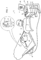
- FIG. 1 is a schematic, pictorial illustration of an intracardiac mapping system 20 that implements visualization of catheter-tissue contact by map distortion, in accordance with an embodiment of the present invention.
- System 20 comprises a probe 22, such as a catheter, and a control console 24.
- probe 22 is used for diagnostic or therapeutic treatment, such as for mapping electrical potentials in a heart 26 of a patient 28.
- probe 22 may be used, mutatis mutandis, for other therapeutic and/or diagnostic purposes in the heart or in other body organs.
- An operator 30 inserts probe 22 through the vascular system of patient 28 so that a distal end 32 of probe 22 enters a chamber of heart 26.
- System 20 typically uses magnetic position sensing to determine position coordinates of distal end 32 inside heart 26.
- Console 24 comprises a driver circuit 34, which drives field generators 36 placed at known positions external to patient 28, e.g., below the patient's torso.
- a magnetic field sensor 38 within distal end 32 of probe 22 (sensor 38 is shown in more detail in Figure 2 ) generates electrical signals in response to the magnetic fields from the coils, thereby enabling console 24 to determine the position of distal end 32 within the chamber.
- system 20 measures the position of distal end 32 using magnetic-based sensors
- other position tracking techniques may be used (e.g., impedance-based sensors).
- Magnetic position tracking techniques are described, for example, in U.S. Patents 5,391,199 , 5,443,489 , 6,788,967 , 6,690,963 , 5,558,091 , 6,172,499 , 6,177,792 .
- Impedance-based position tracking techniques are described, for example, in U.S. Patents 5,983,126 , 6,456,864 and 5,944,022 .
- operator 30 positions distal end 32 at multiple positions on (or in close proximity to) the inner surface of the chamber.
- an electrode 40 coupled to the distal end measures a certain physiological property (e.g., the local surface electrical potential).
- System 20 correlates the position measurements and the electrical potential measurements.
- the system collects multiple map points, with each map point comprising a coordinate on the inner chamber surface and a respective physiological property measurement at this coordinate.
- Console 24 comprises a processor 42, which collects image data from a medical imaging system (not shown) such as a magnetic resonance imaging (MRI) system, or a computed tomography (CT) system, or a probe mapping system such as the CARTO TM mapping system produced by Biosense Webster Inc., of Diamond Bar, CA.
- MRI magnetic resonance imaging
- CT computed tomography
- probe mapping system such as the CARTO TM mapping system produced by Biosense Webster Inc., of Diamond Bar, CA.
- Processor 42 uses the image data to construct a simulated surface of the cardiac chamber in question. An example method for constructing the simulated surface is described further below.
- Processor 42 then "lays" the electrical potential measurements over the simulated surface produced from the image data.
- Processor 42 displays an image 44 of the simulated surface, with the electrical potential measurements laid thereon (the fusion of the simulated surface and the potential measurements is referred to herein as a map), to operator 30 on a display 46.
- Processor 42 typically comprises a general-purpose computer, with suitable front end and interface circuits for receiving signals from probe 22 and controlling the other components of console 24.
- Processor 42 may be programmed in software to carry out the functions that are described herein.
- the software may be downloaded to console 24 in electronic form, over a network, for example, or it may be provided on non-transitory tangible media, such as optical, magnetic or electronic memory media.
- some or all of the functions of processor 42 may be carried out by dedicated or programmable digital hardware components.
- processor 42 also monitors the signal measurements received from a force sensor 48 within distal end 32 (force sensor 48 is shown in more detail in Figure 2 ), in order to make an accurate evaluation of the force exerted by distal end 32 on endocardial tissue of heart 26.
- processor 42 may create a distorted surface in image 44 indicating the exerted force.
- Processor 42 stores data representing image 44 in a memory 50.
- operator 30 using one or more input devices 52 can control how processor 42 presents the distortion.
- image 44 comprises a three-dimensional representation of heart 26
- the operator can use input devices 52 to control the actual geometrical extent of a vertex representing the force exerted by the distal end. (Such a vertex may occur in a generally conical form if tissue tenting occurs.)
- operator 30 can use input devices 52 to control any coloring and/or shading used to indicate the exerted force.
- Figure 1 shows a particular system configuration
- other system configurations can also be employed to implement embodiments of the present invention, and are thus considered to be within the scope of the present invention.
- the methods described hereinbelow may be applied using position transducers of types other than the magnetic field sensor described above, such as impedance-based or ultrasonic position sensors.
- the term "position transducer" as used herein refers to an element mounted on probe 22 which causes console 24 to receive signals indicative of the coordinates of the distal end.
- the position transducer may thus comprise a receiver on the probe, which generates a position signal to the control unit based on energy received by the transducer; or it may comprise a transmitter, emitting energy that is sensed by a receiver external to the probe.
- the methods described hereinbelow may similarly be applied in therapeutic and diagnostic applications using not only catheters, but also probes of other types, both in the heart and in other body organs and regions.
- FIG. 2 is a schematic sectional view of distal end 32 of probe 22, in accordance with an embodiment of the present invention. Specifically, Figure 2 shows functional elements of distal end 32 used for therapeutic and/or diagnostic activity. Electrode 40 at a distal tip 60 of the probe senses electrical signals in the tissue. Electrode 40 is typically made of a metallic material, such as a platinum/iridium alloy or another suitable material. Alternatively, multiple electrodes (not shown) along the length of the probe may be provided.
- Position sensor 38 transmits a signal to console 24 that is indicative of the location coordinates of distal end 32.
- Position sensor 38 may comprise one or more miniature coils, and typically comprises multiple coils oriented along different axes.
- position sensor 38 may comprise either another type of magnetic sensor, an electrode that serves as a position transducer, or position transducers of other types, such as impedance-based or ultrasonic position sensors.
- Figure 2 shows a probe with a single position sensor, embodiments of the present invention may utilize probes with more than one position sensor.
- driver circuit 34 may drive a magnetic field generator in distal end 32 to generate one or more magnetic fields.
- the coils in generator 36 may be configured to sense the fields and generate signals indicative of the amplitudes of the components of these magnetic fields.
- Processor 42 receives and processes these signals in order to determine the position coordinates of distal end 32 within heart 26.
- Force sensor 48 measures a force applied by distal tip 60 to the endocardial tissue of heart 26 by generating a signal to the console that is indicative of the force exerted by the distal tip on the endocardial tissue.
- the force sensor may comprise a magnetic field transmitter and receiver connected by a spring in distal end 32, and may generate an indication of the force based on measuring the deflection of the spring. Further details of this sort of probe and force sensor are described in U.S. Patent Application Publications 2009/0093806 and 2009/0138007 .
- distal end 32 may comprise another type of force sensor.
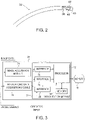
- FIG. 3 is a block diagram that schematically illustrates elements of console 24, in accordance with a disclosed embodiment of the present invention.
- An intracardiac data acquisition module 70 collects force measurements and position signals from probe 22, and conveys the measurements and signals to a visualization module 72.
- An image acquisition module 74 collects image data for heart 26 (typically from an MRI or CT system, as described supra), and conveys the image data to module 72.
- Module 72 comprises interfaces 76 and 78 for communicating with modules 70 and 74, respectively.
- Processor 42 typically stores the collected image data to memory 50.
- Memory 50 may comprise any suitable volatile and/or non-volatile memory, such as random access memory or a hard disk drive.
- processor 42 applies an algorithm (e.g., a fast mapping process) to construct image 44.
- image 44 comprises a simulated 3D surface (e.g., a polygon mesh) of a surface of the cardiac chamber, which processor 42 presents as image 44 on display 46.
- processor 42 may distort image 44 in order to provide operator 30 with a visual representation of the force between distal end 32 and the endocardial tissue.
- examples of the distortion include, but are not limited to a vertex in the simulated surface, as well as coloring and/or shading of a region in the simulated surface corresponding to a location in heart 26 where distal end 32 is applying the force.
- Inputs from input devices 52 via an interface 58 enable operator 30 to adjust the visualization of the distortion. For example, operator 30 can determine how processor 42 presents the distortion on display 46. In other words, based on the operator input, the distortion shown on the simulated surface may not necessary reflect the actual distortion of the heart (e.g., the distortion may exaggerate the force).
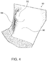
- FIG. 4 is an illustration of a simulated surface 90 showing distortion indicating catheter-tissue contact, in accordance with an embodiment of the present invention.
- simulated surface 90 represents a portion of a wall of heart 26 viewed from the outside of the heart.
- distal end 32 is pressing against endocardial tissue in heart 26, i.e., catheter 22 is within heart 26 and pressing against the heart wall.
- the distortion displayed in simulated surface 90 due to the force exerted by distal end 32 on the heart wall is displayed in a gray scale format as a protruding vertex 92, a dark portion 94, and a light portion 96, thus incorporating a 3D shadowed effect on the surface.
- simulated surface 90 may be visualized from inside heart 26, in which case the distortion may be displayed as a recessed vertex (i.e., a depression in surface 90 instead of protrusion 92). Further alternatively, the distortion may be displayed in a color format.
- FIG. 5 is a flow diagram that schematically illustrates a method of creating a distortion in map 44 in order to visualize catheter-tissue contact, in accordance with an embodiment of the present invention.
- processor 42 Prior to performing an intracardiac procedure, processor 42 collects image data for a chamber of heart 26 from a medical imaging system (e.g., a CARTO TM or an MRI or a CT imaging system), in a first collection step 100.
- the image data typically comprises data points representing tissue of the chamber.
- processor 42 applies an algorithm (e.g., a fast mapping process) to the collected image data in order to construct simulated surface 90.
- algorithm e.g., a fast mapping process
- a threshold set step 104 using input devices 52, operator 30 sets a predefined amount which defines a force threshold.
- the predefined amount may be defined in advance, and stored in memory 50.
- a positioning step 106 operator 30 positions probe 22 so that distal end 32 of the probe is pressing against endocardial tissue of heart 26.
- processor 42 accepts signals from position sensor 38 indicating a position measurement for distal end 32 within heart 26, and signals from force sensor 48 indicating a measurement of the force between distal end 32 and the endocardial tissue.
- a distortion step 112 processor 42 creates a distortion (e.g., protrusion 92) on simulated surface 90 at the location indicated by the position measurement, thereby forming a distorted surface.
- Operator 30 can control the magnitude of the distortion and/or the distortion type (e.g., a protrusion or coloring/shading) using input devices 52.
- processor 42 adjusts the magnitude of the distortion depending on the tissue in contact with distal end 32. Since an atrium of heart 26 has a thinner wall than a ventricle (of the heart), processor 42 introduces a greater degree of distortion in map 44 when the distal end is in contact with atrial tissue (and applying an equivalent force).
- processor 42 presents map 44 which comprises the simulated surface (including any distortion) and relevant potential measurements on display 46, and the method returns to step 106 until operator 30 completes the intracardiac procedure.
- step 110 if the measured force is less than the force threshold, then the method continues with step 114, without introducing any distortion to simulated surface 90.
Landscapes
- Health & Medical Sciences (AREA)
- Life Sciences & Earth Sciences (AREA)
- Surgery (AREA)
- Animal Behavior & Ethology (AREA)
- Pathology (AREA)
- Engineering & Computer Science (AREA)
- Biomedical Technology (AREA)
- Heart & Thoracic Surgery (AREA)
- Medical Informatics (AREA)
- Molecular Biology (AREA)
- Physics & Mathematics (AREA)
- Biophysics (AREA)
- General Health & Medical Sciences (AREA)
- Public Health (AREA)
- Veterinary Medicine (AREA)
- Cardiology (AREA)
- Magnetic Resonance Imaging Apparatus (AREA)
- Measurement And Recording Of Electrical Phenomena And Electrical Characteristics Of The Living Body (AREA)
- Media Introduction/Drainage Providing Device (AREA)
- Apparatus For Radiation Diagnosis (AREA)
Claims (10)
- Appareil, comprenant :une sonde (22), conçue pour être insérée dans une cavité corporelle d'un patient et comprenant un capteur de position (38) pour mesurer une position d'une extrémité distale (32) de la sonde (22) à l'intérieur de la cavité corporelle et un capteur de force (48) pour mesurer une force entre l'extrémité distale (32) et une paroi de la cavité corporelle ; etun processeur (42), qui est conçu pour construire une surface simulée (90) de la cavité corporelle, pour accepter de la sonde (22), tout en pressant l'extrémité distale (32) contre la paroi, des mesures de position indiquant une position de la sonde (22) à l'intérieur de la cavité corporelle et des mesures de force indiquant une force entre l'extrémité distale (32) et la paroi, pour créer une distorsion dans la surface simulée (90) au niveau de la position indiquée par les mesures de position, de sorte à former une surface déformée, lors de la détection que les mesures de force dépassent une quantité prédéfinie, et pour afficher la surface déformée, dans lequel le processeur est conçu pour ajuster la grandeur de la distorsion en fonction du tissu en contact avec l'extrémité distale, dans lequel le processeur est conçu pour introduire un plus grand degré de distorsion lorsque l'extrémité distale (32) est en contact avec le tissu auriculaire que lorsque l'extrémité distale (32) est en contact avec le tissu ventriculaire et en train d'appliquer une force équivalente.
- Appareil selon la revendication 1, dans lequel le processeur (42) est conçu pour permettre à un utilisateur de commander la grandeur de la distorsion et/ou un type de distorsion.
- Appareil selon la revendication 1, dans lequel le processeur (42) est conçu, à un moment avant la construction de la surface simulée (90), pour collecter, à partir d'un système d'imagerie médicale, des données d'image pour la cavité corporelle.
- Appareil selon la revendication 3, dans lequel le système d'imagerie médicale est sélectionné dans un groupe constitué par un système de mappage de sonde, un système d'imagerie par résonance magnétique et un système de tomodensitométrie.
- Appareil selon la revendication 3, dans lequel le processeur (42) est conçu pour construire la surface simulée (90) en appliquant un processus de mappage rapide aux données d'image.
- Appareil selon la revendication 1, dans lequel la sonde (22) comprend un cathéter intracardiaque.
- Appareil selon la revendication 1, dans lequel le processeur (42) est conçu pour créer la distorsion en incorporant un effet tridimensionnel sur la surface (90).
- Appareil selon la revendication 7, dans lequel l'effet tridimensionnel comprend un sommet (92) faisant saillie depuis la surface simulée, ou un sommet s'enfonçant dans la surface simulée.
- Appareil selon la revendication 1, dans lequel le processeur (42) est conçu pour créer la distorsion en remplissant une région de la surface simulée avec une couleur spécifique correspondant à la force au niveau de la position indiquée par les mesures de position.
- Produit logiciel informatique, conçu pour être utilisé conjointement avec une sonde (22) qui est conçue pour être insérée dans une cavité corporelle d'un patient et comprend un capteur de position (38) pour mesurer une position d'une extrémité distale (32) de la sonde (22) à l'intérieur de la cavité corporelle et un capteur de force (48) pour mesurer une force entre l'extrémité distale (32) et une paroi de la cavité corporelle, le produit comprenant un support non transitoire lisible par ordinateur, dans lequel sont stockées des instructions de programme, lesquelles instructions, lorsqu'elles sont lues par un ordinateur, amènent l'ordinateur à construire une surface simulée (90) de la cavité corporelle, à accepter de la sonde (22), tout en pressant l'extrémité distale (32) contre la paroi, des mesures de position indiquant une position de la sonde (22) à l'intérieur de la cavité corporelle et des mesures de force indiquant une force entre l'extrémité distale (32) et la paroi, à créer une distorsion dans la surface simulée (90) au niveau de la position indiquée par les mesures de position, de sorte à former une surface déformée, lors de la détection du fait que les mesures de force dépassent une quantité prédéfinie, et à afficher la surface déformée, dans lequel la grandeur de la distorsion est ajustée en fonction du tissu en contact avec l'extrémité distale (32), dans lequel un plus grand degré de distorsion est introduit lorsque l'extrémité distale (32) est en contact avec le tissu auriculaire que lorsque l'extrémité distale (32) est en contact avec le tissu ventriculaire et en train d'appliquer une force équivalente.
Applications Claiming Priority (2)
| Application Number | Priority Date | Filing Date | Title |
|---|---|---|---|
| US12/939,259 US8532738B2 (en) | 2010-11-04 | 2010-11-04 | Visualization of catheter-tissue contact by map distortion |
| EP11187708.0A EP2449962B1 (fr) | 2010-11-04 | 2011-11-03 | Visualisation du contact cathéter/tissu par distorsion cartographique |
Related Parent Applications (1)
| Application Number | Title | Priority Date | Filing Date |
|---|---|---|---|
| EP11187708.0A Division EP2449962B1 (fr) | 2010-11-04 | 2011-11-03 | Visualisation du contact cathéter/tissu par distorsion cartographique |
Publications (2)
| Publication Number | Publication Date |
|---|---|
| EP3566646A1 EP3566646A1 (fr) | 2019-11-13 |
| EP3566646B1 true EP3566646B1 (fr) | 2022-10-12 |
Family
ID=44905651
Family Applications (2)
| Application Number | Title | Priority Date | Filing Date |
|---|---|---|---|
| EP19165295.7A Active EP3566646B1 (fr) | 2010-11-04 | 2011-11-03 | Visualisation du contact cathéter/tissu par distorsion cartographique |
| EP11187708.0A Active EP2449962B1 (fr) | 2010-11-04 | 2011-11-03 | Visualisation du contact cathéter/tissu par distorsion cartographique |
Family Applications After (1)
| Application Number | Title | Priority Date | Filing Date |
|---|---|---|---|
| EP11187708.0A Active EP2449962B1 (fr) | 2010-11-04 | 2011-11-03 | Visualisation du contact cathéter/tissu par distorsion cartographique |
Country Status (8)
| Country | Link |
|---|---|
| US (1) | US8532738B2 (fr) |
| EP (2) | EP3566646B1 (fr) |
| JP (1) | JP5885999B2 (fr) |
| CN (1) | CN102551667B (fr) |
| AU (1) | AU2011239366B2 (fr) |
| CA (1) | CA2756630C (fr) |
| ES (1) | ES2727250T3 (fr) |
| IL (1) | IL215746A (fr) |
Families Citing this family (27)
| Publication number | Priority date | Publication date | Assignee | Title |
|---|---|---|---|---|
| US9713435B2 (en) * | 2011-07-27 | 2017-07-25 | Biosense Webster (Israel) Ltd. | Cardiac mapping using non-gated MRI |
| US9775578B2 (en) | 2013-08-12 | 2017-10-03 | Biosense Webster (Israel) Ltd. | Unmapped region visualization |
| RU2016139689A (ru) * | 2014-03-12 | 2018-04-12 | Конинклейке Филипс Н.В. | Система и способ тактильной обратной связи для чреспищеводного эхокардиограммного зонда с ультразвуковым преобразователем |
| USD761808S1 (en) | 2014-05-01 | 2016-07-19 | St. Jude Medical, Cardiology Division, Inc. | Display screen with transitional graphical user interface |
| USD761313S1 (en) | 2014-05-01 | 2016-07-12 | St. Jude Medical, Cardiology Division, Inc. | Display screen with a transitional graphical user interface |
| WO2015168200A1 (fr) | 2014-05-01 | 2015-11-05 | St. Jude Medical, Cardiology Division, Inc. | Force de représentation |
| US9615764B2 (en) | 2014-11-03 | 2017-04-11 | Biosense Webster (Israel) Ltd | Real-time coloring of electrophysiological map |
| US10828106B2 (en) | 2015-05-12 | 2020-11-10 | Navix International Limited | Fiducial marking for image-electromagnetic field registration |
| US10507056B2 (en) | 2015-10-01 | 2019-12-17 | General Electric Company | System and method for representation and visualization of catheter applied force and power |
| WO2017136548A1 (fr) | 2016-02-04 | 2017-08-10 | Cardiac Pacemakers, Inc. | Système de pose avec capteur de force pour dispositif cardiaque sans fil |
| WO2018092063A1 (fr) | 2016-11-16 | 2018-05-24 | Navix International Limited | Affichage en temps réel de changements de tissu liés au traitement à l'aide d'un matériau virtuel |
| CN110198680B (zh) | 2016-11-16 | 2022-09-13 | 纳维斯国际有限公司 | 消融有效性估计器 |
| US11284813B2 (en) | 2016-11-16 | 2022-03-29 | Navix International Limited | Real-time display of tissue deformation by interactions with an intra-body probe |
| WO2018092059A1 (fr) * | 2016-11-16 | 2018-05-24 | Navix International Limited | Rendu visuel dynamique de modèle de tissu |
| US11653853B2 (en) | 2016-11-29 | 2023-05-23 | Biosense Webster (Israel) Ltd. | Visualization of distances to walls of anatomical cavities |
| US10510171B2 (en) | 2016-11-29 | 2019-12-17 | Biosense Webster (Israel) Ltd. | Visualization of anatomical cavities |
| JP2019017411A (ja) * | 2017-07-11 | 2019-02-07 | 株式会社日立製作所 | 光音響型カテーテルシステム及び光音響型カテーテル制御方法 |
| US11304603B2 (en) * | 2017-08-21 | 2022-04-19 | Biosense Webster (Israel) Ltd. | Advanced current location (ACL) automatic map rotation to detect holes in current position map (CPM) mapping |
| US10864046B2 (en) | 2017-12-04 | 2020-12-15 | Acclarent, Inc. | Dilation instrument with navigation and distally located force sensor |
| US10918310B2 (en) * | 2018-01-03 | 2021-02-16 | Biosense Webster (Israel) Ltd. | Fast anatomical mapping (FAM) using volume filling |
| IT201800007825A1 (it) * | 2018-08-03 | 2020-02-03 | St Europeo Di Oncologia Srl | Sistema elettronico e sonda per la rilevazione di masse tumorali. |
| EP3677186A1 (fr) | 2019-01-03 | 2020-07-08 | Siemens Healthcare GmbH | Dispositif d'imagerie médicale, système et procédé pour générer une image à compensation de mouvement et support d'enregistrement correspondant |
| IL272254B2 (en) | 2019-02-15 | 2023-04-01 | Biosense Webster Israel Ltd | Catheter for insertion through the esophagus with a carbon dioxide transfer system for thermal protection of the esophagus |
| US20210186642A1 (en) | 2019-12-23 | 2021-06-24 | Ethicon, Inc. | Esophageal Protection Pathways |
| US20210186601A1 (en) | 2019-12-23 | 2021-06-24 | Ethicon, Inc. | Transesophageal Catheter for Thermal Protection of the Esophagus |
| US20210187242A1 (en) | 2019-12-23 | 2021-06-24 | Ethicon, Inc. | Fluid Delivery System for Creating Separation Between Biological Surfaces |
| WO2022264011A1 (fr) | 2021-06-14 | 2022-12-22 | Ethicon, Inc. | Cathéter à système d'administration de dioxyde de carbone et procédé |
Citations (1)
| Publication number | Priority date | Publication date | Assignee | Title |
|---|---|---|---|---|
| EP2201890B1 (fr) * | 2008-12-23 | 2013-01-23 | Biosense Webster, Inc. | Écran de cathéter affichant l'angle de la pointe et la pression |
Family Cites Families (30)
| Publication number | Priority date | Publication date | Assignee | Title |
|---|---|---|---|---|
| US5391199A (en) | 1993-07-20 | 1995-02-21 | Biosense, Inc. | Apparatus and method for treating cardiac arrhythmias |
| US5558091A (en) | 1993-10-06 | 1996-09-24 | Biosense, Inc. | Magnetic determination of position and orientation |
| US5876336A (en) | 1994-10-11 | 1999-03-02 | Ep Technologies, Inc. | Systems and methods for guiding movable electrode elements within multiple-electrode structure |
| US6690963B2 (en) | 1995-01-24 | 2004-02-10 | Biosense, Inc. | System for determining the location and orientation of an invasive medical instrument |
| US5697377A (en) | 1995-11-22 | 1997-12-16 | Medtronic, Inc. | Catheter mapping system and method |
| US6177792B1 (en) | 1996-03-26 | 2001-01-23 | Bisense, Inc. | Mutual induction correction for radiator coils of an objects tracking system |
| US5944022A (en) | 1997-04-28 | 1999-08-31 | American Cardiac Ablation Co. Inc. | Catheter positioning system |
| US6490474B1 (en) * | 1997-08-01 | 2002-12-03 | Cardiac Pathways Corporation | System and method for electrode localization using ultrasound |
| WO1999017265A1 (fr) * | 1997-09-26 | 1999-04-08 | Boston Dynamics, Inc. | Procede et appareil d'entrainement chirurgical et de simulation d'operation chirurgicale |
| US6810281B2 (en) | 2000-12-21 | 2004-10-26 | Endovia Medical, Inc. | Medical mapping system |
| US6298257B1 (en) * | 1999-09-22 | 2001-10-02 | Sterotaxis, Inc. | Cardiac methods and system |
| US6172499B1 (en) | 1999-10-29 | 2001-01-09 | Ascension Technology Corporation | Eddy current error-reduced AC magnetic position measurement system |
| US6892091B1 (en) * | 2000-02-18 | 2005-05-10 | Biosense, Inc. | Catheter, method and apparatus for generating an electrical map of a chamber of the heart |
| US10258285B2 (en) * | 2004-05-28 | 2019-04-16 | St. Jude Medical, Atrial Fibrillation Division, Inc. | Robotic surgical system and method for automated creation of ablation lesions |
| US7632265B2 (en) * | 2004-05-28 | 2009-12-15 | St. Jude Medical, Atrial Fibrillation Division, Inc. | Radio frequency ablation servo catheter and method |
| US8075498B2 (en) | 2005-03-04 | 2011-12-13 | Endosense Sa | Medical apparatus system having optical fiber load sensing capability |
| US20070062546A1 (en) | 2005-06-02 | 2007-03-22 | Viswanathan Raju R | Electrophysiology catheter and system for gentle and firm wall contact |
| US8162935B2 (en) | 2005-10-27 | 2012-04-24 | St. Jude Medical, Atrial Fibrillation Division, Inc. | Systems and methods for electrode contact assessment |
| US8403925B2 (en) | 2006-12-06 | 2013-03-26 | St. Jude Medical, Atrial Fibrillation Division, Inc. | System and method for assessing lesions in tissue |
| WO2007098494A1 (fr) | 2006-02-22 | 2007-08-30 | Hansen Medical, Inc. | Systeme et appareil de mesure des forces distales sur un instrument de travail |
| US8048063B2 (en) | 2006-06-09 | 2011-11-01 | Endosense Sa | Catheter having tri-axial force sensor |
| US20090076476A1 (en) | 2007-08-15 | 2009-03-19 | Hansen Medical, Inc. | Systems and methods employing force sensing for mapping intra-body tissue |
| US8131379B2 (en) | 2007-08-27 | 2012-03-06 | St. Jude Medical Atrial Fibrillation Division, Inc. | Cardiac tissue elasticity sensing |
| US8357152B2 (en) | 2007-10-08 | 2013-01-22 | Biosense Webster (Israel), Ltd. | Catheter with pressure sensing |
| US8535308B2 (en) | 2007-10-08 | 2013-09-17 | Biosense Webster (Israel), Ltd. | High-sensitivity pressure-sensing probe |
| US8340379B2 (en) * | 2008-03-07 | 2012-12-25 | Inneroptic Technology, Inc. | Systems and methods for displaying guidance data based on updated deformable imaging data |
| US8532734B2 (en) | 2008-04-18 | 2013-09-10 | Regents Of The University Of Minnesota | Method and apparatus for mapping a structure |
| US8594841B2 (en) | 2008-12-31 | 2013-11-26 | Intuitive Surgical Operations, Inc. | Visual force feedback in a minimally invasive surgical procedure |
| JP5786108B2 (ja) | 2009-05-08 | 2015-09-30 | セント・ジュード・メディカル・ルクセンブルク・ホールディング・エスエーアールエル | カテーテルアブレーション治療において病変部サイズを制御するための方法および装置 |
| US8311791B1 (en) * | 2009-10-19 | 2012-11-13 | Surgical Theater LLC | Method and system for simulating surgical procedures |
-
2010
- 2010-11-04 US US12/939,259 patent/US8532738B2/en active Active
-
2011
- 2011-10-23 IL IL215746A patent/IL215746A/en active IP Right Grant
- 2011-10-27 AU AU2011239366A patent/AU2011239366B2/en active Active
- 2011-11-01 CA CA2756630A patent/CA2756630C/fr active Active
- 2011-11-02 JP JP2011240962A patent/JP5885999B2/ja active Active
- 2011-11-03 EP EP19165295.7A patent/EP3566646B1/fr active Active
- 2011-11-03 ES ES11187708T patent/ES2727250T3/es active Active
- 2011-11-03 EP EP11187708.0A patent/EP2449962B1/fr active Active
- 2011-11-04 CN CN201110372686.3A patent/CN102551667B/zh active Active
Patent Citations (1)
| Publication number | Priority date | Publication date | Assignee | Title |
|---|---|---|---|---|
| EP2201890B1 (fr) * | 2008-12-23 | 2013-01-23 | Biosense Webster, Inc. | Écran de cathéter affichant l'angle de la pointe et la pression |
Also Published As
| Publication number | Publication date |
|---|---|
| ES2727250T3 (es) | 2019-10-15 |
| AU2011239366B2 (en) | 2014-09-18 |
| EP3566646A1 (fr) | 2019-11-13 |
| AU2011239366A1 (en) | 2012-05-24 |
| IL215746A0 (en) | 2011-12-29 |
| EP2449962A1 (fr) | 2012-05-09 |
| US8532738B2 (en) | 2013-09-10 |
| US20120116210A1 (en) | 2012-05-10 |
| CN102551667A (zh) | 2012-07-11 |
| EP2449962B1 (fr) | 2019-03-27 |
| IL215746A (en) | 2014-08-31 |
| JP5885999B2 (ja) | 2016-03-16 |
| CA2756630C (fr) | 2020-01-14 |
| CN102551667B (zh) | 2015-12-16 |
| JP2012096037A (ja) | 2012-05-24 |
| CA2756630A1 (fr) | 2012-05-04 |
Similar Documents
| Publication | Publication Date | Title |
|---|---|---|
| EP3566646B1 (fr) | Visualisation du contact cathéter/tissu par distorsion cartographique | |
| US9603669B2 (en) | Pressure sensing for a multi-arm catheter | |
| EP2837328B1 (fr) | Visualisation de région non mappée | |
| EP3412201B1 (fr) | Cartographie de données de sonde faisant appel à des informations de contact | |
| JP6537837B2 (ja) | 改良された心電図記録(ecg)グラフの表示 | |
| EP3797691A1 (fr) | Présentation d'activité intracardiaque en 3d | |
| CA2833518A1 (fr) | Utilisation de mesures d'emplacement et de force pour estimer l'epaisseur des tissus | |
| AU2015203370B2 (en) | Pressure sensing for a multi-arm catheter |
Legal Events
| Date | Code | Title | Description |
|---|---|---|---|
| PUAI | Public reference made under article 153(3) epc to a published international application that has entered the european phase |
Free format text: ORIGINAL CODE: 0009012 |
|
| STAA | Information on the status of an ep patent application or granted ep patent |
Free format text: STATUS: THE APPLICATION HAS BEEN PUBLISHED |
|
| AC | Divisional application: reference to earlier application |
Ref document number: 2449962 Country of ref document: EP Kind code of ref document: P |
|
| AK | Designated contracting states |
Kind code of ref document: A1 Designated state(s): AL AT BE BG CH CY CZ DE DK EE ES FI FR GB GR HR HU IE IS IT LI LT LU LV MC MK MT NL NO PL PT RO RS SE SI SK SM TR |
|
| STAA | Information on the status of an ep patent application or granted ep patent |
Free format text: STATUS: REQUEST FOR EXAMINATION WAS MADE |
|
| 17P | Request for examination filed |
Effective date: 20200421 |
|
| RBV | Designated contracting states (corrected) |
Designated state(s): AL AT BE BG CH CY CZ DE DK EE ES FI FR GB GR HR HU IE IS IT LI LT LU LV MC MK MT NL NO PL PT RO RS SE SI SK SM TR |
|
| REG | Reference to a national code |
Ref country code: DE Ref legal event code: R079 Ref document number: 602011073372 Country of ref document: DE Free format text: PREVIOUS MAIN CLASS: A61B0005042000 Ipc: A61B0005053800 |
|
| GRAP | Despatch of communication of intention to grant a patent |
Free format text: ORIGINAL CODE: EPIDOSNIGR1 |
|
| STAA | Information on the status of an ep patent application or granted ep patent |
Free format text: STATUS: GRANT OF PATENT IS INTENDED |
|
| RIC1 | Information provided on ipc code assigned before grant |
Ipc: A61B 5/027 20060101ALI20220627BHEP Ipc: A61B 5/0538 20210101AFI20220627BHEP |
|
| INTG | Intention to grant announced |
Effective date: 20220715 |
|
| GRAS | Grant fee paid |
Free format text: ORIGINAL CODE: EPIDOSNIGR3 |
|
| GRAA | (expected) grant |
Free format text: ORIGINAL CODE: 0009210 |
|
| STAA | Information on the status of an ep patent application or granted ep patent |
Free format text: STATUS: THE PATENT HAS BEEN GRANTED |
|
| AC | Divisional application: reference to earlier application |
Ref document number: 2449962 Country of ref document: EP Kind code of ref document: P |
|
| AK | Designated contracting states |
Kind code of ref document: B1 Designated state(s): AL AT BE BG CH CY CZ DE DK EE ES FI FR GB GR HR HU IE IS IT LI LT LU LV MC MK MT NL NO PL PT RO RS SE SI SK SM TR |
|
| REG | Reference to a national code |
Ref country code: GB Ref legal event code: FG4D |
|
| REG | Reference to a national code |
Ref country code: CH Ref legal event code: EP |
|
| REG | Reference to a national code |
Ref country code: DE Ref legal event code: R096 Ref document number: 602011073372 Country of ref document: DE |
|
| REG | Reference to a national code |
Ref country code: IE Ref legal event code: FG4D |
|
| REG | Reference to a national code |
Ref country code: AT Ref legal event code: REF Ref document number: 1523670 Country of ref document: AT Kind code of ref document: T Effective date: 20221115 |
|
| REG | Reference to a national code |
Ref country code: NL Ref legal event code: FP |
|
| PGFP | Annual fee paid to national office [announced via postgrant information from national office to epo] |
Ref country code: NL Payment date: 20221019 Year of fee payment: 12 |
|
| REG | Reference to a national code |
Ref country code: LT Ref legal event code: MG9D |
|
| REG | Reference to a national code |
Ref country code: AT Ref legal event code: MK05 Ref document number: 1523670 Country of ref document: AT Kind code of ref document: T Effective date: 20221012 |
|
| PG25 | Lapsed in a contracting state [announced via postgrant information from national office to epo] |
Ref country code: SE Free format text: LAPSE BECAUSE OF FAILURE TO SUBMIT A TRANSLATION OF THE DESCRIPTION OR TO PAY THE FEE WITHIN THE PRESCRIBED TIME-LIMIT Effective date: 20221012 Ref country code: PT Free format text: LAPSE BECAUSE OF FAILURE TO SUBMIT A TRANSLATION OF THE DESCRIPTION OR TO PAY THE FEE WITHIN THE PRESCRIBED TIME-LIMIT Effective date: 20230213 Ref country code: NO Free format text: LAPSE BECAUSE OF FAILURE TO SUBMIT A TRANSLATION OF THE DESCRIPTION OR TO PAY THE FEE WITHIN THE PRESCRIBED TIME-LIMIT Effective date: 20230112 Ref country code: LT Free format text: LAPSE BECAUSE OF FAILURE TO SUBMIT A TRANSLATION OF THE DESCRIPTION OR TO PAY THE FEE WITHIN THE PRESCRIBED TIME-LIMIT Effective date: 20221012 Ref country code: FI Free format text: LAPSE BECAUSE OF FAILURE TO SUBMIT A TRANSLATION OF THE DESCRIPTION OR TO PAY THE FEE WITHIN THE PRESCRIBED TIME-LIMIT Effective date: 20221012 Ref country code: ES Free format text: LAPSE BECAUSE OF FAILURE TO SUBMIT A TRANSLATION OF THE DESCRIPTION OR TO PAY THE FEE WITHIN THE PRESCRIBED TIME-LIMIT Effective date: 20221012 Ref country code: AT Free format text: LAPSE BECAUSE OF FAILURE TO SUBMIT A TRANSLATION OF THE DESCRIPTION OR TO PAY THE FEE WITHIN THE PRESCRIBED TIME-LIMIT Effective date: 20221012 |
|
| PG25 | Lapsed in a contracting state [announced via postgrant information from national office to epo] |
Ref country code: RS Free format text: LAPSE BECAUSE OF FAILURE TO SUBMIT A TRANSLATION OF THE DESCRIPTION OR TO PAY THE FEE WITHIN THE PRESCRIBED TIME-LIMIT Effective date: 20221012 Ref country code: PL Free format text: LAPSE BECAUSE OF FAILURE TO SUBMIT A TRANSLATION OF THE DESCRIPTION OR TO PAY THE FEE WITHIN THE PRESCRIBED TIME-LIMIT Effective date: 20221012 Ref country code: LV Free format text: LAPSE BECAUSE OF FAILURE TO SUBMIT A TRANSLATION OF THE DESCRIPTION OR TO PAY THE FEE WITHIN THE PRESCRIBED TIME-LIMIT Effective date: 20221012 Ref country code: IS Free format text: LAPSE BECAUSE OF FAILURE TO SUBMIT A TRANSLATION OF THE DESCRIPTION OR TO PAY THE FEE WITHIN THE PRESCRIBED TIME-LIMIT Effective date: 20230212 Ref country code: HR Free format text: LAPSE BECAUSE OF FAILURE TO SUBMIT A TRANSLATION OF THE DESCRIPTION OR TO PAY THE FEE WITHIN THE PRESCRIBED TIME-LIMIT Effective date: 20221012 Ref country code: GR Free format text: LAPSE BECAUSE OF FAILURE TO SUBMIT A TRANSLATION OF THE DESCRIPTION OR TO PAY THE FEE WITHIN THE PRESCRIBED TIME-LIMIT Effective date: 20230113 |
|
| REG | Reference to a national code |
Ref country code: CH Ref legal event code: PL |
|
| REG | Reference to a national code |
Ref country code: DE Ref legal event code: R097 Ref document number: 602011073372 Country of ref document: DE |
|
| REG | Reference to a national code |
Ref country code: BE Ref legal event code: MM Effective date: 20221130 |
|
| PG25 | Lapsed in a contracting state [announced via postgrant information from national office to epo] |
Ref country code: SM Free format text: LAPSE BECAUSE OF FAILURE TO SUBMIT A TRANSLATION OF THE DESCRIPTION OR TO PAY THE FEE WITHIN THE PRESCRIBED TIME-LIMIT Effective date: 20221012 Ref country code: RO Free format text: LAPSE BECAUSE OF FAILURE TO SUBMIT A TRANSLATION OF THE DESCRIPTION OR TO PAY THE FEE WITHIN THE PRESCRIBED TIME-LIMIT Effective date: 20221012 Ref country code: MC Free format text: LAPSE BECAUSE OF FAILURE TO SUBMIT A TRANSLATION OF THE DESCRIPTION OR TO PAY THE FEE WITHIN THE PRESCRIBED TIME-LIMIT Effective date: 20221012 Ref country code: LI Free format text: LAPSE BECAUSE OF NON-PAYMENT OF DUE FEES Effective date: 20221130 Ref country code: EE Free format text: LAPSE BECAUSE OF FAILURE TO SUBMIT A TRANSLATION OF THE DESCRIPTION OR TO PAY THE FEE WITHIN THE PRESCRIBED TIME-LIMIT Effective date: 20221012 Ref country code: DK Free format text: LAPSE BECAUSE OF FAILURE TO SUBMIT A TRANSLATION OF THE DESCRIPTION OR TO PAY THE FEE WITHIN THE PRESCRIBED TIME-LIMIT Effective date: 20221012 Ref country code: CZ Free format text: LAPSE BECAUSE OF FAILURE TO SUBMIT A TRANSLATION OF THE DESCRIPTION OR TO PAY THE FEE WITHIN THE PRESCRIBED TIME-LIMIT Effective date: 20221012 Ref country code: CH Free format text: LAPSE BECAUSE OF NON-PAYMENT OF DUE FEES Effective date: 20221130 |
|
| PLBE | No opposition filed within time limit |
Free format text: ORIGINAL CODE: 0009261 |
|
| STAA | Information on the status of an ep patent application or granted ep patent |
Free format text: STATUS: NO OPPOSITION FILED WITHIN TIME LIMIT |
|
| PG25 | Lapsed in a contracting state [announced via postgrant information from national office to epo] |
Ref country code: SK Free format text: LAPSE BECAUSE OF FAILURE TO SUBMIT A TRANSLATION OF THE DESCRIPTION OR TO PAY THE FEE WITHIN THE PRESCRIBED TIME-LIMIT Effective date: 20221012 Ref country code: LU Free format text: LAPSE BECAUSE OF NON-PAYMENT OF DUE FEES Effective date: 20221103 Ref country code: AL Free format text: LAPSE BECAUSE OF FAILURE TO SUBMIT A TRANSLATION OF THE DESCRIPTION OR TO PAY THE FEE WITHIN THE PRESCRIBED TIME-LIMIT Effective date: 20221012 |
|
| 26N | No opposition filed |
Effective date: 20230713 |
|
| PG25 | Lapsed in a contracting state [announced via postgrant information from national office to epo] |
Ref country code: IE Free format text: LAPSE BECAUSE OF NON-PAYMENT OF DUE FEES Effective date: 20221103 |
|
| PGFP | Annual fee paid to national office [announced via postgrant information from national office to epo] |
Ref country code: GB Payment date: 20230928 Year of fee payment: 13 |
|
| PG25 | Lapsed in a contracting state [announced via postgrant information from national office to epo] |
Ref country code: SI Free format text: LAPSE BECAUSE OF FAILURE TO SUBMIT A TRANSLATION OF THE DESCRIPTION OR TO PAY THE FEE WITHIN THE PRESCRIBED TIME-LIMIT Effective date: 20221012 Ref country code: BE Free format text: LAPSE BECAUSE OF NON-PAYMENT OF DUE FEES Effective date: 20221130 |
|
| PGFP | Annual fee paid to national office [announced via postgrant information from national office to epo] |
Ref country code: FR Payment date: 20230929 Year of fee payment: 13 |
|
| PGFP | Annual fee paid to national office [announced via postgrant information from national office to epo] |
Ref country code: DE Payment date: 20230929 Year of fee payment: 13 Ref country code: IT Payment date: 20231010 Year of fee payment: 13 |
|
| PG25 | Lapsed in a contracting state [announced via postgrant information from national office to epo] |
Ref country code: HU Free format text: LAPSE BECAUSE OF FAILURE TO SUBMIT A TRANSLATION OF THE DESCRIPTION OR TO PAY THE FEE WITHIN THE PRESCRIBED TIME-LIMIT; INVALID AB INITIO Effective date: 20111103 |
|
| PG25 | Lapsed in a contracting state [announced via postgrant information from national office to epo] |
Ref country code: CY Free format text: LAPSE BECAUSE OF FAILURE TO SUBMIT A TRANSLATION OF THE DESCRIPTION OR TO PAY THE FEE WITHIN THE PRESCRIBED TIME-LIMIT Effective date: 20221012 |