EP3565994B1 - Metallischer gartenschlauch mit zugentlastung - Google Patents
Metallischer gartenschlauch mit zugentlastung Download PDFInfo
- Publication number
- EP3565994B1 EP3565994B1 EP18736101.9A EP18736101A EP3565994B1 EP 3565994 B1 EP3565994 B1 EP 3565994B1 EP 18736101 A EP18736101 A EP 18736101A EP 3565994 B1 EP3565994 B1 EP 3565994B1
- Authority
- EP
- European Patent Office
- Prior art keywords
- hose
- assembly
- strain relief
- metal shell
- fitting
- Prior art date
- Legal status (The legal status is an assumption and is not a legal conclusion. Google has not performed a legal analysis and makes no representation as to the accuracy of the status listed.)
- Active
Links
Images


Classifications
-
- F—MECHANICAL ENGINEERING; LIGHTING; HEATING; WEAPONS; BLASTING
- F16—ENGINEERING ELEMENTS AND UNITS; GENERAL MEASURES FOR PRODUCING AND MAINTAINING EFFECTIVE FUNCTIONING OF MACHINES OR INSTALLATIONS; THERMAL INSULATION IN GENERAL
- F16L—PIPES; JOINTS OR FITTINGS FOR PIPES; SUPPORTS FOR PIPES, CABLES OR PROTECTIVE TUBING; MEANS FOR THERMAL INSULATION IN GENERAL
- F16L11/00—Hoses, i.e. flexible pipes
- F16L11/04—Hoses, i.e. flexible pipes made of rubber or flexible plastics
- F16L11/10—Hoses, i.e. flexible pipes made of rubber or flexible plastics with reinforcements not embedded in the wall
-
- F—MECHANICAL ENGINEERING; LIGHTING; HEATING; WEAPONS; BLASTING
- F16—ENGINEERING ELEMENTS AND UNITS; GENERAL MEASURES FOR PRODUCING AND MAINTAINING EFFECTIVE FUNCTIONING OF MACHINES OR INSTALLATIONS; THERMAL INSULATION IN GENERAL
- F16L—PIPES; JOINTS OR FITTINGS FOR PIPES; SUPPORTS FOR PIPES, CABLES OR PROTECTIVE TUBING; MEANS FOR THERMAL INSULATION IN GENERAL
- F16L33/00—Arrangements for connecting hoses to rigid members; Rigid hose-connectors, i.e. single members engaging both hoses
- F16L33/20—Undivided rings, sleeves, or like members contracted on the hose or expanded inside the hose by means of tools; Arrangements using such members
- F16L33/207—Undivided rings, sleeves, or like members contracted on the hose or expanded inside the hose by means of tools; Arrangements using such members only a sleeve being contracted on the hose
- F16L33/2071—Undivided rings, sleeves, or like members contracted on the hose or expanded inside the hose by means of tools; Arrangements using such members only a sleeve being contracted on the hose the sleeve being a separate connecting member
- F16L33/2073—Undivided rings, sleeves, or like members contracted on the hose or expanded inside the hose by means of tools; Arrangements using such members only a sleeve being contracted on the hose the sleeve being a separate connecting member directly connected to the rigid member
- F16L33/2076—Undivided rings, sleeves, or like members contracted on the hose or expanded inside the hose by means of tools; Arrangements using such members only a sleeve being contracted on the hose the sleeve being a separate connecting member directly connected to the rigid member by plastic deformation
-
- E—FIXED CONSTRUCTIONS
- E03—WATER SUPPLY; SEWERAGE
- E03F—SEWERS; CESSPOOLS
- E03F1/00—Methods, systems, or installations for draining-off sewage or storm water
-
- F—MECHANICAL ENGINEERING; LIGHTING; HEATING; WEAPONS; BLASTING
- F16—ENGINEERING ELEMENTS AND UNITS; GENERAL MEASURES FOR PRODUCING AND MAINTAINING EFFECTIVE FUNCTIONING OF MACHINES OR INSTALLATIONS; THERMAL INSULATION IN GENERAL
- F16L—PIPES; JOINTS OR FITTINGS FOR PIPES; SUPPORTS FOR PIPES, CABLES OR PROTECTIVE TUBING; MEANS FOR THERMAL INSULATION IN GENERAL
- F16L19/00—Joints in which sealing surfaces are pressed together by means of a member, e.g. a swivel nut, screwed on, or into, one of the joint parts
- F16L19/02—Pipe ends provided with collars or flanges, integral with the pipe or not, pressed together by a screwed member
- F16L19/0206—Pipe ends provided with collars or flanges, integral with the pipe or not, pressed together by a screwed member the collar not being integral with the pipe
-
- F—MECHANICAL ENGINEERING; LIGHTING; HEATING; WEAPONS; BLASTING
- F16—ENGINEERING ELEMENTS AND UNITS; GENERAL MEASURES FOR PRODUCING AND MAINTAINING EFFECTIVE FUNCTIONING OF MACHINES OR INSTALLATIONS; THERMAL INSULATION IN GENERAL
- F16L—PIPES; JOINTS OR FITTINGS FOR PIPES; SUPPORTS FOR PIPES, CABLES OR PROTECTIVE TUBING; MEANS FOR THERMAL INSULATION IN GENERAL
- F16L27/00—Adjustable joints; Joints allowing movement
- F16L27/02—Universal joints, i.e. with mechanical connection allowing angular movement or adjustment of the axes of the parts in any direction
- F16L27/04—Universal joints, i.e. with mechanical connection allowing angular movement or adjustment of the axes of the parts in any direction with partly-spherical engaging surfaces
-
- F—MECHANICAL ENGINEERING; LIGHTING; HEATING; WEAPONS; BLASTING
- F16—ENGINEERING ELEMENTS AND UNITS; GENERAL MEASURES FOR PRODUCING AND MAINTAINING EFFECTIVE FUNCTIONING OF MACHINES OR INSTALLATIONS; THERMAL INSULATION IN GENERAL
- F16L—PIPES; JOINTS OR FITTINGS FOR PIPES; SUPPORTS FOR PIPES, CABLES OR PROTECTIVE TUBING; MEANS FOR THERMAL INSULATION IN GENERAL
- F16L57/00—Protection of pipes or objects of similar shape against external or internal damage or wear
- F16L57/005—Protection of pipes or objects of similar shape against external or internal damage or wear specially adapted for the ends of pipes
-
- F—MECHANICAL ENGINEERING; LIGHTING; HEATING; WEAPONS; BLASTING
- F16—ENGINEERING ELEMENTS AND UNITS; GENERAL MEASURES FOR PRODUCING AND MAINTAINING EFFECTIVE FUNCTIONING OF MACHINES OR INSTALLATIONS; THERMAL INSULATION IN GENERAL
- F16L—PIPES; JOINTS OR FITTINGS FOR PIPES; SUPPORTS FOR PIPES, CABLES OR PROTECTIVE TUBING; MEANS FOR THERMAL INSULATION IN GENERAL
- F16L57/00—Protection of pipes or objects of similar shape against external or internal damage or wear
- F16L57/02—Protection of pipes or objects of similar shape against external or internal damage or wear against cracking or buckling
Definitions
- the present invention relates to a water hose and more particularly to a metal garden hose assembly that is resistant to damage from strain and stresses during use.
- a type of hose that is often used in industrial settings has a braided or coiled metal outer hose encasing a flexible inner rubber or PVC hose.
- Metal-shelled hoses possess several desirable features, include resistance to burst, crush, puncture, and abrasion. Such hoses are comparable in weight to conventional rubber hoses, or even lighter, but are easier to flex for positioning, provided that the degree of curvature is large enough that they are not forced to bend at a sharp angle.
- the bending limitation tends not to be a problem in industrial applications, where hoses are used to attach a stationary machine to a water source and are not subject to frequent re-positioning, however, it can become a significant problem for use in the garden or around the home, where stretching and pulling on the hose around corners are commonplace. Since the usual manner of reaching a remote location with a garden hose is to keep pulling until it stops, a considerable amount of stress and strain can be applied to fitting at the faucet end of the hose.
- a rubber or flat hose may be able to hold up to being pulled at a relatively sharp angle near the faucet end
- the outer shell of a metal hose is susceptible to kinks and breakage if pulled too forcefully at an angle that is less that the natural curvature of the metal shell, permanently crimping or distorting the protective metal coils and exposing the inner tubing to damage.
- existing metal-shelled hoses are not constructed to tolerate the abuse to which everyday garden hoses are frequently subjected.
- US 2016/312940 A1 discloses a garden hose coupling with a protective strain reducing sleeve.
- US 1 179 552 A discloses a hose coupling and mender.
- GB 2 532 783 A discloses a hydraulic fitting and method for manufacturing such a fitting.
- US 4 991 876 A discloses a connector assembly for hot water heaters and other appliances.
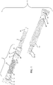
- FIGs. 1-3 illustrate the components of an embodiment of the metal-shelled hose 10 with strain relief according to the invention. Improvements provided by the present invention include strain relief assembly 4, which minimizes the risk of damage to the hose resulting from bending or pulling it around a sharp corner.
- the basic elements of the hose include conventional hose fittings, corresponding to the female fitting 8 that attaches to a hose bib or faucet via threads or a quick connect fitting, and a male fitting 34 which can be connected to another length of hose or a spray nozzle.
- the fittings 8 and 34 may be formed from metal such as brass, steel, aluminum or other appropriate metal, or may be a durable plastic or polymer.
- a single strain relief assembly 4 is provided at the faucet end, which may also be referred to herein as the "proximal end”.
- a strain relief section may be included near the outlet end, alternatively referred to as the "distal end.”
- the length of hose between the proximal and distal ends is formed from a combination of a metal outer shell 12 and a lightweight, flexible synthetic inner tubing 14, for example PVC, PTFE, latex, rubber, or other appropriate material, preferably selected from commercially-available options that are certified by NSF International as drinking water safe (e.g., NSF-61).
- Outer shell 12 may be formed from stainless steel, e.g., 304 stainless, galvanized steel, painted or powder-coated non-stainless steel, aluminum, nickel, copper, or other appropriate durable metal.
- 304 stainless steel is formed as a stripwound interlocked coil using known manufacturing techniques.
- Such tubing construction is well-recognized as being lightweight but relatively tough.
- Other appropriate configurations can include braided or corrugated hose.
- Inner tubing 14 is preferably PVC or PTFE, and may be smooth (as illustrated in the figures), with an outer diameter that closely fits the inner diameter of outer shell 12. Alternatively, inner tubing may be convoluted or corrugated to provide additional strength.
- Strain relief assembly 4 includes the following primary components: metal clip 18, flexible tubing 20, metal clip 22, double-ended hose fitting 25 and metal clip 24. Details of these components, and their interconnection with other components can be seen in the exploded views of FIGs. 2 and 3 .
- Flexible tubing 20 is formed from a short section of highly flexible polyurethane, polyvinylchloride (PVC), polytetrafluoroethylene (PTFE), or similar polymer or rubber material, preferably reinforced with polyester or other woven braid. For a typical 3 ⁇ 4 inch garden hose, the diameter of tubing 20 will be around 1.5 to 2 cm ( ⁇ 0.6 to 0.75 in.) outer diameter.
- An exemplary wall thickness for the tubing would be on the order of 1-3 mm (0.08 to 0.125 in.), but will depend on the material used and its pressure specifications. Selection of an appropriate material and dimensions will be within the level of skill in the art. In general, to provide the desired degree of flexibility, a suitable tubing would be sufficiently soft and pliable to be doubled over or fully compressed with one's hand (without the aid of a tool.)
- the length of tubing 20 may be on the order of 5 to 25 cm (-2 to 10 in.). The length may be shorter or longer, however, for manufacturing efficiency and cost, the length would preferably be closer to the shorter end of the range, i.e., 6 to 9 cm (-2.5 to 3.5 in.).
- this connector may include any type of insertable male connector that is commonly used in hose and tubing connections, including barbed, corrugated, threaded, flared, clamping sleeve, or similar insertable coupler, which forms a water-tight, pressure-resistant seal with the inner surface of tubing by way of an interference-type and/or friction fit.
- the first end of tubing 20 is expanded to produce an interference fit over stem connector 7 of flanged fitting 6, which connects female fitting 8 to the hose.
- Metal clip 18 which is a cylinder with a flat end and a rounded end, preferably formed of stainless steel, fits over the outer surface of the first end of tubing 20 and stem connector 7.
- clip 18 may be a swaging collar or similar structure configured to mate with a corresponding stem connector.
- the flat end of metal clip 18 covers the first end of tubing 20, while the rounded end of clip 18 abuts female fitting 8. The rounded end is pressed or crimped to secure it to female fitting 8 position. For example, crimps 15 are illustrated in FIG. 1 .
- the second end of tubing 20 is press fit over stem connector 33 of double-ended hose fitting 25.
- Fitting 25 may be formed from metal, e.g., aluminum or steel, or may be plastic or durable polymer.
- Metal clip 22, with the same flat and rounded construction as clip 18, is crimped (e.g., crimps 23) over the tubing end and barbed connector 33 to secure tubing 20 to fitting 25. Where a swage-style connection is used, appropriate fastening means known in the art may be employed.
- Stem connector 37 is inserted into the proximal end of inner tubing 14 with bushing 35 over the tubing end.
- Bushing 35 may be stainless steel, brass, or other appropriate metal, or may be a durable plastic or polymer.
- the metal clip 24 is slid over the proximal end of the metal shell 12, then over the end 17 of bushing 35 so that the bushing end 17 extends into the proximal end of metal shell 12 between the shell inner surface and the inner tubing 14.
- the rounded end of metal clip 24 is pressed or crimped (crimps 27) to secure the proximal ends of metal shell 12, bushing 35, and inner tubing 14 to hose fitting 25.
- fitting 25 may include a swivel joint to allow relative rotation between the strain relief assembly 4 and the remainder of the hose.
- a protective boot 16 or other tubular sleeve (rubber, metal, silicone, plastic, polymer, or other suitable material, which may be resilient or semi-rigid) may be provided to fit over the entire strain relief portion 4.
- metal clip 32 is slid over the metal shell 12 while the stem connector 33 of male fitting 34 is inserted into the distal end of inner tubing 14 with bushing 31.
- the rounded end of metal clip 32 is pressed, crimped or swaged to secure the fitting 34 to the hose.
- a protective boot 30 or other tubular sleeve (rubber, metal, plastic, polymer, or other suitable material, resilient or semi-rigid) may be provided to enclose the connections.
- the boot 30 will be tapered and rounded to facilitate handling of the hose assembly and prevent that portion of the hose from catching on obstacles, edges and other protrusions in the work area.
- a second strain relief assembly (not shown) may be provided by using the same components as described above.
- FIG. 4 illustrates an example of the inventive hose assembly showing how strain relief section 4 is able to bend at a fairly severe angle, e.g., 90° or smaller relative to the direction of the faucet 60, while the metal shell 12 (and its inner tubing) remains basically straight, or at least is allowed to extend within an appropriate range of curvature for a metal hose while avoiding damage. Even if the strain relief section 4 were to be forced to bend at such an extreme angle so that it collapses on itself, due to its flexibility, any crimping in this section would be reversible -- the hose's metal shell 12 would not be damaged.
- a fairly severe angle e.g. 90° or smaller relative to the direction of the faucet 60
- the metal shell 12 and its inner tubing
- a metal garden hose may incorporate one or more banjo fittings disposed at the female hose (faucet) end to permit bending relative to the faucet.
- banjo fittings could be provided with pivot axes that are perpendicular to each other, to provide two degrees of freedom in the angle at which the hose can be pulled relative to the faucet.
- Another approach would be to incorporate a ball socket on the metal hose to allow the hose to swivel relative to the faucet attachment, as shown in FIGs. 5 and 6 .
- FIG. 5 illustrates the female (faucet-attachment) hose end of an assembly that employs a ball joint to provide the necessary flexibility to prevent bending of the metal outer shell of a metal garden hose.
- the key is to permit the hose to be pulled at an angle relative to the faucet attachment without causing the hose to be pulled at an angle that is less that the permissible arc of the metal outer shell.
- a ball joint which includes ball portion 54 that rotatably and pivotally fits within socket portion 52, has a construction similar to that of joints commonly used for attachment of showerheads.
- the joint may be metal, plastic, polymer, or other durable material.
- socket portion 52 is a two-piece assembly with a threaded attachment to retain the ball head of ball portion 54 within the socket.
- An O-ring 56 provides a water-tight seal within the joint, while water flows through channel 58, which extends through the length of the joint.
- the joint is attached, either directly or via a short section of tubing, at one end to female fitting 50 and at the other end has a barbed (or similar) stem extension 62 (shown in FIG. 6 ) dimensioned for insertion into the hose inner tubing 14.
- a bushing (not shown) may be fitted over the stem extension 62 and end of inner tubing 14, and a cylindrical metal clip 60 is crimped over the end of the metal outer hose 12, the bushing and the stem extension 62 to secure the assembly.
- a boot 16 may be fitted over the strain-relief assembly to facilitate handling and protect the joint from impact and/or dirt.
- the ball-joint strain relief assembly may optionally be added to the male end of the hose as well. While the ball joint illustrated in the figures shows the socket portion 52 connected to the inlet fitting 50, it will be readily apparent to those in the art that the assembly may be reversed, with the ball joint extending from the inlet fitting 50 and the housing connected to the hose.
- the metal garden hose described herein provides a lightweight alternative to conventional rubber hoses, with improved flexibility and durability.
- the protective metal shell makes the hose puncture proof, thorn proof, tear proof, weather proof, kink proof, and animal proof. Because the hose maintains its open inner structure even when water is not flowing under pressure, it avoids the drawbacks of flat garden hoses that require pressure to expand the flow path.
- the strain relief assembly avoids damage to the metal shell that can occur when the hose is pulled around corners or sharp edges, or at any angle that is not in a straight line from the faucet.
Landscapes
- Engineering & Computer Science (AREA)
- General Engineering & Computer Science (AREA)
- Mechanical Engineering (AREA)
- Health & Medical Sciences (AREA)
- Life Sciences & Earth Sciences (AREA)
- Hydrology & Water Resources (AREA)
- Public Health (AREA)
- Water Supply & Treatment (AREA)
- Rigid Pipes And Flexible Pipes (AREA)
Claims (9)
- Schlauchanordnung (10), Folgendes umfassend:eine flexible Metallhülle (12), die ein proximales Ende und ein distales Ende aufweist;einen Innenschlauch (14), der in der Metallhülle angeordnet ist, wobei der Innenschlauch ein proximales Ende und ein distales Ende aufweist;ein Einlassfitting (8), das mit dem proximalen Ende der Metallhülle und des Innenschlauchs verbunden ist, wobei das Einlassfitting für eine lösbare Verbindung mit einer Wasserquelle (60) ausgelegt ist;ein Auslassfitting (34), das mit dem distalen Ende der Metallhülle und des Innenschlauchs verbunden ist, wobei das Auslassfitting einen Auslassschaftverbinder (33) aufweist; undmindestens eine Zugentlastungsanordnung (4), die zumindest zwischen dem Einlassfitting und dem proximalen Ende der Metallhülle und des Innenschlauchs angeordnet ist, wobei die Zugentlastungsanordnung dazu ausgelegt ist,einen Winkel der Metallhülle und des Innenschlauchs in Bezug zur Wasserquelle zu verändern, wenn der Schlauch in Bezug zur Wasserquelle gezogen wird, um ein Verbiegen der Metallhülle zu minimieren, wobei die mindestens eine Zugentlastungsanordnung Folgendes umfasst:
ein flexibles Schlauchelement (20), das ein erstes Ende, ein zweites Ende und einen Durchmesser aufweist, um eine Presspassung über einen Einlassschaftverbinder zu erzeugen (7), der sich vom Einlassfitting am ersten Ende erstreckt; gekennzeichnet durch:eine erste zylindrische Klemme (18), die dazu ausgelegt ist, das erste Ende des Schlauchsegments am Einlassschaftverbinder zu fixieren;ein doppelseitiges Schlauchfitting (25), das ein erstes Schaftende (33) und ein zweites Schaftende (37) aufweist,wobei das erste Schaftende dazu ausgelegt ist, in das zweite Ende des Schlauchsegments zu passen, um eine Presspassung über das erste Schaftende zu erzeugen;eine zweite zylindrische Klemme (22), die dazu ausgelegt ist, das zweite Ende des Schlauchsegments am ersten Schaftende zu fixieren; undeine dritte zylindrische Klemme (24), die dazu ausgelegt ist, die proximalen Enden der Metallhülle und des Innenschlauchs am zweiten Schaftende zu fixieren. - Schlauchanordnung (10) nach Anspruch 1, ferner eine Buchse (31) umfassend, die in der zweiten zylindrischen Klemme angeordnet ist.
- Schlauchanordnung (10) nach Anspruch 1 oder Anspruch 2, ferner eine Buchse (35) umfassend, die in der dritten zylindrischen Klemme (24) angeordnet ist.
- Schlauchanordnung (10) nach einem der Ansprüche 1 bis 3, wobei die mindestens eine Zugentlastungsanordnung (4) eine erste Zugentlastungsanordnung, die an das Einlassfitting (8) angrenzend angeordnet ist, und eine zweite Zugentlastungsanordnung, die an das Auslassfitting (34) angrenzend angeordnet ist, umfasst.
- Schlauchanordnung (10) nach einem der Ansprüche 1 bis 4, wobei die Metallhülle (12) eine gewickelte, ineinandergreifende Spirale aus Edelstahl umfasst.
- Schlauchanordnung (10) nach einem der Ansprüche 1 bis 5, wobei der Innenschlauch Polyvinylchlorid oder Polytetrafluorethylen umfasst.
- Schlauchanordnung (10) nach einem der Ansprüche 1 bis 6, wobei der flexible Schlauch verstärktes Polyvinylchlorid oder Polytetrafluorethylen umfasst.
- Schlauchanordnung (10) nach einem der Ansprüche 1 bis 7, wobei der flexible Schlauch eine Länge im Bereich von 6 bis 25 cm aufweist.
- Schlauchanordnung (10) nach einem der Ansprüche 1 bis 8, ferner eine Schutzmanschette (16) umfassend, die die mindestens eine Zugentlastungsanordnung (4) umschließt.
Applications Claiming Priority (2)
| Application Number | Priority Date | Filing Date | Title |
|---|---|---|---|
| US15/402,129 US10267437B2 (en) | 2017-01-09 | 2017-01-09 | Metal garden hose with strain relief |
| PCT/US2018/012389 WO2018129190A1 (en) | 2017-01-09 | 2018-01-04 | Metal garden hose with strain relief |
Publications (3)
| Publication Number | Publication Date |
|---|---|
| EP3565994A1 EP3565994A1 (de) | 2019-11-13 |
| EP3565994A4 EP3565994A4 (de) | 2020-11-25 |
| EP3565994B1 true EP3565994B1 (de) | 2022-04-06 |
Family
ID=62782760
Family Applications (1)
| Application Number | Title | Priority Date | Filing Date |
|---|---|---|---|
| EP18736101.9A Active EP3565994B1 (de) | 2017-01-09 | 2018-01-04 | Metallischer gartenschlauch mit zugentlastung |
Country Status (4)
| Country | Link |
|---|---|
| US (2) | US10267437B2 (de) |
| EP (1) | EP3565994B1 (de) |
| CN (1) | CN110382937B (de) |
| WO (1) | WO2018129190A1 (de) |
Families Citing this family (14)
| Publication number | Priority date | Publication date | Assignee | Title |
|---|---|---|---|---|
| US10537073B2 (en) | 2012-05-24 | 2020-01-21 | Rain Bird Corporation | Conduit with connector and assembly thereof |
| US10267437B2 (en) * | 2017-01-09 | 2019-04-23 | Yeiser Research & Development LLC | Metal garden hose with strain relief |
| USD925707S1 (en) * | 2018-08-23 | 2021-07-20 | Zhejiang Tianti Rubber & Plastic Technology Co., Ltd. | Garden hose |
| USD935575S1 (en) * | 2018-09-10 | 2021-11-09 | Australian Plumbing Products Pty Ltd | Flexible water hose |
| USD920486S1 (en) * | 2019-05-09 | 2021-05-25 | Graco Minnesota Inc. | Transparently-wrapped electrostatic sprayer fluid tube |
| USD948675S1 (en) * | 2020-02-06 | 2022-04-12 | Telebrands Corporation | Hose with flexible sleeve |
| DE102020203912A1 (de) * | 2020-03-26 | 2021-09-30 | Robert Bosch Gesellschaft mit beschränkter Haftung | Wischblatt, insbesondere für ein Kraftfahrzeug |
| USD1030982S1 (en) * | 2020-11-27 | 2024-06-11 | Zhejiang Tianti Rubber & Plastic Technology Co., Ltd. | Garden hose grip |
| US20240308194A1 (en) * | 2021-02-01 | 2024-09-19 | Contitech Usa, Inc. | Multilayer rubber hose |
| USD939673S1 (en) * | 2021-03-19 | 2021-12-28 | Wen Du | Connective water pipe |
| CN113404946A (zh) * | 2021-06-04 | 2021-09-17 | 广东省第一建筑工程有限公司 | 一种取代氩弧焊的高低压不锈钢管、铜管连接施工工法 |
| US11732826B2 (en) | 2021-11-08 | 2023-08-22 | E. Mishan & Sons, Inc. | Garden hose with metal sheath and fabric cover |
| USD1027135S1 (en) * | 2021-11-14 | 2024-05-14 | Zhejiang Tianti Rubber & Plastic Technology Co., Ltd. | Braided air hose |
| CN120836349A (zh) * | 2025-09-23 | 2025-10-28 | 仲恺农业工程学院 | 一种用于园林绿化养护的防护装置 |
Family Cites Families (44)
| Publication number | Priority date | Publication date | Assignee | Title |
|---|---|---|---|---|
| US762954A (en) * | 1903-05-28 | 1904-06-21 | Theodore Smith | Flexible metallic-covered tubing. |
| US967901A (en) * | 1908-10-03 | 1910-08-23 | Edwin T Greenfield | Hose. |
| US1091759A (en) * | 1913-03-17 | 1914-03-31 | Frederik E Paradis | Hose-coupling. |
| US1179552A (en) * | 1913-08-04 | 1916-04-18 | Lewen R Nelson | Hose coupling and mender. |
| US1528967A (en) * | 1920-11-27 | 1925-03-10 | Martin C Bersted | Flexible conduit |
| US2759765A (en) * | 1954-07-19 | 1956-08-21 | Leon P Pawley | Flexible shower head |
| US3623513A (en) * | 1970-02-16 | 1971-11-30 | Stewart Warner Corp | High-pressure flexible hose sheath |
| US3929164A (en) * | 1971-02-25 | 1975-12-30 | Harold J Richter | Fluid transfer umbilical assembly for use in zero gravity environment |
| MX151632A (es) * | 1980-02-15 | 1985-01-23 | Gould Inc | Mejoras a protector de estallido para mangueras de alta presion |
| US4669757A (en) * | 1982-08-05 | 1987-06-02 | Bartholomew Donald D | High pressure fluid conduit assembly |
| US4991876A (en) * | 1989-07-28 | 1991-02-12 | Euroflex, S.A. | Connector assembly for hot water heaters and other appliances |
| US5143409A (en) | 1989-08-30 | 1992-09-01 | Titeflex Corporation | Stress relief device |
| US5368235A (en) | 1990-08-09 | 1994-11-29 | Plastic Specialties And Technologies, Inc. | Soaker hose assembly |
| US5333650A (en) | 1993-03-17 | 1994-08-02 | Flexon Industries Corporation | Hose coupling with a stiffening sleeve |
| US5624074A (en) | 1995-10-26 | 1997-04-29 | Component Hardware Group, Inc. | Hose sub-assembly |
| JP3506403B2 (ja) * | 1996-05-14 | 2004-03-15 | 東拓工業株式会社 | 洗濯機用ホース |
| US6557788B1 (en) | 2002-06-05 | 2003-05-06 | Dustin Huang | Hose connector |
| DE20211150U1 (de) * | 2002-07-23 | 2002-09-26 | Vohran Patentverwertungs GmbH, 61462 Königstein | Schlauch, insbesondere Sanitärschlauch |
| US20060151038A1 (en) * | 2005-01-13 | 2006-07-13 | Saint-Gobain Performance Plastics Corporation | Coiled air brake hose assembly |
| US20060273191A1 (en) * | 2005-06-02 | 2006-12-07 | Darrell Pastuch | Flexible riser for irrigation means |
| US7302972B1 (en) * | 2005-08-05 | 2007-12-04 | Stowe Alan D | Thermo-insulated flexible tubing |
| US20070079885A1 (en) | 2005-10-11 | 2007-04-12 | Saint-Gobain Performance Plastics Corporation | Hose assembly |
| WO2010131216A1 (en) | 2009-05-12 | 2010-11-18 | Fitt S.P.A. | Reinforced flexible hose with high pressure strenght and method for its manufacturing |
| US8360478B2 (en) | 2010-03-02 | 2013-01-29 | Magnum Shielding Corporation | Sacrificial hose fitting assembly |
| US9909699B2 (en) | 2011-03-17 | 2018-03-06 | Jay G. Bernhardt | Garden hose with spiral guard |
| US8757213B2 (en) | 2011-11-04 | 2014-06-24 | Blue Gentian, Llc | Commercial hose |
| US9261222B2 (en) * | 2011-11-30 | 2016-02-16 | Swan Holdings, Llc | Anti-kinking device for garden or water hose |
| US8936046B2 (en) | 2012-11-09 | 2015-01-20 | Ragner Technology Corporation | Elastic and spring biased retractable hoses |
| US9844921B2 (en) | 2013-08-10 | 2017-12-19 | Ragner Technology Corporation | Annular-pleated circular braid |
| US20150053298A1 (en) | 2013-08-20 | 2015-02-26 | Kevin Alan Tussy | Anti-Kink Tubing |
| US9863565B2 (en) | 2014-11-25 | 2018-01-09 | Teknor Apex Company | Multi-layer expandable hose |
| GB2532783A (en) * | 2014-11-28 | 2016-06-01 | Eaton Ind Ip Gmbh & Co Kg | Hydraulic fitting and method for manufacturing such a fitting |
| USD770601S1 (en) | 2015-04-23 | 2016-11-01 | Teknor Apex Company | Hose with sleeve |
| US9625071B2 (en) | 2015-04-23 | 2017-04-18 | Teknor Apex Company | Garden hose coupling with protective, strain reducing sleeve |
| US9815254B2 (en) | 2015-04-24 | 2017-11-14 | Teknor Apex Company | Lightweight, high flow hose assembly and method of manufacture |
| US10458574B2 (en) | 2015-04-24 | 2019-10-29 | Teknor Apex Company | Lightweight, high flow hose assembly and method of manufacture |
| US10132435B2 (en) | 2015-04-24 | 2018-11-20 | Teknor Apex Company | Lightweight, high flow hose assembly and method of manufacture |
| US10000035B2 (en) | 2015-04-24 | 2018-06-19 | Teknor Apex Company | Lightweight, high flow hose assembly and method of manufacture |
| USD757233S1 (en) | 2015-04-24 | 2016-05-24 | Teknor Apex Company | Male hose fitting |
| USD779640S1 (en) | 2015-04-24 | 2017-02-21 | Teknor Apex Company | Female hose fitting |
| US9810357B2 (en) | 2015-04-24 | 2017-11-07 | Teknor Apex Company | Lightweight, high flow hose assembly and method of manufacture |
| CN107614953B (zh) | 2015-04-24 | 2022-08-05 | 特诺尔艾佩斯公司 | 重量轻的高流量软管组件及制造方法 |
| US20170234471A1 (en) * | 2016-02-17 | 2017-08-17 | Robert Daniel Oberlander | Duct System with Multiple Flex Duct Sections |
| US10267437B2 (en) * | 2017-01-09 | 2019-04-23 | Yeiser Research & Development LLC | Metal garden hose with strain relief |
-
2017
- 2017-01-09 US US15/402,129 patent/US10267437B2/en active Active
-
2018
- 2018-01-04 EP EP18736101.9A patent/EP3565994B1/de active Active
- 2018-01-04 CN CN201880016193.6A patent/CN110382937B/zh active Active
- 2018-01-04 WO PCT/US2018/012389 patent/WO2018129190A1/en not_active Ceased
-
2019
- 2019-04-22 US US16/390,981 patent/US10995886B2/en active Active
Also Published As
| Publication number | Publication date |
|---|---|
| CN110382937A (zh) | 2019-10-25 |
| EP3565994A1 (de) | 2019-11-13 |
| EP3565994A4 (de) | 2020-11-25 |
| US20180195648A1 (en) | 2018-07-12 |
| WO2018129190A1 (en) | 2018-07-12 |
| CN110382937B (zh) | 2020-11-20 |
| US10267437B2 (en) | 2019-04-23 |
| US10995886B2 (en) | 2021-05-04 |
| US20190316710A1 (en) | 2019-10-17 |
Similar Documents
| Publication | Publication Date | Title |
|---|---|---|
| EP3565994B1 (de) | Metallischer gartenschlauch mit zugentlastung | |
| US20250072778A1 (en) | Swivel hose coupling with outer grip | |
| US9581272B2 (en) | Garden hose | |
| US8479776B2 (en) | Expandable garden hose | |
| US6604758B1 (en) | Hose coupling and method of manufacture | |
| US6568610B1 (en) | Flexible lawn and garden spray wand | |
| US20130113205A1 (en) | Expandable hose assembly coupling member | |
| CA2810884C (en) | Expandable and contractible hose | |
| WO2014169057A1 (en) | Automatically expandable hose | |
| US5964412A (en) | Garden watering system | |
| US20090250924A1 (en) | Anti-kink hose support sleeve for garden hoses | |
| US20150115597A1 (en) | Flexible hose guard | |
| EP4223253B1 (de) | Stent und verfahren dazu zur reparatur von rohrleitungen | |
| US12416374B2 (en) | Expandable hose | |
| US9261222B2 (en) | Anti-kinking device for garden or water hose | |
| US20240401724A1 (en) | Coiled garden hose | |
| US20250092976A1 (en) | Expandable hose | |
| US20230383871A1 (en) | Expandable and contractible garden hose | |
| EP3607234B1 (de) | Ein verfahren zum verbinden von zwei teilen eines verbindersystems | |
| EP1752698B1 (de) | Sammelrohr | |
| AU2001100007A4 (en) | An insert for a plastic hose | |
| AU2012101799B4 (en) | Expandable and contractible hose | |
| AU4601201A (en) | An insert for a plastic hose |
Legal Events
| Date | Code | Title | Description |
|---|---|---|---|
| STAA | Information on the status of an ep patent application or granted ep patent |
Free format text: STATUS: THE INTERNATIONAL PUBLICATION HAS BEEN MADE |
|
| PUAI | Public reference made under article 153(3) epc to a published international application that has entered the european phase |
Free format text: ORIGINAL CODE: 0009012 |
|
| STAA | Information on the status of an ep patent application or granted ep patent |
Free format text: STATUS: REQUEST FOR EXAMINATION WAS MADE |
|
| 17P | Request for examination filed |
Effective date: 20190809 |
|
| AK | Designated contracting states |
Kind code of ref document: A1 Designated state(s): AL AT BE BG CH CY CZ DE DK EE ES FI FR GB GR HR HU IE IS IT LI LT LU LV MC MK MT NL NO PL PT RO RS SE SI SK SM TR |
|
| AX | Request for extension of the european patent |
Extension state: BA ME |
|
| DAV | Request for validation of the european patent (deleted) | ||
| DAX | Request for extension of the european patent (deleted) | ||
| A4 | Supplementary search report drawn up and despatched |
Effective date: 20201027 |
|
| RIC1 | Information provided on ipc code assigned before grant |
Ipc: F16L 33/207 20060101ALI20201021BHEP Ipc: F16L 19/02 20060101ALI20201021BHEP Ipc: F16L 11/04 20060101ALI20201021BHEP Ipc: F16L 11/00 20060101AFI20201021BHEP Ipc: F16L 35/00 20060101ALI20201021BHEP Ipc: F16L 11/14 20060101ALI20201021BHEP Ipc: F16L 27/04 20060101ALI20201021BHEP Ipc: F16L 57/00 20060101ALI20201021BHEP Ipc: F16L 57/02 20060101ALI20201021BHEP |
|
| GRAP | Despatch of communication of intention to grant a patent |
Free format text: ORIGINAL CODE: EPIDOSNIGR1 |
|
| STAA | Information on the status of an ep patent application or granted ep patent |
Free format text: STATUS: GRANT OF PATENT IS INTENDED |
|
| GRAJ | Information related to disapproval of communication of intention to grant by the applicant or resumption of examination proceedings by the epo deleted |
Free format text: ORIGINAL CODE: EPIDOSDIGR1 |
|
| RIC1 | Information provided on ipc code assigned before grant |
Ipc: F16L 57/02 20060101ALI20210916BHEP Ipc: F16L 27/04 20060101ALI20210916BHEP Ipc: F16L 33/207 20060101ALI20210916BHEP Ipc: F16L 19/02 20060101ALI20210916BHEP Ipc: F16L 35/00 20060101ALI20210916BHEP Ipc: F16L 57/00 20060101ALI20210916BHEP Ipc: F16L 11/04 20060101ALI20210916BHEP Ipc: F16L 11/14 20060101ALI20210916BHEP Ipc: F16L 11/00 20060101AFI20210916BHEP |
|
| GRAP | Despatch of communication of intention to grant a patent |
Free format text: ORIGINAL CODE: EPIDOSNIGR1 |
|
| INTG | Intention to grant announced |
Effective date: 20211013 |
|
| INTG | Intention to grant announced |
Effective date: 20211027 |
|
| GRAS | Grant fee paid |
Free format text: ORIGINAL CODE: EPIDOSNIGR3 |
|
| GRAA | (expected) grant |
Free format text: ORIGINAL CODE: 0009210 |
|
| STAA | Information on the status of an ep patent application or granted ep patent |
Free format text: STATUS: THE PATENT HAS BEEN GRANTED |
|
| AK | Designated contracting states |
Kind code of ref document: B1 Designated state(s): AL AT BE BG CH CY CZ DE DK EE ES FI FR GB GR HR HU IE IS IT LI LT LU LV MC MK MT NL NO PL PT RO RS SE SI SK SM TR |
|
| REG | Reference to a national code |
Ref country code: GB Ref legal event code: FG4D |
|
| REG | Reference to a national code |
Ref country code: CH Ref legal event code: EP |
|
| REG | Reference to a national code |
Ref country code: AT Ref legal event code: REF Ref document number: 1481647 Country of ref document: AT Kind code of ref document: T Effective date: 20220415 |
|
| REG | Reference to a national code |
Ref country code: IE Ref legal event code: FG4D |
|
| REG | Reference to a national code |
Ref country code: DE Ref legal event code: R096 Ref document number: 602018033382 Country of ref document: DE |
|
| REG | Reference to a national code |
Ref country code: LT Ref legal event code: MG9D |
|
| REG | Reference to a national code |
Ref country code: NL Ref legal event code: MP Effective date: 20220406 |
|
| REG | Reference to a national code |
Ref country code: AT Ref legal event code: MK05 Ref document number: 1481647 Country of ref document: AT Kind code of ref document: T Effective date: 20220406 |
|
| PG25 | Lapsed in a contracting state [announced via postgrant information from national office to epo] |
Ref country code: NL Free format text: LAPSE BECAUSE OF FAILURE TO SUBMIT A TRANSLATION OF THE DESCRIPTION OR TO PAY THE FEE WITHIN THE PRESCRIBED TIME-LIMIT Effective date: 20220406 |
|
| PG25 | Lapsed in a contracting state [announced via postgrant information from national office to epo] |
Ref country code: SE Free format text: LAPSE BECAUSE OF FAILURE TO SUBMIT A TRANSLATION OF THE DESCRIPTION OR TO PAY THE FEE WITHIN THE PRESCRIBED TIME-LIMIT Effective date: 20220406 Ref country code: PT Free format text: LAPSE BECAUSE OF FAILURE TO SUBMIT A TRANSLATION OF THE DESCRIPTION OR TO PAY THE FEE WITHIN THE PRESCRIBED TIME-LIMIT Effective date: 20220808 Ref country code: NO Free format text: LAPSE BECAUSE OF FAILURE TO SUBMIT A TRANSLATION OF THE DESCRIPTION OR TO PAY THE FEE WITHIN THE PRESCRIBED TIME-LIMIT Effective date: 20220706 Ref country code: LT Free format text: LAPSE BECAUSE OF FAILURE TO SUBMIT A TRANSLATION OF THE DESCRIPTION OR TO PAY THE FEE WITHIN THE PRESCRIBED TIME-LIMIT Effective date: 20220406 Ref country code: HR Free format text: LAPSE BECAUSE OF FAILURE TO SUBMIT A TRANSLATION OF THE DESCRIPTION OR TO PAY THE FEE WITHIN THE PRESCRIBED TIME-LIMIT Effective date: 20220406 Ref country code: GR Free format text: LAPSE BECAUSE OF FAILURE TO SUBMIT A TRANSLATION OF THE DESCRIPTION OR TO PAY THE FEE WITHIN THE PRESCRIBED TIME-LIMIT Effective date: 20220707 Ref country code: FI Free format text: LAPSE BECAUSE OF FAILURE TO SUBMIT A TRANSLATION OF THE DESCRIPTION OR TO PAY THE FEE WITHIN THE PRESCRIBED TIME-LIMIT Effective date: 20220406 Ref country code: ES Free format text: LAPSE BECAUSE OF FAILURE TO SUBMIT A TRANSLATION OF THE DESCRIPTION OR TO PAY THE FEE WITHIN THE PRESCRIBED TIME-LIMIT Effective date: 20220406 Ref country code: BG Free format text: LAPSE BECAUSE OF FAILURE TO SUBMIT A TRANSLATION OF THE DESCRIPTION OR TO PAY THE FEE WITHIN THE PRESCRIBED TIME-LIMIT Effective date: 20220706 Ref country code: AT Free format text: LAPSE BECAUSE OF FAILURE TO SUBMIT A TRANSLATION OF THE DESCRIPTION OR TO PAY THE FEE WITHIN THE PRESCRIBED TIME-LIMIT Effective date: 20220406 |
|
| PG25 | Lapsed in a contracting state [announced via postgrant information from national office to epo] |
Ref country code: RS Free format text: LAPSE BECAUSE OF FAILURE TO SUBMIT A TRANSLATION OF THE DESCRIPTION OR TO PAY THE FEE WITHIN THE PRESCRIBED TIME-LIMIT Effective date: 20220406 Ref country code: PL Free format text: LAPSE BECAUSE OF FAILURE TO SUBMIT A TRANSLATION OF THE DESCRIPTION OR TO PAY THE FEE WITHIN THE PRESCRIBED TIME-LIMIT Effective date: 20220406 Ref country code: LV Free format text: LAPSE BECAUSE OF FAILURE TO SUBMIT A TRANSLATION OF THE DESCRIPTION OR TO PAY THE FEE WITHIN THE PRESCRIBED TIME-LIMIT Effective date: 20220406 Ref country code: IS Free format text: LAPSE BECAUSE OF FAILURE TO SUBMIT A TRANSLATION OF THE DESCRIPTION OR TO PAY THE FEE WITHIN THE PRESCRIBED TIME-LIMIT Effective date: 20220806 |
|
| REG | Reference to a national code |
Ref country code: DE Ref legal event code: R097 Ref document number: 602018033382 Country of ref document: DE |
|
| PG25 | Lapsed in a contracting state [announced via postgrant information from national office to epo] |
Ref country code: SM Free format text: LAPSE BECAUSE OF FAILURE TO SUBMIT A TRANSLATION OF THE DESCRIPTION OR TO PAY THE FEE WITHIN THE PRESCRIBED TIME-LIMIT Effective date: 20220406 Ref country code: SK Free format text: LAPSE BECAUSE OF FAILURE TO SUBMIT A TRANSLATION OF THE DESCRIPTION OR TO PAY THE FEE WITHIN THE PRESCRIBED TIME-LIMIT Effective date: 20220406 Ref country code: RO Free format text: LAPSE BECAUSE OF FAILURE TO SUBMIT A TRANSLATION OF THE DESCRIPTION OR TO PAY THE FEE WITHIN THE PRESCRIBED TIME-LIMIT Effective date: 20220406 Ref country code: EE Free format text: LAPSE BECAUSE OF FAILURE TO SUBMIT A TRANSLATION OF THE DESCRIPTION OR TO PAY THE FEE WITHIN THE PRESCRIBED TIME-LIMIT Effective date: 20220406 Ref country code: DK Free format text: LAPSE BECAUSE OF FAILURE TO SUBMIT A TRANSLATION OF THE DESCRIPTION OR TO PAY THE FEE WITHIN THE PRESCRIBED TIME-LIMIT Effective date: 20220406 Ref country code: CZ Free format text: LAPSE BECAUSE OF FAILURE TO SUBMIT A TRANSLATION OF THE DESCRIPTION OR TO PAY THE FEE WITHIN THE PRESCRIBED TIME-LIMIT Effective date: 20220406 |
|
| PLBE | No opposition filed within time limit |
Free format text: ORIGINAL CODE: 0009261 |
|
| STAA | Information on the status of an ep patent application or granted ep patent |
Free format text: STATUS: NO OPPOSITION FILED WITHIN TIME LIMIT |
|
| 26N | No opposition filed |
Effective date: 20230110 |
|
| PG25 | Lapsed in a contracting state [announced via postgrant information from national office to epo] |
Ref country code: AL Free format text: LAPSE BECAUSE OF FAILURE TO SUBMIT A TRANSLATION OF THE DESCRIPTION OR TO PAY THE FEE WITHIN THE PRESCRIBED TIME-LIMIT Effective date: 20220406 |
|
| PG25 | Lapsed in a contracting state [announced via postgrant information from national office to epo] |
Ref country code: SI Free format text: LAPSE BECAUSE OF FAILURE TO SUBMIT A TRANSLATION OF THE DESCRIPTION OR TO PAY THE FEE WITHIN THE PRESCRIBED TIME-LIMIT Effective date: 20220406 |
|
| P01 | Opt-out of the competence of the unified patent court (upc) registered |
Effective date: 20230529 |
|
| REG | Reference to a national code |
Ref country code: CH Ref legal event code: PL |
|
| PG25 | Lapsed in a contracting state [announced via postgrant information from national office to epo] |
Ref country code: LU Free format text: LAPSE BECAUSE OF NON-PAYMENT OF DUE FEES Effective date: 20230104 |
|
| REG | Reference to a national code |
Ref country code: BE Ref legal event code: MM Effective date: 20230131 |
|
| PG25 | Lapsed in a contracting state [announced via postgrant information from national office to epo] |
Ref country code: LI Free format text: LAPSE BECAUSE OF NON-PAYMENT OF DUE FEES Effective date: 20230131 Ref country code: CH Free format text: LAPSE BECAUSE OF NON-PAYMENT OF DUE FEES Effective date: 20230131 |
|
| PG25 | Lapsed in a contracting state [announced via postgrant information from national office to epo] |
Ref country code: BE Free format text: LAPSE BECAUSE OF NON-PAYMENT OF DUE FEES Effective date: 20230131 |
|
| PG25 | Lapsed in a contracting state [announced via postgrant information from national office to epo] |
Ref country code: IT Free format text: LAPSE BECAUSE OF FAILURE TO SUBMIT A TRANSLATION OF THE DESCRIPTION OR TO PAY THE FEE WITHIN THE PRESCRIBED TIME-LIMIT Effective date: 20220406 Ref country code: IE Free format text: LAPSE BECAUSE OF NON-PAYMENT OF DUE FEES Effective date: 20230104 |
|
| PG25 | Lapsed in a contracting state [announced via postgrant information from national office to epo] |
Ref country code: MC Free format text: LAPSE BECAUSE OF FAILURE TO SUBMIT A TRANSLATION OF THE DESCRIPTION OR TO PAY THE FEE WITHIN THE PRESCRIBED TIME-LIMIT Effective date: 20220406 |
|
| PG25 | Lapsed in a contracting state [announced via postgrant information from national office to epo] |
Ref country code: MC Free format text: LAPSE BECAUSE OF FAILURE TO SUBMIT A TRANSLATION OF THE DESCRIPTION OR TO PAY THE FEE WITHIN THE PRESCRIBED TIME-LIMIT Effective date: 20220406 |
|
| PG25 | Lapsed in a contracting state [announced via postgrant information from national office to epo] |
Ref country code: BG Free format text: LAPSE BECAUSE OF FAILURE TO SUBMIT A TRANSLATION OF THE DESCRIPTION OR TO PAY THE FEE WITHIN THE PRESCRIBED TIME-LIMIT Effective date: 20220406 |
|
| PG25 | Lapsed in a contracting state [announced via postgrant information from national office to epo] |
Ref country code: BG Free format text: LAPSE BECAUSE OF FAILURE TO SUBMIT A TRANSLATION OF THE DESCRIPTION OR TO PAY THE FEE WITHIN THE PRESCRIBED TIME-LIMIT Effective date: 20220406 |
|
| PGFP | Annual fee paid to national office [announced via postgrant information from national office to epo] |
Ref country code: DE Payment date: 20250205 Year of fee payment: 8 |
|
| PGFP | Annual fee paid to national office [announced via postgrant information from national office to epo] |
Ref country code: FR Payment date: 20250129 Year of fee payment: 8 |
|
| PGFP | Annual fee paid to national office [announced via postgrant information from national office to epo] |
Ref country code: GB Payment date: 20250129 Year of fee payment: 8 |
|
| PG25 | Lapsed in a contracting state [announced via postgrant information from national office to epo] |
Ref country code: CY Free format text: LAPSE BECAUSE OF FAILURE TO SUBMIT A TRANSLATION OF THE DESCRIPTION OR TO PAY THE FEE WITHIN THE PRESCRIBED TIME-LIMIT; INVALID AB INITIO Effective date: 20180104 |
|
| PG25 | Lapsed in a contracting state [announced via postgrant information from national office to epo] |
Ref country code: HU Free format text: LAPSE BECAUSE OF FAILURE TO SUBMIT A TRANSLATION OF THE DESCRIPTION OR TO PAY THE FEE WITHIN THE PRESCRIBED TIME-LIMIT; INVALID AB INITIO Effective date: 20180104 |
|
| PG25 | Lapsed in a contracting state [announced via postgrant information from national office to epo] |
Ref country code: TR Free format text: LAPSE BECAUSE OF FAILURE TO SUBMIT A TRANSLATION OF THE DESCRIPTION OR TO PAY THE FEE WITHIN THE PRESCRIBED TIME-LIMIT Effective date: 20220406 |