EP3565727B1 - Rahmen eines fahrzeugdachs mit kabelführungselement - Google Patents
Rahmen eines fahrzeugdachs mit kabelführungselement Download PDFInfo
- Publication number
- EP3565727B1 EP3565727B1 EP18796859.9A EP18796859A EP3565727B1 EP 3565727 B1 EP3565727 B1 EP 3565727B1 EP 18796859 A EP18796859 A EP 18796859A EP 3565727 B1 EP3565727 B1 EP 3565727B1
- Authority
- EP
- European Patent Office
- Prior art keywords
- cable
- loop
- frame
- guide rail
- length
- Prior art date
- Legal status (The legal status is an assumption and is not a legal conclusion. Google has not performed a legal analysis and makes no representation as to the accuracy of the status listed.)
- Active
Links
Images



Classifications
-
- B—PERFORMING OPERATIONS; TRANSPORTING
- B60—VEHICLES IN GENERAL
- B60J—WINDOWS, WINDSCREENS, NON-FIXED ROOFS, DOORS, OR SIMILAR DEVICES FOR VEHICLES; REMOVABLE EXTERNAL PROTECTIVE COVERINGS SPECIALLY ADAPTED FOR VEHICLES
- B60J7/00—Non-fixed roofs; Roofs with movable panels, e.g. rotary sunroofs
- B60J7/02—Non-fixed roofs; Roofs with movable panels, e.g. rotary sunroofs of sliding type, e.g. comprising guide shoes
- B60J7/04—Non-fixed roofs; Roofs with movable panels, e.g. rotary sunroofs of sliding type, e.g. comprising guide shoes with rigid plate-like element or elements, e.g. open roofs with harmonica-type folding rigid panels
- B60J7/057—Driving or actuating arrangements e.g. manually operated levers or knobs
- B60J7/0573—Driving or actuating arrangements e.g. manually operated levers or knobs power driven arrangements, e.g. electrical
-
- B—PERFORMING OPERATIONS; TRANSPORTING
- B60—VEHICLES IN GENERAL
- B60J—WINDOWS, WINDSCREENS, NON-FIXED ROOFS, DOORS, OR SIMILAR DEVICES FOR VEHICLES; REMOVABLE EXTERNAL PROTECTIVE COVERINGS SPECIALLY ADAPTED FOR VEHICLES
- B60J7/00—Non-fixed roofs; Roofs with movable panels, e.g. rotary sunroofs
- B60J7/02—Non-fixed roofs; Roofs with movable panels, e.g. rotary sunroofs of sliding type, e.g. comprising guide shoes
- B60J7/04—Non-fixed roofs; Roofs with movable panels, e.g. rotary sunroofs of sliding type, e.g. comprising guide shoes with rigid plate-like element or elements, e.g. open roofs with harmonica-type folding rigid panels
- B60J7/057—Driving or actuating arrangements e.g. manually operated levers or knobs
Definitions
- the invention relates to a frame of a vehicle roof with the features of the preamble of claim 1.
- a frame of a vehicle roof is shown in FIG EP 2 072 303 A1 disclosed.
- Such a frame is known from practice and is part of a roof opening system which comprises a sliding roof cover which is adjustable between a closed position closing a roof opening and an open position which at least partially releases the roof opening.
- the frame generally comprises a frame front part which extends in the transverse direction of the roof and two longitudinal legs extending in the longitudinal direction of the roof, each of which forms a guide rail for a drive kinematics of the sliding roof cover.
- the guide rails or longitudinal legs can each have an end piece at their bow-side or front ends, which forms a lifting link by means of which a front edge of the sliding roof cover can be raised or lowered when it is being adjusted, and which forms the interface between the relevant longitudinal leg and the Frame front part forms.
- a drive motor is arranged in the area of the frame front part, which drives two drive cables to drive the sliding roof cover, each of which is guided in a cable duct arrangement to the kinematics that can be moved in the guide rails.
- the cable duct arrangements for the drive cables each comprise a cable duct formed in the front part of the frame, a cable duct formed in the end piece with the lifting link and a cable duct formed in a guide section of the respective guide rail, which can consist of an extruded aluminum profile.
- the front frame part and the end pieces can each be an injection molded plastic part.
- the cable channels formed in these components can be formed along their extension so that first and second wall sections alternately encompass the relevant drive cable from two sides, so that the drive cable is exposed on its side facing away from the respective wall section through a relevant cutout.
- the acceleration forces are transmitted to the drive cables via the drive kinematics. If the cutouts of the alternating cable guides or cable ducts in the longitudinal direction of the respective cable duct have a length of more than about 10 mm, there is a risk that the drive cables will loop out through the cutouts essentially unbraked due to the forces introduced by the sliding roof cover. In this way, no braking forces would be exerted on the sliding roof cover.
- the invention is based on the object of creating a frame of the type mentioned in the introduction which enables the acceleration forces introduced by a sliding roof cover to be reduced in a targeted manner in an accident situation of the vehicle in question.
- the cable guide element of the frame which has the cable duct is provided with a defined opening, the length of which is selected so that the drive cable guided in the cable duct can be looped out in a targeted manner, d. H. can emerge laterally from the cable duct if forces act in the axial direction of the drive cable which exceed a limit value.
- the targeted drainage of the drive cable through the drainage cutout causes, for example, in an accident situation any in the drive cable in question introduced kinematic energy is continuously reduced.
- a stop surface which can be formed by the cable guide element in which the cable duct is formed, or by another vehicle part, the drive cable blocks a further movement of the sliding roof cover.
- the duct wall of the cable duct of the relevant cable routing element or of another cable routing element in which the relevant drive cable is routed can be protected from overload and thus also from damage.
- the run-out limit length is the length from which, for technical reasons, the drive cable can run out at all through the run-out cutout.
- the run-out cutout in the axial direction of the cable duct has a length which is less than a critical run-out length.
- the critical run-out length is the length of a cutout from which the drive cable can loop out through the cutout in question, essentially unbraked. With a cable diameter of approximately 5.0 mm to 5.5 mm, the critical runout length is approximately 9.5 mm to 10.5 mm and in particular approximately 10 mm.
- the run-out limit length below which a run-out of the drive cable is essentially excluded is approximately 7.5 mm to 8.5 mm and in particular approximately 8.0 mm for a drive cable with a diameter of approximately 5.0 mm to 5.5 mm.
- the cable duct preferably has a diameter which corresponds to the diameter of the drive cable and, in particular when projected in the longitudinal direction of the cable or along the cable duct axis, has a diameter of approximately 5.0 mm to 5.5 mm.
- the drive cable is, for example, an inclined cable with a wire wrapping or a plastic cable.
- the run-out recess is followed by a damping funnel, the cross-sectional area of which is reduced starting from the run-out recess.
- the damping funnel picks up the loosened area of the drive cable.
- the drained area rests on the side walls of the damping funnel, which, starting from the drainage cutout, converge, whereby a continuously increasing counterforce is exerted on the drive cable when it drains.
- the counterforce should always be smaller than the forces that would lead to failure or damage to the mechanics.
- the cable guide element which is provided with the cable duct designed according to the invention, can be a guide rail in which a drive mechanism of a roof opening system is guided, a link element connected to a guide rail, a frame transverse part, in particular a frame front part or a frame rear part, a frame longitudinal part or even one in the frame be integrated guide tube.
- a frame with a cable guide element which has a cable duct which forms an alternating cable duct through the first and second wall sections arranged one behind the other in the longitudinal direction of the duct and which has exactly one cutout, which is a so-called runout cutout through which a It is possible for the drive cable guided in the cable duct to leak out as a result of large axial forces.
- the other cutouts in the cable duct have a shorter length in the axial direction, so that they cannot run out through these cutouts.
- the cable guide element is a guide rail
- this is a profile in which the cable duct is formed, the duct wall with the outlet cutout being formed by a rib of the guide rail extending in the longitudinal direction of the guide rail and the Run-out cutout is formed by a recess in the rib.
- the kinematic energy introduced into the relevant drive cable is reduced in the area of the guide rail in which the kinematics of the relevant movable roof element is guided.
- a drive carriage which is guided in the relevant guide rail, starts moving after the drive cable has run out through the run-out cutout and is stopped at the latest when it has reached the position of the runout cutout.
- the recess of the rib is arranged in the area of a front half, in particular a front third of the guide rail. In this way the sliding roof cover is effectively braked after a high acceleration, particularly in an accident situation, when moving in the direction of the front of the vehicle until it comes to a stop in the region of the recess in the rib.
- the guide rail is preferably designed as an extruded aluminum profile, the drainage cutout then being formed by milling out the relevant rib.
- the frame according to the invention can be a frame of a roof opening system or a frame of a shading system of the vehicle roof, but can also be a frame which is assigned to both systems.
- the frame can be designed to be open, that is to say it can consist of only two longitudinal frame parts, which are connected via a transverse frame part.
- the transverse frame part can consist solely of guide tubes which guide the drive cable to the longitudinal frame parts which are provided with the cable guide element designed according to the invention.
- a roof 10 of a motor vehicle designed as a passenger vehicle is shown.
- the roof 10 comprises a fixed roof section 12 in which a roof opening 14 is formed, which can be optionally closed or at least partially opened by means of a sliding roof cover 16 of a roof opening system 18.
- the sliding roof cover 16 of the roof opening system 18 is provided on both sides with an adjustment kinematics 20A or 20B, based on a vertical longitudinal roof center plane, which is guided in a respective guide rail 22A or 22B, which extends in the longitudinal direction of the roof or vehicle and along the respective lateral edge the roof opening 14 is arranged.
- the guide rails 22A and 22B are side rails of a roof frame 24 and are connected to one another at their bow ends via a frame front part 26, which is a Frame transverse part of the roof frame 24 extending in the transverse direction of the roof forms.
- the roof frame 24 is designed essentially mirror-symmetrically in relation to a vertical longitudinal roof center plane, which is why, for the sake of clarity, the following description is essentially only based on the guide rail 22B arranged on the left in relation to the forward direction of travel of the vehicle in question.
- the guide rail 22A arranged on the right in relation to the forward direction of travel of the relevant vehicle results in an analogous manner from the description.
- the guide rail 22B has an end piece 28 in its transition area to the frame front part 26, which is inserted into the Figures 4 to 6 is shown in isolation.
- the end piece 28 comprises latching and positioning tabs 34 Screw holes 36 on.
- the roof opening system 18 has drive cables 38A and 38B which are driven by means of a common drive motor 40 or a pinion thereof.
- the drive cables 38A and 38B are each guided via a cable guide in the front frame part 26 into a cable duct 42 of the end pieces 28 and from there into corresponding cable ducts of the guide sections 32 of the guide rails 22A and 22B and in the guide rails 22A and 22B each with a drive carriage, not shown in detail the respective adjustment kinematics 20A or 20B connected.
- the end piece 28 which is manufactured according to an injection molding process, represents a cable routing element.
- a second cable duct 44 is also formed in the end piece, which is used to guide a drive cable of a shading system of the roof 10.
- the cable duct 42 represents an alternating cable guide which is formed by first wall sections 46 and 48, which delimit the cable duct 42 from a first side, and second wall sections 50 which delimit the cable duct 42 from a second side.
- the first wall sections 46 and 48 are each separated by a first cutout 52 which lies opposite a respective second wall section 50.
- the second wall sections 50 are each separated by a second cutout 54 which lies opposite a respective first wall section 48.
- Opposite the first wall section 46 is a cutout 55 which delimits a second wall section 50.
- the cutout 55 which lies opposite the first wall section 46, has a length of approximately 9 mm.
- the remaining cutouts 52 and 54 have a length of less than 8 mm in the longitudinal direction of the cable duct 42.
- the cutout 54 which lies opposite the first wall section 46, has a length that is less than a critical runout length of approximately 10 mm, from which the drive cable 38B could loop out through the cutout 54 essentially unbraked.
- the cutout 55 opposite the first wall section 46 has a length which is less than a run-out limit length of approximately 8.0 mm, below which the drive cable 38B can run out in the FIG Figure 6 dashed manner is essentially excluded.
- the drive cable 38B which can be designed as a pressure-resistant incline cable, has a diameter of approximately 5.3 mm, which corresponds to the diameter of the cable duct 42, so that the cable duct 42 also has a diameter of approximately 5.3 when projected along the longitudinal axis of the cable duct mm has.
- the damping funnel 56 blocks the drive cable 38B, whereby a further movement of the sliding roof cover, in particular designed as a glass cover, is blocked.
- the drive cable 38B runs out, other components of the roof opening system 18, in particular also the wall sections 46, 48 and 50 of the cable duct 42, can be protected from overloading and thus from damage.
- the counterforce exerted by the damping funnel 56 should always be below the force from which there is a risk of damage to the adjustment kinematics.
- the cable duct 44 can be designed in accordance with the cable duct 42.
- This embodiment comprises a guide rail 22 ', which corresponds to the embodiment according to FIGS Figures 1 to 6 represents a longitudinal spar of a roof frame, which is part of a roof opening system of the in Figure 1 illustrated type is.
- the guide rail 22 ′ is an extruded aluminum profile in which a cable duct 72 is formed, which is delimited, among other things, by an upper rib 74 forming a duct wall.
- a drive cable 38 ' is guided, which is designed here as a pitch cable with a wire wrapping.
- the rib 74 has a recess 76 which represents a cutout for the drive cable 38' and has a length of approximately 10 mm in the longitudinal direction of the rail. This is a length that is greater than a runout limit length of 8 mm and less than a critical runout length of 10.5 mm.
- a sliding roof cover 16 of a roof opening system 18, which is driven by means of the drive cable 38 ', is in an open position that exposes the relevant roof opening, it can accelerate sharply in an accident situation in the direction of the vehicle bow. In this way, high forces act on precisely this drive cable 38 'via a drive carriage which is driven by the drive cable 38'. Due to the run-out cutout 76, however, the drive cable 38 ′ can run out of the cable duct 72, which leads to a continuous reduction in the kinetic energy of the sliding roof cover 16. The sliding roof cover 16 comes to a standstill when the drive slide has reached the position of the outlet cutout or the recess 76.
Landscapes
- Engineering & Computer Science (AREA)
- Mechanical Engineering (AREA)
- Body Structure For Vehicles (AREA)
- Power-Operated Mechanisms For Wings (AREA)
Description
- Die Erfindung betrifft einen Rahmen eines Fahrzeugdachs mit den Merkmalen des Oberbegriffs des Patentanspruchs 1. Ein Rahmen eines Fahrzeugdachs ist in
EP 2 072 303 A1 offenbart. - Ein derartiger Rahmen ist aus der Praxis bekannt und Bestandteil eines Dachöffnungssystems, das einen Schiebedachdeckel umfasst, der zwischen einer eine Dachöffnung verschließenden Schließstellung und einer die Dachöffnung zumindest teilweise freigebenden Öffnungsstellung verstellbar ist. Der Rahmen umfasst in der Regel ein Rahmenvorderteil, das sich in Dachquerrichtung erstreckt und zwei sich in Dachlängsrichtung erstreckende Längsschenkel, die jeweils eine Führungsschiene für eine Antriebskinematik des Schiebedachdeckels bilden. Die Führungsschienen bzw. Längsschenkel können an ihren bugseitigen bzw. vorderen Enden jeweils ein Endstück aufweisen, das eine Anhebekulisse bildet, mittels derer ein vorderer Rand des Schiebedachdeckels bei dessen Verstellen angehoben bzw. abgesenkt werden kann, und das die Schnittstelle zwischen dem betreffenden Längsschenkel und dem Rahmenvorderteil bildet. Im Bereich des Rahmenvorderteils ist ein Antriebsmotor angeordnet, der zum Antrieb des Schiebedachdeckels zwei Antriebskabel antreibt, die jeweils in einer Kabelkanalanordnung zu den in den Führungsschienen verfahrbaren Kinematiken geführt sind. Die Kabelkanalanordnungen für die Antriebskabel umfassen jeweils einen in dem Rahmenvorderteil ausgebildeten Kabelkanal, einen in dem Endstück mit der Anhebekulisse ausgebildeten Kabelkanal und einen Kabelkanal, der in einem Führungsabschnitt der jeweiligen Führungsschiene ausgebildet ist, der aus einem Aluminiumstrangpressprofil bestehen kann. Das Rahmenvorderteil und die Endstücke können jeweils ein Spritzgieß-Kunststoffformteil sein. Die in diesen Bauelementen ausgebildeten Kabelkanäle können entlang ihrer Erstreckung so ausgebildet sein, dass erste und zweite Wandabschnitte das betreffende Antriebskabel wechselweise von zwei Seiten umgreifen, so dass das Antriebskabel an seiner dem jeweiligen Wandabschnitt abgewandten Seite durch einen betreffenden Freischnitt freiliegt.
- In einer Unfallsituation, in der der Schiebedachdeckel seine Öffnungsstellung einnimmt und eine Beschleunigung in Fahrzeugbugrichtung erfährt, werden die Beschleunigungskräfte über die Antriebskinematiken auf die Antriebskabel übertragen. Wenn die Freischnitte der alternierenden Kabelführungen bzw. Kabelkanäle in Längsrichtung des jeweiligen Kabelkanals eine Länge von mehr als etwa 10 mm haben, besteht das Risiko, dass die Antriebskabel durch die Freischnitte aufgrund der von dem Schiebedachdeckel eingeleiteten Kräfte im Wesentlichen ungebremst ausschlaufen. Damit würden keine Bremskräfte auf den Schiebedachdeckel ausgeübt. Wenn aber die Freischnitte in Längsrichtung des betreffenden Kabelkanals kürzer sind als etwa 8 mm und damit ein Ausschlaufen des betreffenden Antriebskabels verhindert wird, besteht das Problem, dass die von dem Schiebedachdeckel ausgeübten Kräfte unmittelbar auf alle im Kraftfluss liegenden Bauteile übertragen werden, was wiederum zu einem Bauteilversagen führen kann.
- Der Erfindung liegt die Aufgabe zugrunde, einen Rahmen der einleitend genannten Gattung zu schaffen, der ein gezieltes Abbauen von durch einen Schiebedachdeckel eingeleiteten Beschleunigungskräften in einer Unfallsituation des betreffenden Fahrzeugs ermöglicht.
- Diese Aufgabe ist erfindungsgemäß durch den Rahmen mit den Merkmalen des Patentanspruchs 1 gelöst.
- Gemäß der Erfindung ist das den Kabelkanal aufweisende Kabelführungselement des Rahmens mit einer definierten Öffnung versehen, deren Länge so gewählt ist, dass das in dem Kabelkanal geführte Antriebskabel gezielt ausgeschlauft werden kann, d. h. seitlich aus dem Kabelkanal austreten kann, wenn in axialer Richtung des Antriebskabels Kräfte wirken, die einen Grenzwert überschreiten.
- Das gezielte Ausschlaufen des Antriebskabels durch den Ausschlauffreischnitt bewirkt, dass beispielsweise in einer Unfallsituation etwaige in das betreffende Antriebskabel eingeleitete kinematische Energie kontinuierlich abgebaut wird. Nach dem Ausschlaufen und dem etwaigen Anschlagen des ausgeschlauften Kabelbereichs an einer Anschlagfläche, die von dem Kabelführungselement, in dem der Kabelkanal ausgebildet ist, oder auch von einem anderen Fahrzeugteil gebildet sein kann, sperrt das Antriebskabel ein weiteres Verfahren des Schiebedachdeckels. Durch den gezielten kontinuierlichen Abbau der kinematischen Energie kann die Kanalwand des Kabelkanals des betreffenden Kabelführungselements oder auch eines anderen Kabelführungselements, in dem das betreffende Antriebskabel geführt ist, vor einer Überlastung und damit auch vor einer Beschädigung geschützt werden.
- Die Ausschlaufgrenzlänge ist die Länge, ab der das Antriebskabel technisch bedingt überhaupt durch den Ausschlauffreischnitt ausschlaufen kann.
- Bei der Ausführungsform des Rahmens nach der Erfindung hat der Ausschlauffreischnitt in Axialrichtung des Kabelkanals eine Länge, die geringer ist als eine kritische Ausschlauflänge. Die kritische Ausschlauflänge ist die Länge eines Freischnitts, ab der das Antriebskabel im Wesentlichen ungebremst durch den betreffenden Freischnitt ausschlaufen kann. Bei einem Kabeldurchmesser von etwa 5,0 mm bis 5,5 mm beträgt die kritische Ausschlauflänge etwa 9,5 mm bis 10,5 mm und insbesondere etwa 10 mm.
- Die Ausschlaufgrenzlänge, unterhalb derer ein Ausschlaufen des Antriebskabels im Wesentlichen ausgeschlossen ist, beträgt bei einem Antriebskabel mit einem Durchmesser von etwa 5,0 mm bis 5,5 mm etwa 7, 5 mm bis 8,5 mm und insbesondere etwa 8,0 mm.
- Der Kabelkanal hat vorzugsweise einen Durchmesser, der mit dem Durchmesser des Antriebskabels korrespondiert und insbesondere bei einer Projektion in Kabellängsrichtung bzw. entlang der Kabelkanalachse einen Durchmesser von etwa 5,0 mm bis 5,5 mm hat.
- Das Antriebskabel ist beispielsweise ein Steigungskabel mit einer Drahtumwicklung oder auch ein Kunststoffkabel.
- Um beim Ausschlaufen des Antriebskabels durch den Ausschlauffreischnitt eine gezielte Gegenkraft auf das Antriebskabel ausüben zu können, schließt sich bei einer bevorzugten Ausführungsform des Rahmens nach der Erfindung an den Ausschlauffreischnitt ein Dämpftrichter an, dessen Querschnittsfläche sich ausgehend von dem Ausschlauffreischnitt verkleinert. Der Dämpftrichter nimmt den ausgeschlauften Bereich des Antriebskabels auf. Der ausgeschlaufte Bereich liegt an Seitenwänden des Dämpftrichters an, die ausgehend von dem Ausschlauffreischnitt aufeinander zulaufen, wodurch eine kontinuierlich steigende Gegenkraft auf das Antriebskabel beim Ausschlaufen desselben ausgeübt wird. Die Gegenkraft sollte stets kleiner sein als die Kräfte, die zu einem Versagen bzw. einer Beschädigung der Mechanik führen würden.
- Das Kabelführungselement, das mit dem erfindungsgemäß ausgebildeten Kabelkanal versehen ist, kann eine Führungsschiene, in der eine Antriebsmechanik eines Dachöffnungssystems geführt ist, ein an eine Führungsschiene angebundenes Kulissenelement, ein Rahmenquerteil, insbesondere ein Rahmenvorderteil oder ein Rahmenhinterteil, ein Rahmenlängsteil oder auch ein in den Rahmen integriertes Führungsrohr sein.
- Gemäß einer speziellen Ausführungsform wird ein Rahmen mit einem Kabelführungselement vorgeschlagen, das einen Kabelkanal aufweist, der durch die wechselweise in Kanallängsrichtung hintereinander angeordneten ersten und zweiten Wandabschnitte eine alternierende Kabelführung bildet und der genau einen Freischnitt aufweist, der ein so genannter Ausschlauffreischnitt ist, durch welchen ein Ausschlaufen des in dem Kabelkanal geführten Antriebskabels in Folge von axial wirkenden großen Kräften möglich ist. Die weiteren Freischnitte des Kabelkanals haben eine geringere Länge in Axialrichtung, so dass ein Ausschlaufen durch diese Freischnitte ausgeschlossen ist.
- Bei einer weiteren speziellen Ausführungsform des Rahmens nach der Erfindung, bei der das Kabelführungselement eine Führungsschiene ist, ist diese ein Profil, in dem der Kabelkanal ausgebildet ist, wobei die Kanalwand mit dem Ausschlauffreischnitt von einer sich in Führungsschienenlängsrichtung erstreckenden Rippe der Führungsschiene gebildet ist und der Ausschlauffreischnitt durch eine Ausnehmung der Rippe gebildet ist. Bei dieser Ausführungsform erfolgt mithin der Abbau der in das betreffende Antriebskabel eingeleiteten kinematischen Energie schon im Bereich der Führungsschiene, in der die Kinematik des betreffenden beweglichen Dachelements geführt ist.
- Damit werden auch Kabelführungselemente, die der Führungsschiene nachgeschaltet sind, beispielsweise ein Rahmenquerteil oder dergleichen wirkungsvoll vor einer Überlastung geschützt. Ein Antriebsschlitten, der in der betreffenden Führungsschiene geführt ist, setzt sich nach dem Ausschlaufen des Antriebskabels durch den Ausschlauffreischnitt in Bewegung und wird spätestens dann gestoppt, wenn er die Position des Ausschlauffreischnitts erreicht hat.
- Da ein Schiebedachdeckel in der Regel ausgehend von einer Öffnungsstellung in Richtung Fahrzeugbug in eine Schließstellung verlagert wird, ist bei einer speziellen Ausführungsform des Rahmens nach der Erfindung die Ausnehmung der Rippe im Bereich einer bugseitigen Hälfte, insbesondere eines bugseitigen Drittels der Führungsschiene angeordnet. Damit wird der Schiebedachdeckel nach einer insbesondere in einer Unfallsituation vorliegenden hohen Beschleunigung beim Verfahren in Richtung Fahrzeugbug wirkungsvoll abgebremst, bis er im Bereich der Ausnehmung der Rippe zum Stehen kommt.
- Die Führungsschiene ist vorzugsweise als Aluminiumstrangpressprofil ausgebildet, wobei dann der Ausschlauffreischnitt durch eine Ausfräsung der betreffenden Rippe gebildet ist.
- Der Rahmen nach der Erfindung kann ein Rahmen eines Dachöffnungssystems oder ein Rahmen eines Beschattungssystems des Fahrzeugdachs sein, kann aber auch ein Rahmen sein, der beiden Systemen zugeordnet ist. Zudem kann der Rahmen offen ausgebildet sein, das heißt er kann aus nur zwei Rahmenlängsteilen bestehen, die über ein Rahmenquerteil verbunden sind. Das Rahmenquerteil kann allein aus Führungsrohren bestehen, die das Antriebskabel zu den Rahmenlängsteilen führen, welche mit dem erfindungsgemäß ausgebildeten Kabelführungselement versehen sind.
- Weitere Vorteile und vorteilhafte Ausgestaltungen des Gegenstandes der Erfindung sind der Beschreibung, der Zeichnung und den Patentansprüchen entnehmbar.
- Ausführungsbeispiele eines Rahmens nach der Erfindung ist in der Zeichnung schematisch vereinfacht dargestellt und wird in der nachfolgenden Beschreibung näher erläutert. Es zeigt:
- Figur 1
- eine Draufsicht auf ein Fahrzeugdach mit einem Dachöffnungssystem und einem Rahmen desselben;
- Figur 2
- eine perspektivische Innenansicht eines Seitenholms des Rahmens;
- Figur 3
- eine perspektivische Außenansicht des Seitenholms;
- Figur 4
- eine perspektivische Unteransicht eines bugseitigen Kulissenelements des Seitenholms;
- Figur 5
- eine perspektivische Schnittdarstellung des Kulissenelements entlang der Linie V-V in
Figur 4 ; - Figur 6
- eine Schnittdarstellung durch das Kulissenelement entlang der Linie VI-VI in
Figur 4 ; - Figur 7
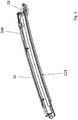
- einen schematische Längsschnitt durch eine Führungsschiene mit einem Ausschlauffreischnitt; und
- Figur 8
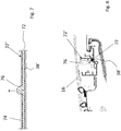
- einen Querschnitt durch die Führungsschiene im Bereich des Ausschlauffreischnitts.
- In
Figur 1 ist ein Dach 10 eines als Personenkraftwagen ausgebildeten Kraftfahrzeugs dargestellt. Das Dach 10 umfasst einen Festdachabschnitt 12, in welchem eine Dachöffnung 14 ausgebildet ist, welche mittels eines Schiebedachdeckels 16 eines Dachöffnungssystems 18 wahlweise geschlossen oder zumindest teilweise freigegeben werden kann. - Der Schiebedachdeckel 16 des Dachöffnungssystems 18 ist bezogen auf eine vertikale Dachlängsmittelebene beidseits jeweils mit einer Verstellkinematik 20A bzw. 20B versehen, die in einer jeweiligen Führungsschiene 22A bzw. 22B geführt ist, die sich in Dach- bzw. Fahrzeuglängsrichtung erstreckt und entlang des jeweiligen seitlichen Randes der Dachöffnung 14 angeordnet ist.
- Die Führungsschienen 22A und 22B sind Seitenholme eines Dachrahmens 24 und an ihren bugseitigen Enden über ein Rahmenvorderteil 26 miteinander verbunden, das ein sich in Dachquerrichtung erstreckendes Rahmenquerteil des Dachrahmens 24 bildet. Der Dachrahmen 24 ist bezogen auf eine vertikale Dachlängsmittelebene im Wesentlichen spiegelsymmetrisch ausgebildet, weswegen der Übersichtlichkeit halber die nachfolgende Beschreibung im Wesentlichen nur anhand der bezogen auf die Vorwärtsfahrtrichtung des betreffenden Fahrzeugs links angeordneten Führungsschiene 22B erfolgt. Die bezogen auf die Vorwärtsfahrtrichtung des betreffenden Fahrzeugs rechts angeordnete Führungsschiene 22A ergibt sich in analoger Weise aus der Beschreibung.
- Wie den
Figuren 2 und3 zu entnehmen ist, hat die Führungsschiene 22B in ihrem Übergangsbereich zu dem Rahmenvorderteil 26 ein Endstück 28, welches in denFiguren 4 bis 6 in Alleinstellung dargestellt ist. Das Endstück 28, das als Spritzgieß-Kunststoffformteil ausgebildet ist, umfasst eine Anhebekulisse 30, in welcher beim Verstellen des Schiebedachdeckels 16 aus der Schließstellung in die Öffnungsstellung ein Gleiter geführt ist, so dass ein vorderer Rand des Schiebedachdeckels 16 gegenüber dem Festdachabschnitt 12 angehoben werden kann. Zur Fixierung des ein Kulissenteil darstellenden Endstücks 28 an einem Führungsabschnitt 32 der Führungsschiene 22B, der als Strangpressprofil aus Aluminium gefertigt ist, umfasst das Endstück 28 Rast- und Positionierlaschen 34. Um die Führungsschiene 22B mit dem Rahmenvorderteil 26 verbinden zu können, weist das Endstück 28 Schraubenöffnungen 36 auf. - Zum Antrieb der Verstellkinematiken 20A und 20B weist das Dachöffnungssystem 18 Antriebskabel 38A und 38B auf, welche mittels eines gemeinsamen Antriebsmotors 40 bzw. eines Ritzels desselben angetrieben sind. Die Antriebskabel 38A und 38B sind jeweils über eine Kabelführung in dem Rahmenvorderteil 26 in einen Kabelkanal 42 der Endstücke 28 und von dort in korrespondierende Kabelkanäle der Führungsabschnitte 32 der Führungsschienen 22A und 22B geführt und in den Führungsschienen 22A und 22B jeweils mit einem nicht näher dargestellten Antriebsschlitten der jeweiligen Verstellkinematik 20A bzw. 20B verbunden.
- Durch die Ausbildung des Kabelkanals 42 stellt das Endstück 28, das nach einem Spritzgießprozess hergestellt ist, ein Kabelführungselement dar. Neben dem Kabelkanal 42 ist in dem Endstück zudem ein zweiter Kabelkanal 44 ausgebildet, welcher zur Führung eines Antriebskabels eines Beschattungssystems des Daches 10 dient.
- Der Kabelkanal 42 stellt eine alternierende Kabelführung dar, welche durch erste Wandabschnitte 46 und 48, die den Kabelkanal 42 von einer ersten Seite begrenzen, und zweiten Wandabschnitten 50 gebildet, die den Kabelkanal 42 von einer zweiten Seite begrenzen. Dies führt dazu, dass das Antriebskabel 38B wechselweise von der ersten Seite mittels der ersten Wandabschnitte 46, 48 und von einer zweiten Seite mittels der zweiten Wandabschnitte 50 geführt ist. Die ersten Wandabschnitte 46 und 48 sind jeweils durch einen ersten Freischnitt 52 getrennt, der einem jeweiligen zweiten Wandabschnitt 50 gegenüberliegt. Die zweiten Wandabschnitte 50 sind jeweils durch einen zweiten Freischnitt 54 getrennt, der einem jeweiligen ersten Wandabschnitt 48 gegenüberliegt. Dem ersten Wandabschnitt 46 liegt ein Freischnitt 55 gegenüber, der einen zweiten Wandabschnitt 50 begrenzt.
- Der Freischnitt 55, der dem ersten Wandabschnitt 46 gegenüberliegt, hat eine Länge von etwa 9 mm. Die restlichen Freischnitte 52 und 54 haben in Längsrichtung des Kabelkanals 42 eine Länge von weniger als 8 mm. Damit hat der Freischnitt 54, der dem ersten Wandabschnitt 46 gegenüberliegt, eine Länge, die geringer ist als eine kritische Ausschlauflänge von etwa 10 mm, ab der das Antriebskabel 38B im Wesentlichen ungebremst durch den Freischnitt 54 ausschlaufen könnte. Gleichzeitig hat der dem ersten Wandabschnitt 46 gegenüberliegende Freischnitt 55 eine Länge, die geringer ist als eine Ausschlaufgrenzlänge von etwa 8,0 mm, unterhalb derer ein Ausschlaufen des Antriebskabels 38B in der in
Figur 6 gestrichelt dargestellten Weise im Wesentlichen ausgeschlossen ist. - Das Antriebskabel 38B, das als drucksteifes Steigungskabel ausgebildet sein kann, hat einen Durchmesser von etwa 5,3 mm, der mit dem Durchmesser des Kabelkanals 42 korrespondiert, so dass auch der Kabelkanal 42 bei einer Projektion entlang der Kabelkanallängsachse einen Durchmesser von etwa 5,3 mm hat.
- Bei einem Ausschlaufen des Kabelkanals 22B durch den dem ersten Wandabschnitt 46 gegenüberliegenden, einen Ausschlauffreischnitt bildenden Freischnitt 55 in der in
Figur 6 dargestellten Weise, wird der ausschlaufende Teil des Antriebskabels 22B durch einen sich an den Freischnitt 55 anschließenden Dämpftrichter 56 gebremst, der durch aufeinander zulaufende Flächen 58 und 60 des Endstücks 28 gebildet ist. Damit kann erreicht werden, dass eine definierte Gegenkraft auf das Antriebskabel 38B ausgeübt wird, welche mit zunehmendem Ausschlaufen des Antriebskabels 38B durch den Freischnitt 55 steigt. Durch das so erfolgende gezielte Ausschlaufen des Antriebskabels 38B in den taschenartigen Dämpftrichter wird im Falle einer Kollision des betreffenden Fahrzeugs kinematische Energie, die von dem hierdurch beschleunigten Schiebedachdeckel 16 auf das Antriebskabel 38B übertragen wird, kontinuierlich abgebaut. Bei Erreichen eines bestimmten Ausschlaufbetrags erfolgt durch den Dämpftrichter 56 ein Blockieren des Antriebskabels 38B, wodurch auch ein weiteres Verfahren des insbesondere als Glasdeckel ausgebildeten Schiebedachdeckels gesperrt ist. Durch das Ausschlaufen des Antriebskabels 38B können andere Bauteile des Dachöffnungssystems 18, insbesondere auch die Wandabschnitte 46, 48 und 50 des Kabelkanals 42 vor einer Überlastung und damit vor einer Beschädigung geschützt werden. Die von dem Dämpftrichter 56 ausgeübte Gegenkraft sollte stets unter der Kraft liegen, ab der das Risiko einer Beschädigung der Verstellkinematik vorliegt. - Der Kabelkanal 44 kann entsprechend dem Kabelkanal 42 ausgebildet sein.
- In den
Figuren 7 und 8 ist eine alternative Ausführungsform des Gegenstandes der Erfindung dargestellt. Diese Ausführungsform umfasst eine Führungsschiene 22', die entsprechend der Ausführungsform nach denFiguren 1 bis 6 einen Längsholm eines Dachrahmens darstellt, der Bestandteil eines Dachöffnungssystems der inFigur 1 dargestellten Art ist. Die Führungsschiene 22' ist ein Aluminiumstrangpressprofil, in dem ein Kabelkanal 72 ausgebildet ist, welcher unter anderem von einer oberen, eine Kanalwand bildenden Rippe 74 begrenzt ist. In dem Kabelkanal 72 ist ein Antriebskabel 38' geführt, das hier als Steigungskabel mit einer Drahtumwicklung ausgebildet ist. - Die Rippe 74 hat in einem bugseitigen Abschnitt der Führungsschiene 22' eine Ausnehmung 76, welche einen Ausschlauffreischnitt für das Antriebskabel 38' darstellt und in Schienenlängsrichtung eine Länge von etwa 10 mm hat. Dies ist eine Länge, die größer ist als eine Ausschlaufgrenzlänge von 8 mm und geringer ist als eine kritische Ausschlauflänge von 10,5 mm.
- Wenn ein Schiebedachdeckel 16 eines Dachöffnungssystems 18, der mittels des Antriebskabels 38' angetrieben ist, sich in einer die betreffende Dachöffnung freigebenden Öffnungsstellung befindet, kann dieser in einer Unfallsituation eine starke Beschleunigung in Richtung Fahrzeugbug erfahren. Damit wirken über einen Anstriebsschlitten, der von dem Antriebskabel 38' angetrieben wird, hohe Kräfte auf eben dieses Antriebskabel 38'. Aufgrund des Ausschlauffreischnitts 76 kann das Antriebskabel 38' aber aus dem Kabelkanal 72 ausschlaufen, was zu einem kontinuierlichen Abbau der kinetischen Energie des Schiebedachdeckels 16 führt. Der Schiebedachdeckel 16 kommt zum Stehen, wenn der Antriebsschlitten die Position des Ausschlauffreischnitts bzw. der Ausnehmung 76 erreicht hat.
-
- 10
- Dach
- 12
- Festdachabschnitt
- 14
- Dachöffnung
- 16
- Schiebedachdeckel
- 18
- Dachöffnungsystem
- 20A, B
- Verstellkinematik
- 22A, B
- Führungsschiene
- 22'
- Führungsschiene
- 24
- Dachrahmen
- 26
- Rahmenvorderteil
- 28
- Endstück
- 30
- Anhebekulisse
- 32
- Führungsabschnitt
- 34
- Rast- uns Positionslasche
- 36
- Schraubenöffnung
- 38A, B
- Antriebskabel
- 38'
- Antriebskabel
- 40
- Antriebsmotor
- 42
- Kabelkanal
- 44
- Kabelkanal
- 46
- erster Wandabschnitt
- 48
- erster Wandabschnitt
- 50
- zweiter Wandabschnitt
- 52
- erster Freischnitt
- 54
- zweiter Freischnitt
- 55
- Freischnitt
- 56
- Dämpftrichter
- 58
- Fläche
- 60
- Fläche
- 72
- Kabelkanal
- 74
- Rippe
- 76
- Ausnehmung
Claims (10)
- Rahmen eines Fahrzeugdachs, umfassend ein Kabelführungselement, in dem ein Kabelkanal (42, 72) zur Aufnahme eines Antriebskabels (38A, 38B) für ein verstellbares Dachelement ausgebildet ist, der von einer Kanalwand begrenzt ist, wobei die Kanalwand einen Ausschlauffreischnitt hat, der in Längsrichtung des Kabelkanals (42) eine Länge hat, die größer ist als eine Ausschlaufgrenzlänge, dadurch gekennzeichnet, dass der Ausschlauffreischnitt (55) eine Länge in Längsrichtung des Kabelkanals (42, 72) hat, die geringer ist als eine kritische Ausschlauflänge die etwa 9,5 mm bis 10,5 mm beträgt, wobei die Ausschlaufgrenzlänge etwa 7,5 mm bis 8,5mm beträgt.
- Rahmen nach Anspruch 1, dadurch gekennzeichnet, dass die kritische Ausschlauflänge etwa 10 mm beträgt.
- Rahmen nach einem der Ansprüche 1 oder 2, dadurch gekennzeichnet, dass die Ausschlaufgrenzlänge etwa 8,0 mm beträgt.
- Rahmen nach einem der Ansprüche 1 bis 3, dadurch gekennzeichnet, dass der Kabellkanal (42, 72) bei einer Projektion entlang der Kabelkanalachse einen Durchmesser von etwa 5,0 mm bis 5,5 mm hat.
- Rahmen nach einem der Ansprüche 1 bis 4, dadurch gekennzeichnet, dass sich an den Ausschlauffreischnitt (55) ein Dämpftrichter (56) anschließt, dessen Querschnittsfläche sich ausgehend von dem Ausschlauffreischnitt (52) verkleinert.
- Rahmen nach einem der Ansprüche 1 bis 5, dadurch gekennzeichnet, dass das Kabelführungselement eine Führungsschiene (22'), in der eine Antriebsmechanik eines Dachöffnungssystems geführt ist, ein an eine Führungsschiene angebundenes Kulissenelement, ein Rahmenquerteil, insbesondere ein Rahmenvorderteil oder ein Rahmenhinterteil, ein Rahmenlängsteil oder ein in den Rahmen integriertes Führungsrohr ist.
- Rahmen nach einem der Ansprüche 1 bis 6, dadurch gekennzeichnet, dass das Kabelführungselement ein Kunststoffformteil ist, in dem der Kabelkanal (42) zur Aufnahme des Antriebskabels (38A, 38B) für das verstellbare Dachelement ausgebildet ist, wobei der Kabelkanal (42) das Antriebskabel (38A, 38B) wechselweise von einer ersten Seite mittels erster Wandabschnitte (46, 48) und von einer zweiten Seite mittels zweiter Wandabschnitte (50) führt und die ersten Wandabschnitte (46, 48) und die zweiten Wandabschnitte (50) die Kanalwand bilden, wobei die ersten Wandabschnitte (46, 48) jeweils an mindestens einen ersten Freischnitt (52) grenzen, der einem jeweiligen zweiten Wandabschnitt (50) gegenüberliegt, und die zweiten Wandabschnitte (50) jeweils an mindestens einen zweiten Freischnitt (55) grenzen, der einem jeweiligen ersten Wandabschnitt (46, 48) gegenüberliegt, und einer der Freischnitte (55) der Ausschlauffreischnitt ist, der in Längsrichtung des Kabelkanals (42) eine Länge hat, die größer ist als eine Ausschlaufgrenzlänge, und die anderen Freischnitte (52, 54) in Längsrichtung des Kabelkanals (42) eine Länge haben, die unterhalb der Ausschlaufgrenzlänge liegt.
- Rahmen nach Anspruch 6, dadurch gekennzeichnet, dass die Führungsschiene (32) ein Strangpressprofil ist, in dem der Kabelkanal (72) ausgebildet ist, wobei die Kanalwand mit dem Auschlauffreischnitt von einer sich in Führungsschienenlängsrichtung erstreckenden Rippe (74) der Führungsschiene (22') gebildet ist und der Ausschlauffreischnitt durch eine Ausnehmung (76) der Rippe (74) gebildet ist.
- Rahmen nach Anspruch 8, dadurch gekennzeichnet, dass die Ausnehmung (76) im Bereich einer bugseitigen Hälfte, insbesondere eines bugseitigen Drittels der Führungsschiene (22') angeordnet ist.
- Rahmen nach Anspruch 8 oder 9, dadurch gekennzeichnet, dass die Führungsschiene (22') aus Aluminium gefertigt ist.
Applications Claiming Priority (3)
| Application Number | Priority Date | Filing Date | Title |
|---|---|---|---|
| DE102017128133 | 2017-11-28 | ||
| DE102018112725.1A DE102018112725A1 (de) | 2017-11-28 | 2018-05-28 | Rahmen eines Fahrzeugdachs mit Kabelführungselement |
| PCT/EP2018/078958 WO2019105653A1 (de) | 2017-11-28 | 2018-10-23 | Rahmen eines fahrzeugdachs mit kabelführungselement |
Publications (2)
| Publication Number | Publication Date |
|---|---|
| EP3565727A1 EP3565727A1 (de) | 2019-11-13 |
| EP3565727B1 true EP3565727B1 (de) | 2021-04-07 |
Family
ID=66442438
Family Applications (1)
| Application Number | Title | Priority Date | Filing Date |
|---|---|---|---|
| EP18796859.9A Active EP3565727B1 (de) | 2017-11-28 | 2018-10-23 | Rahmen eines fahrzeugdachs mit kabelführungselement |
Country Status (5)
| Country | Link |
|---|---|
| US (1) | US11040604B2 (de) |
| EP (1) | EP3565727B1 (de) |
| CN (1) | CN110520319B (de) |
| DE (1) | DE102018112725A1 (de) |
| WO (1) | WO2019105653A1 (de) |
Families Citing this family (2)
| Publication number | Priority date | Publication date | Assignee | Title |
|---|---|---|---|---|
| DE102023121371A1 (de) * | 2023-08-10 | 2025-02-13 | Webasto SE | Fahrzeugdach mit Dachaußenhautelement und Innenhimmel |
| JP7808668B1 (ja) * | 2024-11-08 | 2026-01-29 | マザーサンヤチヨ・オートモーティブシステムズ株式会社 | サンルーフフレーム |
Family Cites Families (10)
| Publication number | Priority date | Publication date | Assignee | Title |
|---|---|---|---|---|
| JPH0653236U (ja) | 1990-12-28 | 1994-07-19 | アイシン精機株式会社 | サンルーフのガイドレール |
| DE4422646C1 (de) * | 1994-06-28 | 1995-08-03 | Webasto Karosseriesysteme | Rahmen für Fahrzeugdächer |
| DE10219965B4 (de) * | 2002-05-03 | 2004-06-03 | Webasto Vehicle Systems International Gmbh | Führungsschiene für einen Mitnehmer |
| US6582014B1 (en) * | 2002-07-22 | 2003-06-24 | Webasto Sunroofs, Inc. | Sunroof mechanism and a rail assembly for the same |
| CN100467300C (zh) * | 2003-04-10 | 2009-03-11 | 安托林-工程集团股份有限公司 | 机动车辆天窗的支撑框架 |
| CN101680911B (zh) * | 2007-05-07 | 2014-06-18 | 英泰斯特股份有限公司 | 测试头操作器的支架与缆线保持器 |
| EP2072303B1 (de) | 2007-12-18 | 2012-06-13 | Advanced Comfort Systems France SAS - ACS France | Sonnenschutz für mindestens eine Glasfläche eines Kraftfahrzeugdachs, sowie entsprechendes Kraftfahrzeug und Befestigungselement |
| EP2425997B1 (de) * | 2010-09-01 | 2013-04-24 | Inalfa Roof Systems Group B.V. | Dachanordnung für ein Fahrzeug |
| DE102013210470B4 (de) * | 2013-06-05 | 2017-11-02 | Bos Gmbh & Co. Kg | Antriebsübertragungssystem und Verfahren zur Montage eines derartigen Antriebsübertragungssystems |
| EP2826651B1 (de) | 2013-07-16 | 2016-11-02 | Webasto SE | Rahmen eines Fahrzeugschiebedachs mit Kabelkanälen |
-
2018
- 2018-05-28 DE DE102018112725.1A patent/DE102018112725A1/de not_active Withdrawn
- 2018-10-23 EP EP18796859.9A patent/EP3565727B1/de active Active
- 2018-10-23 WO PCT/EP2018/078958 patent/WO2019105653A1/de not_active Ceased
- 2018-10-23 CN CN201880021389.4A patent/CN110520319B/zh active Active
- 2018-10-23 US US16/485,301 patent/US11040604B2/en active Active
Non-Patent Citations (1)
| Title |
|---|
| None * |
Also Published As
| Publication number | Publication date |
|---|---|
| WO2019105653A1 (de) | 2019-06-06 |
| US20200016964A1 (en) | 2020-01-16 |
| DE102018112725A1 (de) | 2019-05-29 |
| CN110520319B (zh) | 2023-05-09 |
| EP3565727A1 (de) | 2019-11-13 |
| US11040604B2 (en) | 2021-06-22 |
| CN110520319A (zh) | 2019-11-29 |
Similar Documents
| Publication | Publication Date | Title |
|---|---|---|
| DE69925359T3 (de) | Schiebedach für fahrzeuge | |
| DE29507916U1 (de) | Schubkastenauszugsführung | |
| EP1275541B1 (de) | Modul, insbesondere Schiebedachmodul für ein Fahrzeug | |
| EP2285608B1 (de) | Fahrzeugdach mit aussen laufendem schiebedach | |
| DE102015225811A1 (de) | Dachsystem für ein Kraftfahrzeug | |
| WO2014082920A2 (de) | Dachsystem für ein kraftfahrzeug | |
| EP3565727B1 (de) | Rahmen eines fahrzeugdachs mit kabelführungselement | |
| DE19704444C1 (de) | Greifvorrichtung | |
| EP3138711B1 (de) | Dachsystem für ein kraftfahrzeug | |
| DE102015119405A1 (de) | Schiebedachmodul und Verfahren zur Herstellung des Schiebedachmoduls | |
| DE102018124382A1 (de) | Fahrzeugdach mit Dachöffnungssystem und Antriebseinrichtung für Kinematikeinheiten | |
| EP3347222B1 (de) | Fahrzeugdach mit einem beweglichen dachteil | |
| EP1577136A2 (de) | Schiebedachsystem | |
| DE102007001286B4 (de) | Öffenbares Fahrzeugdach mit Antriebsschlitten für ein Dachelement | |
| DE102019215548A1 (de) | Antriebssystem für ein bewegliches Dachteil eines Dachsystems eines Kraftfahrzeugs | |
| DE112019006626B4 (de) | Antriebssystem für ein bewegliches Dachteil eines Dachmoduls eines Kraftfahrzeugs | |
| EP2826652A1 (de) | Rahmen eines Fahrzeugschiebedachs mit Kabelkanälen | |
| DE202018100220U1 (de) | Rollosystem für ein Fahrzeugdach | |
| DE102018112217A1 (de) | Fahrzeugdachrahmen mit Antriebsrohr für Antriebskabel | |
| EP3870788B1 (de) | Fensterhebersystem und kraftfahrzeugtür | |
| DE102017121939A1 (de) | Fahrzeugdachrahmen mit Kabelkanal und Verfahren zu dessen Herstellung | |
| DE102007003354B4 (de) | Fahrzeugdach mit einem oberhalb des Daches verschiebbaren Dachteil | |
| EP1902885B1 (de) | Schiebedachsystem | |
| EP3408119B1 (de) | Kraftfahrzeug mit gegenüber fahrzeugaufbau verstellbarem fahrzeugteil | |
| DE10151619C2 (de) | Vorrichtung zum Öffnen und Schließen einer Öffnung in einem Fahrzeugdach mit einem Deckel |
Legal Events
| Date | Code | Title | Description |
|---|---|---|---|
| STAA | Information on the status of an ep patent application or granted ep patent |
Free format text: STATUS: UNKNOWN |
|
| STAA | Information on the status of an ep patent application or granted ep patent |
Free format text: STATUS: THE INTERNATIONAL PUBLICATION HAS BEEN MADE |
|
| PUAI | Public reference made under article 153(3) epc to a published international application that has entered the european phase |
Free format text: ORIGINAL CODE: 0009012 |
|
| STAA | Information on the status of an ep patent application or granted ep patent |
Free format text: STATUS: REQUEST FOR EXAMINATION WAS MADE |
|
| 17P | Request for examination filed |
Effective date: 20190807 |
|
| AK | Designated contracting states |
Kind code of ref document: A1 Designated state(s): AL AT BE BG CH CY CZ DE DK EE ES FI FR GB GR HR HU IE IS IT LI LT LU LV MC MK MT NL NO PL PT RO RS SE SI SK SM TR |
|
| AX | Request for extension of the european patent |
Extension state: BA ME |
|
| GRAP | Despatch of communication of intention to grant a patent |
Free format text: ORIGINAL CODE: EPIDOSNIGR1 |
|
| STAA | Information on the status of an ep patent application or granted ep patent |
Free format text: STATUS: GRANT OF PATENT IS INTENDED |
|
| DAV | Request for validation of the european patent (deleted) | ||
| DAX | Request for extension of the european patent (deleted) | ||
| INTG | Intention to grant announced |
Effective date: 20200909 |
|
| GRAJ | Information related to disapproval of communication of intention to grant by the applicant or resumption of examination proceedings by the epo deleted |
Free format text: ORIGINAL CODE: EPIDOSDIGR1 |
|
| STAA | Information on the status of an ep patent application or granted ep patent |
Free format text: STATUS: REQUEST FOR EXAMINATION WAS MADE |
|
| GRAS | Grant fee paid |
Free format text: ORIGINAL CODE: EPIDOSNIGR3 |
|
| STAA | Information on the status of an ep patent application or granted ep patent |
Free format text: STATUS: GRANT OF PATENT IS INTENDED |
|
| GRAP | Despatch of communication of intention to grant a patent |
Free format text: ORIGINAL CODE: EPIDOSNIGR1 |
|
| INTC | Intention to grant announced (deleted) | ||
| INTG | Intention to grant announced |
Effective date: 20210201 |
|
| GRAA | (expected) grant |
Free format text: ORIGINAL CODE: 0009210 |
|
| STAA | Information on the status of an ep patent application or granted ep patent |
Free format text: STATUS: THE PATENT HAS BEEN GRANTED |
|
| AK | Designated contracting states |
Kind code of ref document: B1 Designated state(s): AL AT BE BG CH CY CZ DE DK EE ES FI FR GB GR HR HU IE IS IT LI LT LU LV MC MK MT NL NO PL PT RO RS SE SI SK SM TR |
|
| REG | Reference to a national code |
Ref country code: GB Ref legal event code: FG4D Free format text: NOT ENGLISH |
|
| REG | Reference to a national code |
Ref country code: AT Ref legal event code: REF Ref document number: 1379234 Country of ref document: AT Kind code of ref document: T Effective date: 20210415 Ref country code: CH Ref legal event code: EP |
|
| REG | Reference to a national code |
Ref country code: DE Ref legal event code: R096 Ref document number: 502018004742 Country of ref document: DE |
|
| REG | Reference to a national code |
Ref country code: IE Ref legal event code: FG4D Free format text: LANGUAGE OF EP DOCUMENT: GERMAN |
|
| REG | Reference to a national code |
Ref country code: LT Ref legal event code: MG9D |
|
| REG | Reference to a national code |
Ref country code: NL Ref legal event code: MP Effective date: 20210407 |
|
| PG25 | Lapsed in a contracting state [announced via postgrant information from national office to epo] |
Ref country code: LT Free format text: LAPSE BECAUSE OF FAILURE TO SUBMIT A TRANSLATION OF THE DESCRIPTION OR TO PAY THE FEE WITHIN THE PRESCRIBED TIME-LIMIT Effective date: 20210407 Ref country code: HR Free format text: LAPSE BECAUSE OF FAILURE TO SUBMIT A TRANSLATION OF THE DESCRIPTION OR TO PAY THE FEE WITHIN THE PRESCRIBED TIME-LIMIT Effective date: 20210407 Ref country code: FI Free format text: LAPSE BECAUSE OF FAILURE TO SUBMIT A TRANSLATION OF THE DESCRIPTION OR TO PAY THE FEE WITHIN THE PRESCRIBED TIME-LIMIT Effective date: 20210407 Ref country code: NL Free format text: LAPSE BECAUSE OF FAILURE TO SUBMIT A TRANSLATION OF THE DESCRIPTION OR TO PAY THE FEE WITHIN THE PRESCRIBED TIME-LIMIT Effective date: 20210407 Ref country code: BG Free format text: LAPSE BECAUSE OF FAILURE TO SUBMIT A TRANSLATION OF THE DESCRIPTION OR TO PAY THE FEE WITHIN THE PRESCRIBED TIME-LIMIT Effective date: 20210707 |
|
| PG25 | Lapsed in a contracting state [announced via postgrant information from national office to epo] |
Ref country code: SE Free format text: LAPSE BECAUSE OF FAILURE TO SUBMIT A TRANSLATION OF THE DESCRIPTION OR TO PAY THE FEE WITHIN THE PRESCRIBED TIME-LIMIT Effective date: 20210407 Ref country code: RS Free format text: LAPSE BECAUSE OF FAILURE TO SUBMIT A TRANSLATION OF THE DESCRIPTION OR TO PAY THE FEE WITHIN THE PRESCRIBED TIME-LIMIT Effective date: 20210407 Ref country code: PT Free format text: LAPSE BECAUSE OF FAILURE TO SUBMIT A TRANSLATION OF THE DESCRIPTION OR TO PAY THE FEE WITHIN THE PRESCRIBED TIME-LIMIT Effective date: 20210809 Ref country code: PL Free format text: LAPSE BECAUSE OF FAILURE TO SUBMIT A TRANSLATION OF THE DESCRIPTION OR TO PAY THE FEE WITHIN THE PRESCRIBED TIME-LIMIT Effective date: 20210407 Ref country code: LV Free format text: LAPSE BECAUSE OF FAILURE TO SUBMIT A TRANSLATION OF THE DESCRIPTION OR TO PAY THE FEE WITHIN THE PRESCRIBED TIME-LIMIT Effective date: 20210407 Ref country code: NO Free format text: LAPSE BECAUSE OF FAILURE TO SUBMIT A TRANSLATION OF THE DESCRIPTION OR TO PAY THE FEE WITHIN THE PRESCRIBED TIME-LIMIT Effective date: 20210707 Ref country code: IS Free format text: LAPSE BECAUSE OF FAILURE TO SUBMIT A TRANSLATION OF THE DESCRIPTION OR TO PAY THE FEE WITHIN THE PRESCRIBED TIME-LIMIT Effective date: 20210807 Ref country code: GR Free format text: LAPSE BECAUSE OF FAILURE TO SUBMIT A TRANSLATION OF THE DESCRIPTION OR TO PAY THE FEE WITHIN THE PRESCRIBED TIME-LIMIT Effective date: 20210708 |
|
| REG | Reference to a national code |
Ref country code: DE Ref legal event code: R097 Ref document number: 502018004742 Country of ref document: DE |
|
| PG25 | Lapsed in a contracting state [announced via postgrant information from national office to epo] |
Ref country code: SK Free format text: LAPSE BECAUSE OF FAILURE TO SUBMIT A TRANSLATION OF THE DESCRIPTION OR TO PAY THE FEE WITHIN THE PRESCRIBED TIME-LIMIT Effective date: 20210407 Ref country code: ES Free format text: LAPSE BECAUSE OF FAILURE TO SUBMIT A TRANSLATION OF THE DESCRIPTION OR TO PAY THE FEE WITHIN THE PRESCRIBED TIME-LIMIT Effective date: 20210407 Ref country code: EE Free format text: LAPSE BECAUSE OF FAILURE TO SUBMIT A TRANSLATION OF THE DESCRIPTION OR TO PAY THE FEE WITHIN THE PRESCRIBED TIME-LIMIT Effective date: 20210407 Ref country code: CZ Free format text: LAPSE BECAUSE OF FAILURE TO SUBMIT A TRANSLATION OF THE DESCRIPTION OR TO PAY THE FEE WITHIN THE PRESCRIBED TIME-LIMIT Effective date: 20210407 Ref country code: DK Free format text: LAPSE BECAUSE OF FAILURE TO SUBMIT A TRANSLATION OF THE DESCRIPTION OR TO PAY THE FEE WITHIN THE PRESCRIBED TIME-LIMIT Effective date: 20210407 Ref country code: RO Free format text: LAPSE BECAUSE OF FAILURE TO SUBMIT A TRANSLATION OF THE DESCRIPTION OR TO PAY THE FEE WITHIN THE PRESCRIBED TIME-LIMIT Effective date: 20210407 Ref country code: SM Free format text: LAPSE BECAUSE OF FAILURE TO SUBMIT A TRANSLATION OF THE DESCRIPTION OR TO PAY THE FEE WITHIN THE PRESCRIBED TIME-LIMIT Effective date: 20210407 |
|
| PLBE | No opposition filed within time limit |
Free format text: ORIGINAL CODE: 0009261 |
|
| STAA | Information on the status of an ep patent application or granted ep patent |
Free format text: STATUS: NO OPPOSITION FILED WITHIN TIME LIMIT |
|
| 26N | No opposition filed |
Effective date: 20220110 |
|
| REG | Reference to a national code |
Ref country code: CH Ref legal event code: PL |
|
| PG25 | Lapsed in a contracting state [announced via postgrant information from national office to epo] |
Ref country code: IS Free format text: LAPSE BECAUSE OF FAILURE TO SUBMIT A TRANSLATION OF THE DESCRIPTION OR TO PAY THE FEE WITHIN THE PRESCRIBED TIME-LIMIT Effective date: 20210807 Ref country code: AL Free format text: LAPSE BECAUSE OF FAILURE TO SUBMIT A TRANSLATION OF THE DESCRIPTION OR TO PAY THE FEE WITHIN THE PRESCRIBED TIME-LIMIT Effective date: 20210407 |
|
| REG | Reference to a national code |
Ref country code: BE Ref legal event code: MM Effective date: 20211031 |
|
| PG25 | Lapsed in a contracting state [announced via postgrant information from national office to epo] |
Ref country code: MC Free format text: LAPSE BECAUSE OF FAILURE TO SUBMIT A TRANSLATION OF THE DESCRIPTION OR TO PAY THE FEE WITHIN THE PRESCRIBED TIME-LIMIT Effective date: 20210407 |
|
| PG25 | Lapsed in a contracting state [announced via postgrant information from national office to epo] |
Ref country code: LU Free format text: LAPSE BECAUSE OF NON-PAYMENT OF DUE FEES Effective date: 20211023 Ref country code: IT Free format text: LAPSE BECAUSE OF FAILURE TO SUBMIT A TRANSLATION OF THE DESCRIPTION OR TO PAY THE FEE WITHIN THE PRESCRIBED TIME-LIMIT Effective date: 20210407 Ref country code: BE Free format text: LAPSE BECAUSE OF NON-PAYMENT OF DUE FEES Effective date: 20211031 |
|
| PG25 | Lapsed in a contracting state [announced via postgrant information from national office to epo] |
Ref country code: LI Free format text: LAPSE BECAUSE OF NON-PAYMENT OF DUE FEES Effective date: 20211031 Ref country code: CH Free format text: LAPSE BECAUSE OF NON-PAYMENT OF DUE FEES Effective date: 20211031 |
|
| PG25 | Lapsed in a contracting state [announced via postgrant information from national office to epo] |
Ref country code: IE Free format text: LAPSE BECAUSE OF NON-PAYMENT OF DUE FEES Effective date: 20211023 |
|
| PG25 | Lapsed in a contracting state [announced via postgrant information from national office to epo] |
Ref country code: CY Free format text: LAPSE BECAUSE OF FAILURE TO SUBMIT A TRANSLATION OF THE DESCRIPTION OR TO PAY THE FEE WITHIN THE PRESCRIBED TIME-LIMIT Effective date: 20210407 |
|
| PG25 | Lapsed in a contracting state [announced via postgrant information from national office to epo] |
Ref country code: HU Free format text: LAPSE BECAUSE OF FAILURE TO SUBMIT A TRANSLATION OF THE DESCRIPTION OR TO PAY THE FEE WITHIN THE PRESCRIBED TIME-LIMIT; INVALID AB INITIO Effective date: 20181023 |
|
| PG25 | Lapsed in a contracting state [announced via postgrant information from national office to epo] |
Ref country code: MK Free format text: LAPSE BECAUSE OF FAILURE TO SUBMIT A TRANSLATION OF THE DESCRIPTION OR TO PAY THE FEE WITHIN THE PRESCRIBED TIME-LIMIT Effective date: 20210407 |
|
| PG25 | Lapsed in a contracting state [announced via postgrant information from national office to epo] |
Ref country code: TR Free format text: LAPSE BECAUSE OF FAILURE TO SUBMIT A TRANSLATION OF THE DESCRIPTION OR TO PAY THE FEE WITHIN THE PRESCRIBED TIME-LIMIT Effective date: 20210407 |
|
| PG25 | Lapsed in a contracting state [announced via postgrant information from national office to epo] |
Ref country code: MT Free format text: LAPSE BECAUSE OF FAILURE TO SUBMIT A TRANSLATION OF THE DESCRIPTION OR TO PAY THE FEE WITHIN THE PRESCRIBED TIME-LIMIT Effective date: 20210407 |
|
| REG | Reference to a national code |
Ref country code: AT Ref legal event code: MM01 Ref document number: 1379234 Country of ref document: AT Kind code of ref document: T Effective date: 20231023 |
|
| PG25 | Lapsed in a contracting state [announced via postgrant information from national office to epo] |
Ref country code: AT Free format text: LAPSE BECAUSE OF NON-PAYMENT OF DUE FEES Effective date: 20231023 |
|
| PG25 | Lapsed in a contracting state [announced via postgrant information from national office to epo] |
Ref country code: AT Free format text: LAPSE BECAUSE OF NON-PAYMENT OF DUE FEES Effective date: 20231023 |
|
| PGFP | Annual fee paid to national office [announced via postgrant information from national office to epo] |
Ref country code: DE Payment date: 20251020 Year of fee payment: 8 |
|
| PGFP | Annual fee paid to national office [announced via postgrant information from national office to epo] |
Ref country code: GB Payment date: 20251024 Year of fee payment: 8 |
|
| PGFP | Annual fee paid to national office [announced via postgrant information from national office to epo] |
Ref country code: FR Payment date: 20251024 Year of fee payment: 8 |
|
| PGFP | Annual fee paid to national office [announced via postgrant information from national office to epo] |
Ref country code: AT Payment date: 20260410 Year of fee payment: 5 |