EP3565714B1 - A method for printing a 3d product and a 3d printing device - Google Patents
A method for printing a 3d product and a 3d printing device Download PDFInfo
- Publication number
- EP3565714B1 EP3565714B1 EP17818164.0A EP17818164A EP3565714B1 EP 3565714 B1 EP3565714 B1 EP 3565714B1 EP 17818164 A EP17818164 A EP 17818164A EP 3565714 B1 EP3565714 B1 EP 3565714B1
- Authority
- EP
- European Patent Office
- Prior art keywords
- printing
- virtual
- batch
- volume
- layer
- Prior art date
- Legal status (The legal status is an assumption and is not a legal conclusion. Google has not performed a legal analysis and makes no representation as to the accuracy of the status listed.)
- Active
Links
- 238000000034 method Methods 0.000 title claims description 160
- 238000007639 printing Methods 0.000 title claims description 43
- 239000000463 material Substances 0.000 claims description 87
- 230000008569 process Effects 0.000 claims description 85
- 238000010146 3D printing Methods 0.000 claims description 77
- 238000004519 manufacturing process Methods 0.000 claims description 66
- 239000000654 additive Substances 0.000 claims description 27
- 239000013590 bulk material Substances 0.000 claims description 26
- 230000000996 additive effect Effects 0.000 claims description 24
- 238000000638 solvent extraction Methods 0.000 claims description 23
- 239000002245 particle Substances 0.000 claims description 20
- 239000000853 adhesive Substances 0.000 claims description 16
- 230000001070 adhesive effect Effects 0.000 claims description 16
- 239000007767 bonding agent Substances 0.000 claims description 12
- 230000027455 binding Effects 0.000 claims description 10
- 238000004590 computer program Methods 0.000 claims description 5
- 238000001125 extrusion Methods 0.000 claims description 4
- 238000005192 partition Methods 0.000 claims description 4
- 230000000977 initiatory effect Effects 0.000 claims description 3
- 239000000047 product Substances 0.000 description 130
- 239000011230 binding agent Substances 0.000 description 53
- 239000002023 wood Substances 0.000 description 45
- 239000000843 powder Substances 0.000 description 41
- 239000011236 particulate material Substances 0.000 description 16
- 238000000151 deposition Methods 0.000 description 10
- 239000004566 building material Substances 0.000 description 8
- 239000003292 glue Substances 0.000 description 8
- 229920000642 polymer Polymers 0.000 description 7
- 239000003086 colorant Substances 0.000 description 6
- 229920003043 Cellulose fiber Polymers 0.000 description 5
- 239000003063 flame retardant Substances 0.000 description 5
- 230000003014 reinforcing effect Effects 0.000 description 5
- 239000000126 substance Substances 0.000 description 5
- XLYOFNOQVPJJNP-UHFFFAOYSA-N water Substances O XLYOFNOQVPJJNP-UHFFFAOYSA-N 0.000 description 5
- 230000008901 benefit Effects 0.000 description 4
- 230000008021 deposition Effects 0.000 description 4
- 238000006073 displacement reaction Methods 0.000 description 4
- 239000000835 fiber Substances 0.000 description 4
- 229910052751 metal Inorganic materials 0.000 description 4
- 239000002184 metal Substances 0.000 description 4
- 238000011282 treatment Methods 0.000 description 4
- 230000001427 coherent effect Effects 0.000 description 3
- WHHGLZMJPXIBIX-UHFFFAOYSA-N decabromodiphenyl ether Chemical compound BrC1=C(Br)C(Br)=C(Br)C(Br)=C1OC1=C(Br)C(Br)=C(Br)C(Br)=C1Br WHHGLZMJPXIBIX-UHFFFAOYSA-N 0.000 description 3
- 238000010586 diagram Methods 0.000 description 3
- 230000007613 environmental effect Effects 0.000 description 3
- 239000007788 liquid Substances 0.000 description 3
- 238000003754 machining Methods 0.000 description 3
- 238000002844 melting Methods 0.000 description 3
- 230000008018 melting Effects 0.000 description 3
- 150000002739 metals Chemical class 0.000 description 3
- -1 polyethylene Polymers 0.000 description 3
- 239000004814 polyurethane Substances 0.000 description 3
- 229920002635 polyurethane Polymers 0.000 description 3
- 235000002639 sodium chloride Nutrition 0.000 description 3
- OWICEWMBIBPFAH-UHFFFAOYSA-N (3-diphenoxyphosphoryloxyphenyl) diphenyl phosphate Chemical compound C=1C=CC=CC=1OP(OC=1C=C(OP(=O)(OC=2C=CC=CC=2)OC=2C=CC=CC=2)C=CC=1)(=O)OC1=CC=CC=C1 OWICEWMBIBPFAH-UHFFFAOYSA-N 0.000 description 2
- RNFJDJUURJAICM-UHFFFAOYSA-N 2,2,4,4,6,6-hexaphenoxy-1,3,5-triaza-2$l^{5},4$l^{5},6$l^{5}-triphosphacyclohexa-1,3,5-triene Chemical compound N=1P(OC=2C=CC=CC=2)(OC=2C=CC=CC=2)=NP(OC=2C=CC=CC=2)(OC=2C=CC=CC=2)=NP=1(OC=1C=CC=CC=1)OC1=CC=CC=C1 RNFJDJUURJAICM-UHFFFAOYSA-N 0.000 description 2
- VEORPZCZECFIRK-UHFFFAOYSA-N 3,3',5,5'-tetrabromobisphenol A Chemical compound C=1C(Br)=C(O)C(Br)=CC=1C(C)(C)C1=CC(Br)=C(O)C(Br)=C1 VEORPZCZECFIRK-UHFFFAOYSA-N 0.000 description 2
- 239000004593 Epoxy Substances 0.000 description 2
- 239000004831 Hot glue Substances 0.000 description 2
- XEEYBQQBJWHFJM-UHFFFAOYSA-N Iron Chemical compound [Fe] XEEYBQQBJWHFJM-UHFFFAOYSA-N 0.000 description 2
- UQSXHKLRYXJYBZ-UHFFFAOYSA-N Iron oxide Chemical compound [Fe]=O UQSXHKLRYXJYBZ-UHFFFAOYSA-N 0.000 description 2
- TWRXJAOTZQYOKJ-UHFFFAOYSA-L Magnesium chloride Chemical compound [Mg+2].[Cl-].[Cl-] TWRXJAOTZQYOKJ-UHFFFAOYSA-L 0.000 description 2
- CSNNHWWHGAXBCP-UHFFFAOYSA-L Magnesium sulfate Chemical compound [Mg+2].[O-][S+2]([O-])([O-])[O-] CSNNHWWHGAXBCP-UHFFFAOYSA-L 0.000 description 2
- 239000004677 Nylon Substances 0.000 description 2
- OAICVXFJPJFONN-UHFFFAOYSA-N Phosphorus Chemical compound [P] OAICVXFJPJFONN-UHFFFAOYSA-N 0.000 description 2
- 239000004793 Polystyrene Substances 0.000 description 2
- WCUXLLCKKVVCTQ-UHFFFAOYSA-M Potassium chloride Chemical compound [Cl-].[K+] WCUXLLCKKVVCTQ-UHFFFAOYSA-M 0.000 description 2
- 229920000297 Rayon Polymers 0.000 description 2
- VYPSYNLAJGMNEJ-UHFFFAOYSA-N Silicium dioxide Chemical compound O=[Si]=O VYPSYNLAJGMNEJ-UHFFFAOYSA-N 0.000 description 2
- CDBYLPFSWZWCQE-UHFFFAOYSA-L Sodium Carbonate Chemical compound [Na+].[Na+].[O-]C([O-])=O CDBYLPFSWZWCQE-UHFFFAOYSA-L 0.000 description 2
- FAPWRFPIFSIZLT-UHFFFAOYSA-M Sodium chloride Chemical compound [Na+].[Cl-] FAPWRFPIFSIZLT-UHFFFAOYSA-M 0.000 description 2
- YSMRWXYRXBRSND-UHFFFAOYSA-N TOTP Chemical compound CC1=CC=CC=C1OP(=O)(OC=1C(=CC=CC=1)C)OC1=CC=CC=C1C YSMRWXYRXBRSND-UHFFFAOYSA-N 0.000 description 2
- GWEVSGVZZGPLCZ-UHFFFAOYSA-N Titan oxide Chemical compound O=[Ti]=O GWEVSGVZZGPLCZ-UHFFFAOYSA-N 0.000 description 2
- 239000007983 Tris buffer Substances 0.000 description 2
- XLOMVQKBTHCTTD-UHFFFAOYSA-N Zinc monoxide Chemical compound [Zn]=O XLOMVQKBTHCTTD-UHFFFAOYSA-N 0.000 description 2
- 229910045601 alloy Inorganic materials 0.000 description 2
- 239000000956 alloy Substances 0.000 description 2
- 239000004411 aluminium Substances 0.000 description 2
- 229910052782 aluminium Inorganic materials 0.000 description 2
- XAGFODPZIPBFFR-UHFFFAOYSA-N aluminium Chemical compound [Al] XAGFODPZIPBFFR-UHFFFAOYSA-N 0.000 description 2
- WNROFYMDJYEPJX-UHFFFAOYSA-K aluminium hydroxide Chemical compound [OH-].[OH-].[OH-].[Al+3] WNROFYMDJYEPJX-UHFFFAOYSA-K 0.000 description 2
- LJCFOYOSGPHIOO-UHFFFAOYSA-N antimony pentoxide Inorganic materials O=[Sb](=O)O[Sb](=O)=O LJCFOYOSGPHIOO-UHFFFAOYSA-N 0.000 description 2
- ADCOVFLJGNWWNZ-UHFFFAOYSA-N antimony trioxide Chemical compound O=[Sb]O[Sb]=O ADCOVFLJGNWWNZ-UHFFFAOYSA-N 0.000 description 2
- IISBACLAFKSPIT-UHFFFAOYSA-N bisphenol A Chemical compound C=1C=C(O)C=CC=1C(C)(C)C1=CC=C(O)C=C1 IISBACLAFKSPIT-UHFFFAOYSA-N 0.000 description 2
- 239000001506 calcium phosphate Substances 0.000 description 2
- 229910000389 calcium phosphate Inorganic materials 0.000 description 2
- 235000011010 calcium phosphates Nutrition 0.000 description 2
- OSGAYBCDTDRGGQ-UHFFFAOYSA-L calcium sulfate Chemical compound [Ca+2].[O-]S([O-])(=O)=O OSGAYBCDTDRGGQ-UHFFFAOYSA-L 0.000 description 2
- 239000000919 ceramic Substances 0.000 description 2
- 238000004040 coloring Methods 0.000 description 2
- 238000013461 design Methods 0.000 description 2
- VONWDASPFIQPDY-UHFFFAOYSA-N dimethyl methylphosphonate Chemical compound COP(C)(=O)OC VONWDASPFIQPDY-UHFFFAOYSA-N 0.000 description 2
- 235000013305 food Nutrition 0.000 description 2
- 229910052500 inorganic mineral Inorganic materials 0.000 description 2
- 239000011707 mineral Substances 0.000 description 2
- 235000010755 mineral Nutrition 0.000 description 2
- 239000000203 mixture Substances 0.000 description 2
- 239000000178 monomer Substances 0.000 description 2
- 229920001778 nylon Polymers 0.000 description 2
- 230000003287 optical effect Effects 0.000 description 2
- 150000002896 organic halogen compounds Chemical class 0.000 description 2
- 239000011368 organic material Substances 0.000 description 2
- 150000002903 organophosphorus compounds Chemical class 0.000 description 2
- 239000013618 particulate matter Substances 0.000 description 2
- 229920002223 polystyrene Polymers 0.000 description 2
- 239000011118 polyvinyl acetate Substances 0.000 description 2
- 229920002689 polyvinyl acetate Polymers 0.000 description 2
- 239000000376 reactant Substances 0.000 description 2
- 229920005989 resin Polymers 0.000 description 2
- 239000011347 resin Substances 0.000 description 2
- 150000003839 salts Chemical class 0.000 description 2
- 229920006395 saturated elastomer Polymers 0.000 description 2
- 238000000110 selective laser sintering Methods 0.000 description 2
- 238000005029 sieve analysis Methods 0.000 description 2
- 238000012360 testing method Methods 0.000 description 2
- QORWJWZARLRLPR-UHFFFAOYSA-H tricalcium bis(phosphate) Chemical compound [Ca+2].[Ca+2].[Ca+2].[O-]P([O-])([O-])=O.[O-]P([O-])([O-])=O QORWJWZARLRLPR-UHFFFAOYSA-H 0.000 description 2
- ASLWPAWFJZFCKF-UHFFFAOYSA-N tris(1,3-dichloropropan-2-yl) phosphate Chemical compound ClCC(CCl)OP(=O)(OC(CCl)CCl)OC(CCl)CCl ASLWPAWFJZFCKF-UHFFFAOYSA-N 0.000 description 2
- 239000001993 wax Substances 0.000 description 2
- 239000002916 wood waste Substances 0.000 description 2
- DJKGDNKYTKCJKD-BPOCMEKLSA-N (1s,4r,5s,6r)-1,2,3,4,7,7-hexachlorobicyclo[2.2.1]hept-2-ene-5,6-dicarboxylic acid Chemical class ClC1=C(Cl)[C@]2(Cl)[C@H](C(=O)O)[C@H](C(O)=O)[C@@]1(Cl)C2(Cl)Cl DJKGDNKYTKCJKD-BPOCMEKLSA-N 0.000 description 1
- BZQKBFHEWDPQHD-UHFFFAOYSA-N 1,2,3,4,5-pentabromo-6-[2-(2,3,4,5,6-pentabromophenyl)ethyl]benzene Chemical compound BrC1=C(Br)C(Br)=C(Br)C(Br)=C1CCC1=C(Br)C(Br)=C(Br)C(Br)=C1Br BZQKBFHEWDPQHD-UHFFFAOYSA-N 0.000 description 1
- DEIGXXQKDWULML-UHFFFAOYSA-N 1,2,5,6,9,10-hexabromocyclododecane Chemical compound BrC1CCC(Br)C(Br)CCC(Br)C(Br)CCC1Br DEIGXXQKDWULML-UHFFFAOYSA-N 0.000 description 1
- DGXAGETVRDOQFP-UHFFFAOYSA-N 2,6-dihydroxybenzaldehyde Chemical compound OC1=CC=CC(O)=C1C=O DGXAGETVRDOQFP-UHFFFAOYSA-N 0.000 description 1
- 229910052580 B4C Inorganic materials 0.000 description 1
- 229910052582 BN Inorganic materials 0.000 description 1
- 235000018185 Betula X alpestris Nutrition 0.000 description 1
- 235000018212 Betula X uliginosa Nutrition 0.000 description 1
- PZNSFCLAULLKQX-UHFFFAOYSA-N Boron nitride Chemical compound N#B PZNSFCLAULLKQX-UHFFFAOYSA-N 0.000 description 1
- 229920000742 Cotton Polymers 0.000 description 1
- 229920001651 Cyanoacrylate Polymers 0.000 description 1
- 241000196324 Embryophyta Species 0.000 description 1
- 241000218652 Larix Species 0.000 description 1
- 235000005590 Larix decidua Nutrition 0.000 description 1
- 235000019738 Limestone Nutrition 0.000 description 1
- MWCLLHOVUTZFKS-UHFFFAOYSA-N Methyl cyanoacrylate Chemical compound COC(=O)C(=C)C#N MWCLLHOVUTZFKS-UHFFFAOYSA-N 0.000 description 1
- ABLZXFCXXLZCGV-UHFFFAOYSA-N Phosphorous acid Chemical class OP(O)=O ABLZXFCXXLZCGV-UHFFFAOYSA-N 0.000 description 1
- 241000218657 Picea Species 0.000 description 1
- 235000008331 Pinus X rigitaeda Nutrition 0.000 description 1
- 241000018646 Pinus brutia Species 0.000 description 1
- 235000011613 Pinus brutia Nutrition 0.000 description 1
- 239000004952 Polyamide Substances 0.000 description 1
- 239000004698 Polyethylene Substances 0.000 description 1
- 239000004721 Polyphenylene oxide Substances 0.000 description 1
- 239000004743 Polypropylene Substances 0.000 description 1
- 239000004115 Sodium Silicate Substances 0.000 description 1
- PMZURENOXWZQFD-UHFFFAOYSA-L Sodium Sulfate Chemical compound [Na+].[Na+].[O-]S([O-])(=O)=O PMZURENOXWZQFD-UHFFFAOYSA-L 0.000 description 1
- VMHLLURERBWHNL-UHFFFAOYSA-M Sodium acetate Chemical compound [Na+].CC([O-])=O VMHLLURERBWHNL-UHFFFAOYSA-M 0.000 description 1
- UIIMBOGNXHQVGW-DEQYMQKBSA-M Sodium bicarbonate-14C Chemical compound [Na+].O[14C]([O-])=O UIIMBOGNXHQVGW-DEQYMQKBSA-M 0.000 description 1
- 229920002472 Starch Polymers 0.000 description 1
- 229910000831 Steel Inorganic materials 0.000 description 1
- RTAQQCXQSZGOHL-UHFFFAOYSA-N Titanium Chemical compound [Ti] RTAQQCXQSZGOHL-UHFFFAOYSA-N 0.000 description 1
- PQYJRMFWJJONBO-UHFFFAOYSA-N Tris(2,3-dibromopropyl) phosphate Chemical compound BrCC(Br)COP(=O)(OCC(Br)CBr)OCC(Br)CBr PQYJRMFWJJONBO-UHFFFAOYSA-N 0.000 description 1
- 229920001807 Urea-formaldehyde Polymers 0.000 description 1
- YKTSYUJCYHOUJP-UHFFFAOYSA-N [O--].[Al+3].[Al+3].[O-][Si]([O-])([O-])[O-] Chemical compound [O--].[Al+3].[Al+3].[O-][Si]([O-])([O-])[O-] YKTSYUJCYHOUJP-UHFFFAOYSA-N 0.000 description 1
- XECAHXYUAAWDEL-UHFFFAOYSA-N acrylonitrile butadiene styrene Chemical compound C=CC=C.C=CC#N.C=CC1=CC=CC=C1 XECAHXYUAAWDEL-UHFFFAOYSA-N 0.000 description 1
- 239000004676 acrylonitrile butadiene styrene Substances 0.000 description 1
- 229920000122 acrylonitrile butadiene styrene Polymers 0.000 description 1
- 230000009471 action Effects 0.000 description 1
- GZCGUPFRVQAUEE-SLPGGIOYSA-N aldehydo-D-glucose Chemical compound OC[C@@H](O)[C@@H](O)[C@H](O)[C@@H](O)C=O GZCGUPFRVQAUEE-SLPGGIOYSA-N 0.000 description 1
- 229910021502 aluminium hydroxide Inorganic materials 0.000 description 1
- 238000004458 analytical method Methods 0.000 description 1
- 239000004760 aramid Substances 0.000 description 1
- 229920003235 aromatic polyamide Polymers 0.000 description 1
- 235000013361 beverage Nutrition 0.000 description 1
- 230000015572 biosynthetic process Effects 0.000 description 1
- 238000007664 blowing Methods 0.000 description 1
- 210000000988 bone and bone Anatomy 0.000 description 1
- 229910021538 borax Inorganic materials 0.000 description 1
- INAHAJYZKVIDIZ-UHFFFAOYSA-N boron carbide Chemical compound B12B3B4C32B41 INAHAJYZKVIDIZ-UHFFFAOYSA-N 0.000 description 1
- 150000001639 boron compounds Chemical class 0.000 description 1
- 239000011575 calcium Substances 0.000 description 1
- AXCZMVOFGPJBDE-UHFFFAOYSA-L calcium dihydroxide Chemical compound [OH-].[OH-].[Ca+2] AXCZMVOFGPJBDE-UHFFFAOYSA-L 0.000 description 1
- 239000000920 calcium hydroxide Substances 0.000 description 1
- 235000011116 calcium hydroxide Nutrition 0.000 description 1
- 229910001861 calcium hydroxide Inorganic materials 0.000 description 1
- 239000000378 calcium silicate Substances 0.000 description 1
- 229910052918 calcium silicate Inorganic materials 0.000 description 1
- 239000001175 calcium sulphate Substances 0.000 description 1
- 235000011132 calcium sulphate Nutrition 0.000 description 1
- CXUJOBCFZQGUGO-UHFFFAOYSA-F calcium trimagnesium tetracarbonate Chemical compound [Mg++].[Mg++].[Mg++].[Ca++].[O-]C([O-])=O.[O-]C([O-])=O.[O-]C([O-])=O.[O-]C([O-])=O CXUJOBCFZQGUGO-UHFFFAOYSA-F 0.000 description 1
- OYACROKNLOSFPA-UHFFFAOYSA-N calcium;dioxido(oxo)silane Chemical compound [Ca+2].[O-][Si]([O-])=O OYACROKNLOSFPA-UHFFFAOYSA-N 0.000 description 1
- 235000014633 carbohydrates Nutrition 0.000 description 1
- 150000001720 carbohydrates Chemical class 0.000 description 1
- 150000004649 carbonic acid derivatives Chemical class 0.000 description 1
- 229920002678 cellulose Polymers 0.000 description 1
- 239000001913 cellulose Substances 0.000 description 1
- 238000006243 chemical reaction Methods 0.000 description 1
- 239000007795 chemical reaction product Substances 0.000 description 1
- 239000003795 chemical substances by application Substances 0.000 description 1
- 239000004927 clay Substances 0.000 description 1
- 238000004140 cleaning Methods 0.000 description 1
- 238000004891 communication Methods 0.000 description 1
- 230000000295 complement effect Effects 0.000 description 1
- 150000001875 compounds Chemical class 0.000 description 1
- 229920001577 copolymer Polymers 0.000 description 1
- 230000003111 delayed effect Effects 0.000 description 1
- 150000001993 dienes Chemical class 0.000 description 1
- 235000013325 dietary fiber Nutrition 0.000 description 1
- KTLIMPGQZDZPSB-UHFFFAOYSA-M diethylphosphinate Chemical compound CCP([O-])(=O)CC KTLIMPGQZDZPSB-UHFFFAOYSA-M 0.000 description 1
- 238000010790 dilution Methods 0.000 description 1
- 239000012895 dilution Substances 0.000 description 1
- ASMQGLCHMVWBQR-UHFFFAOYSA-M diphenyl phosphate Chemical compound C=1C=CC=CC=1OP(=O)([O-])OC1=CC=CC=C1 ASMQGLCHMVWBQR-UHFFFAOYSA-M 0.000 description 1
- 238000009826 distribution Methods 0.000 description 1
- 230000000694 effects Effects 0.000 description 1
- 230000005670 electromagnetic radiation Effects 0.000 description 1
- 238000010894 electron beam technology Methods 0.000 description 1
- 239000003822 epoxy resin Substances 0.000 description 1
- 238000001914 filtration Methods 0.000 description 1
- 239000012467 final product Substances 0.000 description 1
- 230000004927 fusion Effects 0.000 description 1
- 239000011521 glass Substances 0.000 description 1
- 239000010440 gypsum Substances 0.000 description 1
- 229910052602 gypsum Inorganic materials 0.000 description 1
- 229910052736 halogen Inorganic materials 0.000 description 1
- 150000002367 halogens Chemical class 0.000 description 1
- 239000011121 hardwood Substances 0.000 description 1
- 238000010438 heat treatment Methods 0.000 description 1
- 229920005669 high impact polystyrene Polymers 0.000 description 1
- 239000004797 high-impact polystyrene Substances 0.000 description 1
- 229910000515 huntite Inorganic materials 0.000 description 1
- 150000004677 hydrates Chemical class 0.000 description 1
- 230000008676 import Effects 0.000 description 1
- 229910052742 iron Inorganic materials 0.000 description 1
- SZVJSHCCFOBDDC-UHFFFAOYSA-N iron(II,III) oxide Inorganic materials O=[Fe]O[Fe]O[Fe]=O SZVJSHCCFOBDDC-UHFFFAOYSA-N 0.000 description 1
- 238000003475 lamination Methods 0.000 description 1
- 239000004816 latex Substances 0.000 description 1
- 229920000126 latex Polymers 0.000 description 1
- 229920005610 lignin Polymers 0.000 description 1
- 239000006028 limestone Substances 0.000 description 1
- 239000011344 liquid material Substances 0.000 description 1
- ZLNQQNXFFQJAID-UHFFFAOYSA-L magnesium carbonate Chemical compound [Mg+2].[O-]C([O-])=O ZLNQQNXFFQJAID-UHFFFAOYSA-L 0.000 description 1
- 229910001629 magnesium chloride Inorganic materials 0.000 description 1
- 235000011147 magnesium chloride Nutrition 0.000 description 1
- VTHJTEIRLNZDEV-UHFFFAOYSA-L magnesium dihydroxide Chemical compound [OH-].[OH-].[Mg+2] VTHJTEIRLNZDEV-UHFFFAOYSA-L 0.000 description 1
- 239000000347 magnesium hydroxide Substances 0.000 description 1
- 229910001862 magnesium hydroxide Inorganic materials 0.000 description 1
- 239000000395 magnesium oxide Substances 0.000 description 1
- CPLXHLVBOLITMK-UHFFFAOYSA-N magnesium oxide Inorganic materials [Mg]=O CPLXHLVBOLITMK-UHFFFAOYSA-N 0.000 description 1
- 229910052943 magnesium sulfate Inorganic materials 0.000 description 1
- 235000019341 magnesium sulphate Nutrition 0.000 description 1
- AXZKOIWUVFPNLO-UHFFFAOYSA-N magnesium;oxygen(2-) Chemical compound [O-2].[Mg+2] AXZKOIWUVFPNLO-UHFFFAOYSA-N 0.000 description 1
- 238000005259 measurement Methods 0.000 description 1
- 230000007246 mechanism Effects 0.000 description 1
- 238000001451 molecular beam epitaxy Methods 0.000 description 1
- 238000000465 moulding Methods 0.000 description 1
- 239000013307 optical fiber Substances 0.000 description 1
- 238000005457 optimization Methods 0.000 description 1
- TWNQGVIAIRXVLR-UHFFFAOYSA-N oxo(oxoalumanyloxy)alumane Chemical compound O=[Al]O[Al]=O TWNQGVIAIRXVLR-UHFFFAOYSA-N 0.000 description 1
- NFHFRUOZVGFOOS-UHFFFAOYSA-N palladium;triphenylphosphane Chemical compound [Pd].C1=CC=CC=C1P(C=1C=CC=CC=1)C1=CC=CC=C1.C1=CC=CC=C1P(C=1C=CC=CC=1)C1=CC=CC=C1.C1=CC=CC=C1P(C=1C=CC=CC=1)C1=CC=CC=C1.C1=CC=CC=C1P(C=1C=CC=CC=1)C1=CC=CC=C1 NFHFRUOZVGFOOS-UHFFFAOYSA-N 0.000 description 1
- 239000001814 pectin Substances 0.000 description 1
- 235000010987 pectin Nutrition 0.000 description 1
- 229920001277 pectin Polymers 0.000 description 1
- 239000011574 phosphorus Substances 0.000 description 1
- 229910052698 phosphorus Inorganic materials 0.000 description 1
- 239000000049 pigment Substances 0.000 description 1
- 229920003023 plastic Polymers 0.000 description 1
- 239000004033 plastic Substances 0.000 description 1
- 229920003229 poly(methyl methacrylate) Polymers 0.000 description 1
- 229920000636 poly(norbornene) polymer Polymers 0.000 description 1
- 229920002285 poly(styrene-co-acrylonitrile) Polymers 0.000 description 1
- 229920002647 polyamide Polymers 0.000 description 1
- 229920000768 polyamine Polymers 0.000 description 1
- 239000004417 polycarbonate Substances 0.000 description 1
- 229920000515 polycarbonate Polymers 0.000 description 1
- 229920000647 polyepoxide Polymers 0.000 description 1
- 229920000728 polyester Polymers 0.000 description 1
- 229920000570 polyether Polymers 0.000 description 1
- 229920000573 polyethylene Polymers 0.000 description 1
- 239000005020 polyethylene terephthalate Substances 0.000 description 1
- 229920000139 polyethylene terephthalate Polymers 0.000 description 1
- 239000004848 polyfunctional curative Substances 0.000 description 1
- 229920001195 polyisoprene Polymers 0.000 description 1
- 239000004926 polymethyl methacrylate Substances 0.000 description 1
- 229920001955 polyphenylene ether Polymers 0.000 description 1
- 229920006380 polyphenylene oxide Polymers 0.000 description 1
- 229920001155 polypropylene Polymers 0.000 description 1
- 229920001296 polysiloxane Polymers 0.000 description 1
- 239000004800 polyvinyl chloride Substances 0.000 description 1
- 229920000915 polyvinyl chloride Polymers 0.000 description 1
- 239000001267 polyvinylpyrrolidone Substances 0.000 description 1
- 229920000036 polyvinylpyrrolidone Polymers 0.000 description 1
- 235000013855 polyvinylpyrrolidone Nutrition 0.000 description 1
- GRLPQNLYRHEGIJ-UHFFFAOYSA-J potassium aluminium sulfate Chemical compound [Al+3].[K+].[O-]S([O-])(=O)=O.[O-]S([O-])(=O)=O GRLPQNLYRHEGIJ-UHFFFAOYSA-J 0.000 description 1
- 239000001103 potassium chloride Substances 0.000 description 1
- 235000011164 potassium chloride Nutrition 0.000 description 1
- OTYBMLCTZGSZBG-UHFFFAOYSA-L potassium sulfate Chemical compound [K+].[K+].[O-]S([O-])(=O)=O OTYBMLCTZGSZBG-UHFFFAOYSA-L 0.000 description 1
- 229910052939 potassium sulfate Inorganic materials 0.000 description 1
- 235000011151 potassium sulphates Nutrition 0.000 description 1
- 235000018102 proteins Nutrition 0.000 description 1
- 102000004169 proteins and genes Human genes 0.000 description 1
- 108090000623 proteins and genes Proteins 0.000 description 1
- 230000005855 radiation Effects 0.000 description 1
- 239000002994 raw material Substances 0.000 description 1
- 239000002964 rayon Substances 0.000 description 1
- 230000000630 rising effect Effects 0.000 description 1
- 238000000263 scanning probe lithography Methods 0.000 description 1
- 238000004062 sedimentation Methods 0.000 description 1
- HBMJWWWQQXIZIP-UHFFFAOYSA-N silicon carbide Chemical compound [Si+]#[C-] HBMJWWWQQXIZIP-UHFFFAOYSA-N 0.000 description 1
- 229910010271 silicon carbide Inorganic materials 0.000 description 1
- 239000000377 silicon dioxide Substances 0.000 description 1
- 235000012239 silicon dioxide Nutrition 0.000 description 1
- 238000005245 sintering Methods 0.000 description 1
- 239000001632 sodium acetate Substances 0.000 description 1
- 235000017281 sodium acetate Nutrition 0.000 description 1
- 229910000029 sodium carbonate Inorganic materials 0.000 description 1
- 235000017550 sodium carbonate Nutrition 0.000 description 1
- 239000011780 sodium chloride Substances 0.000 description 1
- 235000019830 sodium polyphosphate Nutrition 0.000 description 1
- NTHWMYGWWRZVTN-UHFFFAOYSA-N sodium silicate Chemical compound [Na+].[Na+].[O-][Si]([O-])=O NTHWMYGWWRZVTN-UHFFFAOYSA-N 0.000 description 1
- 229910052911 sodium silicate Inorganic materials 0.000 description 1
- 235000019794 sodium silicate Nutrition 0.000 description 1
- 229910052938 sodium sulfate Inorganic materials 0.000 description 1
- 235000011152 sodium sulphate Nutrition 0.000 description 1
- 235000010339 sodium tetraborate Nutrition 0.000 description 1
- 239000011122 softwood Substances 0.000 description 1
- 238000007711 solidification Methods 0.000 description 1
- 230000008023 solidification Effects 0.000 description 1
- 241000894007 species Species 0.000 description 1
- 239000008107 starch Substances 0.000 description 1
- 235000019698 starch Nutrition 0.000 description 1
- 239000007858 starting material Substances 0.000 description 1
- 239000010959 steel Substances 0.000 description 1
- 238000003860 storage Methods 0.000 description 1
- 229920003048 styrene butadiene rubber Polymers 0.000 description 1
- 235000000346 sugar Nutrition 0.000 description 1
- 150000008163 sugars Chemical class 0.000 description 1
- 229920002994 synthetic fiber Polymers 0.000 description 1
- 239000004753 textile Substances 0.000 description 1
- 229920002397 thermoplastic olefin Polymers 0.000 description 1
- 229920002803 thermoplastic polyurethane Polymers 0.000 description 1
- 239000010936 titanium Substances 0.000 description 1
- 229910052719 titanium Inorganic materials 0.000 description 1
- 239000004408 titanium dioxide Substances 0.000 description 1
- XZZNDPSIHUTMOC-UHFFFAOYSA-N triphenyl phosphate Chemical compound C=1C=CC=CC=1OP(OC=1C=CC=CC=1)(=O)OC1=CC=CC=C1 XZZNDPSIHUTMOC-UHFFFAOYSA-N 0.000 description 1
- BSVBQGMMJUBVOD-UHFFFAOYSA-N trisodium borate Chemical compound [Na+].[Na+].[Na+].[O-]B([O-])[O-] BSVBQGMMJUBVOD-UHFFFAOYSA-N 0.000 description 1
- NSBGJRFJIJFMGW-UHFFFAOYSA-N trisodium;stiborate Chemical compound [Na+].[Na+].[Na+].[O-][Sb]([O-])([O-])=O NSBGJRFJIJFMGW-UHFFFAOYSA-N 0.000 description 1
- 229920002554 vinyl polymer Polymers 0.000 description 1
- 230000000007 visual effect Effects 0.000 description 1
- 238000011179 visual inspection Methods 0.000 description 1
- 239000002699 waste material Substances 0.000 description 1
- 238000009736 wetting Methods 0.000 description 1
- 239000011787 zinc oxide Substances 0.000 description 1
- GFQYVLUOOAAOGM-UHFFFAOYSA-N zirconium(iv) silicate Chemical compound [Zr+4].[O-][Si]([O-])([O-])[O-] GFQYVLUOOAAOGM-UHFFFAOYSA-N 0.000 description 1
Images


Classifications
-
- B—PERFORMING OPERATIONS; TRANSPORTING
- B29—WORKING OF PLASTICS; WORKING OF SUBSTANCES IN A PLASTIC STATE IN GENERAL
- B29C—SHAPING OR JOINING OF PLASTICS; SHAPING OF MATERIAL IN A PLASTIC STATE, NOT OTHERWISE PROVIDED FOR; AFTER-TREATMENT OF THE SHAPED PRODUCTS, e.g. REPAIRING
- B29C64/00—Additive manufacturing, i.e. manufacturing of three-dimensional [3D] objects by additive deposition, additive agglomeration or additive layering, e.g. by 3D printing, stereolithography or selective laser sintering
- B29C64/10—Processes of additive manufacturing
- B29C64/171—Processes of additive manufacturing specially adapted for manufacturing multiple 3D objects
- B29C64/182—Processes of additive manufacturing specially adapted for manufacturing multiple 3D objects in parallel batches
-
- B—PERFORMING OPERATIONS; TRANSPORTING
- B29—WORKING OF PLASTICS; WORKING OF SUBSTANCES IN A PLASTIC STATE IN GENERAL
- B29C—SHAPING OR JOINING OF PLASTICS; SHAPING OF MATERIAL IN A PLASTIC STATE, NOT OTHERWISE PROVIDED FOR; AFTER-TREATMENT OF THE SHAPED PRODUCTS, e.g. REPAIRING
- B29C64/00—Additive manufacturing, i.e. manufacturing of three-dimensional [3D] objects by additive deposition, additive agglomeration or additive layering, e.g. by 3D printing, stereolithography or selective laser sintering
- B29C64/10—Processes of additive manufacturing
- B29C64/165—Processes of additive manufacturing using a combination of solid and fluid materials, e.g. a powder selectively bound by a liquid binder, catalyst, inhibitor or energy absorber
-
- B—PERFORMING OPERATIONS; TRANSPORTING
- B29—WORKING OF PLASTICS; WORKING OF SUBSTANCES IN A PLASTIC STATE IN GENERAL
- B29C—SHAPING OR JOINING OF PLASTICS; SHAPING OF MATERIAL IN A PLASTIC STATE, NOT OTHERWISE PROVIDED FOR; AFTER-TREATMENT OF THE SHAPED PRODUCTS, e.g. REPAIRING
- B29C64/00—Additive manufacturing, i.e. manufacturing of three-dimensional [3D] objects by additive deposition, additive agglomeration or additive layering, e.g. by 3D printing, stereolithography or selective laser sintering
- B29C64/30—Auxiliary operations or equipment
- B29C64/386—Data acquisition or data processing for additive manufacturing
- B29C64/393—Data acquisition or data processing for additive manufacturing for controlling or regulating additive manufacturing processes
-
- B—PERFORMING OPERATIONS; TRANSPORTING
- B33—ADDITIVE MANUFACTURING TECHNOLOGY
- B33Y—ADDITIVE MANUFACTURING, i.e. MANUFACTURING OF THREE-DIMENSIONAL [3-D] OBJECTS BY ADDITIVE DEPOSITION, ADDITIVE AGGLOMERATION OR ADDITIVE LAYERING, e.g. BY 3-D PRINTING, STEREOLITHOGRAPHY OR SELECTIVE LASER SINTERING
- B33Y10/00—Processes of additive manufacturing
-
- B—PERFORMING OPERATIONS; TRANSPORTING
- B33—ADDITIVE MANUFACTURING TECHNOLOGY
- B33Y—ADDITIVE MANUFACTURING, i.e. MANUFACTURING OF THREE-DIMENSIONAL [3-D] OBJECTS BY ADDITIVE DEPOSITION, ADDITIVE AGGLOMERATION OR ADDITIVE LAYERING, e.g. BY 3-D PRINTING, STEREOLITHOGRAPHY OR SELECTIVE LASER SINTERING
- B33Y50/00—Data acquisition or data processing for additive manufacturing
- B33Y50/02—Data acquisition or data processing for additive manufacturing for controlling or regulating additive manufacturing processes
Definitions
- Additive manufacturing techniques comprise a process involving putting together or combining materials in order to manufacture 3D products from 3D modeling data, typically a computer-assisted design file, usually layer by layer, as opposed to subtractive manufacturing methodologies, such as traditional machining.
- These elementary volume elements sometimes denoted “voxels”, may be created and juxtaposed using a variety of different technical principles, for example by providing drops of photopolymerizable monomers by means of a print head, by selectively photopolymerizing with a source of UV light near the surface of a bath of monomer (stereolithography technique), or by melting polymer powder (selective laser melting (SLM) or selective laser sintering (SLS)) to mention a few.
- SLM selective laser melting
- SLS selective laser sintering
- Additive manufacturing techniques allow the geometry of 3D products to be defined with a great deal of flexibility, but raise a number of problems.
- the manufacturing time may have a significant impact on the costs.
- Such manufacturing methods enabling the printing of such products may have the advantage of not being restricted to position the 3D model in a specific way with respect to the printing volume.
- WO 2016/053263 A1 discloses virtual partitioning of a printing volume into part volumes in order to be able to print several different objects at the same time.
- the purpose of the partitioning in D1 is to be able to assign different parts of the print volume to different customers and to sort print jobs as space efficiently as possible in the available physical print volume.
- EP 2363270 A2 discloses printing of more than one article at the same time, in particular a main object and a supporting frame around the main object.
- the underlying purpose is to save printing material, as printing material only has to be applied in an area where an object is actually being printed.
- D2 discloses that different parts of an object may be printed with ink (binder) of different colors.
- US 2006/0108712 A1 discloses a device and method for producing a three-dimensional object by means of a generative production method which aims at rising the production speed by arranging the application units and building containers such that they can be moved relative to another in a manner allowing optimization of application of building material and solidification of applied material.
- WO 2017/108108 A1 discloses a single build volume that may divided into multiple virtual build spaces, and wherein different build material may be allocated to each build space based on the parameters required by the specific object model to be produced in that space.
- the object is at least partly achieved by means of a method for controlling the manufacturing of one or more 3D products in one physical printing batch by additive manufacturing using a layer-by-layer technique using a 3D printing device in accordance with claim 1.
- the 3D printing device comprises a control unit adapted to govern a plurality of process parameters.
- the physical printing batch has a physical 3D printing volume and the method comprises the steps of; providing a virtual 3D printing volume representative of the physical 3D printing volume of the physical printing batch. Partitioning the virtual 3D printing volume into at least a first and a second zone.
- the method further involves providing a virtual printing batch representative of the physical printing batch, the virtual printing batch consisting of one or more 3D models corresponding to the one or more 3D products and arranging the virtual printing batch within the virtual 3D printing volume such that the virtual printing batch is arranged in the virtual 3D printing volume with a first part of the virtual printing batch positioned in the first virtual zone of the virtual 3D printing volume and a second part of the virtual printing batch positioned in the second virtual zone of the virtual 3D printing volume.
- the first process parameter may differ from the second process parameter in kind or may be the same kind of process parameter, but having a different value.
- the available selectable process parameters may differ between different types of 3D printing processes, such as between processes wherein the building material, e.g. polymers and metals, is also used as to consolidate the building material into a coherent product by sintering or melting of building material and processes wherein a separate bonding agent such as an adhesive binder is used to bind the building material into a coherent product.
- the building material e.g. polymers and metals
- a separate bonding agent such as an adhesive binder
- the relevant process parameters as disclosed herein may be one or more of selectable variables of the process such as the type of building material, the ratio between the applied amounts of building material and adhesive, the particle size of the building material, the type of adhesive, the temperature of the adhesive, the application pressure of the adhesive, the layer application thickness, the layer applying unit speed, the layer bonding unit speed, heat supply, energy beam strength, heat supplied to an extrusion nozzle, application of colorants or other additives, etc.
- process parameters By carefully selecting the process parameters, properties or characteristics of the resulting product or products such as strength, density/weight, price, resolution, brittleness, elasticity, durability, etc. may be controlled.
- the process parameters may also be selected in view of environmental aspects, hygienic aspects, compatibility and suitability for coming into contact with comestibles such as food or beverages, etc.
- the present disclosure provides a method and a device which enables efficient production runs, i.e. cost effective manufacturing. It enables a flexible manufacturing of one or more 3D products having different properties in one and the same batch, i.e. one run, by permitting adjustment and control of process parameters to obtain different properties such as weight and porosity, cost per 3D product, strength of the 3D product as set out herein.
- the batch-wise method as disclosed herein may be used to produce a product having different properties within different parts of the product and/or to produce two or more products wherein at least one product differs from at least one other product in the batch by having a different property such as different resolution, different density, comprising a different additive or a different amount of additive, etc.
- the production of products having different properties may to advantage be used for test purposes, such as when trying out process conditions in order to optimize the printing process.
- the process may be used to test the effect of e.g. varying the amount of bonding agent to be applied, varying the type of bonding agent, varying the pressure in application nozzles, varying the temperature of applied bonding agent, etc.
- the produced product or products may be examined and their properties may be evaluated as a function of a specific process parameter.
- the virtual 3D printing volume of the batch may be partitioned along one or more axes; Z, X, or Y, preferably at least along the height axis, Z.
- the virtual 3D printing volume may advantageously be partitioned according to a Cartesian coordinate system.
- at least one of the axes is aligned with a direction along which a layer applying unit travels, more preferably the X and Y axes form a plane and the material layers are substantially or completely aligned with said plane.
- the partitioning may be aligned with a displacement direction that individual movable units have on the 3D printing device. This will simplify the algorithm and the ease with which a user may interact with the 3D printing device.
- the 3D printing device may comprise an image displaying unit.
- the virtual 3D printing volume may be shown in the form of an image on the image displaying unit.
- the virtual 3D printing volume is preferably depicted as the actual available physical printing volume drawn to scale. This will provide a visual and readily comprehensible representation of the available physical 3D printing volume and permit a user to conveniently sort and organize the 3D models which are to be printed in the different zones of the virtual 3D printing volume.
- the partitioning of the virtual 3D printing volume may be implemented by partitioning the image on the displaying unit into the first and the second zones. This enables a user to easily partition the available virtual 3D printing volume and to sort selected 3D models in the available virtual 3D printing volume via the virtual 3D printing volume.
- the partitioning may be arranged to be performed by dragging and dropping delimiting perimeters of the first and second zones e.g. in the form of lines, curves or other shapes.
- the delimiting perimeters of the virtual zones may be formed by means of values entered by an operator of the 3D printing device.
- the partitioned image on the displaying unit may be converted to 3D printing device readable data.
- the image and the data it represents may be converted to 3D printing device readable data.
- the 3D printing device readable data may thereafter be forwarded to the 3D printing device as instructions to the 3D printing device and its different units.
- the 3D printing device readable data may be sent to the 3D printing device e.g. wireless or via wires such as optical fiber. If the displaying unit is arranged at the 3D printing device, the data is converted at the 3D printing device to 3D printing device readable data.
- the image on the displaying unit may be representative of a cross section of the available physical 3D printing volume of the batch. Just as a matter of example, a suitable cross section may be formed along at least two axes X, Y, Z, preferably along the Z axis and the X or the Y axis. The height is advantageous to illustrate as it simplifies for the operator when positioning the 3D models.
- the at least first zone and/or the second zone may be assigned with at least one additional process parameter.
- the at least one additional process parameter may be different or the same, but is preferably different.
- Such additional process parameter may be a selected coloring agent, additional binding agent, an additive, or the like.
- each zone may be tailored according to the operator's desire. It should be noted that the assignation of an additional parameter may be delimited by the same perimeters as the first and the second zones, i.e. the zones. Optionally, a new set of zones may be implemented.
- the virtual 3D printing volume may in this way be partitioned in additional zones which may be partly or completely overlapping with the previous zones.
- each selected process parameter may be the object of partitioning of the virtual 3D printing volume into a selected number of zones.
- the virtual 3D printing volume may thus be partitioned in one or more additional zones, said one or more additional zone may overlap the first and/or the second zone, or be aligned with the first and/or the second zone.
- Adding at least one 3D model representative of a printable 3D product into the virtual 3D printing volume may be done before, simultaneously with, or after the partitioning of the virtual 3D printing volume into the first and the second zones.
- two or more 3D models representative of printable 3D products may be added into the virtual 3D printing volume before, simultaneously with, or after the partitioning of the virtual 3D printing volume into the first and the second zones.
- the 3D model(s) is/are added to the virtual 3D printing volume and preferably displayed on the displaying unit as an image representative of the available 3D printing volume. It is advantageous that the partitioning may be performed independently of when the 3D models are added into the virtual 3D printing volume.
- the partitioning may be done independently from the 3D models.
- the at least one 3D model(s) can be dragged and dropped on the image representing at least a portion of the 3D printable volume.
- the method may comprise the step of; initiating printing of the at least two 3D products.
- the operator may initiate the printing of the 3D products.
- the initiation of the printing process does not necessarily need to be performed directly after the data has been converted to 3D printing device readable data. Instead, once printing has been initiated, the data derived from the virtual 3D printing volume, the partitioning and the 3D models may be converted in a layer by layer manner and transferred as instructions in a layer by layer manner. This enables an operator to add 3D models during the 3D printing process.
- the at least two 3D products may be different 3D products in terms of size, shape, resolution, layer thickness, adhesive concentration, or combinations thereof.
- the at least two 3D products may be identical to each other but each product may comprise a portion which differs from another portion of the product with regard to resolution, layer thickness, composition, etc.
- the products may be based on the same 3D model but may vary e.g. in size or resolution or may have varying properties within the same product depending on how the 3D model of the product has been arranged in relation to the zones in the partitioned virtual 3D printing volume. This provides for a flexible and readily adaptable manufacturing method.
- the method may be a method step in the manufacturing of one or more 3D products in one batch by additive manufacturing using a layer-by-layer technique using a 3D printing device.
- the 3D printing device comprises a layer applying unit for applying a layer of bulk material, a layer bonding unit for binding a selected portion of the applied layer so as to form a 3D product.
- the 3D printing device comprises a control unit adapted to govern at least one process parameter.
- the control unit is arranged to provide a virtual 3D printing volume representative of the physical 3D printing volume of the physical printing batch and to partition the virtual 3D printing volume into at least a first and a second zone and; assign the first zone with a first process parameter, and the second zone with a second process parameter, the first process parameter and the second process parameter being of the same kind but having different values.
- the first process parameter is different with respect to the second process parameter.
- the 3D printing device is configured to provide a virtual printing batch representative of the physical printing batch, the virtual printing batch consisting of one or more 3D models corresponding to the one or more physical 3D products in the physical printing batch and is configured to arrange the virtual printing batch comprising the at least one 3D model within the virtual 3D printing volume such that the virtual printing batch is arranged in the virtual 3D printing volume with a first part of the virtual printing batch positioned in the first virtual zone of the virtual 3D printing volume and a second part of the virtual printing batch positioned in the second virtual zone of the virtual 3D printing volume.
- the present disclosure also provides a device which enables efficient runs, i.e. cost effective manufacturing. It enables a flexible manufacturing of multiple 3D products in one batch, i.e. one run, in terms of permitting the manipulation of different parameters such as weight and porosity, cost per 3D product, strength of the 3D product just to mention of few.
- the control unit of the 3D printing device may comprise a displaying unit, as set out herein and may be configured to project an image on the displaying unit, the image being representative of at least parts of an available physical 3D printing volume of the batch.
- a virtual representation of the whole available physical 3D printing volume of the physical printing batch may be displayed.
- the displaying unit may be remotely arranged, at a distance from the 3D printing device, or may be locally arranged proximal to or integrated with the 3D printing device.
- the binding action and application of the material layers are repeated until the one or more 3D products are formed.
- the method as disclosed herein provides for a flexible production of 3D products which permits individual control of the resolution for each 3D product and even of different parts of a 3D product in a simple and effective manner.
- the method enables at least two 3D products to be manufactured with different resolution in the same batch. Hence, it is not necessary to choose between high resolution, i.e. a high number of relatively thin material layers, and a fast manufacturing time which may be achieved by using relatively thick material layers.
- the ratio of binding agent and bulk material may be governed.
- the porosity and the weight of the final 3D products can thus be manipulated. Just as a matter of example, less binding agent may give lighter but more brittle 3D and less durable products which sometimes may be acceptable. If stronger products are desirable, more binding agent with respect to the material layer thickness may be applied.
- the disclosure also relates to a computer program comprising program code means for performing the steps according to the method disclosed herein, when the program is run on a computer.
- the disclosure also relates to a computer readable medium carrying a computer program comprising program code means for performing the method disclosed herein when the program product is run on a computer.
- additive manufacturing is herein meant, according to international standard ASTM 2792-12, manufacturing techniques comprising a process involving putting together or combining materials in order to manufacture 3D products from 3D modeling data such as a computer-assisted design file e.g. CAD, usually layer by layer, as opposed to subtractive manufacturing methodologies, such as traditional machining.
- the additive manufacturing method disclosed herein is preferably a binder jetting method in which a bonding agent, preferably a liquid bonding agent, is selectively deposited onto a particulate material to join the particulate material.
- the liquid bonding agent may be any suitable bonding agent, as set out herein. Binder jetting methods may be particularly useful when forming relatively large objects such as furniture, building elements, etc.
- Other additive manufacturing methods which may benefit from the present disclosure are powder bed fusion, directed energy deposition, material extrusion, vat photopolymerization, material jetting or sheet lamination.
- Embodiments of the present disclosure will be described herein e.g. with reference to wood powder as particulate material. It should be noted however that the method or device disclosed herein is not limited to wood powder as such.
- the method includes that a layer of material, preferably particulate material, in this case wood powder, is applied onto a support, that binding agent is deposited onto the wood powder layer, whereupon an additional layer of wood powder is applied onto the preceding wood powder layer.
- a layer of material preferably particulate material, in this case wood powder
- binding agent is deposited onto the wood powder layer
- an additional layer of wood powder is applied onto the preceding wood powder layer.
- Figure 1a illustrates an example of a virtual model 1 in the form of a doll and Figure 1b schematically illustrates how the model 1 has been divided into horizontally oriented virtual slices 2.
- the model exists as 3D modelling data, e.g. in a CAD file, in a computer program.
- the computer-based model 1 is then used as input data to a control unit of the 3D printing device according to the disclosure in order to create a substantially similar real physical 3D product, in the example a doll, consisting of wood powder and binding agent.
- the basics of a suitable layer-by-layer technique are disclosed in the international patent application no. WO2006033621A1 assigned to L3F and will not be described in detail herein.
- the shapes of the product is created by means of forming a plurality of layers, preferably more than 10 layers and usually more than 50 layers, which can exhibit bonded areas of different sizes and different shapes, to overlap each other.
- a product which is 1 meter high is to be created from layers having a thickness of the order of 1 mm, approximately 1000 layers will be required.
- the one or more 3D products are manufactured batch wise, the batch having a physical printing volume.
- the physical printing volume is the available volume which can be used to manufacture 3D products.
- a method according to the disclosure will enable manufacturing of one or more 3D products, preferably two or more 3D products, having different properties such as different material layer thickness, i.e. different resolution.
- a binding action may be performed on each applied material layer to consolidate the layer and bind it to a previously applied layer.
- the resolution of the one or more 3D products can be controlled by varying the thickness of the applied material layers such that by setting the layer thickness to a higher value, the manufacturing method may be made both more cost effective and faster but with a lower resolution in the produced 3D product or product part.
- a lower value for the layer thickness will result in a 3D product or product part having higher resolution, but at the price of a more time consuming printing process.
- the doll may thus be manufactured not only in different sizes, but also with different resolution, i.e. with different layer thickness. It is thus also possible to manufacture e.g. two dolls of equal size but having different resolution, i.e. with different layer thickness. As will be disclosed below, this can advantageously be done by partitioning a virtual representation of the available physical 3D printing volume into different virtual zones. Each virtual zone defines a boundary within which a specific process parameter governs, i.e. the virtual zones define boundaries for different process parameters so that virtual models of 3D printable objects may be positioned fully or partly within the virtual zones.
- the 3D products produced according to the method as disclosed herein will thereby be provided with different characteristics in different 3D products in the same batch and/or with different characteristics within the same 3D product depending on the partitioning of the virtual 3D printing volume into virtual zones, the assignment of process parameters to the zones and the positioning of the virtual models of the 3D product to be printed in relation to the virtual zones within the partitioned virtual 3D printing volume.
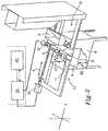
- Figure 2 illustrates a 3D printing device for manufacturing one or more 3D products in one batch by means of additive manufacturing using a layer-by-layer technique, in this case a continuous product of wood powder.
- the device includes a layer applying unit 3 for feeding out particulate material, in the shown embodiment wood powder, forming a material layer onto a support 4.
- the device according to embodiments herein may further comprise an optional reinforcing element application unit for application of reinforcing elements such as continuous reinforcing filaments e.g. nylon strings.
- the height or vertical direction corresponds to a Z axis
- the length, or longitudinal direction corresponds to an X axis
- the width, or transverse direction corresponds to a Y axis.
- the Z, X, Y axes are perpendicular to each other.
- the 3D printing device comprises a receptacle 6, which, for reasons of clarity is shown cut off at the front.
- a base plate 4 also referred to as a support 4 is arranged inside the receptacle 6 and is vertically adjustable along the Z axis.
- the support may be fixed and the other units may be adjustable in a vertical direction so as to enable the formation of material layers and the performing of a binding action.
- the layer applying unit 3 and the layer bonding unit 5 and optionally a levelling unit if such is present may be vertically adjustable with respect to the support.
- the layer applying unit 3 in the following referred to as the feeder 3, is arranged on a movable carriage 8 together with the layer bonding unit 5 and an optional layer levelling unit 7 for levelling the layer and/or for removing excessive wood powder.
- the feeder 3 and the layer levelling unit 7 are arranged for reciprocating motion along at least the X axis, i.e. in a direction parallel to the base plate 4, for example from a first end 10 to a second end 11 of the receptacle 6 and vice versa.
- the layer bonding unit 5 which exhibits at least one nozzle 12, preferably a plurality of individual nozzles 12, for deposition of binding agent, is preferably arranged for displacement along the two axes X, Y, preferably in a plane parallel to the support 4, in order to enable deposition of binding agent onto desired areas.
- a depositing means arranged for displacement along only one axis could be used. Such arrangement is less preferred as it requires a depositing means which exhibits a large number of separate nozzles arranged along an axis being perpendicular in relation to the displacement axis of the depositing means.
- Other mechanisms for depositing binding agent may alternatively be used.
- one or more robotic arms may be used such as one or more Cartesian robot arms.
- An excessive bulk material removing unit may also be provided such as a suction and/or blowing device for transporting away excessive bulk material.
- the layer levelling unit 7 may be operated to level out each applied layer, or to level out after a selected number of layers have been applied. Just as a matter of example and in general terms, the levelling unit 7 may have one levelling cycle for each cycle of the layer applying unit 3. Optionally the layer levelling unit 7 may have one cycle for every second cycle, or more, of the layer applying unit 3.
- the 3D printing device further comprises a control unit 19 operatively connected with a display unit 20.
- the display unit 20 may be remotely positioned with respect to the 3D printing device and may be connected via wires or in a wireless manner e.g. via Wifi or via other communication protocols, or via a 3G, 4G or 5G network.
- the control unit 19 may include a computer provided with a program for converting one or more virtual 3D models into signals, said signals being used for controlling different components of the device, such as the layer applying unit 3, the layer bonding unit 5, the layer levelling unit 7 and the base plate 4.
- the control unit 19 and the display unit 20 may be arranged locally at the 3D printing device or remotely thereto. A remote location is illustrated in Fig. 2 by the control unit 19 and the display unit 20 being inscribed in a dashed box.
- binding agent is applied onto selected portions of a bulk material layer in order to form a specific geometry of the 3D product by means of a controlled distribution of binding agent on each layer of bulk material.
- the portions of the layers of bulk material where binding agent has been deposited will consolidate and form the one or more 3D products, while remaining portions of the bulk material layers will remain unbonded, and thus not contribute to the finished one or more 3D products.
- the unbonded material can constitute a support for the 3D products during their manufacture.
- Figure 3 illustrates how the 3D modelling data may be manipulated by a user as represented on the display unit 20.
- Figure 3 shows a virtual image 40 of a printing batch, the virtual image 40 constituting a virtual representation of the physical printing volume PV of the batch.
- a number of 3D models representing printable 3D products are visualized in the virtual image 40; a plurality of wrenches 41, a hammer 42 and a plurality of screw drivers 43.
- the 3D models have been arranged at different positions within the printing volume PV, preferably following a Cartesian coordinate system.
- the virtual 3D printing volume PV has been partitioned into at least a first and a second virtual zone 50, 50'.
- the first and the second virtual zones 50, 50' define virtual boundaries within within the virtual 3D printing volume PV.
- each of the virtual zones 50, 50' has been assigned with a process parameter which is different from a process parameter in the other of the virtual zones 50, 50'.
- the method as disclosed herein may be carried out to produce one or more 3D product(s) having different properties in different parts of one and the same 3D product and/or having properties differing between different products.
- the process parameters may be any variable of the process which can be selected in order to control properties or characteristics of the resulting product such as material layer thickness, adhesive concentration, layer applying unit speed, layer bonding unit speed, heat, beam energy, beam size, particle size, particle type, heat on extrusion nozzle, adhesive temperature, speed of adhesive or material from nozzles, different adhesives/material, and/or colors.
- the different process parameters assigned to the different virtual zones in the virtual 3D printing volume govern the properties and characteristics of the produced 3D products, such as strength, weight, price, resolution, color, durability, environmental friendliness, food compatibility, etc.
- Figure 4 shows a view of the virtual printing volume in figure 3 as seen along the X axis.
- the virtual zones 50, 50' are defined by delimiting perimeters 51, 51'.
- all the delimiting perimeters 51, 51' are substantially straight lines, except for one delimiting perimeterwhich is a circular perimeter 51' of the virtual zone 50c which is drawn around one of the screw drivers 43.
- the periphery of the virtual 3D printing volume PV defines the outer boundaries of the adjacent virtual zones.
- at least one of the delimiting perimeters 51 is parallel with the Y axis. Hence the virtual 3D printing volume PV may thus be partitioned along at least one of the axes X, Y, Z.
- the virtual 3D printing volume By partitioning the virtual 3D printing volume into two or more virtual zones, e.g. as shown in the embodiment of figure 4 , the virtual 3D printing volume, and thus any 3D model positioned fully or partly within a virtual zone in the virtual 3D printing volume, may be assigned with different process parameters such as different material layer thickness, different bonding agent concentration or the like.
- This enables an operator to sort and coordinate manufacturing of a plurality of 3D products in a very easy and efficient manner.
- the operator may simply add at least one 3D model to the image of the virtual 3D printing volume representing the physical 3D printing volume and thereafter partition the virtual 3D printing volume into at least a first and a second virtual zone.
- the virtual zones may be assigned with different process parameters to enable 3D printed products to be manufactured with different properties in one and the same batch.
- a user may import, or otherwise add, 3D models of products to be printed to the virtual 3D printing volume, placing the 3D models fully or partly within one or more of the zones to thereby select properties for each 3D product based on the process parameters assigned to the different virtual zones in the virtual 3D printing volume. It is also possible that the 3D models are imported, or otherwise added, before the 3D printing volume has been partitioned into different zones.
- the simple process of partitioning the 3D printing volume enables an operator to assign different process parameters to different 3D products in one batch without actually manipulating the 3D models. Hence the data of the 3D models remain intact.
- the method may comprise the step of; providing a 3D model containing zone partitioning data.
- the zone partitioning, or the conditions for a zone is carried with the data for the 3D model and as such, may be imported together with data for the 3D model.
- a 3D model may thus contain data to automatically position, or assign, the 3D model to a specific zone.
- the method enables copies to be manufactured of the same 3D product but with different properties as a consequence of being formed under the influence of different process parameters. High resolution and low resolution 3D products may thus be manufactured simultaneously, and even in the same X-Y plane.
- the method as disclosed herein may involve controlling layer thickness and thereby resolution in accordance with the teaching of the co-pending international patent application PCT/EP2017/050079 .
- the method may comprise a step of; setting a first thickness of a reference layer and forming one or more material layers having a second thickness.
- the second thickness may be set as a multiple of an integer and the first thickness of the reference layer. If the first thickness of the reference layer is T r and the integer is n, then the multiple of the first thickness of the reference layer and the integer is n•T r .
- the step provides a flexible method which permits individual control of the resolution for each 3D product in a simple and effective manner even in the same plane.
- the integer may be from 1, 2, 3, 4, 5, 6, 7, 8, 9, 10 or more, such as 1-10, more preferably within the range of 1-10 000, 1-5000, or 1-1000, or 1-100. In an embodiment, the integer is >1.
- the integer 1 may thus be excluded, or in other words, in an embodiment the integer may be 2, 3, 4, 5, 6, 7, 8, 9, 10 or more, preferably within the range of 2-10, 2-10 000, 2-5000, 2-1000, 2-100.
- Figure 5 shows a schematic process diagram illustrating an embodiment of the method according to the present disclosure.
- the device uses wood powder as bulk material and a hot melt adhesive as binding agent.
- the wood powder has an average particle size of 0.05 mm.
- a computer comprising a display unit, forming a part of a control unit for manufacturing one or more 3D products by means of additive manufacturing using a layer-by-layer technique, is loaded with 3D modelling data for one or more 3D products, preferably a plurality of 3D products.
- the 3D models are a hammer, a screw driver and a wrench.
- the 3D models may be downloaded from the Internet, e.g. via a cloud based server 101 or may be retrieved from a local storage device such as a hard drive on the computer.
- the 3D models may be positioned in the virtual 3D printing volume so as to determine when and in which order they should be manufactured. The easiest way to do this is to separate the three 3D products with respect to the Z axis (as shown in figure 4 for example) so that they are not arranged in the same plane defined by the Y-X axes.
- the virtual 3D printing volume is partitioned into different virtual zones.
- the partitioning of the virtual 3D printing volume can be made in different manners such as visually by introducing delimiting perimeters e.g. in the form of lines, on an image representing the physical 3D printing volume.
- the lines represent values in a Cartesian coordinate system defined by the Z, X, and Y axes. Another way to set up delimiting perimeters may be strictly numerically.
- the operator assigns process parameters to each virtual zone.
- the operator may assign deviations from a number of pre-set process parameters which automatically are assigned to each zone.
- a process parameter for a first zone may be that the thickness of an applied material layer is set to 0.1 mm
- a process parameter for a second zone may be that the thickness of an applied material layer is set to 0.3 mm.
- the difference in thickness of the applied material layers will provide two 3D products produced from 3D models positioned in the different zones with different resolution.
- the different process parameters assigned to the different virtual zones of the partitioned virtual printing volume may e.g. be used to produce 3D products differing in terms of having a different material/bonding agent ratio, or as an option having different material layer thickness but having the same material/bonding agent ratio.
- the 3D models and the partitioned 3D printing volume will be converted to 3D printing device readable data and be forwarded to the 3D printing device as instructions to the different units of the 3D printing device.
- the data formed by the above input and terms to the 3D models may optionally be sent to the device control unit which converts the input data to readable data containing instructions for the 3D printing device.
- the 3D printing device is now ready for manufacturing the selected 3D products.
- the layer applying unit repeatedly applies material layers having a selectable thickness, such as 0.1 mm, across the available printing volume, i.e. the plane defined by the Y-X axes, while the layer bonding unit repeatedly applies binding agent in a pattern corresponding to a specific slice of the one or more 3D model(s) or binds the layer in any other suitable way.
- the application of binding agent is controlled so that the correct amount of cycles of material layers are achieved for the specific 3D model.
- the layer bonding unit after each cycle the layer applying unit has applied a material layer having the thickness of 0.1 mm, the layer bonding unit applies binding agent every cycle in the 1 st zone and on the selected area of the wrench in the 1 st zone 50a.
- the layer bonding unit applies binding agent every 3 rd cycle on the selected area of the screw driver in the 2 nd zone 50b.
- the layer bonding unit applies binding agent every cycle on the selected area of the screw driver in the 3 rd zone 50c.
- the layer bonding unit applies binding agent every cycle on the selected area of the wrench. This may be controlled by selectively opening and closing the valves jetting the binding agent from the layer bonding unit for example. Thereby the different resolutions are achieved.
- the layers may be formed by using a lowest common denominator, i.e. a reference layer, when selecting the thickness of the material layers in the batch. Each material layer is then formed as a multiple of the reference layer and an integer.
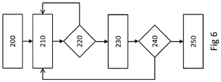
- a method may comprise one or more of the following steps: At step 200 the control unit of the 3D printing device receives the readable input data derived from the one or more 3D model(s) and the different virtual zones and their delimiting perimeters of the 3D printing volume.
- the layer applying unit applies one or more bulk material layers, e.g. of particulate material, preferably wood powder, such that a material layer having the minimum thickness set by the operator, in this case 0.1 mm is formed.
- the material layer thickness of 0.1 mm is selected in this case with reference to figure 4 and the 1 st zone.
- An optional levelling step may be performed using a levelling unit after each applied material layer, or after a selected number of applied material layers.
- the control unit checks if the readable input data demands that binding agent is to be deposited onto selected surfaces of the previously laid material layer based on the thickness for each material layer and the relative positions of the 3D models in the 3D printing volume with respect to the X, Y, and Z axes. It should be noted that other process parameters may have been selected. Hence the step may be to check the demands for the selected process parameter e.g. adhesive concentration, layer applying unit speed, layer bonding unit speed, strength, weight, price, resolution environmental aspects just to mention a few.
- the selected process parameter e.g. adhesive concentration, layer applying unit speed, layer bonding unit speed, strength, weight, price, resolution environmental aspects just to mention a few.
- binding agent is applied on the selected surfaces.
- the layer applying unit applies another material layer.
- control unit checks to see if additional material layers are required. If yes, return to 210.
- step 250 the procedure is terminated and optional post-treatment and actions may be performed such as removing access material, emptying the printing volume, performing cleaning and service procedures etc.
- Bulk material is herein meant any material which may be used to form a 3D product by performing a binding action on the bulk material.
- the bulk material is a particulate material but liquid materials may be used such as liquid polymers, wax, metal, alloys or the like.
- the particulate material may be an inert particulate material or a reactant particulate material.
- a material layer may comprise one or more layers of bulk material.
- inert particulate material may be selected from metals, inert polymers, inert salts, inert organic materials or inert ceramics, or combinations thereof.
- metals examples include aluminium, steel, titanium, iron, alloys, or the like.
- inert polymers include poly (methyl methacrylate), polystyrene, polyamide, polyester, a latex, polyethylene, polypropylene, polyurethane, polyvinyl chloride, polyvinyl acetate, cross-linked polyvinyl pyrrolidone, hydrophilic polyurethane, poly (ethylene terephthalate), thermoplastic urethane, styrene-acrylonitrile copolymer, thermoplastic polyolefin, an epoxy-based polymer, polyether, polyamine, a polyacid, a polycarbonate, a vinyl polymer, an aromatic polyamide, a diene polymer, poly (phenylene oxide), polysiloxane, polynorbornene, polyisoprene, a polyphenylene ether, styrene-butadiene block copolymer, acrylonitrile-butadiene-styrene, high impact polystyrene and copolymers thereof.
- inert salts include sodium carbonate, sodium bicarbonate, sodium borate, sodium chloride, sodium sulfate, potassium sulfate, potassium chloride, magnesium sulfate, magnesium chloride, potassium aluminum sulfate, sodium polyphosphate, sodium acetate, hydrous calcium sulphate, calcium phosphate, sodium silicate, and hydrated lime (Ca (OH) 2).
- inert organic materials include starch, cellulose fibers, wood powder, wax, resin, bone, protein, carbohydrates, sugars, textile fibers and dietary fibers.
- inert ceramics include gypsum, limestone, clay, aluminum oxide, aluminum silicate, calcium silicate, silicon dioxide, titanium dioxide, glass, iron oxide, zinc oxide, magnetite, aluminum hydroxide, magnesium oxide, calcium phosphate, zirconium silicate, silicon carbide, boron nitride, boron carbide and borosilicate.
- a preferred bulk material may be wood powder.
- the expression wood powder as used herein refers to a powder made of a wood material. Different tree species, soft wood or hard wood, such as pine, spruce, birch, larch or others, and different forms of wood originating from branches, trunks, stumps, roots of trees, or in the form of wood waste, such as recycled wood waste, can be used as a starting material for producing the wood powder. Examples of suitable wood materials are wood chips originating from machining of homogenous wood, such as sawdust, cutter shavings, or the like. Wood powder will thus include the same substances as the initial wood does such as lignin, pectin and ash.
- cellulose or cellulose fibers may be derived from wood material but have been treated in a number of process steps, and thus represents another kind of material.
- a cellulose fiber is thus a more refined and elegant material and in some aspects lack substances that wood powder would include.
- cellulose fibers may be natural occurring fibers such as cotton fibers or linen fibers, manufactured fibers from e.g. plants which have been processed into pulp. Examples of plants are crops, wood, leaves or the like. Rayon or viscose fibers are examples of manufactured cellulose fibers.
- wood powder as a bulk material may be advantageous since wood powder can be produced at a low cost, from an easily accessible raw material (wood). The usage of wood powder may even imply that material considered as waste material becomes useful. Furthermore, wood powder is biodegradable and can be used to manufacture biodegradable and thereby environmentally friendly 3D products.
- the particles of the particulate material such as powder e.g. wood powder
- the particle size can be from relatively small, so that the powder obtains a flour-like consistency, to relatively large, implying that the individual particles can be distinguished at a visual inspection.
- the particles of a given powder are substantially of the same size in order to obtain a uniform quality of the final product.
- a particle size in the size interval 0.001-5 mm, and preferably of the order of 0.01-2 mm, can be used when forming the material layers. If, for example, a particle size of 1 mm is chosen, it can be ensured by means of filtration, sometimes referred to as sieve analysis, that the particles in one and the same powder has a size which does not exceed, for example, 1.2 mm, and a size which does not fall below, for example, 0.8 mm.
- the size of the individual particulate matter may be as small as atom size, or nano size.
- atom by atom material layers may be formed using molecular beam epitaxy (MBE) which allows for the vertical stacking of individual atomic layers i.e. the Z-axis, in combination with scanning probe lithography, which uses an extremely sharp tip to move and place individual atoms in a lateral direction, i.e. the X- and Y-axes.
- a Laser particle sizer Analysette 22 NanoTec, by Fritsch may be used. Such device generally has measuring range of 0.01 - 2100 ⁇ m. Standard ISO 13320. Following theory Fraunhofer, Mie. Fraunhofer theory for larger particles when their exact optical parameters are unknown and Mie theory for the smallest particles with known optical parameters. It is possible to select both theories in a FRITSCH MaS control software.
- particle size measurements methods which may be used to determine a particle size are sieve analysis, sedimentation, image particle analysis, microscope counting to mention a few.
- Suitable binding actions may be to add binding agent, to add one or more chemical reactants to form a binding agent on or in the material layer, heat treatment to e.g. melt portions of the material layer such that the material layer is bonded.
- Other binding actions may be radiation treatment, electromagnetic radiation, electron beam, light treatment or combinations thereof.
- binding agents may be used.
- the useful binding agents have in common that they are capable of bonding together the powder, or particles, in the bulk material so that a desired strength or other desired properties of the 3D product can be achieved.
- the binding agent can be water-based, but the binding agent is suitably water resistant. Whether the binding agent should be water resistant or not, however, depends on the 3D product which is to be manufactured and possible post-treatments of the product.
- One suitable binding agent is wood glue, but also a hot melt adhesive, for example a plastic-based one, which is heated during application could be used. Most wood glues which are present on the market have the advantages of being relatively cost efficient and easy to handle, environmentally friendly and particularly suited for bonding wood materials.
- Non-limiting examples of glue are Polyvinyl acetate (PVA) glue, animal glue such as hide glue, Polyurethane glue, Urea-formaldehyde resin adhesives, Resorcinol-formaldehyde resin glue, Cyanoacrylate glue preferably with additive for delayed hardening time.
- PVA Polyvinyl acetate
- animal glue such as hide glue
- Polyurethane glue Urea-formaldehyde resin adhesives
- Resorcinol-formaldehyde resin glue Resorcinol-formaldehyde resin glue
- Cyanoacrylate glue preferably with additive for delayed hardening time.
- the binding agent can also be applied as two or more individual components which together form a binding agent, e.g. via a chemical reaction between the two or more components such as epoxy resin and hardener.
- the binding agent may be formed on the material layer itself or before being applied onto the material layer.
- the concentration or dilution of the binding agent (water content if a water-based binding agent is concerned) can be varied.
- the moisture content of the used bulk material has a certain importance, since the total amount of moisture originating from the powder and the binding agent has to be capable of at least wetting the material to the desired extent in order to enable bonding of selected portions of the bulk material layers.
- the moisture content of the bulk material should also be adapted in order to give the bulk material properties making the bulk material easy to work when being laid out in layers.
- the binding agent may be applied such that each layer is saturated with binding agent, or such that the binding agent sinks into the preceding material layer, or even into preceding material layers. In the latter case, binding agent is applied such that the material layer is bonded together but not saturated.
- binding agent may be applied onto a subsequently applied material layer but yet still penetrate into the preceding one or more material layers. Binding agent may penetrate into two or more such as 2-6 previous material layers. This will provide a 3D product which is continuous in terms of that no, or substantially no, material layers may be identified should the 3D product be cut open and inspected.
- the particulate material constituting the base of the material such as wood powder and, accordingly, the base of the finished 3D product, it is also possible to add small quantities of other substances/materials to the binding agent and/or to the material layer in order to obtain specific properties of the 3D product formed from the particulate material.
- the particulate material such as wood powder, should form at least 50 %, 51 % or more, 60 % or more, 70 % or more, 80 % or more, 90 % or more, 95 % or more of the material layer.
- different substances can be added to the binding agent and/or the material layer, e.g. as a mixture with the particulate material.
- Such an additive is colouring agent, colouring pigment, or the like, in order to give the end product a certain colour.
- colouring agent colouring pigment, or the like
- the finished product can obtain different colours on different visible surfaces.
- reinforcing elements such as reinforcing strings, e.g. nylon strings.
- Flame retardants are generally divided into three groups; minerals, Organohalogen compounds and Organophosphorus compounds. Examples of minerals are; magnesium hydroxide (MDH), aluminium hydroxide (ATH), red phosphorus, boron compounds, huntite and hydromagnesite, and various hydrates.
- MDH magnesium hydroxide
- ATH aluminium hydroxide
- red phosphorus red phosphorus
- boron compounds huntite and hydromagnesite, and various hydrates.
- organohalogen compounds are organochlorines such as chlorendic acid derivatives and chlorinated paraffins; polymeric brominated compounds such as brominated polystyrenes, brominated carbonate oligomers (BCOs), brominated epoxy oligomers (BEOs), tetrabromophthalic anyhydride, tetrabromobisphenol A (TBBPA) and hexabromocyclododecane (HBCD), organobromines such as decabromodiphenyl ether (decaBDE), decabromodiphenyl ethane (a replacement for decaBDE).
- organochlorines such as chlorendic acid derivatives and chlorinated paraffins
- polymeric brominated compounds such as brominated polystyrenes, brominated carbonate oligomers (BCOs), brominated epoxy oligomers (BEOs), tetrabromophthalic anyhydride, tetrabromobisphenol A (
- a flame retardant synergist may further be added to improve the efficiency of the flame retardant, such as antimony trioxide, pentoxide and sodium antimonate.
- organophosphorus compounds are phosphonates such as dimethyl methylphosphonate (DMMP); and phosphinates such as aluminium diethyl phosphinate, triphenyl phosphate (TPP), resorcinol bis(diphenylphosphate) (RDP), bisphenol A diphenyl phosphate (BADP), and tricresyl phosphate (TCP).
- DMMP dimethyl methylphosphonate
- phosphinates such as aluminium diethyl phosphinate, triphenyl phosphate (TPP), resorcinol bis(diphenylphosphate) (RDP), bisphenol A diphenyl phosphate (BADP), and tricresyl phosphate (TCP).
- Flame retardants comprising phosphorus and a halogen may also be used such as and chlorinated organophosphates such as tris(1,3-dichloro-2-propyl)phosphate (chlorinated tris or TDCPP) and tetrakis(2-chlorethyl)dichloroisopentyldiphosphate (V6), tris(2,3-dibromopropyl) phosphate (brominated tris).
- chlorinated organophosphates such as tris(1,3-dichloro-2-propyl)phosphate (chlorinated tris or TDCPP) and tetrakis(2-chlorethyl)dichloroisopentyldiphosphate (V6), tris(2,3-dibromopropyl) phosphate (brominated tris).
Landscapes
- Chemical & Material Sciences (AREA)
- Engineering & Computer Science (AREA)
- Materials Engineering (AREA)
- Manufacturing & Machinery (AREA)
- Physics & Mathematics (AREA)
- Mechanical Engineering (AREA)
- Optics & Photonics (AREA)
Priority Applications (1)
| Application Number | Priority Date | Filing Date | Title |
|---|---|---|---|
| PL17818164T PL3565714T3 (pl) | 2017-01-03 | 2017-12-21 | Sposób drukowania produktu w 3d oraz urządzenie drukujące 3d |
Applications Claiming Priority (2)
| Application Number | Priority Date | Filing Date | Title |
|---|---|---|---|
| PCT/EP2017/050077 WO2018127274A1 (en) | 2017-01-03 | 2017-01-03 | A method for printing a 3d product and a 3d printing device |
| PCT/EP2017/084124 WO2018127429A1 (en) | 2017-01-03 | 2017-12-21 | A method for printing a 3d product and a 3d printing device |
Publications (2)
| Publication Number | Publication Date |
|---|---|
| EP3565714A1 EP3565714A1 (en) | 2019-11-13 |
| EP3565714B1 true EP3565714B1 (en) | 2020-10-21 |
Family
ID=57821949
Family Applications (1)
| Application Number | Title | Priority Date | Filing Date |
|---|---|---|---|
| EP17818164.0A Active EP3565714B1 (en) | 2017-01-03 | 2017-12-21 | A method for printing a 3d product and a 3d printing device |
Country Status (4)
| Country | Link |
|---|---|
| EP (1) | EP3565714B1 (pl) |
| ES (1) | ES2843106T3 (pl) |
| PL (1) | PL3565714T3 (pl) |
| WO (2) | WO2018127274A1 (pl) |
Families Citing this family (5)
| Publication number | Priority date | Publication date | Assignee | Title |
|---|---|---|---|---|
| US11348313B2 (en) | 2019-03-27 | 2022-05-31 | Hewlett-Packard Development Company, L.P. | Arranging three-dimensional models |
| US11813805B2 (en) | 2019-05-29 | 2023-11-14 | General Electric Company | Tool for optimal part consolidation selection for additive manufacturing |
| WO2021150248A1 (en) * | 2020-01-24 | 2021-07-29 | Hewlett-Packard Development Company, L.P. | Energy source setting |
| CN113649591A (zh) * | 2021-06-28 | 2021-11-16 | 华中科技大学鄂州工业技术研究院 | 一种金属/陶瓷粉末烧结分区的3d打印方法 |
| CN115157671B (zh) * | 2022-08-31 | 2023-06-13 | 湖北地创三维科技有限公司 | 一种3d打印机x轴调平机构及调平方法 |
Family Cites Families (6)
| Publication number | Priority date | Publication date | Assignee | Title |
|---|---|---|---|---|
| DE10235434A1 (de) * | 2002-08-02 | 2004-02-12 | Eos Gmbh Electro Optical Systems | Vorrichtung und Verfahren zum Herstellen eins dreidimensionalen Objekts mittels eines generativen Fertigungsverfahrens |
| SE527645C2 (sv) | 2004-09-20 | 2006-05-02 | Jerry Edvinsson | Förfarande och anordning för tillverkning av träpulverbaserade produkter |
| JP2011156783A (ja) * | 2010-02-02 | 2011-08-18 | Sony Corp | 3次元造形装置、3次元造形物の製造方法及び3次元造形物 |
| KR20150091945A (ko) * | 2014-02-04 | 2015-08-12 | 삼성메디슨 주식회사 | 의료 영상 처리 장치, 방법, 및 컴퓨터 판독가능 기록매체 |
| EP3200981B1 (en) * | 2014-09-30 | 2023-01-25 | Hewlett-Packard Development Company, L.P. | Virtual build beds |
| WO2017108108A1 (en) * | 2015-12-22 | 2017-06-29 | Hewlett-Packard Development Company, L.P. | Print data generation systems |
-
2017
- 2017-01-03 WO PCT/EP2017/050077 patent/WO2018127274A1/en active Application Filing
- 2017-12-21 WO PCT/EP2017/084124 patent/WO2018127429A1/en active Search and Examination
- 2017-12-21 PL PL17818164T patent/PL3565714T3/pl unknown
- 2017-12-21 ES ES17818164T patent/ES2843106T3/es active Active
- 2017-12-21 EP EP17818164.0A patent/EP3565714B1/en active Active
Non-Patent Citations (1)
| Title |
|---|
| None * |
Also Published As
| Publication number | Publication date |
|---|---|
| ES2843106T3 (es) | 2021-07-15 |
| WO2018127429A1 (en) | 2018-07-12 |
| PL3565714T3 (pl) | 2021-05-17 |
| EP3565714A1 (en) | 2019-11-13 |
| WO2018127274A1 (en) | 2018-07-12 |
Similar Documents
| Publication | Publication Date | Title |
|---|---|---|
| EP3565714B1 (en) | A method for printing a 3d product and a 3d printing device | |
| EP3565713B1 (en) | A method for printing a 3d product and a 3d printing device | |
| JP6868657B2 (ja) | 繊維強化加法的製造の方法 | |
| US20190329487A1 (en) | System, method and apparatus for 3d printing | |
| Gebhardt et al. | Additive manufacturing: 3D printing for prototyping and manufacturing | |
| US10261499B2 (en) | Device and method of manufacturing customizable three-dimensional objects | |
| US9573323B2 (en) | Method for generating and building support structures with deposition-based digital manufacturing systems | |
| EP1791683B1 (en) | Method for manufacturing products based on wood powder | |
| CN108139734A (zh) | 打印数据生成系统 | |
| Ribeiro | 3D printing with metals | |
| TWI581946B (zh) | Method and apparatus for printing three - dimensional building blocks by rapid prototyping technology | |
| EP3565707B1 (en) | A method for printing a 3d product and a 3d printing device | |
| CN107211072A (zh) | 用于三维对象的结构形成 | |
| EP2855117B1 (en) | Method and device for layer-by-layer forming an object | |
| Heynick et al. | 3D CAD, CAM and rapid prototyping | |
| EP3551429B1 (en) | Color representation of a property of a 3d object | |
| CN103802319A (zh) | 一种增材制造方法 | |
| Mai et al. | Fabricating wood-like textures on multicurved 3D printed architectural elements | |
| Ermolai et al. | Influence of nozzle parameters in 3D printing under the manufacturing time | |
| Huang | Development of a software procedure for curved layered fused deposition modelling (CLFDM) | |
| Bandyopadhyay et al. | Polymer Processing: Design, Printing and Applications of Multi-Dimensional Techniques | |
| Brody | 3D Printing: Rapid Prototyping From Food to Food Packaging | |
| ALMAHEEN et al. | DEVELOPING A NOVEL TECHNIQUE FOR THE FABRICATION OF PLA-CERAMICS COMPOSITE FILAMENTS USING FDM 3D PRINTING PROCESS |
Legal Events
| Date | Code | Title | Description |
|---|---|---|---|
| STAA | Information on the status of an ep patent application or granted ep patent |
Free format text: STATUS: UNKNOWN |
|
| STAA | Information on the status of an ep patent application or granted ep patent |
Free format text: STATUS: THE INTERNATIONAL PUBLICATION HAS BEEN MADE |
|
| PUAI | Public reference made under article 153(3) epc to a published international application that has entered the european phase |
Free format text: ORIGINAL CODE: 0009012 |
|
| STAA | Information on the status of an ep patent application or granted ep patent |
Free format text: STATUS: REQUEST FOR EXAMINATION WAS MADE |
|
| 17P | Request for examination filed |
Effective date: 20190604 |
|
| AK | Designated contracting states |
Kind code of ref document: A1 Designated state(s): AL AT BE BG CH CY CZ DE DK EE ES FI FR GB GR HR HU IE IS IT LI LT LU LV MC MK MT NL NO PL PT RO RS SE SI SK SM TR |
|
| AX | Request for extension of the european patent |
Extension state: BA ME |
|
| DAV | Request for validation of the european patent (deleted) | ||
| DAX | Request for extension of the european patent (deleted) | ||
| RIC1 | Information provided on ipc code assigned before grant |
Ipc: B29C 64/165 20170101ALI20200327BHEP Ipc: B33Y 50/02 20150101ALI20200327BHEP Ipc: B29C 67/00 20170101AFI20200327BHEP Ipc: B29C 64/182 20170101ALI20200327BHEP Ipc: B29C 64/393 20170101ALI20200327BHEP Ipc: B33Y 10/00 20150101ALI20200327BHEP |
|
| GRAP | Despatch of communication of intention to grant a patent |
Free format text: ORIGINAL CODE: EPIDOSNIGR1 |
|
| STAA | Information on the status of an ep patent application or granted ep patent |
Free format text: STATUS: GRANT OF PATENT IS INTENDED |
|
| INTG | Intention to grant announced |
Effective date: 20200512 |
|
| GRAS | Grant fee paid |
Free format text: ORIGINAL CODE: EPIDOSNIGR3 |
|
| GRAA | (expected) grant |
Free format text: ORIGINAL CODE: 0009210 |
|
| STAA | Information on the status of an ep patent application or granted ep patent |
Free format text: STATUS: THE PATENT HAS BEEN GRANTED |
|
| AK | Designated contracting states |
Kind code of ref document: B1 Designated state(s): AL AT BE BG CH CY CZ DE DK EE ES FI FR GB GR HR HU IE IS IT LI LT LU LV MC MK MT NL NO PL PT RO RS SE SI SK SM TR |
|
| REG | Reference to a national code |
Ref country code: GB Ref legal event code: FG4D |
|
| REG | Reference to a national code |
Ref country code: CH Ref legal event code: EP |
|
| REG | Reference to a national code |
Ref country code: IE Ref legal event code: FG4D |
|
| REG | Reference to a national code |
Ref country code: DE Ref legal event code: R096 Ref document number: 602017026060 Country of ref document: DE |
|
| REG | Reference to a national code |
Ref country code: AT Ref legal event code: REF Ref document number: 1325410 Country of ref document: AT Kind code of ref document: T Effective date: 20201115 |
|
| REG | Reference to a national code |
Ref country code: NL Ref legal event code: FP |
|
| REG | Reference to a national code |
Ref country code: SE Ref legal event code: TRGR |
|
| REG | Reference to a national code |
Ref country code: AT Ref legal event code: MK05 Ref document number: 1325410 Country of ref document: AT Kind code of ref document: T Effective date: 20201021 |
|
| PG25 | Lapsed in a contracting state [announced via postgrant information from national office to epo] |
Ref country code: GR Free format text: LAPSE BECAUSE OF FAILURE TO SUBMIT A TRANSLATION OF THE DESCRIPTION OR TO PAY THE FEE WITHIN THE PRESCRIBED TIME-LIMIT Effective date: 20210122 Ref country code: NO Free format text: LAPSE BECAUSE OF FAILURE TO SUBMIT A TRANSLATION OF THE DESCRIPTION OR TO PAY THE FEE WITHIN THE PRESCRIBED TIME-LIMIT Effective date: 20210121 Ref country code: RS Free format text: LAPSE BECAUSE OF FAILURE TO SUBMIT A TRANSLATION OF THE DESCRIPTION OR TO PAY THE FEE WITHIN THE PRESCRIBED TIME-LIMIT Effective date: 20201021 Ref country code: PT Free format text: LAPSE BECAUSE OF FAILURE TO SUBMIT A TRANSLATION OF THE DESCRIPTION OR TO PAY THE FEE WITHIN THE PRESCRIBED TIME-LIMIT Effective date: 20210222 Ref country code: FI Free format text: LAPSE BECAUSE OF FAILURE TO SUBMIT A TRANSLATION OF THE DESCRIPTION OR TO PAY THE FEE WITHIN THE PRESCRIBED TIME-LIMIT Effective date: 20201021 |
|
| REG | Reference to a national code |
Ref country code: LT Ref legal event code: MG4D |
|
| PG25 | Lapsed in a contracting state [announced via postgrant information from national office to epo] |
Ref country code: BG Free format text: LAPSE BECAUSE OF FAILURE TO SUBMIT A TRANSLATION OF THE DESCRIPTION OR TO PAY THE FEE WITHIN THE PRESCRIBED TIME-LIMIT Effective date: 20210121 Ref country code: LV Free format text: LAPSE BECAUSE OF FAILURE TO SUBMIT A TRANSLATION OF THE DESCRIPTION OR TO PAY THE FEE WITHIN THE PRESCRIBED TIME-LIMIT Effective date: 20201021 Ref country code: IS Free format text: LAPSE BECAUSE OF FAILURE TO SUBMIT A TRANSLATION OF THE DESCRIPTION OR TO PAY THE FEE WITHIN THE PRESCRIBED TIME-LIMIT Effective date: 20210221 Ref country code: AT Free format text: LAPSE BECAUSE OF FAILURE TO SUBMIT A TRANSLATION OF THE DESCRIPTION OR TO PAY THE FEE WITHIN THE PRESCRIBED TIME-LIMIT Effective date: 20201021 |
|
| PG25 | Lapsed in a contracting state [announced via postgrant information from national office to epo] |
Ref country code: HR Free format text: LAPSE BECAUSE OF FAILURE TO SUBMIT A TRANSLATION OF THE DESCRIPTION OR TO PAY THE FEE WITHIN THE PRESCRIBED TIME-LIMIT Effective date: 20201021 |
|
| REG | Reference to a national code |
Ref country code: ES Ref legal event code: FG2A Ref document number: 2843106 Country of ref document: ES Kind code of ref document: T3 Effective date: 20210715 |
|
| REG | Reference to a national code |
Ref country code: DE Ref legal event code: R097 Ref document number: 602017026060 Country of ref document: DE |
|
| PG25 | Lapsed in a contracting state [announced via postgrant information from national office to epo] |
Ref country code: SM Free format text: LAPSE BECAUSE OF FAILURE TO SUBMIT A TRANSLATION OF THE DESCRIPTION OR TO PAY THE FEE WITHIN THE PRESCRIBED TIME-LIMIT Effective date: 20201021 Ref country code: SK Free format text: LAPSE BECAUSE OF FAILURE TO SUBMIT A TRANSLATION OF THE DESCRIPTION OR TO PAY THE FEE WITHIN THE PRESCRIBED TIME-LIMIT Effective date: 20201021 Ref country code: RO Free format text: LAPSE BECAUSE OF FAILURE TO SUBMIT A TRANSLATION OF THE DESCRIPTION OR TO PAY THE FEE WITHIN THE PRESCRIBED TIME-LIMIT Effective date: 20201021 Ref country code: LT Free format text: LAPSE BECAUSE OF FAILURE TO SUBMIT A TRANSLATION OF THE DESCRIPTION OR TO PAY THE FEE WITHIN THE PRESCRIBED TIME-LIMIT Effective date: 20201021 Ref country code: EE Free format text: LAPSE BECAUSE OF FAILURE TO SUBMIT A TRANSLATION OF THE DESCRIPTION OR TO PAY THE FEE WITHIN THE PRESCRIBED TIME-LIMIT Effective date: 20201021 |
|
| REG | Reference to a national code |
Ref country code: CH Ref legal event code: PL |
|
| PLBE | No opposition filed within time limit |
Free format text: ORIGINAL CODE: 0009261 |
|
| STAA | Information on the status of an ep patent application or granted ep patent |
Free format text: STATUS: NO OPPOSITION FILED WITHIN TIME LIMIT |
|
| PG25 | Lapsed in a contracting state [announced via postgrant information from national office to epo] |
Ref country code: DK Free format text: LAPSE BECAUSE OF FAILURE TO SUBMIT A TRANSLATION OF THE DESCRIPTION OR TO PAY THE FEE WITHIN THE PRESCRIBED TIME-LIMIT Effective date: 20201021 Ref country code: MC Free format text: LAPSE BECAUSE OF FAILURE TO SUBMIT A TRANSLATION OF THE DESCRIPTION OR TO PAY THE FEE WITHIN THE PRESCRIBED TIME-LIMIT Effective date: 20201021 |
|
| REG | Reference to a national code |
Ref country code: BE Ref legal event code: MM Effective date: 20201231 |
|
| 26N | No opposition filed |
Effective date: 20210722 |
|
| PG25 | Lapsed in a contracting state [announced via postgrant information from national office to epo] |
Ref country code: LU Free format text: LAPSE BECAUSE OF NON-PAYMENT OF DUE FEES Effective date: 20201221 Ref country code: AL Free format text: LAPSE BECAUSE OF FAILURE TO SUBMIT A TRANSLATION OF THE DESCRIPTION OR TO PAY THE FEE WITHIN THE PRESCRIBED TIME-LIMIT Effective date: 20201021 Ref country code: IE Free format text: LAPSE BECAUSE OF NON-PAYMENT OF DUE FEES Effective date: 20201221 |
|
| PG25 | Lapsed in a contracting state [announced via postgrant information from national office to epo] |
Ref country code: SI Free format text: LAPSE BECAUSE OF FAILURE TO SUBMIT A TRANSLATION OF THE DESCRIPTION OR TO PAY THE FEE WITHIN THE PRESCRIBED TIME-LIMIT Effective date: 20201021 Ref country code: CH Free format text: LAPSE BECAUSE OF NON-PAYMENT OF DUE FEES Effective date: 20201231 Ref country code: LI Free format text: LAPSE BECAUSE OF NON-PAYMENT OF DUE FEES Effective date: 20201231 |
|
| PG25 | Lapsed in a contracting state [announced via postgrant information from national office to epo] |
Ref country code: IS Free format text: LAPSE BECAUSE OF FAILURE TO SUBMIT A TRANSLATION OF THE DESCRIPTION OR TO PAY THE FEE WITHIN THE PRESCRIBED TIME-LIMIT Effective date: 20210221 Ref country code: MT Free format text: LAPSE BECAUSE OF FAILURE TO SUBMIT A TRANSLATION OF THE DESCRIPTION OR TO PAY THE FEE WITHIN THE PRESCRIBED TIME-LIMIT Effective date: 20201021 Ref country code: CY Free format text: LAPSE BECAUSE OF FAILURE TO SUBMIT A TRANSLATION OF THE DESCRIPTION OR TO PAY THE FEE WITHIN THE PRESCRIBED TIME-LIMIT Effective date: 20201021 |
|
| PG25 | Lapsed in a contracting state [announced via postgrant information from national office to epo] |
Ref country code: MK Free format text: LAPSE BECAUSE OF FAILURE TO SUBMIT A TRANSLATION OF THE DESCRIPTION OR TO PAY THE FEE WITHIN THE PRESCRIBED TIME-LIMIT Effective date: 20201021 |
|
| PG25 | Lapsed in a contracting state [announced via postgrant information from national office to epo] |
Ref country code: BE Free format text: LAPSE BECAUSE OF NON-PAYMENT OF DUE FEES Effective date: 20201231 |
|
| PGFP | Annual fee paid to national office [announced via postgrant information from national office to epo] |
Ref country code: GB Payment date: 20231213 Year of fee payment: 7 |
|
| PGFP | Annual fee paid to national office [announced via postgrant information from national office to epo] |
Ref country code: TR Payment date: 20231110 Year of fee payment: 7 Ref country code: SE Payment date: 20231220 Year of fee payment: 7 Ref country code: NL Payment date: 20231212 Year of fee payment: 7 Ref country code: IT Payment date: 20231211 Year of fee payment: 7 Ref country code: FR Payment date: 20231222 Year of fee payment: 7 Ref country code: CZ Payment date: 20231123 Year of fee payment: 7 |
|
| PGFP | Annual fee paid to national office [announced via postgrant information from national office to epo] |
Ref country code: PL Payment date: 20231113 Year of fee payment: 7 |
|
| PGFP | Annual fee paid to national office [announced via postgrant information from national office to epo] |
Ref country code: ES Payment date: 20240320 Year of fee payment: 7 |
|
| PGFP | Annual fee paid to national office [announced via postgrant information from national office to epo] |
Ref country code: DE Payment date: 20240112 Year of fee payment: 7 |