EP3565052A1 - Système et procédé d'inspection de l'état d'alignement d'une plaque d'électrode - Google Patents
Système et procédé d'inspection de l'état d'alignement d'une plaque d'électrode Download PDFInfo
- Publication number
- EP3565052A1 EP3565052A1 EP19171785.9A EP19171785A EP3565052A1 EP 3565052 A1 EP3565052 A1 EP 3565052A1 EP 19171785 A EP19171785 A EP 19171785A EP 3565052 A1 EP3565052 A1 EP 3565052A1
- Authority
- EP
- European Patent Office
- Prior art keywords
- plate
- separator
- aligned state
- electrode plate
- cathode
- Prior art date
- Legal status (The legal status is an assumption and is not a legal conclusion. Google has not performed a legal analysis and makes no representation as to the accuracy of the status listed.)
- Granted
Links
- 238000007689 inspection Methods 0.000 title claims abstract description 115
- 238000000034 method Methods 0.000 title claims abstract description 67
- 238000003384 imaging method Methods 0.000 claims abstract description 23
- 230000007547 defect Effects 0.000 claims description 13
- 230000001186 cumulative effect Effects 0.000 claims description 8
- 238000004364 calculation method Methods 0.000 claims description 5
- 230000001678 irradiating effect Effects 0.000 claims description 2
- 230000002950 deficient Effects 0.000 abstract description 22
- 238000004519 manufacturing process Methods 0.000 abstract description 4
- 239000002699 waste material Substances 0.000 abstract description 2
- 239000000463 material Substances 0.000 description 4
- 230000000712 assembly Effects 0.000 description 3
- 238000000429 assembly Methods 0.000 description 3
- WHXSMMKQMYFTQS-UHFFFAOYSA-N Lithium Chemical compound [Li] WHXSMMKQMYFTQS-UHFFFAOYSA-N 0.000 description 2
- 229910052744 lithium Inorganic materials 0.000 description 2
- 230000004075 alteration Effects 0.000 description 1
- 238000005516 engineering process Methods 0.000 description 1
- 238000005259 measurement Methods 0.000 description 1
- 238000012986 modification Methods 0.000 description 1
- 230000004048 modification Effects 0.000 description 1
- 230000005855 radiation Effects 0.000 description 1
Images


Classifications
-
- G—PHYSICS
- G01—MEASURING; TESTING
- G01N—INVESTIGATING OR ANALYSING MATERIALS BY DETERMINING THEIR CHEMICAL OR PHYSICAL PROPERTIES
- G01N21/00—Investigating or analysing materials by the use of optical means, i.e. using sub-millimetre waves, infrared, visible or ultraviolet light
- G01N21/84—Systems specially adapted for particular applications
- G01N21/88—Investigating the presence of flaws or contamination
- G01N21/8803—Visual inspection
-
- H—ELECTRICITY
- H01—ELECTRIC ELEMENTS
- H01M—PROCESSES OR MEANS, e.g. BATTERIES, FOR THE DIRECT CONVERSION OF CHEMICAL ENERGY INTO ELECTRICAL ENERGY
- H01M10/00—Secondary cells; Manufacture thereof
- H01M10/42—Methods or arrangements for servicing or maintenance of secondary cells or secondary half-cells
- H01M10/4285—Testing apparatus
-
- G—PHYSICS
- G01—MEASURING; TESTING
- G01N—INVESTIGATING OR ANALYSING MATERIALS BY DETERMINING THEIR CHEMICAL OR PHYSICAL PROPERTIES
- G01N21/00—Investigating or analysing materials by the use of optical means, i.e. using sub-millimetre waves, infrared, visible or ultraviolet light
- G01N21/84—Systems specially adapted for particular applications
- G01N21/88—Investigating the presence of flaws or contamination
- G01N21/95—Investigating the presence of flaws or contamination characterised by the material or shape of the object to be examined
-
- H—ELECTRICITY
- H01—ELECTRIC ELEMENTS
- H01M—PROCESSES OR MEANS, e.g. BATTERIES, FOR THE DIRECT CONVERSION OF CHEMICAL ENERGY INTO ELECTRICAL ENERGY
- H01M10/00—Secondary cells; Manufacture thereof
- H01M10/05—Accumulators with non-aqueous electrolyte
- H01M10/052—Li-accumulators
-
- G—PHYSICS
- G01—MEASURING; TESTING
- G01B—MEASURING LENGTH, THICKNESS OR SIMILAR LINEAR DIMENSIONS; MEASURING ANGLES; MEASURING AREAS; MEASURING IRREGULARITIES OF SURFACES OR CONTOURS
- G01B11/00—Measuring arrangements characterised by the use of optical techniques
- G01B11/02—Measuring arrangements characterised by the use of optical techniques for measuring length, width or thickness
- G01B11/028—Measuring arrangements characterised by the use of optical techniques for measuring length, width or thickness by measuring lateral position of a boundary of the object
-
- G—PHYSICS
- G01—MEASURING; TESTING
- G01N—INVESTIGATING OR ANALYSING MATERIALS BY DETERMINING THEIR CHEMICAL OR PHYSICAL PROPERTIES
- G01N21/00—Investigating or analysing materials by the use of optical means, i.e. using sub-millimetre waves, infrared, visible or ultraviolet light
- G01N21/84—Systems specially adapted for particular applications
- G01N21/88—Investigating the presence of flaws or contamination
- G01N21/8806—Specially adapted optical and illumination features
-
- G—PHYSICS
- G06—COMPUTING; CALCULATING OR COUNTING
- G06T—IMAGE DATA PROCESSING OR GENERATION, IN GENERAL
- G06T7/00—Image analysis
- G06T7/0002—Inspection of images, e.g. flaw detection
- G06T7/0004—Industrial image inspection
-
- H—ELECTRICITY
- H01—ELECTRIC ELEMENTS
- H01M—PROCESSES OR MEANS, e.g. BATTERIES, FOR THE DIRECT CONVERSION OF CHEMICAL ENERGY INTO ELECTRICAL ENERGY
- H01M10/00—Secondary cells; Manufacture thereof
- H01M10/04—Construction or manufacture in general
-
- H—ELECTRICITY
- H01—ELECTRIC ELEMENTS
- H01M—PROCESSES OR MEANS, e.g. BATTERIES, FOR THE DIRECT CONVERSION OF CHEMICAL ENERGY INTO ELECTRICAL ENERGY
- H01M10/00—Secondary cells; Manufacture thereof
- H01M10/04—Construction or manufacture in general
- H01M10/0404—Machines for assembling batteries
-
- H—ELECTRICITY
- H01—ELECTRIC ELEMENTS
- H01M—PROCESSES OR MEANS, e.g. BATTERIES, FOR THE DIRECT CONVERSION OF CHEMICAL ENERGY INTO ELECTRICAL ENERGY
- H01M10/00—Secondary cells; Manufacture thereof
- H01M10/04—Construction or manufacture in general
- H01M10/0413—Large-sized flat cells or batteries for motive or stationary systems with plate-like electrodes
-
- H—ELECTRICITY
- H01—ELECTRIC ELEMENTS
- H01M—PROCESSES OR MEANS, e.g. BATTERIES, FOR THE DIRECT CONVERSION OF CHEMICAL ENERGY INTO ELECTRICAL ENERGY
- H01M10/00—Secondary cells; Manufacture thereof
- H01M10/04—Construction or manufacture in general
- H01M10/0436—Small-sized flat cells or batteries for portable equipment
-
- H—ELECTRICITY
- H01—ELECTRIC ELEMENTS
- H01M—PROCESSES OR MEANS, e.g. BATTERIES, FOR THE DIRECT CONVERSION OF CHEMICAL ENERGY INTO ELECTRICAL ENERGY
- H01M10/00—Secondary cells; Manufacture thereof
- H01M10/04—Construction or manufacture in general
- H01M10/0463—Cells or batteries with horizontal or inclined electrodes
-
- H—ELECTRICITY
- H01—ELECTRIC ELEMENTS
- H01M—PROCESSES OR MEANS, e.g. BATTERIES, FOR THE DIRECT CONVERSION OF CHEMICAL ENERGY INTO ELECTRICAL ENERGY
- H01M10/00—Secondary cells; Manufacture thereof
- H01M10/05—Accumulators with non-aqueous electrolyte
- H01M10/058—Construction or manufacture
- H01M10/0585—Construction or manufacture of accumulators having only flat construction elements, i.e. flat positive electrodes, flat negative electrodes and flat separators
-
- H—ELECTRICITY
- H01—ELECTRIC ELEMENTS
- H01M—PROCESSES OR MEANS, e.g. BATTERIES, FOR THE DIRECT CONVERSION OF CHEMICAL ENERGY INTO ELECTRICAL ENERGY
- H01M10/00—Secondary cells; Manufacture thereof
- H01M10/42—Methods or arrangements for servicing or maintenance of secondary cells or secondary half-cells
- H01M10/48—Accumulators combined with arrangements for measuring, testing or indicating the condition of cells, e.g. the level or density of the electrolyte
-
- Y—GENERAL TAGGING OF NEW TECHNOLOGICAL DEVELOPMENTS; GENERAL TAGGING OF CROSS-SECTIONAL TECHNOLOGIES SPANNING OVER SEVERAL SECTIONS OF THE IPC; TECHNICAL SUBJECTS COVERED BY FORMER USPC CROSS-REFERENCE ART COLLECTIONS [XRACs] AND DIGESTS
- Y02—TECHNOLOGIES OR APPLICATIONS FOR MITIGATION OR ADAPTATION AGAINST CLIMATE CHANGE
- Y02E—REDUCTION OF GREENHOUSE GAS [GHG] EMISSIONS, RELATED TO ENERGY GENERATION, TRANSMISSION OR DISTRIBUTION
- Y02E60/00—Enabling technologies; Technologies with a potential or indirect contribution to GHG emissions mitigation
- Y02E60/10—Energy storage using batteries
-
- Y—GENERAL TAGGING OF NEW TECHNOLOGICAL DEVELOPMENTS; GENERAL TAGGING OF CROSS-SECTIONAL TECHNOLOGIES SPANNING OVER SEVERAL SECTIONS OF THE IPC; TECHNICAL SUBJECTS COVERED BY FORMER USPC CROSS-REFERENCE ART COLLECTIONS [XRACs] AND DIGESTS
- Y02—TECHNOLOGIES OR APPLICATIONS FOR MITIGATION OR ADAPTATION AGAINST CLIMATE CHANGE
- Y02P—CLIMATE CHANGE MITIGATION TECHNOLOGIES IN THE PRODUCTION OR PROCESSING OF GOODS
- Y02P70/00—Climate change mitigation technologies in the production process for final industrial or consumer products
- Y02P70/50—Manufacturing or production processes characterised by the final manufactured product
Definitions
- the following disclosure relates to an electrode plate aligned state inspection system, and in particular, to an electrode plate aligned state inspection system for imaging a stacking process of an electrode plate, inspecting an aligned state of the electrode plate, and determining whether or not a product is defective.
- a secondary battery may be classified depending on a structure of an electrode assembly including a cathode plate, an anode plate, and a separator.
- the electrode assembly is classified into a jelly-roll electrode assembly having a structure in which a cathode plate and an anode plate having long sheet shapes are wound with a separator interposed therebetween, and a stack type electrode assembly having a structure in which a plurality of cathode plates and anode plates which are cut into a specific size unit are sequentially stacked with separators interposed therebetween.
- the plurality of cathode plates and anode plates need to be sequentially stacked and the cathode plates and the anode plates need to be stacked without a misalignment so as to prevent occurrence of a short-circuit in the electrode assembly.
- an appearance inspection or a charge capacity inspection after the electrode assembly is completed may be used to determine a defect, but a misalignment of the electrode plates is not inspected by the method described above.
- Korean Patent Publication No. 10-1699809 (Battery inspection apparatus, January 19, 2017) discloses an apparatus for inspecting a misalignment of stacked electrode plates.
- the related art described above relates to an apparatus for inspecting the misalignment of stacked electrode plates by using a radiation beam after a stack type electrode assembly is completed.
- the apparatus may inspect the misalignment of the stacked electrode plates, but since the inspection of the misalignment is performed after the electrode assembly is completed, the completed electrode assembly is discarded even when only one electrode plate is misaligned.
- An embodiment of the present invention is directed to providing an electrode plate aligned state inspection system for determining a misalignment during a stacking process of a cathode plate, an anode plate, and a separator to immediately recognize a defect of a product.
- an electrode plate aligned state inspection system for inspecting an electrode plate aligned state of a secondary battery
- the electrode plate aligned state inspection system includes: an electrode plate supply unit alternately and sequentially transferring a cathode plate and an anode plate to a stack table; a separator supply unit supplying a separator on the stack table so that the separator is interposed between the cathode plate and the anode plate transferred from the electrode plate supply unit; and an inspection unit installed above the stack table, imaging a stacking process of the cathode plate, the anode plate, and the separator, and inspecting a position of the cathode plate, the anode plate, and the separator.
- the inspection unit may inspect a relative position between the separator and the cathode plate, the separator and the anode plate, or the cathode plate and the anode plate when the separator, the cathode plate, or the anode plate are stacked, and may determine that a defect is present in the electrode plate aligned state in a case where the relative position is misaligned by a predetermined distance or more.
- the inspection unit may calculate a value of a misalignment distance between the separator and the cathode plate, the separator and the anode plate, or the cathode plate and the anode plate, may perform a cumulative calculation of the values of the misalignment distance generated whenever the separator, the cathode plate, and the anode plate are stacked, and may determine that a defect is present in the electrode plate aligned state when a cumulative value is equal to or greater than a preset value.
- areas of the cathode plate, the anode plate, and the separator may be different from each other.
- the electrode plate aligned state inspection system may further include lighting units installed above and below the stack table and irradiating light.
- a height of at least one of the stack table or the inspection unit may be adjustable.
- the electrode plate aligned state inspection system may further include a controller controlling an operation of the electrode plate supply unit depending on one or more alignment inspection results selected from a position of the cathode plate, a position of the anode plate, and a position of the separator which are determined by the inspection unit.
- the electrode plate aligned state inspection system may further include a storage unit receiving video data obtained by the imaging performed by the inspection unit and storing the video data.
- an electrode plate aligned state inspection method using an electrode plate aligned state inspection system including an inspection unit imaging a stacking process, in which the cathode plate and the anode plate are alternately and sequentially stacked on a stack table, and the separator is interposed between the cathode plate and the anode plate to produce a secondary battery, and inspecting an aligned state of a cathode plate, an anode plate, and a separator
- the electrode plate aligned state inspection method includes: an imaging step of starting imaging in the inspection unit; a first separator stacking step of stacking one separator on the stack table; a first electrode plate stacking step of stacking one electrode plate selected from the cathode plate or the anode plate on the separator stacked in the first separator stacking step; a second separator stacking step of stacking the other separator on the cathode plate or the anode plate stacked in the first electrode plate stacking step; a second electrode plate stacking step of stacking the other
- a relative position between the separator and the cathode plate, the separator and the anode plate, or the cathode plate and the anode plate may be inspected when the separator, the cathode plate, or the anode plate are stacked, and it may be determined that a defect is present in the electrode plate aligned state in a case where the relative position is misaligned by a predetermined distance or more.
- areas of the cathode plate, the anode plate, and the separator may be different from each other.
- the first separator stacking step may be performed in a case where it is determined that the cathode plate, the anode plate, and the separator are aligned in the determining step.
- the electrode plate aligned state inspection method may further include a suspending step of suspending the stacking process in a case where it is determined that the cathode plate, the anode plate, and the separator are misaligned in the determining step.
- the electrode plate aligned state inspection method may further include a measuring step of measuring a value of a misalignment distance between the separator and the cathode plate, the separator and the anode plate, or the cathode plate and the anode plate by the inspection unit, after the determining step, wherein the value measured in the measuring step is accumulated.
- the electrode plate aligned state inspection method may further include a second determining step of comparing the value of the accumulated misalignment distance in the measuring step with a preset reference value, after the measuring step.
- the first separator stacking step may be performed in a case where the value of the accumulated misalignment distance is lower than the preset reference value.
- the electrode plate aligned state inspection method may further include a suspending step of suspending the stacking process in a case where, in the second determining step, the value of the accumulated misalignment distance is equal to or greater than the preset reference value.
- FIG. 1 shows a perspective view of a stack type secondary battery according to an exemplary embodiment of the present invention
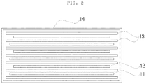
- FIG. 2 shows a cross-sectional view taken along A-A' of FIG. 1 of the stack type secondary battery according to an exemplary embodiment of the present invention.
- a secondary battery 10 includes an electrode assembly in which a plurality of anode plates 11, cathode plates 12, and separators 13 are stacked, a case 14 receives the electrode assembly, and the secondary battery is used in places where the batteries are required, such as a mobile phone, an electric vehicle, and the like.
- the secondary battery 10 As shown in FIG. 2 , in the secondary battery 10, a position where the anode plates 11, the cathode plates 12, and the separators 13 are stacked and aligned with one another is very important. It is determined that the secondary battery 10 is defective when the anode plates 11, the cathode plates 12, and the separators 13 are misaligned in the stacking process. Use of the defective secondary battery may cause a short-circuit, which may lead to a fire.
- FIG. 3 shows a schematic view of an electrode plate aligned state inspection system according to an exemplary embodiment of the present invention.
- the stacking process of the anode plates 11, the cathode plates 12, and the separators 13 is performed on a stack table 100.
- An upper lighting 200a is installed above the stack table 100 and a lower lighting 200b is installed below the stack table 100.
- a plurality of upper lightings 200a and lower lightings 200b may be installed according to an operator's needs.
- An inspection unit 300 imaging the stacking process of the anode plates 11, the cathode plates 12, and the separators 13 and determining the aligned state of the anode plates 11, the cathode plates 12, and the separators 13 is further installed above the stack table 100.
- the inspection unit 300 is preferably installed to image vertices of the electrode assembly and a plurality of inspection units 300 may be installed so as to image all four vertices of the electrode assembly.
- a height of the stack table 100 or the inspection 300 may be adjustable.
- the anode plates 11, the cathode plates 12, and the separators 13 are stacked on the stack table 100. Since a range to be imaged by the inspection unit 300 is gradually reduced as a height of the electrode assembly increases, errors may occur.
- the height of the stack table 100 or the inspection unit 300 is automatically adjusted by the height of the electrode assembly so that the inspection unit 300 may always image a certain region.
- the separator 13, the anode plate 11, the separator 13, and the cathode plate 12 are sequentially stacked as shown in FIG. 3 , but the stacking order is not limited.
- anode plate 11 and the cathode plate 12 are preferably alternately and sequentially stacked and the separator 13 needs to be interposed between the anode plate 11 and the cathode plate 12.
- the separator 13 may be supplied in a zigzag form rather than a plate form, and the supply form may be appropriately selected depending on a work environment by the operator.
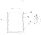
- FIGS. 4 and 5 show a plan view of a stack type secondary battery according to another exemplary embodiment of the present invention.
- FIG. 4 shows an example in which the anode plates 11, the cathode plates 12, and the separators 13 are aligned at a predetermined position.
- FIG. 5 shows an example in which it is determined that the secondary battery is defective due to a misalignment of the stacked anode plates 11, cathode plates 12, and separators 13.
- the electrode assembly is formed by stacking the anode plate 11, the cathode plate 12, and the separator 13, and the inspection unit 300 images the vertices of the electrode assembly.
- the inspection unit 300 images the electrode assembly in which the anode plate 11, the cathode plate 12, and the separator 13 are stacked, inspects a relative position between the separator 13 and the anode plate 11, the separator 13 and the cathode plate 12, or the anode plate 11 and the cathode plate 12, and determines that the electrode assembly is defective when the relative position is misaligned by a predetermined distance or more.
- both a horizontal distance and a vertical distance between the anode plate 11 and the cathode plate 12 are d 1 .
- a horizontal distance and a vertical distance between the anode plate 11 and the separator 13 are equal to d 2
- a horizontal distance and a vertical distance between the cathode plate 12 and the separator 13 are equal to d 3 .
- a horizontal distance d 1 between the anode plate 11 and the cathode 12 is different from a vertical distance d 4 therebetween.
- a horizontal distance d 5 and a vertical distance d 2 between the anode plate 11 and the separator 13 are also different from each other, and a horizontal distance d 3 and a vertical distance d 6 between the cathode plate 12 and the separator 13 are also different from each other.
- the inspection unit 300 determines that the separator 13 and the anode plate 11, the separator 13 and the cathode plate 12, or the anode plate 11 and the cathode plate 12 are misaligned, and the stacking process of the electrode assembly is suspended by a controller.
- the inspection unit 300 not only inspects the relative position between the separator 13 and the anode plate 11, the separator 13 and the cathode plate 12, and the anode plate 11 and the cathode plate 12, but also calculates a value of a misaligned distance, and performs a cumulative calculation of the calculated value of the misaligned distance.
- the inspection unit 300 images the stacking process, and even in a case where a cumulative value of the misaligned distance is higher than a preset value, the stacking process of the electrode assembly is suspended by a controller.
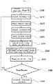
- FIG. 6 shows a flowchart of an electrode plate aligned state inspection system according to an exemplary embodiment of the present invention.
- a first separator stacking step S110 of stacking one separator 13 on the stack table 100 a first electrode plate stacking step S120 of stacking the anode plate 11 on the separator stacked in the first separator stacking step S110, a second separator stacking step S130 of stacking another separator 13 on the anode plate 11 stacked in the first separator stacking step S120, and a second electrode stacking step S140 of stacking the anode plate 11 on the another separator 13 stacked in the second separator stacking step S130 are performed.
- the cathode plates 12 may be stacked in the first electrode plate stacking step S120, and the anode plates 11 may be stacked in the second electrode plate stacking step S140, but the electrode plates to be stacked in the first electrode plate stacking step S120 and the electrode plates to be stacked in the second electrode plate stacking step S140 need to be different from each other.
- the anode plate 11 stacked in the first electrode plate stacking step S120 may not be imaged by the inspection unit 300 due to the separator 13 stacked in the second separator stacking step S130.
- lighting units 200 including an upper lighting 200a and a lower lighting 200b are installed above and below the stack table 100, respectively. Since a material of the separator 13 is a material transmitting light therethrough, the inspection unit 300 may inspect the aligned state of the anode plate 11.
- the first separator stacking step S110 is performed to continue the stacking process of the electrode assembly.
- a suspending step S170 of suspending the stacking process is performed when the anode plate 11, the cathode plate 12, and the separator 13 are misaligned.
- the electrode plate aligned state inspection system of the present invention may inspect the aligned state of the anode plate 11, the cathode plate 12, and the separator 13 per unit stacking process, such that it is possible to determine that the electrode assembly is defective or not in the stacking process and take corresponding measures for the defect.
- FIG. 7 shows a flowchart of an electrode plate aligned state inspection system according to another exemplary embodiment of the present invention. Similar to the first exemplary embodiment described above, after an imaging step S200 of starting imaging by the inspection unit 300 before starting the stacking process of the electrode assembly is performed, a first separator stacking step S210 of stacking one separator 13 on the stack table 100, a first electrode plate stacking step S220 of stacking the anode plate 11 on the separator stacked in the first separator stacking step S210, a second separator stacking step S230 of stacking another separator 13 on the anode plate 11 stacked in the first electrode plate stacking step S220, and a second electrode stacking step S240 of stacking the anode plate 11 on the another separator 13 stacked in the second separator stacking step S230 are performed.
- the cathode plates 12 may be stacked in the first electrode plate stacking step S220, and the anode plates 11 may be stacked in the second electrode plate stacking step S240, but the electrode plates to be stacked in the first electrode plate stacking step S220 and the electrode plates to be stacked in the second electrode plate stacking step S240 need to be different from each other.
- the anode plate 11 stacked in the first electrode plate stacking step S220 may not be imaged by the inspection unit 300 due to the separator 13 stacked in the second separator stacking step S230.
- lighting units 200 including an upper lighting 200a and a lower lighting 200b are installed above and below the stack table 100, respectively. Since a material of the separator 13 is a material transmitting light therethrough, the inspection unit 300 may inspect the aligned state of the anode plate 11.
- a measurement step S260 of measuring a value of a misalignment between the anode plate 11, the cathode plate 12, and the separator 13 is performed by the inspection unit 300.
- a calculating step S270 of performing cumulative calculation of the value of the misalignment is performed.
- X total is a total sum of the values of the misalignment. It is preferable that X total is set to zero in the imaging step S200.
- a second determining step S280 of comparing the total sum of the values of the misalignment X total with a preset value X standard is performed.
- the first separator stacking step S210 is performed so as to continue the electrode assembly stacking process.
- the value of X total is initialized when the stacking process is resumed after the stacking process is suspended in the suspending step S290 and then the corresponding measures for the defect are taken.
- first separator stacking step S210 to the second electrode plate stacking step S240 are one unit stacking process, and the electrode assembly stacked through the unit stacking process is a unit electrode assembly.
- a value of a misalignment of the one unit electrode assembly is 7, it is determined that the electrode assembly is not defective and the stacking process is continued. Then, when a unit electrode assembly having a value of a misalignment of 4 is stacked on the unit electrode assembly having the value of the misalignment of 7, since the value of the misalignment is 4, it is determined that the electrode assembly is not defective.
- the electrode assembly is not defective due to the value of the misalignment of less than 10.
- the completed electrode assembly is defective in the final defect inspection due to the misalignment of the stacked electrode assemblies and the electrode assembly is discarded in a completed state.
- a safety accident may occur when it is determined that the electrode assembly is not defective in the final defect inspection.
- values of a misalignment of the unit electrode assembly are accumulated.
- the unit electrode assembly having the value of the misalignment of 4 is stacked on the unit electrode assembly having the value of the misalignment of 7, since X total which is a total sum of the values of the misalignment exceeds 10, it is determined that the electrode assembly is defective.
- the electrode plate aligned state inspection system may inspect the aligned state of the anode plate 11, the cathode plate 12, and the separator 13 for each unit stacking process, such that it is possible to determine whether or not the electrode assembly is defective during a stacking process of the electrode assembly and take corresponding measures for the defect.
- the electrode plate aligned state inspection method according to the first exemplary embodiment and the electrode plate aligned state inspection method according to the second exemplary embodiment are separately described in order to describe the electrode plate aligned state inspection method of the present invention in more detail, and the first exemplary embodiment and the second exemplary embodiment may be used in combination to inspect the aligned state of the electrode plate.
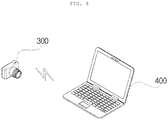
- the stacking process is suspended, and video data obtained by the imaging performed by the inspection unit 300 is automatically stored in the storage unit 400 separately provided.
- the storage unit 400 will be described in more detail.
- FIG. 8 is a schematic view of an inspection unit and a storage unit of an electrode plate aligned state inspection system according to an exemplary embodiment of the present invention. As shown in FIG. 8 , the inspection unit 300 and the storage unit 400 are electrically connected to each other, and the storage unit 400 receives the video data obtained by the imaging performed by the inspection unit 300.
- the electrode plate aligned state inspection system of the present invention having the above-mentioned configuration may improve the quality reliability of the electrode assembly because the operator may immediately recognize an occurrence of a misalignment when the misalignment occurs during the stacking process of the cathode plate, the anode plate, and the separator.
- the video data obtained by the imaging of the production process of the electrode assembly is automatically stored, and therefore, the data may be used as data that may be checked later when the quality is checked and the defective product is produced.
Landscapes
- Engineering & Computer Science (AREA)
- Chemical & Material Sciences (AREA)
- Manufacturing & Machinery (AREA)
- Chemical Kinetics & Catalysis (AREA)
- Electrochemistry (AREA)
- General Chemical & Material Sciences (AREA)
- General Physics & Mathematics (AREA)
- Physics & Mathematics (AREA)
- Health & Medical Sciences (AREA)
- Life Sciences & Earth Sciences (AREA)
- Analytical Chemistry (AREA)
- Biochemistry (AREA)
- General Health & Medical Sciences (AREA)
- Immunology (AREA)
- Pathology (AREA)
- Quality & Reliability (AREA)
- Computer Vision & Pattern Recognition (AREA)
- Theoretical Computer Science (AREA)
- Secondary Cells (AREA)
Applications Claiming Priority (1)
| Application Number | Priority Date | Filing Date | Title |
|---|---|---|---|
| KR1020180050508A KR102629119B1 (ko) | 2018-05-02 | 2018-05-02 | 전극판 정렬 상태 검사 시스템 및 방법 |
Publications (2)
| Publication Number | Publication Date |
|---|---|
| EP3565052A1 true EP3565052A1 (fr) | 2019-11-06 |
| EP3565052B1 EP3565052B1 (fr) | 2023-12-20 |
Family
ID=66334267
Family Applications (1)
| Application Number | Title | Priority Date | Filing Date |
|---|---|---|---|
| EP19171785.9A Active EP3565052B1 (fr) | 2018-05-02 | 2019-04-30 | Système et procédé d'inspection de l'état d'alignement d'une plaque d'électrode |
Country Status (6)
| Country | Link |
|---|---|
| US (1) | US10957944B2 (fr) |
| EP (1) | EP3565052B1 (fr) |
| KR (1) | KR102629119B1 (fr) |
| CN (1) | CN110441325B (fr) |
| DE (1) | DE202019005977U1 (fr) |
| PL (1) | PL3565052T3 (fr) |
Cited By (1)
| Publication number | Priority date | Publication date | Assignee | Title |
|---|---|---|---|---|
| EP4027424A1 (fr) * | 2021-01-07 | 2022-07-13 | SK On Co., Ltd. | Appareil d'inspection d'empilement d'électrodes de batterie secondaire et son procédé d'inspection |
Families Citing this family (11)
| Publication number | Priority date | Publication date | Assignee | Title |
|---|---|---|---|---|
| US20230006239A1 (en) * | 2019-12-06 | 2023-01-05 | Lg Energy Solution, Ltd. | Apparatus and Method for Manufacturing Electrode Assembly and Method for Manufacturing Secondary Battery Comprising the Same |
| KR102274922B1 (ko) * | 2019-12-27 | 2021-07-08 | (주) 인텍플러스 | 슬릿빔을 이용한 배터리 외관 검사장치 |
| JP2022117018A (ja) * | 2021-01-29 | 2022-08-10 | トヨタ自動車株式会社 | 積層電極体、樹脂固定積層電極体、及び全固体電池 |
| KR20220166098A (ko) * | 2021-06-09 | 2022-12-16 | 주식회사 엘지에너지솔루션 | 전극판 또는 단위셀 적층 검사 장치 |
| KR20230059584A (ko) * | 2021-10-26 | 2023-05-03 | 주식회사 엘지에너지솔루션 | 전극 조립체의 제조방법 |
| KR20230095557A (ko) * | 2021-12-22 | 2023-06-29 | 주식회사 엘지에너지솔루션 | 배터리 셀 검사 시스템 및 방법 |
| WO2023128661A1 (fr) * | 2021-12-29 | 2023-07-06 | 에스케이온 주식회사 | Appareil et procédé d'inspection d'alignement d'ensemble électrode |
| DE102022104471A1 (de) * | 2022-02-24 | 2023-08-24 | Körber Technologies Gmbh | Messvorrichtung zur Vermessung der Ausrichtung und/oder Orientierung von Segmenten der Energiezellen produzierenden Industrie und Verfahren zur Herstellung von Segmenten |
| CN115824062A (zh) * | 2022-03-30 | 2023-03-21 | 宁德时代新能源科技股份有限公司 | 尺寸检测装置及检测方法、叠片设备 |
| KR20230161686A (ko) * | 2022-05-19 | 2023-11-28 | 주식회사 필로포스 | 광간섭 단층촬영 기반 이차전지 정렬상태 검사 방법 및 시스템 |
| CN115385167B (zh) * | 2022-09-29 | 2023-08-25 | 广州市易鸿智能装备有限公司 | 一种锂电池智能匹配物料的系统及方法 |
Citations (3)
| Publication number | Priority date | Publication date | Assignee | Title |
|---|---|---|---|---|
| JP2013143213A (ja) * | 2012-01-10 | 2013-07-22 | Ckd Corp | 積層電池の製造過程に用いられる検査装置 |
| US9046352B2 (en) * | 2011-04-07 | 2015-06-02 | Nissan Motor Co., Ltd. | Electrode position detection device and electrode position detection method |
| KR101699809B1 (ko) | 2014-12-03 | 2017-01-25 | 도시바 아이티 앤 콘트롤 시스템 가부시키가이샤 | 전지 검사 장치 |
Family Cites Families (18)
| Publication number | Priority date | Publication date | Assignee | Title |
|---|---|---|---|---|
| JP2833402B2 (ja) * | 1993-03-02 | 1998-12-09 | ジェイエスアール株式会社 | 被検査電極板の検査方法 |
| KR100388648B1 (ko) * | 2001-05-23 | 2003-06-25 | 주식회사 코캄엔지니어링 | 자동화된 리튬 2차전지 제조 시스템 |
| KR100987300B1 (ko) * | 2007-07-04 | 2010-10-12 | 주식회사 엘지화학 | 스택-폴딩형 전극조립체 및 그것의 제조방법 |
| JP5438368B2 (ja) | 2009-04-28 | 2014-03-12 | Ckd株式会社 | 積層電池の製造過程に用いられる検査装置 |
| CN201681057U (zh) * | 2009-10-21 | 2010-12-22 | 精浚科技股份有限公司 | 电池检测装置 |
| KR101084075B1 (ko) * | 2009-11-03 | 2011-11-16 | 삼성에스디아이 주식회사 | 이차전지 및 그 제조방법 |
| KR101223629B1 (ko) * | 2010-09-03 | 2013-01-17 | 삼성에스디아이 주식회사 | 권취기, 빗 감김 검사 시스템 및 검사방법 |
| JP2012248465A (ja) * | 2011-05-30 | 2012-12-13 | Sharp Corp | 二次電池およびその製造方法 |
| JP5988474B2 (ja) * | 2012-03-01 | 2016-09-07 | 東レエンジニアリング株式会社 | 積層シート材料の端面を検査する装置 |
| JP6158789B2 (ja) * | 2012-03-30 | 2017-07-05 | 三洋電機株式会社 | 積層式電池 |
| JP6055389B2 (ja) * | 2013-10-08 | 2016-12-27 | 株式会社Nttドコモ | 無線基地局 |
| KR102273780B1 (ko) * | 2014-07-04 | 2021-07-06 | 삼성에스디아이 주식회사 | 이차 전지, 이차 전지의 제조 장치 및 이차 전지의 제조 방법 |
| JP6344122B2 (ja) * | 2014-07-31 | 2018-06-20 | 株式会社村田製作所 | 位置補正/搬送ステージ装置及び位置補正/搬送ステージの補正方法 |
| CN107112578B (zh) | 2015-01-13 | 2019-07-05 | 艾利电力能源有限公司 | 电极层叠体中的电极板的位置偏移检测方法以及其装置 |
| WO2016117180A1 (fr) * | 2015-01-21 | 2016-07-28 | 三菱電機株式会社 | Élément de batterie solaire, module de batterie solaire, procédé de fabrication d'un élément de batterie solaire, et procédé de fabrication d'un module de batterie solaire |
| KR101684550B1 (ko) * | 2015-07-29 | 2016-12-08 | 현대자동차 주식회사 | 연료전지용 막-전극 어셈블리의 제조장치 및 방법 |
| JP6744130B2 (ja) * | 2016-05-26 | 2020-08-19 | 住友化学株式会社 | 有機デバイスの製造方法 |
| KR102217201B1 (ko) * | 2018-03-29 | 2021-02-18 | 주식회사 엘지화학 | 전극조립체의 얼라인 검사 장치 및 그를 이용한 전극조립체의 얼라인 검사 방법 |
-
2018
- 2018-05-02 KR KR1020180050508A patent/KR102629119B1/ko active IP Right Grant
-
2019
- 2019-04-30 DE DE202019005977.6U patent/DE202019005977U1/de active Active
- 2019-04-30 CN CN201910362295.XA patent/CN110441325B/zh active Active
- 2019-04-30 EP EP19171785.9A patent/EP3565052B1/fr active Active
- 2019-04-30 PL PL19171785.9T patent/PL3565052T3/pl unknown
- 2019-04-30 US US16/399,480 patent/US10957944B2/en active Active
Patent Citations (3)
| Publication number | Priority date | Publication date | Assignee | Title |
|---|---|---|---|---|
| US9046352B2 (en) * | 2011-04-07 | 2015-06-02 | Nissan Motor Co., Ltd. | Electrode position detection device and electrode position detection method |
| JP2013143213A (ja) * | 2012-01-10 | 2013-07-22 | Ckd Corp | 積層電池の製造過程に用いられる検査装置 |
| KR101699809B1 (ko) | 2014-12-03 | 2017-01-25 | 도시바 아이티 앤 콘트롤 시스템 가부시키가이샤 | 전지 검사 장치 |
Cited By (1)
| Publication number | Priority date | Publication date | Assignee | Title |
|---|---|---|---|---|
| EP4027424A1 (fr) * | 2021-01-07 | 2022-07-13 | SK On Co., Ltd. | Appareil d'inspection d'empilement d'électrodes de batterie secondaire et son procédé d'inspection |
Also Published As
| Publication number | Publication date |
|---|---|
| EP3565052B1 (fr) | 2023-12-20 |
| CN110441325A (zh) | 2019-11-12 |
| PL3565052T3 (pl) | 2024-05-13 |
| DE202019005977U1 (de) | 2023-10-09 |
| KR20190126524A (ko) | 2019-11-12 |
| US20190341658A1 (en) | 2019-11-07 |
| US10957944B2 (en) | 2021-03-23 |
| KR102629119B1 (ko) | 2024-01-26 |
| CN110441325B (zh) | 2023-11-07 |
Similar Documents
| Publication | Publication Date | Title |
|---|---|---|
| EP3565052B1 (fr) | Système et procédé d'inspection de l'état d'alignement d'une plaque d'électrode | |
| JP2009004389A (ja) | 電池の検査方法 | |
| CN111024008B (zh) | 一种叠片型储能器件的错位尺寸的检测方法及检测装置 | |
| JP4529364B2 (ja) | 円筒形電池の検査方法 | |
| JP4048905B2 (ja) | 電池の検査方法 | |
| CN112670546A (zh) | 具有多机型视觉检查功能的二次电池制造装置 | |
| KR102287768B1 (ko) | 전극 조립체 제조방법 및 이차전지 제조방법 | |
| CN117630021B (zh) | 焊接检测装置及焊接检测方法 | |
| JP4720221B2 (ja) | 二次電池の製造方法 | |
| KR102130027B1 (ko) | 전극의 오정렬 검출 시스템 및 방법 | |
| KR20150033268A (ko) | 이차전지의 초음파 용접상태에 관한 비전측정 최적화방법 및 그 장치 | |
| EP4123778A1 (fr) | Appareil d'inspection d'empilement pour plaque d'électrode ou cellule unitaire | |
| KR20200053784A (ko) | 전지셀의 전극 탭 접힘 불량 판별 시스템 및 그 방법 | |
| JP2019049479A (ja) | 二次電池状態判定方法及び二次電池状態判定装置 | |
| KR20220102495A (ko) | 이차 전지 제조 방법 | |
| EP4199209A1 (fr) | Procédé de détection de mauvais assemblage ou de mauvais alignement pendant le fonctionnement d'un plateau interne, et plateau d'activation d'élément de batterie | |
| JP2023089452A (ja) | 電池モジュールの検査方法 | |
| EP4372855A1 (fr) | Procédé de fabrication d'ensemble électrode | |
| EP4310986A1 (fr) | Appareil d'inspection d'état de liaison et procédé d'inspection d'état de liaison l'utilisant | |
| US11841328B2 (en) | Method and device for testing electrode sheet | |
| US20240103096A1 (en) | Method for inspecting a power storage device, method for manufacturing a power storage device, and method for manufacturing a device stack | |
| US20230223509A1 (en) | Electrode Assembly Comprising Anode Sheet and Anode Having Improved Stacking Characteristics of Electrode, and Method of Manufacturing the Same | |
| KR101778348B1 (ko) | 이차 전지의 용량 측정 시스템 및 측정 방법 | |
| KR20230151293A (ko) | 용접 품질 검사 방법 | |
| KR20230058836A (ko) | 용접부 검사장치 및 이를 이용한 용접부 검사방법 |
Legal Events
| Date | Code | Title | Description |
|---|---|---|---|
| REG | Reference to a national code |
Ref country code: DE Ref legal event code: R138 Ref document number: 202019005977 Country of ref document: DE Free format text: GERMAN DOCUMENT NUMBER IS 602019043475 |
|
| PUAI | Public reference made under article 153(3) epc to a published international application that has entered the european phase |
Free format text: ORIGINAL CODE: 0009012 |
|
| STAA | Information on the status of an ep patent application or granted ep patent |
Free format text: STATUS: REQUEST FOR EXAMINATION WAS MADE |
|
| 17P | Request for examination filed |
Effective date: 20190430 |
|
| AK | Designated contracting states |
Kind code of ref document: A1 Designated state(s): AL AT BE BG CH CY CZ DE DK EE ES FI FR GB GR HR HU IE IS IT LI LT LU LV MC MK MT NL NO PL PT RO RS SE SI SK SM TR |
|
| AX | Request for extension of the european patent |
Extension state: BA ME |
|
| TPAC | Observations filed by third parties |
Free format text: ORIGINAL CODE: EPIDOSNTIPA |
|
| STAA | Information on the status of an ep patent application or granted ep patent |
Free format text: STATUS: EXAMINATION IS IN PROGRESS |
|
| 17Q | First examination report despatched |
Effective date: 20220124 |
|
| RAP1 | Party data changed (applicant data changed or rights of an application transferred) |
Owner name: SK ON CO., LTD. |
|
| REG | Reference to a national code |
Ref legal event code: R079 Ref document number: 602019043475 Country of ref document: DE Ref country code: DE Free format text: PREVIOUS MAIN CLASS: H01M0010052000 Ipc: G01B0011020000 |
|
| GRAP | Despatch of communication of intention to grant a patent |
Free format text: ORIGINAL CODE: EPIDOSNIGR1 |
|
| STAA | Information on the status of an ep patent application or granted ep patent |
Free format text: STATUS: GRANT OF PATENT IS INTENDED |
|
| RIC1 | Information provided on ipc code assigned before grant |
Ipc: G01B 11/00 20060101ALI20230526BHEP Ipc: H01M 10/04 20060101ALI20230526BHEP Ipc: H01M 10/0585 20100101ALI20230526BHEP Ipc: H01M 10/052 20100101ALI20230526BHEP Ipc: G01B 11/02 20060101AFI20230526BHEP |
|
| P01 | Opt-out of the competence of the unified patent court (upc) registered |
Effective date: 20230602 |
|
| INTG | Intention to grant announced |
Effective date: 20230629 |
|
| GRAS | Grant fee paid |
Free format text: ORIGINAL CODE: EPIDOSNIGR3 |
|
| GRAA | (expected) grant |
Free format text: ORIGINAL CODE: 0009210 |
|
| STAA | Information on the status of an ep patent application or granted ep patent |
Free format text: STATUS: THE PATENT HAS BEEN GRANTED |
|
| AK | Designated contracting states |
Kind code of ref document: B1 Designated state(s): AL AT BE BG CH CY CZ DE DK EE ES FI FR GB GR HR HU IE IS IT LI LT LU LV MC MK MT NL NO PL PT RO RS SE SI SK SM TR |
|
| REG | Reference to a national code |
Ref country code: GB Ref legal event code: FG4D |
|
| REG | Reference to a national code |
Ref country code: CH Ref legal event code: EP |
|
| REG | Reference to a national code |
Ref country code: DE Ref legal event code: R096 Ref document number: 602019043475 Country of ref document: DE |
|
| REG | Reference to a national code |
Ref country code: IE Ref legal event code: FG4D |
|
| PG25 | Lapsed in a contracting state [announced via postgrant information from national office to epo] |
Ref country code: GR Free format text: LAPSE BECAUSE OF FAILURE TO SUBMIT A TRANSLATION OF THE DESCRIPTION OR TO PAY THE FEE WITHIN THE PRESCRIBED TIME-LIMIT Effective date: 20240321 |
|
| REG | Reference to a national code |
Ref country code: LT Ref legal event code: MG9D |
|
| PG25 | Lapsed in a contracting state [announced via postgrant information from national office to epo] |
Ref country code: LT Free format text: LAPSE BECAUSE OF FAILURE TO SUBMIT A TRANSLATION OF THE DESCRIPTION OR TO PAY THE FEE WITHIN THE PRESCRIBED TIME-LIMIT Effective date: 20231220 |
|
| REG | Reference to a national code |
Ref country code: NL Ref legal event code: MP Effective date: 20231220 |
|
| PG25 | Lapsed in a contracting state [announced via postgrant information from national office to epo] |
Ref country code: ES Free format text: LAPSE BECAUSE OF FAILURE TO SUBMIT A TRANSLATION OF THE DESCRIPTION OR TO PAY THE FEE WITHIN THE PRESCRIBED TIME-LIMIT Effective date: 20231220 |
|
| PG25 | Lapsed in a contracting state [announced via postgrant information from national office to epo] |
Ref country code: LT Free format text: LAPSE BECAUSE OF FAILURE TO SUBMIT A TRANSLATION OF THE DESCRIPTION OR TO PAY THE FEE WITHIN THE PRESCRIBED TIME-LIMIT Effective date: 20231220 Ref country code: GR Free format text: LAPSE BECAUSE OF FAILURE TO SUBMIT A TRANSLATION OF THE DESCRIPTION OR TO PAY THE FEE WITHIN THE PRESCRIBED TIME-LIMIT Effective date: 20240321 Ref country code: FI Free format text: LAPSE BECAUSE OF FAILURE TO SUBMIT A TRANSLATION OF THE DESCRIPTION OR TO PAY THE FEE WITHIN THE PRESCRIBED TIME-LIMIT Effective date: 20231220 Ref country code: ES Free format text: LAPSE BECAUSE OF FAILURE TO SUBMIT A TRANSLATION OF THE DESCRIPTION OR TO PAY THE FEE WITHIN THE PRESCRIBED TIME-LIMIT Effective date: 20231220 Ref country code: BG Free format text: LAPSE BECAUSE OF FAILURE TO SUBMIT A TRANSLATION OF THE DESCRIPTION OR TO PAY THE FEE WITHIN THE PRESCRIBED TIME-LIMIT Effective date: 20240320 |
|
| REG | Reference to a national code |
Ref country code: AT Ref legal event code: MK05 Ref document number: 1642803 Country of ref document: AT Kind code of ref document: T Effective date: 20231220 |
|
| PG25 | Lapsed in a contracting state [announced via postgrant information from national office to epo] |
Ref country code: NL Free format text: LAPSE BECAUSE OF FAILURE TO SUBMIT A TRANSLATION OF THE DESCRIPTION OR TO PAY THE FEE WITHIN THE PRESCRIBED TIME-LIMIT Effective date: 20231220 |