EP3564590B1 - Luftdruckregler des variablen typs für einen expansionstank - Google Patents
Luftdruckregler des variablen typs für einen expansionstank Download PDFInfo
- Publication number
- EP3564590B1 EP3564590B1 EP17888787.3A EP17888787A EP3564590B1 EP 3564590 B1 EP3564590 B1 EP 3564590B1 EP 17888787 A EP17888787 A EP 17888787A EP 3564590 B1 EP3564590 B1 EP 3564590B1
- Authority
- EP
- European Patent Office
- Prior art keywords
- expansion tank
- flow path
- pressure
- air
- variable
- Prior art date
- Legal status (The legal status is an assumption and is not a legal conclusion. Google has not performed a legal analysis and makes no representation as to the accuracy of the status listed.)
- Active
Links
Images


Classifications
-
- F—MECHANICAL ENGINEERING; LIGHTING; HEATING; WEAPONS; BLASTING
- F24—HEATING; RANGES; VENTILATING
- F24D—DOMESTIC- OR SPACE-HEATING SYSTEMS, e.g. CENTRAL HEATING SYSTEMS; DOMESTIC HOT-WATER SUPPLY SYSTEMS; ELEMENTS OR COMPONENTS THEREFOR
- F24D19/00—Details
- F24D19/10—Arrangement or mounting of control or safety devices
- F24D19/1006—Arrangement or mounting of control or safety devices for water heating systems
- F24D19/1009—Arrangement or mounting of control or safety devices for water heating systems for central heating
- F24D19/1015—Arrangement or mounting of control or safety devices for water heating systems for central heating using a valve or valves
- F24D19/1036—Having differential pressure measurement facilities
-
- F—MECHANICAL ENGINEERING; LIGHTING; HEATING; WEAPONS; BLASTING
- F16—ENGINEERING ELEMENTS AND UNITS; GENERAL MEASURES FOR PRODUCING AND MAINTAINING EFFECTIVE FUNCTIONING OF MACHINES OR INSTALLATIONS; THERMAL INSULATION IN GENERAL
- F16K—VALVES; TAPS; COCKS; ACTUATING-FLOATS; DEVICES FOR VENTING OR AERATING
- F16K11/00—Multiple-way valves, e.g. mixing valves; Pipe fittings incorporating such valves
- F16K11/02—Multiple-way valves, e.g. mixing valves; Pipe fittings incorporating such valves with all movable sealing faces moving as one unit
- F16K11/08—Multiple-way valves, e.g. mixing valves; Pipe fittings incorporating such valves with all movable sealing faces moving as one unit comprising only taps or cocks
- F16K11/087—Multiple-way valves, e.g. mixing valves; Pipe fittings incorporating such valves with all movable sealing faces moving as one unit comprising only taps or cocks with spherical plug
- F16K11/0873—Multiple-way valves, e.g. mixing valves; Pipe fittings incorporating such valves with all movable sealing faces moving as one unit comprising only taps or cocks with spherical plug the plug being only rotatable around one spindle
-
- F—MECHANICAL ENGINEERING; LIGHTING; HEATING; WEAPONS; BLASTING
- F16—ENGINEERING ELEMENTS AND UNITS; GENERAL MEASURES FOR PRODUCING AND MAINTAINING EFFECTIVE FUNCTIONING OF MACHINES OR INSTALLATIONS; THERMAL INSULATION IN GENERAL
- F16K—VALVES; TAPS; COCKS; ACTUATING-FLOATS; DEVICES FOR VENTING OR AERATING
- F16K31/00—Actuating devices; Operating means; Releasing devices
- F16K31/44—Mechanical actuating means
- F16K31/60—Handles
- F16K31/602—Pivoting levers, e.g. single-sided
-
- F—MECHANICAL ENGINEERING; LIGHTING; HEATING; WEAPONS; BLASTING
- F24—HEATING; RANGES; VENTILATING
- F24D—DOMESTIC- OR SPACE-HEATING SYSTEMS, e.g. CENTRAL HEATING SYSTEMS; DOMESTIC HOT-WATER SUPPLY SYSTEMS; ELEMENTS OR COMPONENTS THEREFOR
- F24D1/00—Steam central heating systems
- F24D1/08—Feed-line arrangements, e.g. providing for heat-accumulator tanks, expansion tanks
-
- F—MECHANICAL ENGINEERING; LIGHTING; HEATING; WEAPONS; BLASTING
- F24—HEATING; RANGES; VENTILATING
- F24D—DOMESTIC- OR SPACE-HEATING SYSTEMS, e.g. CENTRAL HEATING SYSTEMS; DOMESTIC HOT-WATER SUPPLY SYSTEMS; ELEMENTS OR COMPONENTS THEREFOR
- F24D19/00—Details
- F24D19/08—Arrangements for drainage, venting or aerating
- F24D19/082—Arrangements for drainage, venting or aerating for water heating systems
- F24D19/083—Venting arrangements
-
- F—MECHANICAL ENGINEERING; LIGHTING; HEATING; WEAPONS; BLASTING
- F24—HEATING; RANGES; VENTILATING
- F24D—DOMESTIC- OR SPACE-HEATING SYSTEMS, e.g. CENTRAL HEATING SYSTEMS; DOMESTIC HOT-WATER SUPPLY SYSTEMS; ELEMENTS OR COMPONENTS THEREFOR
- F24D19/00—Details
- F24D19/08—Arrangements for drainage, venting or aerating
- F24D19/082—Arrangements for drainage, venting or aerating for water heating systems
- F24D19/088—Draining arrangements
-
- F—MECHANICAL ENGINEERING; LIGHTING; HEATING; WEAPONS; BLASTING
- F24—HEATING; RANGES; VENTILATING
- F24D—DOMESTIC- OR SPACE-HEATING SYSTEMS, e.g. CENTRAL HEATING SYSTEMS; DOMESTIC HOT-WATER SUPPLY SYSTEMS; ELEMENTS OR COMPONENTS THEREFOR
- F24D3/00—Hot-water central heating systems
- F24D3/02—Hot-water central heating systems with forced circulation, e.g. by pumps
-
- F—MECHANICAL ENGINEERING; LIGHTING; HEATING; WEAPONS; BLASTING
- F24—HEATING; RANGES; VENTILATING
- F24D—DOMESTIC- OR SPACE-HEATING SYSTEMS, e.g. CENTRAL HEATING SYSTEMS; DOMESTIC HOT-WATER SUPPLY SYSTEMS; ELEMENTS OR COMPONENTS THEREFOR
- F24D3/00—Hot-water central heating systems
- F24D3/10—Feed-line arrangements, e.g. providing for heat-accumulator tanks, expansion tanks ; Hydraulic components of a central heating system
- F24D3/1008—Feed-line arrangements, e.g. providing for heat-accumulator tanks, expansion tanks ; Hydraulic components of a central heating system expansion tanks
- F24D3/1016—Tanks having a bladder
-
- F—MECHANICAL ENGINEERING; LIGHTING; HEATING; WEAPONS; BLASTING
- F24—HEATING; RANGES; VENTILATING
- F24H—FLUID HEATERS, e.g. WATER OR AIR HEATERS, HAVING HEAT-GENERATING MEANS, e.g. HEAT PUMPS, IN GENERAL
- F24H1/00—Water heaters, e.g. boilers, continuous-flow heaters or water-storage heaters
- F24H1/18—Water-storage heaters
- F24H1/188—Water-storage heaters with means for compensating water expansion
-
- F—MECHANICAL ENGINEERING; LIGHTING; HEATING; WEAPONS; BLASTING
- F16—ENGINEERING ELEMENTS AND UNITS; GENERAL MEASURES FOR PRODUCING AND MAINTAINING EFFECTIVE FUNCTIONING OF MACHINES OR INSTALLATIONS; THERMAL INSULATION IN GENERAL
- F16L—PIPES; JOINTS OR FITTINGS FOR PIPES; SUPPORTS FOR PIPES, CABLES OR PROTECTIVE TUBING; MEANS FOR THERMAL INSULATION IN GENERAL
- F16L55/00—Devices or appurtenances for use in, or in connection with, pipes or pipe systems
- F16L55/04—Devices damping pulsations or vibrations in fluids
- F16L55/045—Devices damping pulsations or vibrations in fluids specially adapted to prevent or minimise the effects of water hammer
- F16L55/05—Buffers therefor
-
- F—MECHANICAL ENGINEERING; LIGHTING; HEATING; WEAPONS; BLASTING
- F24—HEATING; RANGES; VENTILATING
- F24D—DOMESTIC- OR SPACE-HEATING SYSTEMS, e.g. CENTRAL HEATING SYSTEMS; DOMESTIC HOT-WATER SUPPLY SYSTEMS; ELEMENTS OR COMPONENTS THEREFOR
- F24D2220/00—Components of central heating installations excluding heat sources
- F24D2220/02—Fluid distribution means
- F24D2220/0235—Three-way-valves
-
- F—MECHANICAL ENGINEERING; LIGHTING; HEATING; WEAPONS; BLASTING
- F24—HEATING; RANGES; VENTILATING
- F24D—DOMESTIC- OR SPACE-HEATING SYSTEMS, e.g. CENTRAL HEATING SYSTEMS; DOMESTIC HOT-WATER SUPPLY SYSTEMS; ELEMENTS OR COMPONENTS THEREFOR
- F24D2220/00—Components of central heating installations excluding heat sources
- F24D2220/02—Fluid distribution means
- F24D2220/0271—Valves
-
- F—MECHANICAL ENGINEERING; LIGHTING; HEATING; WEAPONS; BLASTING
- F24—HEATING; RANGES; VENTILATING
- F24D—DOMESTIC- OR SPACE-HEATING SYSTEMS, e.g. CENTRAL HEATING SYSTEMS; DOMESTIC HOT-WATER SUPPLY SYSTEMS; ELEMENTS OR COMPONENTS THEREFOR
- F24D2220/00—Components of central heating installations excluding heat sources
- F24D2220/02—Fluid distribution means
- F24D2220/0278—Expansion vessels
-
- F—MECHANICAL ENGINEERING; LIGHTING; HEATING; WEAPONS; BLASTING
- F24—HEATING; RANGES; VENTILATING
- F24D—DOMESTIC- OR SPACE-HEATING SYSTEMS, e.g. CENTRAL HEATING SYSTEMS; DOMESTIC HOT-WATER SUPPLY SYSTEMS; ELEMENTS OR COMPONENTS THEREFOR
- F24D2220/00—Components of central heating installations excluding heat sources
- F24D2220/04—Sensors
- F24D2220/046—Pressure sensors
Definitions
- the present invention relates to an air pressure regulating device, and more particularly to an air pressure regulating device for an expansion tank capable of displaying a pressure of an expansion tank and regulating the pressure of the expansion tank according to a displayed pressure.
- the fluid pipe may be a cooling/heating pipe, a cold/hot water pipe, and the like.
- temperature, pressure, and volume of the fluid transferred in the pipe are changed according to use situation, surrounding environment, weather, temperature, or the like, and thus, there is a problem in that surging occurs in the fluid pipe according to such a change or the fluid pipe is damaged.
- the technique of connecting the pumps in parallel has a problem in that the installation cost is greatly increased and the surging is not effectively reduced.
- the air chamber in order to perform a practical operation, the air chamber needs be installed at the top of the pipe, and thus, a connector is frequently broken by vibration of the air chamber during the operation of the pump, so that it is difficult to apply the technique itself.
- Patent Document 1 Korean Patent No. 10-0489554 discloses a surging reduction apparatus having a configuration in which an elastic airbag is provided to compart the air and the fluid by the airbag while effectively responding to the pressure, so that surging of the fluid pipe can be prevented by the air pressure of the airbag.
- US 6 089 837 A describes a pump inlet stabilizer for positive displacement reciprocating pumps.
- DE 196 10 598 A1 describes a device having a cut-off component which has through-passages and is located between an installation and a volume equalizing component.
- the present invention has been made to solve the above-mentioned problems, and an object of the present invention is to provide a variable air pressure regulating device for an expansion tank capable of actively responding to a change in pressure of a fluid flowing in a fluid pipe and conveniently checking and regulating a pressure of an expansion tank.
- an air pressure regulating device for an expansion tank includes: an expansion tank having air stored therein and having an air injection/discharge port at an outside thereof; and a pressure regulation unit provided with a three-way ball valve connected to the air injection/discharge port, a pressure gauge which is installed in any one of flow paths of the three-way ball valve to check an internal pressure of the expansion tank, and a valve core which is installed in a flow path other than the flow path in which the pressure gauge is installed to be capable of injecting or discharging air into or from the expansion tank so as to be capable of controlling the internal pressure of the expansion tank.
- the pressure regulation unit may further include a flow path setting member capable of selectively setting a flow path among the flow path connected to the expansion tank, the flow path provided with the pressure gauge, and the flow path provided with the valve core.
- a protective cap for protecting the valve core and a strap disposed between the protective cap and the valve core to connect and support the protective cap may be further provided outside the valve core.
- a regulation-unit cover coupled to the expansion tank to prevent the pressure regulation unit from being damaged may be further provided outside the pressure regulation unit.
- a drain capable of discharging water to be leaked when the rubber bag inside the expansion tank is burst may be further provided on a bottom of the expansion tank.
- variable air pressure regulating device for an expansion tank has the following effects.
- the fluid can be flowed into the expansion tank and returned to the fluid pipe according to a change in pressure of the fluid pipe, so that it is possible to maintain a constant pressure in the fluid pipe.
- an air pressure regulating device for an expansion tank includes: an expansion tank having air stored therein and having an air injection/discharge port at an outside thereof; and a pressure regulation unit provided with a three-way ball valve connected to the air injection/discharge port, a pressure gauge which is installed in any one of flow paths of the three-way ball valve to check an internal pressure of the expansion tank, and a valve core which is installed in a flow path other than the flow path in which the pressure gauge is installed to be capable of injecting or discharging air into or from the expansion tank so as to be capable of controlling the internal pressure of the expansion tank.
- the present invention relates to an expansion tank which is connected to a fluid pipe and can prevent damage of a fluid pipe caused by a change of pressure and relates to a variable air pressure regulating device for an expansion tank, which is capable of easily checking and regulating an internal air pressure of the expansion tank.
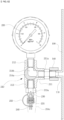
- FIG. 1 is an overall perspective view of a variable air pressure regulating device for an expansion tank according to an embodiment of the present invention
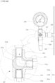
- FIG. 2 is a cross-sectional view of the variable air pressure regulating device for an expansion tank according to the embodiment of the present invention.
- the present invention is configured to mainly include an expansion tank 100, a pressure regulation unit 200, and a regulation-unit cover 300.
- the expansion tank 100 is provided with a rubber bag 120 therein and an air injection/discharge port 110 through which air is injected into or discharged from the expansion tank 100 so as to control the pressure.
- the rubber bag 120 has a fluid pipe connector 130 at an upper portion thereof to be connected to the fluid pipe P.
- air is injected into the space between the rubber bag 120 and the inner wall of the expansion tank 100 at the same pressure as that of the fluid pipe P through the air injection/discharge port 110 and then sealed.
- the fluid that is expanded due to the change of the pressure of the fluid flowing through the fluid pipe P is flowed into the rubber bag 120 by the pressure difference between the inside of the expansion tank 100 and the fluid pipe P, and thus, the pressure of the fluid pipe P is dispersed, so that it is possible to prevent the fluid pipe P from being damaged and to maintain the fluid pipe P at a constant pressure.
- a drain 150 is further provided at a lower portion of the expansion tank 100, so that a fluid is allowed to be easily discharged to the outside when the rubber bag 120 is burst or the fluid leaks.
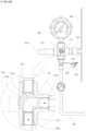
- FIG. 3 is a detailed perspective view illustrating a pressure regulation unit of the variable air pressure regulating device for an expansion tank according to the embodiment of the present invention
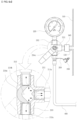
- FIG. 4 is a detailed exploded perspective view illustrating the pressure regulation unit of the variable air pressure regulating device for an expansion tank according to the embodiment of the present invention.
- the pressure regulation unit 200 is a means for regulating the pressure as the internal pressure of the expansion tank 100 is changed. Since the pressure of the air injected into the expansion tank 100 needs to be set according to a change of surrounding environments such as sizes and heights of buildings or facilities, capacity and pressure of heat source equipment, pressures of pumps connected to cooling/heating pipes and cold/hot water pipes, and pressure of a fluid pipe P connected to the expansion tank 100, it is necessary to regulate the pressure to the optimum pressure.
- the pressure regulation unit 200 is coupled to a flow path formed on a side surface of the air injection/discharge port 110 of the expansion tank 100 by a nipple 211a and a half coupling 140.
- the pressure regulation unit 200 is configured to include a three-way ball valve 210 in which three flow paths are formed and which is capable of selectively setting the flow path, a pressure gauge 220 which is coupled to an upper portion of the three-way ball valve 210 to check the internal pressure of the expansion tank 100, and a valve core 230 which is installed in a flow path other than the flow path in which the pressure gauge 220 is installed to be capable of discharging air from the expansion tank 100 or injecting air from the outside into the expansion tank 100.
- the three-way ball valve 210 is provided with flow paths extending in three directions, that is, upward, downward, and sideward.
- the upper flow path 212 is provided with a pressure gauge 220, the lower flow path 213 are coupled to the valve core 230, and the side flow path 211 is coupled to the air injection/discharge port 110 of the expansion tank 100 by the nipple 211a.
- a flow path setting member 214 which can selectively change the flow path is further provided at the center where the three flow paths meet.
- valve core 230 is connected to the lower flow path by a nipple 213a.
- the flow path setting member 214 is configured to include a valve 214a having a shape of a ball in which a flow path is formed, a variable flow path 214b in which two flow paths are formed at 90 degrees inside the valve in a penetrating manner, and a lever 214c by which the valve 214a is operated.
- the valve core 230 is a means for facilitating the injection and discharging of air.
- the valve core 230 is provided with a spring and a packing which is always pressurized outwards by the air pressure, and thus, the valve core is opened or closed by pushing a switch 231 connected to the packing.
- the air inside the expansion tank 100 can be discharged to the outside.
- an air injecting means is connected to the valve core 230, the valve core 230 is opened by pushing the switch 231 by the air injecting device 400, and air can be easily injected into the expansion tank 100 through the valve core 230.
- the valve core 230 is further provided with a protective cap 240 for preventing the valve core 230 from being opened or damaged by external factors.
- the protective cap 240 covers the bottom of the valve core 230 and is connected to the valve core 230 through a strap 250, so that a risk of loss can be minimized at the time of attaching and detaching.
- the regulation-unit cover 300 is further provided on the outer side of the pressure regulation unit 200.
- the regulation-unit cover 300 is integrally provided in the expansion tank 100. The upper portion and the two sides of the pressure regulation unit 200 are blocked by the regulation-unit cover 300, and the lower portion of the regulation-unit cover 300 is open, so that it is possible to prevent the pressure regulation unit 200 from being damaged during the equipment construction or during the using, and it is possible to easily connect the air injecting means to the lower portion at the time of air injection.
- FIG. 5 is a detailed cross-sectional view illustrating the pressure regulation unit of the variable air pressure regulating device for an expansion tank according to the embodiment of the present invention.
- valve 214a of the flow-path setting member 214 has a variable flow path 214b formed at 90 degrees and penetrating in two directions.
- variable flow path 214b is rotated by the lever 214c and is rotated together with the rotation of the lever 214c so that a required flow path can be selectively set among the three flow paths.
- variable air pressure regulating device for an expansion tank According to one embodiment of the present invention, operation states of the variable air pressure regulating device for an expansion tank according to one embodiment of the present invention will be described in detail with reference to the accompanying drawings.
- FIG. 6A is a cross-sectional view illustrating a state in which a flow path is changed only toward a pressure gauge side in the variable air pressure regulating device for an expansion tank according to the embodiment of the present invention.
- variable flow path 214b formed in the valve 214a is connected to the expansion tank 100 and the pressure gauge 220, so that the pressure of the expansion tank 100 can be immediately checked through the pressure gauge 220.
- FIG. 6B is a cross-sectional view illustrating a state in which the flow path is changed only toward the air injecting device side in the variable air pressure regulating device for an expansion tank according to the embodiment of the present invention.
- variable flow path 214b formed in the valve 214a forms a flow path only toward the expansion tank 100 and the valve core 230 side, so that it is possible to inject air directly into the expansion tank by using the air injecting device.
- This flow path is used for the case where a separate pressure gauge is provided to the air injecting device 400. Since a large amount of air can be injected while checking the internal pressure of the expansion tank 100, it is possible to regulate the air pressure of the expansion tank 100) in a short time.
- FIG. 6C is a cross-sectional view illustrating a state in which the flow path is changed to both of the air injecting device side and the pressure gauge side in the variable air pressure regulating device for an expansion tank according to one embodiment of the present invention.
- variable flow path 214b formed in the valve 214a is connected to all of the expansion tank 100, the valve core 230, and the pressure gauge 220.
- This flow path is used for the case where there is no pressure gauge in the air injecting device or the case where air is discharged. Since air needs to be injected or discharged while checking the internal air pressure of the expansion tank, the flow path is formed in the two directions to inject or discharge the air.
- the air pressure can be checked by the pressure regulation unit in maintaining the internal pressure of the expansion tank, and the air inside the expansion tank can be easily discharged or injected, so that it is possible to conveniently maintain and control the expansion tank.
- the present invention relates to a variable air pressure regulating device for an expansion tank and is applied and used for cooling/heating pipes of buildings or large-scale facilities, and thus, the present invention can be used in industries related to air conditioning equipment and cooling/heating systems of buildings.
Landscapes
- Engineering & Computer Science (AREA)
- General Engineering & Computer Science (AREA)
- Mechanical Engineering (AREA)
- Physics & Mathematics (AREA)
- Thermal Sciences (AREA)
- Chemical & Material Sciences (AREA)
- Combustion & Propulsion (AREA)
- Control Of Fluid Pressure (AREA)
Claims (3)
- Variable Luftdruckregelungsvorrichtung für ein Ausdehnungsgefäß (100), umfassendein Ausdehnungsgefäß (100), das mit einem Gummisack (120) darin, einer Lufteinblas-/-auslassöffnung (110) an einer Außenseite davon und einem Abfluss (150) an einem Boden davon versehen ist, wobei der Abfluss (150) in der Lage ist, Wasser auszulassen, das austritt, wenn der Gummisack (120) geplatzt ist; undeine Druckregelungseinheit (200), die in der Lage ist, einen Innendruck des Ausdehnungsgefäßes (100) zu regeln; dadurch gekennzeichnet, dass die Druckregelungseinheit (200) mit dem Lufteinblas-/-auslassanschluss (110) verbunden ist und aufweist:einen Dreiwege-Kugelhahn (210), der mit einem oberen Strömungsweg (212), einem unteren Strömungsweg (213) und einem seitlichen Strömungsweg (211) versehen ist, die in drei Richtungen nach oben, nach unten und zur Seite gebildet sind, und der mit einem Strömungsweg-Einstellelement (214) versehen ist, das in der Lage ist, selektiv einen Strömungsweg in einer Mitte einzustellen, in der sich die drei Strömungswege treffen;einen Druckmesser (220), der in dem oberen Strömungsweg (212) des Dreiwege-Kugelhahns (210) installiert ist, um den Innendruck des Ausdehnungsgefäßes (100) zu überprüfen; undeinen Ventileinsatz (230), der in dem unteren Strömungsweg (213) des Dreiwege-Kugelhahns (210) installiert ist, um in der Lage zu sein, Luft in das Ausdehnungsgefäß (100) einzublasen oder aus diesem auszulassen,wobeider seitliche Strömungsweg (211) mit der Lufteinblas-/- auslassöffnung (110) gekoppelt ist; unddas Strömungsweg-Einstellelement (214) aufweist: ein Ventil (214a) mit einer Form einer Kugel; einen variablen Strömungsweg (214b), bei dem zwei Strömungswege in dem Ventil (214a) in einem Winkel von 90 Grad in einer durchdringenden Weise gebildet sind; und einen Hebel (214c), durch den das Ventil (214a) betätigt werden kann, wobei das Einstellelement (214) derart eingerichtet ist, dass, wenn der Hebel (214c) vertikal nach unten betätigt wird, der variable Strömungsweg (214b) einen Strömungsweg in Richtung des Ausdehnungsgefäßes (100) und des Druckmessers (220) bildet, so dass der Druck des Ausdehnungsgefäßes (100) über den Druckmesser (220) überprüft werden kann, und, wenn der Hebel (214c) um 90 Grad nach links betätigt wird, der variable Strömungsweg (214b) einen Strömungsweg in Richtung des Ausdehnungsgefäßes (100) und des Ventileinsatzes (230) bildet, so dass Luft in das Ausdehnungsgefäß (100) eingeblasen werden kann, und, wenn der Hebel (214c) in eine Richtung von 45 Grad betätigt wird, der Strömungsweg so eingestellt wird, dass der variable Strömungsweg (214b) das gesamte Ausdehnungsgefäß (100), den Ventileinsatz (230) und den Druckmesser (220) verbindet.
- Variable Luftdruckregelungsvorrichtung nach Anspruch 1, wobei außerhalb des Ventileinsatzes (230) eine Schutzkappe (240) zum Schützen des Ventileinsatzes (230) und ein Band (250), das zwischen der Schutzkappe (240) und dem Ventileinsatz (230) angeordnet ist, zum Verbinden und Tragen der Schutzkappe (240) vorgesehen sind.
- Variable Luftdruckregelungsvorrichtung nach Anspruch 1, ferner umfassend eine Regelungseinheit-Abdeckung (300), die mit dem Ausdehnungsgefäß (100) gekoppelt ist, um zu verhindern, dass die Druckregelungseinheit (200) beschädigt wird.
Applications Claiming Priority (2)
| Application Number | Priority Date | Filing Date | Title |
|---|---|---|---|
| KR2020160007592U KR200483915Y1 (ko) | 2016-12-28 | 2016-12-28 | 팽창탱크용 가변식 공기압 조절 장치 |
| PCT/KR2017/013077 WO2018124470A1 (ko) | 2016-12-28 | 2017-11-17 | 팽창탱크용 가변식 공기압 조절 장치 |
Publications (3)
| Publication Number | Publication Date |
|---|---|
| EP3564590A1 EP3564590A1 (de) | 2019-11-06 |
| EP3564590A4 EP3564590A4 (de) | 2020-09-02 |
| EP3564590B1 true EP3564590B1 (de) | 2024-04-10 |
Family
ID=59315912
Family Applications (1)
| Application Number | Title | Priority Date | Filing Date |
|---|---|---|---|
| EP17888787.3A Active EP3564590B1 (de) | 2016-12-28 | 2017-11-17 | Luftdruckregler des variablen typs für einen expansionstank |
Country Status (4)
| Country | Link |
|---|---|
| US (1) | US10955144B2 (de) |
| EP (1) | EP3564590B1 (de) |
| KR (1) | KR200483915Y1 (de) |
| WO (1) | WO2018124470A1 (de) |
Families Citing this family (3)
| Publication number | Priority date | Publication date | Assignee | Title |
|---|---|---|---|---|
| TWI771993B (zh) * | 2021-04-22 | 2022-07-21 | 唐國忠 | 多層伸縮氣囊擠壓空氣桶 |
| CN113790163A (zh) * | 2021-09-30 | 2021-12-14 | 珠海格力电器股份有限公司 | 膨胀水泵系统及包含其的闭式水系统和空调设备 |
| CN114198947A (zh) * | 2022-01-10 | 2022-03-18 | 厦门三和盛科技有限公司 | 一种用于制冷回路的集成水箱及设备 |
Citations (1)
| Publication number | Priority date | Publication date | Assignee | Title |
|---|---|---|---|---|
| DE19812272A1 (de) * | 1998-03-09 | 1999-10-21 | Lovato Gmbh | Sicherheitsanschlußstück zum Anschließen eines Ausdehnungsgefäßes an einen geschlossenen Fluidkreislauf |
Family Cites Families (48)
| Publication number | Priority date | Publication date | Assignee | Title |
|---|---|---|---|---|
| US447100A (en) * | 1891-02-24 | William c | ||
| US473722A (en) * | 1892-04-26 | William c | ||
| US1904697A (en) * | 1929-05-21 | 1933-04-18 | Edward H Ruppert | Safety draw-off apparatus for hot water systems |
| US2166235A (en) * | 1937-05-29 | 1939-07-18 | American Radiator & Standard | Expansion tank |
| US2790606A (en) * | 1953-09-04 | 1957-04-30 | Warren Webster & Co | Method for expelling air from a closed hot water system |
| FR1510907A (fr) * | 1966-11-10 | 1968-01-26 | Sud Aviation | Bâche hydraulique à soufflet de grande capacité |
| US3628573A (en) * | 1970-07-21 | 1971-12-21 | Alpura Ag | Diaphragm chamber-damping device for damping fluid shocks in pipe systems |
| EP0016316A1 (de) * | 1979-03-19 | 1980-10-01 | Winkelmann & Pannhoff GmbH | Kompressorgesteuertes Ausdehnungsgefäss |
| AT371236B (de) * | 1980-09-05 | 1983-06-10 | Eder Anton | Druckausgleichsvorrichtung fuer heizanlagen |
| GB2176589A (en) * | 1985-06-01 | 1986-12-31 | Warmac Ltd | Expansion tank |
| CN85104763B (zh) | 1985-06-13 | 1988-08-24 | 沈汉石 | 液压系统中消除气穴的方法和装置 |
| NL8502736A (nl) * | 1985-10-07 | 1987-05-04 | Flamco Bv | Expansievat met blaasvormig membraan. |
| DE3613906A1 (de) * | 1986-04-24 | 1987-10-29 | Michael Dipl Ing Senger | Vorrichtung zur inhaltsueberwachung von mit gasdruck beaufschlagten ausdehnungsgefaessen und dgl. |
| US5218995A (en) * | 1992-08-06 | 1993-06-15 | Lee Shih Ping | Three-way valve assembly with water quantity recording meter for a storage tank of the reverse osmosis water purifier |
| GB9300967D0 (en) * | 1993-01-19 | 1993-03-10 | Hanson Granville George | Improvements in or relating to hot water containers |
| DE4320333C2 (de) * | 1993-06-21 | 2002-11-14 | Jens Pannenborg | Verfahren und Vorrichtung zur Sicherung der Systemdrücke in einem geschlossenen Wasserkreislauf |
| DE19610598A1 (de) * | 1996-03-18 | 1997-09-25 | Dieter Plobst | Anordnung zum Ausgleich von Volumenschwankungen von Flüssigkeitssystem in Anlagen |
| DE19813970A1 (de) * | 1998-03-20 | 1999-09-30 | Otto Heat Heizungs | Kombiniertes Brauch- und Heizungswasserausdehnungsgefäß |
| US6089837A (en) * | 1999-06-18 | 2000-07-18 | Blacoh Fluid Control, Inc. | Pump inlet stabilizer with a control unit for creating a positive pressure and a partial vacuum |
| GB9920213D0 (en) * | 1999-08-27 | 1999-10-27 | Binks Ltd | Pressure regulation apparatus |
| DE19945105A1 (de) * | 1999-09-21 | 2001-03-29 | Otto Heat Heizungs-, Energie- Und Anlagentechnik Gmbh & Co. Kg | Druckbehälter für Versorgungsanlagen |
| DE19959941C2 (de) * | 1999-12-13 | 2002-08-29 | Gutjahr Gmbh | Druckausdehnungsvorrichtung |
| US6401966B2 (en) * | 2000-05-23 | 2002-06-11 | Fu Chung Tsai | Plastic pressure vessel structure |
| KR100489554B1 (ko) | 2002-09-25 | 2005-05-17 | 김성철 | 맥동 감소장치 |
| US7322488B2 (en) * | 2003-07-22 | 2008-01-29 | Flexcon Industries Trust | Expansion tank with double diaphragm |
| US7303091B2 (en) * | 2003-07-22 | 2007-12-04 | Flexcon Industries | Expansion tank with double diaphragm |
| EP1799558A4 (de) * | 2004-10-12 | 2012-05-02 | Flexcon Ind | Expansionstank mit doppelmembran |
| US20070186873A1 (en) * | 2006-02-13 | 2007-08-16 | Nikolay Polkhouskiy | Pressure control isolation and flood preventative tank for a hot water based heating system |
| US7775260B2 (en) * | 2006-08-08 | 2010-08-17 | James Fuller | Expansion tank with alarm system |
| US8633825B2 (en) * | 2006-08-08 | 2014-01-21 | Wessels Company | Expansion tank with a predictive sensor |
| US20080035647A1 (en) * | 2006-08-08 | 2008-02-14 | James Fuller | Expansion tank with a predictive sensor |
| US7472720B2 (en) * | 2006-10-30 | 2009-01-06 | Young Engineering & Manufacturing, Inc. | High flow nozzle system for flow control in bladder surge tanks |
| US20100000920A1 (en) * | 2008-07-07 | 2010-01-07 | Ermanno Martinello | Membrane coating for a water pressurization Bladder |
| US8375991B2 (en) * | 2009-01-26 | 2013-02-19 | Watts Regulator Company | Valve assembly |
| CH702905A1 (de) * | 2010-03-26 | 2011-09-30 | Olaer Schweiz Ag | Druckausgleichsvorrichtung für flüssigkeitsdurchströmte Systeme. |
| KR200462979Y1 (ko) * | 2010-08-27 | 2012-10-11 | 양재구 | 누수 감지 기능을 구비한 격막식 팽창탱크 |
| TWI397490B (zh) * | 2010-12-16 | 2013-06-01 | Pa E Machinery Ind Co Ltd | Pressure tank with protective unit |
| CA2800431A1 (en) * | 2012-01-05 | 2013-07-05 | 2440644 Canada Inc. | Expansion tank with membrane thermal protection |
| JP6242046B2 (ja) * | 2012-01-11 | 2017-12-06 | 株式会社キッツ | アクチュエータ付き回転弁 |
| US9146137B2 (en) * | 2012-12-12 | 2015-09-29 | Amtrol Licensing Inc. | Air cell indicator |
| KR101462071B1 (ko) * | 2013-06-13 | 2014-11-14 | (주)조영엔지니어링 | 플로우 가이드 기능을 겸비한 팽창 탱크의 블래더 터짐 방지 구조 |
| US9982825B2 (en) * | 2013-12-16 | 2018-05-29 | Young Engineering & Manufacturing, Inc. | Bladder surge suppressor |
| US9915433B2 (en) * | 2014-05-30 | 2018-03-13 | Amtrol Licensing Inc. | Moisture detecting air cap indicator for expansion tank failure |
| ITUB20150975A1 (it) * | 2015-05-28 | 2016-11-28 | Zilmet S P A | Vaso di espansione con raccordo migliorato |
| CA2988790C (en) * | 2015-06-18 | 2023-07-04 | Les Solutions Calefactio Inc. | Multi-function pressure vessel |
| US10054266B2 (en) * | 2016-03-09 | 2018-08-21 | Amtrol Licensing Inc. | Pressure vessel with dome supported diaphragm |
| WO2017173144A1 (en) * | 2016-03-31 | 2017-10-05 | Flexcon Industries, Inc. | Expansion tank with improved single diaphragm |
| US20190145631A1 (en) * | 2016-05-06 | 2019-05-16 | Flexcon Industries, Inc. | Water storage tank with passive enhanced thermal energy management and resistance |
-
2016
- 2016-12-28 KR KR2020160007592U patent/KR200483915Y1/ko active Active
-
2017
- 2017-11-17 WO PCT/KR2017/013077 patent/WO2018124470A1/ko not_active Ceased
- 2017-11-17 EP EP17888787.3A patent/EP3564590B1/de active Active
- 2017-11-17 US US16/081,675 patent/US10955144B2/en active Active
Patent Citations (1)
| Publication number | Priority date | Publication date | Assignee | Title |
|---|---|---|---|---|
| DE19812272A1 (de) * | 1998-03-09 | 1999-10-21 | Lovato Gmbh | Sicherheitsanschlußstück zum Anschließen eines Ausdehnungsgefäßes an einen geschlossenen Fluidkreislauf |
Also Published As
| Publication number | Publication date |
|---|---|
| EP3564590A4 (de) | 2020-09-02 |
| KR200483915Y1 (ko) | 2017-07-11 |
| US20200173666A1 (en) | 2020-06-04 |
| EP3564590A1 (de) | 2019-11-06 |
| WO2018124470A1 (ko) | 2018-07-05 |
| US10955144B2 (en) | 2021-03-23 |
Similar Documents
| Publication | Publication Date | Title |
|---|---|---|
| US9212751B2 (en) | Valve system and method | |
| EP3564590B1 (de) | Luftdruckregler des variablen typs für einen expansionstank | |
| EP3295067B1 (de) | Kugelventil mit druckentlastungsfunktion | |
| CA2980682A1 (en) | Multiway valve with bypass circuit | |
| JP2014185638A (ja) | 選択可能な排出口を有するポンプ | |
| US20130180993A1 (en) | Expansion tank with membrane thermal protection | |
| JPH06100369B2 (ja) | 流体装置 | |
| KR20200032810A (ko) | 온도식 자동밸브를 구비한 동파방지 모듈 및 이를 이용한 수도꼭지 시스템 | |
| US12007124B2 (en) | Distribution pump arrangement for a hydraulic distribution system having changing flowing direction | |
| BR112012027663B1 (pt) | válvula de alívio de pressão multimodo | |
| US20120228308A1 (en) | Pressure Vessel | |
| BRPI0519151B1 (pt) | Corpo de válvula | |
| KR101770787B1 (ko) | 양방향 스프링 개폐밸브 | |
| CN105765280A (zh) | 用于调节环路中液体的系统 | |
| US20140265143A1 (en) | Mechanical seal support system | |
| US20070186873A1 (en) | Pressure control isolation and flood preventative tank for a hot water based heating system | |
| CN108589832A (zh) | 应用于供水管路的限压阀 | |
| CN108937441B (zh) | 一种水壶及具有其的冰箱 | |
| CN209959896U (zh) | 阀门密封状态的密封监测系统 | |
| GB2549301A (en) | Apparatus for controlling the flow of fluid through a conduit | |
| JP3883536B2 (ja) | 膨張タンク | |
| CN223740592U (zh) | 一种泄压阀控制装置 | |
| JP2015172403A (ja) | 流路切替弁及びそれを備えた給湯装置 | |
| RU2482367C1 (ru) | Обратный клапан | |
| CN107725832B (zh) | 一种风机盘管温控阀组 |
Legal Events
| Date | Code | Title | Description |
|---|---|---|---|
| STAA | Information on the status of an ep patent application or granted ep patent |
Free format text: STATUS: THE INTERNATIONAL PUBLICATION HAS BEEN MADE |
|
| PUAI | Public reference made under article 153(3) epc to a published international application that has entered the european phase |
Free format text: ORIGINAL CODE: 0009012 |
|
| STAA | Information on the status of an ep patent application or granted ep patent |
Free format text: STATUS: REQUEST FOR EXAMINATION WAS MADE |
|
| 17P | Request for examination filed |
Effective date: 20190729 |
|
| AK | Designated contracting states |
Kind code of ref document: A1 Designated state(s): AL AT BE BG CH CY CZ DE DK EE ES FI FR GB GR HR HU IE IS IT LI LT LU LV MC MK MT NL NO PL PT RO RS SE SI SK SM TR |
|
| AX | Request for extension of the european patent |
Extension state: BA ME |
|
| DAV | Request for validation of the european patent (deleted) | ||
| DAX | Request for extension of the european patent (deleted) | ||
| A4 | Supplementary search report drawn up and despatched |
Effective date: 20200805 |
|
| RIC1 | Information provided on ipc code assigned before grant |
Ipc: F24D 19/08 20060101ALI20200730BHEP Ipc: F16K 11/00 20060101ALI20200730BHEP Ipc: F24D 3/10 20060101AFI20200730BHEP Ipc: F24D 19/10 20060101ALI20200730BHEP |
|
| GRAP | Despatch of communication of intention to grant a patent |
Free format text: ORIGINAL CODE: EPIDOSNIGR1 |
|
| STAA | Information on the status of an ep patent application or granted ep patent |
Free format text: STATUS: GRANT OF PATENT IS INTENDED |
|
| INTG | Intention to grant announced |
Effective date: 20231219 |
|
| GRAS | Grant fee paid |
Free format text: ORIGINAL CODE: EPIDOSNIGR3 |
|
| GRAA | (expected) grant |
Free format text: ORIGINAL CODE: 0009210 |
|
| STAA | Information on the status of an ep patent application or granted ep patent |
Free format text: STATUS: THE PATENT HAS BEEN GRANTED |
|
| AK | Designated contracting states |
Kind code of ref document: B1 Designated state(s): AL AT BE BG CH CY CZ DE DK EE ES FI FR GB GR HR HU IE IS IT LI LT LU LV MC MK MT NL NO PL PT RO RS SE SI SK SM TR |
|
| REG | Reference to a national code |
Ref country code: GB Ref legal event code: FG4D |
|
| REG | Reference to a national code |
Ref country code: CH Ref legal event code: EP |
|
| REG | Reference to a national code |
Ref country code: DE Ref legal event code: R096 Ref document number: 602017080970 Country of ref document: DE |
|
| REG | Reference to a national code |
Ref country code: IE Ref legal event code: FG4D |
|
| REG | Reference to a national code |
Ref country code: LT Ref legal event code: MG9D |
|
| REG | Reference to a national code |
Ref country code: NL Ref legal event code: MP Effective date: 20240410 |
|
| REG | Reference to a national code |
Ref country code: AT Ref legal event code: MK05 Ref document number: 1675252 Country of ref document: AT Kind code of ref document: T Effective date: 20240410 |
|
| PG25 | Lapsed in a contracting state [announced via postgrant information from national office to epo] |
Ref country code: NL Free format text: LAPSE BECAUSE OF FAILURE TO SUBMIT A TRANSLATION OF THE DESCRIPTION OR TO PAY THE FEE WITHIN THE PRESCRIBED TIME-LIMIT Effective date: 20240410 |
|
| PG25 | Lapsed in a contracting state [announced via postgrant information from national office to epo] |
Ref country code: NL Free format text: LAPSE BECAUSE OF FAILURE TO SUBMIT A TRANSLATION OF THE DESCRIPTION OR TO PAY THE FEE WITHIN THE PRESCRIBED TIME-LIMIT Effective date: 20240410 |
|
| PG25 | Lapsed in a contracting state [announced via postgrant information from national office to epo] |
Ref country code: IS Free format text: LAPSE BECAUSE OF FAILURE TO SUBMIT A TRANSLATION OF THE DESCRIPTION OR TO PAY THE FEE WITHIN THE PRESCRIBED TIME-LIMIT Effective date: 20240810 |
|
| PG25 | Lapsed in a contracting state [announced via postgrant information from national office to epo] |
Ref country code: BG Free format text: LAPSE BECAUSE OF FAILURE TO SUBMIT A TRANSLATION OF THE DESCRIPTION OR TO PAY THE FEE WITHIN THE PRESCRIBED TIME-LIMIT Effective date: 20240410 |
|
| PG25 | Lapsed in a contracting state [announced via postgrant information from national office to epo] |
Ref country code: HR Free format text: LAPSE BECAUSE OF FAILURE TO SUBMIT A TRANSLATION OF THE DESCRIPTION OR TO PAY THE FEE WITHIN THE PRESCRIBED TIME-LIMIT Effective date: 20240410 Ref country code: FI Free format text: LAPSE BECAUSE OF FAILURE TO SUBMIT A TRANSLATION OF THE DESCRIPTION OR TO PAY THE FEE WITHIN THE PRESCRIBED TIME-LIMIT Effective date: 20240410 |
|
| PG25 | Lapsed in a contracting state [announced via postgrant information from national office to epo] |
Ref country code: GR Free format text: LAPSE BECAUSE OF FAILURE TO SUBMIT A TRANSLATION OF THE DESCRIPTION OR TO PAY THE FEE WITHIN THE PRESCRIBED TIME-LIMIT Effective date: 20240711 |
|
| PG25 | Lapsed in a contracting state [announced via postgrant information from national office to epo] |
Ref country code: PT Free format text: LAPSE BECAUSE OF FAILURE TO SUBMIT A TRANSLATION OF THE DESCRIPTION OR TO PAY THE FEE WITHIN THE PRESCRIBED TIME-LIMIT Effective date: 20240812 |
|
| PG25 | Lapsed in a contracting state [announced via postgrant information from national office to epo] |
Ref country code: ES Free format text: LAPSE BECAUSE OF FAILURE TO SUBMIT A TRANSLATION OF THE DESCRIPTION OR TO PAY THE FEE WITHIN THE PRESCRIBED TIME-LIMIT Effective date: 20240410 |
|
| PG25 | Lapsed in a contracting state [announced via postgrant information from national office to epo] |
Ref country code: AT Free format text: LAPSE BECAUSE OF FAILURE TO SUBMIT A TRANSLATION OF THE DESCRIPTION OR TO PAY THE FEE WITHIN THE PRESCRIBED TIME-LIMIT Effective date: 20240410 |
|
| PG25 | Lapsed in a contracting state [announced via postgrant information from national office to epo] |
Ref country code: PL Free format text: LAPSE BECAUSE OF FAILURE TO SUBMIT A TRANSLATION OF THE DESCRIPTION OR TO PAY THE FEE WITHIN THE PRESCRIBED TIME-LIMIT Effective date: 20240410 |
|
| PG25 | Lapsed in a contracting state [announced via postgrant information from national office to epo] |
Ref country code: LV Free format text: LAPSE BECAUSE OF FAILURE TO SUBMIT A TRANSLATION OF THE DESCRIPTION OR TO PAY THE FEE WITHIN THE PRESCRIBED TIME-LIMIT Effective date: 20240410 |
|
| PG25 | Lapsed in a contracting state [announced via postgrant information from national office to epo] |
Ref country code: PT Free format text: LAPSE BECAUSE OF FAILURE TO SUBMIT A TRANSLATION OF THE DESCRIPTION OR TO PAY THE FEE WITHIN THE PRESCRIBED TIME-LIMIT Effective date: 20240812 Ref country code: PL Free format text: LAPSE BECAUSE OF FAILURE TO SUBMIT A TRANSLATION OF THE DESCRIPTION OR TO PAY THE FEE WITHIN THE PRESCRIBED TIME-LIMIT Effective date: 20240410 Ref country code: NO Free format text: LAPSE BECAUSE OF FAILURE TO SUBMIT A TRANSLATION OF THE DESCRIPTION OR TO PAY THE FEE WITHIN THE PRESCRIBED TIME-LIMIT Effective date: 20240710 Ref country code: LV Free format text: LAPSE BECAUSE OF FAILURE TO SUBMIT A TRANSLATION OF THE DESCRIPTION OR TO PAY THE FEE WITHIN THE PRESCRIBED TIME-LIMIT Effective date: 20240410 Ref country code: IS Free format text: LAPSE BECAUSE OF FAILURE TO SUBMIT A TRANSLATION OF THE DESCRIPTION OR TO PAY THE FEE WITHIN THE PRESCRIBED TIME-LIMIT Effective date: 20240810 Ref country code: HR Free format text: LAPSE BECAUSE OF FAILURE TO SUBMIT A TRANSLATION OF THE DESCRIPTION OR TO PAY THE FEE WITHIN THE PRESCRIBED TIME-LIMIT Effective date: 20240410 Ref country code: GR Free format text: LAPSE BECAUSE OF FAILURE TO SUBMIT A TRANSLATION OF THE DESCRIPTION OR TO PAY THE FEE WITHIN THE PRESCRIBED TIME-LIMIT Effective date: 20240711 Ref country code: FI Free format text: LAPSE BECAUSE OF FAILURE TO SUBMIT A TRANSLATION OF THE DESCRIPTION OR TO PAY THE FEE WITHIN THE PRESCRIBED TIME-LIMIT Effective date: 20240410 Ref country code: ES Free format text: LAPSE BECAUSE OF FAILURE TO SUBMIT A TRANSLATION OF THE DESCRIPTION OR TO PAY THE FEE WITHIN THE PRESCRIBED TIME-LIMIT Effective date: 20240410 Ref country code: BG Free format text: LAPSE BECAUSE OF FAILURE TO SUBMIT A TRANSLATION OF THE DESCRIPTION OR TO PAY THE FEE WITHIN THE PRESCRIBED TIME-LIMIT Effective date: 20240410 Ref country code: AT Free format text: LAPSE BECAUSE OF FAILURE TO SUBMIT A TRANSLATION OF THE DESCRIPTION OR TO PAY THE FEE WITHIN THE PRESCRIBED TIME-LIMIT Effective date: 20240410 Ref country code: RS Free format text: LAPSE BECAUSE OF FAILURE TO SUBMIT A TRANSLATION OF THE DESCRIPTION OR TO PAY THE FEE WITHIN THE PRESCRIBED TIME-LIMIT Effective date: 20240710 |
|
| REG | Reference to a national code |
Ref country code: DE Ref legal event code: R097 Ref document number: 602017080970 Country of ref document: DE |
|
| PG25 | Lapsed in a contracting state [announced via postgrant information from national office to epo] |
Ref country code: DK Free format text: LAPSE BECAUSE OF FAILURE TO SUBMIT A TRANSLATION OF THE DESCRIPTION OR TO PAY THE FEE WITHIN THE PRESCRIBED TIME-LIMIT Effective date: 20240410 |
|
| PG25 | Lapsed in a contracting state [announced via postgrant information from national office to epo] |
Ref country code: EE Free format text: LAPSE BECAUSE OF FAILURE TO SUBMIT A TRANSLATION OF THE DESCRIPTION OR TO PAY THE FEE WITHIN THE PRESCRIBED TIME-LIMIT Effective date: 20240410 |
|
| PG25 | Lapsed in a contracting state [announced via postgrant information from national office to epo] |
Ref country code: CZ Free format text: LAPSE BECAUSE OF FAILURE TO SUBMIT A TRANSLATION OF THE DESCRIPTION OR TO PAY THE FEE WITHIN THE PRESCRIBED TIME-LIMIT Effective date: 20240410 |
|
| PG25 | Lapsed in a contracting state [announced via postgrant information from national office to epo] |
Ref country code: RO Free format text: LAPSE BECAUSE OF FAILURE TO SUBMIT A TRANSLATION OF THE DESCRIPTION OR TO PAY THE FEE WITHIN THE PRESCRIBED TIME-LIMIT Effective date: 20240410 Ref country code: SK Free format text: LAPSE BECAUSE OF FAILURE TO SUBMIT A TRANSLATION OF THE DESCRIPTION OR TO PAY THE FEE WITHIN THE PRESCRIBED TIME-LIMIT Effective date: 20240410 |
|
| PG25 | Lapsed in a contracting state [announced via postgrant information from national office to epo] |
Ref country code: SM Free format text: LAPSE BECAUSE OF FAILURE TO SUBMIT A TRANSLATION OF THE DESCRIPTION OR TO PAY THE FEE WITHIN THE PRESCRIBED TIME-LIMIT Effective date: 20240410 |
|
| PG25 | Lapsed in a contracting state [announced via postgrant information from national office to epo] |
Ref country code: SM Free format text: LAPSE BECAUSE OF FAILURE TO SUBMIT A TRANSLATION OF THE DESCRIPTION OR TO PAY THE FEE WITHIN THE PRESCRIBED TIME-LIMIT Effective date: 20240410 Ref country code: SK Free format text: LAPSE BECAUSE OF FAILURE TO SUBMIT A TRANSLATION OF THE DESCRIPTION OR TO PAY THE FEE WITHIN THE PRESCRIBED TIME-LIMIT Effective date: 20240410 Ref country code: RO Free format text: LAPSE BECAUSE OF FAILURE TO SUBMIT A TRANSLATION OF THE DESCRIPTION OR TO PAY THE FEE WITHIN THE PRESCRIBED TIME-LIMIT Effective date: 20240410 Ref country code: EE Free format text: LAPSE BECAUSE OF FAILURE TO SUBMIT A TRANSLATION OF THE DESCRIPTION OR TO PAY THE FEE WITHIN THE PRESCRIBED TIME-LIMIT Effective date: 20240410 Ref country code: DK Free format text: LAPSE BECAUSE OF FAILURE TO SUBMIT A TRANSLATION OF THE DESCRIPTION OR TO PAY THE FEE WITHIN THE PRESCRIBED TIME-LIMIT Effective date: 20240410 Ref country code: CZ Free format text: LAPSE BECAUSE OF FAILURE TO SUBMIT A TRANSLATION OF THE DESCRIPTION OR TO PAY THE FEE WITHIN THE PRESCRIBED TIME-LIMIT Effective date: 20240410 |
|
| PLBE | No opposition filed within time limit |
Free format text: ORIGINAL CODE: 0009261 |
|
| STAA | Information on the status of an ep patent application or granted ep patent |
Free format text: STATUS: NO OPPOSITION FILED WITHIN TIME LIMIT |
|
| 26N | No opposition filed |
Effective date: 20250113 |
|
| PG25 | Lapsed in a contracting state [announced via postgrant information from national office to epo] |
Ref country code: SI Free format text: LAPSE BECAUSE OF FAILURE TO SUBMIT A TRANSLATION OF THE DESCRIPTION OR TO PAY THE FEE WITHIN THE PRESCRIBED TIME-LIMIT Effective date: 20240410 |
|
| REG | Reference to a national code |
Ref country code: DE Ref legal event code: R119 Ref document number: 602017080970 Country of ref document: DE |
|
| REG | Reference to a national code |
Ref country code: CH Ref legal event code: PL |
|
| PG25 | Lapsed in a contracting state [announced via postgrant information from national office to epo] |
Ref country code: MC Free format text: LAPSE BECAUSE OF FAILURE TO SUBMIT A TRANSLATION OF THE DESCRIPTION OR TO PAY THE FEE WITHIN THE PRESCRIBED TIME-LIMIT Effective date: 20240410 |
|
| PG25 | Lapsed in a contracting state [announced via postgrant information from national office to epo] |
Ref country code: LU Free format text: LAPSE BECAUSE OF NON-PAYMENT OF DUE FEES Effective date: 20241117 |
|
| REG | Reference to a national code |
Ref country code: CH Ref legal event code: PL |
|
| GBPC | Gb: european patent ceased through non-payment of renewal fee |
Effective date: 20241117 |
|
| PG25 | Lapsed in a contracting state [announced via postgrant information from national office to epo] |
Ref country code: CH Free format text: LAPSE BECAUSE OF NON-PAYMENT OF DUE FEES Effective date: 20241130 |
|
| REG | Reference to a national code |
Ref country code: BE Ref legal event code: MM Effective date: 20241130 |
|
| PG25 | Lapsed in a contracting state [announced via postgrant information from national office to epo] |
Ref country code: SE Free format text: LAPSE BECAUSE OF FAILURE TO SUBMIT A TRANSLATION OF THE DESCRIPTION OR TO PAY THE FEE WITHIN THE PRESCRIBED TIME-LIMIT Effective date: 20240410 |
|
| PG25 | Lapsed in a contracting state [announced via postgrant information from national office to epo] |
Ref country code: DE Free format text: LAPSE BECAUSE OF NON-PAYMENT OF DUE FEES Effective date: 20250603 |
|
| PG25 | Lapsed in a contracting state [announced via postgrant information from national office to epo] |
Ref country code: GB Free format text: LAPSE BECAUSE OF NON-PAYMENT OF DUE FEES Effective date: 20241117 Ref country code: BE Free format text: LAPSE BECAUSE OF NON-PAYMENT OF DUE FEES Effective date: 20241130 |
|
| PG25 | Lapsed in a contracting state [announced via postgrant information from national office to epo] |
Ref country code: FR Free format text: LAPSE BECAUSE OF NON-PAYMENT OF DUE FEES Effective date: 20241130 |
|
| PG25 | Lapsed in a contracting state [announced via postgrant information from national office to epo] |
Ref country code: IE Free format text: LAPSE BECAUSE OF NON-PAYMENT OF DUE FEES Effective date: 20241117 |
|
| PGFP | Annual fee paid to national office [announced via postgrant information from national office to epo] |
Ref country code: IT Payment date: 20251125 Year of fee payment: 9 |
|
| PG25 | Lapsed in a contracting state [announced via postgrant information from national office to epo] |
Ref country code: HU Free format text: LAPSE BECAUSE OF FAILURE TO SUBMIT A TRANSLATION OF THE DESCRIPTION OR TO PAY THE FEE WITHIN THE PRESCRIBED TIME-LIMIT; INVALID AB INITIO Effective date: 20171117 |