EP3564480B1 - Verfahren zum entfernen von beschichtungen von einer lüfterschaufel aus aluminiumlegierung - Google Patents
Verfahren zum entfernen von beschichtungen von einer lüfterschaufel aus aluminiumlegierung Download PDFInfo
- Publication number
- EP3564480B1 EP3564480B1 EP19171907.9A EP19171907A EP3564480B1 EP 3564480 B1 EP3564480 B1 EP 3564480B1 EP 19171907 A EP19171907 A EP 19171907A EP 3564480 B1 EP3564480 B1 EP 3564480B1
- Authority
- EP
- European Patent Office
- Prior art keywords
- blade
- nozzle
- coating
- substrate
- fan blade
- Prior art date
- Legal status (The legal status is an assumption and is not a legal conclusion. Google has not performed a legal analysis and makes no representation as to the accuracy of the status listed.)
- Active
Links
Images




Classifications
-
- B—PERFORMING OPERATIONS; TRANSPORTING
- B05—SPRAYING OR ATOMISING IN GENERAL; APPLYING FLUENT MATERIALS TO SURFACES, IN GENERAL
- B05D—PROCESSES FOR APPLYING FLUENT MATERIALS TO SURFACES, IN GENERAL
- B05D5/00—Processes for applying liquids or other fluent materials to surfaces to obtain special surface effects, finishes or structures
- B05D5/005—Repairing damaged coatings
-
- F—MECHANICAL ENGINEERING; LIGHTING; HEATING; WEAPONS; BLASTING
- F01—MACHINES OR ENGINES IN GENERAL; ENGINE PLANTS IN GENERAL; STEAM ENGINES
- F01D—NON-POSITIVE DISPLACEMENT MACHINES OR ENGINES, e.g. STEAM TURBINES
- F01D5/00—Blades; Blade-carrying members; Heating, heat-insulating, cooling or antivibration means on the blades or the members
- F01D5/12—Blades
- F01D5/28—Selecting particular materials; Particular measures relating thereto; Measures against erosion or corrosion
- F01D5/288—Protective coatings for blades
-
- B—PERFORMING OPERATIONS; TRANSPORTING
- B08—CLEANING
- B08B—CLEANING IN GENERAL; PREVENTION OF FOULING IN GENERAL
- B08B3/00—Cleaning by methods involving the use or presence of liquid or steam
- B08B3/02—Cleaning by the force of jets or sprays
- B08B3/022—Cleaning travelling work
-
- B—PERFORMING OPERATIONS; TRANSPORTING
- B08—CLEANING
- B08B—CLEANING IN GENERAL; PREVENTION OF FOULING IN GENERAL
- B08B3/00—Cleaning by methods involving the use or presence of liquid or steam
- B08B3/02—Cleaning by the force of jets or sprays
- B08B3/024—Cleaning by means of spray elements moving over the surface to be cleaned
-
- B—PERFORMING OPERATIONS; TRANSPORTING
- B08—CLEANING
- B08B—CLEANING IN GENERAL; PREVENTION OF FOULING IN GENERAL
- B08B7/00—Cleaning by methods not provided for in a single other subclass or a single group in this subclass
- B08B7/0064—Cleaning by methods not provided for in a single other subclass or a single group in this subclass by temperature changes
- B08B7/0092—Cleaning by methods not provided for in a single other subclass or a single group in this subclass by temperature changes by cooling
-
- F—MECHANICAL ENGINEERING; LIGHTING; HEATING; WEAPONS; BLASTING
- F01—MACHINES OR ENGINES IN GENERAL; ENGINE PLANTS IN GENERAL; STEAM ENGINES
- F01D—NON-POSITIVE DISPLACEMENT MACHINES OR ENGINES, e.g. STEAM TURBINES
- F01D5/00—Blades; Blade-carrying members; Heating, heat-insulating, cooling or antivibration means on the blades or the members
- F01D5/005—Repairing methods or devices
-
- F—MECHANICAL ENGINEERING; LIGHTING; HEATING; WEAPONS; BLASTING
- F01—MACHINES OR ENGINES IN GENERAL; ENGINE PLANTS IN GENERAL; STEAM ENGINES
- F01D—NON-POSITIVE DISPLACEMENT MACHINES OR ENGINES, e.g. STEAM TURBINES
- F01D5/00—Blades; Blade-carrying members; Heating, heat-insulating, cooling or antivibration means on the blades or the members
- F01D5/12—Blades
- F01D5/28—Selecting particular materials; Particular measures relating thereto; Measures against erosion or corrosion
-
- F—MECHANICAL ENGINEERING; LIGHTING; HEATING; WEAPONS; BLASTING
- F04—POSITIVE - DISPLACEMENT MACHINES FOR LIQUIDS; PUMPS FOR LIQUIDS OR ELASTIC FLUIDS
- F04D—NON-POSITIVE-DISPLACEMENT PUMPS
- F04D29/00—Details, component parts, or accessories
- F04D29/02—Selection of particular materials
- F04D29/023—Selection of particular materials especially adapted for elastic fluid pumps
-
- F—MECHANICAL ENGINEERING; LIGHTING; HEATING; WEAPONS; BLASTING
- F04—POSITIVE - DISPLACEMENT MACHINES FOR LIQUIDS; PUMPS FOR LIQUIDS OR ELASTIC FLUIDS
- F04D—NON-POSITIVE-DISPLACEMENT PUMPS
- F04D29/00—Details, component parts, or accessories
- F04D29/70—Suction grids; Strainers; Dust separation; Cleaning
- F04D29/701—Suction grids; Strainers; Dust separation; Cleaning especially adapted for elastic fluid pumps
- F04D29/703—Suction grids; Strainers; Dust separation; Cleaning especially adapted for elastic fluid pumps specially for fans, e.g. fan guards
-
- B—PERFORMING OPERATIONS; TRANSPORTING
- B08—CLEANING
- B08B—CLEANING IN GENERAL; PREVENTION OF FOULING IN GENERAL
- B08B2203/00—Details of cleaning machines or methods involving the use or presence of liquid or steam
- B08B2203/02—Details of machines or methods for cleaning by the force of jets or sprays
- B08B2203/0223—Electric motor pumps
-
- F—MECHANICAL ENGINEERING; LIGHTING; HEATING; WEAPONS; BLASTING
- F05—INDEXING SCHEMES RELATING TO ENGINES OR PUMPS IN VARIOUS SUBCLASSES OF CLASSES F01-F04
- F05D—INDEXING SCHEME FOR ASPECTS RELATING TO NON-POSITIVE-DISPLACEMENT MACHINES OR ENGINES, GAS-TURBINES OR JET-PROPULSION PLANTS
- F05D2220/00—Application
- F05D2220/30—Application in turbines
- F05D2220/36—Application in turbines specially adapted for the fan of turbofan engines
-
- F—MECHANICAL ENGINEERING; LIGHTING; HEATING; WEAPONS; BLASTING
- F05—INDEXING SCHEMES RELATING TO ENGINES OR PUMPS IN VARIOUS SUBCLASSES OF CLASSES F01-F04
- F05D—INDEXING SCHEME FOR ASPECTS RELATING TO NON-POSITIVE-DISPLACEMENT MACHINES OR ENGINES, GAS-TURBINES OR JET-PROPULSION PLANTS
- F05D2300/00—Materials; Properties thereof
- F05D2300/10—Metals, alloys or intermetallic compounds
- F05D2300/17—Alloys
- F05D2300/173—Aluminium alloys, e.g. AlCuMgPb
-
- Y—GENERAL TAGGING OF NEW TECHNOLOGICAL DEVELOPMENTS; GENERAL TAGGING OF CROSS-SECTIONAL TECHNOLOGIES SPANNING OVER SEVERAL SECTIONS OF THE IPC; TECHNICAL SUBJECTS COVERED BY FORMER USPC CROSS-REFERENCE ART COLLECTIONS [XRACs] AND DIGESTS
- Y02—TECHNOLOGIES OR APPLICATIONS FOR MITIGATION OR ADAPTATION AGAINST CLIMATE CHANGE
- Y02T—CLIMATE CHANGE MITIGATION TECHNOLOGIES RELATED TO TRANSPORTATION
- Y02T50/00—Aeronautics or air transport
- Y02T50/60—Efficient propulsion technologies, e.g. for aircraft
Definitions
- the present disclosures relates to coatings, and in particular, to removal of coatings from blades.
- Aircraft require coated fan blades. Coatings on fan blades may become damaged during flight and require removal from the fan blade. Coatings may also require removal and repair during processing of the fan blades. Coatings are often removed from fan blades via plastic media blasting, which is a manual process. Manually removing coatings is time consuming and introduces human error. Plastic media blasting can also erode and damage the substrate of the fan blade.
- the present invention provides a method for stripping a coating off of a blade in accordance with claim 1.
- the present disclosure describes a method for completely stripping an airfoil coating and a tip coating off of a fan blade to expose an aluminum substrate of the fan blade that uses liquid nitrogen blasting.
- the result is a method that is quicker, automated, and results in zero stock loss of the substrate, without causing damage to the substrate.
- FIG. 1 is a perspective view of fan blade 10 showing airfoil coating 30 and tip coating 32.
- FIG. 2A is a schematic view of a stream of liquid nitrogen 36 directed at airfoil coating 30.
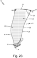
- FIG. 2B is a perspective view of fan blade 10 showing strip S of fan blade 10 with airfoil coating 30 removed.
- FIG. 2C is a perspective view of fan blade 10 showing overlap O between two strips S of fan blade 10.
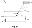
- FIG. 3A is a schematic view of a stream of liquid nitrogen 36 directed at tip coating 32.
- FIG. 3B is a perspective view of fan blade 10 showing airfoil coating 30 and tip coating 32 removed.
- FIGS. 1-3B will be discussed together.
- Fan blade 10 includes airfoil body 12, root 14, tip 16, platform 18, first side 20, second side 22, leading edge 24, trailing edge 26, substrate 28, airfoil coating 30, and tip coating 32.
- Liquid nitrogen blast system 34 includes liquid nitrogen 36, nozzle 38, pump 40, and reservoir 42.
- Fan blade 10 has airfoil body 12 forming the main body of fan blade 10. Root 14 is at a first end of airfoil body 12, and tip 16 is at a second end of airfoil body 12. Airfoil body 12 has a twisted airfoil shape. Platform 18 is between airfoil body 12 and root 14. First side 20 is at a first side of airfoil body 12 and extends from root 14 to tip 16, and second side 22 is at a second side of airfoil body 12 and extends from root 14 to tip 16. Leading edge 24 is at a first edge of airfoil body 12 formed by first side 20 and second side 22, leading edge 24 extending from root 14 to tip 16.
- Trailing edge 26 is at a second edge of airfoil body 12 formed by first side 20 and second side 22, trailing edge 26 extending from root to tip 16.
- Fan blade 10 may include a cover attached (e.g. with epoxy) to first side 20 of airfoil body 12 and/or a sheath attached (e.g. with epoxy) to leading edge 24.
- Fan blade 10 is made of aluminum alloy substrate 28, which is covered by airfoil coating 30 and tip coating 32.
- airfoil coating 30 covers first side 20 and second side 22 of airfoil body 12, platform 18, and a portion of root 14 adjacent airfoil body 12.
- Tip coating 32 covers tip 16 of airfoil body 12.
- airfoil coating 30 is comprised of three layers. A first chemical layer, or bond primer, is applied to substrate 28, which is already covered in an anodized bond coating, a second paint primer layer is applied to the first layer, and a third urethane top layer is applied to the second layer. The third layer is an erosion coating.
- tip coating 32 is a thermal plasma spray coating.
- airfoil coating 30 and tip coating 32 may be thermal spray, polyurethane, primers, epoxies, or any other suitable specialty coatings.
- Liquid nitrogen blast system 34 dispenses liquid nitrogen 36 from nozzle 38.
- Nozzle 38 may a non-rotating or rotating nozzle such that rotation of nozzle 38 is at least between 0 and about 1,000 RPM.
- Nozzle 38 may be a single-orifice nozzle or a multi-orifice nozzle.
- One or more orifices of nozzle 38 may be jeweled.
- Nozzle 38 is fluidly connected to pump 40 via tubing (not shown) such that liquid nitrogen 36 moves through tubing from reservoir 42 to pump 40 to nozzle 38.
- Pump 40 is a cryogenic pump for pressurizing liquid nitrogen 36. Pump 40 has a pressure between about 68.9 MPa (10,000 psi) and about 413.7 MPa (60,000 psi).
- the flow rate from nozzle 38 is determined by the pressure of pump 40 and the shape of and number of orifices in nozzle 38.
- Pump 40 is fluidly connected to reservoir 42, which holds liquid nitrogen 36.
- Liquid nitrogen blast system 34 may also include a robot and controller to manipulate the nozzle, a mount for fixing fan blade 10, a turntable for manipulation of fan blade 10, a sound enclosure, an exhaust system, and axillary equipment.
- Liquid nitrogen 36 is sprayed to remove airfoil coating 30 and tip coating 32 from fan blade 10.
- fan blade 10 is liquid nitrogen blasted, or liquid nitrogen 36 is discharged through nozzle 38 as a stream onto fan blade 10 at airfoil coating 30 to impact airfoil coating 30 (which is the material to be stripped from fan blade 10).
- Nozzle 38 is positioned to have a standoff distance D from fan blade 10, or the distance between nozzle 38 and fan blade 10, of at least between about 0.127 centimeter (0.050 inch) and 5.08 centimeters (2.0 inches).
- Nozzle 38 also has an angle of attack A, or angle with respect to fan blade 10, of at least between about 45 degrees and about 90 degrees.
- Airfoil coating 30 is lifted from substrate 28 of fan blade 10 by the pressurized stream of liquid nitrogen 36 hitting fan blade 10. Liquid nitrogen 36 goes underneath airfoil coating 30 to peel airfoil coating 30 away. More specifically, the first layer erodes off substrate 28 during the blast process and the second layer erodes or fractures at the same time as the first layer. The third layer exfoliates and is plowed away by the blast stream of liquid nitrogen 36. As a result, all three layers of airfoil coating 30 are removed at the same time. Nozzle 38 discharging liquid nitrogen 36 is traversed along fan blade 10 in direction of movement M to peel airfoil coating 30 off of substrate 28 as nozzle 38 traverses fan blade 10.
- Nozzle 38 traverses fan blade 10 at a speed of at least between about 1 mm/s and 50 mm/s. Nozzle 38 is moved along fan blade 10 to lift and peel airfoil coating 30 off of substrate 28 to reveal strips S (including S1 and S2) of substrate 28. A single pass of nozzle 38 reveals a strip S of substrate 28. Strips S may have a width W up to about 5.08 centimeters (2 inches). Nozzle 38 is moved along fan blade 10 such that strips S overlap to form overlap OL having a width WO.
- Nozzle 38 may be configured (e.g. single-orifice or multi-orifice, jeweled orifice, and rotating or non-rotating) based upon the desired width W of strip S or based upon the location of fan blade 10 that requires coating removal. If nozzle 38, for example, is a single-orifice nozzle with a fan-like spray pattern, nozzle 38 may not rotate. On the other hand, if nozzle 38, for example, is a multi-orifice nozzle, nozzle 38 is rotating.
- Nozzle 38 may traverse along fan blade 10 such that nozzle 38 traverses fan blade 10 in a first lateral direction with respect to fan blade 10 (from leading edge 24 to trailing edge 26 or from trailing edge 26 to leading edge 24). Subsequently, nozzle 38 is moved longitudinally with respect to fan blade 10 along fan blade 10 (up or down either tailing edge 26 or leading edge 24 depending on where nozzle 38 stopped after the previous pass along fan blade 10) to form a desired overlap OL. Nozzle 38 then traverses fan blade 10 in a second lateral direction with respect to fan blade 10 (from trailing edge 26 to leading edge 24 or from leading edge 34 to trailing edge 26) that is opposite the first lateral direction. Such a process continues until all of airfoil coating 30 is stripped from fan blade 10.
- nozzle 38 may traverse along fan blade 10 such that nozzle traverses fan blade 10 in a first longitudinal direction with respect to fan blade 10 (from tip 16 to platform 18, platform 18 to root 14, root 14 to platform 18, or from platform 18 to tip 16). Subsequently, nozzle 38 is moved laterally with respect to fan blade 10 along fan blade 10 (across either platform 18, root 14, or tip 16 depending on where nozzle 38 stopped after the previous pass along fan blade 10) to form a desired overlap OL. Nozzle 38 then traverses fan blade 10 in a second longitudinal direction with respect to fan blade 10 (from platform 18 to tip 16, from root 14 to platform 18, from platform 18 to root 14, or from tip 16 to platform 18) that is opposite the first longitudinal direction.
- nozzle 38 traverses fan blade 10 in a rastering pattern. Nozzle 38 also traverses fan blade 10 in an automated, programed, robot-controlled process. As such, parameters such as angle of attack A, stand-off distance D, pressure of pump 40, and the pattern of traversing fan blade 10 can be dictated, and repeated. Fan blade 10 can be oriented in any direction with respect to liquid nitrogen blast system 34.
- first strip S1 extends between leading edge 24 and trailing edge 26 and has a width W1 of about 5.08 centimeters (2 inches).
- Nozzle 38 is moved about 2.54 centimeters (1 inch) longitudinally along fan blade 10 to generate a desired overlap OL of about 2.54 cm (1 inch).
- nozzle 38 discharging liquid nitrogen 36 traverses fan blade 10 in a second lateral direction opposite the first lateral direction to form a second strip S2, which also has a width W2 of about 5.08 cm (2 inches), and an overlap OL between first strip S1 and second strip S2 having a width WO of about 2.54 cm (1 inch).
- Nozzle 38 continues to traverse fan blade 10 until all of airfoil coating 30 is stripped to reveal all of substrate 28 that was previously covered by airfoil coating 30.
- liquid nitrogen 36 is then discharged through nozzle 38 onto tip coating 32 on tip 16 of fan blade 10.
- Liquid nitrogen 36 freezes and shatters tip coating 32, or breaks up tip coating 32 into powder, to strip tip coating 32 from tip 16 of fan blade 10.
- Nozzle 38 discharging liquid nitrogen 36 is traversed along tip 16 of fan blade 10 in direction of movement M to remove all of tip coating 32 from tip 16 as nozzle 38 traverses tip 16 of fan blade 10.
- FIG. 3B after nozzle 38 discharging liquid nitrogen 36 has traversed all of fan blade 10 having either airfoil coating 30 or tip coating 32, fan blade 10 is free of airfoil coating 30 and tip coating 32. Fan blade 10 may then be re-coated. After the liquid nitrogen blasting is complete, the liquid nitrogen evaporates such that the only clean-up required is with respect to coatings 30 and 32.
- airfoil coatings are removed from fan blades using a plastic media blast process, which is a manual process that is time-consuming, often taking multiple hours to complete, and results in stock loss of the aluminum substrate.
- plastic media blast process introduces the possibility of human error, generally relying on visual indicators while moving along the fan blade.
- plastic media may become imbedded in the fan blade.
- water jet processes which can also be used to remove coatings, are time intensive, result in stock loss, and risk water getting into the fan blade.
- no process is approved to remove a thermal spray tip coating.
- Liquid nitrogen blasting allows airfoil coating 30 to be peeled off, or completely removed from, substrate 28, without eroding or damaging substrate 28. Likewise, liquid nitrogen blasting removes tip coating 32 without eroding or damaging substrate 28. As such, coatings 30 and 32 may be completely stripped from aluminum alloy substrate 28 of fan blade 10 with zero stock loss of substrate 28. Therefore, liquid nitrogen blasting of fan blades results in complete coating removal without any substrate erosion, or zero stock loss.
- liquid nitrogen blasting to remove coatings from fan blades is a much faster process, potentially taking only minutes to complete.
- Liquid nitrogen blasting can remove a coating to reveal strips of substrate having larger widths so that a large amount of coating can be removed very quickly, greatly reducing the time required to strip the fan blade. Additionally, because liquid nitrogen blasting is an automated, robot-controlled process, human error is reduced to yield a more controllable, repeatable, less variable process.
- Fan blades may have unsatisfactory, or non-conforming, coatings.
- coatings may have adhesion problems, such as delamination, dimples, nodules, or other imperfections. Unsatisfactory coatings may result during processing of the fan blade, or coatings may become unsatisfactory during flight of the aircraft. As such, fan blade 10 can be easily and quickly stripped of coatings 30 and 32 using liquid nitrogen blasting so that fan blade 10 can be reworked or refurbished with new coatings.
Landscapes
- Engineering & Computer Science (AREA)
- Mechanical Engineering (AREA)
- General Engineering & Computer Science (AREA)
- Chemical & Material Sciences (AREA)
- Materials Engineering (AREA)
- Structures Of Non-Positive Displacement Pumps (AREA)
- Application Of Or Painting With Fluid Materials (AREA)
- Chemical Kinetics & Catalysis (AREA)
- General Chemical & Material Sciences (AREA)
- Turbine Rotor Nozzle Sealing (AREA)
Claims (14)
- Verfahren zum Entfernen einer Beschichtung von einer Laufschaufel (10), umfassend:Abscheiden von flüssigem Stickstoff durch eine Düse (38) auf die Laufschaufel (10) an einer Beschichtung (30), um das Anheben der Beschichtung (30) von einem Substrat (28) der Laufschaufel (10) zu bewirken, wobei die Beschichtung (30) eine Schaufelprofilbeschichtung (30) ist, die 3 Schichten umfasst; undBewegen der Düse (38) entlang der Laufschaufel (10), um das Ablösen der Beschichtung (30) von dem Substrat (28) der Laufschaufel (10) zu bewirken, während die Düse (38) über die Laufschaufel (10) fährt; dadurch gekennzeichnet, dass die Düse (38) mit einer Kryopumpe (40) verbunden ist, die einen Druck zwischen etwa 68,9 MPa (10.000 psi) und etwa 413,7 MPa (60.000 psi) aufweist; und dadurch, dassdie Schritte des Abscheidens und Bewegens die erste Schicht, die zweite Schicht und die dritte Schicht gleichzeitig entfernen.
- Verfahren nach Anspruch 1, wobei die Laufschaufel eine Fanlaufschaufel (10) ist.
- Verfahren nach Anspruch 1 oder 2, wobei das Ablösen der Beschichtung (30) von dem Substrat (28) der Laufschaufel (10) das Ablösen der Beschichtung (30) von dem Substrat (28) der Laufschaufel (10) ohne Erodieren des Substrats (28) der Laufschaufel (10) beinhaltet.
- Verfahren nach Anspruch 1, 2 oder 3, ferner das Anordnen der Düse (38), so dass sie eine Abstandsentfernung (D) von der Laufschaufel (10) von mindestens zwischen etwa 0,127 cm (0,050 Zoll) und 5.08 cm (2,0 Zoll) aufweist, beinhaltend.
- Verfahren nach einem der vorstehenden Ansprüche, wobei das Bewegen der Düse (38) entlang der Laufschaufel (10) Folgendes beinhaltet:Bewegen der Laufschaufel (10) in einer ersten lateralen Richtung;Bewegen der Düse (38) in Längsrichtung entlang der Laufschaufel (10); undBewegen der Laufschaufel (10) in einer zweiten lateralen Richtung, die der ersten lateralen Richtung entgegengesetzt ist.
- Verfahren nach Anspruch 1 bis 4, wobei das Bewegen der Düse (38) entlang der Laufschaufel (10) Folgendes beinhaltet:Bewegen der Laufschaufel (10) in einer ersten Längsrichtung;Bewegen der Düse (38) lateral entlang der Laufschaufel (10); und Bewegen der Laufschaufel (10) in einer zweiten Längsrichtung, die der ersten Längsrichtung entgegengesetzt ist.
- Verfahren nach einem der vorstehenden Ansprüche, wobei die Düse (38) mindestens zwischen etwa 45 Grad und etwa 90 Grad von der Laufschaufel (10) abgewinkelt ist.
- Verfahren nach einem der vorstehenden Ansprüche, wobei die Düse (38) entlang der Laufschaufel (10) bewegt wird, um die Beschichtung (30) anzuheben und von dem Substrat (28) zu lösen, um Streifen (S) des Substrats (28) freizulegen, und wobei jeder Streifen (S) des Substrats durch einen einzigen Durchlauf der Düse (38) entlang der Laufschaufel (10) freigelegt wird, wobei jeder Streifen (S) eine Breite (width - W) von beispielsweise bis zu etwa 5,08 cm (2 Zoll) aufweist.
- Verfahren nach Anspruch 8, wobei die Düse (38) derart entlang der Laufschaufel (10) bewegt wird, dass sich die Streifen (S) überlappen.
- Verfahren nach einem der vorstehenden Ansprüche, wobei die Düse (38) rotierend oder nicht rotierend ist und die Düse (38) eine Einlochdüse oder eine Mehrlochdüse ist.
- Verfahren nach einem der vorstehenden Ansprüche, wobei das Substrat (28) ein Aluminiumlegierungssubstrat ist.
- Verfahren nach einem der vorstehenden Ansprüche, wobei die erste Schicht der Beschichtung (30) eine Haftungsgrundierung ist, die zweite Schicht der Beschichtung (30) eine Farbgrundierung ist und die dritte Schicht der Beschichtung (30) eine Urethan-Deckschicht ist.
- Verfahren nach einem der vorstehenden Ansprüche, ferner das Abscheiden von flüssigem Stickstoff durch die Düse (38) auf eine Spitzenbeschichtung (32) auf der Laufschaufel (10) beinhaltend, um das Absplittern der Spitzenbeschichtung (32) von der Spitze (16) der Laufschaufel (10) zu bewirken.
- Verfahren nach Anspruch 13, wobei die Spitzenbeschichtung (32) eine thermische Plasmaspritzbeschichtung ist.
Applications Claiming Priority (1)
| Application Number | Priority Date | Filing Date | Title |
|---|---|---|---|
| US15/971,722 US11346371B2 (en) | 2018-05-04 | 2018-05-04 | Method to strip coatings off of an aluminum alloy fan blade |
Publications (3)
| Publication Number | Publication Date |
|---|---|
| EP3564480A1 EP3564480A1 (de) | 2019-11-06 |
| EP3564480B1 true EP3564480B1 (de) | 2021-01-06 |
| EP3564480B8 EP3564480B8 (de) | 2021-04-07 |
Family
ID=66349330
Family Applications (1)
| Application Number | Title | Priority Date | Filing Date |
|---|---|---|---|
| EP19171907.9A Active EP3564480B8 (de) | 2018-05-04 | 2019-04-30 | Verfahren zum entfernen von beschichtungen von einer lüfterschaufel aus aluminiumlegierung |
Country Status (2)
| Country | Link |
|---|---|
| US (2) | US11346371B2 (de) |
| EP (1) | EP3564480B8 (de) |
Families Citing this family (2)
| Publication number | Priority date | Publication date | Assignee | Title |
|---|---|---|---|---|
| US11346371B2 (en) | 2018-05-04 | 2022-05-31 | Raytheon Technologies Corporation | Method to strip coatings off of an aluminum alloy fan blade |
| US12138745B2 (en) | 2023-03-22 | 2024-11-12 | Yield Engineering Systems, Inc. | Apparatus and method for coating removal |
Family Cites Families (32)
| Publication number | Priority date | Publication date | Assignee | Title |
|---|---|---|---|---|
| FR2579514B1 (fr) | 1985-03-26 | 1990-05-11 | Linde Ag | Procede d'ebarbage de pieces faconnees |
| DE4341869A1 (de) * | 1992-12-08 | 1994-06-09 | Flow Int Corp | Entfernung von harten Überzügen mit Ultrahochdruck-Flachstrahlen |
| US5733174A (en) | 1994-01-07 | 1998-03-31 | Lockheed Idaho Technologies Company | Method and apparatus for cutting, abrading, and drilling with sublimable particles and vaporous liquids |
| KR0165467B1 (ko) | 1995-10-31 | 1999-02-01 | 김광호 | 웨이퍼 디본더 및 이를 이용한 웨이퍼 디본딩법 |
| SG68035A1 (en) | 1997-03-27 | 1999-10-19 | Canon Kk | Method and apparatus for separating composite member using fluid |
| US6364971B1 (en) | 2000-01-20 | 2002-04-02 | Electric Power Research Institute | Apparatus and method of repairing turbine blades |
| US6622739B2 (en) * | 2001-03-12 | 2003-09-23 | Advanced Systems Technologies, Inc. | Method and apparatus for removal of coatings and oxidation from transit vehicles |
| US20030140950A1 (en) | 2002-01-29 | 2003-07-31 | Kim Yang Geun | Cryogenic methods for removing lead based paints from large steel structure |
| US20070023142A1 (en) | 2002-12-19 | 2007-02-01 | Lagraff John R | Airfoil refurbishment method |
| US8425085B2 (en) | 2006-04-16 | 2013-04-23 | Albeo Technologies, Inc. | Thermal management of LED-based lighting systems |
| US8021491B2 (en) | 2006-12-07 | 2011-09-20 | Lawrence Bernard Kool | Method for selectively removing coatings from metal substrates |
| US8083162B2 (en) | 2007-08-23 | 2011-12-27 | Liquajet L.L.C. | Method for micro-sizing organic, inorganic and engineered compounds |
| WO2009114297A2 (en) | 2008-03-03 | 2009-09-17 | Greenline Foods, Inc. | Automatic defect detector and rejecter |
| US9409383B2 (en) | 2008-12-22 | 2016-08-09 | Apple Inc. | Layer-specific energy distribution delamination |
| US8800145B2 (en) | 2008-12-30 | 2014-08-12 | Sikorsky Aircraft Corporation | Refurbishing method and system for a main rotor blade spar |
| US8950459B2 (en) | 2009-04-16 | 2015-02-10 | Suss Microtec Lithography Gmbh | Debonding temporarily bonded semiconductor wafers |
| FR2950271B1 (fr) | 2009-09-23 | 2011-12-09 | Air Liquide | Dispositif de distribution de jets de fluide cryogenique avec joint en polymere a coefficient de dilatation donne |
| FR2950277B1 (fr) | 2009-09-23 | 2012-01-13 | Air Liquide | Procede pour eliminer un revetement present sur la surface d'un recipient de gaz |
| US9085053B2 (en) * | 2009-12-22 | 2015-07-21 | United Technologies Corporation | In-situ turbine blade tip repair |
| US20110211965A1 (en) | 2010-02-26 | 2011-09-01 | United Technologies Corporation | Hollow fan blade |
| US9144882B2 (en) | 2012-04-04 | 2015-09-29 | Hypertherm, Inc. | Identifying liquid jet cutting system components |
| US9657570B2 (en) * | 2013-03-11 | 2017-05-23 | United Technologies Corporation | Pulse jet liquid gas cleaning system |
| ITBA20130021A1 (it) | 2013-03-12 | 2014-09-13 | Politecnico Di Bari | "processo criogenico per il recupero di materiali rigidi mono o poli-cristallini od amorfi rivestiti con materiali plastici" |
| US9150980B2 (en) | 2013-08-08 | 2015-10-06 | The Boeing Company | Method of removing a metal detail from a substrate |
| EP3033201A4 (de) * | 2013-08-14 | 2016-09-07 | United Technologies Corp | Wabenbeseitigung |
| US10344772B2 (en) * | 2013-11-26 | 2019-07-09 | United Technologies Corporation | Fan blade with composite cover and sacrificial filler |
| FR3025735B1 (fr) | 2014-09-17 | 2016-12-09 | Europe Tech | Procede de traitement d'une piece composite |
| EP3184735A3 (de) * | 2015-12-24 | 2017-10-04 | United Technologies Corporation | Lokale reparatur oder wiederaufarbeitung von polymeren erosionsbeschichtungen |
| US10138732B2 (en) | 2016-06-27 | 2018-11-27 | United Technologies Corporation | Blade shield removal and replacement |
| US11260421B2 (en) * | 2017-07-21 | 2022-03-01 | Raytheon Technologies Corporation | Method to strip and recoat erosion coatings applied to fan blades and structural guide vanes |
| US20190061073A1 (en) | 2017-08-25 | 2019-02-28 | United Technologies Corporation | Separating adhesively bonded lap joints |
| US11346371B2 (en) | 2018-05-04 | 2022-05-31 | Raytheon Technologies Corporation | Method to strip coatings off of an aluminum alloy fan blade |
-
2018
- 2018-05-04 US US15/971,722 patent/US11346371B2/en active Active
-
2019
- 2019-04-30 EP EP19171907.9A patent/EP3564480B8/de active Active
-
2022
- 2022-05-27 US US17/826,377 patent/US11814983B2/en active Active
Non-Patent Citations (1)
| Title |
|---|
| None * |
Also Published As
| Publication number | Publication date |
|---|---|
| EP3564480A1 (de) | 2019-11-06 |
| US11346371B2 (en) | 2022-05-31 |
| EP3564480B8 (de) | 2021-04-07 |
| US20190338789A1 (en) | 2019-11-07 |
| US11814983B2 (en) | 2023-11-14 |
| US20220282738A1 (en) | 2022-09-08 |
Similar Documents
| Publication | Publication Date | Title |
|---|---|---|
| US11814983B2 (en) | Method to strip coatings off of an aluminum alloy fan blade | |
| EP0430856B1 (de) | Ablösung von plasmagespritzten oder gesinterten Beschichtungen mittels eines Wasserstrahls | |
| EP2439377B1 (de) | Verfahren zur Herstellung eines Kühllochs einer Turbinenschaufel | |
| EP3078760B1 (de) | Lasergestützte oxidentfernung | |
| CA1256753A (en) | Method for preventing closure of cooling holes in hollow air cooled turbine engine components during application of a plasma spray coating | |
| US6042879A (en) | Method for preparing an apertured article to be recoated | |
| JP6174008B2 (ja) | パルスレーザを用いてターボシャフトエンジンブレードを洗浄し剥離するための方法 | |
| CN111253076A (zh) | 通过旋转单面蚀刻制造高精度超薄玻璃的方法及其玻璃 | |
| EP3315745B1 (de) | Turbinenschaufelwartungsverfahren | |
| EP2576138B2 (de) | Verfahren zur entfernung von keramikbeschichtungen mit einem strahlverfahren mit co² in festem zustand | |
| EP1464722B1 (de) | Verfahren zum Auftragen von Umweltschutz- und Haftbeschichtung für Strömungskanalteile von Turbinen | |
| JP5987033B2 (ja) | 耐熱塗膜の熱劣化層の除去装置 | |
| EP2770082B1 (de) | Verfahren zum Maskieren einer Oberfläche | |
| EP3282034A1 (de) | Aluminiumgebläseschaufelspitze, die für thermisches sprühablagern von schleifstoffen durch laserablation vorbereitet ist | |
| US8007563B1 (en) | Waterjet removal of coverings from cables | |
| JPH04210279A (ja) | 高圧噴射水による部品の被膜のはぎとり方法 | |
| TWI668364B (zh) | 渦輪葉片的修補方法 | |
| US7299732B1 (en) | Honeycomb removal | |
| Staschik et al. | Stripping of thermal sprayed oxid coatings by means of laser techniques water jet and a newly developed hybrid method | |
| Zheng et al. | A mathematical model for surface roughness of ship hull grit blasting | |
| Vaccari | Waterjet Strips Tenacious Coatings | |
| KR20190048040A (ko) | 내성코팅층 제거방법 | |
| JP2025074508A (ja) | 塗装方法及び塗装システム | |
| CN118339364A (zh) | 选择性地从涡轮叶片的冷却凹部中移除覆层 | |
| CN104668913A (zh) | 不锈钢管三层聚丙烯防腐管的制造设备及其方法 |
Legal Events
| Date | Code | Title | Description |
|---|---|---|---|
| PUAI | Public reference made under article 153(3) epc to a published international application that has entered the european phase |
Free format text: ORIGINAL CODE: 0009012 |
|
| STAA | Information on the status of an ep patent application or granted ep patent |
Free format text: STATUS: THE APPLICATION HAS BEEN PUBLISHED |
|
| AK | Designated contracting states |
Kind code of ref document: A1 Designated state(s): AL AT BE BG CH CY CZ DE DK EE ES FI FR GB GR HR HU IE IS IT LI LT LU LV MC MK MT NL NO PL PT RO RS SE SI SK SM TR |
|
| AX | Request for extension of the european patent |
Extension state: BA ME |
|
| STAA | Information on the status of an ep patent application or granted ep patent |
Free format text: STATUS: REQUEST FOR EXAMINATION WAS MADE |
|
| 17P | Request for examination filed |
Effective date: 20200506 |
|
| RBV | Designated contracting states (corrected) |
Designated state(s): AL AT BE BG CH CY CZ DE DK EE ES FI FR GB GR HR HU IE IS IT LI LT LU LV MC MK MT NL NO PL PT RO RS SE SI SK SM TR |
|
| GRAP | Despatch of communication of intention to grant a patent |
Free format text: ORIGINAL CODE: EPIDOSNIGR1 |
|
| STAA | Information on the status of an ep patent application or granted ep patent |
Free format text: STATUS: GRANT OF PATENT IS INTENDED |
|
| INTG | Intention to grant announced |
Effective date: 20200716 |
|
| GRAS | Grant fee paid |
Free format text: ORIGINAL CODE: EPIDOSNIGR3 |
|
| GRAA | (expected) grant |
Free format text: ORIGINAL CODE: 0009210 |
|
| STAA | Information on the status of an ep patent application or granted ep patent |
Free format text: STATUS: THE PATENT HAS BEEN GRANTED |
|
| AK | Designated contracting states |
Kind code of ref document: B1 Designated state(s): AL AT BE BG CH CY CZ DE DK EE ES FI FR GB GR HR HU IE IS IT LI LT LU LV MC MK MT NL NO PL PT RO RS SE SI SK SM TR |
|
| REG | Reference to a national code |
Ref country code: GB Ref legal event code: FG4D |
|
| REG | Reference to a national code |
Ref country code: AT Ref legal event code: REF Ref document number: 1352576 Country of ref document: AT Kind code of ref document: T Effective date: 20210115 Ref country code: CH Ref legal event code: EP |
|
| REG | Reference to a national code |
Ref country code: DE Ref legal event code: R096 Ref document number: 602019002050 Country of ref document: DE |
|
| REG | Reference to a national code |
Ref country code: IE Ref legal event code: FG4D |
|
| REG | Reference to a national code |
Ref country code: DE Ref legal event code: R081 Ref document number: 602019002050 Country of ref document: DE Owner name: RAYTHEON TECHNOLOGIES CORPORATION, FARMINGTON, US Free format text: FORMER OWNER: UNITED TECHNOLOGIES CORPORATION, FARMINGTON, CONN., US Ref country code: DE Ref legal event code: R081 Ref document number: 602019002050 Country of ref document: DE Owner name: RTX CORPORATION (N.D.GES.D. STAATES DELAWARE),, US Free format text: FORMER OWNER: UNITED TECHNOLOGIES CORPORATION, FARMINGTON, CONN., US |
|
| REG | Reference to a national code |
Ref country code: CH Ref legal event code: PK Free format text: BERICHTIGUNG B8 |
|
| RAP2 | Party data changed (patent owner data changed or rights of a patent transferred) |
Owner name: RAYTHEON TECHNOLOGIES CORPORATION |
|
| REG | Reference to a national code |
Ref country code: NL Ref legal event code: MP Effective date: 20210106 |
|
| REG | Reference to a national code |
Ref country code: AT Ref legal event code: MK05 Ref document number: 1352576 Country of ref document: AT Kind code of ref document: T Effective date: 20210106 |
|
| REG | Reference to a national code |
Ref country code: LT Ref legal event code: MG9D |
|
| PG25 | Lapsed in a contracting state [announced via postgrant information from national office to epo] |
Ref country code: LT Free format text: LAPSE BECAUSE OF FAILURE TO SUBMIT A TRANSLATION OF THE DESCRIPTION OR TO PAY THE FEE WITHIN THE PRESCRIBED TIME-LIMIT Effective date: 20210106 Ref country code: PT Free format text: LAPSE BECAUSE OF FAILURE TO SUBMIT A TRANSLATION OF THE DESCRIPTION OR TO PAY THE FEE WITHIN THE PRESCRIBED TIME-LIMIT Effective date: 20210506 Ref country code: NO Free format text: LAPSE BECAUSE OF FAILURE TO SUBMIT A TRANSLATION OF THE DESCRIPTION OR TO PAY THE FEE WITHIN THE PRESCRIBED TIME-LIMIT Effective date: 20210406 Ref country code: HR Free format text: LAPSE BECAUSE OF FAILURE TO SUBMIT A TRANSLATION OF THE DESCRIPTION OR TO PAY THE FEE WITHIN THE PRESCRIBED TIME-LIMIT Effective date: 20210106 Ref country code: FI Free format text: LAPSE BECAUSE OF FAILURE TO SUBMIT A TRANSLATION OF THE DESCRIPTION OR TO PAY THE FEE WITHIN THE PRESCRIBED TIME-LIMIT Effective date: 20210106 Ref country code: GR Free format text: LAPSE BECAUSE OF FAILURE TO SUBMIT A TRANSLATION OF THE DESCRIPTION OR TO PAY THE FEE WITHIN THE PRESCRIBED TIME-LIMIT Effective date: 20210407 Ref country code: BG Free format text: LAPSE BECAUSE OF FAILURE TO SUBMIT A TRANSLATION OF THE DESCRIPTION OR TO PAY THE FEE WITHIN THE PRESCRIBED TIME-LIMIT Effective date: 20210406 |
|
| PG25 | Lapsed in a contracting state [announced via postgrant information from national office to epo] |
Ref country code: SE Free format text: LAPSE BECAUSE OF FAILURE TO SUBMIT A TRANSLATION OF THE DESCRIPTION OR TO PAY THE FEE WITHIN THE PRESCRIBED TIME-LIMIT Effective date: 20210106 Ref country code: RS Free format text: LAPSE BECAUSE OF FAILURE TO SUBMIT A TRANSLATION OF THE DESCRIPTION OR TO PAY THE FEE WITHIN THE PRESCRIBED TIME-LIMIT Effective date: 20210106 Ref country code: LV Free format text: LAPSE BECAUSE OF FAILURE TO SUBMIT A TRANSLATION OF THE DESCRIPTION OR TO PAY THE FEE WITHIN THE PRESCRIBED TIME-LIMIT Effective date: 20210106 Ref country code: PL Free format text: LAPSE BECAUSE OF FAILURE TO SUBMIT A TRANSLATION OF THE DESCRIPTION OR TO PAY THE FEE WITHIN THE PRESCRIBED TIME-LIMIT Effective date: 20210106 Ref country code: AT Free format text: LAPSE BECAUSE OF FAILURE TO SUBMIT A TRANSLATION OF THE DESCRIPTION OR TO PAY THE FEE WITHIN THE PRESCRIBED TIME-LIMIT Effective date: 20210106 |
|
| PG25 | Lapsed in a contracting state [announced via postgrant information from national office to epo] |
Ref country code: IS Free format text: LAPSE BECAUSE OF FAILURE TO SUBMIT A TRANSLATION OF THE DESCRIPTION OR TO PAY THE FEE WITHIN THE PRESCRIBED TIME-LIMIT Effective date: 20210506 |
|
| REG | Reference to a national code |
Ref country code: DE Ref legal event code: R097 Ref document number: 602019002050 Country of ref document: DE |
|
| PG25 | Lapsed in a contracting state [announced via postgrant information from national office to epo] |
Ref country code: EE Free format text: LAPSE BECAUSE OF FAILURE TO SUBMIT A TRANSLATION OF THE DESCRIPTION OR TO PAY THE FEE WITHIN THE PRESCRIBED TIME-LIMIT Effective date: 20210106 Ref country code: CZ Free format text: LAPSE BECAUSE OF FAILURE TO SUBMIT A TRANSLATION OF THE DESCRIPTION OR TO PAY THE FEE WITHIN THE PRESCRIBED TIME-LIMIT Effective date: 20210106 Ref country code: SM Free format text: LAPSE BECAUSE OF FAILURE TO SUBMIT A TRANSLATION OF THE DESCRIPTION OR TO PAY THE FEE WITHIN THE PRESCRIBED TIME-LIMIT Effective date: 20210106 |
|
| PLBE | No opposition filed within time limit |
Free format text: ORIGINAL CODE: 0009261 |
|
| STAA | Information on the status of an ep patent application or granted ep patent |
Free format text: STATUS: NO OPPOSITION FILED WITHIN TIME LIMIT |
|
| PG25 | Lapsed in a contracting state [announced via postgrant information from national office to epo] |
Ref country code: DK Free format text: LAPSE BECAUSE OF FAILURE TO SUBMIT A TRANSLATION OF THE DESCRIPTION OR TO PAY THE FEE WITHIN THE PRESCRIBED TIME-LIMIT Effective date: 20210106 Ref country code: SK Free format text: LAPSE BECAUSE OF FAILURE TO SUBMIT A TRANSLATION OF THE DESCRIPTION OR TO PAY THE FEE WITHIN THE PRESCRIBED TIME-LIMIT Effective date: 20210106 Ref country code: RO Free format text: LAPSE BECAUSE OF FAILURE TO SUBMIT A TRANSLATION OF THE DESCRIPTION OR TO PAY THE FEE WITHIN THE PRESCRIBED TIME-LIMIT Effective date: 20210106 Ref country code: MC Free format text: LAPSE BECAUSE OF FAILURE TO SUBMIT A TRANSLATION OF THE DESCRIPTION OR TO PAY THE FEE WITHIN THE PRESCRIBED TIME-LIMIT Effective date: 20210106 |
|
| 26N | No opposition filed |
Effective date: 20211007 |
|
| PG25 | Lapsed in a contracting state [announced via postgrant information from national office to epo] |
Ref country code: LU Free format text: LAPSE BECAUSE OF NON-PAYMENT OF DUE FEES Effective date: 20210430 |
|
| REG | Reference to a national code |
Ref country code: BE Ref legal event code: MM Effective date: 20210430 |
|
| PG25 | Lapsed in a contracting state [announced via postgrant information from national office to epo] |
Ref country code: ES Free format text: LAPSE BECAUSE OF FAILURE TO SUBMIT A TRANSLATION OF THE DESCRIPTION OR TO PAY THE FEE WITHIN THE PRESCRIBED TIME-LIMIT Effective date: 20210106 Ref country code: AL Free format text: LAPSE BECAUSE OF FAILURE TO SUBMIT A TRANSLATION OF THE DESCRIPTION OR TO PAY THE FEE WITHIN THE PRESCRIBED TIME-LIMIT Effective date: 20210106 |
|
| PG25 | Lapsed in a contracting state [announced via postgrant information from national office to epo] |
Ref country code: SI Free format text: LAPSE BECAUSE OF FAILURE TO SUBMIT A TRANSLATION OF THE DESCRIPTION OR TO PAY THE FEE WITHIN THE PRESCRIBED TIME-LIMIT Effective date: 20210106 |
|
| PG25 | Lapsed in a contracting state [announced via postgrant information from national office to epo] |
Ref country code: IT Free format text: LAPSE BECAUSE OF FAILURE TO SUBMIT A TRANSLATION OF THE DESCRIPTION OR TO PAY THE FEE WITHIN THE PRESCRIBED TIME-LIMIT Effective date: 20210106 Ref country code: IE Free format text: LAPSE BECAUSE OF NON-PAYMENT OF DUE FEES Effective date: 20210430 |
|
| PG25 | Lapsed in a contracting state [announced via postgrant information from national office to epo] |
Ref country code: IS Free format text: LAPSE BECAUSE OF FAILURE TO SUBMIT A TRANSLATION OF THE DESCRIPTION OR TO PAY THE FEE WITHIN THE PRESCRIBED TIME-LIMIT Effective date: 20210506 |
|
| PG25 | Lapsed in a contracting state [announced via postgrant information from national office to epo] |
Ref country code: BE Free format text: LAPSE BECAUSE OF NON-PAYMENT OF DUE FEES Effective date: 20210430 |
|
| REG | Reference to a national code |
Ref country code: CH Ref legal event code: PL |
|
| PG25 | Lapsed in a contracting state [announced via postgrant information from national office to epo] |
Ref country code: LI Free format text: LAPSE BECAUSE OF NON-PAYMENT OF DUE FEES Effective date: 20220430 Ref country code: CH Free format text: LAPSE BECAUSE OF NON-PAYMENT OF DUE FEES Effective date: 20220430 |
|
| P01 | Opt-out of the competence of the unified patent court (upc) registered |
Effective date: 20230521 |
|
| PG25 | Lapsed in a contracting state [announced via postgrant information from national office to epo] |
Ref country code: NL Free format text: LAPSE BECAUSE OF NON-PAYMENT OF DUE FEES Effective date: 20210206 Ref country code: CY Free format text: LAPSE BECAUSE OF FAILURE TO SUBMIT A TRANSLATION OF THE DESCRIPTION OR TO PAY THE FEE WITHIN THE PRESCRIBED TIME-LIMIT Effective date: 20210106 |
|
| PG25 | Lapsed in a contracting state [announced via postgrant information from national office to epo] |
Ref country code: HU Free format text: LAPSE BECAUSE OF FAILURE TO SUBMIT A TRANSLATION OF THE DESCRIPTION OR TO PAY THE FEE WITHIN THE PRESCRIBED TIME-LIMIT; INVALID AB INITIO Effective date: 20190430 |
|
| PG25 | Lapsed in a contracting state [announced via postgrant information from national office to epo] |
Ref country code: MK Free format text: LAPSE BECAUSE OF FAILURE TO SUBMIT A TRANSLATION OF THE DESCRIPTION OR TO PAY THE FEE WITHIN THE PRESCRIBED TIME-LIMIT Effective date: 20210106 |
|
| PG25 | Lapsed in a contracting state [announced via postgrant information from national office to epo] |
Ref country code: TR Free format text: LAPSE BECAUSE OF FAILURE TO SUBMIT A TRANSLATION OF THE DESCRIPTION OR TO PAY THE FEE WITHIN THE PRESCRIBED TIME-LIMIT Effective date: 20210106 |
|
| PG25 | Lapsed in a contracting state [announced via postgrant information from national office to epo] |
Ref country code: MT Free format text: LAPSE BECAUSE OF FAILURE TO SUBMIT A TRANSLATION OF THE DESCRIPTION OR TO PAY THE FEE WITHIN THE PRESCRIBED TIME-LIMIT Effective date: 20210106 |
|
| PGFP | Annual fee paid to national office [announced via postgrant information from national office to epo] |
Ref country code: DE Payment date: 20250319 Year of fee payment: 7 |
|
| REG | Reference to a national code |
Ref country code: DE Ref legal event code: R081 Ref document number: 602019002050 Country of ref document: DE Owner name: RTX CORPORATION (N.D.GES.D. STAATES DELAWARE),, US Free format text: FORMER OWNER: RAYTHEON TECHNOLOGIES CORPORATION, FARMINGTON, CT, US |
|
| PGFP | Annual fee paid to national office [announced via postgrant information from national office to epo] |
Ref country code: GB Payment date: 20260319 Year of fee payment: 8 |
|
| PGFP | Annual fee paid to national office [announced via postgrant information from national office to epo] |
Ref country code: FR Payment date: 20260319 Year of fee payment: 8 |