EP3564460B1 - Roof window with reinforcement in frame top member - Google Patents
Roof window with reinforcement in frame top member Download PDFInfo
- Publication number
- EP3564460B1 EP3564460B1 EP19171526.7A EP19171526A EP3564460B1 EP 3564460 B1 EP3564460 B1 EP 3564460B1 EP 19171526 A EP19171526 A EP 19171526A EP 3564460 B1 EP3564460 B1 EP 3564460B1
- Authority
- EP
- European Patent Office
- Prior art keywords
- profile
- roof window
- window according
- base portion
- flange portion
- Prior art date
- Legal status (The legal status is an assumption and is not a legal conclusion. Google has not performed a legal analysis and makes no representation as to the accuracy of the status listed.)
- Active
Links
Images


Classifications
-
- E—FIXED CONSTRUCTIONS
- E04—BUILDING
- E04D—ROOF COVERINGS; SKY-LIGHTS; GUTTERS; ROOF-WORKING TOOLS
- E04D13/00—Special arrangements or devices in connection with roof coverings; Protection against birds; Roof drainage ; Sky-lights
- E04D13/03—Sky-lights; Domes; Ventilating sky-lights
-
- E—FIXED CONSTRUCTIONS
- E04—BUILDING
- E04D—ROOF COVERINGS; SKY-LIGHTS; GUTTERS; ROOF-WORKING TOOLS
- E04D13/00—Special arrangements or devices in connection with roof coverings; Protection against birds; Roof drainage ; Sky-lights
- E04D13/03—Sky-lights; Domes; Ventilating sky-lights
- E04D13/0305—Supports or connecting means for sky-lights of flat or domed shape
- E04D13/031—Supports or connecting means for sky-lights of flat or domed shape characterised by a frame for connection to an inclined roof
-
- E—FIXED CONSTRUCTIONS
- E04—BUILDING
- E04D—ROOF COVERINGS; SKY-LIGHTS; GUTTERS; ROOF-WORKING TOOLS
- E04D13/00—Special arrangements or devices in connection with roof coverings; Protection against birds; Roof drainage ; Sky-lights
- E04D13/03—Sky-lights; Domes; Ventilating sky-lights
- E04D13/0305—Supports or connecting means for sky-lights of flat or domed shape
-
- E—FIXED CONSTRUCTIONS
- E04—BUILDING
- E04D—ROOF COVERINGS; SKY-LIGHTS; GUTTERS; ROOF-WORKING TOOLS
- E04D13/00—Special arrangements or devices in connection with roof coverings; Protection against birds; Roof drainage ; Sky-lights
- E04D13/03—Sky-lights; Domes; Ventilating sky-lights
- E04D13/035—Sky-lights; Domes; Ventilating sky-lights characterised by having movable parts
Definitions
- the present invention relates to a roof window, particularly for installation in an inclined roof surface, comprising a frame having a plurality of frame members including a frame top member with an outer surface, and a reinforcement member formed as a separate element and connected to the outer surface of the frame top member in a mounted condition, the reinforcement member having a length dimension and a width dimension configured to cover a substantial part of the outer surface of the frame top member.
- the stationary frame When installing roof windows in a roof, the stationary frame is often mounted at a relatively early point in time relative to the finishing work including the subsequent connection of the sash and other components. The reasons for this are many, including the need for adapting the surrounding roofing on the external side and fitting lining panels on the internal side. During this period, the frame sits unprotected on the roof, and while the aperture which will later accommodate the sash is typically covered by a tarpaulin or the like, the frame itself is exposed in the roof surface. Installers, roofers, construction workers, architects and other people walk on the roof, and it sometimes happens that the top of the roof window is stepped upon, either involuntarily or in the belief that this is unproblematic. This applies in particular to the top member of the frame.
- the frame top member is an element with some longitudinal extension but of a relatively slender thickness, and the sash is still not present to provide a counter force
- the load from the weight leads to a bending moment that may be quite substantial, in addition to smudging the outer surface of the frame, which is less critical, the bending moment can at worst lead to cracks in the material of the frame top member and/or in the inner surface which will be visible in the mounted condition.
- the reinforcement member is made of a piece of metal having such length, thickness and width dimensions that the reinforcement member covers a substantial part of the outer side of the corresponding frame top member.
- metal is a well-known material with excellent strength properties, and which may furthermore be re-cycled after the life-span of the roof window
- a reinforcement member is most often fastened to the frame top member at the manufacturing site and hence adds to the weight of the overall roof window.
- the metal reinforcement member constitutes a cold bridge in the mounted condition, thus detracting from the thermal properties of the roof window
- EP0962606 A1 discloses a roof window with a capping strip having on its lower surface an insulation layer.
- the reinforcement member of such a roof window comprises at least a first profile of a metal material and a second profile of a plastic material releasably connected to each other.
- the plastic second profile contributes to improving the insulating properties of the reinforcement member, while the metal first profile ensures that in particular resistance to bending is achieved.
- the respective dimensions of the first profile and the second profile may be chosen appropriately.
- the length of the first and second profile is substantially identical, and the width of the second profile is larger than the width of the first profile by a factor in the range 2 to 10, preferably 4 to 8.
- the plastic second profile form the majority of the area of the reinforcement member ensures adequate insulating properties while retaining satisfactory strength. Even in such cases where the metal first profile only constitutes 10-20% of the total width of the reinforcement member, the mechanical properties have proven sufficient for normally occurring incidents.
- the first profile comprises a base portion configured to extend substantially in parallel with the outer surface of the frame top member in the mounted condition and a leg portion extending substantially perpendicular to the base portion and comprising a first flange portion and a second flange portion, the first flange portion extending between the base portion and an upper edge and the second flange portion extending between the upper edge and a lower edge.
- the first profile is provided with engagement means to cooperate with receiving means in the second profile.
- engagement means may be placed also on the second profile and the receiving means in the first profile, as long as the required releasable connection is formed in an operative manner.
- the engagement means of the first profile comprises at least one perpendicular leg section extending from the base portion and at least one protruding leg section in conjunction with the perpendicular leg section and extending substantially in parallel with the base portion, preferably two perpendicular leg sections and two protruding leg sections are provided, the protruding leg sections preferably extending away from each other. In this manner, a form-locking engagement is achieved between the first and second profile, thus eliminating the risk of untimely release of the engagement.
- the reinforcement member comprises a third profile in the form of a foam plate, preferably of an elastic polymer foam material having a thickness of 2 to 5 mm. This provides for additional insulation and protection of the frame top member. It is preferred that the foam plate is positioned on the side of the second profile opposite to the first profile and faces the outer surface of the frame top member in the mounted condition.
- the material of the metal first profile may in principle be chosen in any suitable manner. It is preferred that the material is steel, preferably having a thickness of 0.5 to 1.5 mm, preferably coated with an alloy such as Al-Zn, and preferably formed by rolling. This provides for a durable component having excellent manufacturing and wear-resistant properties.
- the plastic material of the second profile may in principle be any material able to fulfil the requirements to durability, UV resistance etc.
- a suitable material and dimension has been found in Acrylonitrile butadiene styrene (ABS), preferably having a thickness of 2 to 5 mm, preferably reinforced by glass fibre, preferably having an E-modulus of at least 4 GPa and a tensile strength of at least 50 MPa as tested according to EN / ISO 527-2.
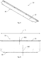
- FIG. 1 the general configuration of a roof window which is top-hinged during normal operation and which pivots for cleaning is shown.
- a window is shown and described in further detail in Applicant's European patent No. 0 733 146 B1 , the contents of which are hereby incorporated by reference.
- the roof window here comprises a primary frame in the form of a stationary frame 1 configured for installation in an inclined roof surface.
- At least one secondary frame is connected to the stationary frame 1, in the embodiment shown a first secondary frame in the form of a sash 2 carrying a pane 4, and a second secondary frame in the form of an intermediate frame 3.
- the intermediate frame 3 is fastened to the stationary frame at a top mounting fitting 5, and the sash 2 is hinged at the top of the roof window, via the intermediate frame 3 to the stationary frame 1, to render the roof window top-hung during normal operation.
- the sash 2 is also pivotally connected to the intermediate frame 3 in order to be able to rotate the sash 2 to provide access to the outside of the pane 4, for instance for cleaning purposes.
- the intermediate frame 3 is provided with a frame hinge part 6 of pivot hinge fitting.
- the sash 2 is provided with the counterpart sash hinge part of the pivot hinge fitting.
- a lifting device 9 is provided to assist in the opening of the window, that is, bringing the secondary frame or frames to an angled position relative to the primary frame.
- the user operates the operating device of the window in the form of a handle 7 at the bottom member of the sash 2.
- the roof window is provided with a ventilation device 8 acting to allow passage of air also in the closed position of the window.
- top-hung roof window is shown and described, the principles underlying the invention are generally applicable to all types of roof windows though, including roof windows pivoting about a central axis, about an axis offset from the centre, and top-hung skylights which do not pivot for cleaning, and fixed, i.e. non-openable skylights.
- a prior art reinforcement member 10' is indicated on the top member of the frame 1.
- the reinforcement member 10' is made fully of metal.
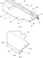
- a reinforcement member 10 of a roof window will be described with reference to Figs 3 to 8 . It is understood that the reinforcement member 10 in its mounted condition is connected to the outer surface of the frame top member of a roof window as the one shown in Fig. 1 , and that the drawing figures referred to show the reinforcement members for reasons of easy readability. Furthermore, it is recognised that the reinforcement member 10 has a length dimension and a width dimension configured to cover a substantial part of the outer surface of the frame top member. As roof windows come in different sizes, it is understood that the person skilled in the art will be able to select such suitable length and width dimensions without undue burden.
- the reinforcement member 10 comprises at least a first profile 20 of a metal material and a second profile 30 of a plastic material releasably connected to each other.
- the length L of the first profile 20 and the second profile 30 is substantially identical, thus corresponding to a major part of the length of the frame top member.
- the width W2 of the second profile 30 is larger than the width W1 of the first profile 20 by a factor in the range 2 to 10, preferably 4 to 8.
- the combined width of the respective width dimensions W1 and W2 is larger than the resultant width of the assembled reinforcement member.
- the first profile 20 comprises a base portion 21 configured to extend substantially in parallel with the outer surface of the frame top member in the mounted condition and a leg portion extending substantially perpendicular to the base portion 21 and comprising a first flange portion 22 and a second flange portion 24, the first flange portion 22 extending between the base portion 21 and an upper edge 23a and the second flange portion 24 extending between the upper edge 23a and a lower edge 23b.
- transitions between the individual portions of the first profile are rounded to increase the strength properties even further, but also to provide better handling characteristics, as the lack of sharp edges will reduce the risk of damage to people and property.
- the rounded edges are an advantage, since metal forming techniques such as rolling may be used.
- the metal material of the first profile 20 is here steel, for instance in the form of sheet metal with a suitable thickness of for instance 0.5 to 1.5 mm.
- the sheet metal is preferably coated with an alloy such as Al-Zn to increase durability and resistance to corrosion.
- the distance between the upper edge 23a and the lower edge 23b is larger than the distance between the upper edge 23a and the base portion 21 such that the second flange portion 24 protrudes below the base portion 21.
- this entails that the second flange portion 24 may be positioned around the transition between the outer surface of the frame top member and an inner surface of the frame top member.
- a third flange portion 26 is provided in conjunction with the second flange portion 24, extending from the lower edge 23b up to substantially an underside of the base portion 21. This increases the strength of the first profile 20 even further.
- a hook portion 25 is in the embodiment shown formed in conjunction with the second flange portion 24 and also the third flange portion 26, in at least one longitudinal end, here both ends, of the first profile 20 to extend beyond the length L of the first profile 20, measured on the parts other than the hook portion or portions 25.
- the first profile 20 is provided with engagement means 27 to cooperate with receiving means 37 in the second profile 30. This will be described in further detail below.
- the engagement means 27 of the first profile 20 comprises at least one perpendicular leg section 28a extending from the base portion 21 and at least one protruding leg section 29a in conjunction with the perpendicular leg section 28a and extending substantially in parallel with the base portion 21.
- the leg sections have been formed by cut-out and bent sections of the base portion 21, confer the presence of openings 21a and 21b in the base portion 21.
- the second profile 30 comprises, in the embodiment shown, a substantially plane base portion 31 in which a number of apertures are provided, including at least a plurality of holes 34, 35 for receiving fastening means, said plurality preferably including openings and/or cut-outs 32, 33 for accommodating parts of the roof window.
- fastening means may include screws with appropriate head size to fasten the reinforcement member 10 to the outer surface of the frame top member.
- the plastic material of the second profile 30 is here chosen as an Acrylonitrile butadiene styrene (ABS).
- ABS Acrylonitrile butadiene styrene
- the thickness of the second profile is chosen in accordance with the material parameters and the desired properties.
- the second profile 30 may be reinforced by glass fibre, and should preferably show an E-modulus of at least 4 GPa and a tensile strength of at least 50 MPa as tested according to EN / ISO 527-2. Typically, a thickness in the range 2 to 5 mm will be suitable.
- One of the plurality of apertures here includes an aperture 37 forming the receiving means cooperating with the engagement means 27 of the first profile 20.
- the aperture 37 forming the receiving means has such dimensions that at least one perpendicular leg section 28a, 28b fits in the aperture but the at least one protruding leg section 29a, 29b at least partly protrudes beyond the aperture 37.
- the foam plate 40 is positioned on the side of the second profile 30 opposite to first profile 20 and faces the outer surface of the frame top member in the mounted condition.
- the foam plate 40 also covers the protruding leg sections 29a, 29b in the mounted condition.
- the connection between the foam plate 40 and the second profile 30 may be carried out in any suitable manner, for instance by an adhesive; however, the entire reinforcement member 10 is fastened to the outer surface of the frame top member, and the foam plate 40 is placed entirely below the second profile 30 in the mounted condition.
- the reinforcement member 10 is provided on the roof window according to the invention by first forming the first profile 20, the second profile 30 and optionally the third profile or foam plate 40 individually. Subsequently, the first profile 20 is releasably connected to the second profile 30, in the embodiment shown by engaging the engagement means 27 of the first profile with the receiving means of the second profile by inserting the leg sections 28a, 28b, 29a, 29b into the aperture 37 in the second profile 30.
- the foam plate 40 is either attached to the second profile before or after the engagement.
- the reinforcement member 10 is now in the form of a separate element and will be fastened to the frame top member to provide the finished roof window.
- the properties of the reinforcement member 10 in respect of its insulating properties vary depending of the actual dimensions, but improvements in the overall U-value for the member falls within a range of 0.005 to 0.03 W/m 2 K as described in more detail in the following examples I-III.
Landscapes
- Engineering & Computer Science (AREA)
- Architecture (AREA)
- Civil Engineering (AREA)
- Structural Engineering (AREA)
- Wing Frames And Configurations (AREA)
- Roof Covering Using Slabs Or Stiff Sheets (AREA)
- Door And Window Frames Mounted To Openings (AREA)
Priority Applications (1)
| Application Number | Priority Date | Filing Date | Title |
|---|---|---|---|
| PL19171526T PL3564460T3 (pl) | 2018-04-30 | 2019-04-29 | Okno dachowe ze wzmocnieniem w członie górnym ościeżnicy |
Applications Claiming Priority (1)
| Application Number | Priority Date | Filing Date | Title |
|---|---|---|---|
| DKPA201870253A DK180455B1 (en) | 2018-04-30 | 2018-04-30 | Roof window with reinforcement in frame top member |
Publications (2)
| Publication Number | Publication Date |
|---|---|
| EP3564460A1 EP3564460A1 (en) | 2019-11-06 |
| EP3564460B1 true EP3564460B1 (en) | 2021-05-26 |
Family
ID=66323721
Family Applications (1)
| Application Number | Title | Priority Date | Filing Date |
|---|---|---|---|
| EP19171526.7A Active EP3564460B1 (en) | 2018-04-30 | 2019-04-29 | Roof window with reinforcement in frame top member |
Country Status (6)
| Country | Link |
|---|---|
| EP (1) | EP3564460B1 (pl) |
| CN (1) | CN110130590B (pl) |
| DK (1) | DK180455B1 (pl) |
| ES (1) | ES2879424T3 (pl) |
| HU (1) | HUE054485T2 (pl) |
| PL (1) | PL3564460T3 (pl) |
Cited By (1)
| Publication number | Priority date | Publication date | Assignee | Title |
|---|---|---|---|---|
| EP4257772A1 (en) | 2022-03-31 | 2023-10-11 | VKR Holding A/S | A roof window arrangement comprising a plurality of window units and a common frame, and method of installing such a roof window arrangement |
Family Cites Families (6)
| Publication number | Priority date | Publication date | Assignee | Title |
|---|---|---|---|---|
| DE2752414C2 (de) * | 1977-11-24 | 1980-01-24 | Blefa Ag, 5910 Kreuztal | Dachfenster |
| US5553425A (en) * | 1994-11-17 | 1996-09-10 | Wasco Products, Inc. | Flashing and counterflashing |
| NL1009317C2 (nl) * | 1998-06-04 | 1999-12-07 | Redland Dakprod Bv | Schuin dak met dakraam en indekdeel. |
| GB2430943B (en) * | 2005-09-21 | 2010-08-04 | Viridian Concepts Ltd | Roof flashing connections comprising resilient member |
| IT1399707B1 (it) * | 2010-04-26 | 2013-04-26 | Palladio Spa | Serramento a taglio termico naturale |
| DK179827B1 (en) * | 2015-08-04 | 2019-07-17 | Vkr Holding A/S | An insulating member, a roof window and a method for insulating a roof window |
-
2018
- 2018-04-30 DK DKPA201870253A patent/DK180455B1/en active IP Right Grant
-
2019
- 2019-04-28 CN CN201910350473.7A patent/CN110130590B/zh active Active
- 2019-04-29 PL PL19171526T patent/PL3564460T3/pl unknown
- 2019-04-29 EP EP19171526.7A patent/EP3564460B1/en active Active
- 2019-04-29 HU HUE19171526A patent/HUE054485T2/hu unknown
- 2019-04-29 ES ES19171526T patent/ES2879424T3/es active Active
Cited By (1)
| Publication number | Priority date | Publication date | Assignee | Title |
|---|---|---|---|---|
| EP4257772A1 (en) | 2022-03-31 | 2023-10-11 | VKR Holding A/S | A roof window arrangement comprising a plurality of window units and a common frame, and method of installing such a roof window arrangement |
Also Published As
| Publication number | Publication date |
|---|---|
| HUE054485T2 (hu) | 2021-09-28 |
| PL3564460T3 (pl) | 2021-11-22 |
| DK201870253A1 (en) | 2020-01-07 |
| ES2879424T3 (es) | 2021-11-22 |
| EP3564460A1 (en) | 2019-11-06 |
| CN110130590B (zh) | 2022-07-05 |
| CN110130590A (zh) | 2019-08-16 |
| DK180455B1 (en) | 2021-05-06 |
Similar Documents
| Publication | Publication Date | Title |
|---|---|---|
| CA2137499C (en) | Retrofit 20 minutes fire door kit | |
| EP3916187B1 (en) | A roof window installation system, and a method of installing a roof window | |
| EP2290188A1 (en) | Flood barrier and assembly | |
| EP3564460B1 (en) | Roof window with reinforcement in frame top member | |
| WO2020071932A1 (en) | Roof window frame with installation set and flashing assembly | |
| US8146312B2 (en) | Garage door and a method of making a garage door | |
| EP2055860B1 (en) | A method and covering kit for sound dampening a roof window | |
| US5428925A (en) | Fiberglass bulkhead door assembly | |
| EP2088256B1 (en) | Roof window frame and method of manufacturing thereof | |
| US7165793B2 (en) | Door jamb security plate | |
| DK181781B1 (en) | Mounting bracket for a roof window | |
| KR20160047265A (ko) | 건축용 내외벽의 표면 마감 외장재를 지지하는 외장재 지지구 및 이를 이용한 내외벽 표면 마감 외장재 설치 구조 | |
| DK182137B1 (en) | A flashing member and a method for making a flashing member | |
| US7213374B2 (en) | Hinge for an enclosure | |
| US9249613B2 (en) | Method for making a window and an opening window | |
| KR102062080B1 (ko) | 조립식 지붕 패널의 결속유닛 | |
| GB2254356A (en) | Cut-resistant roller shutter | |
| EP1558824B1 (en) | Burglar proof roof window | |
| CN215254020U (zh) | 一种屋面检修门 | |
| EP1375798A1 (en) | Access door for gates | |
| KR200293428Y1 (ko) | 천정 점검구 | |
| KR200173320Y1 (ko) | 오버헤드 도어용 패널 | |
| KR200272205Y1 (ko) | 여닫이식 유리문용 상, 하부 고정판 마감구조 | |
| JP3027910B2 (ja) | 出窓底板 | |
| KR0133385Y1 (ko) | 철재문용 보강문틀 |
Legal Events
| Date | Code | Title | Description |
|---|---|---|---|
| PUAI | Public reference made under article 153(3) epc to a published international application that has entered the european phase |
Free format text: ORIGINAL CODE: 0009012 |
|
| STAA | Information on the status of an ep patent application or granted ep patent |
Free format text: STATUS: THE APPLICATION HAS BEEN PUBLISHED |
|
| AK | Designated contracting states |
Kind code of ref document: A1 Designated state(s): AL AT BE BG CH CY CZ DE DK EE ES FI FR GB GR HR HU IE IS IT LI LT LU LV MC MK MT NL NO PL PT RO RS SE SI SK SM TR |
|
| AX | Request for extension of the european patent |
Extension state: BA ME |
|
| STAA | Information on the status of an ep patent application or granted ep patent |
Free format text: STATUS: REQUEST FOR EXAMINATION WAS MADE |
|
| 17P | Request for examination filed |
Effective date: 20200219 |
|
| RBV | Designated contracting states (corrected) |
Designated state(s): AL AT BE BG CH CY CZ DE DK EE ES FI FR GB GR HR HU IE IS IT LI LT LU LV MC MK MT NL NO PL PT RO RS SE SI SK SM TR |
|
| GRAP | Despatch of communication of intention to grant a patent |
Free format text: ORIGINAL CODE: EPIDOSNIGR1 |
|
| STAA | Information on the status of an ep patent application or granted ep patent |
Free format text: STATUS: GRANT OF PATENT IS INTENDED |
|
| RIC1 | Information provided on ipc code assigned before grant |
Ipc: E04D 13/03 20060101AFI20201112BHEP |
|
| INTG | Intention to grant announced |
Effective date: 20201214 |
|
| GRAS | Grant fee paid |
Free format text: ORIGINAL CODE: EPIDOSNIGR3 |
|
| GRAA | (expected) grant |
Free format text: ORIGINAL CODE: 0009210 |
|
| STAA | Information on the status of an ep patent application or granted ep patent |
Free format text: STATUS: THE PATENT HAS BEEN GRANTED |
|
| AK | Designated contracting states |
Kind code of ref document: B1 Designated state(s): AL AT BE BG CH CY CZ DE DK EE ES FI FR GB GR HR HU IE IS IT LI LT LU LV MC MK MT NL NO PL PT RO RS SE SI SK SM TR |
|
| REG | Reference to a national code |
Ref country code: GB Ref legal event code: FG4D |
|
| REG | Reference to a national code |
Ref country code: CH Ref legal event code: EP |
|
| REG | Reference to a national code |
Ref country code: AT Ref legal event code: REF Ref document number: 1396356 Country of ref document: AT Kind code of ref document: T Effective date: 20210615 |
|
| REG | Reference to a national code |
Ref country code: DE Ref legal event code: R096 Ref document number: 602019004823 Country of ref document: DE |
|
| REG | Reference to a national code |
Ref country code: IE Ref legal event code: FG4D |
|
| REG | Reference to a national code |
Ref country code: NL Ref legal event code: FP |
|
| REG | Reference to a national code |
Ref country code: LT Ref legal event code: MG9D |
|
| REG | Reference to a national code |
Ref country code: HU Ref legal event code: AG4A Ref document number: E054485 Country of ref document: HU |
|
| PG25 | Lapsed in a contracting state [announced via postgrant information from national office to epo] |
Ref country code: BG Free format text: LAPSE BECAUSE OF FAILURE TO SUBMIT A TRANSLATION OF THE DESCRIPTION OR TO PAY THE FEE WITHIN THE PRESCRIBED TIME-LIMIT Effective date: 20210826 Ref country code: HR Free format text: LAPSE BECAUSE OF FAILURE TO SUBMIT A TRANSLATION OF THE DESCRIPTION OR TO PAY THE FEE WITHIN THE PRESCRIBED TIME-LIMIT Effective date: 20210526 Ref country code: LT Free format text: LAPSE BECAUSE OF FAILURE TO SUBMIT A TRANSLATION OF THE DESCRIPTION OR TO PAY THE FEE WITHIN THE PRESCRIBED TIME-LIMIT Effective date: 20210526 Ref country code: FI Free format text: LAPSE BECAUSE OF FAILURE TO SUBMIT A TRANSLATION OF THE DESCRIPTION OR TO PAY THE FEE WITHIN THE PRESCRIBED TIME-LIMIT Effective date: 20210526 |
|
| REG | Reference to a national code |
Ref country code: ES Ref legal event code: FG2A Ref document number: 2879424 Country of ref document: ES Kind code of ref document: T3 Effective date: 20211122 |
|
| PG25 | Lapsed in a contracting state [announced via postgrant information from national office to epo] |
Ref country code: GR Free format text: LAPSE BECAUSE OF FAILURE TO SUBMIT A TRANSLATION OF THE DESCRIPTION OR TO PAY THE FEE WITHIN THE PRESCRIBED TIME-LIMIT Effective date: 20210827 Ref country code: IS Free format text: LAPSE BECAUSE OF FAILURE TO SUBMIT A TRANSLATION OF THE DESCRIPTION OR TO PAY THE FEE WITHIN THE PRESCRIBED TIME-LIMIT Effective date: 20210926 Ref country code: NO Free format text: LAPSE BECAUSE OF FAILURE TO SUBMIT A TRANSLATION OF THE DESCRIPTION OR TO PAY THE FEE WITHIN THE PRESCRIBED TIME-LIMIT Effective date: 20210826 Ref country code: LV Free format text: LAPSE BECAUSE OF FAILURE TO SUBMIT A TRANSLATION OF THE DESCRIPTION OR TO PAY THE FEE WITHIN THE PRESCRIBED TIME-LIMIT Effective date: 20210526 Ref country code: PT Free format text: LAPSE BECAUSE OF FAILURE TO SUBMIT A TRANSLATION OF THE DESCRIPTION OR TO PAY THE FEE WITHIN THE PRESCRIBED TIME-LIMIT Effective date: 20210927 Ref country code: SE Free format text: LAPSE BECAUSE OF FAILURE TO SUBMIT A TRANSLATION OF THE DESCRIPTION OR TO PAY THE FEE WITHIN THE PRESCRIBED TIME-LIMIT Effective date: 20210526 Ref country code: RS Free format text: LAPSE BECAUSE OF FAILURE TO SUBMIT A TRANSLATION OF THE DESCRIPTION OR TO PAY THE FEE WITHIN THE PRESCRIBED TIME-LIMIT Effective date: 20210526 |
|
| PG25 | Lapsed in a contracting state [announced via postgrant information from national office to epo] |
Ref country code: SK Free format text: LAPSE BECAUSE OF FAILURE TO SUBMIT A TRANSLATION OF THE DESCRIPTION OR TO PAY THE FEE WITHIN THE PRESCRIBED TIME-LIMIT Effective date: 20210526 Ref country code: EE Free format text: LAPSE BECAUSE OF FAILURE TO SUBMIT A TRANSLATION OF THE DESCRIPTION OR TO PAY THE FEE WITHIN THE PRESCRIBED TIME-LIMIT Effective date: 20210526 Ref country code: DK Free format text: LAPSE BECAUSE OF FAILURE TO SUBMIT A TRANSLATION OF THE DESCRIPTION OR TO PAY THE FEE WITHIN THE PRESCRIBED TIME-LIMIT Effective date: 20210526 Ref country code: SM Free format text: LAPSE BECAUSE OF FAILURE TO SUBMIT A TRANSLATION OF THE DESCRIPTION OR TO PAY THE FEE WITHIN THE PRESCRIBED TIME-LIMIT Effective date: 20210526 Ref country code: RO Free format text: LAPSE BECAUSE OF FAILURE TO SUBMIT A TRANSLATION OF THE DESCRIPTION OR TO PAY THE FEE WITHIN THE PRESCRIBED TIME-LIMIT Effective date: 20210526 |
|
| REG | Reference to a national code |
Ref country code: DE Ref legal event code: R097 Ref document number: 602019004823 Country of ref document: DE |
|
| PLBE | No opposition filed within time limit |
Free format text: ORIGINAL CODE: 0009261 |
|
| STAA | Information on the status of an ep patent application or granted ep patent |
Free format text: STATUS: NO OPPOSITION FILED WITHIN TIME LIMIT |
|
| 26N | No opposition filed |
Effective date: 20220301 |
|
| PG25 | Lapsed in a contracting state [announced via postgrant information from national office to epo] |
Ref country code: IS Free format text: LAPSE BECAUSE OF FAILURE TO SUBMIT A TRANSLATION OF THE DESCRIPTION OR TO PAY THE FEE WITHIN THE PRESCRIBED TIME-LIMIT Effective date: 20210926 Ref country code: AL Free format text: LAPSE BECAUSE OF FAILURE TO SUBMIT A TRANSLATION OF THE DESCRIPTION OR TO PAY THE FEE WITHIN THE PRESCRIBED TIME-LIMIT Effective date: 20210526 |
|
| REG | Reference to a national code |
Ref country code: AT Ref legal event code: UEP Ref document number: 1396356 Country of ref document: AT Kind code of ref document: T Effective date: 20210526 |
|
| PG25 | Lapsed in a contracting state [announced via postgrant information from national office to epo] |
Ref country code: MC Free format text: LAPSE BECAUSE OF FAILURE TO SUBMIT A TRANSLATION OF THE DESCRIPTION OR TO PAY THE FEE WITHIN THE PRESCRIBED TIME-LIMIT Effective date: 20210526 Ref country code: LU Free format text: LAPSE BECAUSE OF NON-PAYMENT OF DUE FEES Effective date: 20220429 |
|
| PG25 | Lapsed in a contracting state [announced via postgrant information from national office to epo] |
Ref country code: IE Free format text: LAPSE BECAUSE OF NON-PAYMENT OF DUE FEES Effective date: 20220429 |
|
| PG25 | Lapsed in a contracting state [announced via postgrant information from national office to epo] |
Ref country code: MK Free format text: LAPSE BECAUSE OF FAILURE TO SUBMIT A TRANSLATION OF THE DESCRIPTION OR TO PAY THE FEE WITHIN THE PRESCRIBED TIME-LIMIT Effective date: 20210526 Ref country code: CY Free format text: LAPSE BECAUSE OF FAILURE TO SUBMIT A TRANSLATION OF THE DESCRIPTION OR TO PAY THE FEE WITHIN THE PRESCRIBED TIME-LIMIT Effective date: 20210526 |
|
| PG25 | Lapsed in a contracting state [announced via postgrant information from national office to epo] |
Ref country code: TR Free format text: LAPSE BECAUSE OF FAILURE TO SUBMIT A TRANSLATION OF THE DESCRIPTION OR TO PAY THE FEE WITHIN THE PRESCRIBED TIME-LIMIT Effective date: 20210526 |
|
| PG25 | Lapsed in a contracting state [announced via postgrant information from national office to epo] |
Ref country code: MT Free format text: LAPSE BECAUSE OF FAILURE TO SUBMIT A TRANSLATION OF THE DESCRIPTION OR TO PAY THE FEE WITHIN THE PRESCRIBED TIME-LIMIT Effective date: 20210526 |
|
| PGFP | Annual fee paid to national office [announced via postgrant information from national office to epo] |
Ref country code: PL Payment date: 20250314 Year of fee payment: 7 Ref country code: CZ Payment date: 20250328 Year of fee payment: 7 |
|
| PGFP | Annual fee paid to national office [announced via postgrant information from national office to epo] |
Ref country code: DE Payment date: 20250305 Year of fee payment: 7 |
|
| PGFP | Annual fee paid to national office [announced via postgrant information from national office to epo] |
Ref country code: ES Payment date: 20250508 Year of fee payment: 7 |
|
| PGFP | Annual fee paid to national office [announced via postgrant information from national office to epo] |
Ref country code: HU Payment date: 20250327 Year of fee payment: 7 |
|
| PGFP | Annual fee paid to national office [announced via postgrant information from national office to epo] |
Ref country code: CH Payment date: 20250501 Year of fee payment: 7 |
|
| PGFP | Annual fee paid to national office [announced via postgrant information from national office to epo] |
Ref country code: AT Payment date: 20250325 Year of fee payment: 7 |
|
| PGFP | Annual fee paid to national office [announced via postgrant information from national office to epo] |
Ref country code: GB Payment date: 20260312 Year of fee payment: 8 |
|
| PGFP | Annual fee paid to national office [announced via postgrant information from national office to epo] |
Ref country code: BE Payment date: 20260317 Year of fee payment: 8 Ref country code: IT Payment date: 20260320 Year of fee payment: 8 |
|
| PGFP | Annual fee paid to national office [announced via postgrant information from national office to epo] |
Ref country code: NL Payment date: 20260317 Year of fee payment: 8 |
|
| PGFP | Annual fee paid to national office [announced via postgrant information from national office to epo] |
Ref country code: FR Payment date: 20260323 Year of fee payment: 8 |