EP3564174A1 - Openable elevator car wall panels - Google Patents
Openable elevator car wall panels Download PDFInfo
- Publication number
- EP3564174A1 EP3564174A1 EP18305553.2A EP18305553A EP3564174A1 EP 3564174 A1 EP3564174 A1 EP 3564174A1 EP 18305553 A EP18305553 A EP 18305553A EP 3564174 A1 EP3564174 A1 EP 3564174A1
- Authority
- EP
- European Patent Office
- Prior art keywords
- elevator car
- elevator
- wall panels
- connecting element
- wall panel
- Prior art date
- Legal status (The legal status is an assumption and is not a legal conclusion. Google has not performed a legal analysis and makes no representation as to the accuracy of the status listed.)
- Granted
Links
Images


Classifications
-
- B—PERFORMING OPERATIONS; TRANSPORTING
- B66—HOISTING; LIFTING; HAULING
- B66B—ELEVATORS; ESCALATORS OR MOVING WALKWAYS
- B66B11/00—Main component parts of lifts in, or associated with, buildings or other structures
- B66B11/02—Cages, i.e. cars
- B66B11/0226—Constructional features, e.g. walls assembly, decorative panels, comfort equipment, thermal or sound insulation
- B66B11/0253—Fixation of wall panels
-
- B—PERFORMING OPERATIONS; TRANSPORTING
- B66—HOISTING; LIFTING; HAULING
- B66B—ELEVATORS; ESCALATORS OR MOVING WALKWAYS
- B66B11/00—Main component parts of lifts in, or associated with, buildings or other structures
- B66B11/02—Cages, i.e. cars
- B66B11/0206—Car frames
-
- B—PERFORMING OPERATIONS; TRANSPORTING
- B66—HOISTING; LIFTING; HAULING
- B66B—ELEVATORS; ESCALATORS OR MOVING WALKWAYS
- B66B11/00—Main component parts of lifts in, or associated with, buildings or other structures
- B66B11/02—Cages, i.e. cars
- B66B11/0226—Constructional features, e.g. walls assembly, decorative panels, comfort equipment, thermal or sound insulation
-
- B—PERFORMING OPERATIONS; TRANSPORTING
- B66—HOISTING; LIFTING; HAULING
- B66B—ELEVATORS; ESCALATORS OR MOVING WALKWAYS
- B66B11/00—Main component parts of lifts in, or associated with, buildings or other structures
- B66B11/02—Cages, i.e. cars
- B66B11/0226—Constructional features, e.g. walls assembly, decorative panels, comfort equipment, thermal or sound insulation
- B66B11/0246—Maintenance features
Definitions
- the subject matter disclosed herein generally relates to elevator car wall panels and, more particularly, elevator car panel systems that allow for ease of opening such panels.
- Elevator systems are used to transport passengers within buildings between floors of the building. Elevators include various components located within an elevator shaft (either affixed to the shaft or on an exterior of an elevator car). From time to time, maintenance is performed upon such components, such as inspection, repair, replacement, etc., as appreciated by those of skill in the art.
- elevator car wall panel systems include an elevator car frame, at least two wall panels pivotally connected to the frame, a connecting element operably connecting the at least two wall panels, and an actuation element operably connected to the connecting element, wherein the actuation element is operable to transition the at least two wall panels from a closed state to an open state.
- further embodiments of the elevator car wall panel systems may include a locking element arranged to lock the at least two wall panels in the closed state.
- further embodiments of the elevator car wall panel systems may include that the connecting element is a rigid rod.
- each wall panel is pivotally connected to the connecting element by a respective connector.
- each connector comprises a bracket and a connector extension.
- each connector extension is a part of the connecting element.
- further embodiments of the elevator car wall panel systems may include that the actuation element comprises at least one sliding pivot and at least one rotating pivot.
- elevator cars are provided that include the elevator car wall panel systems of any of the above described embodiments.
- further embodiments of the elevator cars may include that the elevator car includes a passenger space, wherein the at least two wall panels are aesthetic panels of the passenger space.
- further embodiments of the elevator cars may include that the connecting element is located at at least one of a ceiling and a floor of the elevator car.
- elevator systems that include the elevator cars as described in the above embodiments, wherein the elevator car is positioned within an elevator shaft of the elevator system.
- further embodiments of the elevator systems may include that when the at least two wall panels are opened, at least a portion of the wall panels extends into the elevator shaft.
- further embodiments of the elevator systems may include at least one elevator component located within the elevator shaft, wherein when the at least two wall panels are opened, the at least one elevator component is accessible from the passenger space.
- FIG. 1 is a perspective view of an elevator system 101 including an elevator car 103, a counterweight 105, a roping 107, a guide rail 109, a machine 111, a position encoder 113, and a controller 115.
- the elevator car 103 and counterweight 105 are connected to each other by the roping 107.
- the roping 107 may include or be configured as, for example, ropes, steel cables, and/or coated-steel belts.
- the counterweight 105 is configured to balance a load of the elevator car 103 and is configured to facilitate movement of the elevator car 103 concurrently and in an opposite direction with respect to the counterweight 105 within an elevator shaft 117 and along the guide rail 109.
- the roping 107 engages the machine 111, which is part of an overhead structure of the elevator system 101.
- the machine 111 is configured to control movement between the elevator car 103 and the counterweight 105.
- the position encoder 113 may be mounted on an upper sheave of a speed-governor system 119 and may be configured to provide position signals related to a position of the elevator car 103 within the elevator shaft 117. In other embodiments, the position encoder 113 may be directly mounted to a moving component of the machine 111, or may be located in other positions and/or configurations as known in the art.
- the controller 115 is located, as shown, in a controller room 121 of the elevator shaft 117 and is configured to control the operation of the elevator system 101, and particularly the elevator car 103.
- the controller 115 may provide drive signals to the machine 111 to control the acceleration, deceleration, leveling, stopping, etc. of the elevator car 103.
- the controller 115 may also be configured to receive position signals from the position encoder 113.
- the elevator car 103 may stop at one or more landings 125 as controlled by the controller 115.
- the controller 115 can be located and/or configured in other locations or positions within the elevator system 101.
- the machine 111 may include a motor or similar driving mechanism.
- the machine 111 is configured to include an electrically driven motor.
- the power supply for the motor may be any power source, including a power grid, which, in combination with other components, is supplied to the motor.
- a roping system elevator systems that employ other methods and mechanisms of moving an elevator car within an elevator shaft may employ embodiments of the present disclosure.
- FIG. 1 is merely a non-limiting example presented for illustrative and explanatory purposes.
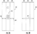
- FIGS. 2A and 2B schematic illustrations of elevator car wall panels 227, 229 that can employ embodiments described herein are shown.
- FIG. 2A shows a front elevation schematic view of a first elevator car wall panel 227.
- FIG. 2B shows a front elevation schematic view of a second elevator car wall panel 229.
- the first elevator car wall panel 227 includes subpanels 231, 233, wherein a first subpanel 231 includes a control section 243 of the elevator car and second subpanels 233 form aesthetic portions of the elevator car wall panel 227.
- the first subpanel 231 and the second subpanels 233 are configured to form a wall of an elevator car.
- the subpanels 231, 233 are parts of a solid or continuous elevator car wall panel, and thus are fixedly connected or are subparts of a continuous wall.
- the second elevator car wall panel 229 is formed with a number of subpanels 235, which may each be aesthetic panels (i.e., not including operational or functional aspects).
- the second subpanels 233 of the first elevator car wall panel 227 include associated handrails 237, 239.
- the second elevator car wall panel 229 includes a respective handrail 241 mounted thereto.
- the handrails 237, 239, 241 are mounted to the respective subpanels 233, 235 of the elevator car wall panels 227, 229 and provide users or passengers of the elevator to have a handrail to provide support or other function.
- ends of the handrails 237, 239, 241 may be fixedly attached to, mounted to, and supported by the respective subpanels 233, 235.
- the first subpanel 231 of the first elevator car wall panel 227 includes an operation or control section 243.
- the control section 243 includes a number of buttons that are used to enable a passenger to select a destination floor, and may also include emergency buttons, or other buttons as known in the art.
- the first subpanel 231 may further include other electronic elements, such as speakers, displays, etc., as will be appreciated by those of skill in the art.
- the elevator car wall panels can be fixedly and semi-permanently installed to an elevator car structural panel or frame. For example, screws, bolts, or other fasteners can be used to fasten the wall panels to the elevator car structural panel.
- screws, bolts, or other fasteners can be used to fasten the wall panels to the elevator car structural panel.
- such configurations may not allow easy changing and/or replacement of such elevator car wall panels and/or access to components located behind the wall panels.
- embodiments provided herein are directed to elevator car wall panels and associated systems that enable easy opening and operation to grant access to elements/components located behind the wall panels, thus avoiding a need for a mechanic to enter an elevator shaft to access such elements/components.
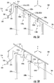
- FIGS. 3A-3B schematic illustrations of an elevator car panel system 300 of an elevator car 302 in accordance with an embodiment of the present disclosure are shown.
- FIG. 3A illustrates the elevator car panel system 300 in a first or closed state
- FIG. 3B illustrates the elevator car panel system 300 in a second or open state.
- the views of FIGS. 3A-3B are top-down plan views of the elevator car 302 which defines a passenger space 304.
- the elevator car 302 includes a frame 306 and a number of wall panels 308a, 308b, 308c movably attached to the frame 306.
- the wall panels 308a, 308b, 308c are aesthetic panels that surround and define the passenger space 304.
- An elevator car door (not shown) provides access to the passenger space 304 of the elevator car 302.
- the elevator car door is represented by a car door sill 310, along which the elevator car door may translate (open/close).
- Each wall panel 308a, 308b, 308c is pivotally mounted to the frame 306 at a respective pivot 312a, 312b, 312c. Further, each wall panel 308a, 308b, 308c is operably connected to a connecting element 314, such as a support rod or other rigid body.
- the connecting element 314 is operable by an actuation element 316 that is operable to actuate, move, translate, etc. the connecting element 314 to, in turn, open (or close) the wall panels 308a, 308b, 308c, as described herein.
- the connecting element 314 may be located at a top or bottom of the frame 306 (e.g., proximate a floor or ceiling of the elevator car 302). Although shown with the connecting element 314 arranged relatively on the interior of the car frame 306, in other embodiments, the connecting element may be located above the car frame or even located on the exterior of the car frame, i.e., located on the elevator shaft side of the car frame.
- Each wall panel 308a, 308b, 308c is operably connected to the connecting element 314 by a respective connector 318a, 318b, 318c.
- the connectors 318a, 318b, 318c may be brackets or similar structures that allow for the movement of the connecting element 314 to force or urge the wall panels 308a, 308b, 308c to move about the respective pivots 312a, 312b, 312c, as shown in FIG. 3B .
- the actuation element 316 can be rotated or actuated to apply a force on the connecting element 314.
- the connecting element 314 will translate or otherwise move, thus applying a force on each of the wall panels 308a, 308b, 308c through the connectors 318a, 318b, 318c.
- the connecting element 314 moves from a first position ( FIG. 3A ) to a second position ( FIG. 3B )
- the wall panels 308a, 308b, 308c will open, as shown in FIG. 3B .
- a mechanic or other authorized person may access components or elements located behind the wall panels 308a, 308b, 308c.
- the elevator car panel system 300 may be locked or secured such that the wall panels 308a, 308b, 308c cannot be opened, thus preventing unauthorized access.
- the elevator car panel system 300 may be unlocked and then the actuation element 316 may be operated to open the wall panels 308a, 308b, 308c.
- FIGS. 4A-4B schematic illustrations of an elevator car panel system 400 of an elevator car 402 in accordance with an embodiment of the present disclosure are shown.
- FIG. 4A illustrates the elevator car panel system 400 in a first or closed state
- FIG. 4B illustrates the elevator car panel system 400 in a second or open state.
- the illustrations are top-down plan views of the elevator car 402 which defines a passenger space 404, and an elevator shaft 417 is shown relative to the elevator car 402.
- the elevator car 402 includes a frame 406 and a number of wall panels 408a, 408b, 408c movably attached to the frame 406.
- the wall panels 408a, 408b, 408c are aesthetic panels that surround and define the passenger space 404.
- Each wall panel 408a, 408b, 408c is pivotally mounted to the frame 406 at a respective pivot 412a, 412b, 412c. Further, each wall panel 408a, 408b, 408c is operably connected to a connecting element 414, such as a support rod or other rigid body.
- the connecting element 414 is operable by an actuation element, not shown, that is operable to actuate, move, translate, etc. the connecting element 414 to, in turn, open (or close) the wall panels 408a, 408b, 408c, as described herein.
- the connecting element 414 may be located at a top or bottom of the frame 406 (e.g., proximate a floor or ceiling of the elevator car 402). Although shown with the connecting element 414 arranged relatively on the interior of the car frame 406, in other embodiments, the connecting element may be located above the car frame or even located on the exterior of the car frame, i.e., located on the elevator shaft side of the car frame.
- Each wall panel 408a, 408b, 408c is operably connected to the connecting element 414 by a respective connector 418a, 418b, 418c.
- the connectors 418a, 418b, 418c may be brackets or similar structures that allow for the movement of the connecting element 414 to force or urge the wall panels 408a, 408b, 408c to move about the respective pivots 412a, 412b, 412c, as shown in FIG. 4B .
- the connecting element 414 is actuated or operated, the wall panels 408a, 408b, 408c are opened by rotations about the respective pivots 412a, 412b, 412c.
- the connecting element 414 translates or otherwise moves, thus applying a force on each of the wall panels 408a, 408b, 408c through the connectors 418a, 418b, 418c.
- the connecting element 414 moves from a first position ( FIG. 4A ) to a second position ( FIG. 4B )
- the wall panels 408a, 408b, 408c will open, as shown in FIG. 4B .
- a mechanic or other authorized person may access components or elements located behind the wall panels 408a, 408b, 408c.
- a portion of the wall panels 408a, 408b, 408c may extend into the elevator shaft 417.
- a person may access the elevator shaft 417 and components thereof. That is, in some embodiments, after opening the wall panels 408a, 408b, 408c, a person may gain access to components in the elevator shaft 417 such as guide rails, electrical or electronic components, exterior components of the elevator car 402, etc. Such access is granted from the passenger space 404 of the elevator car 402, and thus a person is not required to enter the elevator shaft 417 to gain access thereto.
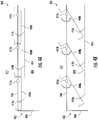
- FIGS. 5A-5B schematic, kinematic illustrations of an elevator car panel system 500 of an elevator car in accordance with an embodiment of the present disclosure are shown.
- FIG. 5A illustrates the elevator car panel system 500 in a first or closed state
- FIG. 5B illustrates the elevator car panel system 500 in a second or open state.
- FIGS. 5A-5B are schematic views from an exterior position viewing wall panels 508a, 508b that are movably attached to a frame 506.
- element 520 indicates a fixed connection to the frame 506
- element 522 indicates a rotating pivot
- element 524 indicates a sliding pivot.
- Each wall panel 508a, 508b is pivotally mounted to the frame 506 at a respective pivot 512a, 512b, with the pivots 512a, 512b being rotating pivots 522. Further, each wall panel 508a, 508b is operably connected to a connecting element 514, such as a support rod or other rigid body. As shown in FIGS. 5A-5B , the wall panels 508a, 508b are connected to the connecting element 514 by respective connectors 518a, 518b. As shown, the connectors 518a, 518b include a bracket 526a, 526b and a connector extension 528a, 528b.
- the brackets 526a, 526b and the connector extensions 528a, 528b form a rotatable connection between the connecting element 514 and the respective wall panels 508a, 508b.
- the connector extensions 528a, 528b are part of the connecting element 514.
- Part of the wall panels 508a, 508b is connected to the frame 506 by respective pivots 512a, 512b, which are rotating pivots 522.
- the pivots 512a, 512b are at last partially fixedly connected to the frame 506.
- the connecting element 514 is operable by an actuation element 516 that is operable to actuate, move, translate, etc. the connecting element 514 to, in turn, open (or close) the wall panels 508a, 508b.
- the connecting element 514 may be located at a top or bottom of the frame 506 (e.g., proximate a floor or ceiling of an elevator car).
- the actuation element 516 can include one or more rotating pivots 522 and one or more sliding pivots 524, as schematically shown.
- the pivots 522, 524 move, as schematically shown in the change between FIG. 5A and FIG. 5B , such that the connecting element 514 is moved (e.g., rotation and translation).
- the wall panels 508a, 508b may thus be opened by rotation about the respective pivots 512a, 512b.
- the connecting element 514 translates or otherwise moves and applies a force on each of the wall panels 508a, 508b through the connectors 518a, 518b.
- the connecting element 514 moves from a first position ( FIG. 5A ) to a second position ( FIG. 5B )
- the wall panels 508a, 508b will open, as shown in FIG. 5B .
- a mechanic or other authorized person may access components or elements located behind the wall panels 508a, 508b.
- an actuation element enables easy opening and closing of all wall panels of an elevator car.
- the systems described herein can include a rotary actuator, a rod which ensures all panels are integrally moved, and pivots on each panel, as shown and describe above.
- a lock or other securing device may be configured with the actuation element to secure the wall panels from inadvertent or unintentional opening or operation.
- a locking element 530 may be positioned or part of the actuation element 516. After unlocking the actuation element, operation of the actuation element will cause the wall panels attached to a connecting element to open.
- embodiments described herein provide elevator wall panel systems that are configured for relatively simple operation during maintenance operations.
- Embodiments provided herein allow a maintenance operation to be performed from inside the elevator car and eliminates any need to have a mechanic enter an elevator shaft or go on the elevator car roof.
Landscapes
- Engineering & Computer Science (AREA)
- Civil Engineering (AREA)
- Mechanical Engineering (AREA)
- Structural Engineering (AREA)
- Cage And Drive Apparatuses For Elevators (AREA)
Abstract
Description
- The subject matter disclosed herein generally relates to elevator car wall panels and, more particularly, elevator car panel systems that allow for ease of opening such panels.
- Elevator systems are used to transport passengers within buildings between floors of the building. Elevators include various components located within an elevator shaft (either affixed to the shaft or on an exterior of an elevator car). From time to time, maintenance is performed upon such components, such as inspection, repair, replacement, etc., as appreciated by those of skill in the art.
- Entering an elevator shaft has risks and thus reducing the amount of exposure of mechanics and other authorized personnel to the elevator shaft is advantageous. Further, there is a trend to reduce the volumetric footprint of elevator systems within buildings, and thus reducing the required space for various components has advantages. However, to accommodate such improvements, changes in the elevator car may be required. Accordingly, it may be beneficial to have improved elevator car systems that provide for ease of access to components for maintenance while ensuring the safety of mechanics or other personnel.
- According to some embodiments, elevator car wall panel systems are provided. The systems include an elevator car frame, at least two wall panels pivotally connected to the frame, a connecting element operably connecting the at least two wall panels, and an actuation element operably connected to the connecting element, wherein the actuation element is operable to transition the at least two wall panels from a closed state to an open state.
- In addition to one or more of the features described herein, or as an alternative, further embodiments of the elevator car wall panel systems may include a locking element arranged to lock the at least two wall panels in the closed state.
- In addition to one or more of the features described herein, or as an alternative, further embodiments of the elevator car wall panel systems may include that the connecting element is a rigid rod.
- In addition to one or more of the features described herein, or as an alternative, further embodiments of the elevator car wall panel systems may include that each wall panel is pivotally connected to the connecting element by a respective connector.
- In addition to one or more of the features described herein, or as an alternative, further embodiments of the elevator car wall panel systems may include that each connector comprises a bracket and a connector extension.
- In addition to one or more of the features described herein, or as an alternative, further embodiments of the elevator car wall panel systems may include that each connector extension is a part of the connecting element.
- In addition to one or more of the features described herein, or as an alternative, further embodiments of the elevator car wall panel systems may include that the actuation element comprises at least one sliding pivot and at least one rotating pivot.
- According to some embodiments, elevator cars are provided that include the elevator car wall panel systems of any of the above described embodiments.
- In addition to one or more of the features described herein, or as an alternative, further embodiments of the elevator cars may include that the elevator car includes a passenger space, wherein the at least two wall panels are aesthetic panels of the passenger space.
- In addition to one or more of the features described herein, or as an alternative, further embodiments of the elevator cars may include that the connecting element is located at at least one of a ceiling and a floor of the elevator car.
- According to some embodiments, elevator systems are provided that include the elevator cars as described in the above embodiments, wherein the elevator car is positioned within an elevator shaft of the elevator system.
- In addition to one or more of the features described herein, or as an alternative, further embodiments of the elevator systems may include that when the at least two wall panels are opened, at least a portion of the wall panels extends into the elevator shaft.
- In addition to one or more of the features described herein, or as an alternative, further embodiments of the elevator systems may include at least one elevator component located within the elevator shaft, wherein when the at least two wall panels are opened, the at least one elevator component is accessible from the passenger space.
- The foregoing features and elements may be combined in various combinations without exclusivity, unless expressly indicated otherwise. These features and elements as well as the operation thereof will become more apparent in light of the following description and the accompanying drawings. It should be understood, however, that the following description and drawings are intended to be illustrative and explanatory in nature and non-limiting.
- The subject matter is particularly pointed out and distinctly claimed at the conclusion of the specification. The foregoing and other features, and advantages of the present disclosure are apparent from the following detailed description taken in conjunction with the accompanying drawings in which:
-
FIG. 1 is a schematic illustration of an elevator system that may employ various embodiments of the present disclosure; -
FIG. 2A is an elevation schematic illustration of an elevator car wall panel that can employ embodiments disclosed herein; -
FIG. 2B is an elevation schematic illustration of another elevator car wall panel that can employ embodiments disclosed herein; -
FIG. 3A is a schematic illustration of an elevator car panel system in accordance with an embodiment of the present disclosure, shown in a first state; -
FIG. 3B is a schematic illustration of the elevator car panel system ofFIG. 3A , shown in a second state; -
FIG. 4A is a schematic illustration of an elevator car panel system in accordance with an embodiment of the present disclosure, shown in a first state; -
FIG. 4B is a schematic illustration of the elevator car panel system ofFIG. 4A , shown in a second state; -
FIG. 5A is a schematic, kinematic illustration of an elevator car panel system in accordance with an embodiment of the present disclosure, shown in a first state; and -
FIG. 5B is a schematic, kinematic illustration of the elevator car panel system ofFIG. 5A , shown in a second state. -
FIG. 1 is a perspective view of anelevator system 101 including anelevator car 103, acounterweight 105, aroping 107, aguide rail 109, amachine 111, aposition encoder 113, and acontroller 115. Theelevator car 103 andcounterweight 105 are connected to each other by theroping 107. Theroping 107 may include or be configured as, for example, ropes, steel cables, and/or coated-steel belts. Thecounterweight 105 is configured to balance a load of theelevator car 103 and is configured to facilitate movement of theelevator car 103 concurrently and in an opposite direction with respect to thecounterweight 105 within anelevator shaft 117 and along theguide rail 109. - The
roping 107 engages themachine 111, which is part of an overhead structure of theelevator system 101. Themachine 111 is configured to control movement between theelevator car 103 and thecounterweight 105. Theposition encoder 113 may be mounted on an upper sheave of a speed-governor system 119 and may be configured to provide position signals related to a position of theelevator car 103 within theelevator shaft 117. In other embodiments, theposition encoder 113 may be directly mounted to a moving component of themachine 111, or may be located in other positions and/or configurations as known in the art. - The
controller 115 is located, as shown, in acontroller room 121 of theelevator shaft 117 and is configured to control the operation of theelevator system 101, and particularly theelevator car 103. For example, thecontroller 115 may provide drive signals to themachine 111 to control the acceleration, deceleration, leveling, stopping, etc. of theelevator car 103. Thecontroller 115 may also be configured to receive position signals from theposition encoder 113. When moving up or down within theelevator shaft 117 alongguide rail 109, theelevator car 103 may stop at one ormore landings 125 as controlled by thecontroller 115. Although shown in acontroller room 121, those of skill in the art will appreciate that thecontroller 115 can be located and/or configured in other locations or positions within theelevator system 101. - The
machine 111 may include a motor or similar driving mechanism. In accordance with embodiments of the disclosure, themachine 111 is configured to include an electrically driven motor. The power supply for the motor may be any power source, including a power grid, which, in combination with other components, is supplied to the motor. Although shown and described with a roping system, elevator systems that employ other methods and mechanisms of moving an elevator car within an elevator shaft may employ embodiments of the present disclosure.FIG. 1 is merely a non-limiting example presented for illustrative and explanatory purposes. - Turning to
FIGS. 2A and 2B , schematic illustrations of elevatorcar wall panels FIG. 2A shows a front elevation schematic view of a first elevatorcar wall panel 227.FIG. 2B shows a front elevation schematic view of a second elevatorcar wall panel 229. The first elevatorcar wall panel 227, as shown, includessubpanels first subpanel 231 includes acontrol section 243 of the elevator car andsecond subpanels 233 form aesthetic portions of the elevatorcar wall panel 227. Thefirst subpanel 231 and thesecond subpanels 233 are configured to form a wall of an elevator car. Thesubpanels car wall panel 229 is formed with a number ofsubpanels 235, which may each be aesthetic panels (i.e., not including operational or functional aspects). - As shown, the
second subpanels 233 of the first elevatorcar wall panel 227 include associatedhandrails car wall panel 229 includes arespective handrail 241 mounted thereto. Thehandrails respective subpanels car wall panels handrails respective subpanels first subpanel 231 of the first elevatorcar wall panel 227 includes an operation orcontrol section 243. Thecontrol section 243, as shown, includes a number of buttons that are used to enable a passenger to select a destination floor, and may also include emergency buttons, or other buttons as known in the art. Thefirst subpanel 231 may further include other electronic elements, such as speakers, displays, etc., as will be appreciated by those of skill in the art. - The elevator car wall panels can be fixedly and semi-permanently installed to an elevator car structural panel or frame. For example, screws, bolts, or other fasteners can be used to fasten the wall panels to the elevator car structural panel. However, such configurations may not allow easy changing and/or replacement of such elevator car wall panels and/or access to components located behind the wall panels. Accordingly, embodiments provided herein are directed to elevator car wall panels and associated systems that enable easy opening and operation to grant access to elements/components located behind the wall panels, thus avoiding a need for a mechanic to enter an elevator shaft to access such elements/components.
- For example, turning now to
FIGS. 3A-3B , schematic illustrations of an elevatorcar panel system 300 of anelevator car 302 in accordance with an embodiment of the present disclosure are shown.FIG. 3A illustrates the elevatorcar panel system 300 in a first or closed state andFIG. 3B illustrates the elevatorcar panel system 300 in a second or open state. The views ofFIGS. 3A-3B are top-down plan views of theelevator car 302 which defines apassenger space 304. Theelevator car 302 includes aframe 306 and a number ofwall panels frame 306. Thewall panels passenger space 304. An elevator car door (not shown) provides access to thepassenger space 304 of theelevator car 302. InFIGS. 3A-3B , the elevator car door is represented by acar door sill 310, along which the elevator car door may translate (open/close). - Each
wall panel frame 306 at arespective pivot wall panel element 314, such as a support rod or other rigid body. The connectingelement 314 is operable by anactuation element 316 that is operable to actuate, move, translate, etc. the connectingelement 314 to, in turn, open (or close) thewall panels element 314 may be located at a top or bottom of the frame 306 (e.g., proximate a floor or ceiling of the elevator car 302). Although shown with the connectingelement 314 arranged relatively on the interior of thecar frame 306, in other embodiments, the connecting element may be located above the car frame or even located on the exterior of the car frame, i.e., located on the elevator shaft side of the car frame. - Each
wall panel element 314 by arespective connector connectors element 314 to force or urge thewall panels respective pivots FIG. 3B . - As shown in
FIGS. 3A-3B , theactuation element 316 can be rotated or actuated to apply a force on the connectingelement 314. The connectingelement 314 will translate or otherwise move, thus applying a force on each of thewall panels connectors element 314 moves from a first position (FIG. 3A ) to a second position (FIG. 3B ), thewall panels FIG. 3B . With thewall panels wall panels - In the first or closed state (
FIG. 3A ), the elevatorcar panel system 300 may be locked or secured such that thewall panels wall panels car panel system 300 may be unlocked and then theactuation element 316 may be operated to open thewall panels - Turning now to
FIGS. 4A-4B , schematic illustrations of an elevatorcar panel system 400 of anelevator car 402 in accordance with an embodiment of the present disclosure are shown.FIG. 4A illustrates the elevatorcar panel system 400 in a first or closed state andFIG. 4B illustrates the elevatorcar panel system 400 in a second or open state. Similar toFIGS. 3A-3B , the illustrations are top-down plan views of theelevator car 402 which defines apassenger space 404, and anelevator shaft 417 is shown relative to theelevator car 402. Theelevator car 402 includes aframe 406 and a number ofwall panels frame 406. Thewall panels passenger space 404. - Each
wall panel frame 406 at arespective pivot wall panel element 414, such as a support rod or other rigid body. The connectingelement 414 is operable by an actuation element, not shown, that is operable to actuate, move, translate, etc. the connectingelement 414 to, in turn, open (or close) thewall panels element 414 may be located at a top or bottom of the frame 406 (e.g., proximate a floor or ceiling of the elevator car 402). Although shown with the connectingelement 414 arranged relatively on the interior of thecar frame 406, in other embodiments, the connecting element may be located above the car frame or even located on the exterior of the car frame, i.e., located on the elevator shaft side of the car frame. - Each
wall panel element 414 by arespective connector connectors element 414 to force or urge thewall panels respective pivots FIG. 4B . As the connectingelement 414 is actuated or operated, thewall panels respective pivots element 414 translates or otherwise moves, thus applying a force on each of thewall panels connectors element 414 moves from a first position (FIG. 4A ) to a second position (FIG. 4B ), thewall panels FIG. 4B . With thewall panels wall panels wall panels elevator shaft 417. - In some embodiments, when the
wall panels FIG. 4B , a person may access theelevator shaft 417 and components thereof. That is, in some embodiments, after opening thewall panels elevator shaft 417 such as guide rails, electrical or electronic components, exterior components of theelevator car 402, etc. Such access is granted from thepassenger space 404 of theelevator car 402, and thus a person is not required to enter theelevator shaft 417 to gain access thereto. - Turning now to
FIGS. 5A-5B , schematic, kinematic illustrations of an elevatorcar panel system 500 of an elevator car in accordance with an embodiment of the present disclosure are shown.FIG. 5A illustrates the elevatorcar panel system 500 in a first or closed state andFIG. 5B illustrates the elevatorcar panel system 500 in a second or open state.FIGS. 5A-5B are schematic views from an exterior position viewingwall panels frame 506. InFIGS. 5A-5B ,element 520 indicates a fixed connection to theframe 506,element 522 indicates a rotating pivot, andelement 524 indicates a sliding pivot. - Each
wall panel frame 506 at arespective pivot pivots rotating pivots 522. Further, eachwall panel element 514, such as a support rod or other rigid body. As shown inFIGS. 5A-5B , thewall panels element 514 byrespective connectors connectors bracket connector extension brackets connector extensions element 514 and therespective wall panels connector extensions element 514. Part of thewall panels frame 506 byrespective pivots pivots 522. Thepivots frame 506. - The connecting
element 514 is operable by anactuation element 516 that is operable to actuate, move, translate, etc. the connectingelement 514 to, in turn, open (or close) thewall panels element 514 may be located at a top or bottom of the frame 506 (e.g., proximate a floor or ceiling of an elevator car). Theactuation element 516 can include one or morerotating pivots 522 and one or more slidingpivots 524, as schematically shown. - As the
actuation element 516 is actuated or operated, thepivots FIG. 5A and FIG. 5B , such that the connectingelement 514 is moved (e.g., rotation and translation). Thewall panels respective pivots element 514 translates or otherwise moves and applies a force on each of thewall panels connectors element 514 moves from a first position (FIG. 5A ) to a second position (FIG. 5B ), thewall panels FIG. 5B . With thewall panels wall panels - Accordingly, in accordance with some embodiments of the present disclosure, operation of an actuation element enables easy opening and closing of all wall panels of an elevator car. The systems described herein can include a rotary actuator, a rod which ensures all panels are integrally moved, and pivots on each panel, as shown and describe above. A lock or other securing device may be configured with the actuation element to secure the wall panels from inadvertent or unintentional opening or operation. For example, as shown in
FIGS. 5A-5B , alocking element 530 may be positioned or part of theactuation element 516. After unlocking the actuation element, operation of the actuation element will cause the wall panels attached to a connecting element to open. - Those of skill in the art will appreciate that various example embodiments are shown and described herein, each having certain features in the particular embodiments, but the present disclosure is not thus limited. That is, features of the various embodiments can be exchanged, altered, or otherwise combined in different combinations without departing from the scope of the present disclosure. Further, additional features and/or components can be incorporated into customizable elevator handrails as provided herein without departing from the scope of the present disclosure.
- Advantageously, embodiments described herein provide elevator wall panel systems that are configured for relatively simple operation during maintenance operations. Embodiments provided herein allow a maintenance operation to be performed from inside the elevator car and eliminates any need to have a mechanic enter an elevator shaft or go on the elevator car roof.
- While the present disclosure has been described in detail in connection with only a limited number of embodiments, it should be readily understood that the present disclosure is not limited to such disclosed embodiments. Rather, the present disclosure can be modified to incorporate any number of variations, alterations, substitutions, combinations, sub-combinations, or equivalent arrangements not heretofore described, but which are commensurate with the scope of the present disclosure. Additionally, while various embodiments of the present disclosure have been described, it is to be understood that aspects of the present disclosure may include only some of the described embodiments.
- Accordingly, the present disclosure is not to be seen as limited by the foregoing description, but is only limited by the scope of the appended claims.
Claims (13)
- A elevator car wall panel system comprising:an elevator car frame;at least two wall panels pivotally connected to the frame;a connecting element operably connecting the at least two wall panels; andan actuation element operably connected to the connecting element, wherein the actuation element is operable to transition the at least two wall panels from a closed state to an open state.
- The elevator car wall panel system of claim 1, further comprising a locking element arranged to lock the at least two wall panels in the closed state.
- The elevator car wall panel system of any of the preceding claims, wherein the connecting element is a rigid rod.
- The elevator car wall panel system of any of the preceding claims, wherein each wall panel is pivotally connected to the connecting element by a respective connector.
- The elevator car wall panel system of claim 4, wherein each connector comprises a bracket and a connector extension.
- The elevator car wall panel system of claim 5, wherein each connector extension is a part of the connecting element.
- The elevator car wall panel system of any of the preceding claims, wherein the actuation element comprises at least one sliding pivot and at least one rotating pivot.
- An elevator car comprising the elevator car wall panel system of any of the preceding claims.
- The elevator car of claim 8, wherein the elevator car includes a passenger space, wherein the at least two wall panels are aesthetic panels of the passenger space.
- The elevator car of any of claims 8-9, wherein the connecting element is located at at least one of a ceiling and a floor of the elevator car.
- An elevator system including the elevator car of any of claims 8-10, wherein the elevator car is positioned within an elevator shaft of the elevator system.
- The elevator system of claim 11, wherein when the at least two wall panels are opened, at least a portion of the wall panels extends into the elevator shaft.
- The elevator system of any of claims 11-12, further comprising at least one elevator component located within the elevator shaft, wherein when the at least two wall panels are opened, the at least one elevator component is accessible from the passenger space.
Priority Applications (3)
| Application Number | Priority Date | Filing Date | Title |
|---|---|---|---|
| EP18305553.2A EP3564174B1 (en) | 2018-05-03 | 2018-05-03 | Openable elevator car wall panels |
| CN201910366542.3A CN110436313B (en) | 2018-05-03 | 2019-04-30 | Openable elevator car wall plate |
| US16/400,430 US11235951B2 (en) | 2018-05-03 | 2019-05-01 | Openable elevator car wall panels |
Applications Claiming Priority (1)
| Application Number | Priority Date | Filing Date | Title |
|---|---|---|---|
| EP18305553.2A EP3564174B1 (en) | 2018-05-03 | 2018-05-03 | Openable elevator car wall panels |
Publications (2)
| Publication Number | Publication Date |
|---|---|
| EP3564174A1 true EP3564174A1 (en) | 2019-11-06 |
| EP3564174B1 EP3564174B1 (en) | 2021-06-30 |
Family
ID=62143094
Family Applications (1)
| Application Number | Title | Priority Date | Filing Date |
|---|---|---|---|
| EP18305553.2A Active EP3564174B1 (en) | 2018-05-03 | 2018-05-03 | Openable elevator car wall panels |
Country Status (3)
| Country | Link |
|---|---|
| US (1) | US11235951B2 (en) |
| EP (1) | EP3564174B1 (en) |
| CN (1) | CN110436313B (en) |
Cited By (1)
| Publication number | Priority date | Publication date | Assignee | Title |
|---|---|---|---|---|
| CN112707262A (en) * | 2020-12-23 | 2021-04-27 | 上海三菱电梯有限公司 | Screen installation device, installation method and maintenance method |
Families Citing this family (2)
| Publication number | Priority date | Publication date | Assignee | Title |
|---|---|---|---|---|
| EP3564174B1 (en) * | 2018-05-03 | 2021-06-30 | Otis Elevator Company | Openable elevator car wall panels |
| CN114735571A (en) * | 2021-01-07 | 2022-07-12 | 奥的斯电梯公司 | Door lintel assembly for elevator and elevator system |
Citations (2)
| Publication number | Priority date | Publication date | Assignee | Title |
|---|---|---|---|---|
| JP2006306527A (en) * | 2005-04-26 | 2006-11-09 | Mitsubishi Electric Corp | Articulated elevator equipment |
| EP3231758A1 (en) * | 2016-04-15 | 2017-10-18 | Otis Elevator Company | Handrail used to open and close elevator car panels |
Family Cites Families (37)
| Publication number | Priority date | Publication date | Assignee | Title |
|---|---|---|---|---|
| US4635756A (en) * | 1985-07-09 | 1987-01-13 | Westinghouse Electric Corp. | Elevator cab |
| US4711322A (en) * | 1986-05-15 | 1987-12-08 | Westinghouse Electric Corp. | Elevator cab |
| JPH06271220A (en) | 1993-03-25 | 1994-09-27 | Toshiba Corp | Elevator open / close operation panel panel |
| JPH08282928A (en) | 1995-04-17 | 1996-10-29 | Mitsubishi Denki Bill Techno Service Kk | Car operating panel |
| JP4130020B2 (en) * | 1998-09-07 | 2008-08-06 | 東芝エレベータ株式会社 | Elevator control panel opening and closing device |
| US6209931B1 (en) * | 1999-02-22 | 2001-04-03 | Newell Operating Company | Multi-point door locking system |
| JP2000247563A (en) * | 1999-02-26 | 2000-09-12 | Hitachi Ltd | Elevator equipment |
| CA2426191C (en) * | 2000-10-19 | 2007-12-18 | Truth Hardware Corporation | Multipoint lock system |
| JP4732577B2 (en) * | 2000-11-24 | 2011-07-27 | 東芝エレベータ株式会社 | Elevator car rescue device |
| ATE334928T1 (en) | 2002-11-18 | 2006-08-15 | Inventio Ag | ELEVATOR CONTROL BUILT INTO THE DOOR POST |
| US7404306B2 (en) * | 2004-01-29 | 2008-07-29 | Newell Operating Company | Multi-point door lock and offset extension bolt assembly |
| US20050224299A1 (en) * | 2004-04-13 | 2005-10-13 | Soemardjan San A | Elevator recessed car top for refuge area |
| WO2006087598A1 (en) * | 2005-02-18 | 2006-08-24 | Otis Elevator Company | Roof railing for an elevator car adapted to be collapsed with a handle actuating all sides at the same time |
| JP2006290565A (en) * | 2005-04-12 | 2006-10-26 | Mitsubishi Electric Corp | Elevator cab |
| JP2006298621A (en) | 2005-04-22 | 2006-11-02 | Mitsubishi Electric Corp | Elevator control panel |
| JP2008007276A (en) | 2006-06-29 | 2008-01-17 | Mitsubishi Electric Corp | Elevator control panel |
| US7556126B2 (en) * | 2006-08-31 | 2009-07-07 | Chiu Nan Wang | Elevator escape arrangement |
| CH699369B1 (en) * | 2006-12-20 | 2010-02-26 | Henseler H Ag | Elevator car with maintenance window. |
| US7878034B2 (en) * | 2007-02-02 | 2011-02-01 | Hoppe Holding Ag | Locking arrangement for a hinged panel |
| CN101588980B (en) | 2007-02-27 | 2012-03-07 | 三菱电机株式会社 | Elevator control panel |
| CN101784470B (en) | 2007-08-31 | 2012-07-04 | 三菱电机株式会社 | Elevator controller |
| JP5588101B2 (en) | 2008-08-26 | 2014-09-10 | 東芝エレベータ株式会社 | Elevator operation panel |
| US8807283B2 (en) * | 2009-01-09 | 2014-08-19 | Dennis Shell | Lift apparatus |
| FI124982B (en) * | 2009-11-18 | 2015-04-15 | Kone Corp | Emergency exit door for a lift basket |
| CN103167998B (en) | 2010-10-20 | 2015-06-10 | 三菱电机株式会社 | Elevator control panel |
| CN102458066A (en) * | 2010-11-02 | 2012-05-16 | 鸿富锦精密工业(深圳)有限公司 | Server cabinet |
| JP2013018574A (en) | 2011-07-08 | 2013-01-31 | Mitsubishi Electric Corp | Operation panel of elevator car |
| JP2013220865A (en) | 2012-04-13 | 2013-10-28 | Hitachi Ltd | In-car control panel of elevator |
| EP2690050A1 (en) * | 2012-07-27 | 2014-01-29 | Inventio AG | Lift cabin with maintenance window |
| US9796562B2 (en) | 2012-10-03 | 2017-10-24 | Mitsubishi Electric Corporation | Elevator controlling panel and elevator apparatus that uses the same |
| JP2014189386A (en) | 2013-03-28 | 2014-10-06 | Mitsubishi Electric Corp | Elevator control board and elevator device using same |
| FR3014928B1 (en) * | 2013-12-13 | 2017-01-27 | Jpm Sas | SYSTEM FOR LOCKING AND UNLOCKING AN OPENING |
| CN107848754B (en) * | 2015-07-09 | 2020-06-09 | 奥的斯电梯公司 | elevator car |
| EP3287409A1 (en) * | 2016-08-22 | 2018-02-28 | Otis Elevator Company | Customizable and functional elevator car handrail |
| EP3315449A1 (en) * | 2016-10-26 | 2018-05-02 | Otis Elevator Company | Elevator car wall panels |
| EP3381859A1 (en) * | 2017-03-31 | 2018-10-03 | Otis Elevator Company | Elevator car wall panel securing system |
| EP3564174B1 (en) * | 2018-05-03 | 2021-06-30 | Otis Elevator Company | Openable elevator car wall panels |
-
2018
- 2018-05-03 EP EP18305553.2A patent/EP3564174B1/en active Active
-
2019
- 2019-04-30 CN CN201910366542.3A patent/CN110436313B/en active Active
- 2019-05-01 US US16/400,430 patent/US11235951B2/en not_active Expired - Fee Related
Patent Citations (2)
| Publication number | Priority date | Publication date | Assignee | Title |
|---|---|---|---|---|
| JP2006306527A (en) * | 2005-04-26 | 2006-11-09 | Mitsubishi Electric Corp | Articulated elevator equipment |
| EP3231758A1 (en) * | 2016-04-15 | 2017-10-18 | Otis Elevator Company | Handrail used to open and close elevator car panels |
Cited By (2)
| Publication number | Priority date | Publication date | Assignee | Title |
|---|---|---|---|---|
| CN112707262A (en) * | 2020-12-23 | 2021-04-27 | 上海三菱电梯有限公司 | Screen installation device, installation method and maintenance method |
| CN112707262B (en) * | 2020-12-23 | 2023-07-21 | 上海三菱电梯有限公司 | Screen installation device, installation method and maintenance method |
Also Published As
| Publication number | Publication date |
|---|---|
| US20190337764A1 (en) | 2019-11-07 |
| CN110436313A (en) | 2019-11-12 |
| CN110436313B (en) | 2021-06-22 |
| US11235951B2 (en) | 2022-02-01 |
| EP3564174B1 (en) | 2021-06-30 |
Similar Documents
| Publication | Publication Date | Title |
|---|---|---|
| EP3231758B1 (en) | Handrail used to open and close elevator car panels | |
| US11091352B2 (en) | Elevator car frame | |
| EP3309101B1 (en) | Elevator car, elevator system and method of checking, maintaining and/or repairing an elevator system | |
| CN110304528B (en) | Elevator car ceiling access system | |
| EP3342743B1 (en) | Elevator landing door unlocking system | |
| US11235951B2 (en) | Openable elevator car wall panels | |
| US20180282127A1 (en) | Elevator car wall panel securing system | |
| US20230202803A1 (en) | Elevator access doors | |
| JP7215529B1 (en) | elevator | |
| US20190210836A1 (en) | Elevator maintenance access systems | |
| EP3659958B1 (en) | Column-integrated step for elevator systems | |
| US20260097929A1 (en) | Elevator car ceiling access system | |
| US12358759B1 (en) | Elevator car ceiling access system | |
| US11286134B2 (en) | Elevator car door coupling systems | |
| US20240417219A1 (en) | Brake circuit access from landing | |
| EP3530604A1 (en) | Elevator component access systems | |
| US11873193B1 (en) | Elevator door systems with minimum running clearance | |
| CN119429902A (en) | Elevator car, elevator system, and method for providing access to an area outside an elevator car | |
| EP3486204A1 (en) | Anti-derailment systems for sliding doors |
Legal Events
| Date | Code | Title | Description |
|---|---|---|---|
| PUAI | Public reference made under article 153(3) epc to a published international application that has entered the european phase |
Free format text: ORIGINAL CODE: 0009012 |
|
| STAA | Information on the status of an ep patent application or granted ep patent |
Free format text: STATUS: THE APPLICATION HAS BEEN PUBLISHED |
|
| AK | Designated contracting states |
Kind code of ref document: A1 Designated state(s): AL AT BE BG CH CY CZ DE DK EE ES FI FR GB GR HR HU IE IS IT LI LT LU LV MC MK MT NL NO PL PT RO RS SE SI SK SM TR |
|
| AX | Request for extension of the european patent |
Extension state: BA ME |
|
| STAA | Information on the status of an ep patent application or granted ep patent |
Free format text: STATUS: REQUEST FOR EXAMINATION WAS MADE |
|
| 17P | Request for examination filed |
Effective date: 20200430 |
|
| RBV | Designated contracting states (corrected) |
Designated state(s): AL AT BE BG CH CY CZ DE DK EE ES FI FR GB GR HR HU IE IS IT LI LT LU LV MC MK MT NL NO PL PT RO RS SE SI SK SM TR |
|
| GRAP | Despatch of communication of intention to grant a patent |
Free format text: ORIGINAL CODE: EPIDOSNIGR1 |
|
| STAA | Information on the status of an ep patent application or granted ep patent |
Free format text: STATUS: GRANT OF PATENT IS INTENDED |
|
| INTG | Intention to grant announced |
Effective date: 20201223 |
|
| GRAS | Grant fee paid |
Free format text: ORIGINAL CODE: EPIDOSNIGR3 |
|
| GRAA | (expected) grant |
Free format text: ORIGINAL CODE: 0009210 |
|
| STAA | Information on the status of an ep patent application or granted ep patent |
Free format text: STATUS: THE PATENT HAS BEEN GRANTED |
|
| AK | Designated contracting states |
Kind code of ref document: B1 Designated state(s): AL AT BE BG CH CY CZ DE DK EE ES FI FR GB GR HR HU IE IS IT LI LT LU LV MC MK MT NL NO PL PT RO RS SE SI SK SM TR |
|
| REG | Reference to a national code |
Ref country code: CH Ref legal event code: EP |
|
| REG | Reference to a national code |
Ref country code: AT Ref legal event code: REF Ref document number: 1406205 Country of ref document: AT Kind code of ref document: T Effective date: 20210715 |
|
| REG | Reference to a national code |
Ref country code: DE Ref legal event code: R096 Ref document number: 602018019305 Country of ref document: DE |
|
| REG | Reference to a national code |
Ref country code: IE Ref legal event code: FG4D |
|
| REG | Reference to a national code |
Ref country code: LT Ref legal event code: MG9D |
|
| PG25 | Lapsed in a contracting state [announced via postgrant information from national office to epo] |
Ref country code: FI Free format text: LAPSE BECAUSE OF FAILURE TO SUBMIT A TRANSLATION OF THE DESCRIPTION OR TO PAY THE FEE WITHIN THE PRESCRIBED TIME-LIMIT Effective date: 20210630 Ref country code: HR Free format text: LAPSE BECAUSE OF FAILURE TO SUBMIT A TRANSLATION OF THE DESCRIPTION OR TO PAY THE FEE WITHIN THE PRESCRIBED TIME-LIMIT Effective date: 20210630 Ref country code: BG Free format text: LAPSE BECAUSE OF FAILURE TO SUBMIT A TRANSLATION OF THE DESCRIPTION OR TO PAY THE FEE WITHIN THE PRESCRIBED TIME-LIMIT Effective date: 20210930 |
|
| REG | Reference to a national code |
Ref country code: NL Ref legal event code: MP Effective date: 20210630 |
|
| REG | Reference to a national code |
Ref country code: AT Ref legal event code: MK05 Ref document number: 1406205 Country of ref document: AT Kind code of ref document: T Effective date: 20210630 |
|
| PG25 | Lapsed in a contracting state [announced via postgrant information from national office to epo] |
Ref country code: NO Free format text: LAPSE BECAUSE OF FAILURE TO SUBMIT A TRANSLATION OF THE DESCRIPTION OR TO PAY THE FEE WITHIN THE PRESCRIBED TIME-LIMIT Effective date: 20210930 Ref country code: LV Free format text: LAPSE BECAUSE OF FAILURE TO SUBMIT A TRANSLATION OF THE DESCRIPTION OR TO PAY THE FEE WITHIN THE PRESCRIBED TIME-LIMIT Effective date: 20210630 Ref country code: SE Free format text: LAPSE BECAUSE OF FAILURE TO SUBMIT A TRANSLATION OF THE DESCRIPTION OR TO PAY THE FEE WITHIN THE PRESCRIBED TIME-LIMIT Effective date: 20210630 Ref country code: RS Free format text: LAPSE BECAUSE OF FAILURE TO SUBMIT A TRANSLATION OF THE DESCRIPTION OR TO PAY THE FEE WITHIN THE PRESCRIBED TIME-LIMIT Effective date: 20210630 Ref country code: GR Free format text: LAPSE BECAUSE OF FAILURE TO SUBMIT A TRANSLATION OF THE DESCRIPTION OR TO PAY THE FEE WITHIN THE PRESCRIBED TIME-LIMIT Effective date: 20211001 |
|
| PG25 | Lapsed in a contracting state [announced via postgrant information from national office to epo] |
Ref country code: SK Free format text: LAPSE BECAUSE OF FAILURE TO SUBMIT A TRANSLATION OF THE DESCRIPTION OR TO PAY THE FEE WITHIN THE PRESCRIBED TIME-LIMIT Effective date: 20210630 Ref country code: SM Free format text: LAPSE BECAUSE OF FAILURE TO SUBMIT A TRANSLATION OF THE DESCRIPTION OR TO PAY THE FEE WITHIN THE PRESCRIBED TIME-LIMIT Effective date: 20210630 Ref country code: EE Free format text: LAPSE BECAUSE OF FAILURE TO SUBMIT A TRANSLATION OF THE DESCRIPTION OR TO PAY THE FEE WITHIN THE PRESCRIBED TIME-LIMIT Effective date: 20210630 Ref country code: ES Free format text: LAPSE BECAUSE OF FAILURE TO SUBMIT A TRANSLATION OF THE DESCRIPTION OR TO PAY THE FEE WITHIN THE PRESCRIBED TIME-LIMIT Effective date: 20210630 Ref country code: PT Free format text: LAPSE BECAUSE OF FAILURE TO SUBMIT A TRANSLATION OF THE DESCRIPTION OR TO PAY THE FEE WITHIN THE PRESCRIBED TIME-LIMIT Effective date: 20211102 Ref country code: NL Free format text: LAPSE BECAUSE OF FAILURE TO SUBMIT A TRANSLATION OF THE DESCRIPTION OR TO PAY THE FEE WITHIN THE PRESCRIBED TIME-LIMIT Effective date: 20210630 Ref country code: RO Free format text: LAPSE BECAUSE OF FAILURE TO SUBMIT A TRANSLATION OF THE DESCRIPTION OR TO PAY THE FEE WITHIN THE PRESCRIBED TIME-LIMIT Effective date: 20210630 Ref country code: AT Free format text: LAPSE BECAUSE OF FAILURE TO SUBMIT A TRANSLATION OF THE DESCRIPTION OR TO PAY THE FEE WITHIN THE PRESCRIBED TIME-LIMIT Effective date: 20210630 Ref country code: CZ Free format text: LAPSE BECAUSE OF FAILURE TO SUBMIT A TRANSLATION OF THE DESCRIPTION OR TO PAY THE FEE WITHIN THE PRESCRIBED TIME-LIMIT Effective date: 20210630 |
|
| PG25 | Lapsed in a contracting state [announced via postgrant information from national office to epo] |
Ref country code: PL Free format text: LAPSE BECAUSE OF FAILURE TO SUBMIT A TRANSLATION OF THE DESCRIPTION OR TO PAY THE FEE WITHIN THE PRESCRIBED TIME-LIMIT Effective date: 20210630 |
|
| REG | Reference to a national code |
Ref country code: DE Ref legal event code: R097 Ref document number: 602018019305 Country of ref document: DE |
|
| PG25 | Lapsed in a contracting state [announced via postgrant information from national office to epo] |
Ref country code: DK Free format text: LAPSE BECAUSE OF FAILURE TO SUBMIT A TRANSLATION OF THE DESCRIPTION OR TO PAY THE FEE WITHIN THE PRESCRIBED TIME-LIMIT Effective date: 20210630 |
|
| PLBE | No opposition filed within time limit |
Free format text: ORIGINAL CODE: 0009261 |
|
| STAA | Information on the status of an ep patent application or granted ep patent |
Free format text: STATUS: NO OPPOSITION FILED WITHIN TIME LIMIT |
|
| PG25 | Lapsed in a contracting state [announced via postgrant information from national office to epo] |
Ref country code: AL Free format text: LAPSE BECAUSE OF FAILURE TO SUBMIT A TRANSLATION OF THE DESCRIPTION OR TO PAY THE FEE WITHIN THE PRESCRIBED TIME-LIMIT Effective date: 20210630 |
|
| 26N | No opposition filed |
Effective date: 20220331 |
|
| PG25 | Lapsed in a contracting state [announced via postgrant information from national office to epo] |
Ref country code: IT Free format text: LAPSE BECAUSE OF FAILURE TO SUBMIT A TRANSLATION OF THE DESCRIPTION OR TO PAY THE FEE WITHIN THE PRESCRIBED TIME-LIMIT Effective date: 20210630 |
|
| REG | Reference to a national code |
Ref country code: CH Ref legal event code: PL |
|
| REG | Reference to a national code |
Ref country code: BE Ref legal event code: MM Effective date: 20220531 |
|
| GBPC | Gb: european patent ceased through non-payment of renewal fee |
Effective date: 20220503 |
|
| PG25 | Lapsed in a contracting state [announced via postgrant information from national office to epo] |
Ref country code: MC Free format text: LAPSE BECAUSE OF FAILURE TO SUBMIT A TRANSLATION OF THE DESCRIPTION OR TO PAY THE FEE WITHIN THE PRESCRIBED TIME-LIMIT Effective date: 20210630 Ref country code: LU Free format text: LAPSE BECAUSE OF NON-PAYMENT OF DUE FEES Effective date: 20220503 Ref country code: CH Free format text: LAPSE BECAUSE OF NON-PAYMENT OF DUE FEES Effective date: 20220531 Ref country code: LI Free format text: LAPSE BECAUSE OF NON-PAYMENT OF DUE FEES Effective date: 20220531 |
|
| PG25 | Lapsed in a contracting state [announced via postgrant information from national office to epo] |
Ref country code: LT Free format text: LAPSE BECAUSE OF FAILURE TO SUBMIT A TRANSLATION OF THE DESCRIPTION OR TO PAY THE FEE WITHIN THE PRESCRIBED TIME-LIMIT Effective date: 20210630 Ref country code: IE Free format text: LAPSE BECAUSE OF NON-PAYMENT OF DUE FEES Effective date: 20220503 |
|
| PG25 | Lapsed in a contracting state [announced via postgrant information from national office to epo] |
Ref country code: GB Free format text: LAPSE BECAUSE OF NON-PAYMENT OF DUE FEES Effective date: 20220503 Ref country code: BE Free format text: LAPSE BECAUSE OF NON-PAYMENT OF DUE FEES Effective date: 20220531 |
|
| PG25 | Lapsed in a contracting state [announced via postgrant information from national office to epo] |
Ref country code: HU Free format text: LAPSE BECAUSE OF FAILURE TO SUBMIT A TRANSLATION OF THE DESCRIPTION OR TO PAY THE FEE WITHIN THE PRESCRIBED TIME-LIMIT; INVALID AB INITIO Effective date: 20180503 |
|
| PG25 | Lapsed in a contracting state [announced via postgrant information from national office to epo] |
Ref country code: MK Free format text: LAPSE BECAUSE OF FAILURE TO SUBMIT A TRANSLATION OF THE DESCRIPTION OR TO PAY THE FEE WITHIN THE PRESCRIBED TIME-LIMIT Effective date: 20210630 Ref country code: CY Free format text: LAPSE BECAUSE OF FAILURE TO SUBMIT A TRANSLATION OF THE DESCRIPTION OR TO PAY THE FEE WITHIN THE PRESCRIBED TIME-LIMIT Effective date: 20210630 |
|
| PG25 | Lapsed in a contracting state [announced via postgrant information from national office to epo] |
Ref country code: TR Free format text: LAPSE BECAUSE OF FAILURE TO SUBMIT A TRANSLATION OF THE DESCRIPTION OR TO PAY THE FEE WITHIN THE PRESCRIBED TIME-LIMIT Effective date: 20210630 |
|
| PG25 | Lapsed in a contracting state [announced via postgrant information from national office to epo] |
Ref country code: MT Free format text: LAPSE BECAUSE OF FAILURE TO SUBMIT A TRANSLATION OF THE DESCRIPTION OR TO PAY THE FEE WITHIN THE PRESCRIBED TIME-LIMIT Effective date: 20210630 |
|
| PGFP | Annual fee paid to national office [announced via postgrant information from national office to epo] |
Ref country code: DE Payment date: 20250423 Year of fee payment: 8 |
|
| PGFP | Annual fee paid to national office [announced via postgrant information from national office to epo] |
Ref country code: FR Payment date: 20250423 Year of fee payment: 8 |