EP3342743B1 - Elevator landing door unlocking system - Google Patents
Elevator landing door unlocking system Download PDFInfo
- Publication number
- EP3342743B1 EP3342743B1 EP16306856.2A EP16306856A EP3342743B1 EP 3342743 B1 EP3342743 B1 EP 3342743B1 EP 16306856 A EP16306856 A EP 16306856A EP 3342743 B1 EP3342743 B1 EP 3342743B1
- Authority
- EP
- European Patent Office
- Prior art keywords
- elevator
- elevator car
- landing
- landing door
- door
- Prior art date
- Legal status (The legal status is an assumption and is not a legal conclusion. Google has not performed a legal analysis and makes no representation as to the accuracy of the status listed.)
- Active
Links
- 230000008878 coupling Effects 0.000 claims description 88
- 238000010168 coupling process Methods 0.000 claims description 88
- 238000005859 coupling reaction Methods 0.000 claims description 88
- 230000007246 mechanism Effects 0.000 description 18
- 230000000712 assembly Effects 0.000 description 8
- 238000000429 assembly Methods 0.000 description 8
- 238000009434 installation Methods 0.000 description 3
- 238000000034 method Methods 0.000 description 3
- 229910000831 Steel Inorganic materials 0.000 description 2
- 230000000694 effects Effects 0.000 description 2
- 230000003993 interaction Effects 0.000 description 2
- 239000010959 steel Substances 0.000 description 2
- 230000001133 acceleration Effects 0.000 description 1
- 230000004075 alteration Effects 0.000 description 1
- 238000004891 communication Methods 0.000 description 1
- 238000003780 insertion Methods 0.000 description 1
- 230000037431 insertion Effects 0.000 description 1
- 230000002452 interceptive effect Effects 0.000 description 1
- 238000012986 modification Methods 0.000 description 1
- 230000004048 modification Effects 0.000 description 1
- 230000008569 process Effects 0.000 description 1
- 230000001052 transient effect Effects 0.000 description 1
Images


Classifications
-
- B—PERFORMING OPERATIONS; TRANSPORTING
- B66—HOISTING; LIFTING; HAULING
- B66B—ELEVATORS; ESCALATORS OR MOVING WALKWAYS
- B66B13/00—Doors, gates, or other apparatus controlling access to, or exit from, cages or lift well landings
- B66B13/02—Door or gate operation
- B66B13/14—Control systems or devices
- B66B13/16—Door or gate locking devices controlled or primarily controlled by condition of cage, e.g. movement or position
- B66B13/18—Door or gate locking devices controlled or primarily controlled by condition of cage, e.g. movement or position without manually-operable devices for completing locking or unlocking of doors
- B66B13/20—Lock mechanisms actuated mechanically by abutments or projections on the cages
-
- B—PERFORMING OPERATIONS; TRANSPORTING
- B66—HOISTING; LIFTING; HAULING
- B66B—ELEVATORS; ESCALATORS OR MOVING WALKWAYS
- B66B13/00—Doors, gates, or other apparatus controlling access to, or exit from, cages or lift well landings
- B66B13/02—Door or gate operation
- B66B13/06—Door or gate operation of sliding doors
-
- B—PERFORMING OPERATIONS; TRANSPORTING
- B66—HOISTING; LIFTING; HAULING
- B66B—ELEVATORS; ESCALATORS OR MOVING WALKWAYS
- B66B13/00—Doors, gates, or other apparatus controlling access to, or exit from, cages or lift well landings
- B66B13/24—Safety devices in passenger lifts, not otherwise provided for, for preventing trapping of passengers
- B66B13/245—Safety devices in passenger lifts, not otherwise provided for, for preventing trapping of passengers mechanical
Definitions
- the subject matter disclosed herein generally relates to elevator systems and, more particularly, to systems for unlocking elevator landing doors.
- a vertically moving elevator car can be positioned at one of a number of landing floors so as to align elevator car doors with corresponding landing doors located at one of the landings.
- Modern installations typically have one or more horizontally sliding elevator car doors and at least one sliding landing door located at each of the landing floors, all of which remain closed during movement of the elevator car.
- a door opening mechanism Upon arrival of the elevator car at a landing, a door opening mechanism is activated which drives the elevator car door horizontally to open the elevator car door.
- a door coupling employing one or more vanes projecting from the surface of the elevator car door in the direction of the adjacent landing door engages various structures of the landing door.
- vanes, rollers, or other protrusions can be configured to project from the landing door to enable engagement and/or coupling between the elevator car door and the landing door.
- the elevator car door drives the landing door horizontally open. As such, passengers can enter or exit the elevator car.
- US 1 950 150 A shows a hatchway door unlocking and opening mechanism on a landing door, according to the preamble of claim 1.
- the mechanism comprises an aperture through which a key is inserted to move a member towards a car door cam.
- the car door cam is then brought into contact with a roller on a bell crank.
- the mechanism opens the hatchway door only when an elevator car is opposite the floor for which the hatchway door is provided.
- Elevator codes and regulations may require that the landing doors remain locked and fastened securely to prevent opening and thereby prevent unauthorized opening unless an elevator car is positioned directly adjacent the landing (e.g., engagement/coupling of doors). Further, elevator car doors may be required to remain latched against manual movement unless the elevator car is positioned at a landing, and the doors are aligned (e.g., detected alignment) and/or engaged/coupled.
- Various mechanisms and systems have been employed to secure and unsecure landing and elevator car doors. It may be advantageous to provide secure mechanisms to enable locking/unlocking the elevator system doors while also providing safety measures to prevent opening under unauthorized and/or unsafe opening conditions (e.g., elevator car not present at landing).
- further embodiments of the elevator landing door lock assemblies may include that actuation of the actuator arm urges a portion of an elevator car door coupling into contact with a landing door coupling to enable opening of the landing door.
- further embodiments of the elevator landing door lock assemblies may include that the actuator arm is a lever that contacts a vane of the elevator car door coupling.
- further embodiments of the elevator landing door lock assemblies may include a landing door coupling positioned away from the lock and configured to operate through contact from a portion of the elevator car door coupling.
- elevator systems include an elevator car located within an elevator shaft, a landing having a landing door openable on the elevator shaft, and a landing door lock assembly.
- the landing door lock assembly includes a lock having a keyway accessible from the landing and located within the elevator shaft, and a disengageable link operably connected to the lock and configured to prevent unlocking of the landing door when the disengageable link is not engaged, wherein, when an elevator car is aligned with the landing door, the disengageble link is engaged and completed such that the lock is operable to unlock and open the landing door, and wherein, when an elevator car is not aligned with the landing door, the lock is not operable.
- further embodiments of the elevator systems may include that the disengageable link is an actuator arm operably connected to the lock such that rotation of a key within the keyway actuates the actuator arm.
- further embodiments of the elevator systems may include that the actuator arm is a lever that contacts a vane of the elevator car door coupling.
- further embodiments of the elevator systems may include a landing door coupling positioned within the elevator shaft and away from the lock, the landing door coupling configured to operate through contact from a portion of the elevator car door coupling.
- further embodiments of the elevator systems may include that the actuation of the actuator arm comprises a rotational movement.
- inventions of the present disclosure include systems and devices for preventing opening elevator landing door(s) unless an elevator car is located at the landing. Further technical effects include a lock and a disengageable link, such as an actuator arm, configured such that the disengageable link engages with a portion of an elevator car door coupling to enable opening of the elevator car door and a respective landing door.
- the load bearing members 107 engage the machine 111, which is part of an overhead structure of the elevator system 101.
- the machine 111 is configured to control movement between the elevator car 103 and the counterweight 105.
- the position encoder 113 may be mounted on an upper sheave of a speed-governor system 119 and may be configured to provide position signals related to a position of the elevator car 103 within the elevator shaft 117. In other embodiments, the position encoder 113 may be directly mounted to a moving component of the machine 111, or may be located in other positions and/or configurations as known in the art.
- the elevator controller 115 is located, as shown, in a controller room 121 of the elevator shaft 117 and is configured to control the operation of the elevator system 101, and particularly the elevator car 103.
- the elevator controller 115 may provide drive signals to the machine 111 to control the acceleration, deceleration, leveling, stopping, etc. of the elevator car 103.
- the elevator controller 115 may also be configured to receive position signals from the position encoder 113.
- the elevator car 103 may stop at one or more landings 125 as controlled by the elevator controller 115.
- the elevator controller 115 can be located and/or configured in other locations or positions within the elevator system 101.
- the elevator controller 115 can be configured to control features within the elevator car 103, including, but not limited to, lighting, display screens, music, spoken audio words, etc.
- the machine 111 may include a motor or similar driving mechanism and an optional braking system.
- the machine 111 is configured to include an electrically driven motor.
- the power supply for the motor may be any power source, including a power grid, which, in combination with other components, is supplied to the motor.
- FIG. 1 is merely a non-limiting example presented for illustrative and explanatory purposes.
- FIGS. 2A-2B partial plan view illustrations of operation of elevator doors of an elevator system are shown.
- an elevator car 203 is located within an elevator shaft 217 and positioned within the elevator shaft 217 in alignment with an opening 227 at a landing 225.
- elevator car doors 229 are aligned with landing doors 231 at the landing 225.
- the elevator car doors 229 are operated and actuated by a door operator 233.
- the door operator 233 can be in operable communication with a controller (e.g., elevator controller 115).
- the door operator 233 in the present embodiment, is shown located atop the elevator car 203, although other locations of the door operator 233 can be employed without departing from the scope of the present disclosure.
- the door operator 233 includes a drive mechanism 235, such as a belt or chain operably driven by a motor or other device.
- FIG. 2A illustrates the elevator car doors 229 and the landing doors 231 in a closed position.
- FIG. 2B illustrates the elevator car doors 229 and the landing doors 231 in a partially opened position.
- each elevator car door 229 is coupled to a respective landing door 231 by an elevator car door coupling 239 that is part of or mounted to the respective elevator car door 229.
- Each elevator car door coupling 239 engages with and couples to a corresponding landing door coupling 237.
- the landing door couplings 237 can be configured as protrusions or other structures that are designed to engage with the elevator car door couplings 239.
- the landing door couplings 237 for example, can be raised bosses, bumpers, rods, rollers, etc., that are configured to act upon and move the respective landing door 231 concurrently with operation of the elevator car doors 229 through engagement of the couplings 237, 239.
- the elevator car door coupling 239 firmly/tightly grip a respective the landing door coupling 237 when the elevator car door 229 and the landing door 231 are operated (e.g., opened/closed simultaneously). Furthermore, it is desirable that the elevator car door coupling 239 completely release the respective landing door coupling 237 and maintain sufficient running clearance as the elevator car 203 moves vertically through the elevator shaft 217.
- the elevator car door coupling 239 is configured to operate only when it has been determined that the elevator car 203 is positioned within a landing door zone, adjacent a respective landing door 231 at a landing 225.
- embodiments provided herein are directed to apparatuses, systems, and methods directed to elevator landing door locking/unlocking mechanisms that are designed to enable opening of landing doors only when an elevator car is present at the particular landing. That is, embodiments provided herein are directed to landing door locking mechanisms that do not enable opening of the landing doors unless there is an elevator car present at the landing doors. In the event of an emergency, with such mechanisms, the emergency personnel can move an elevator car to a desired landing and then unlock and open the elevator doors (landing doors and elevator car doors).
- FIGS. 3A-3B schematic illustrations of an elevator car door coupling 300 are shown, with FIG. 3A illustrating a closed position and FIG. 3B illustrating an open position.
- the elevator car door coupling 300 is mounted to an exterior surface of an elevator car door and travels with the elevator car as the elevator car moves within an elevator shaft.
- the elevator car door coupling 300 is engageable with a landing door coupling (not shown), and, when engaged, enables opening of the elevator car doors and the landing doors (e.g., as shown in FIGS. 2A-2B ).
- the elevator car door coupling 300 When the elevator car is traveling within the elevator shaft, the elevator car door coupling 300 is in the closed position ( FIG. 3A ) and is configured to prevent contact between the elevator car door coupling 300 and landing door couplings located at each landing.
- FIGS. 3A-3B illustrate the elevator car door coupling 300 as it would appear viewed in elevation when a corresponding elevator car door is in the fully closed position.
- the elevator car door coupling 300 includes a first vane 302 and a second vane 304.
- the first and second vanes 302, 304 are positioned proximate rollers of a landing door coupling when the landing door is also fully closed, as will be appreciated by those of skill in the art.
- the first and second vanes 302, 304 are movable relative to a support 306 mounted to the elevator car.
- the first and second vanes 302, 304 are movable about a pair of pivoting links 308.
- the elevator car door coupling 300 When disposed in the orientation as shown in FIG. 3A (closed position), the elevator car door coupling 300 permits vertical movement of the elevator car within the elevator shaft without interference with the landing door couplings. That is, the first and second vanes 302, 304 are positioned such that rollers or other elements of the landing door couplings of the landings may be passed easily without danger of interference or contact.
- FIG. 3B illustrates the elevator car door coupling 300 as it appears during normal opening operation of an elevator car door when positioned relative to a landing door (e.g., coupled to a landing door coupling).
- the first and second vanes 302, 304 are moved away from each other and will contact rollers of a landing door coupling (not shown), as known in the art.
- embodiments provided herein are directed to landing door unlocking devices that prevent opening of the landing doors when an elevator car is not present, and enable unlocking only when an elevator car is present. That is, features provided in accordance with embodiments of the present disclosure are directed to structures that ensure an elevator car is present to enable operation of the unlocking mechanism.
- FIGS. 4A-4D schematic illustrations of an elevator landing door lock assembly 410 in accordance with an embodiment of the present disclosure are shown.
- the elevator landing door lock assembly 410 is a locking mechanism that has a keyway accessible from a landing.
- the keyway enables insertion of a key, such as a triangular key, into the elevator landing door lock assembly 410 and actuation of the elevator landing door lock assembly 410.
- Actuation of the elevator landing door lock assembly 410 enables unlocking of a landing door 431 which then enables opening of the landing door 431.
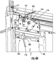
- FIG. 4A is a schematic illustration of the elevator landing door lock assembly 410 as installed on an interior (i.e., elevator shaft) side of a landing door 431, without the presence of an elevator car aligned therewith.
- FIG. 4B is a schematic illustration of the landing door 431 with an elevator car aligned therewith, the elevator car having an elevator car door coupling 400.
- FIG. 4C is a schematic illustration showing partial actuation of the elevator landing door lock assembly 410 and interaction with the elevator car door coupling 400.
- FIG. 4D is a schematic illustration showing the elevator car door coupling 400 in an unlocked state as actuated by the elevator landing door lock assembly 410.
- the elevator car is not shown for simplicity and clarity, but the elevator car door coupling 400 is mounted to or otherwise attached/connected to an exterior of an elevator car (and particularly exterior of an elevator car door).
- the landing door 431 (or a panel thereof) has the elevator landing door lock assembly 410 attached thereto.
- the elevator landing door lock assembly 410 provides a keyway that is accessible from the landing, as will be appreciated by those of skill in the art.
- the landing door 431 is equipped with a landing door coupling 412.
- the landing door coupling 412 includes a landing door coupling support 414 having two rollers 416.
- the rollers 416 are positioned such that an elevator car can move freely within an elevator shaft without interfering with parts of the elevator car (e.g., an elevator car door coupling, etc.).
- the elevator landing door lock assembly 410 includes a disengageable link 418, illustrated in FIGS. 4A-4D as an actuator arm.
- the disengageable link 418 is fixedly connected to a lock 420 which includes keyway.
- the disengageable link 418 is operably connected to the lock 420 (or a portion thereof, such as a keyway or cylinder) such that rotation of the lock 420 or a portion thereof (i.e., rotation of a key within the lock which turns a cylinder) urges the disengageable link 418 to also rotate.
- the disengageable link 418 is a lever arm that extends from the lock 420. Without an elevator car present, the elevator landing door lock assembly 410 cannot interact with either an elevator car door coupling or the landing door coupling 412, and thus the landings door 431 cannot be opened.
- the landing door coupling 412 To enable opening of the landing door 431, the landing door coupling 412 must be actuated through interaction with an elevator car door coupling. Specifically, the rollers 416 must be engaged to thus enable unlocking and opening of the landing door 431.
- FIG. 4B a portion of an elevator car is positioned in alignment with the landing door coupling 412.
- the illustrated portion of the elevator car is an elevator car door coupling 400.
- the elevator car door coupling 400 includes a first vane 402 and a second vane 404.
- the elevator car door coupling 400 aligns with the landing door coupling 412 and the first and second vanes 402, 404 are positioned between the rollers 416 of the landing door coupling 412.
- the elevator car door coupling 400 In normal operation, the elevator car door coupling 400 will be electrically or otherwise operated to spread the vanes 402, 404 into engagement with the rollers 416, which enables opening of both the elevator car door and the landing door 431. However, when power is not provided, manual operation of the opening mechanism is required (e.g., in emergency situations). Manual operation requires manual actuation of the elevator car door coupling 400 such that the vanes 402, 404 will engage with the rollers 416, which will enable opening of the landing door 431 and the elevator car door. In prior configurations, operation of a key could unlock the landing door without the presence of an elevator car (as noted above).
- the disengageable link 418 is rotated such that the disengageable link 418 contacts one of the vanes 402, 404. Such contact is possible because the elevator car door coupling 400 is aligned with the landing door coupling 412. If the elevator car door coupling 400 was not present, rotation of the disengageable link 418 by operation of the lock 420 would not achieve any result (i.e., the disengageable link 418 would merely rotate but not contact anything).
- the elevator car door coupling 400 can be operated. That is, as shown in FIG. 4D , the disengageable link 418 can push on or otherwise urge the second vane 404 away from the first vane 402 such that the vanes 402, 404 contact the rollers 416.
- the vanes 402, 404 contact and engage with the rollers 416, the landing door 431 and the elevator car door are unlocked and manual opening of the doors is enabled.
- embodiments of the present disclosure are provided to establish a temporary or transient link between a landing door locking device and an unlocking device for the landing door. Accordingly, embodiments provided herein break or separate the link such that the link is only established when an elevator car is present at the respective landing door. This is achieved by placing the missing link of the locking device on the elevator car. As such, it becomes necessary to have the elevator car in the door zone (i.e., at the landing) to operate the unlocking device of the landing door.
- embodiments described herein provide elevator landing door lock assemblies that are configured to prevent opening of landing doors when no elevator car is present at the landing doors.
Description
- The subject matter disclosed herein generally relates to elevator systems and, more particularly, to systems for unlocking elevator landing doors.
- In a typical elevator or lift installation, a vertically moving elevator car can be positioned at one of a number of landing floors so as to align elevator car doors with corresponding landing doors located at one of the landings. Modern installations typically have one or more horizontally sliding elevator car doors and at least one sliding landing door located at each of the landing floors, all of which remain closed during movement of the elevator car.
- Upon arrival of the elevator car at a landing, a door opening mechanism is activated which drives the elevator car door horizontally to open the elevator car door. In typical installations, a door coupling employing one or more vanes projecting from the surface of the elevator car door in the direction of the adjacent landing door engages various structures of the landing door. For example vanes, rollers, or other protrusions can be configured to project from the landing door to enable engagement and/or coupling between the elevator car door and the landing door. Through the engagement and/or coupling, the elevator car door drives the landing door horizontally open. As such, passengers can enter or exit the elevator car.
US 1 950 150 A shows a hatchway door unlocking and opening mechanism on a landing door, according to the preamble of claim 1. The mechanism comprises an aperture through which a key is inserted to move a member towards a car door cam. The car door cam is then brought into contact with a roller on a bell crank. The mechanism opens the hatchway door only when an elevator car is opposite the floor for which the hatchway door is provided. - Elevator codes and regulations may require that the landing doors remain locked and fastened securely to prevent opening and thereby prevent unauthorized opening unless an elevator car is positioned directly adjacent the landing (e.g., engagement/coupling of doors). Further, elevator car doors may be required to remain latched against manual movement unless the elevator car is positioned at a landing, and the doors are aligned (e.g., detected alignment) and/or engaged/coupled. Various mechanisms and systems have been employed to secure and unsecure landing and elevator car doors. It may be advantageous to provide secure mechanisms to enable locking/unlocking the elevator system doors while also providing safety measures to prevent opening under unauthorized and/or unsafe opening conditions (e.g., elevator car not present at landing).
- According to some embodiments, elevator landing door lock assemblies are provided. The elevator landing door locks include a lock having a keyway accessible from a landing of an elevator system, the lock operable to lock and unlock a landing door and a disengageable link operably connected to the lock and configured to prevent unlocking of the landing door when the disengageable link is not engaged. When an elevator car is aligned with the landing door, the disengageble link is engaged and completed such that the lock is operable to unlock and open the landing door, and when an elevator car is not aligned with the landing door, the lock is not operable.
- In addition to one or more of the features described herein, or as an alternative, further embodiments of the elevator landing door lock assemblies may include that the disengageable link is an actuator arm operably connected to the lock such that rotation of a key within the keyway actuates the actuator arm.
- In addition to one or more of the features described herein, or as an alternative, further embodiments of the elevator landing door lock assemblies may include that actuation of the actuator arm urges a portion of an elevator car door coupling into contact with a landing door coupling to enable opening of the landing door.
- In addition to one or more of the features described herein, or as an alternative, further embodiments of the elevator landing door lock assemblies may include that the actuator arm is a lever that contacts a vane of the elevator car door coupling.
- In addition to one or more of the features described herein, or as an alternative, further embodiments of the elevator landing door lock assemblies may include a landing door coupling positioned away from the lock and configured to operate through contact from a portion of the elevator car door coupling.
- In addition to one or more of the features described herein, or as an alternative, further embodiments of the elevator landing door lock assemblies may include that the landing door coupling comprises one or more rollers configured to engage with the portion of the elevator car door coupling.
- In addition to one or more of the features described herein, or as an alternative, further embodiments of the elevator landing door lock assemblies may include that the actuation of the actuator arm comprises a rotational movement.
- According to some embodiments, elevator systems are provided. The elevator systems include an elevator car located within an elevator shaft, a landing having a landing door openable on the elevator shaft, and a landing door lock assembly. The landing door lock assembly includes a lock having a keyway accessible from the landing and located within the elevator shaft, and a disengageable link operably connected to the lock and configured to prevent unlocking of the landing door when the disengageable link is not engaged, wherein, when an elevator car is aligned with the landing door, the disengageble link is engaged and completed such that the lock is operable to unlock and open the landing door, and wherein, when an elevator car is not aligned with the landing door, the lock is not operable.
- In addition to one or more of the features described herein, or as an alternative, further embodiments of the elevator systems may include that the disengageable link is an actuator arm operably connected to the lock such that rotation of a key within the keyway actuates the actuator arm.
- In addition to one or more of the features described herein, or as an alternative, further embodiments of the elevator systems may include that actuation of the actuator arm urges a portion of an elevator car door coupling into contact with a landing door coupling to enable opening of the landing door.
- In addition to one or more of the features described herein, or as an alternative, further embodiments of the elevator systems may include that the actuator arm is a lever that contacts a vane of the elevator car door coupling.
- In addition to one or more of the features described herein, or as an alternative, further embodiments of the elevator systems may include a landing door coupling positioned within the elevator shaft and away from the lock, the landing door coupling configured to operate through contact from a portion of the elevator car door coupling.
- In addition to one or more of the features described herein, or as an alternative, further embodiments of the elevator systems may include that the landing door coupling comprises one or more rollers configured to engage with the portion of the elevator car door coupling.
- In addition to one or more of the features described herein, or as an alternative, further embodiments of the elevator systems may include that the actuation of the actuator arm comprises a rotational movement.
- Technical effects of embodiments of the present disclosure include systems and devices for preventing opening elevator landing door(s) unless an elevator car is located at the landing. Further technical effects include a lock and a disengageable link, such as an actuator arm, configured such that the disengageable link engages with a portion of an elevator car door coupling to enable opening of the elevator car door and a respective landing door.
- The foregoing features and elements may be combined in various combinations without exclusivity, unless expressly indicated otherwise. These features and elements as well as the operation thereof will become more apparent in light of the following description and the accompanying drawings. It should be understood, however, that the following description and drawings are intended to be illustrative and explanatory in nature and non-limiting.
- The invention is defined by the combination of features of claim 1. The foregoing and other features, and advantages of the present disclosure are apparent from the following detailed description taken in conjunction with the accompanying drawings in which:
-
FIG. 1 is a schematic illustration of an elevator system that may employ various embodiments of the present disclosure; -
FIG. 2A is a schematic, partial plan view of an elevator car in an elevator shaft with elevator car doors and landing doors in a closed position; -
FIG. 2B is a schematic illustration of the elevator car and landing doors ofFIG. 2A shown in an open position; -
FIG. 3A is a schematic illustration of an elevator car door coupling shown in a closed state; -
FIG. 3B is a schematic illustration of the elevator car door coupling ofFIG. 3A in an open state; -
FIG. 4A is a schematic illustration of an elevator landing door lock assembly in accordance with an embodiment of the present disclosure, with no elevator car present; -
FIG. 4B is a schematic illustration showing a portion of an elevator car aligned with a landing and illustrating a first position of the elevator landing door lock assembly ofFIG. 4A ; -
FIG. 4C is a schematic illustration illustrating a second position of the elevator landing door lock assembly ofFIG. 4A engaged with a portion of an elevator car door coupling; and -
FIG. 4D is a schematic illustration illustrating a third position of the elevator landing door lock assembly ofFIG. 4A engaged and urging the elevator car door coupling into an open position. - As shown and described herein, various features of the disclosure will be presented. Various embodiments may have the same or similar features and thus the same or similar features may be labeled with the same reference numeral, but preceded by a different first number indicating the figure in which the feature is shown. Thus, for example, element "a" that is shown in FIG. X may be labeled "Xa" and a similar feature in FIG. Z may be labeled "Za." Although similar reference numbers may be used in a generic sense, various embodiments will be described and various features may include changes, alterations, modifications, etc. as will be appreciated by those of skill in the art, whether explicitly described or otherwise would be appreciated by those of skill in the art.
-
FIG. 1 is a perspective view of anelevator system 101 including anelevator car 103, acounterweight 105, one or moreload bearing members 107, aguide rail 109, amachine 111, aposition encoder 113, and anelevator controller 115. Theelevator car 103 andcounterweight 105 are connected to each other by theload bearing members 107. Theload bearing members 107 may be, for example, ropes, steel cables, and/or coated-steel belts. Thecounterweight 105 is configured to balance a load of theelevator car 103 and is configured to facilitate movement of theelevator car 103 concurrently and in an opposite direction with respect to thecounterweight 105 within anelevator shaft 117 and along theguide rail 109. - The
load bearing members 107 engage themachine 111, which is part of an overhead structure of theelevator system 101. Themachine 111 is configured to control movement between theelevator car 103 and thecounterweight 105. The position encoder 113 may be mounted on an upper sheave of a speed-governor system 119 and may be configured to provide position signals related to a position of theelevator car 103 within theelevator shaft 117. In other embodiments, theposition encoder 113 may be directly mounted to a moving component of themachine 111, or may be located in other positions and/or configurations as known in the art. - The
elevator controller 115 is located, as shown, in acontroller room 121 of theelevator shaft 117 and is configured to control the operation of theelevator system 101, and particularly theelevator car 103. For example, theelevator controller 115 may provide drive signals to themachine 111 to control the acceleration, deceleration, leveling, stopping, etc. of theelevator car 103. Theelevator controller 115 may also be configured to receive position signals from theposition encoder 113. When moving up or down within theelevator shaft 117 alongguide rail 109, theelevator car 103 may stop at one ormore landings 125 as controlled by theelevator controller 115. Although shown in acontroller room 121, those of skill in the art will appreciate that theelevator controller 115 can be located and/or configured in other locations or positions within theelevator system 101. In some embodiments, theelevator controller 115 can be configured to control features within theelevator car 103, including, but not limited to, lighting, display screens, music, spoken audio words, etc. - The
machine 111 may include a motor or similar driving mechanism and an optional braking system. In accordance with embodiments of the disclosure, themachine 111 is configured to include an electrically driven motor. The power supply for the motor may be any power source, including a power grid, which, in combination with other components, is supplied to the motor. Although shown and described with a rope-based load bearing system, elevator systems that employ other methods and mechanisms of moving an elevator car within an elevator shaft may employ embodiments of the present disclosure.FIG. 1 is merely a non-limiting example presented for illustrative and explanatory purposes. - Turning to
FIGS. 2A-2B , partial plan view illustrations of operation of elevator doors of an elevator system are shown. InFIGS. 2A-2B , anelevator car 203 is located within anelevator shaft 217 and positioned within theelevator shaft 217 in alignment with anopening 227 at alanding 225. As shown,elevator car doors 229 are aligned with landingdoors 231 at thelanding 225. Theelevator car doors 229 are operated and actuated by adoor operator 233. Thedoor operator 233 can be in operable communication with a controller (e.g., elevator controller 115). Thedoor operator 233, in the present embodiment, is shown located atop theelevator car 203, although other locations of thedoor operator 233 can be employed without departing from the scope of the present disclosure. Thedoor operator 233 includes adrive mechanism 235, such as a belt or chain operably driven by a motor or other device.FIG. 2A illustrates theelevator car doors 229 and thelanding doors 231 in a closed position.FIG. 2B illustrates theelevator car doors 229 and thelanding doors 231 in a partially opened position. - As shown in
FIGS. 2A-2B , eachelevator car door 229 is coupled to arespective landing door 231 by an elevatorcar door coupling 239 that is part of or mounted to the respectiveelevator car door 229. Each elevatorcar door coupling 239 engages with and couples to a correspondinglanding door coupling 237. As will be appreciated by those of skill in the art, thelanding door couplings 237 can be configured as protrusions or other structures that are designed to engage with the elevatorcar door couplings 239. Thelanding door couplings 237, for example, can be raised bosses, bumpers, rods, rollers, etc., that are configured to act upon and move therespective landing door 231 concurrently with operation of theelevator car doors 229 through engagement of thecouplings car door coupling 239 firmly/tightly grip a respective thelanding door coupling 237 when theelevator car door 229 and thelanding door 231 are operated (e.g., opened/closed simultaneously). Furthermore, it is desirable that the elevatorcar door coupling 239 completely release the respectivelanding door coupling 237 and maintain sufficient running clearance as theelevator car 203 moves vertically through theelevator shaft 217. The elevatorcar door coupling 239 is configured to operate only when it has been determined that theelevator car 203 is positioned within a landing door zone, adjacent arespective landing door 231 at alanding 225. - During emergency situations, such as power loss or similar events, it may be necessary for rescue or emergency personnel to open the elevator landing doors to aid in a rescue operation. Accordingly, it is possible to manually unlock the landing door lock using a mechanism actuated by a triangular key, as known in the art. However, this unlocking operation is possible regardless of the position of the elevator car. That is, in some instances, the elevator landing doors may be openable when an elevator car is not present and adjacent the elevator landing doors. Such situation may be dangerous and thus preventing such access and operation of the landing doors when the car is not present may be advantageous.
- Accordingly, embodiments provided herein are directed to apparatuses, systems, and methods directed to elevator landing door locking/unlocking mechanisms that are designed to enable opening of landing doors only when an elevator car is present at the particular landing. That is, embodiments provided herein are directed to landing door locking mechanisms that do not enable opening of the landing doors unless there is an elevator car present at the landing doors. In the event of an emergency, with such mechanisms, the emergency personnel can move an elevator car to a desired landing and then unlock and open the elevator doors (landing doors and elevator car doors).
- Turning now to
FIGS. 3A-3B , schematic illustrations of an elevatorcar door coupling 300 are shown, withFIG. 3A illustrating a closed position andFIG. 3B illustrating an open position. The elevatorcar door coupling 300 is mounted to an exterior surface of an elevator car door and travels with the elevator car as the elevator car moves within an elevator shaft. The elevatorcar door coupling 300 is engageable with a landing door coupling (not shown), and, when engaged, enables opening of the elevator car doors and the landing doors (e.g., as shown inFIGS. 2A-2B ). When the elevator car is traveling within the elevator shaft, the elevatorcar door coupling 300 is in the closed position (FIG. 3A ) and is configured to prevent contact between the elevatorcar door coupling 300 and landing door couplings located at each landing. -
FIGS. 3A-3B illustrate the elevatorcar door coupling 300 as it would appear viewed in elevation when a corresponding elevator car door is in the fully closed position. The elevatorcar door coupling 300, as shown, includes afirst vane 302 and asecond vane 304. The first andsecond vanes second vanes support 306 mounted to the elevator car. The first andsecond vanes links 308. - When disposed in the orientation as shown in
FIG. 3A (closed position), the elevator car door coupling 300 permits vertical movement of the elevator car within the elevator shaft without interference with the landing door couplings. That is, the first andsecond vanes - In contrast,
FIG. 3B illustrates the elevatorcar door coupling 300 as it appears during normal opening operation of an elevator car door when positioned relative to a landing door (e.g., coupled to a landing door coupling). As can be seen inFIG. 3B (as compared toFIG. 3A ), the first andsecond vanes - In traditional elevator car/landing door coupling configurations, it may be possible to manually unlock the landing door coupling using a mechanism actuated by a triangular key that is inserted from the landing. Such traditional coupling configurations may be unlocked even if the car is not present at the particular landing. That is, the landing doors can be unlocked, opened, and access can be granted to the elevator shaft, even if an elevator car is not present at the landing. Such access can be dangerous, and thus preventing such access is desirable. However, enabling emergency personnel to open the landing doors, such as during rescue operations, is also desirable.
- Accordingly, embodiments provided herein are directed to landing door unlocking devices that prevent opening of the landing doors when an elevator car is not present, and enable unlocking only when an elevator car is present. That is, features provided in accordance with embodiments of the present disclosure are directed to structures that ensure an elevator car is present to enable operation of the unlocking mechanism.
- For example, turning now to
FIGS. 4A-4D , schematic illustrations of an elevator landingdoor lock assembly 410 in accordance with an embodiment of the present disclosure are shown. The elevator landingdoor lock assembly 410 is a locking mechanism that has a keyway accessible from a landing. The keyway enables insertion of a key, such as a triangular key, into the elevator landingdoor lock assembly 410 and actuation of the elevator landingdoor lock assembly 410. Actuation of the elevator landingdoor lock assembly 410 enables unlocking of alanding door 431 which then enables opening of thelanding door 431. -
FIG. 4A is a schematic illustration of the elevator landingdoor lock assembly 410 as installed on an interior (i.e., elevator shaft) side of alanding door 431, without the presence of an elevator car aligned therewith.FIG. 4B is a schematic illustration of thelanding door 431 with an elevator car aligned therewith, the elevator car having an elevatorcar door coupling 400.FIG. 4C is a schematic illustration showing partial actuation of the elevator landingdoor lock assembly 410 and interaction with the elevatorcar door coupling 400.FIG. 4D is a schematic illustration showing the elevatorcar door coupling 400 in an unlocked state as actuated by the elevator landingdoor lock assembly 410. InFIGS. 4B-4D , the elevator car is not shown for simplicity and clarity, but the elevatorcar door coupling 400 is mounted to or otherwise attached/connected to an exterior of an elevator car (and particularly exterior of an elevator car door). - With reference to
FIG. 4A , the landing door 431 (or a panel thereof) has the elevator landingdoor lock assembly 410 attached thereto. The elevator landingdoor lock assembly 410 provides a keyway that is accessible from the landing, as will be appreciated by those of skill in the art. Also, shown inFIG. 4A , thelanding door 431 is equipped with alanding door coupling 412. Thelanding door coupling 412, as shown, includes a landingdoor coupling support 414 having tworollers 416. Therollers 416 are positioned such that an elevator car can move freely within an elevator shaft without interfering with parts of the elevator car (e.g., an elevator car door coupling, etc.). - As shown, the elevator landing
door lock assembly 410 includes adisengageable link 418, illustrated inFIGS. 4A-4D as an actuator arm. The disengageable link 418 is fixedly connected to alock 420 which includes keyway. The disengageable link 418 is operably connected to the lock 420 (or a portion thereof, such as a keyway or cylinder) such that rotation of thelock 420 or a portion thereof (i.e., rotation of a key within the lock which turns a cylinder) urges the disengageable link 418 to also rotate. As shown, in the present embodiment, the disengageable link 418 is a lever arm that extends from thelock 420. Without an elevator car present, the elevator landingdoor lock assembly 410 cannot interact with either an elevator car door coupling or thelanding door coupling 412, and thus thelandings door 431 cannot be opened. - To enable opening of the
landing door 431, thelanding door coupling 412 must be actuated through interaction with an elevator car door coupling. Specifically, therollers 416 must be engaged to thus enable unlocking and opening of thelanding door 431. - Turning now to
FIG. 4B , a portion of an elevator car is positioned in alignment with thelanding door coupling 412. As shown, the illustrated portion of the elevator car is an elevatorcar door coupling 400. As described above and shown inFIG. 4B , the elevatorcar door coupling 400 includes afirst vane 402 and asecond vane 404. When the elevator car door (not shown) is aligned with thelanding door 431, the elevatorcar door coupling 400 aligns with thelanding door coupling 412 and the first andsecond vanes rollers 416 of thelanding door coupling 412. - In normal operation, the elevator
car door coupling 400 will be electrically or otherwise operated to spread thevanes rollers 416, which enables opening of both the elevator car door and thelanding door 431. However, when power is not provided, manual operation of the opening mechanism is required (e.g., in emergency situations). Manual operation requires manual actuation of the elevatorcar door coupling 400 such that thevanes rollers 416, which will enable opening of thelanding door 431 and the elevator car door. In prior configurations, operation of a key could unlock the landing door without the presence of an elevator car (as noted above). - As shown in
FIG. 4C , the disengageable link 418 is rotated such that the disengageable link 418 contacts one of thevanes car door coupling 400 is aligned with thelanding door coupling 412. If the elevatorcar door coupling 400 was not present, rotation of the disengageable link 418 by operation of thelock 420 would not achieve any result (i.e., the disengageable link 418 would merely rotate but not contact anything). - However, when contact is achieved between the disengageable link 418 and a portion of the elevator car door coupling 400 (e.g., one of the
vanes 402, 404), the elevatorcar door coupling 400 can be operated. That is, as shown inFIG. 4D , the disengageable link 418 can push on or otherwise urge thesecond vane 404 away from thefirst vane 402 such that thevanes rollers 416. When thevanes rollers 416, thelanding door 431 and the elevator car door are unlocked and manual opening of the doors is enabled. - Although described herein with respect to a specific embodiment and configurations thereof, those of skill in the art will appreciate that alternative mechanisms, structures, features, processes, etc. can be employed to achieve similar operation and features. For example, generally speaking, embodiments of the present disclosure are provided to establish a temporary or transient link between a landing door locking device and an unlocking device for the landing door. Accordingly, embodiments provided herein break or separate the link such that the link is only established when an elevator car is present at the respective landing door. This is achieved by placing the missing link of the locking device on the elevator car. As such, it becomes necessary to have the elevator car in the door zone (i.e., at the landing) to operate the unlocking device of the landing door.
- Advantageously, embodiments described herein provide elevator landing door lock assemblies that are configured to prevent opening of landing doors when no elevator car is present at the landing doors.
- While the present disclosure has been described in detail in connection with only a limited number of embodiments, it should be readily understood that the present disclosure is not limited to such disclosed embodiments.
- Accordingly, the present invention is not to be seen as limited by the foregoing description, but is only limited by the scope of the appended claims.
Claims (7)
- An elevator system (101) comprising:an elevator car (103) located within an elevator shaft (117), the elevator car (103) having an elevator car door coupling (400);a landing having a landing door (431) openable on the elevator shaft (117), the landing door (431) comprising a landing door coupling (412) having one or more rollers (416); andan elevator landing door lock assembly (410) comprising:a lock (420) having a keyway accessible from a landing of an elevator system (101), the lock (420) operable to lock and unlock the landing door (431); anda disengageable link (418) operably connected to the lock (420) and configured to prevent unlocking of the landing door (431) when the disengageable link (418) is not engaged,wherein, when the elevator car (103) is aligned with the landing door (431), the disengageble link (418) is engaged and completed such that the lock (420) is operable to unlock and open the landing door (431), andwherein, when the elevator car (103) is not aligned with the landing door (431), the lock (420) is not operable,characterised in thatthe elevator car door coupling (400) comprises a first vane (402) and a second vane (404); andthe disengageable link (418) is configured to urge the second vane (404) away from the first vane (402) such that the vanes (402, 404) contact the one or more rollers (416).
- The elevator system (101) of claim 1, wherein the disengageable link (418) is an actuator arm operably connected to the lock (420) such that rotation of a key within the keyway actuates the actuator arm.
- The elevator system (101) of claim 2, wherein actuation of the actuator arm urges a portion of an elevator car door coupling (400) into contact with a landing door coupling (412) to enable opening of the landing door (431).
- The elevator system (101) of any of claims 2-3, wherein the actuator arm is a lever that contacts the first vane (402) or the second vane (404) of the elevator car door coupling (400).
- The elevator system (101) of any of the preceding claims, wherein the landing door coupling (412) is positioned away from the lock (420) and configured to operate through contact from a portion of the elevator car door coupling (400).
- The elevator system (101) of any of claims 2-5, wherein the actuation of the actuator arm comprises a rotational movement.
- The elevator system (101) of any of claims 1 to 6, wherein the lock (420) of the landing door lock assembly (410) is located within the elevator shaft (117).
Priority Applications (3)
| Application Number | Priority Date | Filing Date | Title |
|---|---|---|---|
| EP16306856.2A EP3342743B1 (en) | 2016-12-30 | 2016-12-30 | Elevator landing door unlocking system |
| US15/832,934 US10822201B2 (en) | 2016-12-30 | 2017-12-06 | Elevator landing door unlocking system |
| CN201711472848.4A CN108263937B (en) | 2016-12-30 | 2017-12-29 | Elevator landing door unlocking system |
Applications Claiming Priority (1)
| Application Number | Priority Date | Filing Date | Title |
|---|---|---|---|
| EP16306856.2A EP3342743B1 (en) | 2016-12-30 | 2016-12-30 | Elevator landing door unlocking system |
Publications (2)
| Publication Number | Publication Date |
|---|---|
| EP3342743A1 EP3342743A1 (en) | 2018-07-04 |
| EP3342743B1 true EP3342743B1 (en) | 2022-11-30 |
Family
ID=57821786
Family Applications (1)
| Application Number | Title | Priority Date | Filing Date |
|---|---|---|---|
| EP16306856.2A Active EP3342743B1 (en) | 2016-12-30 | 2016-12-30 | Elevator landing door unlocking system |
Country Status (3)
| Country | Link |
|---|---|
| US (1) | US10822201B2 (en) |
| EP (1) | EP3342743B1 (en) |
| CN (1) | CN108263937B (en) |
Families Citing this family (4)
| Publication number | Priority date | Publication date | Assignee | Title |
|---|---|---|---|---|
| US11254542B2 (en) | 2018-08-20 | 2022-02-22 | Otis Elevator Company | Car door interlock |
| US11390487B2 (en) * | 2018-08-21 | 2022-07-19 | Otis Elevator Company | Automated elevator safety chain diagnosis |
| CN112638813B (en) * | 2018-09-06 | 2022-07-01 | 三菱电机株式会社 | Elevator car door device |
| US11247872B2 (en) | 2018-10-17 | 2022-02-15 | Otis Elevator Company | Elevator car door interlock |
Family Cites Families (21)
| Publication number | Priority date | Publication date | Assignee | Title |
|---|---|---|---|---|
| US1950150A (en) * | 1933-10-11 | 1934-03-06 | Otis Elevator Co | Elevator door mechanism |
| US4483420A (en) * | 1982-07-01 | 1984-11-20 | Byrne Francis J | Elevator door interlocking apparatus |
| ATE75458T1 (en) | 1988-03-18 | 1992-05-15 | Inventio Ag | DOOR OPERATING DEVICE WITH LOCKING MECHANISM FOR ELEVATORS. |
| BR9101160A (en) | 1991-03-25 | 1992-11-17 | Elevadores Otis Ltda | SECURITY SYSTEM FOR LOCKING AN ELEVATOR HANGING DOOR |
| JPH072473A (en) | 1991-08-05 | 1995-01-06 | Hitachi Ltd | Manually unlocking method for elevator door |
| JPH107353A (en) * | 1996-06-19 | 1998-01-13 | Hitachi Ltd | Elevator landing door locking device |
| EP1400480A1 (en) | 2002-09-18 | 2004-03-24 | Inventio Ag | Door coupler with locking device |
| DE10301325B4 (en) | 2003-01-15 | 2012-04-12 | Hans & Jos. Kronenberg Gmbh | Door lock with emergency release |
| ZA200406978B (en) * | 2003-09-17 | 2005-06-20 | Inventio Ag | Device for connecting a cage door with a shaft door and for locking and unlocking the doors, a device for emergency unlocking of a cage door and a method for emergency unlocking of a cage door. |
| CN2672012Y (en) | 2004-01-16 | 2005-01-19 | 张广兴 | Novel anti-fall, anti-shear lift safety door lock |
| WO2005090218A1 (en) | 2004-03-23 | 2005-09-29 | Mitsubishi Denki Kabushiki Kaisha | Unlocking device of elevator landing door and method of modifying the device |
| JP4858172B2 (en) * | 2005-01-04 | 2012-01-18 | 三菱電機株式会社 | Elevator landing door equipment |
| CN101128387B (en) | 2005-02-03 | 2010-09-15 | 奥蒂斯电梯公司 | Safety lock for elevator landing door |
| EP2035315B1 (en) | 2006-06-30 | 2012-09-05 | Otis Elevator Company | Elevator having a shallow pit and/or a low overhead |
| CN201864426U (en) * | 2010-06-21 | 2011-06-15 | 深圳市特种设备安全检验研究院 | Door lock for landing door of lift |
| CN202464974U (en) | 2012-01-10 | 2012-10-03 | 上海三菱电梯有限公司 | Triangle key safety unlocking device of elevator landing door |
| FI125118B (en) | 2013-01-07 | 2015-06-15 | Kone Corp | Elevator |
| CN103612966B (en) | 2013-12-06 | 2015-07-01 | 日立电梯(中国)有限公司 | Elevator car door lock manual unlocking device |
| EP3230194A1 (en) | 2014-12-12 | 2017-10-18 | Otis Elevator Company | Hoistway landing door locking system and method of controlling access to an elevator shaft |
| CN204549768U (en) | 2015-04-01 | 2015-08-12 | 三菱电机上海机电电梯有限公司 | Elevator door emergency unlocking device |
| CN205367429U (en) | 2016-02-25 | 2016-07-06 | 上海现代电梯制造有限公司 | Elevator layer every lock linkage structure |
-
2016
- 2016-12-30 EP EP16306856.2A patent/EP3342743B1/en active Active
-
2017
- 2017-12-06 US US15/832,934 patent/US10822201B2/en active Active
- 2017-12-29 CN CN201711472848.4A patent/CN108263937B/en active Active
Also Published As
| Publication number | Publication date |
|---|---|
| US20180186606A1 (en) | 2018-07-05 |
| CN108263937A (en) | 2018-07-10 |
| CN108263937B (en) | 2021-11-05 |
| EP3342743A1 (en) | 2018-07-04 |
| US10822201B2 (en) | 2020-11-03 |
Similar Documents
| Publication | Publication Date | Title |
|---|---|---|
| US11795033B2 (en) | Elevator car door interlock | |
| EP3636577B1 (en) | Elevator landing door unlocking system | |
| US10822201B2 (en) | Elevator landing door unlocking system | |
| JP5940220B2 (en) | Elevator car door lock device | |
| US10710843B2 (en) | Car door interlock with sill lock | |
| US6446759B1 (en) | Door coupler and latch system for elevator car and landing doors | |
| WO2006097997A1 (en) | Interlock device for car door of elevator | |
| US11358837B2 (en) | Elevator car ceiling access system | |
| US11124385B2 (en) | Elevator access systems for elevators | |
| EP3360837B1 (en) | Maintenance access system for elevators | |
| US11235951B2 (en) | Openable elevator car wall panels | |
| US11091351B2 (en) | Elevator lintel door lock safety devices | |
| US11542119B2 (en) | Elevator access systems for elevators | |
| CN113998570B (en) | Elevator device | |
| JP6881521B2 (en) | Elevator door device | |
| JP2013142016A (en) | Car door device for elevator | |
| KR20020093535A (en) | Apparatus locking car door of elevator | |
| KR20020093533A (en) | Apparatus to locking car door of elevator |
Legal Events
| Date | Code | Title | Description |
|---|---|---|---|
| PUAI | Public reference made under article 153(3) epc to a published international application that has entered the european phase |
Free format text: ORIGINAL CODE: 0009012 |
|
| STAA | Information on the status of an ep patent application or granted ep patent |
Free format text: STATUS: THE APPLICATION HAS BEEN PUBLISHED |
|
| AK | Designated contracting states |
Kind code of ref document: A1 Designated state(s): AL AT BE BG CH CY CZ DE DK EE ES FI FR GB GR HR HU IE IS IT LI LT LU LV MC MK MT NL NO PL PT RO RS SE SI SK SM TR |
|
| AX | Request for extension of the european patent |
Extension state: BA ME |
|
| STAA | Information on the status of an ep patent application or granted ep patent |
Free format text: STATUS: REQUEST FOR EXAMINATION WAS MADE |
|
| 17P | Request for examination filed |
Effective date: 20190103 |
|
| RBV | Designated contracting states (corrected) |
Designated state(s): AL AT BE BG CH CY CZ DE DK EE ES FI FR GB GR HR HU IE IS IT LI LT LU LV MC MK MT NL NO PL PT RO RS SE SI SK SM TR |
|
| STAA | Information on the status of an ep patent application or granted ep patent |
Free format text: STATUS: REQUEST FOR EXAMINATION WAS MADE |
|
| STAA | Information on the status of an ep patent application or granted ep patent |
Free format text: STATUS: EXAMINATION IS IN PROGRESS |
|
| 17Q | First examination report despatched |
Effective date: 20210212 |
|
| STAA | Information on the status of an ep patent application or granted ep patent |
Free format text: STATUS: EXAMINATION IS IN PROGRESS |
|
| GRAP | Despatch of communication of intention to grant a patent |
Free format text: ORIGINAL CODE: EPIDOSNIGR1 |
|
| STAA | Information on the status of an ep patent application or granted ep patent |
Free format text: STATUS: GRANT OF PATENT IS INTENDED |
|
| INTG | Intention to grant announced |
Effective date: 20220705 |
|
| GRAS | Grant fee paid |
Free format text: ORIGINAL CODE: EPIDOSNIGR3 |
|
| GRAA | (expected) grant |
Free format text: ORIGINAL CODE: 0009210 |
|
| STAA | Information on the status of an ep patent application or granted ep patent |
Free format text: STATUS: THE PATENT HAS BEEN GRANTED |
|
| AK | Designated contracting states |
Kind code of ref document: B1 Designated state(s): AL AT BE BG CH CY CZ DE DK EE ES FI FR GB GR HR HU IE IS IT LI LT LU LV MC MK MT NL NO PL PT RO RS SE SI SK SM TR |
|
| REG | Reference to a national code |
Ref country code: CH Ref legal event code: EP Ref country code: GB Ref legal event code: FG4D |
|
| REG | Reference to a national code |
Ref country code: AT Ref legal event code: REF Ref document number: 1534557 Country of ref document: AT Kind code of ref document: T Effective date: 20221215 Ref country code: DE Ref legal event code: R096 Ref document number: 602016076582 Country of ref document: DE |
|
| REG | Reference to a national code |
Ref country code: IE Ref legal event code: FG4D |
|
| REG | Reference to a national code |
Ref country code: LT Ref legal event code: MG9D |
|
| REG | Reference to a national code |
Ref country code: NL Ref legal event code: MP Effective date: 20221130 |
|
| PG25 | Lapsed in a contracting state [announced via postgrant information from national office to epo] |
Ref country code: SE Free format text: LAPSE BECAUSE OF FAILURE TO SUBMIT A TRANSLATION OF THE DESCRIPTION OR TO PAY THE FEE WITHIN THE PRESCRIBED TIME-LIMIT Effective date: 20221130 Ref country code: PT Free format text: LAPSE BECAUSE OF FAILURE TO SUBMIT A TRANSLATION OF THE DESCRIPTION OR TO PAY THE FEE WITHIN THE PRESCRIBED TIME-LIMIT Effective date: 20230331 Ref country code: NO Free format text: LAPSE BECAUSE OF FAILURE TO SUBMIT A TRANSLATION OF THE DESCRIPTION OR TO PAY THE FEE WITHIN THE PRESCRIBED TIME-LIMIT Effective date: 20230228 Ref country code: LT Free format text: LAPSE BECAUSE OF FAILURE TO SUBMIT A TRANSLATION OF THE DESCRIPTION OR TO PAY THE FEE WITHIN THE PRESCRIBED TIME-LIMIT Effective date: 20221130 Ref country code: FI Free format text: LAPSE BECAUSE OF FAILURE TO SUBMIT A TRANSLATION OF THE DESCRIPTION OR TO PAY THE FEE WITHIN THE PRESCRIBED TIME-LIMIT Effective date: 20221130 Ref country code: ES Free format text: LAPSE BECAUSE OF FAILURE TO SUBMIT A TRANSLATION OF THE DESCRIPTION OR TO PAY THE FEE WITHIN THE PRESCRIBED TIME-LIMIT Effective date: 20221130 |
|
| REG | Reference to a national code |
Ref country code: AT Ref legal event code: MK05 Ref document number: 1534557 Country of ref document: AT Kind code of ref document: T Effective date: 20221130 |
|
| PG25 | Lapsed in a contracting state [announced via postgrant information from national office to epo] |
Ref country code: RS Free format text: LAPSE BECAUSE OF FAILURE TO SUBMIT A TRANSLATION OF THE DESCRIPTION OR TO PAY THE FEE WITHIN THE PRESCRIBED TIME-LIMIT Effective date: 20221130 Ref country code: PL Free format text: LAPSE BECAUSE OF FAILURE TO SUBMIT A TRANSLATION OF THE DESCRIPTION OR TO PAY THE FEE WITHIN THE PRESCRIBED TIME-LIMIT Effective date: 20221130 Ref country code: LV Free format text: LAPSE BECAUSE OF FAILURE TO SUBMIT A TRANSLATION OF THE DESCRIPTION OR TO PAY THE FEE WITHIN THE PRESCRIBED TIME-LIMIT Effective date: 20221130 Ref country code: IS Free format text: LAPSE BECAUSE OF FAILURE TO SUBMIT A TRANSLATION OF THE DESCRIPTION OR TO PAY THE FEE WITHIN THE PRESCRIBED TIME-LIMIT Effective date: 20230330 Ref country code: HR Free format text: LAPSE BECAUSE OF FAILURE TO SUBMIT A TRANSLATION OF THE DESCRIPTION OR TO PAY THE FEE WITHIN THE PRESCRIBED TIME-LIMIT Effective date: 20221130 Ref country code: GR Free format text: LAPSE BECAUSE OF FAILURE TO SUBMIT A TRANSLATION OF THE DESCRIPTION OR TO PAY THE FEE WITHIN THE PRESCRIBED TIME-LIMIT Effective date: 20230301 |
|
| PG25 | Lapsed in a contracting state [announced via postgrant information from national office to epo] |
Ref country code: NL Free format text: LAPSE BECAUSE OF FAILURE TO SUBMIT A TRANSLATION OF THE DESCRIPTION OR TO PAY THE FEE WITHIN THE PRESCRIBED TIME-LIMIT Effective date: 20221130 |
|
| PG25 | Lapsed in a contracting state [announced via postgrant information from national office to epo] |
Ref country code: SM Free format text: LAPSE BECAUSE OF FAILURE TO SUBMIT A TRANSLATION OF THE DESCRIPTION OR TO PAY THE FEE WITHIN THE PRESCRIBED TIME-LIMIT Effective date: 20221130 Ref country code: RO Free format text: LAPSE BECAUSE OF FAILURE TO SUBMIT A TRANSLATION OF THE DESCRIPTION OR TO PAY THE FEE WITHIN THE PRESCRIBED TIME-LIMIT Effective date: 20221130 Ref country code: EE Free format text: LAPSE BECAUSE OF FAILURE TO SUBMIT A TRANSLATION OF THE DESCRIPTION OR TO PAY THE FEE WITHIN THE PRESCRIBED TIME-LIMIT Effective date: 20221130 Ref country code: DK Free format text: LAPSE BECAUSE OF FAILURE TO SUBMIT A TRANSLATION OF THE DESCRIPTION OR TO PAY THE FEE WITHIN THE PRESCRIBED TIME-LIMIT Effective date: 20221130 Ref country code: CZ Free format text: LAPSE BECAUSE OF FAILURE TO SUBMIT A TRANSLATION OF THE DESCRIPTION OR TO PAY THE FEE WITHIN THE PRESCRIBED TIME-LIMIT Effective date: 20221130 Ref country code: AT Free format text: LAPSE BECAUSE OF FAILURE TO SUBMIT A TRANSLATION OF THE DESCRIPTION OR TO PAY THE FEE WITHIN THE PRESCRIBED TIME-LIMIT Effective date: 20221130 |
|
| REG | Reference to a national code |
Ref country code: CH Ref legal event code: PL |
|
| REG | Reference to a national code |
Ref country code: BE Ref legal event code: MM Effective date: 20221231 |
|
| PG25 | Lapsed in a contracting state [announced via postgrant information from national office to epo] |
Ref country code: SK Free format text: LAPSE BECAUSE OF FAILURE TO SUBMIT A TRANSLATION OF THE DESCRIPTION OR TO PAY THE FEE WITHIN THE PRESCRIBED TIME-LIMIT Effective date: 20221130 Ref country code: LU Free format text: LAPSE BECAUSE OF NON-PAYMENT OF DUE FEES Effective date: 20221230 Ref country code: AL Free format text: LAPSE BECAUSE OF FAILURE TO SUBMIT A TRANSLATION OF THE DESCRIPTION OR TO PAY THE FEE WITHIN THE PRESCRIBED TIME-LIMIT Effective date: 20221130 |
|
| REG | Reference to a national code |
Ref country code: DE Ref legal event code: R097 Ref document number: 602016076582 Country of ref document: DE |
|
| PLBE | No opposition filed within time limit |
Free format text: ORIGINAL CODE: 0009261 |
|
| STAA | Information on the status of an ep patent application or granted ep patent |
Free format text: STATUS: NO OPPOSITION FILED WITHIN TIME LIMIT |
|
| GBPC | Gb: european patent ceased through non-payment of renewal fee |
Effective date: 20230228 |
|
| PG25 | Lapsed in a contracting state [announced via postgrant information from national office to epo] |
Ref country code: LI Free format text: LAPSE BECAUSE OF NON-PAYMENT OF DUE FEES Effective date: 20221231 Ref country code: IE Free format text: LAPSE BECAUSE OF NON-PAYMENT OF DUE FEES Effective date: 20221230 Ref country code: CH Free format text: LAPSE BECAUSE OF NON-PAYMENT OF DUE FEES Effective date: 20221231 |
|
| 26N | No opposition filed |
Effective date: 20230831 |
|
| PG25 | Lapsed in a contracting state [announced via postgrant information from national office to epo] |
Ref country code: SI Free format text: LAPSE BECAUSE OF FAILURE TO SUBMIT A TRANSLATION OF THE DESCRIPTION OR TO PAY THE FEE WITHIN THE PRESCRIBED TIME-LIMIT Effective date: 20221130 Ref country code: BE Free format text: LAPSE BECAUSE OF NON-PAYMENT OF DUE FEES Effective date: 20221231 |
|
| PG25 | Lapsed in a contracting state [announced via postgrant information from national office to epo] |
Ref country code: GB Free format text: LAPSE BECAUSE OF NON-PAYMENT OF DUE FEES Effective date: 20230228 |
|
| PG25 | Lapsed in a contracting state [announced via postgrant information from national office to epo] |
Ref country code: GB Free format text: LAPSE BECAUSE OF NON-PAYMENT OF DUE FEES Effective date: 20230228 |
|
| PGFP | Annual fee paid to national office [announced via postgrant information from national office to epo] |
Ref country code: FR Payment date: 20231122 Year of fee payment: 8 Ref country code: DE Payment date: 20231121 Year of fee payment: 8 |
|
| PG25 | Lapsed in a contracting state [announced via postgrant information from national office to epo] |
Ref country code: HU Free format text: LAPSE BECAUSE OF FAILURE TO SUBMIT A TRANSLATION OF THE DESCRIPTION OR TO PAY THE FEE WITHIN THE PRESCRIBED TIME-LIMIT; INVALID AB INITIO Effective date: 20161230 |