EP3564112A1 - Battery unit, set comprising a battery unit and a receiving device for receiving the battery unit and bicycle frame comprising such a set - Google Patents
Battery unit, set comprising a battery unit and a receiving device for receiving the battery unit and bicycle frame comprising such a set Download PDFInfo
- Publication number
- EP3564112A1 EP3564112A1 EP19171767.7A EP19171767A EP3564112A1 EP 3564112 A1 EP3564112 A1 EP 3564112A1 EP 19171767 A EP19171767 A EP 19171767A EP 3564112 A1 EP3564112 A1 EP 3564112A1
- Authority
- EP
- European Patent Office
- Prior art keywords
- battery unit
- receiving
- receiving device
- bicycle frame
- housing
- Prior art date
- Legal status (The legal status is an assumption and is not a legal conclusion. Google has not performed a legal analysis and makes no representation as to the accuracy of the status listed.)
- Granted
Links
- 238000003780 insertion Methods 0.000 claims description 16
- 230000037431 insertion Effects 0.000 claims description 16
- 230000000295 complement effect Effects 0.000 description 23
- 229920001971 elastomer Polymers 0.000 description 6
- 229910052751 metal Inorganic materials 0.000 description 5
- 239000002184 metal Substances 0.000 description 5
- 239000004033 plastic Substances 0.000 description 5
- 239000000463 material Substances 0.000 description 4
- 238000007789 sealing Methods 0.000 description 4
- 229910052782 aluminium Inorganic materials 0.000 description 3
- XAGFODPZIPBFFR-UHFFFAOYSA-N aluminium Chemical compound [Al] XAGFODPZIPBFFR-UHFFFAOYSA-N 0.000 description 3
- 230000005540 biological transmission Effects 0.000 description 3
- 239000013013 elastic material Substances 0.000 description 3
- 239000002131 composite material Substances 0.000 description 2
- 239000000835 fiber Substances 0.000 description 2
- RTAQQCXQSZGOHL-UHFFFAOYSA-N Titanium Chemical compound [Ti] RTAQQCXQSZGOHL-UHFFFAOYSA-N 0.000 description 1
- 230000002238 attenuated effect Effects 0.000 description 1
- 238000013016 damping Methods 0.000 description 1
- 239000000806 elastomer Substances 0.000 description 1
- 239000000834 fixative Substances 0.000 description 1
- 230000017525 heat dissipation Effects 0.000 description 1
- 238000007373 indentation Methods 0.000 description 1
- 230000001939 inductive effect Effects 0.000 description 1
- 238000009434 installation Methods 0.000 description 1
- 230000005405 multipole Effects 0.000 description 1
- 230000002787 reinforcement Effects 0.000 description 1
- 239000000725 suspension Substances 0.000 description 1
- 239000010936 titanium Substances 0.000 description 1
- 229910052719 titanium Inorganic materials 0.000 description 1
- XLYOFNOQVPJJNP-UHFFFAOYSA-N water Substances O XLYOFNOQVPJJNP-UHFFFAOYSA-N 0.000 description 1
Images


Classifications
-
- B—PERFORMING OPERATIONS; TRANSPORTING
- B62—LAND VEHICLES FOR TRAVELLING OTHERWISE THAN ON RAILS
- B62M—RIDER PROPULSION OF WHEELED VEHICLES OR SLEDGES; POWERED PROPULSION OF SLEDGES OR SINGLE-TRACK CYCLES; TRANSMISSIONS SPECIALLY ADAPTED FOR SUCH VEHICLES
- B62M6/00—Rider propulsion of wheeled vehicles with additional source of power, e.g. combustion engine or electric motor
- B62M6/80—Accessories, e.g. power sources; Arrangements thereof
- B62M6/90—Batteries
-
- B—PERFORMING OPERATIONS; TRANSPORTING
- B62—LAND VEHICLES FOR TRAVELLING OTHERWISE THAN ON RAILS
- B62J—CYCLE SADDLES OR SEATS; AUXILIARY DEVICES OR ACCESSORIES SPECIALLY ADAPTED TO CYCLES AND NOT OTHERWISE PROVIDED FOR, e.g. ARTICLE CARRIERS OR CYCLE PROTECTORS
- B62J43/00—Arrangements of batteries
- B62J43/10—Arrangements of batteries for propulsion
- B62J43/13—Arrangements of batteries for propulsion on rider-propelled cycles with additional electric propulsion
-
- B—PERFORMING OPERATIONS; TRANSPORTING
- B62—LAND VEHICLES FOR TRAVELLING OTHERWISE THAN ON RAILS
- B62J—CYCLE SADDLES OR SEATS; AUXILIARY DEVICES OR ACCESSORIES SPECIALLY ADAPTED TO CYCLES AND NOT OTHERWISE PROVIDED FOR, e.g. ARTICLE CARRIERS OR CYCLE PROTECTORS
- B62J43/00—Arrangements of batteries
- B62J43/20—Arrangements of batteries characterised by the mounting
- B62J43/28—Arrangements of batteries characterised by the mounting hidden within the cycle frame
-
- B—PERFORMING OPERATIONS; TRANSPORTING
- B62—LAND VEHICLES FOR TRAVELLING OTHERWISE THAN ON RAILS
- B62K—CYCLES; CYCLE FRAMES; CYCLE STEERING DEVICES; RIDER-OPERATED TERMINAL CONTROLS SPECIALLY ADAPTED FOR CYCLES; CYCLE AXLE SUSPENSIONS; CYCLE SIDE-CARS, FORECARS, OR THE LIKE
- B62K19/00—Cycle frames
- B62K19/30—Frame parts shaped to receive other cycle parts or accessories
- B62K19/40—Frame parts shaped to receive other cycle parts or accessories for attaching accessories, e.g. article carriers, lamps
-
- H—ELECTRICITY
- H01—ELECTRIC ELEMENTS
- H01M—PROCESSES OR MEANS, e.g. BATTERIES, FOR THE DIRECT CONVERSION OF CHEMICAL ENERGY INTO ELECTRICAL ENERGY
- H01M50/00—Constructional details or processes of manufacture of the non-active parts of electrochemical cells other than fuel cells, e.g. hybrid cells
- H01M50/20—Mountings; Secondary casings or frames; Racks, modules or packs; Suspension devices; Shock absorbers; Transport or carrying devices; Holders
- H01M50/262—Mountings; Secondary casings or frames; Racks, modules or packs; Suspension devices; Shock absorbers; Transport or carrying devices; Holders with fastening means, e.g. locks
-
- H—ELECTRICITY
- H01—ELECTRIC ELEMENTS
- H01M—PROCESSES OR MEANS, e.g. BATTERIES, FOR THE DIRECT CONVERSION OF CHEMICAL ENERGY INTO ELECTRICAL ENERGY
- H01M50/00—Constructional details or processes of manufacture of the non-active parts of electrochemical cells other than fuel cells, e.g. hybrid cells
- H01M50/20—Mountings; Secondary casings or frames; Racks, modules or packs; Suspension devices; Shock absorbers; Transport or carrying devices; Holders
- H01M50/271—Lids or covers for the racks or secondary casings
-
- H—ELECTRICITY
- H01—ELECTRIC ELEMENTS
- H01M—PROCESSES OR MEANS, e.g. BATTERIES, FOR THE DIRECT CONVERSION OF CHEMICAL ENERGY INTO ELECTRICAL ENERGY
- H01M2220/00—Batteries for particular applications
- H01M2220/20—Batteries in motive systems, e.g. vehicle, ship, plane
-
- Y—GENERAL TAGGING OF NEW TECHNOLOGICAL DEVELOPMENTS; GENERAL TAGGING OF CROSS-SECTIONAL TECHNOLOGIES SPANNING OVER SEVERAL SECTIONS OF THE IPC; TECHNICAL SUBJECTS COVERED BY FORMER USPC CROSS-REFERENCE ART COLLECTIONS [XRACs] AND DIGESTS
- Y02—TECHNOLOGIES OR APPLICATIONS FOR MITIGATION OR ADAPTATION AGAINST CLIMATE CHANGE
- Y02E—REDUCTION OF GREENHOUSE GAS [GHG] EMISSIONS, RELATED TO ENERGY GENERATION, TRANSMISSION OR DISTRIBUTION
- Y02E60/00—Enabling technologies; Technologies with a potential or indirect contribution to GHG emissions mitigation
- Y02E60/10—Energy storage using batteries
Definitions
- the invention relates to a battery unit for a drive device for a bicycle. Moreover, the invention relates to a set with a battery unit and a receiving device for receiving the battery unit. Finally, the invention relates to a bicycle frame with such a set. The invention further relates to a bicycle frame. Finally, the invention relates to a battery unit for a drive device for a bicycle.
- a bicycle frame for receiving a battery is known, wherein the battery is used for driving an electric motor.
- Different attachment concepts for a bicycle battery unit are from the DE 10 2018 200 891 A1 known.
- An object of the invention is to improve a battery unit for a drive device for a bicycle.
- the core of the invention is to form the battery unit with a housing for receiving the at least one battery, wherein the housing has at least one receiving element for receiving at least one retaining element for securing the battery unit in or on a bicycle frame, and wherein at least one with the Receiving element cooperating decoupling element for at least partial mechanical decoupling of the receiving element received in the holding element is provided by the housing.
- the decoupling element makes it possible, in particular, to decouple the battery unit from loads acting on the frame of the bicycle.
- the at least one decoupling element comprises a plug-in axis, which is inserted through the at least one receiving element.
- the thru axle may be made of aluminum in particular.
- the axis is preferably displaceable along its axial direction. This allows a floating mounting of the housing of the battery unit on the thru axle.
- the decoupling element may be formed in one piece or in several parts.
- the variant of a multi-part design of the decoupling element as a decoupling element is not referred to as a decoupling device.
- the at least one decoupling element comprises at least one elastic and / or flexible component, by means of which the thru-axle is held in the receiving element.
- the elastic and / or flexible component also allows a damped mounting of the housing of the battery unit. This protects the electrical / electronic components. This leads to a better durability.
- the elastic and / or flexible component can in particular be designed as a reduction sleeve, which is inserted into the at least one receiving element.
- the Reduzierhülse can be formed one or more parts. It can be provided in particular two Reduzierhülsen, which are inserted from opposite sides into the receptacle.
- the Reduzierhülsen each have a contact shoulder, which bears against the receiving element from the outside.
- the Reduzierhülsen can have an outer diameter in the region to be introduced into the receiving element, which just corresponds to the inner diameter of the receiving element. In particular, they can rest positively on the receiving element.
- the Reduzierhülse allows a holder of the thru axle in the receiving element.
- the thru axle may in particular be held by friction in the receiving element. It can be displaceable along its axial direction.
- the plug-in axis can be arranged tiltable in the receiving element due to the elasticity and / or flexibility of the component of the decoupling element. Even a very small tilting range is sufficient to noticeably reduce the load on the housing of the battery unit. Due to the tiltability, it is particularly possible to reduce the transmission of torsional forces from the bicycle frame on the housing of the battery unit, in particular - at least largely - to eliminate.
- a second receiving element for receiving a further holding element for securing the battery unit in or on a bicycle frame.
- the second receiving element may be formed in particular as a slot. It preferably has an extension parallel to the longitudinal direction of the battery unit.
- the slot forms a second decoupling element. It allows in particular tolerances in the longitudinal direction of the battery unit.
- the battery unit has at least two decoupling elements, wherein one of the decoupling elements leads to a decoupling or tolerance in the longitudinal direction of the battery unit, and wherein at least one other of the decoupling elements to a decoupling or tolerance in the transverse direction and / or against rotation about the longitudinal axis leads.
- decoupling elements in particular a floating mounting of the battery unit, in particular a decoupling of the housing of the battery unit from the bicycle frame, allows.
- the plug-in axle is designed as a hollow axle.
- the plug-in axis in its axial direction on a game relative to the housing of the battery unit.
- the length of the plug-in axle is adaptable such that it has no clearance to the bicycle frame in the axial direction.
- the plug-in axle has a threaded portion at at least one end. It can also have a threaded portion at both ends. This may be an external thread for screwing a contact element.
- the plug-in axis may have, in particular in the region of one of its ends, a contact surface, in particular in the form of a screw head, in particular in the form of a hexagonal screw. It has in this case preferably at the opposite end to a male threaded portion on which a contact element in the form of a hex nut can be screwed. With the help of the external thread, it is possible to unscrew the contact element to different heights on the thru-axle. As a result, the effective length of the thru axle is customizable.
- the length of the thru-axle may in particular be adaptable such that it bears on both sides from the inside on a contact surface provided in the bicycle frame or a special receiving device.
- the plug-in axle is formed in several parts, wherein a part is connected to a threaded portion via a plug connection with another part.
- the at least one receiving element is reversibly fixed from the outside to the housing of the battery unit.
- both receiving elements are reversibly mounted from the outside of the housing of the battery unit.
- the one or more receiving elements are preferably interchangeable.
- the one or more replacement elements are bolted in particular to the housing of the battery unit.
- they can in each case by means of four screws, in particular in the form of Allen screws or Torx screws must be bolted to the housing of the battery unit. This allows a secure, interchangeable connection of the recording elements with the housing of the Ackuaji.
- the battery unit has a cover for closing a receiving device for receiving the battery unit, wherein the cover is reversibly fixable to the housing.
- the cover is in particular a receiving opening, through which the battery unit is inserted into the receiving device and / or the bicycle frame, reliable, in particular tight, in particular waterproof, closed.
- a cover may be provided in particular a plate made of metal, plastic or fiber composite.
- the cover is preferably screwed to the housing of the battery unit.
- the cover is guided guided in a formed on the housing of the battery unit groove.
- the cover can be pushed in particular onto the housing of the battery unit and fixed there by means of screws.
- the cover is preferably replaceable.
- the cover is designed as a profile element. It may in particular have a U-shaped cross-section. It may preferably be formed as a plate with laterally projecting legs.
- Another object of the invention is to improve the arrangement of a battery unit for a drive device for a bicycle on the bicycle.
- This object is achieved by a set with a battery unit according to the present invention and a receiving device for receiving the battery unit.
- the essence of the invention is to store the battery unit floating in the receiving device.
- the battery unit is preferably floating in the receiving device, in particular in the bicycle frame stored. This is understood to mean that the battery unit relative to the receiving device, in particular relative to the frame of the bicycle, move and / or can rotate.
- the maximum range of motion of the battery unit can be very small here. However, it corresponds to the extent of the maximum deformability of the component of the bicycle frame, in which the battery unit is used. It corresponds in particular to the maximum deformability of the down tube of the bicycle frame during normal use of the bicycle, especially in downhill use. This leads in particular to the fact that a transmission of torsional forces from the frame to the housing of the battery unit is reduced, in particular avoided.
- the receiving device is integrated in particular in the bicycle frame, for example in the down tube, in the seat tube or in the top tube. It may in particular be firmly connected to the bicycle frame and formed integrally therewith.
- the receiving device has an insertion opening, through which the battery unit is received.
- At least one of the through bolts in particular both, a threaded portion.
- the through bolts may be in particular screws.
- a matching threaded portion is provided in the receiving device.
- the one or more through bolts can be screwed in particular in the receiving device. It may also be provided to integrate a matching nut to the threaded portion of the bolt or the mother in the bicycle frame.
- the through bolts are fixed by means of a separate nut.
- the through bolts can be pushed through each through an insertion opening of a housing of the battery unit. They can also be screwed to the battery unit.
- the through bolts can be inserted through one or two through-openings of the receiving device in each case. They can also be screwed to the receiving device.
- the through bolts in particular penetrate in each case at least one opening in the receiving device and / or the battery unit, in particular a housing thereof, completely.
- at least one of these openings in the receiving device and / or the battery unit is designed as a slot.
- the through bolts can each have a conical region, in particular a conical head. This can be used to a centering clamping of the battery unit in the receiving device.
- At least one component of the rechargeable battery unit can be fixed without play in the receiving device. It is particularly possible to fix the thru-axle without clearance in the receiving device.
- the battery unit can be inserted into the receiving device by means of a guide, in particular a slide guide. It can in particular obliquely, in particular at an angle in the range of 10 ° to 60 °, in particular in the range of less than 45 °, to the longitudinal axis of a frame tube, in which the receiving device is arranged, be insertable.
- the battery unit for this purpose has a cover plate. The cover plate is advantageously formed integrally with the housing of the battery unit.
- the cover plate can be designed such that it can be mounted on the housing of the battery unit, in particular screwed or plugged.
- the receiving device is formed liquid-tight. It can be closed in a liquid-tight manner, in particular by means of the battery unit.
- an elastic sealing lip is arranged on the inner side of the cover plate directed towards the receiving device, which seals the liquid-tight manner when the battery unit is inserted into the receiving device.
- At least one further, separate fixing and / or clamping means is provided for fixing and / or clamping the battery unit in the receiving device.
- the seat of the battery unit in the receiving device can be further improved.
- the battery unit can be fixed without tools in the receiving device.
- it can be reversibly inserted manually into the receiving device.
- it can be removed from the receiving device without tools.
- the battery unit and / or the receiving device may be formed such that the battery unit can be removed only with the aid of a special tool from the receiving device. It can be arranged in particular closable in the receiving device. To remove the battery unit from the receiving device a special key is necessary in this case. This provides protection against unwanted removal of the battery unit from the receiving device, in particular protection against theft.
- Another object of the invention is to improve a bicycle frame.
- a bicycle frame with a receiving device for receiving a battery unit for a drive device, wherein the receiving device has a first and a second holding or fixing element for fixing at least one component of the battery unit, wherein the first holding or fixing element is formed in that it allows a rotary or a linear introduction of the battery unit into the receiving device and wherein the second holding or fixing element is designed such that it allows a releasable fixation of at least one component of the battery unit, in particular its thru axle, in the receiving device.
- the two fixing elements are spaced apart in a longitudinal direction of the receiving device by a distance d.
- the distance d is in particular in the range of 5 cm to 50 cm, in particular in the range of 10 cm to 40 cm.
- a predetermined end position for the battery unit is defined. This is the position of the battery unit in the fully inserted into the receiving device, in particular in the fixed state referred to.
- the end position may be adjustable. It can be adjustable in particular with the aid of one or both of the fixing elements.
- the receiving device is completely integrated with a tube of the bicycle frame. It can be integrated in particular in the down tube, in the top tube or in the seat tube of the bicycle frame.
- the receiving device may in particular form part of the bicycle frame.
- the battery unit can be inserted from below into the receiving device.
- the top of the down tube can thereby be used unchanged for attachments, such as a bottle cage, or for articulation of a sprung rear end of the bicycle.
- the receiving device and / or the battery unit, in particular its housing are designed such that they contribute to a reinforcement, in particular to a stiffening, in particular in the transverse direction, of the bicycle frame in this area.
- they can have profiled elements which extend in the longitudinal direction.
- the battery unit in particular its housing, is designed in such a way as to result in a reduction of the forces transmitted from the bicycle frame to the battery housing.
- the housing has for this purpose on contact surfaces with the fixing elastic intermediate elements which dampen the forces occurring in the bicycle frame.
- the intermediate elements are made of rubber.
- the battery unit is completely integrated in the bicycle frame.
- the battery unit may in particular be designed such that the contour of the respective frame tube, in particular of the adjoining the receiving device areas, is completed in the inserted state of the battery unit by the surface thereof.
- the contour of the respective frame tube can in particular be positively, substantially edge-free, completed by the surface of the battery unit, in particular their housing.
- the receiving device and the battery unit are at least partially complementary to each other.
- the receiving device may in particular form a positive fit for the battery unit.
- the receiving device has in particular an inner cross section.
- the battery unit has in particular an outer cross section.
- the inner cross section of the receiving device and the outer cross section of the battery unit are in particular adapted to each other so that they form a plurality of contact surfaces.
- the battery unit and / or the receiving device has a cross-section that changes in the longitudinal direction. It is particularly possible to form pin-like or rib-like projections on one of the two elements, which cooperate with matching recesses, in particular grooves. In this way, the seat of the battery unit in the receiving device and thus in the bicycle frame can be further improved. The battery unit can thereby be guided in particular during fixing additionally along a backdrop and thus additionally jammed.
- the grooves may be formed such that the battery unit is brought into an over-center position upon insertion into the receiving device.
- the risk of unintentional falling out of the battery unit from the receiving device can be further reduced.
- the battery unit is pressed in this case by one or more elastic means in its end position in the receiving device.
- the first fixing element and / or the second fixing element is designed such that it enables a backlash-free fixation of the battery unit in the receiving device.
- It can in particular interact positively with the battery unit. It can also interact with the battery unit by clamping.
- the second fixing of the receiving device has a selection of the following list: a toggle joint, in particular a toggle joint with an over-center position, an eccentric, which is designed in particular as a spiral eccentric, a clamping plate, a clamping lever, which the housing of the battery unit axially clamped to the pivot axis of the clamping lever, a latching mechanism, one or more magnets.
- At least one additional fixing means is provided for fixing the battery unit in the receiving device.
- the additional fixing means is used in particular for fixing the battery unit in the fully inserted into the receiving device position.
- a screw for example, a screw, in particular a clamping screw can be provided.
- the battery unit can be jammed in the bicycle frame and / or in the receiving device.
- the clamping screw can also interact with one of the fixing elements.
- a fixing means can also serve a wedge, an eccentric, a toggle joint, in particular a toggle joint with an over-center position, or other fixative.
- the additional fixing means may be independent of the fixing elements of the receiving device, in particular interact independently of these with the battery unit.
- the additional fixing means may also cooperate with one or both of the fixing elements of the receiving device.
- an elastic means is provided, which is arranged in the completely inserted into the receiving device state of the battery unit between the receiving device and the battery unit. It is in this state, in particular to both. In particular, it is slightly compressed in this state. This will exerted a force on the battery unit. This leads to a particularly safe, shake-free fit of the battery unit in the receiving device.
- the first fixing element of the receiving device is designed to interact with a complementary element on the battery unit.
- a complementary element on the battery unit is designed in particular as an axle.
- the other element may be fork-shaped, that is, with a C-shaped cross-section, pin-shaped, claw-shaped or formed as a suspension loop.
- the free width of the receiving area can be adjusted, in particular by means of a clamping screw.
- the axis may extend over the entire width of the receiving device.
- bolt-like projections may also be provided on opposite sides of the receiving device. With the help of a continuous axis, the transverse rigidity of the receiving device can be increased.
- the axle may be formed as a hollow axle.
- Corresponding bolt-like projections may also be formed in the region of the second fixing element on the opposite sides of the receiving device.
- the axis can also be provided with a threaded portion. This can be used for an axial jamming of the battery unit in the receiving device.
- At least one component of the axle is rotatable relative to the receiving device.
- the axis may also have an at least partially eccentric cross-section. This too can be used for jamming and / or fixing the battery unit in the receiving device.
- At least one of the fixing elements of the receiving device is detachably connected to the bicycle frame.
- the fixing elements may be formed in particular as a through-bolt.
- the associated complementary threaded portion may preferably be integrated in the receiving device.
- a separate nut may be provided for fixing the fixing elements.
- At least one of the fixing elements has a conical region, in particular a conically shaped head. This can serve for a self-centering fixation of the fixing element and thus of the battery unit in the receiving device.
- the through bolt is in particular passed through at least one through opening in the Ackuü, in particular their housing. It can also be passed through one or two or more through openings of the receiving device and / or in the bicycle frame. The through bolt can also be screwed directly into a threaded portion in the receiving device or in the bicycle frame.
- the through-bolt is designed such that it does not protrude beyond the outer contour of the respective tube of the bicycle frame in the fully inserted state. It can be covered by means of a cap, in particular made of plastic or rubber.
- the plug-in axis of the battery unit is releasably fixed in the bicycle frame by means of a push-through bolt.
- the battery unit is elastically damped stored in the bicycle frame.
- the battery unit is in particular completely integrated into a receiving device in the bicycle frame.
- the receiving device can be closed to the outside, in particular sealed, in particular liquid-tight, sealed.
- a cover plate in particular with an elastic sealing lip, may be provided on the housing. This also serves to ensure a secure, rattle-free fit of the battery unit in the receiving device.
- the battery unit in particular comprises a plurality of rechargeable batteries.
- the batteries are preferably arranged transversely to the longitudinal direction of the battery unit.
- the battery unit has a total capacity in the range of 400 to 1000 Wh on.
- a charging connection may be provided in the housing of the battery unit.
- the charging connection can be multi-pole, in particular two- to six-pole, advantageously four-pole.
- the charging port is waterproof.
- a USB socket can serve as a charging connection.
- the battery unit is contactless, in particular inductive, rechargeable.
- the battery unit is provided with a lock. This makes it possible to secure the battery unit against unauthorized removal from the receiving device.
- the Fig. 1 and 2 show a set comprising a battery unit 1 and a receiving device 2 for receiving the battery unit. 1
- the receiving device 2 is integrated in a down tube of a bicycle frame 3 and has on its underside an insertion opening 13, through which the battery unit 1 in the receiving device 2 is introduced. According to the illustrated variant, the receiving device 2 is formed integrally with the down tube of the bicycle frame 3.
- the battery unit 1 comprises a housing 12 and a cover plate 4, wherein the cover plate 4 is formed integrally with the housing 12 of the battery unit 1.
- the housing 12 serves to accommodate at least one, in particular a plurality of batteries 21.
- the batteries 21 are for reasons of clarity only in the FIGS. 18 and 19 shown.
- the receiving device 2 can be closed in a liquid-tight manner after or during the insertion of the battery unit 1.
- an elastic sealing lip not shown on the, the receiving device 2 facing inside of the cover plate 4 is arranged.
- the housing 12 of the battery unit 1 has two through-openings 8, through which a first fixing element 9 and a second fixing element 10 are guided in order to fix the Ackuisme 1 in the receiving device 2.
- the fixing elements 9 and 10 are formed as through bolts.
- the side walls 17 each have two receiving openings 16 into which the first fixing element 9 and the second fixing element 10 are received.
- the receiving openings 16 serve to receive the guided through the insertion openings 8 fixing elements 9 and 10th
- a predetermined end position for the introduced into the receiving device 2 battery unit 1 is defined, under the end position, the complete recording of the battery unit 1 is designated in the receiving device 2.
- the through openings 8 of the housing 12 and the receiving device 2 or of the bicycle frame 3, which are spaced apart in a longitudinal direction L, are arranged coaxially with one another.
- the first fixing element 9 and the second fixing element 10 are guided through the coaxially arranged through openings 8 and fastened by means of fastening means in the receiving openings 16.
- For attachment have the Receiving openings 16 of a side wall thread into which the locking pins formed as a locking elements 9 and 10 are screwed.
- the fixing elements 9 and 10 are in the screwed-in state, that is, when the battery unit 1 is in the end position, formed planar with the outer sides of the side walls 17.
- the battery unit 1 a Messerer didacticaufhahme 7, by means of which a conductive connection to a drive device can be produced.
- the conductive connection and the drive device are not shown.
- a battery unit 1 and a receiving device 2 will be described according to an alternative.
- Structurally identical components have the same reference numerals as in the previous ones Fig. 1 and 2 ,
- the battery unit 1 in this case has below the blade contact receptacle 7 a complementary element 5, whereby the battery unit 1 can be pivoted about a rotation axis 6.
- the first fixing element 9 of the receiving device 2 is designed such that the first fixing element 9 cooperates with the complementary element 5 of the battery unit 1.
- the first fixing element 9 and the complementary element 5 are arranged coaxially with each other in the end position, whereby the battery unit 1 can be pivoted into the end position in the receiving device 2.
- the battery unit 1 is pivotally introduced into the end position in the receiving device 2.
- the battery unit 1 is fixed in the end position in the receiving device 2 by means of the second fixing element 10.
- the second fixing element is designed as a through bolt. Out Fig. 7 it can be seen that the second fixing element in the assembled state with the side walls 17 is formed planar.
- the first fixing element 9 is formed as a pin, while the complementary element 5 is fork-shaped, that is formed with a C-shaped cross-section.
- the pin is formed integrally with the receiving device.
- FIG. 8 another alternative of a set is described.
- Structurally identical components have the same reference numerals as in the previous ones Fig. 1 to 7 ,
- the set has an additional fixing means 11 for fixing the battery unit 1 in the receiving device 2.
- the additional fixing means 11 is used in particular for fixing the battery unit 1 in the end position.
- the fixing means 11 is designed as a clamping screw. It can be introduced into a threaded bore 18. This passes completely through the outer arm of the C-shaped cross section of the complementary element 5. Through the threaded bore 18, the clamping screw can be brought into operative connection after introduction of the Ackuisme in the receiving device 2 with the first fixing member of the receiving device 2. As a result, the battery unit 1 is jammed in the bicycle frame 3 or in the receiving device 2, whereby a particularly tight fit of the battery unit 1 is ensured.
- the outer leg of the C-shaped complementary element 5 is formed as a clamping plate.
- the clamping plate is part of the fixing means 11.
- the fixing means 11 comprises a screw by means of which the clamping plate is attached to the battery unit 1.
- the screw is designed such that it does not protrude beyond the outer contour of the clamping plate in the fully inserted state.
- the clamping plate and the cover 4 are formed planar.
- an elastic sealing lip may be provided on the clamping plate, which ensures a rattle-free and liquid-tight attachment of the clamping plate to the battery unit 1.
- the additional fixing means 11 is formed as an elastic means.
- the elastic means is mounted in such a way in the receiving device 2 that it is arranged when inserting the battery unit 1 in the end position between the receiving device 2 and the battery unit 1. In the end position, the elastic means is slightly compressed, whereby a secure and free of wobbling seat of the battery unit 1 is ensured in the receiving device 2.
- the elastic means is an elastomer.
- embodiments of rubber or similar elastically deformable material are conceivable. It is also conceivable to design the elastic means in the form of a spring.
- the elastic means is arranged in the receiving device 2 such that it lies in the end position of the battery unit 1 in the area of the blade contact receptacle 7. It is also conceivable that the elastic means is mounted over the entire longitudinal direction of the receiving device and the battery unit 1 in the receiving device 2. It is also conceivable that the additional fixing means is not mounted in the receiving unit 2, but on an upper side of the housing 12 of the battery unit 1.
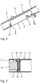
- FIGS. 12 and 13 another alternative of the set is described, wherein structurally identical components have the same reference numerals as in the previous Fig. 1 to 11 exhibit.
- the first fixing element 9 has a V-shaped cross-section, in which the complementarily shaped complementary element 5 of the battery unit 1 is introduced.
- the battery unit 1 has a recess 14. This can be brought into operative connection with the second fixing element 10.
- the second fixing element 10 is designed as an eccentric clamping element.
- the eccentric clamping element can be rotated about an axis of rotation 22 by means of an additional actuating lever (not shown) attachable thereto in such a way that the clamping element can be introduced into the indentation 14.
- an additional actuating lever not shown
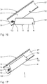
- FIGS. 14 and 15 is another alternative of the set shown. Structurally identical components have the same reference numerals as in the preceding Fig. 1 to 13 ,
- the first fixing means 9 has a rectangular cross section with a trapezoidal recess.
- the battery unit 1 has a complementary element 5 with a trapezoidal extension in cross section, which is complementary to the trapezoidal recess of the first fixing element 9 and can be introduced into it.
- an additional fixing means 11 in the form of a toggle joint, wherein the hinge is introduced by operating a corresponding lever in the second fixing of the receiving device 2, that the battery unit 1 is fixed in the final position.
- the second fixing element has a cross section, in which the additional fixing means 11 is introduced upon actuation of the lever.
- FIGS. 16 and 17 another alternative of the set is described.
- Structurally identical components have the same reference numerals as in the preceding Fig. 1 to 15 ,
- the complementary element 5 is designed as a pin-shaped extension which can be introduced into the first fixing means 9.
- the first fixing means on an opening through which the extension is passed.
- the first fixing means 9 is formed so flexible that the battery unit 1 is pivotally mounted on the axis of rotation 6 in the end position in the receiving device 2.
- the fixation of the battery unit 1 is achieved by the second fixing element, which is formed in the illustrated alternative as a through bolt.
- a plurality of pin-shaped extensions can also be used as the complementary element 5.
- the extensions may form contact pins for producing an electrically conductive connection to the drive unit.
- FIGS. 18 and 19 another alternative of the set is described, wherein structurally identical components have the same reference numerals as in the previous Fig. 1 to 17 exhibit.
- the complementary element 5 has a C-shaped cross-section, wherein additionally a gap 15 is provided.
- the gap 15 extends from a lowest point of the C-shaped cross section into the housing 12 of the battery unit 1.
- the complementary element 5 has a threaded bore 18 which, starting from the outside of the housing 12, is rotated by 90 ° relative to the gap 15 is and crosses this.
- the threaded bore 18 serves to receive the additional fixing means 11, which according to the illustrated variant is a clamping screw.
- the gap 15 makes it possible to move the two C-shaped legs of the complementary element 5 by means of the clamping screw toward each other. In this way, a play-free operative connection between the first fixing element 9 and the C-shaped complementary element 5 can be achieved.
- the battery unit 1 On the side opposite to the complementary element 5, the battery unit 1 has a height-reducing housing section 19 and a vertical through-opening 8.
- the vertical insertion opening 8 extends, starting from the outside of the cover plate 4, over the entire reduced height of the housing portion 19.
- the bicycle frame 3 and / or the receiving device 2 are formed to be complementary to the housing portion 19. In particular, they have a receiving opening 16 which is formed coaxially with the vertical through-opening 8 in the end position of the battery unit 1.
- a threaded nut 20 In the Cambridge the Cambridge 16 a threaded nut 20 is attached.
- the battery unit 1 is in the final position by means of a screw which is inserted through the insertion opening 8 and screwed into the threaded nut 20, fixed.
- FIG. 20 Another variant of the battery unit 1 or advantageous aspects thereof described.
- the general details of the battery unit 1 is on the description of the embodiment according to the Fig. 1 and 2 directed. Identical parts are provided with identical reference numerals.
- the receiving element 31 is connected by means of fastening means with the housing 12.
- screws 33 are used as fastening means.
- the screws 33 may in particular be Allen screws or Torx screws.
- the receiving element 31 is in particular detachably connected to the housing 12.
- the receiving element 32 can be exchangeable.
- the receiving element 32 is preferably made of metal or plastic.
- the plug-in axis 34 is formed as a hollow axle. It has a shaft 35. On the shaft 35, a contact element is arranged end. As a contact element is in particular a screw head 36th
- the contact element is preferably formed integrally with the shaft 35.
- a threaded portion 37 is arranged at the screw head 6 opposite end of the shaft 35.
- a contact element is screwed on the threaded portion 37.
- a contact element is in particular a nut 38th
- the thru axle 34 and the nut 38 are preferably made of metal, such as aluminum or titanium.
- the thru-axle 34 is held in the receiving element 31 by means of two reducing sleeves 39.
- the Reduzierhülsen 39 are made of an elastic material, in particular rubber. They have an insertable into the insertion opening 8 inner portion 40. They preferably have a stop shoulder 41. This is not mandatory.
- Reduzierhülsen 39 may also be provided a single continuous Reduzierhülse. This preferably has a length which is greater than the extension of the receiving element 31 along a transverse direction Q.
- the extension of the receiving element 31 in the transverse direction Q is smaller than that of the housing 12 in the transverse direction Q.
- the Reduzierhülsen 39 form decoupling elements for at least partial mechanical decoupling of the thru axle 34 from the housing 12. They allow in particular a mechanical decoupling of the bicycle frame 3 from the housing 12th
- the inner portion 40 of the Reduzierhülsen 39 has an outer cross section, which is adapted to the inner cross section of the insertion opening 8.
- the reducing sleeves 39 can be frictionally engaged in the through opening 8, i. be arranged in the receiving element 31.
- the Reduzierhülsen 39 have an inner cross-section, which is adapted to the outer cross section of the thru-axle 34.
- the plug-in axis 34 may in particular be mounted frictionally in the Reduzierhülsen 39.
- the storage can also have a low clearance.
- the stub axle 34 in particular with screwed nut 38, in the transverse direction Q relative to the receiving element 31 slidably.
- the thru-axle 34 is slightly tiltable in the introduced state in the receiving element 31 due to the elasticity of the Reduzierhülsen 39. This makes it possible to reduce a transmission of torsional forces from the bicycle frame 3 to the housing 12, in particular to eliminate as far as possible.
- the effective length of the thru-axle 34 can be adapted to the width of the receiving device 2.
- the effective length of the thru axle 34 is particularly continuously adjustable.
- a receiving element provided for this purpose can be provided in the receiving device 2, in particular in the bicycle frame 3.
- the receiving element is preferably made of the same material as the plug-in axis 34, in particular of aluminum.
- the fixing element 10 in particular in the form of a push-through pin, hin micsteckbar.
- the housing 12 can be mounted in a floating manner in the bicycle frame 3 or the receiving device 2 via the receiving element 31. In particular, it can be stored floating in the receiving device 2 or the bicycle frame 3, but without shaking.
- the thru-axle 34 is designed in several parts. In particular, it may have two or more components which can be inserted into one another. The components of the thru-axle 34 can in particular slide on one another. The thru-axle has a variable length in this case. As a result, loads on the bicycle frame 3 can be further reduced.
- the battery unit 1 has a second receiving element 32.
- the second receiving element 32 is arranged at the opposite end in the longitudinal direction L of the housing 12 of the battery unit 1.
- the receiving element 32 is exchangeable.
- the receiving element 32 is connected by means of one or more fastening means to the housing 12. It is in particular connected by four screws 42 to the housing 12. It is screwed in particular to the housing 12.
- the screws 42 are in particular Allen screws or Torx screws.
- the receiving element 32 is preferably made of metal or plastic.
- the receiving element 32 has the insertion opening 8.
- the insertion opening 8 is preferably formed as a slot or slot-like. It has an extension in the longitudinal direction L, which is greater than its extension perpendicular to the longitudinal direction L. This opens up a certain tolerance and / or a certain play in the longitudinal direction L for installation of the battery unit 1 in the receiving device 2, in particular in the bicycle frame. 3
- the receiving element 32 is in particular fastened from the outside to the housing 12.
- the cover plate 4 is preferably made of metal, plastic or a fiber composite material. It comprises at least portions of one or more of such materials.
- the cover plate 4 is preferably formed profiled. It comprises a plate-shaped area 43, to which two side legs 44 adjoin at the edge.
- the side legs 44 extend in the longitudinal direction. They have a length which is shorter than that of the plate-shaped region 43.
- the cover plate 4 thus has no side legs in the region of at least one end. It is designed in this area only as a flat plate. This allows a simplified and improved arrangement of the cover plate 4 on the bicycle frame. 3
- the cover plate 4 is detachably connected to the housing 12 of the battery unit 1. It is in particular pushed onto the housing 12 of the battery unit 1. In particular, it has a plurality of guide elements 45 which can be accommodated, in particular guided, in two grooves 46 arranged laterally on the housing 12 of the battery unit 1.
- the grooves 46 extend over substantially the entire length of the housing 12 of the Ackuech 1. They extend in particular over at least 70%, in particular at least 80%, in particular at least 90% of the length of the battery unit. 1
- the grooves 46 are interrupted.
- the cover plate 4 does not have to be inserted over its entire length in the grooves 46, but only over a fraction of the length.
- the guide elements 45 are each arranged in the region of a free end of the side legs 44. They are in particular inwardly from the side legs 44. They are aligned substantially parallel to the plate-shaped region 43. With the aid of the guide elements 45 and the grooves 46 can be achieved that the plate-shaped portion 43 spaced from the housing 12 of the battery unit 1 is arranged in the assembled state of the cover plate. Between the plate-shaped region 43 of the cover plate 4 and the housing 12 of the battery unit 1 in particular an air gap remains. As a result, the battery unit 1, in particular the housing 12 for the batteries 21, further protected. This also improves heat dissipation from the housing 12 of the battery unit 1. The distance between the plate-shaped portion 43 and the surface of the housing 12 of the battery unit 1 can be stabilized by strut-shaped projections. Such strut-shaped extensions can be arranged on the cover plate 4 and / or on the housing 12.
- the cover plate 4 is screwed by means of two screws 49 with the housing 12 of the battery unit 1.
- the screws 49 are preferably Allen screws or Torx screws. They are in particular in the longitudinal direction L in the housing 12 can be screwed.
- the cover plate 4 has a recess 47. Through the recess 47, a charging port for the battery 21 is accessible.
- the recess 47 can be closed with a cover element 48.
- the recess 47 is in particular tight, in particular watertight, closable with the aid of the cover element 48. It is especially protected against splashing water.
- the lid member 48 is made of a flexible and / or elastic material. It is preferably made of rubber.
- the cover element 48 is connected to the cover plate 4 and / or the housing 12 of the battery unit 1. It can be fastened in particular by means of the screws 49. In this case, in particular, a planar region 50 of the cover element 48 can be arranged between the cover plate 4 and the housing 12 of the battery unit 1. This results in a slightly elastic connection between the cover plate 4 and the housing 12 of the battery unit 1.
- the cover plate 4 may be due to the area 50 between it and the housing 12 of the battery unit 1 relative to the latter minimally displaceable and / or attenuated. This is for example to compensate advantageous from micro vibrations. As a result, in particular the electrical and / or electronic components of the battery unit 1 are better protected.
Landscapes
- Engineering & Computer Science (AREA)
- Chemical & Material Sciences (AREA)
- Mechanical Engineering (AREA)
- Combustion & Propulsion (AREA)
- Chemical Kinetics & Catalysis (AREA)
- Electrochemistry (AREA)
- General Chemical & Material Sciences (AREA)
- Transportation (AREA)
- Battery Mounting, Suspending (AREA)
Abstract
Eine Akkueinheit (1) für eine Antriebsvorrichtung für ein Fahrrad umfasst mindestens ein Entkopplungs-Element. Hierdurch ist eine Entkopplung eines Gehäuses (12) zur Aufnahme mindestens einen Akkus (21) vom Fahrradrahmen möglich. Die Akkueinheit (1) kann insbesondere elastisch gedämpft im Fahrradrahmen gelagert werden.A battery unit (1) for a drive device for a bicycle comprises at least one decoupling element. This enables a housing (12) to accommodate at least one battery (21) to be decoupled from the bicycle frame. The battery unit (1) can in particular be stored in the bicycle frame in an elastically damped manner.
Description
Die vorliegende Patentanmeldung nimmt die Priorität der deutschen Patentanmeldung
Die Erfindung betrifft eine Akkueinheit für eine Antriebsvorrichtung für ein Fahrrad. Außerdem betrifft die Erfindung ein Set mit einer Akkueinheit und einer Aufnahmeeinrichtung zur Aufnahme der Akkueinheit. Schließlich betrifft die Erfindung einen Fahrradrahmen mit einem derartigen Set. Die Erfindung betrifft weiterhin einen Fahrradrahmen. Schließlich betrifft die Erfindung eine Akkueinheit für eine Antriebsvorrichtung für ein Fahrrad.The invention relates to a battery unit for a drive device for a bicycle. Moreover, the invention relates to a set with a battery unit and a receiving device for receiving the battery unit. Finally, the invention relates to a bicycle frame with such a set. The invention further relates to a bicycle frame. Finally, the invention relates to a battery unit for a drive device for a bicycle.
Es gibt unterschiedliche Varianten von Fahrrädern mit Elektromotor. Bei derartigen Fahrrädern ist üblicherweise ein Akku am Fahrrad befestigt.There are different variants of bicycles with electric motor. In such bicycles, a battery is usually attached to the bicycle.
Aus der
Eine Aufgabe der Erfindung besteht darin, eine Akkueinheit für eine Antriebsvorrichtung für ein Fahrrad zu verbessern.An object of the invention is to improve a battery unit for a drive device for a bicycle.
Diese Aufgabe wird durch eine Akkueinheit gemäß Anspruch 1 gelöst. Der Kern der Erfindung besteht darin, die Akkueinheit mit einem Gehäuse zur Aufnahme des mindestens einen Akkus auszubilden, wobei das Gehäuse mindestens ein Aufnahme-Element zur Aufnahme mindestens eines Halteelements zum Befestigen der Akkueinheit in oder an einem Fahrradrahmen aufweist, und wobei mindestens ein mit dem Aufnahme-Element zusammenwirkendes Entkopplungs-Element zum zumindest teilweisen mechanischen Entkoppeln des im Aufnahme-Element aufgenommenen Halte-Elements vom Gehäuse vorgesehen ist.This object is achieved by a battery unit according to
Das Entkopplungs-Element ermöglicht es insbesondere, die Akkueinheit von auf den Rahmen des Fahrrads wirkenden Belastungen zu entkoppeln.The decoupling element makes it possible, in particular, to decouple the battery unit from loads acting on the frame of the bicycle.
Gemäß einem Aspekt der Erfindung umfasst das mindestens eine Entkopplungs-Element eine Steckachse, welche durch das mindestens eine Aufnahme-Element gesteckt ist.According to one aspect of the invention, the at least one decoupling element comprises a plug-in axis, which is inserted through the at least one receiving element.
Die Steckachse kann insbesondere aus Aluminium sein.The thru axle may be made of aluminum in particular.
Die Achse ist vorzugsweise entlang ihrer Axialrichtung verschiebbar. Dies ermöglicht eine schwimmende Lagerung des Gehäuses der Akkueinheit auf der Steckachse.The axis is preferably displaceable along its axial direction. This allows a floating mounting of the housing of the battery unit on the thru axle.
Das Entkopplungs-Element kann einteilig oder mehrteilig ausgebildet sein. Im Folgenden wird auch die Variante einer mehrteiligen Ausführung des Entkopplungs-Elements als Entkopplungs-Element nicht als Entkopplungs-Einrichtung bezeichnet.The decoupling element may be formed in one piece or in several parts. In the following, the variant of a multi-part design of the decoupling element as a decoupling element is not referred to as a decoupling device.
Gemäß einem weiteren Aspekt der Erfindung umfasst das mindestens eine Entkopplungs-Element mindestens ein elastisches und/oder flexibles Bauteil, mittels welchem die Steckachse in dem Aufnahme-Element gehalten ist.According to a further aspect of the invention, the at least one decoupling element comprises at least one elastic and / or flexible component, by means of which the thru-axle is held in the receiving element.
Durch die Elastizität und/oder Flexibilität dieses Bauteils wird eine zumindest teilweise mechanische Entkopplung der Steckachse vom Gehäuse der Akkueinheit ermöglicht. Hierdurch ist es insbesondere möglich, Kräfte, insbesondere Torsionskräfte, welche auf den Rahmen des Fahrrads wirken, vom Gehäuse der Akkueinheit zu entkoppeln.Due to the elasticity and / or flexibility of this component, an at least partial mechanical decoupling of the thru axle from the housing of the battery unit is made possible. This makes it possible in particular to decouple forces, in particular torsional forces, which act on the frame of the bicycle from the housing of the battery unit.
Das elastische und/oder flexible Bauteil ermöglicht außerdem eine gedämpfte Lagerung des Gehäuses der Akkueinheit. Hierdurch werden die elektrischen/elektronischen Komponenten geschützt. Dies führt zu einer besseren Haltbarkeit.The elastic and / or flexible component also allows a damped mounting of the housing of the battery unit. This protects the electrical / electronic components. This leads to a better durability.
Das elastische und/oder flexible Bauteil kann insbesondere als Reduzierhülse, welche in das mindestens eine Aufnahme-Element eingesetzt ist, ausgebildet sein. Die Reduzierhülse kann ein- oder mehrteilig ausgebildet sein. Es können insbesondere zwei Reduzierhülsen vorgesehen sein, welche von entgegengesetzten Seiten in die Aufnahme gesteckt werden.The elastic and / or flexible component can in particular be designed as a reduction sleeve, which is inserted into the at least one receiving element. The Reduzierhülse can be formed one or more parts. It can be provided in particular two Reduzierhülsen, which are inserted from opposite sides into the receptacle.
Vorzugsweise können die Reduzierhülsen jeweils eine Anlageschulter aufweisen, welche von außen an dem Aufnahme-Element anliegt.Preferably, the Reduzierhülsen each have a contact shoulder, which bears against the receiving element from the outside.
Die Reduzierhülsen können in dem in das Aufnahme-Element einzuführenden Bereich einen Außendurchmesser aufweisen, welcher gerade dem Innendurchmesser des Aufnahme-Elements entspricht. Sie können insbesondere formschlüssig am Aufnahme-Element anliegen.The Reduzierhülsen can have an outer diameter in the region to be introduced into the receiving element, which just corresponds to the inner diameter of the receiving element. In particular, they can rest positively on the receiving element.
Die Reduzierhülse ermöglicht eine Halterung der Steckachse im Aufnahme-Element. Die Steckachse kann insbesondere reibschlüssig im Aufnahme-Element gehalten sein. Sie kann hierbei entlang ihrer Axialrichtung verschiebbar sein.The Reduzierhülse allows a holder of the thru axle in the receiving element. The thru axle may in particular be held by friction in the receiving element. It can be displaceable along its axial direction.
Gemäß einem vorteilhaften Aspekt der Erfindung kann die Steckachse aufgrund der Elastizität und/oder Flexibilität des Bestandteils des Entkopplungs-Elements verkippbar im Aufnahme-Element angeordnet sein. Selbst ein sehr kleiner Verkippbarkeitsbereich genügt hierbei, um die Belastungen auf das Gehäuse der Akkueinheit spürbar zu reduzieren. Durch die Verkippbarkeit ist es insbesondere möglich, die Übertragung von Torsionskräften vom Fahrradrahmen auf das Gehäuse der Akkueinheit zu reduzieren, insbesondere - zumindest weitestgehend - zu eliminieren.According to an advantageous aspect of the invention, the plug-in axis can be arranged tiltable in the receiving element due to the elasticity and / or flexibility of the component of the decoupling element. Even a very small tilting range is sufficient to noticeably reduce the load on the housing of the battery unit. Due to the tiltability, it is particularly possible to reduce the transmission of torsional forces from the bicycle frame on the housing of the battery unit, in particular - at least largely - to eliminate.
Gemäß einem weiteren Aspekt der Erfindung kann am Gehäuse ein zweites Aufnahme-Element zur Aufnahme eines weiteren Halte-Elements zum Befestigen der Akkueinheit in oder an einem Fahrradrahmen vorgesehen sein.According to a further aspect of the invention may be provided on the housing, a second receiving element for receiving a further holding element for securing the battery unit in or on a bicycle frame.
Das zweite Aufnahme-Element kann insbesondere als Langloch ausgebildet sein. Es weist vorzugsweise eine Erstreckung parallel zur Längsrichtung der Akkueinheit auf. Das Langloch bildet ein zweites Entkopplungselement. Es ermöglicht insbesondere Toleranzen in Längsrichtung der Akkueinheit.The second receiving element may be formed in particular as a slot. It preferably has an extension parallel to the longitudinal direction of the battery unit. The slot forms a second decoupling element. It allows in particular tolerances in the longitudinal direction of the battery unit.
Gemäß einem Aspekt der Erfindung weist die Akkueinheit mindestens zwei Entkopplungselemente auf, wobei eines der Entkopplungselemente zu einer Entkopplung oder Toleranz in Längsrichtung der Akkueinheit führt, und wobei mindestens ein anderes der Entkopplungselemente zu einer Entkopplung oder Toleranz in Querrichtung und/oder gegenüber Verdrehungen um die Längsachse führt.According to one aspect of the invention, the battery unit has at least two decoupling elements, wherein one of the decoupling elements leads to a decoupling or tolerance in the longitudinal direction of the battery unit, and wherein at least one other of the decoupling elements to a decoupling or tolerance in the transverse direction and / or against rotation about the longitudinal axis leads.
Durch ein oder mehrere Entkopplungs-Elemente wird insbesondere eine schwimmende Lagerung der Akkueinheit, insbesondere eine Entkopplung des Gehäuses der Akkueinheit vom Fahrradrahmen, ermöglicht.By one or more decoupling elements in particular a floating mounting of the battery unit, in particular a decoupling of the housing of the battery unit from the bicycle frame, allows.
Gemäß einem weiteren Aspekt der Erfindung ist die Steckachse als Hohlachse ausgebildet.According to a further aspect of the invention, the plug-in axle is designed as a hollow axle.
Sie bildet insbesondere eine Aufnahme für ein Halteelement, mittels welchem sie im oder am Fahrradrahmen befestigt werden kann.It forms in particular a receptacle for a holding element, by means of which it can be fixed in or on the bicycle frame.
Gemäß einem weiteren Aspekt der Erfindung weist die Steckachse in ihrer Axialrichtung ein Spiel relativ zum Gehäuse der Akkueinheit auf.According to a further aspect of the invention, the plug-in axis in its axial direction on a game relative to the housing of the battery unit.
Gemäß einem weiteren Aspekt der Erfindung ist die Länge der Steckachse derart anpassbar, dass sie in Axialrichtung kein Spiel zum Fahrradrahmen aufweist.According to a further aspect of the invention, the length of the plug-in axle is adaptable such that it has no clearance to the bicycle frame in the axial direction.
Gemäß einem weiteren Aspekt der Erfindung weist die Steckachse an mindestens einem Ende einen Gewindeabschnitt auf. Sie kann auch an beiden Enden jeweils einen Gewindeabschnitt aufweisen. Hierbei kann es sich um ein Außengewinde zum Aufschrauben eines Anlageelements handeln.According to a further aspect of the invention, the plug-in axle has a threaded portion at at least one end. It can also have a threaded portion at both ends. This may be an external thread for screwing a contact element.
Die Steckachse kann insbesondere im Bereich eines ihrer Enden eine Anlagefläche, insbesondere in Form eines Schraubenkopfs, insbesondere in Form einer Sechskantschraube, aufweisen. Sie weist in diesem Fall vorzugsweise am gegenüberliegenden Ende einen Außengewindeabschnitt auf, auf welchem ein Anlageelement in Form einer Sechskantmutter aufschraubbar ist. Mit Hilfe des Außengewindes ist es möglich, das Anlageelement unterschiedlich weit auf die Steckachse aufzuschrauben. Hierdurch ist die effektive Länge der Steckachse anpassbar. Die Länge der Steckachse kann insbesondere derart anpassbar sein, dass sie beidseitig von innen an einer hierfür vorgesehenen Anlagefläche im Fahrradrahmen oder einer speziellen Aufnahmeeinrichtung anliegt.The plug-in axis may have, in particular in the region of one of its ends, a contact surface, in particular in the form of a screw head, in particular in the form of a hexagonal screw. It has in this case preferably at the opposite end to a male threaded portion on which a contact element in the form of a hex nut can be screwed. With the help of the external thread, it is possible to unscrew the contact element to different heights on the thru-axle. As a result, the effective length of the thru axle is customizable. The length of the thru-axle may in particular be adaptable such that it bears on both sides from the inside on a contact surface provided in the bicycle frame or a special receiving device.
Gemäß einer Alternative weist die Steckachse beidseitig ein Innengewinde zur Aufnahme eines Halteelements, insbesondere in Form einer Schraube, auf. Dies ermöglicht eine direkte Fixierung der Steckachse in oder an der Aufnahmeeinrichtung oder einem Fahrradrahmen.According to one alternative, the plug-in axis on both sides of an internal thread for receiving a retaining element, in particular in the form of a screw on. This allows a direct fixation of the thru axle in or on the receiving device or a bicycle frame.
Gemäß einem weiteren Aspekt der Erfindung ist die Steckachse mehrteilig ausgebildet, wobei ein Teil mit einem Gewindeabschnitt über eine Steckverbindung mit einem weiteren Teil verbunden ist.According to a further aspect of the invention, the plug-in axle is formed in several parts, wherein a part is connected to a threaded portion via a plug connection with another part.
Dies führt dazu, dass die Steckachse eine variable Länge aufweist. Hierdurch können auf den Fahrradrahmen oder die Aufnahmeeinrichtung wirkende Kräfte reduziert werden.This results in the thru axle having a variable length. As a result, acting on the bicycle frame or the receiving device forces can be reduced.
Gemäß einem weiteren Aspekt der Erfindung ist das mindestens eine Aufnahme-Element reversibel von außen am Gehäuse der Akkueinheit befestigt. Vorzugsweise sind beide Aufnahme-Elemente reversibel von außen am Gehäuse der Akkueinheit befestigt. Das oder die Aufnahme-Elemente sind vorzugsweise austauschbar.According to a further aspect of the invention, the at least one receiving element is reversibly fixed from the outside to the housing of the battery unit. Preferably, both receiving elements are reversibly mounted from the outside of the housing of the battery unit. The one or more receiving elements are preferably interchangeable.
Das oder die Austausch-Elemente sind insbesondere mit dem Gehäuse der Akkueinheit verschraubt. Sie können insbesondere jeweils mittels vier Schrauben, insbesondere in Form von Inbus- oder Torx-Schrauben mit dem Gehäuse der Akkueinheit verschraubt sein. Dies ermöglicht eine sichere, austauschbare Verbindung der Aufnahme-Elemente mit dem Gehäuse der Ackueinheit.The one or more replacement elements are bolted in particular to the housing of the battery unit. In particular, they can in each case by means of four screws, in particular in the form of Allen screws or Torx screws must be bolted to the housing of the battery unit. This allows a secure, interchangeable connection of the recording elements with the housing of the Ackueinheit.
Gemäß einem weiteren Aspekt der Erfindung weist die Akkueinheit eine Abdeckung zum Verschließen einer Aufnahmeeinrichtung zur Aufnahme der Akkueinheit auf, wobei die Abdeckung reversibel am Gehäuse fixierbar ist.According to a further aspect of the invention, the battery unit has a cover for closing a receiving device for receiving the battery unit, wherein the cover is reversibly fixable to the housing.
Mittels der Abdeckung ist insbesondere eine Aufnahmeöffnung, durch welche die Akkueinheit in die Aufnahmeeinrichtung und/oder den Fahrradrahmen einführbar ist, zuverlässig, insbesondere dicht, insbesondere wasserdicht, verschließbar.By means of the cover is in particular a receiving opening, through which the battery unit is inserted into the receiving device and / or the bicycle frame, reliable, in particular tight, in particular waterproof, closed.
Als Abdeckung kann insbesondere eine Platte aus Metall, Kunststoff oder Faserverbundstoff vorgesehen sein.As a cover may be provided in particular a plate made of metal, plastic or fiber composite.
Die Abdeckung ist vorzugsweise mit dem Gehäuse der Akkueinheit verschraubt.The cover is preferably screwed to the housing of the battery unit.
Gemäß einem weiteren Aspekt der Erfindung ist die Abdeckung in einer am Gehäuse der Akkueinheit ausgebildeten Nut geführt gelagert. Die Abdeckung kann insbesondere auf das Gehäuse der Akkueinheit aufgeschoben und dort mittels Schrauben fixiert werden.According to a further aspect of the invention, the cover is guided guided in a formed on the housing of the battery unit groove. The cover can be pushed in particular onto the housing of the battery unit and fixed there by means of screws.
Die Abdeckung ist vorzugsweise austauschbar.The cover is preferably replaceable.
Gemäß einem weiteren Aspekt der Erfindung ist die Abdeckung als Profilelement ausgebildet. Sie kann insbesondere einen U-förmigen Querschnitt aufweisen. Sie kann vorzugsweise als Platte mit seitlich vorstehenden Schenkeln ausgebildet sein.According to a further aspect of the invention, the cover is designed as a profile element. It may in particular have a U-shaped cross-section. It may preferably be formed as a plate with laterally projecting legs.
Eine weitere Aufgabe der Erfindung besteht darin, die Anordnung einer Akkueinheit für eine Antriebsvorrichtung für ein Fahrrad am Fahrrad zu verbessern.Another object of the invention is to improve the arrangement of a battery unit for a drive device for a bicycle on the bicycle.
Diese Aufgabe wird durch ein Set mit einer Akkueinheit gemäß der vorliegenden Erfindung und einer Aufnahmeeinrichtung zur Aufnahme der Akkueinheit gelöst.This object is achieved by a set with a battery unit according to the present invention and a receiving device for receiving the battery unit.
Der Kern der Erfindung besteht darin, die Akkueinheit schwimmend in der Aufnahmeeinrichtung zu lagern.The essence of the invention is to store the battery unit floating in the receiving device.
Hierdurch werden Belastungen auf das Gehäuse der Akkueinheit reduziert.As a result, loads are reduced to the housing of the battery unit.
Gemäß einem Aspekt der Erfindung ist es möglich, die Akkueinheit mittels zweier Durchsteckbolzen reversibel in der Aufnahmeeinrichtung zu fixieren.According to one aspect of the invention, it is possible to reversibly fix the battery unit in the receiving device by means of two through bolts.
Hierdurch wird eine besonders einfache und sichere Fixierung der Akkueinheit in der Aufnahmeeinrichtung ermöglicht.This allows a particularly simple and secure fixation of the battery unit in the receiving device.
Die Akkueinheit ist vorzugsweise schwimmend in der Aufhahmeeinrichtung, insbesondere im Fahrradrahmen, gelagert. Hierunter sei verstanden, dass sich die Akkueinheit relativ zur Aufnahmeeinrichtung, insbesondere relativ zum Rahmen des Fahrrads, verschieben und/oder verdrehen kann. Der maximale Bewegungsumfang der Akkueinheit kann hierbei sehr klein sein. Er entspricht jedoch dem Umfang der maximalen Verformbarkeit des Bestandteils des Fahrradrahmens, in welches die Akkueinheit eingesetzt wird. Er entspricht insbesondere der maximalen Verformbarkeit des Unterrohrs des Fahrradrahmens beim normalen Gebrauch des Fahrrads, insbesondere im Downhill-Einsatz. Dies führt insbesondere dazu, dass eine Übertragung von Torsionskräften vom Rahmen auf das Gehäuse der Akkueinheit reduziert, insbesondere vermieden, wird.The battery unit is preferably floating in the receiving device, in particular in the bicycle frame stored. This is understood to mean that the battery unit relative to the receiving device, in particular relative to the frame of the bicycle, move and / or can rotate. The maximum range of motion of the battery unit can be very small here. However, it corresponds to the extent of the maximum deformability of the component of the bicycle frame, in which the battery unit is used. It corresponds in particular to the maximum deformability of the down tube of the bicycle frame during normal use of the bicycle, especially in downhill use. This leads in particular to the fact that a transmission of torsional forces from the frame to the housing of the battery unit is reduced, in particular avoided.
Die Aufnahmeeinrichtung ist insbesondere im Fahrradrahmen, beispielsweise im Unterrohr, im Sattelrohr oder im Oberrohr integriert. Sie kann insbesondere fest mit dem Fahrradrahmen verbunden und mit diesem einteilig ausgebildet sein. Insbesondere weist die Aufnahmeeinrichtung eine Einführöffnung auf, durch welche die Akkueinheit aufgenommen wird.The receiving device is integrated in particular in the bicycle frame, for example in the down tube, in the seat tube or in the top tube. It may in particular be firmly connected to the bicycle frame and formed integrally therewith. In particular, the receiving device has an insertion opening, through which the battery unit is received.
Gemäß einem Aspekt der Erfindung weist zumindest einer der Durchsteckbolzen, insbesondere beide, einen Gewindeabschnitt auf.According to one aspect of the invention, at least one of the through bolts, in particular both, a threaded portion.
Bei den Durchsteckbolzen kann es sich insbesondere um Schrauben handeln.The through bolts may be in particular screws.
Gemäß einem weiteren Aspekt der Erfindung ist ein hierzu passender Gewindeabschnitt in der Aufnahmeeinrichtung vorgesehen. Der oder die Durchsteckbolzen können insbesondere in die Aufnahmeeinrichtung einschraubbar sein. Es kann auch vorgesehen sein, eine zum Gewindeabschnitt des oder der Durchsteckbolzen passende Mutter in den Fahrradrahmen zu integrieren.According to a further aspect of the invention, a matching threaded portion is provided in the receiving device. The one or more through bolts can be screwed in particular in the receiving device. It may also be provided to integrate a matching nut to the threaded portion of the bolt or the mother in the bicycle frame.
Gemäß einer Alternative werden die Durchsteckbolzen mittels einer separaten Mutter fixiert.According to an alternative, the through bolts are fixed by means of a separate nut.
Die Durchsteckbolzen können jeweils durch eine Durchstecköffnung eines Gehäuses der Akkueinheit durchgesteckt werden. Sie können auch mit der Akkueinheit verschraubt werden.The through bolts can be pushed through each through an insertion opening of a housing of the battery unit. They can also be screwed to the battery unit.
Die Durchsteckbolzen können jeweils durch eine oder zwei Durchstecköffnungen der Aufnahmeeinrichtung hindurchgesteckt werden. Sie können auch mit der Aufnahmeeinrichtung verschraubt werden.The through bolts can be inserted through one or two through-openings of the receiving device in each case. They can also be screwed to the receiving device.
Die Durchsteckbolzen durchdringen insbesondere jeweils mindestens eine Öffnung in der Aufnahmeeinrichtung und/oder der Akkueinheit, insbesondere einem Gehäuse derselben, vollständig. Vorteilhafterweise ist mindestens eine dieser Öffnungen in der Aufnahmeeinrichtung und/oder der Akkueinheit als Langloch ausgebildet. Hierdurch kann ein Toleranzausgleich gewährleistet werden.The through bolts in particular penetrate in each case at least one opening in the receiving device and / or the battery unit, in particular a housing thereof, completely. Advantageously, at least one of these openings in the receiving device and / or the battery unit is designed as a slot. As a result, a tolerance compensation can be ensured.
Die Durchsteckbolzen können jeweils einen konischen Bereich, insbesondere einen konischen Kopf, aufweisen. Dies kann zu einer zentrierenden Klemmung der Akkueinheit in der Aufnahmeeinrichtung genutzt werden.The through bolts can each have a conical region, in particular a conical head. This can be used to a centering clamping of the battery unit in the receiving device.
Gemäß einem weiteren Aspekt der Erfindung ist mindestens ein Bestandteil der Akkueinheit spielfrei in der Aufnahmeeinrichtung fixierbar. Es ist insbesondere möglich, die Steckachse spielfrei in der Aufnahmeeinrichtung zu fixieren.According to a further aspect of the invention, at least one component of the rechargeable battery unit can be fixed without play in the receiving device. It is particularly possible to fix the thru-axle without clearance in the receiving device.
Hierdurch kann insbesondere ein unerwünschtes Klappern der Akkueinheit in der Aufnahmeeinrichtung vermieden werden.In this way, in particular unwanted rattling of the battery unit in the receiving device can be avoided.
Gemäß einem weiteren Aspekt der Erfindung ist die Akkueinheit mittels einer Führung, insbesondere einer Kulissenführung, in die Aufnahmeeinrichtung einführbar. Sie kann insbesondere schräg, insbesondere unter einem Winkel im Bereich von 10° bis 60°, insbesondere im Bereich von weniger als 45°, zur Längsachse eines Rahmenrohres, in welchem die Aufnahmeeinrichtung angeordnet ist, einführbar sein. Insbesondere weist die Akkueinheit hierfür eine Abdeckplatte auf. Die Abdeckplatte ist vorteilhafterweise einteilig mit dem Gehäuse der Akkueinheit ausgebildet.According to a further aspect of the invention, the battery unit can be inserted into the receiving device by means of a guide, in particular a slide guide. It can in particular obliquely, in particular at an angle in the range of 10 ° to 60 °, in particular in the range of less than 45 °, to the longitudinal axis of a frame tube, in which the receiving device is arranged, be insertable. In particular, the battery unit for this purpose has a cover plate. The cover plate is advantageously formed integrally with the housing of the battery unit.
Gemäß einem weiteren Aspekt der Erfindung kann die Abdeckplatte derart ausgebildet sein, dass diese an das Gehäuse der Akkueinheit montierbar, insbesondere anschraubbar oder ansteckbar, ist.According to a further aspect of the invention, the cover plate can be designed such that it can be mounted on the housing of the battery unit, in particular screwed or plugged.
Gemäß einem weiteren Aspekt der Erfindung ist die Aufnahmeeinrichtung flüssigkeitsdicht ausgebildet. Sie kann insbesondere mittels der Akkueinheit flüssigkeitsdicht verschließbar sein. Vorteilhafterweise ist an der zur Aufnahmeeinrichtung gerichteten Innenseite der Abdeckplatte eine elastische Dichtlippe angeordnet, welche beim Einbringen der Akkueinheit in die Aufnahmeeinrichtung diese flüssigkeitsdicht verschließt.According to a further aspect of the invention, the receiving device is formed liquid-tight. It can be closed in a liquid-tight manner, in particular by means of the battery unit. Advantageously, an elastic sealing lip is arranged on the inner side of the cover plate directed towards the receiving device, which seals the liquid-tight manner when the battery unit is inserted into the receiving device.
Gemäß einem weiteren Aspekt der Erfindung ist mindestens ein weiteres, separates Fixier- und/oder Klemmmittel zur Fixierung und/oder Verklemmung der Akkueinheit in der Aufnahmeeinrichtung vorgesehen. Hierdurch kann der Sitz der Akkueinheit in der Aufnahmeeinrichtung weiter verbessert werden.According to a further aspect of the invention, at least one further, separate fixing and / or clamping means is provided for fixing and / or clamping the battery unit in the receiving device. In this way, the seat of the battery unit in the receiving device can be further improved.
Gemäß einem weiteren Aspekt der Erfindung ist die Akkueinheit werkzeuglos in der Aufnahmeeinrichtung fixierbar. Sie ist insbesondere manuell reversibel in die Aufnahmeeinrichtung einsetzbar. Sie kann insbesondere werkzeuglos aus der Aufnahmeeinrichtung entnehmbar sein.According to a further aspect of the invention, the battery unit can be fixed without tools in the receiving device. In particular, it can be reversibly inserted manually into the receiving device. In particular, it can be removed from the receiving device without tools.
Alternativ hierzu kann es vorteilhaft sein, die Akkueinheit und/oder die Aufnahmeeinrichtung derart auszubilden, dass die Akkueinheit lediglich mit Hilfe eines Spezialwerkzeugs aus der Aufnahmeeinrichtung entnehmbar ist. Sie kann insbesondere verschließbar in der Aufnahmeeinrichtung angeordnet sein. Zur Entnahme der Akkueinheit aus der Aufnahmeeinrichtung ist in diesem Fall ein spezieller Schlüssel notwendig. Dies bietet einen Schutz gegen ein unerwünschtes Entfernen der Akkueinheit aus der Aufhahmeeinrichtung, insbesondere einen Schutz gegen Diebstahl.Alternatively, it may be advantageous to form the battery unit and / or the receiving device such that the battery unit can be removed only with the aid of a special tool from the receiving device. It can be arranged in particular closable in the receiving device. To remove the battery unit from the receiving device a special key is necessary in this case. This provides protection against unwanted removal of the battery unit from the receiving device, in particular protection against theft.
Eine weitere Aufgabe der Erfindung besteht darin, einen Fahrradrahmen zu verbessern.Another object of the invention is to improve a bicycle frame.
Diese Aufgabe wird durch einen Fahrradrahmen mit einem Set gemäß der vorhergehenden Beschreibung gelöst.This object is achieved by a bicycle frame with a set according to the preceding description.
Die Vorteile ergeben sich aus dem vorgehend Beschriebenen.The advantages arise from what has been described above.
Die Aufgabe wird insbesondere durch einen Fahrradrahmen mit einer Aufnahmeeinrichtung zur Aufnahme einer Akkueinheit für eine Antriebsvorrichtung gelöst, wobei die Aufnahmeeinrichtung ein erstes und ein zweites Halte- oder Fixierelement zur Fixierung mindestens eines Bestandteils der Akkueinheit aufweist, wobei das erste Halte- oder Fixierelement derart ausgebildet ist, dass es eine rotatorische oder eine lineare Einführung der Akkueinheit in die Aufnahmeeinrichtung ermöglicht und wobei das zweite Halte- oder Fixierelement derart ausgebildet ist, dass es eine lösbare Fixierung mindestens eines Bestandteils der Akkueinheit, insbesondere deren Steckachse, in die Aufnahmeeinrichtung ermöglicht.The object is achieved in particular by a bicycle frame with a receiving device for receiving a battery unit for a drive device, wherein the receiving device has a first and a second holding or fixing element for fixing at least one component of the battery unit, wherein the first holding or fixing element is formed in that it allows a rotary or a linear introduction of the battery unit into the receiving device and wherein the second holding or fixing element is designed such that it allows a releasable fixation of at least one component of the battery unit, in particular its thru axle, in the receiving device.
Die beiden Fixierelemente sind in einer Längsrichtung der Aufnahmeeinrichtung um einen Abstand d voneinander beabstandet. Der Abstand d liegt insbesondere im Bereich von 5 cm bis 50 cm, insbesondere im Bereich von 10 cm bis 40 cm.The two fixing elements are spaced apart in a longitudinal direction of the receiving device by a distance d. The distance d is in particular in the range of 5 cm to 50 cm, in particular in the range of 10 cm to 40 cm.
Mittels der Aufnahmeeinrichtung wird eine vorgegebene Endposition für die Akkueinheit definiert. Hierunter sei die Position der Akkueinheit im vollständig in die Aufnahmeeinrichtung eingesetzten, insbesondere im fixierten Zustand, bezeichnet.By means of the receiving device, a predetermined end position for the battery unit is defined. This is the position of the battery unit in the fully inserted into the receiving device, in particular in the fixed state referred to.
Gemäß einem Aspekt der Erfindung kann die Endposition justierbar sein. Sie kann insbesondere mit Hilfe eines oder beider der Fixierelemente justierbar sein.According to one aspect of the invention, the end position may be adjustable. It can be adjustable in particular with the aid of one or both of the fixing elements.
Gemäß einem weiteren Aspekt der Erfindung ist die Aufnahmeeinrichtung vollständig einem Rohr des Fahrradrahmens integriert. Sie kann insbesondere im Unterrohr, im Oberrohr oder im Sattelrohr des Fahrradrahmens integriert sein.According to a further aspect of the invention, the receiving device is completely integrated with a tube of the bicycle frame. It can be integrated in particular in the down tube, in the top tube or in the seat tube of the bicycle frame.
Die Aufnahmeeinrichtung kann insbesondere einen Bestandteil des Fahrradrahmens bilden.The receiving device may in particular form part of the bicycle frame.
Sie kann insbesondere derart im Unterrohr des Fahrradrahmens integriert sein, dass die Akkueinheit von unten in die Aufnahmeeinrichtung einsetzbar ist. Die Oberseite des Unterrohrs kann dadurch unverändert für Anbauteile, beispielsweise einen Flaschenhalter, oder zur Anlenkung eines gefederten Hinterbaus des Fahrrads verwendet werden.In particular, it can be integrated in the down tube of the bicycle frame such that the battery unit can be inserted from below into the receiving device. The top of the down tube can thereby be used unchanged for attachments, such as a bottle cage, or for articulation of a sprung rear end of the bicycle.
Gemäß einem weiteren Aspekt der Erfindung ist die Aufnahmeeinrichtung und/oder die Akkueinheit, insbesondere deren Gehäuse, derart ausgebildet, dass sie zu einer Verstärkung, insbesondere zu einer Versteifung, insbesondere in Querrichtung, des Fahrradrahmens in diesem Bereich beitragen. Sie können insbesondere profilierte Elemente aufweisen, welche sich in Längsrichtung erstrecken.According to a further aspect of the invention, the receiving device and / or the battery unit, in particular its housing, are designed such that they contribute to a reinforcement, in particular to a stiffening, in particular in the transverse direction, of the bicycle frame in this area. In particular, they can have profiled elements which extend in the longitudinal direction.
Gemäß einem weiteren Aspekt der Erfindung ist die Akkueinheit, insbesondere deren Gehäuse, derart ausgebildet, das daraus eine Reduzierung der vom Fahrradrahmen auf das Akkugehäuse übertragenen Kräfte resultiert. Vorteilhafterweise weist das Gehäuse hierzu an Berührungsflächen mit den Fixierelementen elastische Zwischenelemente auf, welche die auftretenden Kräfte im Fahrradrahmen dämpfen. Insbesondere sind die Zwischenelemente aus Gummi ausgebildet. Eine Ausbildung der Zwischenelemente aus anderen Materialien, welche ebenfalls eine Dämpfungsfunktion aufweisen, ist ebenfalls denkbar.According to a further aspect of the invention, the battery unit, in particular its housing, is designed in such a way as to result in a reduction of the forces transmitted from the bicycle frame to the battery housing. Advantageously, the housing has for this purpose on contact surfaces with the fixing elastic intermediate elements which dampen the forces occurring in the bicycle frame. In particular, the intermediate elements are made of rubber. A design of the intermediate elements of other materials, which also have a damping function, is also conceivable.
Gemäß einem weiteren Aspekt der Erfindung ist die Akkueinheit vollständig im Fahrradrahmen integrierbar. Die Akkueinheit kann insbesondere derart ausgebildet sein, dass die Kontur des jeweiligen Rahmenrohrs, insbesondere der sich an die Aufnahmeeinrichtung anschließenden Bereiche, im eingesetzten Zustand der Akkueinheit durch deren Oberfläche vervollständigt wird. Die Kontur des jeweiligen Rahmenrohrs kann insbesondere formschlüssig, im Wesentlichen kantenfrei, durch die Oberfläche der Akkueinheit, insbesondere deren Gehäuse, vervollständigt werden.According to a further aspect of the invention, the battery unit is completely integrated in the bicycle frame. The battery unit may in particular be designed such that the contour of the respective frame tube, in particular of the adjoining the receiving device areas, is completed in the inserted state of the battery unit by the surface thereof. The contour of the respective frame tube can in particular be positively, substantially edge-free, completed by the surface of the battery unit, in particular their housing.
Gemäß einem weiteren Aspekt der Erfindung sind die Aufnahmeeinrichtung und die Akkueinheit zumindest bereichsweise komplementär zueinander ausgebildet. Die Aufnahmeeinrichtung kann insbesondere einen formschlüssigen Sitz für die Akkueinheit bilden.According to a further aspect of the invention, the receiving device and the battery unit are at least partially complementary to each other. The receiving device may in particular form a positive fit for the battery unit.
Die Aufnahmeeinrichtung weist insbesondere einen Innenquerschnitt auf. Die Akkueinheit weist insbesondere einen Außenquerschnitt auf. Hierbei sind der Innenquerschnitt der Aufnahmeeinrichtung und der Außenquerschnitt der Akkueinheit insbesondere derart aneinander angepasst, dass sie mehrere Anlageflächen bilden.The receiving device has in particular an inner cross section. The battery unit has in particular an outer cross section. Here, the inner cross section of the receiving device and the outer cross section of the battery unit are in particular adapted to each other so that they form a plurality of contact surfaces.
Gemäß einem weiteren Aspekt der Erfindung weist die Akkueinheit und/oder die Aufnahmeeinrichtung einen sich in Längsrichtung verändernden Querschnitt auf. Es ist insbesondere möglich, auf einem der beiden Elemente stift- oder rippenartige Vorsprünge auszubilden, welche mit dazu passenden Aussparungen, insbesondere Nuten, zusammenwirken. Auf diese Weise kann der Sitz der Akkueinheit in der Aufnahmeeinrichtung und damit im Fahrradrahmen weiter verbessert werden. Die Akkueinheit kann dadurch insbesondere beim Fixieren zusätzlich entlang einer Kulisse geführt und damit zusätzlich verklemmt werden.According to a further aspect of the invention, the battery unit and / or the receiving device has a cross-section that changes in the longitudinal direction. It is particularly possible to form pin-like or rib-like projections on one of the two elements, which cooperate with matching recesses, in particular grooves. In this way, the seat of the battery unit in the receiving device and thus in the bicycle frame can be further improved. The battery unit can thereby be guided in particular during fixing additionally along a backdrop and thus additionally jammed.
Gemäß einer besonders vorteilhaften Ausführungsform können die Nuten derart ausgebildet sein, dass die Akkueinheit beim Einsetzen in die Aufnahmeeinrichtung in eine Übertotpunktstellung gebracht wird. Hierdurch kann die Gefahr eines unbeabsichtigten Herausfallens der Akkueinheit aus der Aufnahmeeinrichtung weiter reduziert werden. Vorzugsweise wird die Akkueinheit in diesem Fall durch ein oder mehrere elastische Mittel in ihre Endposition in der Aufnahmeeinrichtung gedrückt.According to a particularly advantageous embodiment, the grooves may be formed such that the battery unit is brought into an over-center position upon insertion into the receiving device. As a result, the risk of unintentional falling out of the battery unit from the receiving device can be further reduced. Preferably, the battery unit is pressed in this case by one or more elastic means in its end position in the receiving device.
Gemäß einem weiteren Aspekt der Erfindung ist das erste Fixierelement und/oder das zweite Fixierelement derart ausgebildet, dass es eine spielfreie Fixierung der Akkueinheit in der Aufnahmeeinrichtung ermöglicht.According to a further aspect of the invention, the first fixing element and / or the second fixing element is designed such that it enables a backlash-free fixation of the battery unit in the receiving device.
Es kann insbesondere formschlüssig mit der Akkueinheit zusammenwirken. Es kann auch klemmend mit der Akkueinheit zusammenwirken.It can in particular interact positively with the battery unit. It can also interact with the battery unit by clamping.
Gemäß einem weiteren Aspekt der Erfindung weist das zweite Fixierelement der Aufnahmeeinrichtung eine Auswahl aus folgende Liste auf: ein Kniehebelgelenk, insbesondere ein Kniehebelgelenk mit einer Übertotpunktstellung, eine Exzenterschraube, welche insbesondere als Spiralexzenterschraube ausgebildet ist, eine Klemmplatte, einen Spannhebel, welcher das Gehäuse der Akkueinheit axial zur Schwenkachse des Spannhebels spannt, einen Verrastmechanismus, einen oder mehrere Magnete.According to a further aspect of the invention, the second fixing of the receiving device has a selection of the following list: a toggle joint, in particular a toggle joint with an over-center position, an eccentric, which is designed in particular as a spiral eccentric, a clamping plate, a clamping lever, which the housing of the battery unit axially clamped to the pivot axis of the clamping lever, a latching mechanism, one or more magnets.
Gemäß einem weiteren Aspekt der Erfindung ist mindestens ein zusätzliches Fixiermittel zur Fixierung der Akkueinheit in der Aufnahmeeinrichtung vorgesehen. Das zusätzliche Fixiermittel dient insbesondere zur Fixierung der Akkueinheit in der vollständig in die Aufnahmeeinrichtung eingesetzten Stellung.According to a further aspect of the invention, at least one additional fixing means is provided for fixing the battery unit in the receiving device. The additional fixing means is used in particular for fixing the battery unit in the fully inserted into the receiving device position.
Als Fixiermittel kann beispielsweise eine Schraube, insbesondere eine Klemmschraube, vorgesehen sein. Mit Hilfe der Klemmschraube kann die Akkueinheit im Fahrradrahmen und/oder in der Aufnahmeeinrichtung verklemmt werden. Die Klemmschraube kann auch mit einem der Fixierelemente zusammenwirken.As a fixing, for example, a screw, in particular a clamping screw can be provided. With the help of the clamping screw, the battery unit can be jammed in the bicycle frame and / or in the receiving device. The clamping screw can also interact with one of the fixing elements.
Als Fixiermittel kann auch ein Keil, eine Exzenterscheibe, ein Kniehebelgelenk, insbesondere ein Kniehebelgelenk mit einer Übertotpunktstellung, oder ein anderes Fixiermittel dienen.As a fixing means can also serve a wedge, an eccentric, a toggle joint, in particular a toggle joint with an over-center position, or other fixative.
Das zusätzliche Fixiermittel kann unabhängig von den Fixierelementen der Aufnahmeeinrichtung sein, insbesondere unabhängig von diesen mit der Akkueinheit zusammenwirken. Das zusätzliche Fixiermittel kann auch mit einem oder beiden der Fixierelemente der Aufnahmeeinrichtung zusammenwirken.The additional fixing means may be independent of the fixing elements of the receiving device, in particular interact independently of these with the battery unit. The additional fixing means may also cooperate with one or both of the fixing elements of the receiving device.
Gemäß einem weiteren Aspekt der Erfindung ist ein elastisches Mittel vorgesehen, welches im vollständig in die Aufnahmeeinrichtung eingesetzten Zustand der Akkueinheit zwischen der Aufnahmeeinrichtung und der Akkueinheit angeordnet ist. Es liegt in diesem Zustand insbesondere an beiden an. Es ist in diesem Zustand insbesondere leicht komprimiert. Hierdurch wird eine Kraft auf die Akkueinheit ausgeübt. Dies führt zu einem besonders sicheren, verwackelungsfreien Sitz der Akkueinheit in der Aufnahmeeinrichtung.According to a further aspect of the invention, an elastic means is provided, which is arranged in the completely inserted into the receiving device state of the battery unit between the receiving device and the battery unit. It is in this state, in particular to both. In particular, it is slightly compressed in this state. This will exerted a force on the battery unit. This leads to a particularly safe, shake-free fit of the battery unit in the receiving device.
Es kann insbesondere vorgesehen sein, einen Bereich der Aufnahmeeinrichtung mit einer Lage aus einem elastischen Material auszukleiden. Dies kann auch zum Ausgleich von Toleranzen dienen.It can be provided in particular to line a region of the receiving device with a layer of an elastic material. This can also be used to compensate for tolerances.
Gemäß einem weiteren Aspekt der Erfindung ist das erste Fixierelement der Aufnahmeeinrichtung zur Zusammenwirkung mit einem Komplementärelement an der Akkueinheit ausgebildet. Eines dieser beiden Elemente ist insbesondere als Achse ausgebildet.According to a further aspect of the invention, the first fixing element of the receiving device is designed to interact with a complementary element on the battery unit. One of these two elements is designed in particular as an axle.
Das andere Element kann gabelförmig, das heißt mit einem C-förmigen Querschnitt, stiftförmig, klauenförmig oder als Einhängelasche ausgebildet sein. Hierbei kann insbesondere die freie Weite des Aufnahmebereichs verstellbar sein, insbesondere mit Hilfe einer Klemmschraube.The other element may be fork-shaped, that is, with a C-shaped cross-section, pin-shaped, claw-shaped or formed as a suspension loop. In this case, in particular the free width of the receiving area can be adjusted, in particular by means of a clamping screw.
Die Achse kann sich über die gesamte Breite der Aufnahmeeinrichtung erstrecken. Alternativ hierzu können auch auf gegenüberliegenden Seiten der Aufnahmeeinrichtung bolzenartige Vorsprünge vorgesehen sein. Mit Hilfe einer durchgehenden Achse kann die Quersteifigkeit der Aufnahmeeinrichtung erhöht werden. Zur Gewichtsersparnis kann die Achse als Hohlachse ausgebildet sein. Entsprechende bolzenartige Vorsprünge können ebenfalls im Bereich des zweiten Fixierelements an den gegenüberliegenden Seiten der Aufnahmeeinrichtung ausgebildet sein.The axis may extend over the entire width of the receiving device. Alternatively, bolt-like projections may also be provided on opposite sides of the receiving device. With the help of a continuous axis, the transverse rigidity of the receiving device can be increased. To save weight, the axle may be formed as a hollow axle. Corresponding bolt-like projections may also be formed in the region of the second fixing element on the opposite sides of the receiving device.
Die Achse kann auch mit einem Gewindeabschnitt versehen sein. Dies kann für eine axiale Verklemmung der Akkueinheit in der Aufnahmeeinrichtung genutzt werden.The axis can also be provided with a threaded portion. This can be used for an axial jamming of the battery unit in the receiving device.
Gemäß einem weiteren Aspekt der Erfindung ist zumindest ein Bestandteil der Achse relativ zur Aufnahmeeinrichtung rotierbar.According to a further aspect of the invention, at least one component of the axle is rotatable relative to the receiving device.
Die Achse kann auch einen zumindest bereichsweise exzentrischen Querschnitt aufweisen. Auch dies kann zum Verklemmen und/oder Fixieren der Akkueinheit in der Aufnahmeeinrichtung genutzt werden.The axis may also have an at least partially eccentric cross-section. This too can be used for jamming and / or fixing the battery unit in the receiving device.
Gemäß einem weiteren Aspekt der Erfindung ist mindestens eines der Fixierelemente der Aufnahmeeinrichtung, insbesondere beide, lösbar mit dem Fahrradrahmen verbunden.According to a further aspect of the invention, at least one of the fixing elements of the receiving device, in particular both, is detachably connected to the bicycle frame.
Die Fixierelemente können insbesondere als Durchsteckbolzen ausgebildet sein.The fixing elements may be formed in particular as a through-bolt.
Sie können einen Gewindeabschnitt aufweisen. Der dazugehörige komplementäre Gewindeabschnitt kann vorzugsweise in die Aufnahmeeinrichtung integriert sein. Alternativ hierzu kann eine separate Mutter zur Fixierung der Fixierelemente vorgesehen sein.They can have a threaded section. The associated complementary threaded portion may preferably be integrated in the receiving device. Alternatively, a separate nut may be provided for fixing the fixing elements.
Gemäß einem weiteren Aspekt der Erfindung weist mindestens eines der Fixierelemente einen konischen Bereich, insbesondere einen konisch ausgebildeten Kopf, auf. Dies kann zu einer selbstzentrierenden Fixierung des Fixierelements und damit der Akkueinheit in der Aufnahmeeinrichtung dienen.According to a further aspect of the invention, at least one of the fixing elements has a conical region, in particular a conically shaped head. This can serve for a self-centering fixation of the fixing element and thus of the battery unit in the receiving device.
Der Durchsteckbolzen wird insbesondere durch mindestens eine Durchstecköffnung in der Ackueinheit, insbesondere deren Gehäuse, hindurchgeführt. Er kann auch durch eine oder zwei oder mehr Durchstecköffnungen der Aufnahmeeinrichtung und/oder im Fahrradrahmen, hindurchgeführt werden. Der Durchsteckbolzen kann auch direkt in einen Gewindeabschnitt in der Aufnahmeeinrichtung oder im Fahrradrahmen eingeschraubt werden.The through bolt is in particular passed through at least one through opening in the Ackueinheit, in particular their housing. It can also be passed through one or two or more through openings of the receiving device and / or in the bicycle frame. The through bolt can also be screwed directly into a threaded portion in the receiving device or in the bicycle frame.
Vorzugsweise ist der Durchsteckbolzen derart ausgebildet, dass er im vollständig eingesetzten Zustand nicht über die Außenkontur des jeweiligen Rohres des Fahrradrahmens hinaussteht. Er kann mittels einer Abdeckkappe, insbesondere aus Kunststoff oder Gummi, abgedeckt sein.Preferably, the through-bolt is designed such that it does not protrude beyond the outer contour of the respective tube of the bicycle frame in the fully inserted state. It can be covered by means of a cap, in particular made of plastic or rubber.
Gemäß einem weiteren Aspekt der Erfindung ist die Steckachse der Akkueinheit mittels eines Durchsteckbolzens lösbar im Fahrradrahmen fixiert.According to a further aspect of the invention, the plug-in axis of the battery unit is releasably fixed in the bicycle frame by means of a push-through bolt.
Dies ermöglicht es, die Akkueinheit schwimmend, jedoch verwackelungsfrei, im Fahrradrahmen anzuordnen.This makes it possible to arrange the battery unit floating, but shake-free, in the bicycle frame.
Gemäß einem weiteren Aspekt der Erfindung ist die Akkueinheit elastisch gedämpft im Fahrradrahmen gelagert.According to a further aspect of the invention, the battery unit is elastically damped stored in the bicycle frame.
Dies wird insbesondere durch ein oder mehrere elastische und/oder flexible Bestandteile des Entkopplungs-Elements ermöglicht.This is made possible in particular by one or more elastic and / or flexible components of the decoupling element.
Eine elastisch gedämpfte Lagerung der Akkueinheit erhöht deren Lebensdauer.An elastically damped mounting of the battery unit increases its service life.
Im Folgenden werden weitere vorteilhafte Aspekte der Akkueinheit beschrieben.In the following, further advantageous aspects of the battery unit will be described.
Die Akkueinheit ist insbesondere vollständig in eine Aufnahmeeinrichtung im Fahrradrahmen integrierbar. Diesbezüglich sei auf die vorhergehende Beschreibung verwiesen.The battery unit is in particular completely integrated into a receiving device in the bicycle frame. In this regard, reference is made to the preceding description.
Mit Hilfe des Gehäuses der Akkueinheit kann die Aufnahmeeinrichtung nach außen abgeschlossen, insbesondere abgedichtet, insbesondere flüssigkeitsdicht, abgedichtet werden. Hierfür kann am Gehäuse eine Abdeckplatte, insbesondere mit einer elastischen Dichtlippe, vorgesehen sein. Dies dient gleichzeitig zur Sicherstellung eines sicheren, klapperfreien Sitzes der Akkueinheit in der Aufnahmeeinrichtung.With the help of the housing of the battery unit, the receiving device can be closed to the outside, in particular sealed, in particular liquid-tight, sealed. For this purpose, a cover plate, in particular with an elastic sealing lip, may be provided on the housing. This also serves to ensure a secure, rattle-free fit of the battery unit in the receiving device.
Die Akkueinheit umfasst insbesondere eine Vielzahl von Akkus. Die Akkus sind vorzugsweise quer zur Längsrichtung der Akkueinheit angeordnet. Die Akkueinheit weist eine Gesamtkapazität im Bereich von 400 bis
1000 Wh auf.The battery unit in particular comprises a plurality of rechargeable batteries. The batteries are preferably arranged transversely to the longitudinal direction of the battery unit. The battery unit has a total capacity in the range of 400 to
1000 Wh on.
Im Gehäuse der Akkueinheit kann ein Ladeanschluss vorgesehen sein. Insbesondere kann der Ladeanschluss mehrpolig, insbesondere zwei- bis sechspolig, vorteilhafterweise vierpolig, ausgebildet sein. Vorteilhafterweise ist der Ladeanschluss wasserdicht ausgebildet. Als Ladeanschluss kann insbesondere eine USB-Buchse dienen.In the housing of the battery unit, a charging connection may be provided. In particular, the charging connection can be multi-pole, in particular two- to six-pole, advantageously four-pole. Advantageously, the charging port is waterproof. In particular, a USB socket can serve as a charging connection.
Gemäß einem weiteren Aspekt der Erfindung ist die Akkueinheit kontaktlos, insbesondere induktiv, aufladbar.According to a further aspect of the invention, the battery unit is contactless, in particular inductive, rechargeable.
Gemäß einem weiteren Aspekt der Erfindung ist die Akkueinheit mit einem Schloss versehen. Dies ermöglicht es, die Akkueinheit gegen ein unbefugtes Entfernen aus der Aufnahmeeinrichtung zu sichern.According to a further aspect of the invention, the battery unit is provided with a lock. This makes it possible to secure the battery unit against unauthorized removal from the receiving device.
Weitere Details und Einzelheiten der Erfindung sowie deren Vorteile ergeben sich aus der Beschreibung von mehreren Alternativen anhand der Figuren. Es zeigen:
- Fig. 1
- eine perspektivische Darstellung eines Ausschnitts aus einem Fahrradrahmen mit einer Aufnahme für eine Akkueinheit vor dem Einbringen der Akkueinheit in eine Aufnahme,
- Fig. 2
- einen Schnitt durch den Fahrradrahmen und die Akkueinheit entlang der Längsachse des Fahrradrahmens gemäß
Fig. 1 nach dem Einbringen der Akkueinheit in die Aufnahmeeinrichtung, - Fig. 3
- eine perspektivische Darstellung einer Akkueinheit gemäß einer Alternative,
- Fig. 4
- eine perspektivische Darstellung eines Fahrradrahmens gemäß einer Alternative,
- Fig. 5
- einen Schnitt durch den Fahrradrahmen und die Akkueinheit entlang der Längsachse des Fahrradrahmens gemäß
Fig. 4 beim Einbringen der Akkueinheit in die Aufnahme, - Fig. 6
- einen Schnitt durch den Fahrradrahmen und die Akkueinheit entlang der Längsachse des Fahrradrahmens gemäß
Fig. 4 nach dem Einbringen der Akkueinheit in die Aufnahme, - Fig. 7
- eine vergrößerte Schnittdarstellung eines zweiten Fixierelements entlang der Linie VII-VII aus
Fig. 6 , wobei der Schnitt die Befestigung der Akkueinheit an dem Fahrradrahmen durch das zweite Fixierelement zeigt, - Fig. 8
- eine vergrößerte Schnittdarstellung eines Fahrradrahmens und einer Akkueinheit im Bereich eines ersten Fixierelements gemäß einer weiteren Alternative nach dem Einbringen einer Akkueinheit in eine Aufnahmeeinrichtung,
- Fig. 9
- einen Schnitt durch einen Fahrradrahmen und eine Akkueinheit entlang der Längsachse des Fahrradrahmens gemäß einer weiteren Alternative nach dem Einbringen der Akkueinheit in eine Aufnahmeeinrichtung,
- Fig. 10
- einen Schnitt durch einen Fahrradrahmen und eine Akkueinheit entlang der Längsachse des Fahrradrahmens gemäß einer weiteren Alternative vor dem Einbringen der Akkueinheit in eine Aufnahmeeinrichtung,
- Fig. 11
- einen Schnitt durch den Fahrradrahmen und die Akkueinheit entlang der Längsachse des Fahrradrahmens gemäß
Fig. 10 nach dem Einbringen der Akkueinheit in die Aufnahmeeinrichtung, - Fig. 12
- einen Schnitt durch einen Fahrradrahmen und eine Akkueinheit entlang der Längsachse des Fahrradrahmens gemäß einer weiteren Alternative vor dem Einbringen der Akkueinheit in eine Aufnahmeeinrichtung,
- Fig. 13
- einen Schnitt durch den Fahrradrahmen und die Akkueinheit entlang der Längsachse des Fahrradrahmens gemäß
Fig. 12 nach dem Einbringen der Akkueinheit in die Aufnahmeeinrichtung, - Fig. 14
- einen Schnitt durch einen Fahrradrahmen und eine Akkueinheit entlang der Längsachse des Fahrradrahmens gemäß einer weiteren Alternative vor dem Einbringen der Akkueinheit in eine Aufnahmeeinrichtung,
- Fig. 15
- einen Schnitt durch den Fahrradrahmen und die Akkueinheit entlang der Längsachse des Fahrradrahmens gemäß
Fig. 14 nach dem Einbringen der Akkueinheit in die Aufnahmeeinrichtung, - Fig. 16
- einen Schnitt durch einen Fahrradrahmen und einer Akkueinheit entlang der Längsachse des Fahrradrahmens gemäß einer weiteren Alternative vor dem Einbringen der Akkueinheit in eine Aufnahmeeinrichtung,
- Fig. 17
- einen Schnitt durch einen Fahrradrahmen und die Akkueinheit entlang der Längsachse des Fahrradrahmens gemäß
Fig. 16 nach dem Einbringen der Akkueinheit in die Aufnahmeeinrichtung, - Fig. 18
- einen Schnitt durch einen Fahrradrahmen und einer Akkueinheit entlang der Längsachse des Fahrradrahmens gemäß einer weiteren Alternative vor dem Einbringen der Akkueinheit in eine Aufnahmeeinrichtung,
- Fig. 19
- einen Schnitt durch den Fahrradrahmen und die Akkueinheit entlang der Längsachse des Fahrradrahmens gemäß
Fig. 18 nach dem Einbringen der Akkueinheit in die Aufnahmeeinrichtung, und - Fig. 20
- eine Explosionsdarstellung einer Akkueinheit gemäß einer weiteren Variante.
- Fig. 1
- a perspective view of a section of a bicycle frame with a receptacle for a battery unit before inserting the battery unit into a receptacle,
- Fig. 2
- a section through the bicycle frame and the battery unit along the longitudinal axis of the bicycle frame according to
Fig. 1 after inserting the battery unit into the receiving device, - Fig. 3
- a perspective view of a battery unit according to an alternative,
- Fig. 4
- a perspective view of a bicycle frame according to an alternative,
- Fig. 5
- a section through the bicycle frame and the battery unit along the longitudinal axis of the bicycle frame according to
Fig. 4 when inserting the battery unit into the receptacle, - Fig. 6
- a section through the bicycle frame and the battery unit along the longitudinal axis of the bicycle frame according to
Fig. 4 after inserting the battery unit into the receptacle, - Fig. 7
- an enlarged sectional view of a second fixing element along the line VII-VII
Fig. 6 wherein the section shows the attachment of the battery unit to the bicycle frame by the second fixing element, - Fig. 8
- an enlarged sectional view of a bicycle frame and a battery unit in the region of a first fixing element according to a further alternative after the introduction of a battery unit in a receiving device,
- Fig. 9
- a section through a bicycle frame and a battery unit along the longitudinal axis of the bicycle frame according to a further alternative after inserting the battery unit into a receiving device,
- Fig. 10
- a section through a bicycle frame and a battery unit along the longitudinal axis of the bicycle frame according to a further alternative prior to the introduction of the battery unit in a receiving device,
- Fig. 11
- a section through the bicycle frame and the battery unit along the longitudinal axis of the bicycle frame according to
Fig. 10 after inserting the battery unit into the receiving device, - Fig. 12
- a section through a bicycle frame and a battery unit along the longitudinal axis of the bicycle frame according to a further alternative prior to the introduction of the battery unit in a receiving device,
- Fig. 13
- a section through the bicycle frame and the battery unit along the longitudinal axis of the bicycle frame according to
Fig. 12 after inserting the battery unit into the receiving device, - Fig. 14
- a section through a bicycle frame and a battery unit along the longitudinal axis of the bicycle frame according to a further alternative prior to the introduction of the battery unit in a receiving device,
- Fig. 15
- a section through the bicycle frame and the battery unit along the longitudinal axis of the bicycle frame according to
Fig. 14 after inserting the battery unit into the receiving device, - Fig. 16
- a section through a bicycle frame and a battery unit along the longitudinal axis of the bicycle frame according to a further alternative prior to the introduction of the battery unit in a receiving device,
- Fig. 17
- a section through a bicycle frame and the battery unit along the longitudinal axis of the bicycle frame according to
Fig. 16 after inserting the battery unit into the receiving device, - Fig. 18
- a section through a bicycle frame and a battery unit along the longitudinal axis of the bicycle frame according to a further alternative prior to the introduction of the battery unit in a receiving device,
- Fig. 19
- a section through the bicycle frame and the battery unit along the longitudinal axis of the bicycle frame according to
Fig. 18 after inserting the battery unit in the receiving device, and - Fig. 20
- an exploded view of a battery unit according to another variant.
Die
Die Aufnahmeeinrichtung 2 ist in einem Unterrohr eines Fahrradrahmens 3 integriert und weist an dessen Unterseite eine Einführöffnung 13 auf, durch welche die Akkueinheit 1 in die Aufnahmeeinrichtung 2 eingebracht wird. Gemäß der dargestellten Variante ist die Aufnahmeeinrichtung 2 einteilig mit dem Unterrohr des Fahrradrahmens 3 ausgebildet.The receiving
Die Akkueinheit 1 umfasst ein Gehäuse 12 und eine Abdeckplatte 4, wobei die Abdeckplatte 4 einteilig mit dem Gehäuse 12 der Akkueinheit 1 ausgebildet ist. Das Gehäuse 12 dient zur Aufnahme mindestens eines, insbesondere einer Vielzahl von Akkus 21. Die Akkus 21 sind aus Gründen der Übersichtlichkeit lediglich in den
Des Weiteren weist das Gehäuse 12 der Akkueinheit 1 zwei Durchstecköffnungen 8 auf, durch welche ein erstes Fixierelement 9 und ein zweites Fixierelement 10 geführt werden, um die Ackueinheit 1 in der Aufnahmeeinrichtung 2 zu befestigen. Gemäß der dargestellten Variante sind die Fixierelemente 9 und 10 als Durchsteckbolzen ausgebildet. Dabei dient die untere Durchstecköffnung zur Aufnahme des ersten Fixierelements 9 und die obere Durchstecköffnung zur Aufnahme des zweiten Fixierelements 10. Die Durchstecköffnungen 8 sind über die gesamte Breite des Gehäuses 12 der Akkueinheit 1 ausgebildet und in Längsrichtung entlang des Gehäuses 12 um einen Abstand d = 30 cm voneinander beabstandet.Furthermore, the
An der Aufnahmeeinrichtung 2 und an dem Fahrradrahmen 3 sind seitlich der Einführöffnung 13 Seitenwände 17 ausgebildet, welche entlang der Längsrichtung L der Einführöffnung 13 verlaufen. Die Seitenwände 17 weisen jeweils zwei Aufnahmeöffnungen 16 auf, in welche das erste Fixierelement 9 sowie das zweite Fixierelement 10 aufgenommen werden. Die Aufnahmeöffnungen 16 sind dabei in Längsrichtung L um den Abstand d = 30 cm voneinander beabstandet. Die Aufnahmeöffnungen 16 dienen zur Aufnahme der durch die Durchstecköffnungen 8 geführten Fixierelemente 9 und 10.
Mittels der Aufnahmeeinrichtung 2 wird eine vorgegebene Endposition für die in die Aufnahmeeinrichtung 2 eingebrachte Akkueinheit 1 definiert, wobei unter der Endposition die vollständige Aufnahme der Akkueinheit 1 in die Aufnahmeeinrichtung 2 bezeichnet wird. In dieser Endposition sind die in einer Längsrichtung L beabstandete Durchstecköffnungen 8 des Gehäuses 12 und der Aufnahmeeinrichtung 2 bzw. des Fahrradrahmens 3 koaxial zueinander angeordnet. Zur Fixierung der Akkueinheit 1 in die Aufnahmeeinrichtung 2 werden das erste Fixierelement 9 sowie das zweite Fixierelement 10 durch die koaxial angeordneten Durchstecköffnungen 8 geführt und mittels Befestigungsmitteln in den Aufnahmeöffnungen 16 befestigt. Zur Befestigung weisen die Aufnahmeöffnungen 16 einer Seitenwand Gewinde auf, in welche die als Durchsteckbolzen ausgebildeten Fixierelemente 9 und 10 eingeschraubt werden. Die Fixierelemente 9 und 10 sind im eingeschraubten Zustand, das heißt wenn die Akkueinheit 1 in der Endposition ist, ebenflächig mit den Außenseiten der Seitenwände 17 ausgebildet.By means of the receiving
Zusätzlich weist die Akkueinheit 1 eine Messerkontaktaufhahme 7 auf, mittels welcher eine leitende Verbindung zu einer Antriebsvorrichtung herstellbar ist. Aus Gründen der Übersichtlichkeit sind die leitende Verbindung sowie die Antriebsvorrichtung nicht dargestellt.In addition, the battery unit 1 a
Anhand der
Die Akkueinheit 1 weist dabei unterhalb der Messerkontaktaufnahme 7 ein Komplementärelement 5 auf, wodurch die Akkueinheit 1 über eine Rotationsachse 6 geschwenkt werden kann. Das erste Fixierelement 9 der Aufnahmeeinrichtung 2 ist dabei derart ausgebildet, dass das erste Fixierelement 9 mit dem Komplementärelement 5 der Akkueinheit 1 zusammenwirkt. Das erste Fixierelement 9 sowie das Komplementärelement 5 sind in der Endposition koaxial zueinander angeordnet, wodurch die Akkueinheit 1 in die Endposition in der Aufnahmeeinrichtung 2 geschwenkt werden kann.The
Dadurch, dass das Komplementärelement 5 sowie das erste Fixierelement 9 dieselbe Rotationsachse 6 ausbilden, ist die Akkueinheit 1 schwenkbar in die Endposition in der Aufnahmeeinrichtung 2 einbringbar. Die Akkueinheit 1 wird mittels des zweiten Fixierelements 10 in der Endposition in der Aufnahmeeinrichtung 2 fixiert. Das zweite Fixierelement ist dabei als Durchsteckbolzen ausgeführt. Aus
Gemäß dieser Alternative ist das erste Fixierelement 9 als Stift ausgebildet, während das Komplementärelement 5 gabelförmig, das heißt mit einem C-förmigen Querschnitt ausgebildet ist. Der Stift ist dabei einteilig mit der Aufnahmeeinrichtung ausgebildet. Allerdings ist ebenfalls möglich, den Stift als Durchsteckbolzen auszubilden, welcher zuvor über die Aufnahmeöffnungen 16 in der Aufnahmeeinrichtung 2 montiert wurde.According to this alternative, the
Gemäß
Gemäß dieser Alternative weist das Set ein zusätzliches Fixiermittel 11 zur Fixierung der Akkueinheit 1 in der Aufnahmeeinrichtung 2 auf. Das zusätzliche Fixiermittel 11 dient insbesondere zur Fixierung der Akkueinheit 1 in der Endposition. In der dargestellten Alternative ist das Fixiermittel 11 als Klemmschraube ausgebildet. Sie ist in eine Gewindebohrung 18 einbringbar. Diese durchsetzt den äußeren Arm des C-förmigen Querschnitts des Komplementärelements 5 vollständig. Durch die Gewindebohrung 18 kann die Klemmschraube nach Einbringen der Ackueinheit in die Aufnahmeeinrichtung 2 mit dem ersten Fixierelement der Aufnahmeeinrichtung 2 in Wirkverbindung gebracht werden. Hierdurch wird die Akkueinheit 1 im Fahrradrahmen 3 bzw. in der Aufnahmeeinrichtung 2 verklemmt, wodurch ein besonders fester Sitz der Akkueinheit 1 gewährleistet wird.According to this alternative, the set has an additional fixing means 11 for fixing the
Anhand der
Bei dieser Alternative ist der äußere Schenkel des C-förmigen Komplementärelements 5 als Klemmplatte ausgebildet. Die Klemmplatte ist Teil des Fixiermittels 11. Zusätzlich umfasst das Fixiermittel 11 eine Schraube, mittels welcher die Klemmplatte an der Akkueinheit 1 befestigt wird. Die Schraube ist derart ausgebildet, dass sie im vollständig eingeführten Zustand nicht über die Außenkontur der Klemmplatte hinaussteht. Die Klemmplatte sowie die Abdeckplatte 4 sind dabei ebenflächig ausgebildet. Insbesondere kann an der Klemmplatte eine elastische Dichtlippe vorgesehen sein, welche ein klapperfreies und flüssigkeitsdichtes Anbringens der Klemmplatte an der Akkueinheit 1 gewährleistet.In this alternative, the outer leg of the C-shaped
Anhand der
Gemäß dieser Alternative ist das zusätzliche Fixiermittel 11 als elastisches Mittel ausgebildet. Das elastische Mittel ist dabei derart in der Aufnahmeeinrichtung 2 angebracht, dass es beim Einbringen der Akkueinheit 1 in die Endposition zwischen der Aufnahmeeinrichtung 2 und der Akkueinheit 1 angeordnet ist. In Endposition wird das elastische Mittel leicht komprimiert, wodurch ein sicherer und verwackslungsfreier Sitz der Akkueinheit 1 in der Aufnahmeeinrichtung 2 gewährleistet wird.According to this alternative, the additional fixing means 11 is formed as an elastic means. The elastic means is mounted in such a way in the receiving
Gemäß dieser Alternative ist das elastische Mittel ein Elastomer. Allerdings sind auch Ausgestaltungen aus Gummi oder ähnlichem elastisch verformbaren Material denkbar. Es ist ebenfalls denkbar, das elastische Mittel in Form einer Feder auszugestalten.According to this alternative, the elastic means is an elastomer. However, embodiments of rubber or similar elastically deformable material are conceivable. It is also conceivable to design the elastic means in the form of a spring.
Das elastische Mittel ist derart in der Aufnahmeeinrichtung 2 angeordnet, dass es in der Endposition der Akkueinheit 1 im Bereich der Messerkontaktaufnahme 7 liegt. Es ist ebenfalls denkbar, dass das elastische Mittel über die komplette Längsrichtung der Aufnahmeeinrichtung sowie der Akkueinheit 1 in der Aufnahmeeinrichtung 2 angebracht ist. Ebenfalls ist denkbar, dass das zusätzliche Fixiermittel nicht in der Aufnahmeeinheit 2, sondern an einer Oberseite des Gehäuses 12 der Akkueinheit 1 angebracht ist.The elastic means is arranged in the receiving
Anhand der
Gemäß dieser Alternative weist das erste Fixierelement 9 einen V-förmigen Querschnitt auf, in welchen das komplementär geformte Komplementärelement 5 der Akkueinheit 1 eingebracht wird. An der dem Komplementärelement 5 gegenüberliegenden Seite weist die Akkueinheit 1 eine Einbuchtung 14 auf. Diese kann dem zweiten Fixierelement 10 in Wirkverbindung gebracht werden. Das zweite Fixierelement 10 ist dabei als exzentrisches Spannelement ausgebildet. Das exzentrische Spannelement kann mittels eines daran anbringbaren zusätzlichen Betätigungshebels (nicht dargestellt) um eine Rotationsachse 22 derart verdreht werden, dass das Spannelement in die Einbuchtung 14 einbringbar ist. Hierdurch ist die Akkueinheit 1 in der Aufnahmeeinrichtung 2 fixierbar.According to this alternative, the
In den
Gemäß dieser Alternative weist das erste Fixiermittel 9 einen rechteckigen Querschnitt mit einer trapezförmigen Aussparung auf. Entsprechend weist die Akkueinheit 1 ein Komplementärelement 5 mit einem im Querschnitt trapezförmigen Fortsatz auf, welcher zu der trapezförmigen Aussparung des ersten Fixierelements 9 komplementär ausgebildet und in diesen einbringbar ist. An der dem Komplementärelement 5 gegenüberliegenden Seite weist die Akkueinheit 1 ein zusätzliches Fixiermittel 11 in Form eines Kniehebelgelenks auf, wobei durch Betätigen eines entsprechenden Hebels das Gelenk derart in das zweite Fixierelement der Aufnahmeeinrichtung 2 eingebracht wird, dass die Akkueinheit 1 in der Endposition fixiert wird. Das zweite Fixierelement weist dabei einen Querschnitt auf, in welche das zusätzliche Fixiermittel 11 bei Betätigen des Hebels eingebracht wird.According to this alternative, the first fixing means 9 has a rectangular cross section with a trapezoidal recess. Correspondingly, the
Anhand der
Gemäß dieser Alternative ist das Komplementärelement 5 als stiftförmiger Fortsatz ausgebildet, welcher in das erste Fixiermittel 9 einbringbar ist. Hierfür weist das erste Fixiermittel eine Öffnung auf, durch welche der Fortsatz hindurchgeführt wird. Das erste Fixiermittel 9 ist derart flexibel ausgebildet, dass die Akkueinheit 1 über die Rotationsachse 6 in die Endposition in der Aufnahmeeinrichtung 2 schwenkbar gelagert ist. Die Fixierung der Akkueinheit 1 wird durch das zweite Fixierelement erreicht, welches in der dargestellten Alternative als Durchsteckbolzen ausgebildet ist.According to this alternative, the
Insbesondere können als Komplementärelement 5 auch eine Mehrzahl von stiftförmigen Fortsätzen verwendet werden. Die Fortsätze können Kontaktstifte zur Herstellung einer elektrisch leitenden Verbindung zur Antriebseinheit bilden.In particular, a plurality of pin-shaped extensions can also be used as the
Gemäß den
Gemäß dieser Alternative weist das Komplementärelement 5 einen C-förmigen Querschnitt auf, wobei zusätzlich ein Spalt 15 vorgesehen ist. Der Spalt 15 erstreckt sich dabei von einem tiefsten Punkt des C-förmigen Querschnitts in das Gehäuse 12 der Akkueinheit 1. Gleichzeitig weist das Komplementärelement 5 eine Gewindebohrung 18 auf, welche von der Außenseite des Gehäuses 12 ausgehend um 90° verdreht zu dem Spalt 15 angeordnet ist und diesen kreuzt. Die Gewindebohrung 18 dient zur Aufnahme des zusätzlichen Fixiermittels 11, welches gemäß der dargestellten Variante eine Klemmschraube ist. Der Spalt 15 ermöglicht es, die beiden C-förmigen Schenkel des Komplementärelements 5 mit Hilfe der Klemmschraube aufeinander zu zubewegen. Hierdurch kann eine spielfreie Wirkverbindung zwischen dem ersten Fixierelement 9 und dem C-förmigen Komplementärelement 5 erreicht werden.According to this alternative, the
An der dem Komplementärelement 5 gegenüberliegenden Seite weist die Akkueinheit 1 einen sich in der Höhe vermindernden Gehäuseabschnitt 19 sowie eine vertikale Durchstecköffnung 8 auf. Die vertikale Durchstecköffnung 8 erstreckt sich dabei, ausgehend von der Außenseite der Abdeckplatte 4, über die gesamte verminderte Höhe des Gehäuseabschnitts 19. Der Fahrradrahmen 3 und/oder die Aufnahmeeinrichtung 2 sind zu dem Gehäuseabschnitt 19 komplementär ausgebildet. Sie weisen insbesondere eine Aufnahmeöffnung 16 auf, welche in der Endposition der Akkueinheit 1 koaxial mit der vertikalen Durchstecköffnung 8 ausgebildet ist. In der Aufnahmeöffhung 16 ist eine Gewindemutter 20 befestigt. Die Akkueinheit 1 ist in der Endposition mit Hilfe einer Schraube, welche durch die Durchstecköffnung 8 gesteckt und in die Gewindemutter 20 eingeschraubt wird, fixierbar.On the side opposite to the
Im Folgenden werden unter Bezugnahme auf die
Am Gehäuse 12 der Akkueinheit 1 sind zwei Aufnahme-Elemente 31, 32 zur Aufnahme von Halte-Elementen, insbesondere in Form der Fixierelemente 9, 10 vorgesehen.On the
Das Aufnahme-Element 31 ist mittels Befestigungsmitteln mit dem Gehäuse 12 verbunden. Als Befestigungsmittel dienen insbesondere Schrauben 33. Bei den Schrauben 33 kann es sich insbesondere um Inbus- oder Torx-Schrauben handeln.The receiving
Das Aufnahme-Element 31 ist insbesondere lösbar mit dem Gehäuse 12 verbunden.The receiving
Das Aufnahme-Element 32 kann austauschbar sein.The receiving
Das Aufnahme-Element 32 ist vorzugsweise aus Metall oder Kunststoff.The receiving
Vom Aufnahme-Element 31 wird eine Steckachse 34 gehalten. Die Steckachse 34 ist als Hohlachse ausgebildet. Sie weist einen Schaft 35 auf. Am Schaft 35 ist endseitig ein Anlageelement angeordnet. Als Anlageelement dient insbesondere ein Schraubenkopf 36.From the receiving
Das Anlageelement ist vorzugsweise einteilig mit dem Schaft 35 ausgebildet.The contact element is preferably formed integrally with the
Gemäß einer Alternative dient als Anlageelement eine Mutter, welche auf ein Außengewinde auf dem Schaft 35 aufschraubbar ist.According to one alternative serves as a contact element, a nut which is screwed onto an external thread on the
An dem dem Schraubenkopf 6 entgegengesetzten Ende des Schafts 35 ist ein Gewindeabschnitt 37 angeordnet.At the
Auf den Gewindeabschnitt 37 ist ein Anlageelement aufschraubbar. Als Anlageelement dient insbesondere eine Mutter 38.On the threaded
Die Steckachse 34 sowie die Mutter 38 sind vorzugsweise aus Metall, beispielsweise aus Aluminium oder Titan.The thru
Die Steckachse 34 ist mittels zweier Reduzierhülsen 39 im Aufnahme-Element 31 gehalten.The thru-
Die Reduzierhülsen 39 sind aus einem elastischen Material, insbesondere aus Gummi. Sie weisen einen in die Durchstecköffnung 8 einführbaren Innenabschnitt 40 auf. Sie weisen vorzugsweise eine Anschlagschulter 41 auf. Dies ist nicht zwingend notwendig.The
Anstelle zweier Reduzierhülsen 39 kann auch eine einzige durchgehende Reduzierhülse vorgesehen sein. Diese weist vorzugsweise eine Länge auf, welche größer ist als die Erstreckung des Aufnahme-Elements 31 entlang einer Querrichtung Q.Instead of two
Die Erstreckung des Aufnahme-Elements 31 in Querrichtung Q ist kleiner als die des Gehäuses 12 in Querrichtung Q.The extension of the receiving
Die Reduzierhülsen 39 bilden Entkopplungs-Elemente zum zumindest teilweisen mechanischen Entkoppeln der Steckachse 34 vom Gehäuse 12. Sie ermöglichen insbesondere eine mechanische Entkopplung des Fahrradrahmens 3 vom Gehäuse 12.The
Der Innenabschnitt 40 der Reduzierhülsen 39 weist einen äußeren Querschnitt auf, welcher an den Innenquerschnitt der Durchstecköffnung 8 angepasst ist. Die Reduzierhülsen 39 können insbesondere reibschlüssig in der Durchstecköffnung 8, d.h. im Aufnahme-Element 31 angeordnet werden.The
Die Reduzierhülsen 39 weisen einen Innenquerschnitt auf, welcher an den Außenquerschnitt der Steckachse 34 angepasst ist. Die Steckachse 34 kann insbesondere reibschlüssig in den Reduzierhülsen 39 gelagert sein. Die Lagerung kann auch ein geringes Spiel aufweisen.The
Die Steckachse 34 ist, insbesondere auch mit aufgeschraubter Mutter 38, in Querrichtung Q relativ zum Aufnahme-Element 31 verschiebbar.The
Die Steckachse 34 ist im in das Aufnahme-Element 31 eingeführten Zustand aufgrund der Elastizität der Reduzierhülsen 39 leicht verkippbar. Hierdurch ist es möglich, eine Übertragung von Torsionskräften vom Fahrradrahmen 3 auf das Gehäuse 12 zu reduzieren, insbesondere weitestgehend zu eliminieren.The thru-
Mit Hilfe der aufschraubbaren Mutter 38 kann die effektive Länge der Steckachse 34 an die Breite der Aufnahmeeinrichtung 2 angepasst werden. Die effektive Länge der Steckachse 34 ist insbesondere stufenlos anpassbar.With the help of the screw-
Im Bereich der Aufnahmeöffnung 16 kann ein hierfür vorgesehenes Aufnahme-Element in der Aufnahmeeinrichtung 2, insbesondere im Fahrradrahmen 3, vorgesehen sein. Das Aufnahme-Element ist vorzugsweise aus demselben Material wie die Steckachse 34, insbesondere aus Aluminium.In the region of the receiving
Durch die Steckachse 34 ist das Fixierelement 10, insbesondere in Form eines Durchsteckbolzens, hindurchsteckbar. Mit Hilfe des Fixierelements 10 kann das Gehäuse 12 über das Aufnahme-Element 31 schwimmend im Fahrradrahmen 3 bzw. der Aufnahmeeinrichtung 2 gelagert werden. Es kann insbesondere schwimmend, jedoch verwackelungsfrei in der Aufnahmeeinrichtung 2 bzw. dem Fahrradrahmen 3 gelagert werden.Through the plug-in
Gemäß einer nicht in den Figuren dargestellten Alternative ist die Steckachse 34 mehrteilig ausgebildet. Sie kann insbesondere zwei oder mehr ineinandersteckbare Bestandteile aufweisen. Die Bestandteile der Steckachse 34 können insbesondere aufeinander gleiten. Die Steckachse weist in diesem Fall eine veränderliche Länge auf. Hierdurch können Belastungen auf den Fahrradrahmen 3 weiter reduziert werden.According to an alternative not shown in the figures, the thru-
Die Akkueinheit 1 weist ein zweites Aufnahme-Element 32 auf. Das zweite Aufnahme-Element 32 ist an dem in Längsrichtung L gegenüberliegenden Ende des Gehäuses 12 der Akkueinheit 1 angeordnet.The
Das Aufnahme-Element 32 ist austauschbar.The receiving
Das Aufnahme-Element 32 ist mittels eines oder mehrerer Befestigungsmittel mit dem Gehäuse 12 verbunden. Es ist insbesondere mittels vier Schrauben 42 mit dem Gehäuse 12 verbunden. Es ist insbesondere mit dem Gehäuse 12 verschraubt.The receiving
Bei den Schrauben 42 handelt es sich insbesondere um Inbus- oder Torx-Schrauben.The
Das Aufnahme-Element 32 ist vorzugsweise aus Metall oder Kunststoff.The receiving
Das Aufnahme-Element 32 weist die Durchstecköffnung 8 auf. Die Durchstecköffnung 8 ist vorzugsweise als Langloch oder langlochartig ausgebildet. Sie weist eine Erstreckung in Längsrichtung L auf, welche größer ist als ihre Erstreckung senkrecht zur Längsrichtung L. Dies eröffnet eine gewisse Toleranz und/oder ein gewisses Spiel in Längsrichtung L für den Einbau der Akkueinheit 1 in der Aufnahmeeinrichtung 2, insbesondere im Fahrradrahmen 3.The receiving
Das Aufnahme-Element 32 ist insbesondere von außen am Gehäuse 12 befestigt.The receiving
Außerdem weist die Akkueinheit 1 die Abdeckplatte 4 auf.In addition, the
Die Abdeckplatte 4 ist vorzugsweise aus Metall, Kunststoff oder einem Faserverbundmaterial. Sie weist zumindest Abschnitte aus einem oder mehrerer derartiger Materialien auf.The
Die Abdeckplatte 4 ist vorzugsweise profiliert ausgebildet. Sie umfasst einen plattenförmigen Bereich 43, an welchen sich randseitig zwei Seitenschenkel 44 anschließen. Die Seitenschenkel 44 erstrecken sich in Längsrichtung. Sie weisen eine Länge auf, welche kürzer ist als die des plattenförmigen Bereichs 43. Die Abdeckplatte 4 weist somit im Bereich mindestens eines Endes keine Seitenschenkel auf. Sie ist in diesem Bereich lediglich als flache Platte ausgebildet. Dies ermöglicht eine vereinfachte und verbesserte Anordnung der Abdeckplatte 4 am Fahrradrahmen 3.The
Die Abdeckplatte 4 ist lösbar mit dem Gehäuse 12 der Akkueinheit 1 verbunden. Sie ist insbesondere auf das Gehäuse 12 der Akkueinheit 1 aufschiebbar. Sie weist insbesondere mehrere Führungselemente 45 auf, welche in zwei seitlich am Gehäuse 12 der Akkueinheit 1 angeordneten Nuten 46 aufgenommen, insbesondere geführt, werden können.The
Die Nuten 46 erstrecken sich über im Wesentlichen die gesamte Länge des Gehäuses 12 der Ackueinheit 1. Sie erstrecken sich insbesondere über mindestens 70%, insbesondere mindestens 80%, insbesondere mindestens 90% der Länge der Akkueinheit 1.The
Gemäß einer Alternative sind die Nuten 46 unterbrochen ausgeführt. In diesem Fall muss die Abdeckplatte 4 nicht über ihre gesamte Länge in die Nuten 46 eingeschoben werden, sondern lediglich über einen Bruchteil der Länge.According to an alternative, the
Die Führungselemente 45 sind jeweils im Bereich eines freien Endes der Seitenschenkel 44 angeordnet. Sie stehen insbesondere nach innen von den Seitenschenkeln 44 ab. Sie sind im Wesentlichen parallel zum plattenförmigen Bereich 43 ausgerichtet. Mit Hilfe der Führungselemente 45 und der Nuten 46 kann erreicht werden, dass der plattenförmige Bereich 43 im montierten Zustand der Abdeckplatte beabstandet zum Gehäuse 12 der Akkueinheit 1 angeordnet ist. Zwischen dem plattenförmigen Bereich 43 der Abdeckplatte 4 und dem Gehäuse 12 der Akkueinheit 1 verbleibt insbesondere ein Luftspalt. Hierdurch wird die Akkueinheit 1, insbesondere das Gehäuse 12 für die Akkus 21, weiter geschützt. Dies verbessert außerdem eine Wärmeabfuhr aus dem Gehäuse 12 der Akkueinheit 1. Der Abstand zwischen dem plattenförmigen Bereich 43 und der Oberfläche des Gehäuses 12 der Akkueinheit 1 kann durch strebenförmige Fortsätze stabilisiert werden. Derartige strebenförmige Fortsätze können an der Abdeckplatte 4 und/oder am Gehäuse 12 angeordnet sein.The
Die Abdeckplatte 4 ist mittels zweier Schrauben 49 mit dem Gehäuse 12 der Akkueinheit 1 verschraubt. Bei den Schrauben 49 handelt es sich vorzugsweise um Inbus- oder Torx-Schrauben. Sie sind insbesondere in Längsrichtung L in das Gehäuse 12 einschraubbar.The
Die Abdeckplatte 4 weist eine Aussparung 47 auf. Durch die Aussparung 47 ist ein Ladeanschluss für die Akkus 21 zugänglich. Die Aussparung 47 ist mit einem Deckelelement 48 verschließbar. Die Aussparung 47 ist mit Hilfe des Deckelelements 48 insbesondere dicht, insbesondere wasserdicht, verschließbar. Sie ist insbesondere gegen Spritzwasser geschützt.The
Das Deckelelement 48 ist aus einem flexiblen und/oder elastischen Material. Es ist vorzugsweise aus Gummi.The
Das Deckelelement 48 ist mit der Abdeckplatte 4 und/oder dem Gehäuse 12 der Akkueinheit 1 verbunden. Es kann insbesondere mit Hilfe der Schrauben 49 befestigt sein. Hierbei kann insbesondere ein flächiger Bereich 50 des Deckelelements 48 zwischen der Abdeckplatte 4 und dem Gehäuse 12 der Akkueinheit 1 angeordnet sein. Dies führt zu einer leicht elastischen Verbindung zwischen der Abdeckplatte 4 und dem Gehäuse 12 der Akkueinheit 1. Die Abdeckplatte 4 kann aufgrund des flächigen Bereichs 50 zwischen ihr und dem Gehäuse 12 der Akkueinheit 1 relativ zu letzterer minimal verschiebbar und/oder gedämpft sein. Dies ist beispielsweise zum Ausgleich von Mikroschwingungen vorteilhaft. Hierdurch werden insbesondere die elektrischen und/oder elektronischen Bauteile der Akkueinheit 1 besser geschützt.The
Claims (15)
1.2.1. mindestens einem Aufnahme-Element (31) zur Aufnahme mindestens eines Halte-Elements (10) zum Befestigen der Akkueinheit (1) in oder an einem Fahrradrahmen (3) und
1.2.1. at least one receiving element (31) for receiving at least one holding element (10) for securing the battery unit (1) in or on a bicycle frame (3) and
Applications Claiming Priority (1)
| Application Number | Priority Date | Filing Date | Title |
|---|---|---|---|
| DE102018206821.6A DE102018206821A1 (en) | 2018-05-03 | 2018-05-03 | Set with a battery unit and a receiving device for receiving the battery unit |
Publications (2)
| Publication Number | Publication Date |
|---|---|
| EP3564112A1 true EP3564112A1 (en) | 2019-11-06 |
| EP3564112B1 EP3564112B1 (en) | 2023-06-28 |
Family
ID=66349311
Family Applications (1)
| Application Number | Title | Priority Date | Filing Date |
|---|---|---|---|
| EP19171767.7A Active EP3564112B1 (en) | 2018-05-03 | 2019-04-30 | Battery unit, set comprising a battery unit and a receiving device for receiving the battery unit and bicycle frame comprising such a set |
Country Status (3)
| Country | Link |
|---|---|
| US (1) | US11325678B2 (en) |
| EP (1) | EP3564112B1 (en) |
| DE (1) | DE102018206821A1 (en) |
Families Citing this family (19)
| Publication number | Priority date | Publication date | Assignee | Title |
|---|---|---|---|---|
| US10730584B2 (en) * | 2014-09-11 | 2020-08-04 | Stacyc, Inc. | Convertible motorized running cycle |
| PL3566940T3 (en) * | 2018-05-07 | 2024-01-03 | Trek Bicycle Corporation | Bicycle battery assembly |
| US10472015B1 (en) * | 2018-06-28 | 2019-11-12 | Specialized Bicycle Components, Inc. | In-frame mounted bicycle monitoring device |
| JP7161895B2 (en) * | 2018-09-07 | 2022-10-27 | ヤマハ発動機株式会社 | Electric bicycle |
| DE102019204572B3 (en) * | 2019-04-01 | 2020-08-06 | Brose Antriebstechnik GmbH & Co. Kommanditgesellschaft, Berlin | Locking device for locking a power supply unit for a bicycle |
| US11511824B2 (en) * | 2019-05-02 | 2022-11-29 | Trek Bicycle Corporation | In-tube cavity and storage |
| WO2021070897A1 (en) * | 2019-10-11 | 2021-04-15 | 本田技研工業株式会社 | Battery accommodation device and electric vehicle |
| US20210202923A1 (en) * | 2019-12-27 | 2021-07-01 | Lyft, Inc. | Vehicle battery securing systems and methods |
| US11581606B2 (en) * | 2020-02-25 | 2023-02-14 | Trek Bicycle Corporation | Bicycle battery storage system |
| US11945316B2 (en) * | 2020-06-30 | 2024-04-02 | Lyft, Inc. | Micromobility transit vehicle battery connection and lock systems and methods |
| CN113895551A (en) * | 2020-07-06 | 2022-01-07 | 浙江乐尚休闲用品有限公司 | Scooter battery detachable device |
| JP7554596B2 (en) * | 2020-07-31 | 2024-09-20 | 株式会社シマノ | Battery holding device for human-powered vehicle, drive unit for human-powered vehicle, and battery unit for human-powered vehicle |
| DE102020210198A1 (en) | 2020-08-12 | 2022-02-17 | Robert Bosch Gesellschaft mit beschränkter Haftung | Holding system and energy supply arrangement, in particular for a two-wheeler with an electric drive |
| DE202020104966U1 (en) * | 2020-08-27 | 2021-11-30 | Canyon Bicycles Gmbh | Battery unit and bike frame |
| DE202020105636U1 (en) * | 2020-10-01 | 2022-01-07 | Canyon Bicycles Gmbh | Bicycle Battery Setup |
| FR3126393B1 (en) | 2021-09-01 | 2024-03-29 | Decathlon Sa | Electric vehicle comprising a battery housing, and assembly method |
| DE102022200116A1 (en) * | 2022-01-07 | 2023-07-13 | Robert Bosch Gesellschaft mit beschränkter Haftung | Fixing device for fixing a vehicle battery and system of a fixing device and a light motor vehicle |
| US20230382484A1 (en) * | 2022-05-27 | 2023-11-30 | Enve Composites, Llc | Bicycle frame storage system |
| DE102022214008A1 (en) | 2022-12-20 | 2024-06-20 | Zf Friedrichshafen Ag | System for translationally bracing an energy storage device in a frame of a bicycle and bicycle |
Citations (6)
| Publication number | Priority date | Publication date | Assignee | Title |
|---|---|---|---|---|
| JP3137316B2 (en) * | 1996-01-10 | 2001-02-19 | 宮田工業株式会社 | Bicycle with electric auxiliary power |
| EP2871125A1 (en) * | 2013-11-06 | 2015-05-13 | Yamaha Hatsudoki Kabushiki Kaisha | Battery and saddle-type electric vehicle equipped therewith |
| EP3109146A2 (en) | 2015-06-26 | 2016-12-28 | Specialized Bicycle Components, Inc. | Bicycle frame with improved battery mount |
| DE102017005808A1 (en) * | 2016-06-29 | 2018-01-04 | Shimano Inc. | BICYCLE BATTERY UNIT |
| CN107672723A (en) * | 2017-08-31 | 2018-02-09 | 苏州达方电子有限公司 | Electric bicycle |
| DE102018200891A1 (en) | 2017-01-20 | 2018-07-26 | Shimano Inc. | Bicycle battery unit and mounting structure for a bicycle battery unit |
Family Cites Families (18)
| Publication number | Priority date | Publication date | Assignee | Title |
|---|---|---|---|---|
| JP4512879B2 (en) * | 2003-01-29 | 2010-07-28 | 隆夫 津久井 | Locking washer device |
| TWM316210U (en) * | 2007-03-16 | 2007-08-01 | Ideal Bike Corp | Power apparatus for electric bicycle |
| CH701675B1 (en) * | 2009-08-20 | 2014-09-15 | Fairly Bike Mfg Co Ltd | Battery holder. |
| DE102010020816B4 (en) * | 2010-05-18 | 2020-10-08 | Benteler Automobiltechnik Gmbh | Axis arrangement |
| US8413947B2 (en) * | 2010-11-12 | 2013-04-09 | Joy Industrial Co., Ltd. | Positioning device for battery box |
| US8979110B2 (en) * | 2012-03-16 | 2015-03-17 | Specialized Bicycle Components, Inc. | Bicycle with battery mount |
| JP6105322B2 (en) * | 2013-02-21 | 2017-03-29 | 本田技研工業株式会社 | Power transmission device for saddle-ride type hybrid vehicle |
| KR102327769B1 (en) * | 2014-11-28 | 2021-11-18 | 삼성에스디아이 주식회사 | Frame for bike and electric bike with the frame |
| US9616966B2 (en) * | 2015-06-26 | 2017-04-11 | Specialized Bicycle Components, Inc. | Bicycle frame with reinforced motor mount |
| US10518841B2 (en) * | 2015-06-26 | 2019-12-31 | Specialized Bicycle Components, Inc. | Ebike battery mount |
| US20180072378A1 (en) * | 2015-06-26 | 2018-03-15 | Specialized Bicycle Components, Inc. | Ebike frame with speed sensor |
| US20180072380A1 (en) * | 2015-06-26 | 2018-03-15 | Specialized Bicycle Components, Inc. | Ebike battery with integral control panel |
| CN205303556U (en) * | 2016-01-04 | 2016-06-08 | 爱玛科技集团股份有限公司 | Electric motor car lithium battery box mounting structure |
| JP6682387B2 (en) * | 2016-06-30 | 2020-04-15 | 株式会社シマノ | Battery holder, battery unit, and battery component including them |
| JP6731368B2 (en) * | 2017-03-17 | 2020-07-29 | 株式会社シマノ | Bicycle battery unit |
| US10930903B2 (en) * | 2018-01-19 | 2021-02-23 | Shimano Inc. | Battery holder |
| US10906609B2 (en) * | 2018-08-21 | 2021-02-02 | Specialized Bicycle Components, Inc. | Ebike motor mount |
| US11124259B2 (en) * | 2018-08-21 | 2021-09-21 | Specialized Bicycle Components, Inc. | Bicycle with housing loop stay |
-
2018
- 2018-05-03 DE DE102018206821.6A patent/DE102018206821A1/en active Pending
-
2019
- 2019-04-30 EP EP19171767.7A patent/EP3564112B1/en active Active
- 2019-05-02 US US16/401,487 patent/US11325678B2/en active Active
Patent Citations (6)
| Publication number | Priority date | Publication date | Assignee | Title |
|---|---|---|---|---|
| JP3137316B2 (en) * | 1996-01-10 | 2001-02-19 | 宮田工業株式会社 | Bicycle with electric auxiliary power |
| EP2871125A1 (en) * | 2013-11-06 | 2015-05-13 | Yamaha Hatsudoki Kabushiki Kaisha | Battery and saddle-type electric vehicle equipped therewith |
| EP3109146A2 (en) | 2015-06-26 | 2016-12-28 | Specialized Bicycle Components, Inc. | Bicycle frame with improved battery mount |
| DE102017005808A1 (en) * | 2016-06-29 | 2018-01-04 | Shimano Inc. | BICYCLE BATTERY UNIT |
| DE102018200891A1 (en) | 2017-01-20 | 2018-07-26 | Shimano Inc. | Bicycle battery unit and mounting structure for a bicycle battery unit |
| CN107672723A (en) * | 2017-08-31 | 2018-02-09 | 苏州达方电子有限公司 | Electric bicycle |
Also Published As
| Publication number | Publication date |
|---|---|
| EP3564112B1 (en) | 2023-06-28 |
| DE102018206821A1 (en) | 2019-11-07 |
| US11325678B2 (en) | 2022-05-10 |
| US20190337588A1 (en) | 2019-11-07 |
Similar Documents
| Publication | Publication Date | Title |
|---|---|---|
| EP3564112B1 (en) | Battery unit, set comprising a battery unit and a receiving device for receiving the battery unit and bicycle frame comprising such a set | |
| EP1851830B1 (en) | Connection system, in particular electrical connection system | |
| EP0362883B1 (en) | Box hinge | |
| EP0583295A1 (en) | Quick-release fastening device. | |
| DE102006029630A1 (en) | Hand tool | |
| DE102017205533B4 (en) | Holding device, motor vehicle | |
| DE102013004515B4 (en) | Device for detachably fastening an assembly part | |
| DE102012022876B4 (en) | Hollow profile with a reinforcing element | |
| EP1856417A1 (en) | Heavy-duty mounting for connecting two components | |
| WO2010046376A1 (en) | Attachment structure, attachment device and attachment system for attachment of a finishing component in an aircraft | |
| DE102011015563B4 (en) | Self-supporting angle nut | |
| EP2308651B1 (en) | Manually operated machine tool with a hook | |
| DE102017108335B4 (en) | Mounting arrangement and a corresponding cabinet housing | |
| DE102017110001B4 (en) | Fastening device for fastening a medical device | |
| EP2217409B1 (en) | Hand power tool with a handle | |
| DE10222298A1 (en) | Device for swivelling a vehicle door or boot flap has drive and drive shaft with drive lever parallel to hinge yoke and connected to same at one end | |
| DE102012219821B4 (en) | Adapter arrangement for tapping | |
| DE102006056582A1 (en) | Steering column for a motor vehicle | |
| EP3776741B1 (en) | Conductor connection terminal | |
| DE102019108882A1 (en) | Bracket base part for fastening at least one camera housing to a vehicle part of a vehicle, camera housing and camera system | |
| DE10215500B4 (en) | adapter | |
| EP2782114B1 (en) | Support plate | |
| DE20016618U1 (en) | Trailer coupling for motor vehicles | |
| DE102005061478B4 (en) | Handle recess arrangement for a cover of a motor vehicle | |
| DE3720790C2 (en) | Manually operable locking arrangement for attaching a movable part to a fixed part |
Legal Events
| Date | Code | Title | Description |
|---|---|---|---|
| PUAI | Public reference made under article 153(3) epc to a published international application that has entered the european phase |
Free format text: ORIGINAL CODE: 0009012 |
|
| STAA | Information on the status of an ep patent application or granted ep patent |
Free format text: STATUS: THE APPLICATION HAS BEEN PUBLISHED |
|
| AK | Designated contracting states |
Kind code of ref document: A1 Designated state(s): AL AT BE BG CH CY CZ DE DK EE ES FI FR GB GR HR HU IE IS IT LI LT LU LV MC MK MT NL NO PL PT RO RS SE SI SK SM TR |
|
| AX | Request for extension of the european patent |
Extension state: BA ME |
|
| STAA | Information on the status of an ep patent application or granted ep patent |
Free format text: STATUS: REQUEST FOR EXAMINATION WAS MADE |
|
| 17P | Request for examination filed |
Effective date: 20200529 |
|
| RBV | Designated contracting states (corrected) |
Designated state(s): AL AT BE BG CH CY CZ DE DK EE ES FI FR GB GR HR HU IE IS IT LI LT LU LV MC MK MT NL NO PL PT RO RS SE SI SK SM TR |
|
| RIC1 | Information provided on ipc code assigned before grant |
Ipc: H01M 50/271 20210101ALI20230113BHEP Ipc: H01M 50/262 20210101ALI20230113BHEP Ipc: B62J 43/28 20200101ALI20230113BHEP Ipc: B62J 43/13 20200101ALI20230113BHEP Ipc: B62K 19/40 20060101ALI20230113BHEP Ipc: B62M 6/90 20100101AFI20230113BHEP |
|
| GRAP | Despatch of communication of intention to grant a patent |
Free format text: ORIGINAL CODE: EPIDOSNIGR1 |
|
| STAA | Information on the status of an ep patent application or granted ep patent |
Free format text: STATUS: GRANT OF PATENT IS INTENDED |
|
| INTG | Intention to grant announced |
Effective date: 20230224 |
|
| GRAS | Grant fee paid |
Free format text: ORIGINAL CODE: EPIDOSNIGR3 |
|
| GRAA | (expected) grant |
Free format text: ORIGINAL CODE: 0009210 |
|
| STAA | Information on the status of an ep patent application or granted ep patent |
Free format text: STATUS: THE PATENT HAS BEEN GRANTED |
|
| P01 | Opt-out of the competence of the unified patent court (upc) registered |
Effective date: 20230505 |
|
| AK | Designated contracting states |
Kind code of ref document: B1 Designated state(s): AL AT BE BG CH CY CZ DE DK EE ES FI FR GB GR HR HU IE IS IT LI LT LU LV MC MK MT NL NO PL PT RO RS SE SI SK SM TR |
|
| REG | Reference to a national code |
Ref country code: CH Ref legal event code: EP |
|
| REG | Reference to a national code |
Ref country code: AT Ref legal event code: REF Ref document number: 1582481 Country of ref document: AT Kind code of ref document: T Effective date: 20230715 |
|
| REG | Reference to a national code |
Ref country code: IE Ref legal event code: FG4D Free format text: LANGUAGE OF EP DOCUMENT: GERMAN |
|
| REG | Reference to a national code |
Ref country code: DE Ref legal event code: R096 Ref document number: 502019008296 Country of ref document: DE |
|
| REG | Reference to a national code |
Ref country code: LT Ref legal event code: MG9D |
|
| PG25 | Lapsed in a contracting state [announced via postgrant information from national office to epo] |
Ref country code: SE Free format text: LAPSE BECAUSE OF FAILURE TO SUBMIT A TRANSLATION OF THE DESCRIPTION OR TO PAY THE FEE WITHIN THE PRESCRIBED TIME-LIMIT Effective date: 20230628 Ref country code: NO Free format text: LAPSE BECAUSE OF FAILURE TO SUBMIT A TRANSLATION OF THE DESCRIPTION OR TO PAY THE FEE WITHIN THE PRESCRIBED TIME-LIMIT Effective date: 20230928 |
|
| REG | Reference to a national code |
Ref country code: NL Ref legal event code: MP Effective date: 20230628 |
|
| PG25 | Lapsed in a contracting state [announced via postgrant information from national office to epo] |
Ref country code: RS Free format text: LAPSE BECAUSE OF FAILURE TO SUBMIT A TRANSLATION OF THE DESCRIPTION OR TO PAY THE FEE WITHIN THE PRESCRIBED TIME-LIMIT Effective date: 20230628 Ref country code: NL Free format text: LAPSE BECAUSE OF FAILURE TO SUBMIT A TRANSLATION OF THE DESCRIPTION OR TO PAY THE FEE WITHIN THE PRESCRIBED TIME-LIMIT Effective date: 20230628 Ref country code: LV Free format text: LAPSE BECAUSE OF FAILURE TO SUBMIT A TRANSLATION OF THE DESCRIPTION OR TO PAY THE FEE WITHIN THE PRESCRIBED TIME-LIMIT Effective date: 20230628 Ref country code: LT Free format text: LAPSE BECAUSE OF FAILURE TO SUBMIT A TRANSLATION OF THE DESCRIPTION OR TO PAY THE FEE WITHIN THE PRESCRIBED TIME-LIMIT Effective date: 20230628 Ref country code: HR Free format text: LAPSE BECAUSE OF FAILURE TO SUBMIT A TRANSLATION OF THE DESCRIPTION OR TO PAY THE FEE WITHIN THE PRESCRIBED TIME-LIMIT Effective date: 20230628 Ref country code: GR Free format text: LAPSE BECAUSE OF FAILURE TO SUBMIT A TRANSLATION OF THE DESCRIPTION OR TO PAY THE FEE WITHIN THE PRESCRIBED TIME-LIMIT Effective date: 20230929 |
|
| PG25 | Lapsed in a contracting state [announced via postgrant information from national office to epo] |
Ref country code: FI Free format text: LAPSE BECAUSE OF FAILURE TO SUBMIT A TRANSLATION OF THE DESCRIPTION OR TO PAY THE FEE WITHIN THE PRESCRIBED TIME-LIMIT Effective date: 20230628 |
|
| PG25 | Lapsed in a contracting state [announced via postgrant information from national office to epo] |
Ref country code: SK Free format text: LAPSE BECAUSE OF FAILURE TO SUBMIT A TRANSLATION OF THE DESCRIPTION OR TO PAY THE FEE WITHIN THE PRESCRIBED TIME-LIMIT Effective date: 20230628 |
|
| PG25 | Lapsed in a contracting state [announced via postgrant information from national office to epo] |
Ref country code: ES Free format text: LAPSE BECAUSE OF FAILURE TO SUBMIT A TRANSLATION OF THE DESCRIPTION OR TO PAY THE FEE WITHIN THE PRESCRIBED TIME-LIMIT Effective date: 20230628 |
|
| PG25 | Lapsed in a contracting state [announced via postgrant information from national office to epo] |
Ref country code: IS Free format text: LAPSE BECAUSE OF FAILURE TO SUBMIT A TRANSLATION OF THE DESCRIPTION OR TO PAY THE FEE WITHIN THE PRESCRIBED TIME-LIMIT Effective date: 20231028 |
|
| PG25 | Lapsed in a contracting state [announced via postgrant information from national office to epo] |
Ref country code: SM Free format text: LAPSE BECAUSE OF FAILURE TO SUBMIT A TRANSLATION OF THE DESCRIPTION OR TO PAY THE FEE WITHIN THE PRESCRIBED TIME-LIMIT Effective date: 20230628 Ref country code: SK Free format text: LAPSE BECAUSE OF FAILURE TO SUBMIT A TRANSLATION OF THE DESCRIPTION OR TO PAY THE FEE WITHIN THE PRESCRIBED TIME-LIMIT Effective date: 20230628 Ref country code: RO Free format text: LAPSE BECAUSE OF FAILURE TO SUBMIT A TRANSLATION OF THE DESCRIPTION OR TO PAY THE FEE WITHIN THE PRESCRIBED TIME-LIMIT Effective date: 20230628 Ref country code: PT Free format text: LAPSE BECAUSE OF FAILURE TO SUBMIT A TRANSLATION OF THE DESCRIPTION OR TO PAY THE FEE WITHIN THE PRESCRIBED TIME-LIMIT Effective date: 20231030 Ref country code: IS Free format text: LAPSE BECAUSE OF FAILURE TO SUBMIT A TRANSLATION OF THE DESCRIPTION OR TO PAY THE FEE WITHIN THE PRESCRIBED TIME-LIMIT Effective date: 20231028 Ref country code: ES Free format text: LAPSE BECAUSE OF FAILURE TO SUBMIT A TRANSLATION OF THE DESCRIPTION OR TO PAY THE FEE WITHIN THE PRESCRIBED TIME-LIMIT Effective date: 20230628 Ref country code: EE Free format text: LAPSE BECAUSE OF FAILURE TO SUBMIT A TRANSLATION OF THE DESCRIPTION OR TO PAY THE FEE WITHIN THE PRESCRIBED TIME-LIMIT Effective date: 20230628 Ref country code: CZ Free format text: LAPSE BECAUSE OF FAILURE TO SUBMIT A TRANSLATION OF THE DESCRIPTION OR TO PAY THE FEE WITHIN THE PRESCRIBED TIME-LIMIT Effective date: 20230628 |
|
| PG25 | Lapsed in a contracting state [announced via postgrant information from national office to epo] |
Ref country code: PL Free format text: LAPSE BECAUSE OF FAILURE TO SUBMIT A TRANSLATION OF THE DESCRIPTION OR TO PAY THE FEE WITHIN THE PRESCRIBED TIME-LIMIT Effective date: 20230628 |
|
| REG | Reference to a national code |
Ref country code: DE Ref legal event code: R097 Ref document number: 502019008296 Country of ref document: DE |
|
| PG25 | Lapsed in a contracting state [announced via postgrant information from national office to epo] |
Ref country code: DK Free format text: LAPSE BECAUSE OF FAILURE TO SUBMIT A TRANSLATION OF THE DESCRIPTION OR TO PAY THE FEE WITHIN THE PRESCRIBED TIME-LIMIT Effective date: 20230628 |
|
| PLBE | No opposition filed within time limit |
Free format text: ORIGINAL CODE: 0009261 |
|
| STAA | Information on the status of an ep patent application or granted ep patent |
Free format text: STATUS: NO OPPOSITION FILED WITHIN TIME LIMIT |
|
| PG25 | Lapsed in a contracting state [announced via postgrant information from national office to epo] |
Ref country code: IT Free format text: LAPSE BECAUSE OF FAILURE TO SUBMIT A TRANSLATION OF THE DESCRIPTION OR TO PAY THE FEE WITHIN THE PRESCRIBED TIME-LIMIT Effective date: 20230628 |
|
| 26N | No opposition filed |
Effective date: 20240402 |
|
| PGFP | Annual fee paid to national office [announced via postgrant information from national office to epo] |
Ref country code: DE Payment date: 20240618 Year of fee payment: 6 |
|
| PG25 | Lapsed in a contracting state [announced via postgrant information from national office to epo] |
Ref country code: SI Free format text: LAPSE BECAUSE OF FAILURE TO SUBMIT A TRANSLATION OF THE DESCRIPTION OR TO PAY THE FEE WITHIN THE PRESCRIBED TIME-LIMIT Effective date: 20230628 |