EP3564088B1 - Schienenfahrzeug mit einem anstriebssystem - Google Patents
Schienenfahrzeug mit einem anstriebssystem Download PDFInfo
- Publication number
- EP3564088B1 EP3564088B1 EP18170391.9A EP18170391A EP3564088B1 EP 3564088 B1 EP3564088 B1 EP 3564088B1 EP 18170391 A EP18170391 A EP 18170391A EP 3564088 B1 EP3564088 B1 EP 3564088B1
- Authority
- EP
- European Patent Office
- Prior art keywords
- motors
- drive
- motor
- driven
- asynchronous
- Prior art date
- Legal status (The legal status is an assumption and is not a legal conclusion. Google has not performed a legal analysis and makes no representation as to the accuracy of the status listed.)
- Active
Links
Images

Classifications
-
- B—PERFORMING OPERATIONS; TRANSPORTING
- B60—VEHICLES IN GENERAL
- B60L—PROPULSION OF ELECTRICALLY-PROPELLED VEHICLES; SUPPLYING ELECTRIC POWER FOR AUXILIARY EQUIPMENT OF ELECTRICALLY-PROPELLED VEHICLES; ELECTRODYNAMIC BRAKE SYSTEMS FOR VEHICLES IN GENERAL; MAGNETIC SUSPENSION OR LEVITATION FOR VEHICLES; MONITORING OPERATING VARIABLES OF ELECTRICALLY-PROPELLED VEHICLES; ELECTRIC SAFETY DEVICES FOR ELECTRICALLY-PROPELLED VEHICLES
- B60L3/00—Electric devices on electrically-propelled vehicles for safety purposes; Monitoring operating variables, e.g. speed, deceleration or energy consumption
- B60L3/0023—Detecting, eliminating, remedying or compensating for drive train abnormalities, e.g. failures within the drive train
- B60L3/0061—Detecting, eliminating, remedying or compensating for drive train abnormalities, e.g. failures within the drive train relating to electrical machines
-
- B—PERFORMING OPERATIONS; TRANSPORTING
- B61—RAILWAYS
- B61D—BODY DETAILS OR KINDS OF RAILWAY VEHICLES
- B61D1/00—Carriages for ordinary railway passenger traffic
-
- B—PERFORMING OPERATIONS; TRANSPORTING
- B60—VEHICLES IN GENERAL
- B60L—PROPULSION OF ELECTRICALLY-PROPELLED VEHICLES; SUPPLYING ELECTRIC POWER FOR AUXILIARY EQUIPMENT OF ELECTRICALLY-PROPELLED VEHICLES; ELECTRODYNAMIC BRAKE SYSTEMS FOR VEHICLES IN GENERAL; MAGNETIC SUSPENSION OR LEVITATION FOR VEHICLES; MONITORING OPERATING VARIABLES OF ELECTRICALLY-PROPELLED VEHICLES; ELECTRIC SAFETY DEVICES FOR ELECTRICALLY-PROPELLED VEHICLES
- B60L50/00—Electric propulsion with power supplied within the vehicle
-
- B—PERFORMING OPERATIONS; TRANSPORTING
- B60—VEHICLES IN GENERAL
- B60L—PROPULSION OF ELECTRICALLY-PROPELLED VEHICLES; SUPPLYING ELECTRIC POWER FOR AUXILIARY EQUIPMENT OF ELECTRICALLY-PROPELLED VEHICLES; ELECTRODYNAMIC BRAKE SYSTEMS FOR VEHICLES IN GENERAL; MAGNETIC SUSPENSION OR LEVITATION FOR VEHICLES; MONITORING OPERATING VARIABLES OF ELECTRICALLY-PROPELLED VEHICLES; ELECTRIC SAFETY DEVICES FOR ELECTRICALLY-PROPELLED VEHICLES
- B60L7/00—Electrodynamic brake systems for vehicles in general
- B60L7/10—Dynamic electric regenerative braking
- B60L7/14—Dynamic electric regenerative braking for vehicles propelled by AC motors
-
- B—PERFORMING OPERATIONS; TRANSPORTING
- B61—RAILWAYS
- B61C—LOCOMOTIVES; MOTOR RAILCARS
- B61C3/00—Electric locomotives or railcars
-
- B—PERFORMING OPERATIONS; TRANSPORTING
- B61—RAILWAYS
- B61L—GUIDING RAILWAY TRAFFIC; ENSURING THE SAFETY OF RAILWAY TRAFFIC
- B61L15/00—Indicators provided on the vehicle or train for signalling purposes
- B61L15/0058—On-board optimisation of vehicle or vehicle train operation
-
- B—PERFORMING OPERATIONS; TRANSPORTING
- B61—RAILWAYS
- B61L—GUIDING RAILWAY TRAFFIC; ENSURING THE SAFETY OF RAILWAY TRAFFIC
- B61L15/00—Indicators provided on the vehicle or train for signalling purposes
- B61L15/0072—On-board train data handling
-
- B—PERFORMING OPERATIONS; TRANSPORTING
- B60—VEHICLES IN GENERAL
- B60L—PROPULSION OF ELECTRICALLY-PROPELLED VEHICLES; SUPPLYING ELECTRIC POWER FOR AUXILIARY EQUIPMENT OF ELECTRICALLY-PROPELLED VEHICLES; ELECTRODYNAMIC BRAKE SYSTEMS FOR VEHICLES IN GENERAL; MAGNETIC SUSPENSION OR LEVITATION FOR VEHICLES; MONITORING OPERATING VARIABLES OF ELECTRICALLY-PROPELLED VEHICLES; ELECTRIC SAFETY DEVICES FOR ELECTRICALLY-PROPELLED VEHICLES
- B60L2200/00—Type of vehicles
- B60L2200/26—Rail vehicles
-
- B—PERFORMING OPERATIONS; TRANSPORTING
- B60—VEHICLES IN GENERAL
- B60L—PROPULSION OF ELECTRICALLY-PROPELLED VEHICLES; SUPPLYING ELECTRIC POWER FOR AUXILIARY EQUIPMENT OF ELECTRICALLY-PROPELLED VEHICLES; ELECTRODYNAMIC BRAKE SYSTEMS FOR VEHICLES IN GENERAL; MAGNETIC SUSPENSION OR LEVITATION FOR VEHICLES; MONITORING OPERATING VARIABLES OF ELECTRICALLY-PROPELLED VEHICLES; ELECTRIC SAFETY DEVICES FOR ELECTRICALLY-PROPELLED VEHICLES
- B60L2220/00—Electrical machine types; Structures or applications thereof
- B60L2220/10—Electrical machine types
-
- B—PERFORMING OPERATIONS; TRANSPORTING
- B60—VEHICLES IN GENERAL
- B60L—PROPULSION OF ELECTRICALLY-PROPELLED VEHICLES; SUPPLYING ELECTRIC POWER FOR AUXILIARY EQUIPMENT OF ELECTRICALLY-PROPELLED VEHICLES; ELECTRODYNAMIC BRAKE SYSTEMS FOR VEHICLES IN GENERAL; MAGNETIC SUSPENSION OR LEVITATION FOR VEHICLES; MONITORING OPERATING VARIABLES OF ELECTRICALLY-PROPELLED VEHICLES; ELECTRIC SAFETY DEVICES FOR ELECTRICALLY-PROPELLED VEHICLES
- B60L2220/00—Electrical machine types; Structures or applications thereof
- B60L2220/50—Structural details of electrical machines
-
- Y—GENERAL TAGGING OF NEW TECHNOLOGICAL DEVELOPMENTS; GENERAL TAGGING OF CROSS-SECTIONAL TECHNOLOGIES SPANNING OVER SEVERAL SECTIONS OF THE IPC; TECHNICAL SUBJECTS COVERED BY FORMER USPC CROSS-REFERENCE ART COLLECTIONS [XRACs] AND DIGESTS
- Y02—TECHNOLOGIES OR APPLICATIONS FOR MITIGATION OR ADAPTATION AGAINST CLIMATE CHANGE
- Y02T—CLIMATE CHANGE MITIGATION TECHNOLOGIES RELATED TO TRANSPORTATION
- Y02T10/00—Road transport of goods or passengers
- Y02T10/60—Other road transportation technologies with climate change mitigation effect
- Y02T10/72—Electric energy management in electromobility
-
- Y—GENERAL TAGGING OF NEW TECHNOLOGICAL DEVELOPMENTS; GENERAL TAGGING OF CROSS-SECTIONAL TECHNOLOGIES SPANNING OVER SEVERAL SECTIONS OF THE IPC; TECHNICAL SUBJECTS COVERED BY FORMER USPC CROSS-REFERENCE ART COLLECTIONS [XRACs] AND DIGESTS
- Y02—TECHNOLOGIES OR APPLICATIONS FOR MITIGATION OR ADAPTATION AGAINST CLIMATE CHANGE
- Y02T—CLIMATE CHANGE MITIGATION TECHNOLOGIES RELATED TO TRANSPORTATION
- Y02T30/00—Transportation of goods or passengers via railways, e.g. energy recovery or reducing air resistance
Definitions
- the invention relates to a rail vehicle with a drive system having a plurality of drive motors according to claim 1.
- PM motors permanent-magnet traction motors
- synchronous reluctance machines synchronous reluctance machines
- asynchronous machines synchronous reluctance machines
- PM traction motors are generally more energy-efficient than asynchronous machines because, with almost identical stator losses in both machines, rotor losses in PM traction motors are almost completely eliminated.
- the rotor losses contribute around 25 to 30 percentage points to the total losses of the asynchronous machines.
- the movement phases between two stations are divided into four movement sections: acceleration, persistence, rolling/coasting and braking.
- the acceleration range is characterized by the drive power of the rail vehicle and the transmission of the drive forces to the wheels of the rail vehicle. As long as a tractive force of the drive of the rail vehicle is greater than a driving resistance that is encountered with it, the rail vehicle accelerates. The inertia section is reached when the tractive effort and driving resistance (more precisely: driving resistance force) correspond (with opposite signs).
- the tractive force is reduced to such an extent that the rail vehicle reduces its driving speed due to the driving resistance. If additional braking forces are used, the run-out section merges into the braking section.
- the interaction of the aforementioned sections or phases of driving the rail vehicle is also referred to as a driving game.
- the phases of persistence, coasting/coasting and braking for the drive motor(s) result in partial load operation or even idle rolling phases.
- operation takes place with 0 to 50 percentage points of the total drive power installed on the vehicle side over a relatively large proportion of the total travel time between two stations.
- a high level of tractive force and drive power is required from the stations in the acceleration phase.
- This high traction and drive power determine the total number of driven wheel sets and the installed (short-term) drive power.
- this high drive power is no longer required during the remaining phases of the driving games, apart from any regenerative braking.
- a cycle lock is not possible with PM motors or at least does not lead to an electromagnetically lossless machine (with a small number of stator windings with low induced no-load voltage and almost no field weakening), since the rotating permanent magnet flux continues to cause eddy current and hysteresis losses in the iron core used in the machine.
- the object of the invention is to provide a rail vehicle with a drive system that overcomes the aforementioned disadvantages and has greater energy efficiency.
- the rail vehicle according to the invention has wheel sets, each of which comprises two wheels arranged opposite one another, which are at least partially driven by a drive system with a plurality of drive motors are, wherein the drive system comprises at least one permanent magnet motor and at least one asynchronous motor and / or at least one reluctance motor as drive motors. It is characteristic that a number of wheelsets driven by one or more permanent magnet motors is twice as large as a number of wheelsets driven by one or more asynchronous motors and/or reluctance motors, or is a number of wheelsets driven by one or more permanent magnet motors are driven, is identical to a number of wheel sets that are driven by one or more asynchronous motors and/or reluctance motors.
- the rail vehicle can be, for example, a local or regional train or a passenger or freight locomotive.
- the drive system according to the invention can advantageously switch off the asynchronous and/or reluctance motors, which are more lossy in this load range.
- the permanent magnet excitation allows high efficiencies and power factors even in lower power ranges or can be operated with a high load (depending on the share of the machine types and the required total drive power).
- the combination of permanent magnet excited motors with asynchronous motors and/or reluctance motors as drive motors allows the asynchronous motors and/or reluctance motors to be switched on in addition to the permanent magnet excited motors for peak load ranges during the acceleration phase in order to enable maximum traction and drive power.
- the invention therefore makes it possible to take advantage of permanent magnet excited To combine motors (high efficiency even in partial load operation) and asynchronous motors and/or reluctance motors (simple loss-free disconnection) and to provide an energy-efficient drive system.
- the plurality of drive motors of the drive system preferably has essentially the same stand elements.
- a six-pole traction motor stand can be provided for the drive motors, which is combined with a rotor belonging to a permanent-magnet motor, a squirrel-cage rotor designed for an asynchronous motor, or a rotor for a reluctance motor.
- a permanent magnet motor is provided for the drive system in combination with a reluctance motor designed as a synchronous reluctance motor, essentially the same converter topology and drive control can be used to control the two motor types, which further simplifies the operation and maintenance/repair of the drive system.
- a synchronous reluctance motor is a three-phase synchronous motor with a rotor (rotor) that has either a so-called flux barrier section or salient poles.
- a number of wheel sets that are driven by a permanent-magnet motor is twice as large as a number of wheel sets that are driven by an asynchronous motor and/or a reluctance motor.
- a number of wheel sets that are driven by a permanent magnet excited motor is just as large as a number of wheel sets that are driven by an asynchronous motor and/or a reluctance motor are driven.
- the number of wheel sets that are driven by a permanent-magnet motor is identical to the number of wheel sets that are driven by an asynchronous motor and/or a reluctance motor.
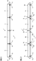
- FIG 1 shows an S-Bru articulated train 1 according to the invention with four tension members 2a, 2b, 2c, 2d.
- a first tension member 2a and a (in FIG 1 right next to it) second tension member 2b are based on a first common bogie 3a.
- the second tension member 2b and a (in FIG 1 right next to it) third tension member 2c are based on a second common bogie 3b.
- the third tension member 2c and a (in FIG 1 fourth tension member 2d (arranged to the right) are supported on a third common bogie 3c.
- the bogies 3a, 3b, 3c are also referred to as Jakobs bogies.
- the first tension member 2a (in FIG 1 arranged on the outside left) is supported on a first end face 4a of the articulated train 1 on a first separate bogie 5a.
- the fourth tension member 2d (in FIG 1 arranged on the outside right) is supported on a second end face 4b of the articulated train 1 on a second separate bogie 5b.
- Each bogie 3a, 3b, 3c, 5a, 5b includes a pair of wheelsets. Each set of wheels comprises two wheels located opposite one another, which can be moved along a rail (shown).
- Each bogie 3a, 3b, 3c, 5a, 5b therefore includes four wheels.
- Bogies/running gears 3a, 3b, 3c, 5a, 5b can also be provided within the scope of the invention, each of which has more or fewer wheels or wheel sets.
- a drive system 6 of the articulated train 1 includes asynchronous motors and/or reluctance motors 7a, 7b, which are arranged in a region of the two separate bogies 5a, 5b of the first and fourth traction element 2a, 2d and drive the associated wheels.
- the drive system 6 of the articulated train 1 comprises permanent-magnet motors 7c, 7d, which are installed in an area of the first common bogie 3a between the first tension member 2a and the second tension member 2b, and in an area of the third common bogie 3c between the third tension member 2c and the fourth tension member 2d are arranged. No drive motor is arranged in the second common bogie 3b.
- FIG 2 shows a first variant of a regional train 1 according to the invention with four cars 8a, 8b, 8c, 8d.
- the first carriage 8a (in FIG 2 far left) and the fourth carriage 8d represent conventional carriages, while the second carriage 8b and the third carriage 8c, which are located between the first carriage 8a and the fourth carriage 8d, are designed as double-deck middle carriages 8b, 8c.
- the second carriage 8b and the third carriage 8c can also be used as conventional wagons (no double-decker version).
- All four carriages 8a, 8b, 8c, 8d are each supported in their end regions 9a, 9b, 9c, 9d, 9e, 9f, 9g, 9h on a bogie 10a, 10b, 10c, 10d, 10e, 10f, 10g, 10h .
- Each bogie 10a, 10b, 10c, 10d, 10e, 10f, 10g, 10h includes a pair of wheelsets. Each set of wheels comprises two wheels located opposite one another, which can be moved along a rail (shown).
- Each bogie 10a, 10b, 10c, 10d, 10e, 10f, 10g, 10h therefore includes four wheels.
- Bogies/carriages 10a, 10b, 10c, 10d, 10e, 10f, 10g, 10h can also be provided within the scope of the invention, each of which has more or fewer wheels or wheel sets.
- a drive system 6 of the regional train 1 comprises permanent-magnet motors 11a, 11b, 11c, 11d, which are arranged in a region of the bogies 10a, 10b, 10g, 10h of the first carriage 8a and the fourth carriage 8d.
- the drive system 6 of the regional train 1 also includes asynchronous motors and/or reluctance motors 11e, 11f, which are installed in a (in FIG 2 left) end area 9c of the second carriage 8b and in a (in FIG 2 located on the right) end region 9f of the third carriage 8c are arranged in a region of the associated bogies 10c, 10f and drive the associated wheels.
- FIG 3 shows a second variant of a regional train 1 according to the invention with four cars 8a, 8b, 8c, 8d.
- the first carriage 8a (in FIG 2 far left) and the fourth car 8d represent conventional carriages, while the second carriage 8c and the third carriage 8c, which are located between the first carriage 8a and the fourth carriage 8d, are designed as double-deck middle carriages 8b, 8c.
- the second carriage 8b and the third carriage 8c can also be in the form of conventional carriages (not a double-decker version).
- All four carriages 8a, 8b, 8c, 8d are each supported in their end regions 9a, 9b, 9c, 9d, 9e, 9f, 9g, 9h on a bogie 10a, 10b, 10c, 10d, 10e, 10f, 10g, 10h .
- Each bogie 10a, 10b, 10c, 10d, 10e, 10f, 10g, 10h includes a pair of wheelsets. Each set of wheels comprises two wheels located opposite one another, which can be moved along a rail (shown).
- Each bogie 10a, 10b, 10c, 10d, 10e, 10f, 10g, 10h therefore includes four wheels.
- Bogies/carriages 10a, 10b, 10c, 10d, 10e, 10f, 10g, 10h can also be provided within the scope of the invention, each of which has more or fewer wheels or wheel sets.
- a drive system 6 of the regional train 1 comprises permanent-magnet motors 12a, 12b, which are installed in an area of (in 3 left) bogie 10a of the first car 8a and in an area of the (in 3 located on the right) bogie 10h of the fourth car 8d are arranged.
- the drive system 6 of the regional train 1 also includes asynchronous motors and/or reluctance motors 12c, 12d, which are installed in a (in FIG 2 right) end area 9b of the first carriage 8a and in a (in FIG 2 left) end region 9g of the fourth car 8d are arranged in a region of the associated bogies 10b, 10g and drive the associated wheels.
- the second carriage 8b and the third carriage 8c have no drive motors.
- FIG 4 shows a freight locomotive according to the invention 1.
- the goods train locomotive 1 is supported on a first end face 13a on a first bogie 14a. On a second end face 13b, it is supported on a second bogie 14b.
- Each bogie 14a, 14b includes three wheel sets. Each set of wheels comprises two wheels located opposite one another, which can be moved along a rail (shown). Each bogie 14a, 14b therefore includes six wheels. Within the scope of the invention, bogies 14a, 14b can also be provided, which each have more or fewer wheels or sets of wheels.
- a drive system 6 of the freight locomotive 1 includes asynchronous motors and/or reluctance motors 15a, 15b, which each drive a central wheel set of the two bogies 14a, 14b.
- the drive system 6 of the freight locomotive 1 also includes permanent-magnet motors 15c, 15d, which drive the other wheel sets of the two bogies 14a, 14b.
Landscapes
- Engineering & Computer Science (AREA)
- Mechanical Engineering (AREA)
- Transportation (AREA)
- Power Engineering (AREA)
- Life Sciences & Earth Sciences (AREA)
- Sustainable Development (AREA)
- Sustainable Energy (AREA)
- Control Of Multiple Motors (AREA)
- Electric Propulsion And Braking For Vehicles (AREA)
- Automatic Cycles, And Cycles In General (AREA)
- Platform Screen Doors And Railroad Systems (AREA)
- Machines For Laying And Maintaining Railways (AREA)
Description
- Die Erfindung betrifft ein Schienenfahrzeug mit einem Antriebssystem mit einer Mehrzahl an Antriebsmotoren nach Anspruch 1.
- Zur Realisierung eines Antriebs für Schienenfahrzeuge ist es bekannt, permanentmagneterregte Traktionsmotoren (PM-Motoren), Synchron-Reluktanzmaschinen oder Asynchronmaschinen zu verwenden. PM-Traktionsmotoren sind allgemein energieeffizienter als Asynchronmaschinen, da bei nahezu identischen Ständerverlusten beider Maschinen Rotorverluste bei den PM-Traktionsmotoren nahezu komplett entfallen. Die Rotorverluste tragen dabei in etwa mit 25 bis 30 Prozentpunkten zu den Gesamtverlusten der Asynchronmaschinen bei.
- Beim Betrieb von Schienenfahrzeugen, insbesondere bei Nahverkehrs- und Regionalverkehrszügen, untergliedert man Bewegungsphasen zwischen zwei Stationen in vier Bewegungsabschnitte: Beschleunigung, Beharrung, Rollen/ Auslauf und Bremsung.
- Der Beschleunigungsbereich ist von einer Antriebsleistung des Schienenfahrzeugs und einer Übertragung der Antriebskräfte auf die Räder des Schienenfahrzeugs geprägt. Solange eine Zugkraft des Antriebs des Schienenfahrzeugs größer ist als ein ihm entgegengebrachter Fahrwiderstand, beschleunigt das Schienenfahrzeug. Der Beharrungsabschnitt wird erreicht, wenn sich Zugkraft und Fahrwiderstand (genauer: Fahrwiderstandskraft) entsprechen (mit entgegengesetzten Vorzeichen).
- In einer Rollphase bzw. in dem Auslaufabschnitt wird die Zugkraft soweit zurückgenommen, dass das Schienenfahrzeug aufgrund des Fahrwiderstands seine Fahrgeschwindigkeit verringert. Werden zusätzlich Bremskräfte eingesetzt, so geht der Auslaufabschnitt in den Abschnitt der Bremsung über.
- Das Zusammenspiel der zuvor genannten Abschnitte bzw. Phasen einer Fahrt des Schienenfahrzeugs wird auch als Fahrspiel bezeichnet.
- In den Fahrspielen zwischen den einzelnen Stationen kommt es in den Phasen der Beharrung, des Rollens/Auslaufs und der Bremsung für den oder die Antriebsmotoren zu einem Teillastbetrieb oder sogar zu antriebslosen Rollphasen. Dabei erfolgt ein Betrieb mit 0 bis 50 Prozentpunkten der fahrzeugseitig installierten Gesamtantriebsleistung über einen verhältnismäßig großen Zeitanteil der Gesamtfahrdauer zwischen zwei Stationen. Aus den Stationen heraus wird aber in der Phase der Beschleunigung eine hohe Zugkraft und Antriebsleistung benötigt. Diese hohe Zugkraft und Antriebsleistung bestimmen die Gesamtzahl an angetriebenen Radsätzen und der installierten (Kurzzeit-)Antriebsleistung. Diese hohe Antriebsleistung wird aber während der übrigen Phasen der Fahrspiele bis auf etwaiges regeneratives Bremsen nicht mehr benötigt.
- Bei einer Verwendung von Asynchronmaschinen als Antriebsmotoren können mittels Taktsperren einzelner Stromrichter, die die Motoren mit elektrischer Leistung versorgen, einzelne Antriebsmotoren und damit angetriebene Radsätze abgeschaltet werden. In den abgeschalteten Asynchronmaschinen treten dabei keine elektromagnetischen Verluste mehr auf. Die Stromrichtertaktsperre vermeidet dabei auch Verluste in den verwendeten Leistungshalbleitern (Schalt- und Durchlassverluste im Teillastbetrieb). Die verbliebenen aktiven Antriebsmotoren werden nahe einem Vollastpunkt betrieben, wodurch sich höhere Wirkungsgrade erzielen lassen.
- Eine Taktsperre ist bei PM-Motoren nicht möglich oder führt zumindest nicht zu einer elektromagnetisch verlustlosen Maschine (bei kleiner Ständerwindungszahl mit geringer induzierter Leerlaufspannung und nahezu keiner Feldschwächung), da der rotierende Permanentmagnetfluss weiterhin Wirbelstrom- und Hystereseverluste in dem in der Maschine verwendeten Eisenkern hervorruft.
- Aus genannten Gründen ergibt ein Vergleich des Energieverbrauchs zwischen Asynchronmaschinen und PM- Motoren in Fahrspielen mit langen Roll- oder Auslaufphasen, dass die PM- Motoren keine Energieeinsparung erzielen können oder sogar eine schlechtere Energiebilanz erzielen. Bei einer reinen Verwendung von Asynchronmaschinen treten jedoch die zuvor erwähnten Verluste in den Rotoren der Maschinen auf.
- Aus der
JP 2005 073314 A - Der Erfindung liegt die Aufgabe zugrunde, ein Schienenfahrzeug mit einem Antriebssystem bereitzustellen, die die zuvor genannten Nachteile überwindet und eine höhere Energieeffizienz aufweist.
- Diese Aufgabe wird gelöst durch ein Schienenfahrzeug mit den Merkmalen des Patentanspruchs 1.
- Vorteilhafte Weiterbildungen ergeben sich aus den abhängigen Patentansprüchen.
- Das erfindungsgemäße Schienenfahrzeug weist Radsätze auf, die jeweils zwei gegenüberliegend angeordnete Räder umfassen, die wenigstens teilweise von einem Antriebssystem mit einer Mehrzahl an Antriebsmotoren angetrieben werden, wobei das Antriebssystem wenigstens einen permanentmagneterregten Motor und wenigstens einen Asynchronmotor und/oder wenigstens einen Reluktanzmotor als Antriebsmotoren umfasst. Kennzeichnend ist eine Anzahl an Radsätzen, die von einem oder mehreren permanentmagneterregten Motoren angetrieben werden, doppelt so groß ist wie eine Anzahl an Radsätzen, die von einem oder mehreren Asynchronmotoren und/oder Reluktanzmotoren angetrieben werden, oder ist eine Anzahl an Radsätzen, die von einem oder mehreren permanentmagneterregten Motoren angetrieben werden, identisch ist mit einer Anzahl an Radsätzen, die von einem oder mehreren Asynchronmotoren und/oder Reluktanzmotoren angetrieben werden.
- Bei dem Schienenfahrzeug kann es sich beispielsweise um einen Nahverkehrs- oder Regionalverkehrszug oder um eine Personen- oder Güterzuglokomotive handeln.
- Bei einem Teillastbetrieb des anzutreibenden Schienenfahrzeug kann das erfindungsgemäße Antriebssystem vorteilhafterweise die in diesem Lastbereich verlustbehafteteren Asynchron- und/oder Reluktanzmotoren abschalten. Die Permanentmagneterregung erlaubt im Gegensatz zu dem Asynchronmotor oder dem Reluktanzmotor auch in geringeren Leistungsbereichen hohe Wirkungsgrade und Leistungsfaktoren oder kann mit einer hohen Last betrieben werden (je nach Anteil der Maschinentypen und der erforderlichen Gesamtantriebsleistung).
- Durch die Kombination aus permanentmagneterregten Motoren mit Asynchronmotoren und/oder Reluktanzmotoren als Antriebsmotoren lassen sich für Spitzenlastbereiche während der Beschleunigungsphase die Asynchronmotoren und/oder Reluktanzmotoren zusätzlich zu den permanentmagneterregten Motoren zuschalten, um eine maximale Zugkraft und Antriebsleistung zu ermöglichen.
- Die Erfindung ermöglicht es daher, die Vorteile von permanentmagneterregten Motoren (hoher Wirkungsgrad auch im Teillastbetrieb) und von Asynchronmotoren und/oder Reluktanzmotoren (einfache verlustfreie Abschaltbarkeit) zu kombinieren und ein energieverbraucheffizientes Antriebssystem bereitzustellen.
- Bevorzugt weist die Mehrzahl an Antriebsmotoren des Antriebssystems im Wesentlichen gleiche Ständerelemente auf. Beispielsweise kann ein sechspoliger Fahrmotorständer für die Antriebsmotoren vorgesehen sein, der jeweils entsprechend mit einem zu einem permanentmagneterregten Motor gehörigen Rotor, einem für einen Asynchronmotor ausgelegten Käfigrotor oder mit einem Läufer für einen Reluktanzmotor kombiniert ist. Dadurch lässt sich eine Instandhaltung des Antriebssystems besonders einfach und kostengünstig gestalten.
- Ist ein permanenterregter Motor in Kombination mit einem als Synchron-Reluktanzmotor ausgebildeten Reluktanzmotor für das Antriebssystem vorgesehen, können eine im Wesentlichen gleiche Stromrichtertopologie und Antriebsregelung zur Ansteuerung der beiden Motortypen verwendet werden, was den Betrieb und die Wartung/Instandhaltung des Antriebssystems weiter vereinfacht. Ein Synchron-Reluktanzmotor ist dabei ein Drehstrom-Synchronmotor mit einem Rotor (Läufer), der entweder einen sogenannten Flusssperrenschnitt oder ausgeprägte Pole aufweist.
- Erfindungsgemäß ist eine Anzahl an Radsätzen, die von einem permanentmagneterregten Motor angetrieben werden, doppelt so groß ist wie eine Anzahl an Radsätzen, die von einem Asynchronmotor und/oder einem Reluktanzmotor angetrieben werden.
- Alternativ ist eine Anzahl an Radsätzen, die von einem permanentmagneterregten Motor angetrieben werden, erfindungsgemäß genau so groß wie eine Anzahl an Radsätzen, die von einem Asynchronmotor und/oder einem Reluktanzmotor angetrieben werden. Mit anderen Worten ist die Anzahl an Radsätzen, die von einem permanentmagneterregten Motor angetrieben werden, identisch mit der Anzahl an Radsätzen, die von einem Asynchronmotor und/oder einem Reluktanzmotor angetrieben werden.
- Die oben beschriebenen Eigenschaften, Merkmale und Vorteile dieser Erfindung sowie die Art und Weise, wie diese erreicht werden, werden klarer und deutlicher verständlich im Zusammenhang mit der folgenden Beschreibung der Ausführungsbeispiele, die im Zusammenhang mit den Zeichnungen näher erläutert werden. Es zeigen:
- FIG 1
- einen S-Bahn Gliederzug mit Jakobsgestellen in einer Seitenansicht;
- FIG 2
- einen Regionalzug mit Doppelstock-Mittelwagen gemäß einer ersten Variante in einer Seitenansicht;
- FIG 3
- einen Regionalzug mit Doppelstock-Mittelwagen gemäß einer zweiten Variante in einer Seitenansicht; und
- FIG 4
- eine Güterzuglokomotive in einer Seitenansicht.
-
FIG 1 zeigt einen erfindungsgemäßen S-Bahn Gliederzug 1 mit vier Zuggliedern 2a, 2b, 2c, 2d. Ein erstes Zugglied 2a und ein (inFIG 1 rechts daneben angeordnetes) zweites Zugglied 2b stützen sich auf ein erstes gemeinsames Drehgestell 3a ab. Das zweite Zugglied 2b und ein (inFIG 1 rechts daneben angeordnetes) drittes Zugglied 2c stützen sich auf ein zweites gemeinsames Drehgestell 3b ab. Das dritte Zugglied 2c und ein (inFIG 1 rechts daneben angeordnetes) viertes Zugglied 2d stützen sich auf ein drittes gemeinsames Drehgestell 3c ab. Die Drehgestelle 3a, 3b, 3c werden auch als Jakobsdrehgestelle bezeichnet. - Das erste Zugglied 2a (in
FIG 1 links außen angeordnet) stützt sich an einer ersten Stirnseite 4a des Gliederzugs 1 auf ein erstes separates Drehgestell 5a ab. Das vierte Zugglied 2d (inFIG 1 rechts außen angeordnet) stützt sich an einer zweiten Stirnseite 4b des Gliederzugs 1 auf ein zweites separates Drehgestell 5b ab. Jedes Drehgestell 3a, 3b, 3c, 5a, 5b umfasst ein Paar Radsätze. Dabei umfasst jeder Radsatz zwei einander gegenüberliegende Räder, die auf einer Schiene (dargestellt) entlang bewegt werden können. Jedes Drehgestell 3a, 3b, 3c, 5a, 5b umfasst demnach vier Räder. Es sind im Rahmen der Erfindung auch Drehgestelle/Fahrwerke 3a, 3b, 3c, 5a, 5b vorsehbar, die jeweils mehr oder weniger Räder bzw. Radsätze aufweisen. - Ein Antriebssystem 6 des Gliederzugs 1 umfasst Asynchronmotoren und/oder Reluktanzmotoren 7a, 7b, die in einem Bereich der beiden separaten Drehgestelle 5a, 5b des ersten bzw. vierten Zugglieds 2a, 2d angeordnet sind und die dazugehörigen Räder antreiben.
- Weiterhin umfasst das Antriebssystem 6 des Gliederzugs 1 permanentmagneterregte Motoren 7c, 7d, die in einem Bereich des ersten gemeinsamen Drehgestells 3a zwischen dem ersten Zugglied 2a und dem zweiten Zugglied 2b, und in einem Bereich des dritten gemeinsamen Drehgestells 3c zwischen dem dritten Zugglied 2c und dem vierten Zugglied 2d angeordnet sind. Im zweiten gemeinsamen Drehgestell 3b ist kein Antriebsmotor angeordnet.
-
FIG 2 zeigt eine erste Variante eines erfindungsgemäßen Regionalzugs 1 mit vier Wagen 8a, 8b, 8c, 8d. Der erste Wagen 8a (inFIG 2 links außen) und der vierte Wagen 8d stellen konventionelle Wagen dar, während der zweite Wagen 8b und der dritte Wagen 8c, die sich zwischen dem ersten Wagen 8a und dem vierten Wagen 8d befinden, als Doppelstock-Mittelwagen 8b, 8c ausgebildet sind. Der zweite Wagen 8b und der dritte Wagen 8c können auch als konventionelle Wagen (keine Doppelstock-Ausführung) ausgebildet sein. - Alle vier Wagen 8a, 8b, 8c, 8d stützen sich jeweils in ihren Endbereichen 9a, 9b, 9c, 9d, 9e, 9f, 9g, 9h auf ein Drehgestell 10a, 10b, 10c, 10d, 10e, 10f, 10g, 10h ab. Jedes Drehgestell 10a, 10b, 10c, 10d, 10e, 10f, 10g, 10h umfasst ein Paar Radsätze. Dabei umfasst jeder Radsatz zwei einander gegenüberliegende Räder, die auf einer Schiene (dargestellt) entlang bewegt werden können. Jedes Drehgestell 10a, 10b, 10c, 10d, 10e, 10f, 10g, 10h umfasst demnach vier Räder. Es sind im Rahmen der Erfindung auch Drehgestelle/Fahrwerke 10a, 10b, 10c, 10d, 10e, 10f, 10g, 10h vorsehbar, die jeweils mehr oder weniger Räder bzw. Radsätze aufweisen.
- Ein Antriebssystem 6 des Regionalzugs 1 umfasst permanentmagneterregte Motoren 11a, 11b, 11c, 11d, die in einem Bereich der Drehgestelle 10a, 10b, 10g, 10h des ersten Wagens 8a und des vierten Wagens 8d angeordnet sind.
- Das Antriebssystem 6 des Regionalzugs 1 umfasst zudem Asynchronmotoren und/oder Reluktanzmotoren 11e, 11f, die in einem (in
FIG 2 links befindlichen) Endbereich 9c des zweiten Wagens 8b und in einem (inFIG 2 rechts befindlichen) Endbereich 9f des dritten Wagens 8c in einem Bereich der dazugehörigen Drehgestelle 10c, 10f angeordnet sind und die dazugehörigen Räder antreiben. - In einem (in
FIG 2 rechts befindlichen) Endbereich 9d des zweiten Wagens 8b und in einem (inFIG 2 links befindlichen) Endbereich 9e des dritten Wagens 8c in einem Bereich der dazugehörigen Drehgestelle 10d, 10e ist kein Antriebsmotor angeordnet. -
FIG 3 zeigt eine zweite Variante eines erfindungsgemäßen Regionalzugs 1 mit vier Wagen 8a, 8b, 8c, 8d. Der erste Wagen 8a (inFIG 2 links außen) und der vierte Wagen 8d stellen konventionelle Wagen dar, während der zweite Wagen 8c und der dritte Wagen 8c, die sich zwischen dem ersten Wagen 8a und dem vierten Wagen 8d befinden, als Doppelstock-Mittelwagen 8b, 8c ausgebildet sind. Der zweite Wagen 8b und der dritte Wagen 8c können auch als konventionelle Wagen (keine Doppelstock-Ausführung) ausgebildet sein. - Alle vier Wagen 8a, 8b, 8c, 8d stützen sich jeweils in ihren Endbereichen 9a, 9b, 9c, 9d, 9e, 9f, 9g, 9h auf ein Drehgestell 10a, 10b, 10c, 10d, 10e, 10f, 10g, 10h ab. Jedes Drehgestell 10a, 10b, 10c, 10d, 10e, 10f, 10g, 10h umfasst ein Paar Radsätze. Dabei umfasst jeder Radsatz zwei einander gegenüberliegende Räder, die auf einer Schiene (dargestellt) entlang bewegt werden können. Jedes Drehgestell 10a, 10b, 10c, 10d, 10e, 10f, 10g, 10h umfasst demnach vier Räder. Es sind im Rahmen der Erfindung auch Drehgestelle/Fahrwerke 10a, 10b, 10c, 10d, 10e, 10f, 10g, 10h vorsehbar, die jeweils mehr oder weniger Räder bzw. Radsätze aufweisen.
- Ein Antriebssystem 6 des Regionalzugs 1 umfasst permanentmagneterregte Motoren 12a, 12b, die in einem Bereich des (in
FIG 3 links befindlichen) Drehgestells 10a des ersten Wagens 8a und in einem Bereich des (inFIG 3 rechts befindlichen) Drehgestells 10h des vierten Wagens 8d angeordnet sind. - Das Antriebssystem 6 des Regionalzugs 1 umfasst zudem Asynchronmotoren und/oder Reluktanzmotoren 12c, 12d, die in einem (in
FIG 2 rechts befindlichen) Endbereich 9b des ersten Wagens 8a und in einem (inFIG 2 links befindlichen) Endbereich 9g des vierten Wagens 8d in einem Bereich der dazugehörigen Drehgestelle 10b, 10g angeordnet sind und die dazugehörigen Räder antreiben. - Der zweite Wagen 8b und der dritte Wagen 8c weisen keine Antriebsmotoren auf.
-
FIG 4 zeigt eine erfindungsgemäße Güterzuglokomotive 1. - Die Güterzuglokomotive 1 stützt sich an einer ersten Stirnseite 13a auf ein erstes Drehgestell 14a ab. An einer zweiten Stirnseite 13b stützt sie sich auf ein zweites Drehgestell 14b ab.
- Jedes Drehgestell 14a, 14b umfasst drei Radsätze. Dabei umfasst jeder Radsatz zwei einander gegenüberliegende Räder, die auf einer Schiene (dargestellt) entlang bewegt werden können. Jedes Drehgestell 14a, 14b umfasst demnach sechs Räder. Es sind im Rahmen der Erfindung auch Drehgestelle 14a, 14b vorsehbar, die jeweils mehr oder weniger Räder bzw. Radsätze aufweisen.
- Ein Antriebssystem 6 der Güterzuglokomotive 1 umfasst Asynchronmotoren und/oder Reluktanzmotoren 15a, 15b, die jeweils einen mittleren Radsatz der beiden Drehgestelle 14a, 14b antreiben.
- Das Antriebssystem 6 der Güterzuglokomotive 1 umfasst zudem permanentmagneterregte Motoren 15c, 15d, die die übrigen Radsätze der beiden Drehgestelle 14a, 14b antreiben.
- Obwohl die Erfindung im Detail durch das bevorzugte Ausführungsbeispiel näher illustriert und beschrieben wurde, so ist die Erfindung nicht durch die offenbarten Beispiele eingeschränkt und andere Variationen im Rahmen der Ansprüche können vom Fachmann hieraus abgeleitet werden, ohne den Schutzumfang der Erfindung zu verlassen.
Claims (3)
- Schienenfahrzeug (1) mit Radsätzen, die jeweils zwei gegenüberliegend angeordnete Räder umfassen, die wenigstens teilweise von einem Antriebssystem (6) mit einer Mehrzahl an Antriebsmotoren (7a, 7b, 7c, 7d, 11a, 11b, 11c, 11d, 11e, 11f, 12a, 12b, 12c, 12d, 15a, 15b, 15c, 15d) angetrieben werden, wobeidas Antriebsystem (6) wenigstens einen permanentmagneterregten Motor (7c, 7d, 11a, 11b, 11c, 11d, 12a, 12b, 15c, 15d) und wenigstens einen Asynchronmotor und/oder wenigstens einen Reluktanzmotor (7a, 7b, 11e, 11f, 12c, 12d, 15a, 15b) als Antriebsmotoren (7a, 7b, 7c, 7d, 11a, 11b, 11c, 11d, 11e, 11f, 12a, 12b, 12c, 12d, 15a, 15b, 15c, 15d) umfasst,dadurch gekennzeichnet, dasseine Anzahl an Radsätzen, die von einem oder mehreren permanentmagneterregten Motoren (7c, 7d, 11a, 11b, 11c, 11d, 12a, 12b, 15c, 15d) angetrieben werden, doppelt so groß ist wie eine Anzahl an Radsätzen, die von einem oder mehreren Asynchronmotoren und/oder Reluktanzmotoren (7a, 7b, 11e, 11f, 12c, 12d, 15a, 15b) angetrieben werden, odereine Anzahl an Radsätzen, die von einem oder mehreren permanentmagneterregten Motoren (7c, 7d, 11a, 11b, 11c, 11d, 12a, 12b, 15c, 15d) angetrieben werden, identisch ist mit einer Anzahl an Radsätzen, die von einem oder mehreren Asynchronmotoren und/oder Reluktanzmotoren (7a, 7b, 11e, 11f, 12c, 12d, 15a, 15b) angetrieben werden.
- Schienenfahrzeug (1) nach Anspruch 1, bei dem die Mehrzahl an Antriebsmotoren (7a, 7b, 7c, 7d, 11a, 11b, 11c, 11d, 11e, 11f, 12a, 12b, 12c, 12d, 15a, 15b, 15c, 15d) im Wesentlichen gleiche Ständerelemente aufweist.
- Schienenfahrzeug (1) nach Anspruch 1 oder 2, das wenigstens einen permanenterregten Motor (7c, 7d, 11a, 11b, 11c, 11d, 12a, 12b, 15c, 15d) und einen als Synchron-Reluktanzmotor ausgebildeten Reluktanzmotor (7a, 7b, 11e, 11f, 12c, 12d, 15a, 15b) umfasst.
Priority Applications (4)
| Application Number | Priority Date | Filing Date | Title |
|---|---|---|---|
| EP18170391.9A EP3564088B1 (de) | 2018-05-02 | 2018-05-02 | Schienenfahrzeug mit einem anstriebssystem |
| ES18170391T ES2921062T3 (es) | 2018-05-02 | 2018-05-02 | Vehículo ferroviario con un sistema de accionamiento |
| CN201910353778.3A CN110435679A (zh) | 2018-05-02 | 2019-04-29 | 用于轨道车辆的驱动系统 |
| US16/401,321 US11214149B2 (en) | 2018-05-02 | 2019-05-02 | Rail vehicle and drive system for a rail vehicle |
Applications Claiming Priority (1)
| Application Number | Priority Date | Filing Date | Title |
|---|---|---|---|
| EP18170391.9A EP3564088B1 (de) | 2018-05-02 | 2018-05-02 | Schienenfahrzeug mit einem anstriebssystem |
Publications (2)
| Publication Number | Publication Date |
|---|---|
| EP3564088A1 EP3564088A1 (de) | 2019-11-06 |
| EP3564088B1 true EP3564088B1 (de) | 2022-04-06 |
Family
ID=62116698
Family Applications (1)
| Application Number | Title | Priority Date | Filing Date |
|---|---|---|---|
| EP18170391.9A Active EP3564088B1 (de) | 2018-05-02 | 2018-05-02 | Schienenfahrzeug mit einem anstriebssystem |
Country Status (4)
| Country | Link |
|---|---|
| US (1) | US11214149B2 (de) |
| EP (1) | EP3564088B1 (de) |
| CN (1) | CN110435679A (de) |
| ES (1) | ES2921062T3 (de) |
Families Citing this family (6)
| Publication number | Priority date | Publication date | Assignee | Title |
|---|---|---|---|---|
| US10279823B2 (en) * | 2016-08-08 | 2019-05-07 | General Electric Company | System for controlling or monitoring a vehicle system along a route |
| EP3502811A1 (de) * | 2017-12-21 | 2019-06-26 | Siemens Aktiengesellschaft | Antriebssteuerung mit eigenständiger fehlerkorrektur von lagefehlern |
| DE102021208388A1 (de) | 2021-08-03 | 2023-02-09 | Siemens Mobility GmbH | Antriebssystem für ein Schienenfahrzeug |
| JP2025525462A (ja) | 2022-06-27 | 2025-08-05 | アントロポセン・インスティテュート・エルエルシー | 軸方向磁束スイッチリラクタンスおよびインダクタンス状態機械システム、デバイス、および方法 |
| US12149134B2 (en) | 2022-06-27 | 2024-11-19 | Anthropocene Institute LLC | Axial flux switched reluctance motor and generator, and related systems and methods |
| DE102022206679A1 (de) | 2022-06-30 | 2024-01-04 | Siemens Mobility GmbH | Elektrisches Antriebssystem |
Family Cites Families (14)
| Publication number | Priority date | Publication date | Assignee | Title |
|---|---|---|---|---|
| JP2000245005A (ja) | 1999-02-18 | 2000-09-08 | Toshiba Corp | 車両駆動制御装置 |
| JP3999172B2 (ja) * | 2003-08-27 | 2007-10-31 | 財団法人鉄道総合技術研究所 | 鉄道車両用非常用電気ブレーキ装置 |
| JP4742992B2 (ja) * | 2006-05-30 | 2011-08-10 | トヨタ自動車株式会社 | 動力出力装置およびそれを備えた車両 |
| US20080121136A1 (en) * | 2006-11-28 | 2008-05-29 | General Electric Company | Hybrid locomotive and method of operating the same |
| US20080148993A1 (en) * | 2006-12-08 | 2008-06-26 | Tom Mack | Hybrid propulsion system and method |
| CN102039899B (zh) * | 2009-10-12 | 2013-02-06 | 梅长江 | 连续运输式城市轨道交通系统 |
| EP2883775A1 (de) * | 2013-12-13 | 2015-06-17 | Siemens Aktiengesellschaft | Drehgestell mit auf den Lagerungen gelagertem Radsatzantrieb |
| JP6187268B2 (ja) * | 2014-01-10 | 2017-08-30 | トヨタ自動車株式会社 | 電動車両 |
| CN103770637B (zh) * | 2014-01-23 | 2016-04-27 | 长安大学 | 一种全液压驱动的矿用自卸车 |
| CN205075633U (zh) * | 2015-09-27 | 2016-03-09 | 张峰 | 一种用于电动车辆的双动力电机 |
| NL2016655B1 (nl) * | 2016-04-21 | 2017-11-15 | Trs Transp B V | Treinwagon voorzien van een inductiegenerator. |
| US9789871B1 (en) * | 2016-08-05 | 2017-10-17 | Atieva, Inc. | High efficiency, high power density drive system utilizing complementary motor assemblies |
| CN206156268U (zh) * | 2016-09-19 | 2017-05-10 | 珠海格力电器股份有限公司 | 一种测试系统 |
| JP6762825B2 (ja) * | 2016-09-26 | 2020-09-30 | 株式会社東芝 | 電動機制御装置およびドライブシステム |
-
2018
- 2018-05-02 ES ES18170391T patent/ES2921062T3/es active Active
- 2018-05-02 EP EP18170391.9A patent/EP3564088B1/de active Active
-
2019
- 2019-04-29 CN CN201910353778.3A patent/CN110435679A/zh active Pending
- 2019-05-02 US US16/401,321 patent/US11214149B2/en active Active
Also Published As
| Publication number | Publication date |
|---|---|
| CN110435679A (zh) | 2019-11-12 |
| US11214149B2 (en) | 2022-01-04 |
| ES2921062T3 (es) | 2022-08-17 |
| US20190337390A1 (en) | 2019-11-07 |
| EP3564088A1 (de) | 2019-11-06 |
Similar Documents
| Publication | Publication Date | Title |
|---|---|---|
| EP3564088B1 (de) | Schienenfahrzeug mit einem anstriebssystem | |
| EP3224929B1 (de) | Permanenterregte synchronmaschine und kraftfahrzeugsystem | |
| EP3038233B1 (de) | Permanentmagnet-synchronmotor und elektrische servolenkung | |
| EP2054991A1 (de) | Stator für einen elektrischen antriebsmotor | |
| DE102007040750A1 (de) | Stromerregter Synchronmotor insbesondere für Fahrzeugantriebe | |
| EP3019366B1 (de) | Vorladeschaltkreis für eine mehrsystem-stromrichteranordnung | |
| DE10046729A1 (de) | Elektrische Maschine sowie Elektrisches System | |
| EP4129744A1 (de) | Antriebssystem für ein schienenfahrzeug | |
| WO2014180637A2 (de) | Elektrische maschine, insbesondere für eine lenkhilfe eines kraftfahrzeugs | |
| DE102022206679A1 (de) | Elektrisches Antriebssystem | |
| WO2006131210A1 (de) | Elektrische antriebseinrichtung | |
| DE3234673A1 (de) | Drehstrommotor | |
| DE102016204118A1 (de) | Rotierende elektrische Maschine | |
| DE10053265C2 (de) | Feststellbremseinrichtung an Fahrzeugen und Antriebssystem mit einer Feststellbremseinrichtung | |
| DE102014226570A1 (de) | Asynchronmaschine für sicherheitsrelevante Einsatzgebiete | |
| DE4314513A1 (de) | Transversalflußmaschinen mit kombinierter PM-Erregung | |
| WO2020177964A1 (de) | Rotor für eine permanenterregte elektrische maschine mit stützstruktur | |
| EP4335685A1 (de) | Elektrisches antriebssystem | |
| DE10110719C2 (de) | Transversalflußmaschine mit mehreren einsträngigen Erregerteilen | |
| DE10239853A1 (de) | Triebfahrwerk | |
| EP2667496A2 (de) | Einen elektrischen Pumpenmotor aufweisendes Flurförderzeug | |
| EP4300790A1 (de) | Elektrisches antriebssystem für ein schienenfahrzeug | |
| WO2018229113A1 (de) | Statoranordnung für einen elektromagnetischen linearantrieb | |
| WO2025228551A1 (de) | Elektrische maschine zum antrieb eines schienenfahrzeugs für den hochgeschwindigkeitsverkehr, fahrwerk mit einer solchen maschine und schienenfahrzeug | |
| EP4690441A1 (de) | Käfigrotor für eine elektrische asynchronmaschine, asynchronmaschine mit einem solchen käfigrotor sowie schienenfahrzeug mit einem als solche asynchronmaschine ausgebildeten traktionsantrieb |
Legal Events
| Date | Code | Title | Description |
|---|---|---|---|
| PUAI | Public reference made under article 153(3) epc to a published international application that has entered the european phase |
Free format text: ORIGINAL CODE: 0009012 |
|
| STAA | Information on the status of an ep patent application or granted ep patent |
Free format text: STATUS: THE APPLICATION HAS BEEN PUBLISHED |
|
| AK | Designated contracting states |
Kind code of ref document: A1 Designated state(s): AL AT BE BG CH CY CZ DE DK EE ES FI FR GB GR HR HU IE IS IT LI LT LU LV MC MK MT NL NO PL PT RO RS SE SI SK SM TR |
|
| AX | Request for extension of the european patent |
Extension state: BA ME |
|
| RAP1 | Party data changed (applicant data changed or rights of an application transferred) |
Owner name: SIEMENS MOBILITY GMBH |
|
| STAA | Information on the status of an ep patent application or granted ep patent |
Free format text: STATUS: REQUEST FOR EXAMINATION WAS MADE |
|
| 17P | Request for examination filed |
Effective date: 20200319 |
|
| RBV | Designated contracting states (corrected) |
Designated state(s): AL AT BE BG CH CY CZ DE DK EE ES FI FR GB GR HR HU IE IS IT LI LT LU LV MC MK MT NL NO PL PT RO RS SE SI SK SM TR |
|
| STAA | Information on the status of an ep patent application or granted ep patent |
Free format text: STATUS: EXAMINATION IS IN PROGRESS |
|
| 17Q | First examination report despatched |
Effective date: 20210610 |
|
| REG | Reference to a national code |
Ref country code: DE Ref legal event code: R079 Ref document number: 502018009301 Country of ref document: DE Free format text: PREVIOUS MAIN CLASS: B61C0003000000 Ipc: B60L0050000000 |
|
| GRAP | Despatch of communication of intention to grant a patent |
Free format text: ORIGINAL CODE: EPIDOSNIGR1 |
|
| STAA | Information on the status of an ep patent application or granted ep patent |
Free format text: STATUS: GRANT OF PATENT IS INTENDED |
|
| RIC1 | Information provided on ipc code assigned before grant |
Ipc: B61L 3/00 20060101ALI20211108BHEP Ipc: B61L 15/00 20060101ALI20211108BHEP Ipc: B61L 11/00 20060101ALI20211108BHEP Ipc: B61D 1/00 20060101ALI20211108BHEP Ipc: B61C 3/00 20060101ALI20211108BHEP Ipc: B60L 50/00 20190101AFI20211108BHEP |
|
| INTG | Intention to grant announced |
Effective date: 20211130 |
|
| GRAS | Grant fee paid |
Free format text: ORIGINAL CODE: EPIDOSNIGR3 |
|
| GRAA | (expected) grant |
Free format text: ORIGINAL CODE: 0009210 |
|
| STAA | Information on the status of an ep patent application or granted ep patent |
Free format text: STATUS: THE PATENT HAS BEEN GRANTED |
|
| AK | Designated contracting states |
Kind code of ref document: B1 Designated state(s): AL AT BE BG CH CY CZ DE DK EE ES FI FR GB GR HR HU IE IS IT LI LT LU LV MC MK MT NL NO PL PT RO RS SE SI SK SM TR |
|
| REG | Reference to a national code |
Ref country code: GB Ref legal event code: FG4D Free format text: NOT ENGLISH |
|
| REG | Reference to a national code |
Ref country code: CH Ref legal event code: EP |
|
| REG | Reference to a national code |
Ref country code: AT Ref legal event code: REF Ref document number: 1481034 Country of ref document: AT Kind code of ref document: T Effective date: 20220415 |
|
| REG | Reference to a national code |
Ref country code: IE Ref legal event code: FG4D Free format text: LANGUAGE OF EP DOCUMENT: GERMAN |
|
| REG | Reference to a national code |
Ref country code: DE Ref legal event code: R096 Ref document number: 502018009301 Country of ref document: DE |
|
| REG | Reference to a national code |
Ref country code: LT Ref legal event code: MG9D |
|
| REG | Reference to a national code |
Ref country code: NL Ref legal event code: MP Effective date: 20220406 |
|
| REG | Reference to a national code |
Ref country code: ES Ref legal event code: FG2A Ref document number: 2921062 Country of ref document: ES Kind code of ref document: T3 Effective date: 20220817 |
|
| PG25 | Lapsed in a contracting state [announced via postgrant information from national office to epo] |
Ref country code: NL Free format text: LAPSE BECAUSE OF FAILURE TO SUBMIT A TRANSLATION OF THE DESCRIPTION OR TO PAY THE FEE WITHIN THE PRESCRIBED TIME-LIMIT Effective date: 20220406 |
|
| PG25 | Lapsed in a contracting state [announced via postgrant information from national office to epo] |
Ref country code: SE Free format text: LAPSE BECAUSE OF FAILURE TO SUBMIT A TRANSLATION OF THE DESCRIPTION OR TO PAY THE FEE WITHIN THE PRESCRIBED TIME-LIMIT Effective date: 20220406 Ref country code: PT Free format text: LAPSE BECAUSE OF FAILURE TO SUBMIT A TRANSLATION OF THE DESCRIPTION OR TO PAY THE FEE WITHIN THE PRESCRIBED TIME-LIMIT Effective date: 20220808 Ref country code: NO Free format text: LAPSE BECAUSE OF FAILURE TO SUBMIT A TRANSLATION OF THE DESCRIPTION OR TO PAY THE FEE WITHIN THE PRESCRIBED TIME-LIMIT Effective date: 20220706 Ref country code: LT Free format text: LAPSE BECAUSE OF FAILURE TO SUBMIT A TRANSLATION OF THE DESCRIPTION OR TO PAY THE FEE WITHIN THE PRESCRIBED TIME-LIMIT Effective date: 20220406 Ref country code: HR Free format text: LAPSE BECAUSE OF FAILURE TO SUBMIT A TRANSLATION OF THE DESCRIPTION OR TO PAY THE FEE WITHIN THE PRESCRIBED TIME-LIMIT Effective date: 20220406 Ref country code: GR Free format text: LAPSE BECAUSE OF FAILURE TO SUBMIT A TRANSLATION OF THE DESCRIPTION OR TO PAY THE FEE WITHIN THE PRESCRIBED TIME-LIMIT Effective date: 20220707 Ref country code: FI Free format text: LAPSE BECAUSE OF FAILURE TO SUBMIT A TRANSLATION OF THE DESCRIPTION OR TO PAY THE FEE WITHIN THE PRESCRIBED TIME-LIMIT Effective date: 20220406 Ref country code: BG Free format text: LAPSE BECAUSE OF FAILURE TO SUBMIT A TRANSLATION OF THE DESCRIPTION OR TO PAY THE FEE WITHIN THE PRESCRIBED TIME-LIMIT Effective date: 20220706 |
|
| PG25 | Lapsed in a contracting state [announced via postgrant information from national office to epo] |
Ref country code: RS Free format text: LAPSE BECAUSE OF FAILURE TO SUBMIT A TRANSLATION OF THE DESCRIPTION OR TO PAY THE FEE WITHIN THE PRESCRIBED TIME-LIMIT Effective date: 20220406 Ref country code: PL Free format text: LAPSE BECAUSE OF FAILURE TO SUBMIT A TRANSLATION OF THE DESCRIPTION OR TO PAY THE FEE WITHIN THE PRESCRIBED TIME-LIMIT Effective date: 20220406 Ref country code: LV Free format text: LAPSE BECAUSE OF FAILURE TO SUBMIT A TRANSLATION OF THE DESCRIPTION OR TO PAY THE FEE WITHIN THE PRESCRIBED TIME-LIMIT Effective date: 20220406 Ref country code: IS Free format text: LAPSE BECAUSE OF FAILURE TO SUBMIT A TRANSLATION OF THE DESCRIPTION OR TO PAY THE FEE WITHIN THE PRESCRIBED TIME-LIMIT Effective date: 20220806 |
|
| REG | Reference to a national code |
Ref country code: DE Ref legal event code: R097 Ref document number: 502018009301 Country of ref document: DE |
|
| REG | Reference to a national code |
Ref country code: BE Ref legal event code: MM Effective date: 20220531 |
|
| PG25 | Lapsed in a contracting state [announced via postgrant information from national office to epo] |
Ref country code: SM Free format text: LAPSE BECAUSE OF FAILURE TO SUBMIT A TRANSLATION OF THE DESCRIPTION OR TO PAY THE FEE WITHIN THE PRESCRIBED TIME-LIMIT Effective date: 20220406 Ref country code: SK Free format text: LAPSE BECAUSE OF FAILURE TO SUBMIT A TRANSLATION OF THE DESCRIPTION OR TO PAY THE FEE WITHIN THE PRESCRIBED TIME-LIMIT Effective date: 20220406 Ref country code: RO Free format text: LAPSE BECAUSE OF FAILURE TO SUBMIT A TRANSLATION OF THE DESCRIPTION OR TO PAY THE FEE WITHIN THE PRESCRIBED TIME-LIMIT Effective date: 20220406 Ref country code: MC Free format text: LAPSE BECAUSE OF FAILURE TO SUBMIT A TRANSLATION OF THE DESCRIPTION OR TO PAY THE FEE WITHIN THE PRESCRIBED TIME-LIMIT Effective date: 20220406 Ref country code: LU Free format text: LAPSE BECAUSE OF NON-PAYMENT OF DUE FEES Effective date: 20220502 Ref country code: EE Free format text: LAPSE BECAUSE OF FAILURE TO SUBMIT A TRANSLATION OF THE DESCRIPTION OR TO PAY THE FEE WITHIN THE PRESCRIBED TIME-LIMIT Effective date: 20220406 Ref country code: DK Free format text: LAPSE BECAUSE OF FAILURE TO SUBMIT A TRANSLATION OF THE DESCRIPTION OR TO PAY THE FEE WITHIN THE PRESCRIBED TIME-LIMIT Effective date: 20220406 Ref country code: CZ Free format text: LAPSE BECAUSE OF FAILURE TO SUBMIT A TRANSLATION OF THE DESCRIPTION OR TO PAY THE FEE WITHIN THE PRESCRIBED TIME-LIMIT Effective date: 20220406 |
|
| PLBE | No opposition filed within time limit |
Free format text: ORIGINAL CODE: 0009261 |
|
| STAA | Information on the status of an ep patent application or granted ep patent |
Free format text: STATUS: NO OPPOSITION FILED WITHIN TIME LIMIT |
|
| 26N | No opposition filed |
Effective date: 20230110 |
|
| PG25 | Lapsed in a contracting state [announced via postgrant information from national office to epo] |
Ref country code: AL Free format text: LAPSE BECAUSE OF FAILURE TO SUBMIT A TRANSLATION OF THE DESCRIPTION OR TO PAY THE FEE WITHIN THE PRESCRIBED TIME-LIMIT Effective date: 20220406 |
|
| PG25 | Lapsed in a contracting state [announced via postgrant information from national office to epo] |
Ref country code: IE Free format text: LAPSE BECAUSE OF NON-PAYMENT OF DUE FEES Effective date: 20220502 |
|
| PG25 | Lapsed in a contracting state [announced via postgrant information from national office to epo] |
Ref country code: SI Free format text: LAPSE BECAUSE OF FAILURE TO SUBMIT A TRANSLATION OF THE DESCRIPTION OR TO PAY THE FEE WITHIN THE PRESCRIBED TIME-LIMIT Effective date: 20220406 Ref country code: BE Free format text: LAPSE BECAUSE OF NON-PAYMENT OF DUE FEES Effective date: 20220531 |
|
| PG25 | Lapsed in a contracting state [announced via postgrant information from national office to epo] |
Ref country code: HU Free format text: LAPSE BECAUSE OF FAILURE TO SUBMIT A TRANSLATION OF THE DESCRIPTION OR TO PAY THE FEE WITHIN THE PRESCRIBED TIME-LIMIT; INVALID AB INITIO Effective date: 20180502 |
|
| PG25 | Lapsed in a contracting state [announced via postgrant information from national office to epo] |
Ref country code: MK Free format text: LAPSE BECAUSE OF FAILURE TO SUBMIT A TRANSLATION OF THE DESCRIPTION OR TO PAY THE FEE WITHIN THE PRESCRIBED TIME-LIMIT Effective date: 20220406 Ref country code: CY Free format text: LAPSE BECAUSE OF FAILURE TO SUBMIT A TRANSLATION OF THE DESCRIPTION OR TO PAY THE FEE WITHIN THE PRESCRIBED TIME-LIMIT Effective date: 20220406 |
|
| PG25 | Lapsed in a contracting state [announced via postgrant information from national office to epo] |
Ref country code: TR Free format text: LAPSE BECAUSE OF FAILURE TO SUBMIT A TRANSLATION OF THE DESCRIPTION OR TO PAY THE FEE WITHIN THE PRESCRIBED TIME-LIMIT Effective date: 20220406 |
|
| PG25 | Lapsed in a contracting state [announced via postgrant information from national office to epo] |
Ref country code: MT Free format text: LAPSE BECAUSE OF FAILURE TO SUBMIT A TRANSLATION OF THE DESCRIPTION OR TO PAY THE FEE WITHIN THE PRESCRIBED TIME-LIMIT Effective date: 20220406 |
|
| PG25 | Lapsed in a contracting state [announced via postgrant information from national office to epo] |
Ref country code: BG Free format text: LAPSE BECAUSE OF FAILURE TO SUBMIT A TRANSLATION OF THE DESCRIPTION OR TO PAY THE FEE WITHIN THE PRESCRIBED TIME-LIMIT Effective date: 20220406 |
|
| PG25 | Lapsed in a contracting state [announced via postgrant information from national office to epo] |
Ref country code: BG Free format text: LAPSE BECAUSE OF FAILURE TO SUBMIT A TRANSLATION OF THE DESCRIPTION OR TO PAY THE FEE WITHIN THE PRESCRIBED TIME-LIMIT Effective date: 20220406 |
|
| PGFP | Annual fee paid to national office [announced via postgrant information from national office to epo] |
Ref country code: GB Payment date: 20250610 Year of fee payment: 8 |
|
| PGFP | Annual fee paid to national office [announced via postgrant information from national office to epo] |
Ref country code: IT Payment date: 20250527 Year of fee payment: 8 |
|
| PGFP | Annual fee paid to national office [announced via postgrant information from national office to epo] |
Ref country code: FR Payment date: 20250516 Year of fee payment: 8 |
|
| PGFP | Annual fee paid to national office [announced via postgrant information from national office to epo] |
Ref country code: AT Payment date: 20250408 Year of fee payment: 8 |
|
| REG | Reference to a national code |
Ref country code: DE Ref legal event code: R081 Ref document number: 502018009301 Country of ref document: DE Owner name: SIEMENS MOBILITY GMBH, DE Free format text: FORMER OWNER: SIEMENS MOBILITY GMBH, 81739 MUENCHEN, DE |
|
| PGFP | Annual fee paid to national office [announced via postgrant information from national office to epo] |
Ref country code: ES Payment date: 20250825 Year of fee payment: 8 |
|
| PGFP | Annual fee paid to national office [announced via postgrant information from national office to epo] |
Ref country code: DE Payment date: 20250718 Year of fee payment: 8 |
|
| PGFP | Annual fee paid to national office [announced via postgrant information from national office to epo] |
Ref country code: CH Payment date: 20250812 Year of fee payment: 8 |