EP3564082B2 - Redundantes bremssystem für schwerlastfahrzeuge - Google Patents
Redundantes bremssystem für schwerlastfahrzeuge Download PDFInfo
- Publication number
- EP3564082B2 EP3564082B2 EP19172178.6A EP19172178A EP3564082B2 EP 3564082 B2 EP3564082 B2 EP 3564082B2 EP 19172178 A EP19172178 A EP 19172178A EP 3564082 B2 EP3564082 B2 EP 3564082B2
- Authority
- EP
- European Patent Office
- Prior art keywords
- brake
- valve
- trailer
- pneumatic
- backup
- Prior art date
- Legal status (The legal status is an assumption and is not a legal conclusion. Google has not performed a legal analysis and makes no representation as to the accuracy of the status listed.)
- Active
Links
Images

Classifications
-
- B—PERFORMING OPERATIONS; TRANSPORTING
- B60—VEHICLES IN GENERAL
- B60T—VEHICLE BRAKE CONTROL SYSTEMS OR PARTS THEREOF; BRAKE CONTROL SYSTEMS OR PARTS THEREOF, IN GENERAL; ARRANGEMENT OF BRAKING ELEMENTS ON VEHICLES IN GENERAL; PORTABLE DEVICES FOR PREVENTING UNWANTED MOVEMENT OF VEHICLES; VEHICLE MODIFICATIONS TO FACILITATE COOLING OF BRAKES
- B60T13/00—Transmitting braking action from initiating means to ultimate brake actuator with power assistance or drive; Brake systems incorporating such transmitting means, e.g. air-pressure brake systems
- B60T13/10—Transmitting braking action from initiating means to ultimate brake actuator with power assistance or drive; Brake systems incorporating such transmitting means, e.g. air-pressure brake systems with fluid assistance, drive, or release
- B60T13/58—Combined or convertible systems
-
- B—PERFORMING OPERATIONS; TRANSPORTING
- B60—VEHICLES IN GENERAL
- B60T—VEHICLE BRAKE CONTROL SYSTEMS OR PARTS THEREOF; BRAKE CONTROL SYSTEMS OR PARTS THEREOF, IN GENERAL; ARRANGEMENT OF BRAKING ELEMENTS ON VEHICLES IN GENERAL; PORTABLE DEVICES FOR PREVENTING UNWANTED MOVEMENT OF VEHICLES; VEHICLE MODIFICATIONS TO FACILITATE COOLING OF BRAKES
- B60T13/00—Transmitting braking action from initiating means to ultimate brake actuator with power assistance or drive; Brake systems incorporating such transmitting means, e.g. air-pressure brake systems
- B60T13/10—Transmitting braking action from initiating means to ultimate brake actuator with power assistance or drive; Brake systems incorporating such transmitting means, e.g. air-pressure brake systems with fluid assistance, drive, or release
- B60T13/24—Transmitting braking action from initiating means to ultimate brake actuator with power assistance or drive; Brake systems incorporating such transmitting means, e.g. air-pressure brake systems with fluid assistance, drive, or release the fluid being gaseous
- B60T13/26—Compressed-air systems
- B60T13/268—Compressed-air systems using accumulators or reservoirs
-
- B—PERFORMING OPERATIONS; TRANSPORTING
- B60—VEHICLES IN GENERAL
- B60T—VEHICLE BRAKE CONTROL SYSTEMS OR PARTS THEREOF; BRAKE CONTROL SYSTEMS OR PARTS THEREOF, IN GENERAL; ARRANGEMENT OF BRAKING ELEMENTS ON VEHICLES IN GENERAL; PORTABLE DEVICES FOR PREVENTING UNWANTED MOVEMENT OF VEHICLES; VEHICLE MODIFICATIONS TO FACILITATE COOLING OF BRAKES
- B60T13/00—Transmitting braking action from initiating means to ultimate brake actuator with power assistance or drive; Brake systems incorporating such transmitting means, e.g. air-pressure brake systems
- B60T13/10—Transmitting braking action from initiating means to ultimate brake actuator with power assistance or drive; Brake systems incorporating such transmitting means, e.g. air-pressure brake systems with fluid assistance, drive, or release
- B60T13/66—Electrical control in fluid-pressure brake systems
- B60T13/68—Electrical control in fluid-pressure brake systems by electrically-controlled valves
- B60T13/683—Electrical control in fluid-pressure brake systems by electrically-controlled valves in pneumatic systems or parts thereof
-
- B—PERFORMING OPERATIONS; TRANSPORTING
- B60—VEHICLES IN GENERAL
- B60T—VEHICLE BRAKE CONTROL SYSTEMS OR PARTS THEREOF; BRAKE CONTROL SYSTEMS OR PARTS THEREOF, IN GENERAL; ARRANGEMENT OF BRAKING ELEMENTS ON VEHICLES IN GENERAL; PORTABLE DEVICES FOR PREVENTING UNWANTED MOVEMENT OF VEHICLES; VEHICLE MODIFICATIONS TO FACILITATE COOLING OF BRAKES
- B60T15/00—Construction arrangement, or operation of valves incorporated in power brake systems and not covered by groups B60T11/00 or B60T13/00
- B60T15/02—Application and release valves
- B60T15/025—Electrically controlled valves
- B60T15/027—Electrically controlled valves in pneumatic systems
-
- B—PERFORMING OPERATIONS; TRANSPORTING
- B60—VEHICLES IN GENERAL
- B60T—VEHICLE BRAKE CONTROL SYSTEMS OR PARTS THEREOF; BRAKE CONTROL SYSTEMS OR PARTS THEREOF, IN GENERAL; ARRANGEMENT OF BRAKING ELEMENTS ON VEHICLES IN GENERAL; PORTABLE DEVICES FOR PREVENTING UNWANTED MOVEMENT OF VEHICLES; VEHICLE MODIFICATIONS TO FACILITATE COOLING OF BRAKES
- B60T7/00—Brake-action initiating means
- B60T7/12—Brake-action initiating means for automatic initiation; for initiation not subject to will of driver or passenger
- B60T7/20—Brake-action initiating means for automatic initiation; for initiation not subject to will of driver or passenger specially for trailers, e.g. in case of uncoupling of or overrunning by trailer
-
- B—PERFORMING OPERATIONS; TRANSPORTING
- B60—VEHICLES IN GENERAL
- B60T—VEHICLE BRAKE CONTROL SYSTEMS OR PARTS THEREOF; BRAKE CONTROL SYSTEMS OR PARTS THEREOF, IN GENERAL; ARRANGEMENT OF BRAKING ELEMENTS ON VEHICLES IN GENERAL; PORTABLE DEVICES FOR PREVENTING UNWANTED MOVEMENT OF VEHICLES; VEHICLE MODIFICATIONS TO FACILITATE COOLING OF BRAKES
- B60T8/00—Arrangements for adjusting wheel-braking force to meet varying vehicular or ground-surface conditions, e.g. limiting or varying distribution of braking force
- B60T8/17—Using electrical or electronic regulation means to control braking
-
- F—MECHANICAL ENGINEERING; LIGHTING; HEATING; WEAPONS; BLASTING
- F16—ENGINEERING ELEMENTS AND UNITS; GENERAL MEASURES FOR PRODUCING AND MAINTAINING EFFECTIVE FUNCTIONING OF MACHINES OR INSTALLATIONS; THERMAL INSULATION IN GENERAL
- F16K—VALVES; TAPS; COCKS; ACTUATING-FLOATS; DEVICES FOR VENTING OR AERATING
- F16K11/00—Multiple-way valves, e.g. mixing valves; Pipe fittings incorporating such valves
- F16K11/02—Multiple-way valves, e.g. mixing valves; Pipe fittings incorporating such valves with all movable sealing faces moving as one unit
- F16K11/06—Multiple-way valves, e.g. mixing valves; Pipe fittings incorporating such valves with all movable sealing faces moving as one unit comprising only sliding valves, i.e. sliding closure elements
- F16K11/065—Multiple-way valves, e.g. mixing valves; Pipe fittings incorporating such valves with all movable sealing faces moving as one unit comprising only sliding valves, i.e. sliding closure elements with linearly sliding closure members
-
- B—PERFORMING OPERATIONS; TRANSPORTING
- B60—VEHICLES IN GENERAL
- B60T—VEHICLE BRAKE CONTROL SYSTEMS OR PARTS THEREOF; BRAKE CONTROL SYSTEMS OR PARTS THEREOF, IN GENERAL; ARRANGEMENT OF BRAKING ELEMENTS ON VEHICLES IN GENERAL; PORTABLE DEVICES FOR PREVENTING UNWANTED MOVEMENT OF VEHICLES; VEHICLE MODIFICATIONS TO FACILITATE COOLING OF BRAKES
- B60T17/00—Component parts, details, or accessories of power brake systems not covered by groups B60T8/00, B60T13/00 or B60T15/00, or presenting other characteristic features
- B60T17/04—Arrangements of piping, valves in the piping, e.g. cut-off valves, couplings or air hoses
-
- B—PERFORMING OPERATIONS; TRANSPORTING
- B60—VEHICLES IN GENERAL
- B60T—VEHICLE BRAKE CONTROL SYSTEMS OR PARTS THEREOF; BRAKE CONTROL SYSTEMS OR PARTS THEREOF, IN GENERAL; ARRANGEMENT OF BRAKING ELEMENTS ON VEHICLES IN GENERAL; PORTABLE DEVICES FOR PREVENTING UNWANTED MOVEMENT OF VEHICLES; VEHICLE MODIFICATIONS TO FACILITATE COOLING OF BRAKES
- B60T2270/00—Further aspects of brake control systems not otherwise provided for
- B60T2270/40—Failsafe aspects of brake control systems
- B60T2270/402—Back-up
-
- B—PERFORMING OPERATIONS; TRANSPORTING
- B60—VEHICLES IN GENERAL
- B60T—VEHICLE BRAKE CONTROL SYSTEMS OR PARTS THEREOF; BRAKE CONTROL SYSTEMS OR PARTS THEREOF, IN GENERAL; ARRANGEMENT OF BRAKING ELEMENTS ON VEHICLES IN GENERAL; PORTABLE DEVICES FOR PREVENTING UNWANTED MOVEMENT OF VEHICLES; VEHICLE MODIFICATIONS TO FACILITATE COOLING OF BRAKES
- B60T2270/00—Further aspects of brake control systems not otherwise provided for
- B60T2270/40—Failsafe aspects of brake control systems
- B60T2270/413—Plausibility monitoring, cross check, redundancy
Definitions
- This invention relates to an electronically controlled pneumatic brake system for an automotive vehicle.
- This invention also relates to an automotive vehicle equipped with such a system.
- the present disclosure focuses more particularly on the braking function, which relies, in particular for trucks, and more generally for heavy duty vehicles, on an electro-pneumatic system using air under pressure as working fluid.
- an electronically controlled pneumatic brake system for an automotive vehicle said system being configured to operate either under a normal brake operating mode (NOM) or under a backup brake operating mode (BKM), said system comprising:
- tractor brake interface it shall be understood either a trailer brake valve as used in the European standard (ref 5 fig 1 ) or a tractor protection valve as used in the US standard (ref 5' fig 6 ).
- the switchover auxiliary valve (2) is a 4/2 valve with four ports and two plunger positions, with a pneumatic control. Thanks to this arrangement, the trailer can still be supplied with air under pressure, even though the normal pneumatic line has been redirected to the truck brake backup control line.
- the backup mode selection valve (3) is an ON/OFF electro-valve, with its out-put (32) connected to the pneumatic control port (25) of the switchover auxiliary valve (2). Whereby the switch from one mode to another is made simple and easy to control.
- the system may comprise a select low valve (9) with its output (93) connected to the pneumatic control port (25) of the switchover auxiliary valve.
- one input port (92) of the select low valve (9) is supplied by a park brake release line (99), and the other input port (91) of the select low valve (9) is supplied by the backup mode selection valve (3).
- BKC pneumatic backup brake control line
- one input port (92) of the select low valve (9) is supplied by the supply line (50) to a trailer brake interface (5), and the other input port (91) of the select low valve (9) is supplied by the backup mode selection valve (3).
- the trailer brake interface is first pressurized before the backup mode can be activated, contributing to the reliability of the pneumatic backup brake control line (BKC). Further this configuration allows preventing an inadvertent braking of the trailer.
- the backup mode selection valve (3) is a normally open valve. Whereby, under lack of power supply or lack of control, the switchover auxiliary valve is caused to be in the backup mode configuration.
- the backup mode selection valve (3) can be a normally closed valve. In this case, its output can control directly the switchover auxiliary valve (2). Thereby, only few additional components are required.
- the backup mode selection valve (3) is controlled by an air production module control unit (61) housed in the air production module (6). Thereby, no other unit external to the air production module is necessary to control the selection of the backup brake operating mode (BKM). In the event brake control unit (73) and/or autonomous drive control units (71,72) fail, the air production module (6) can activate by its own the backup brake operating mode (BKM).
- the system may comprise a proportional trailer control solenoid valve (4), to provide a control pressure to the trailer relay valve (1).
- this solenoid valve is used for making available the pneumatic backup brake control line (BKC) under the backup brake operating mode.
- the solenoid valve is preferably a proportional valve to output any desired control pressure between zero and 12 bars (standard pressure level available at the reservoirs).
- the trailer control solenoid valve (4) is controlled by the air production module control unit (61) housed in the air production module (6).
- This control solenoid valve can be controlled in a proportional way such its output can be any controlled pressure between 0 and the brake service pressure (e.g. 12 bars).
- the system may comprise
- the pneumatic backup brake control line (BKC) is output and controlled by the air production module (6), independently of the brake control unit (73) and/or autonomous drive control units (71,72). Functional redundancy is thereby achieved.
- the system may further comprise a truck parking brake relay valve (8).
- the parking brake function which is integrated within the APM can also be used as an emergency braking fallback system, thereby improving the overall functional redundancy.
- system may further comprise:
- an additional braking handle (19) in relation with the trailer brake control may be provided. Another way to apply brake to the trailer is thereby provided.
- the switchover auxiliary valve (2), the backup mode selection valve (3), and optionally the select low valve (9) are housed within the air production module (6).
- the APM is an integrated and optimized unit, providing protection against mechanical and fluids risks.
- a third air supply circuit for providing a redundant pneumatic supply to the front and rear axle brake modules (FBM,RBM).
- FBM,RBM front and rear axle brake modules
- full redundancy is achieved, not only regarding the control lines but also regarding the supply in compressed air via the redundant third circuit supply.
- the system can withstand a substantive electric failure and a substantive pneumatic failure while maintaining a full proportional braking capability on front and rear axles.
- the invention is also directed to a vehicle including a brake system as described above.
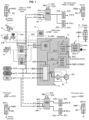
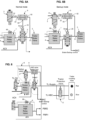
- Figure 1 shows a diagrammatical circuit layout of an electro-pneumatic braking system for a truck.
- the proposed configuration is also valid for any kind of heavy-duty vehicles including buses and coaches.
- the truck considered here can be the traction unit in a tractor/trailer configuration or it can be a utility 'carrier' truck.
- At least one front axle is a steering axle, without excluding other axle(s) having a steering function including a rear axle.
- the truck considered here can have one or more level(s) of autonomous drive functionalities, entailing reinforced needs for redundancy in braking systems.
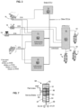
- each brake actuator (generically referred to as BA) includes a first piston 81 loaded by a first spring 82 which exerts a first effort E1 in a first direction D1 .
- Brake actuator BA also includes a second piston 83 loaded by a second spring 84 which exerts a second effort E2 in a direction D2 opposite to direction D1 .
- Piston 83 is rigid with an output rod 88 of brake actuator which drives an associated brake mechanism (brake pads, disc, etc... not shown).
- a fixed wall 86 is mounted within a housing 87 of brake actuator.
- Wall 86 defines, respectively with pistons 81 and 83, two chambers C1 , C2 of a variable volume.
- the rod 88 is coupled to the piston 83, crosses the wall 86 in an air tight manner and is coupled to the piston 81.
- Springs 82 and 84 are chosen so that effort E1 is larger than effort E2.
- effort E1 pushes piston 81 in direction D1 .
- This effort is transmitted by piston 83 to rod 88 to actuate the associated brake mechanism in a first direction.
- brake mechanism engages the brake disk(s) or drum(s) of the associated rear left wheel or wheels. This corresponds to a park brake actuation for truck. In other words, when no air under pressure is provided to brake actuator BA, the park brake of truck is actuated.
- flexible membranes or diaphragms can be used.
- the service brake actuator is the device which transforms the air pressure into a mechanical force.
- Trailer brake actuator can be similar to truck brake actuator (supplied by PBR3 for parking brake).
- the number of brake actuators can amount to 2,4,6,8, or more. It is worth noting that some brake actuators can be deprived of the parking brake function.
- the number of brake actuators can be twice the number of axles.
- each axle or group of axles is equipped with a brake module, e.g. in the illustrated example a front axle brake module FBM and one (or more) rear axle brake module RBM.
- a brake module e.g. in the illustrated example a front axle brake module FBM and one (or more) rear axle brake module RBM.
- the front axle brake module FBM provides pneumatic control pressure to the left and right front pneumatic brake actuators (FW-L, FW-R).
- the rear axle brake module RBM provides pneumatic control pressure to the left and right rear pneumatic brake actuators (RW-L,RW-R).
- Each of the front and rear axle brake modules (FBM,RBM) is an electro-pneumatic device, known per se, providing a pneumatic relay function. In short, it selectively takes air from the compressed air supply and selectively releases air to the atmosphere while following faithfully the control signals (electrical and/or pneumatic); its output is connected to the chamber C2 of the corresponding brake actuator BA .
- first air supply circuit AC1 and a second air supply circuit AC2.
- first air reservoir R1 coupled to the first air supply circuit AC1.
- first and second air supply circuits AC1,AC2 have a service pressure set around 12 bars.
- first and second air supply circuits AC1,AC2 may have a service pressure comprised in the range [5 bars - 15 bars], preferably comprised in the range [7 bars - 12 bars].
- the first air supply circuit AC1 provides air under pressure to the rear axle brake module RBM .
- the second air supply circuit AC2 provides air under pressure to the front axle brake module FBM.
- AC1 is sometimes called 'primary' circuit
- AC2 is sometimes called 'secondary' circuit, since rear brakes are usually more powerful than front brakes.
- an air compressor 60 for compressing air taken from the environment; the output of the compressor goes through a filter/dryer 62; These components are known per se thus not described in detail here.
- control units namely a 'conventional' brake control unit 73, and one or two autonomous drive ECUs 71,72.
- each of the front and rear axle brake modules FBM,RBM can be either in one integrated unit or in 3 physical units, with the PCV (pressure control valve) separated from the pneumatic relay function.
- PCV pressure control valve
- ABS function anti-locking function
- the PCV pressure control valve
- the PCV pressure control valve
- wheel speed sensors WSS At least one per braked wheel. Four are shown at the figures, but having more wheel speed sensors is possible.
- the signais from the wheel speed sensors WSS are analyzed at one or more control unit which delivers output signals to control the valves of the respective PCV (pressure control valve).
- the control unit in charge of ABS regulation can be a local control unit within the front and rear axle brake modules FBM,RBM; it can also be the conventional brake control unit 73; it can also be one or both of the autonomous drive ECUs 71,72.
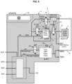
- an air production module 6 ('APM' in short), preferably housing components inside a protective enclosure, thereby providing protection against mechanical and fluid attacks.
- the air production module 6 is located behind the cabin, accessible from one side of the truck for carrier type truck, or accessible from top side if/when the cabin is tilted or rocked.
- the air production module 6 may comprise various valves, solenoids, relay valves, pressure sensor and a control unit 61.
- the air production module 6 houses the core of the parking brake function and comprises the truck PBR relay valve 8. As known per se, there is provided a parking brake electric input device 18 outputting an electric signal S18, which is delivered to the control unit 61 of the APM 6.
- PBR1, PBR2 output ports and/or lines denoted PBR1, PBR2 to distribute the park brake release pressure PBR to brake actuators.
- PBR3 output ports and/or lines denoted PBR1, PBR2 to distribute the park brake release pressure PBR to brake actuators.
- PBR3 output ports and/or lines denoted PBR1, PBR2 to distribute the park brake release pressure PBR to brake actuators.
- PBR3 output ports and/or lines denoted PBR3, PBR3, however all these lines collectively denoted PBR, are supplied by the same pressure.
- the control unit 61 of the APM 6 delivers in turn an appropriate signal to control a proportional park brake control solenoid valve 89 housed in the APM, which provides a control pressure to the parking brake relay valve 8.
- an additional braking handle 19 ('red knob') in relation with the trailer brake control.
- a corresponding electric signal S19 is delivered to the control unit 61 of the APM 6.
- a trunk portion AC0 For the air under pressure PP, coming from the compressor and filter, there is provided a trunk portion AC0 .
- the trunk portion AC0 distributes air through overflow valves (not shown) to first and second air supply circuits AC1, AC2, and optionally to a third air supply circuit AC3.
- the third air supply circuit AC3 provides a redundant air supply to the front and rear axle brake modules FBM, RBM.
- AC3 is shown in dotted line in Figure 1 .
- a first double check valve 20F is arranged at the vicinity or within the front axle brake module FBM.
- FBM is supplied by the higher pressure of AC2 or AC3.
- a first double check valve 20R is arranged at the vicinity or within the rear axle brake module RBM.
- RBM is supplied by the higher pressure of AC1 or AC3.
- figure 4 illustrates a configuration with only the primary and secondary air circuits AC1, AC2.
- the trunk portion AC0 distributes air through an overflow valve to another air supply circuit denoted AC4 for supplying the truck PBR relay valve 8 and a trailer relay valve 1.
- AC4 another air supply circuit
- AC5 another air supply circuit
- the air production module 6 may comprise various simple or double check valves, pressure limiters, purge circuits and likewise devices, etc...
- the output of the trailer relay valve 1 is coupled to a trailer brake valve 5.
- the trailer brake valve 5 is coupled to a coupling device (trailer coupling head, not shown) for supplying air to a trailer (if/when coupled).
- the trailer relay valve 1 has an input denoted 11, an output denoted 12 and a supply AC4.
- the input is supplied by a proportional trailer control solenoid valve 4 having an input 41 and an output 42.
- the trailer brake valve 5 is controlled by a line 50 coming out of the APM, more precisely from the output of the trailer relay valve 1.
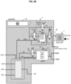
- switchover auxiliary valve 2 interposed functionally between the trailer relay valve 1 and the trailer brake valve 5.
- the switchover auxiliary valve 2 is denoted in short 'SwapV' on the drawings.
- the switchover auxiliary valve 2 is here pneumatically controlled by a control port 25 and has four input/output ports 21-24.
- the switchover auxiliary valve 2 is a 4/2 type valve.
- First port 21 is connected to the output 12 of the trailer relay valve 1.
- Second port 22 is connected to the input 51 of the trailer brake valve 5 via line 50.
- Third port 23 is connected to an outbound line called "pneumatic backup brake control line" BKC.
- Fourth port 24 is connected to the air supply circuit AC4.
- first and second ports 21,22 are in fluid communication
- fourth port 24 is closed
- third port 23 may be in communication with the atmosphere.
- first and third ports 21,23 are in fluid communication
- second and fourth ports 22,24 are in fluid communication.
- the trailer brake valve 5 is controlled by the air supply circuit AC4 (at somewhat constant pressure), and pneumatic backup brake control line BKC is supplied by the controlled pressure delivered by the trailer relay valve 1.
- the output 12 of trailer relay valve 1 can be connected selectively to the trailer brake valve 5 or to the pneumatic backup brake control line BKC, upon control port 25 status.
- the backup mode selection valve 3 is an ON/OFF electro-valve, with a pneumatic input 31 and a pneumatic output 32.
- the backup mode selection valve 3 supplies the switchover auxiliary valve 2 via a Select Low valve 9.
- the Select Low valve 9 is of a known type, performing an overall 'AND' function by selecting the lowest pressure available on its two inputs.
- the pneumatic output 93 of the Select-Low valve 9 is pressurized only if first input port 91 is pressurized AND second input port 92 is pressurized.
- the pneumatic output 32 of the backup mode selection valve 3 is connected to a first input port 91 of the select low valve 9.
- the other input port 92 of the select low valve 9 is connected to the second port 22 of the switchover auxiliary valve 2. Said otherwise, the second input port 92 of the select low valve 9 is connected to trailer supply line 50.
- the pneumatic output 93 of the select low valve 92 is connected to the control port 25 of the switchover auxiliary valve 2.
- the backup mode selection valve 3 is here a normally open valve. In normal operating mode NOM, this backup mode selection valve 3 is electrically powered therefore pneumatically closed. If there is a need to select the backup mode BKM (whatever the type of failure) electrical control is stopped on valve 3, then pneumatic state will be open thereby selecting the backup mode (input 91 is then pressurized at select-low valve 9) and if also trailer is supplied (second input port 92 pressurized).
- the switchover auxiliary valve 2 can only be caused to be activated if, beforehand, both AC4 is supplied and the trailer control solenoid valve 4 is controlled and the trailer relay valve 1 delivers pressure at its output.
- the backup mode selection valve 3 has its pneumatic output 32 connected directly to the pneumatic control port 25 of the switchover auxiliary valve 2.
- the backup mode selection valve 3 is here a normally closed valve. In this case, the control unit 61 operates with another appropriate logic.
- the brake system comprises a service brake electric input device 16 (formed generally as a brake foot pedal) delivering a first input electric signal S16.
- the brake system comprises one or more electronic brake control units (71,72,73) adapted to process the first input electric signal S16, and to deliver one or more electrical control signals (NBC,ES1,ES) to the front and rear axle brake modules FBM,RBM.
- NBC,ES1,ES electrical control signals
- a conventional brake control unit 73 in charge of handling electric signal S16 from the brake foot pedal, and in charge of delivering a braking control signal (named here NBC for normal brake control) to users such as FBM, RBM, trailer circuit.
- a braking control signal named here NBC for normal brake control
- autonomous drive control units 71,72 may be provided as redundant units which work either in a parallel mode or in a master/slave mode.
- electrical control signals delivered by first autonomous drive control unit 71 are denoted ES1
- electrical control signals delivered by second autonomous drive control unit 72 are denoted ES2.
- First and second autonomous drive control units 71,72 rely at least on cameras 75 which provides a flow of images S75 which are analyzed in autonomous drive control units 71,72.
- cameras 75 which provides a flow of images S75 which are analyzed in autonomous drive control units 71,72.
- There may be provided other type of sensors like radars, lidars, or the like inertial sensors, and also communication data received from various traffic aware entities (from fixed or mobile entities).
- Each of the front and rear axle brake modules (FBM,RBM) is controlled by the above mentioned electrical control signals (NBC and/or ES1 and/or ES2) under a normal mode called "normal brake operating mode" NOM.
- backup brake operating mode BKM Whenever this normal mode is not fully operative, in particular from an electrical problem, disruption/lack of electrical supply at the electronic brake control units (71,72,73), from the perspective of at least one of to the front and rear axle brake modules FBM,RBM, there is provided in the system an alternative mode called backup brake operating mode BKM.
- each of the front and rear axle brake modules can be controlled by a pneumatic backup brake control line BKC under the backup brake operating mode BKM.
- the brake foot pedal 16 is not configured to deliver pneumatic signals, the inventors have found a way to use the existing trailer relay valve 1 to fulfil the generation of an appropriate pneumatic backup brake control line.
- the control unit 61 controls the backup mode selection valve 3 to open or close (respectively Fig 2A , 2B ), the output of backup mode selection valve 3, if relevant via the low select valve 9, controls pneumatically the switchover auxiliary valve 2, the latter changes to the actuated state ( Fig 5B ), and the output 12 of trailer relay valve is connected to the pneumatic backup brake control line BKC.
- the output 12 of trailer relay valve 1 is connected to the trailer brake valve 5 (trailer brake 'interface' as generic term), and under the backup brake operating mode BKM the output 12 of trailer relay valve is connected to the pneumatic backup brake control line BKC.
- pneumatic backup brake control line BKC is output and controlled by the air production module 6, independently of the brake control unit 73 and/or autonomous drive control units 71,72.
- the control unit 61 of the APM 6 may take the decision to go to backup brake operating mode BKM whenever it does not receive expected proper electrical signals from the other electronic control units. For example the control unit 61 of the APM 6 may expect to receive "I'm alive & healthy" signal from the brake control unit 73 and/or from one or more of the autonomous drive control units 71,72, and in the case those signals are not properly received, control unit 61 of the APM 6 may control the backup mode selection valve 3 so that the switchover auxiliary valve 2 is switched to backup brake operating mode BKM.
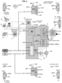
- Figure 8 shows a variant embodiment.
- the second input 92 of the select-low valve 9 is here connected to a park brake release line 99 (inste ad of trailer brake interface supply line 50 in Fig 2A ).
- NOM park brake release line
- the backup mode selection valve 3 is electrically powered therefore pneumatically closed. If there is a need to select the backup mode (whatever the type of failure) the backup selection valve 3 is no longer controlled electrically and becomes pneumatically open.
- backup selection valve 3 When backup selection valve 3 is pneumatically open, input 91 pressurized at select-low valve 9, and the output 93 is pressurized with an extra condition: the park brake shall be released (second input 92 pressurized).
- backup mode BKM is already selected, an electrical failure regarding the supply/control of the backup selection valve 3 does not change the current mode, and backup mode BKM is maintained.
- the park brake state is a stable position : either applied or released. Therefore, only when the brake is released, i.e. in driving conditions, the backup mode can be selected.
- Swap valve 2 When the truck is parked, Swap valve 2 will remain at rest position (normal control of trailer interface) whatever the state of backup mode selection valve 3.
- a back end loop circuit is provided with a restriction 68. This ensures stability of the pneumatic control and discards some inadvertent transients.
- a tractor protection valve 5' As shown in figure 6 , in the braking system according to US standard, unlike the trailer brake valve already described above, there is provided as trailer brake interface a tractor protection valve 5'.
- the second port 22 of the switchover auxiliary valve 2 is connected directly to the trailer coupling head -red hand-, and is also connected to the control port of the tractor protection valve 5'. Thanks to this valve, the normal braking line TL-NBC is connected to the trailer coupling head -blue hand- when pressure is supplied in the TL-Supply Line.
- References 181,182,184 denote the internal pneumatic lines within the air production which respectively supply the parking brake relay valve 8, the proportional park brake control solenoid valve 89, the trailer relay valve 1, the proportional trailer control solenoid valve 4, the backup mode selection valve 3.
- the proportional park brake control solenoid valve 89 is controlled by control unit 61 through line 69; the proportional trailer control solenoid valve 4 is controlled by control unit 61 through line 64; the backup mode selection valve 3 is controlled by control unit 61 through line 63.
- the pneumatic brake system described above constitutes the main service brake system of the vehicle which is used to slow down and to stop the vehicle during normal operation, whatever the speed of the vehicle.
- the park brake system is used mainly to maintain the vehicle stopped when it is not in use.
- the park brake system can be least partly combined with the service brake system; nevertheless, a park brake system can be independent of the service brake system, it can for example comprise a system for blocking the vehicle transmission.
- Heavy-duty vehicles such as trucks and buses, are also often equipped with a deceleration system, which is only capable of slowing down a vehicle, but often not capable of effectively stopping the vehicle completely within a reasonable distance.
- deceleration systems such as hydro-dynamic brakes or electro-dynamic brakes, are mostly efficient when the vehicle is riding above a certain speed.
- Such deceleration systems are by essence different from the pneumatic brake system described above.
Landscapes
- Engineering & Computer Science (AREA)
- Mechanical Engineering (AREA)
- Transportation (AREA)
- General Engineering & Computer Science (AREA)
- Regulating Braking Force (AREA)
- Valves And Accessory Devices For Braking Systems (AREA)
- Braking Systems And Boosters (AREA)
Claims (14)
- Elektronisch gesteuertes pneumatisches Bremssystem für ein Kraftfahrzeug, wobei das System konfiguriert ist, um entweder in einem normalen Bremsbetriebsmodus (NOM) oder in einem Backup-Bremsbetriebsmodus (BKM) betrieben zu werden, das System umfassend:- ein oder mehrere Vorderachsenbremsmodule (FBM) zum Bereitstellen von pneumatischem Steuerdruck für den linken und den rechten vorderen pneumatischen Bremsaktuator (FW-L, FW-R),- ein oder mehrere Hinterachsenbremsmodule (RBM) zum Bereitstellen von pneumatischem Steuerdruck für den linken und den rechten hinteren pneumatischen Bremsaktuator (RW-L, RW-R),- eine Anhängerbremsschnittstelle (5) und eine Kupplungsvorrichtung zur Versorgung eines Anhängers mit Luft,- ein Lufterzeugungsmodul (6) zum selektiven Bereitstellen von Luft unter Druck zu den elektronischen Achsenbremsmodulen (FBM, RBM) über mindestens einen ersten Luftversorgungskreis (AC1) und einen zweiten Luftversorgungskreis (AC2) und zu einem Anhängerkreis,- mindestens zwei Luftreservoirs (R1, R2), die jeweils mit dem ersten und dem zweiten Luftversorgungskreis verbunden sind,- ein Anhänger-Relaisventil (1), das einen Ausgang (12) aufweist,wobei jedes von dem Vorder- und dem Hinterachsenbremsmodul (FBM, RBM) in dem normalen Bremsbetriebsmodus (NOM) durch ein elektrisches Steuersignal (NBC, ES1, ES2) gesteuert wird und in dem Backup-Bremsbetriebsmodus (BKM) durch eine pneumatische Backup-Bremssteuerleitung (BKC) gesteuert wird,dadurch gekennzeichnet, dass der Ausgang (12) des Anhänger-Relaisventils (1) in dem normalen Bremsbetriebsmodus (NOM) mit der Anhängerbremsschnittstelle (5) verbunden ist und der Ausgang (12) des Anhänger-Relaisventils in dem Backup-Bremsbetriebsmodus (BKM) mit der pneumatischen Backup-Bremssteuerleitung (BKC) verbunden ist, wobei das Bremssystem ferner Folgendes umfasst:- ein Umschalt-Hilfsventil (2) zum selektiven Verbinden des Ausgangs (12) des Anhänger-Relaisventils (1) entweder mit der Anhängerbremsschnittstelle (5) oder mit der pneumatischen Backup-Bremssteuerleitung (BKC), abhängig von dem aktuellen Betriebsmodus (NOM, BKM), und gesteuert durch mindestens:- ein Backup-Modus-Auswahlventil (3).
- Bremssystem nach Anspruch 1, wobei das Umschalt-Hilfsventil (2) ein 4/2-Ventil mit vier Anschlüssen und zwei Kolbenpositionen ist, mit einer pneumatischen Steuerung.
- Bremssystem nach einem der Ansprüche 1 bis 2, wobei das Backup-Modus-Auswahlventil (3) ein EIN/AUS-Elektroventil ist, dessen Ausgang (32) mit dem pneumatischen Steueranschluss (25) des Umschalt-Hilfsventils (2) verbunden ist.
- Bremssystem nach einem der Ansprüche 1 bis 2, ferner umfassend ein Select-Low-Ventil (9), dessen Ausgang (93) mit dem pneumatischen Steueranschluss (25) des Umschalt-Hilfsventils verbunden ist.
- Bremssystem nach Anspruch 4, wobei ein Eingangsanschluss (92) des Select-Low-Ventils (9) von einer Parkbremselöseleitung (99) versorgt wird und der andere Eingangsanschluss (91) des Select-Low-Ventils (9) von dem Backup-Modus-Auswahlventil (3) versorgt wird.
- Bremssystem nach Anspruch 4, wobei ein Eingangsanschluss (92) des Select-Low-Ventils (9) von einer Versorgungsleitung (50) zu der Anhängerbremsschnittstelle (5) versorgt wird, und der andere Eingangsanschluss (91) des Select-Low-Ventils (9) von dem Backup-Modus-Auswahlventil (3) versorgt wird.
- Bremssystem nach einem der Ansprüche 1 bis 6, wobei das Backup-Modus-Auswahlventil (3) ein normalerweise offenes Ventil ist, wobei das Backup-Modus-Auswahlventil (3) durch eine Lufterzeugungsmodul-Steuereinheit (61) gesteuert wird, die in dem Lufterzeugungsmodul (6) untergebracht ist.
- Bremssystem nach einem der Ansprüche 1 bis 7, ferner umfassend ein proportionales Anhängersteuermagnetventil (4), um einen Steuerdruck für das Anhänger-Relaisventil (1) bereitzustellen.
- Bremssystem nach einem der Ansprüche 1 bis 8, ferner umfassend:- eine elektrische Betriebsbremsen-Eingangsvorrichtung (16), die ein erstes elektrisches Eingangssignal (S 16) liefert;- mindestens eine elektronische Bremssteuereinheit (71,72,73), die angepasst ist, um das erste elektrische Eingangssignal zu verarbeiten und elektrische Steuersignale (NBC, ES1, ES2) an das Vorder- und das Hinterachsenbremsmodul (FBM, RBM) zu liefern.
- Bremssystem nach Anspruch 9, wobei die pneumatische Backup-Bremssteuerleitung (BKC) unabhängig von der Bremssteuereinheit (73) und/oder autonomen Antriebssteuereinheiten (71,72) durch das Lufterzeugungsmodul (6) ausgegeben und gesteuert wird.
- Bremssystem nach einem der Ansprüche 1 bis 9, ferner umfassend:
ein LKW-Parkbremsen-Relaisventil (8),- eine elektrische Parkbremsen-Eingangsvorrichtung (18), die ein zweites elektrisches Eingangssignal (S18) liefert,- eine Lufterzeugungsmodul-Steuereinheit (61), die angepasst ist, um das zweite elektrische Eingangssignal (S18) zu verarbeiten und Steuersignale an ein proportionales Parkbremssteuermagnetventil (89) zu liefern, das einen Steuerdruck für das Parkbremsen-Relaisventil (8) bereitstellt. - Bremssystem nach einem der Ansprüche 1 bis 11, wobei das Umschalt-Hilfsventil (2), das Backup-Modus-Auswahlventil (3) und optional das Select-Low-Ventil (9) innerhalb des Lufterzeugungsmoduls (6) untergebracht sind.
- Bremssystem nach einem der Ansprüche 1 bis 12, wobei ein dritter Luftversorgungskreis (AC3) zum Bereitstellen einer redundanten pneumatischen Versorgung des Vorder- und des Hinterachsenbremsmoduls (FBM, RBM) bereitgestellt ist.
- Fahrzeug, umfassend ein System nach einem der Ansprüche 1 bis 13.
Applications Claiming Priority (1)
| Application Number | Priority Date | Filing Date | Title |
|---|---|---|---|
| PCT/EP2018/061283 WO2019210952A1 (en) | 2018-05-03 | 2018-05-03 | Heavy duty vehicle redundant braking system |
Publications (3)
| Publication Number | Publication Date |
|---|---|
| EP3564082A1 EP3564082A1 (de) | 2019-11-06 |
| EP3564082B1 EP3564082B1 (de) | 2021-01-27 |
| EP3564082B2 true EP3564082B2 (de) | 2025-06-18 |
Family
ID=62165540
Family Applications (1)
| Application Number | Title | Priority Date | Filing Date |
|---|---|---|---|
| EP19172178.6A Active EP3564082B2 (de) | 2018-05-03 | 2019-05-02 | Redundantes bremssystem für schwerlastfahrzeuge |
Country Status (4)
| Country | Link |
|---|---|
| US (2) | US20210114572A1 (de) |
| EP (1) | EP3564082B2 (de) |
| CN (1) | CN112074439B (de) |
| WO (1) | WO2019210952A1 (de) |
Families Citing this family (21)
| Publication number | Priority date | Publication date | Assignee | Title |
|---|---|---|---|---|
| DE102016012617A1 (de) * | 2016-10-20 | 2018-04-26 | Lucas Automotive Gmbh | System mit getrennten Steuereinheiten für die Stelleinheiten einer elektrischen Parkbremse |
| CN112055675B (zh) * | 2018-05-03 | 2022-11-01 | 沃尔沃卡车集团 | 重型车辆冗余制动系统 |
| WO2019210952A1 (en) * | 2018-05-03 | 2019-11-07 | Volvo Truck Corporation | Heavy duty vehicle redundant braking system |
| DE102018126094A1 (de) * | 2018-10-19 | 2020-04-23 | Wabco Gmbh | Aktuatormodul für ein Bremssystem eines Fahrzeugs |
| DE102019106591A1 (de) * | 2019-03-15 | 2020-09-17 | Wabco Gmbh | Elektronisch steuerbares Bremssystem mit zwei Rückfallebenen |
| DE102019133011A1 (de) * | 2019-12-04 | 2021-06-10 | Zf Cv Systems Global Gmbh | Monostabil und fehlertolerant ausgelegte Feststellbremsventilanordnung |
| JP7411805B2 (ja) * | 2019-12-10 | 2024-01-11 | ボルボトラックコーポレーション | 冗長ブレーキ装置システムの制御 |
| US11427175B2 (en) | 2019-12-16 | 2022-08-30 | Waymo Llc | Vehicle braking systems and methods |
| WO2021164856A1 (en) * | 2020-02-18 | 2021-08-26 | Volvo Truck Corporation | Double trailer connections and automatic detection |
| US11407394B2 (en) * | 2020-03-09 | 2022-08-09 | Bendix Commercial Vehicle Systems Llc | Method and parking brake apparatus for an autonomously drivable vehicle |
| GB2598967B (en) * | 2020-09-22 | 2022-10-05 | Caterpillar Sarl | Brake system |
| EP4001031B1 (de) | 2020-11-13 | 2024-01-03 | Volvo Truck Corporation | Elektropneumatisches bremssystem für ein fahrzeug mit einem feststellbremssystem als reserveverzögerungssystem |
| US11772624B2 (en) * | 2021-01-08 | 2023-10-03 | Volvo Truck Corporation | Braking arrangement for a vehicle |
| EP4043305B1 (de) * | 2021-02-10 | 2023-10-11 | Volvo Truck Corporation | Pneumatisches bremssystem für eine achse eines fahrzeugs |
| US11938915B2 (en) * | 2021-03-17 | 2024-03-26 | Volvo Truck Corporat on | Braking arrangement for a vehicle |
| EP4116161B1 (de) * | 2021-07-06 | 2024-03-06 | Volvo Truck Corporation | Redundantes bremssystem für schwerlastfahrzeuge |
| EP4163167B1 (de) * | 2021-10-07 | 2024-04-03 | Volvo Truck Corporation | Nutzfahrzeug mit einem pneumatischen system und verfahren zur steuerung eines pneumatischen systems |
| EP4594146A1 (de) * | 2022-10-01 | 2025-08-06 | ZF CV Systems Global GmbH | Feststellbremsventil für einen anhänger und bremsanlage sowie verfahren zur steuerung einer feststellbremse |
| CN115447551A (zh) * | 2022-10-25 | 2022-12-09 | 安徽苇渡控股有限公司 | 制动系统及车辆 |
| EP4400373A1 (de) * | 2023-01-11 | 2024-07-17 | ZF CV Systems Global GmbH | Elektropneumatische ventileinheit für ein nutzfahrzeug |
| US12409824B1 (en) * | 2024-12-20 | 2025-09-09 | Gatik Ai Inc. | Drive-by-wire vehicle architecture |
Citations (5)
| Publication number | Priority date | Publication date | Assignee | Title |
|---|---|---|---|---|
| WO2003004333A1 (de) † | 2001-07-05 | 2003-01-16 | Knorr-Bremse Systeme für Nutzfahrzeuge GmbH | Druckmittelbetätigte bremsanlage einer zugfahrzeug-anhänger-kombination |
| EP1561661A1 (de) † | 2004-01-30 | 2005-08-10 | ArvinMeritor Technology, LLC | Elektronisches Fahrzeugbremssystem mit Hilfsbremsfunktion |
| DE102005062907B3 (de) † | 2005-12-29 | 2007-05-10 | Knorr-Bremse Systeme für Nutzfahrzeuge GmbH | Druckmittelbetätigtes Bremssystem mit redundanter Steuerung der Bremsaktuatoren |
| DE102008009043B3 (de) † | 2008-02-14 | 2009-05-14 | Knorr-Bremse Systeme für Nutzfahrzeuge GmbH | Elektronisch geregeltes Bremssystem mit redundanter Steuerung der Bremsaktuatoren |
| WO2018172256A1 (de) † | 2017-03-21 | 2018-09-27 | Wabco Gmbh | Elektronisch steuerbares bremssystem sowie verfahren zum steuern des elektronisch steuerbaren bremssystems |
Family Cites Families (17)
| Publication number | Priority date | Publication date | Assignee | Title |
|---|---|---|---|---|
| DE19923455C2 (de) * | 1999-05-21 | 2001-03-15 | Knorr Bremse Systeme | Druckmittelbetätigte Fahrzeugbremsanlage |
| DE19935979C2 (de) | 1999-07-30 | 2001-07-19 | Knorr Bremse Systeme | Druckmittelbetätigte Fahrzeugbremsanlage |
| EP1132274B1 (de) | 2000-02-26 | 2004-04-07 | WABCO GmbH & CO. OHG | Bremsdruckmodulator für elektronische Bremsanlage |
| JP2006044624A (ja) * | 2004-08-06 | 2006-02-16 | Wabco Gmbh & Co Ohg | 車両用の圧力媒体で作動せしめられる制動システム |
| DE102008003381B4 (de) | 2008-01-07 | 2024-10-02 | Zf Cv Systems Hannover Gmbh | Bremsanlage für ein Fahrzeug |
| DE102010021909A1 (de) | 2010-05-28 | 2011-12-01 | Knorr-Bremse Systeme für Nutzfahrzeuge GmbH | Verfahren zur Steuerung einer Bremsanlage eines Fahrzeugs mit elektronisch geregeltem Hinterachsbremskreis und pneumatisch gesteuertem Vorderachsbremskreis |
| WO2013093545A1 (en) | 2011-12-23 | 2013-06-27 | Renault Trucks | Electronically controlled pneumatic brake system for an automotive vehicle and automotive vehicle equipped with such a system |
| WO2014063720A1 (en) * | 2012-10-25 | 2014-05-01 | Renault Trucks | Electronically controlled pneumatic brake system for an automotive vehicle, automotive vehicle equipped with such a system and method for controlling such a system |
| DE102014006615A1 (de) | 2014-05-08 | 2015-11-12 | Wabco Gmbh | Druckmittelbetriebenes Bremssystem für ein Kraftfahrzeug sowie Kraftfahrzeug damit |
| DE102014011422A1 (de) | 2014-07-31 | 2016-02-04 | Wabco Gmbh | Bremsdruckmodulator eines elektronischen Bremssystems eines Nutzfahrzeugs |
| DE102017002721A1 (de) * | 2017-03-21 | 2018-09-27 | Wabco Gmbh | Elektronisch steuerbares Bremssystem sowie Verfahren zum Steuern des elektronisch steuerbaren Bremssystems mit rein elektrischem Bremswertgeber |
| DE102017002719A1 (de) * | 2017-03-21 | 2018-09-27 | Wabco Gmbh | Elektronisch steuerbares Bremssystem sowie Verfahren zum Steuern des elektronisch steuerbaren Bremssystems |
| DE102017002718A1 (de) * | 2017-03-21 | 2018-09-27 | Wabco Gmbh | Elektronisch steuerbares Bremssystem sowie Verfahren zum Steuern des elektronisch steuerbaren Bremssystems |
| DE102018102764A1 (de) * | 2018-02-07 | 2019-08-08 | Haldex Brake Products Aktiebolag | Bremsanlage für ein Nutzfahrzeug, Druckluftaufbereitungseinheit und Verwendung einer Druckluftaufbereitungseinheit |
| JP7189967B2 (ja) * | 2018-05-03 | 2022-12-14 | ボルボトラックコーポレーション | 冗長ブレーキ装置を有する車両の冗長モーション制御 |
| WO2019210952A1 (en) * | 2018-05-03 | 2019-11-07 | Volvo Truck Corporation | Heavy duty vehicle redundant braking system |
| CN112055675B (zh) * | 2018-05-03 | 2022-11-01 | 沃尔沃卡车集团 | 重型车辆冗余制动系统 |
-
2018
- 2018-05-03 WO PCT/EP2018/061283 patent/WO2019210952A1/en not_active Ceased
- 2018-05-03 US US17/051,955 patent/US20210114572A1/en not_active Abandoned
- 2018-05-03 CN CN201880093096.7A patent/CN112074439B/zh active Active
-
2019
- 2019-04-30 US US16/398,346 patent/US11180127B2/en active Active
- 2019-05-02 EP EP19172178.6A patent/EP3564082B2/de active Active
Patent Citations (5)
| Publication number | Priority date | Publication date | Assignee | Title |
|---|---|---|---|---|
| WO2003004333A1 (de) † | 2001-07-05 | 2003-01-16 | Knorr-Bremse Systeme für Nutzfahrzeuge GmbH | Druckmittelbetätigte bremsanlage einer zugfahrzeug-anhänger-kombination |
| EP1561661A1 (de) † | 2004-01-30 | 2005-08-10 | ArvinMeritor Technology, LLC | Elektronisches Fahrzeugbremssystem mit Hilfsbremsfunktion |
| DE102005062907B3 (de) † | 2005-12-29 | 2007-05-10 | Knorr-Bremse Systeme für Nutzfahrzeuge GmbH | Druckmittelbetätigtes Bremssystem mit redundanter Steuerung der Bremsaktuatoren |
| DE102008009043B3 (de) † | 2008-02-14 | 2009-05-14 | Knorr-Bremse Systeme für Nutzfahrzeuge GmbH | Elektronisch geregeltes Bremssystem mit redundanter Steuerung der Bremsaktuatoren |
| WO2018172256A1 (de) † | 2017-03-21 | 2018-09-27 | Wabco Gmbh | Elektronisch steuerbares bremssystem sowie verfahren zum steuern des elektronisch steuerbaren bremssystems |
Also Published As
| Publication number | Publication date |
|---|---|
| US11180127B2 (en) | 2021-11-23 |
| US20190337502A1 (en) | 2019-11-07 |
| EP3564082B1 (de) | 2021-01-27 |
| US20210114572A1 (en) | 2021-04-22 |
| EP3564082A1 (de) | 2019-11-06 |
| WO2019210952A1 (en) | 2019-11-07 |
| CN112074439B (zh) | 2023-02-17 |
| CN112074439A (zh) | 2020-12-11 |
Similar Documents
| Publication | Publication Date | Title |
|---|---|---|
| EP3564082B2 (de) | Redundantes bremssystem für schwerlastfahrzeuge | |
| CN108883755B (zh) | 商用车辆中的能电子控制的气动制动系统和用于电子控制气动制动系统的方法 | |
| CN112055675B (zh) | 重型车辆冗余制动系统 | |
| EP3787943B1 (de) | Redundante bremseinheit für ein bremssystem und system damit | |
| US10654458B2 (en) | Electronic brake system for a compressed air braking system of a utility vehicle | |
| CN114761294B (zh) | 单稳态和容错设计的驻车制动阀组件 | |
| KR102310690B1 (ko) | 차량 브레이크 시스템 | |
| CN106458192A (zh) | 用于机动车的制动系统 | |
| US20190217833A1 (en) | Air Treatment Unit for a Brake System of a Utility Vehicle, and Method for Operating an Air Treatment Unit | |
| KR102207124B1 (ko) | 상용차의 브레이크 장치를 위한 공기 처리 유닛, 브레이크 장치 및 공기 처리 유닛을 작동하기 위한 방법 | |
| CN106660536B (zh) | 车辆的具有集成的紧急气源压力容器的压缩空气装置 | |
| CN107531222B (zh) | 用于调节挂车中的制动器的方法 | |
| US20220297656A1 (en) | Fail-safety valve unit for a parking brake function and parking brake valve arrangement | |
| US20240198996A1 (en) | Electronically controllable pneumatic braking system with failsafe braking application for autonomous driving, having only one shuttle valve | |
| CN112512881B (zh) | 具有部分解耦的tcv(欧洲驱控)的电动气动手刹(eph) | |
| CN118265642A (zh) | 具有经由主调制器的放气路径进行压力馈入的故障安全的冗余制动系统 | |
| US6644758B1 (en) | Automotive braking system actuated by a pressure fluid | |
| EP1789296A1 (de) | Anhängerbremssystem | |
| CN115583227A (zh) | 重型车辆冗余制动系统 | |
| US8226173B1 (en) | Supplemental brake system | |
| CN119585163A (zh) | 挂车的具有气动的驱控部的机电式的制动系统 | |
| JPH0958442A (ja) | トラクタ・トレーラ連結車におけるトラクタ側エアブレーキシステム |
Legal Events
| Date | Code | Title | Description |
|---|---|---|---|
| PUAI | Public reference made under article 153(3) epc to a published international application that has entered the european phase |
Free format text: ORIGINAL CODE: 0009012 |
|
| STAA | Information on the status of an ep patent application or granted ep patent |
Free format text: STATUS: THE APPLICATION HAS BEEN PUBLISHED |
|
| AK | Designated contracting states |
Kind code of ref document: A1 Designated state(s): AL AT BE BG CH CY CZ DE DK EE ES FI FR GB GR HR HU IE IS IT LI LT LU LV MC MK MT NL NO PL PT RO RS SE SI SK SM TR |
|
| AX | Request for extension of the european patent |
Extension state: BA ME |
|
| STAA | Information on the status of an ep patent application or granted ep patent |
Free format text: STATUS: REQUEST FOR EXAMINATION WAS MADE |
|
| 17P | Request for examination filed |
Effective date: 20200428 |
|
| RBV | Designated contracting states (corrected) |
Designated state(s): AL AT BE BG CH CY CZ DE DK EE ES FI FR GB GR HR HU IE IS IT LI LT LU LV MC MK MT NL NO PL PT RO RS SE SI SK SM TR |
|
| RIC1 | Information provided on ipc code assigned before grant |
Ipc: B60T 13/68 20060101AFI20200615BHEP |
|
| GRAP | Despatch of communication of intention to grant a patent |
Free format text: ORIGINAL CODE: EPIDOSNIGR1 |
|
| STAA | Information on the status of an ep patent application or granted ep patent |
Free format text: STATUS: GRANT OF PATENT IS INTENDED |
|
| INTG | Intention to grant announced |
Effective date: 20200910 |
|
| GRAS | Grant fee paid |
Free format text: ORIGINAL CODE: EPIDOSNIGR3 |
|
| GRAA | (expected) grant |
Free format text: ORIGINAL CODE: 0009210 |
|
| STAA | Information on the status of an ep patent application or granted ep patent |
Free format text: STATUS: THE PATENT HAS BEEN GRANTED |
|
| AK | Designated contracting states |
Kind code of ref document: B1 Designated state(s): AL AT BE BG CH CY CZ DE DK EE ES FI FR GB GR HR HU IE IS IT LI LT LU LV MC MK MT NL NO PL PT RO RS SE SI SK SM TR |
|
| REG | Reference to a national code |
Ref country code: GB Ref legal event code: FG4D |
|
| REG | Reference to a national code |
Ref country code: CH Ref legal event code: EP |
|
| REG | Reference to a national code |
Ref country code: AT Ref legal event code: REF Ref document number: 1358076 Country of ref document: AT Kind code of ref document: T Effective date: 20210215 |
|
| REG | Reference to a national code |
Ref country code: IE Ref legal event code: FG4D |
|
| REG | Reference to a national code |
Ref country code: DE Ref legal event code: R096 Ref document number: 602019002325 Country of ref document: DE |
|
| REG | Reference to a national code |
Ref country code: NL Ref legal event code: FP |
|
| REG | Reference to a national code |
Ref country code: SE Ref legal event code: TRGR |
|
| REG | Reference to a national code |
Ref country code: LT Ref legal event code: MG9D |
|
| REG | Reference to a national code |
Ref country code: AT Ref legal event code: MK05 Ref document number: 1358076 Country of ref document: AT Kind code of ref document: T Effective date: 20210127 |
|
| PG25 | Lapsed in a contracting state [announced via postgrant information from national office to epo] |
Ref country code: PT Free format text: LAPSE BECAUSE OF FAILURE TO SUBMIT A TRANSLATION OF THE DESCRIPTION OR TO PAY THE FEE WITHIN THE PRESCRIBED TIME-LIMIT Effective date: 20210527 Ref country code: NO Free format text: LAPSE BECAUSE OF FAILURE TO SUBMIT A TRANSLATION OF THE DESCRIPTION OR TO PAY THE FEE WITHIN THE PRESCRIBED TIME-LIMIT Effective date: 20210427 Ref country code: LT Free format text: LAPSE BECAUSE OF FAILURE TO SUBMIT A TRANSLATION OF THE DESCRIPTION OR TO PAY THE FEE WITHIN THE PRESCRIBED TIME-LIMIT Effective date: 20210127 Ref country code: BG Free format text: LAPSE BECAUSE OF FAILURE TO SUBMIT A TRANSLATION OF THE DESCRIPTION OR TO PAY THE FEE WITHIN THE PRESCRIBED TIME-LIMIT Effective date: 20210427 Ref country code: HR Free format text: LAPSE BECAUSE OF FAILURE TO SUBMIT A TRANSLATION OF THE DESCRIPTION OR TO PAY THE FEE WITHIN THE PRESCRIBED TIME-LIMIT Effective date: 20210127 Ref country code: FI Free format text: LAPSE BECAUSE OF FAILURE TO SUBMIT A TRANSLATION OF THE DESCRIPTION OR TO PAY THE FEE WITHIN THE PRESCRIBED TIME-LIMIT Effective date: 20210127 Ref country code: GR Free format text: LAPSE BECAUSE OF FAILURE TO SUBMIT A TRANSLATION OF THE DESCRIPTION OR TO PAY THE FEE WITHIN THE PRESCRIBED TIME-LIMIT Effective date: 20210428 |
|
| PG25 | Lapsed in a contracting state [announced via postgrant information from national office to epo] |
Ref country code: AT Free format text: LAPSE BECAUSE OF FAILURE TO SUBMIT A TRANSLATION OF THE DESCRIPTION OR TO PAY THE FEE WITHIN THE PRESCRIBED TIME-LIMIT Effective date: 20210127 Ref country code: RS Free format text: LAPSE BECAUSE OF FAILURE TO SUBMIT A TRANSLATION OF THE DESCRIPTION OR TO PAY THE FEE WITHIN THE PRESCRIBED TIME-LIMIT Effective date: 20210127 Ref country code: PL Free format text: LAPSE BECAUSE OF FAILURE TO SUBMIT A TRANSLATION OF THE DESCRIPTION OR TO PAY THE FEE WITHIN THE PRESCRIBED TIME-LIMIT Effective date: 20210127 Ref country code: LV Free format text: LAPSE BECAUSE OF FAILURE TO SUBMIT A TRANSLATION OF THE DESCRIPTION OR TO PAY THE FEE WITHIN THE PRESCRIBED TIME-LIMIT Effective date: 20210127 |
|
| PG25 | Lapsed in a contracting state [announced via postgrant information from national office to epo] |
Ref country code: IS Free format text: LAPSE BECAUSE OF FAILURE TO SUBMIT A TRANSLATION OF THE DESCRIPTION OR TO PAY THE FEE WITHIN THE PRESCRIBED TIME-LIMIT Effective date: 20210527 |
|
| REG | Reference to a national code |
Ref country code: DE Ref legal event code: R026 Ref document number: 602019002325 Country of ref document: DE |
|
| PG25 | Lapsed in a contracting state [announced via postgrant information from national office to epo] |
Ref country code: EE Free format text: LAPSE BECAUSE OF FAILURE TO SUBMIT A TRANSLATION OF THE DESCRIPTION OR TO PAY THE FEE WITHIN THE PRESCRIBED TIME-LIMIT Effective date: 20210127 Ref country code: CZ Free format text: LAPSE BECAUSE OF FAILURE TO SUBMIT A TRANSLATION OF THE DESCRIPTION OR TO PAY THE FEE WITHIN THE PRESCRIBED TIME-LIMIT Effective date: 20210127 Ref country code: SM Free format text: LAPSE BECAUSE OF FAILURE TO SUBMIT A TRANSLATION OF THE DESCRIPTION OR TO PAY THE FEE WITHIN THE PRESCRIBED TIME-LIMIT Effective date: 20210127 |
|
| PLBI | Opposition filed |
Free format text: ORIGINAL CODE: 0009260 |
|
| PG25 | Lapsed in a contracting state [announced via postgrant information from national office to epo] |
Ref country code: RO Free format text: LAPSE BECAUSE OF FAILURE TO SUBMIT A TRANSLATION OF THE DESCRIPTION OR TO PAY THE FEE WITHIN THE PRESCRIBED TIME-LIMIT Effective date: 20210127 Ref country code: SK Free format text: LAPSE BECAUSE OF FAILURE TO SUBMIT A TRANSLATION OF THE DESCRIPTION OR TO PAY THE FEE WITHIN THE PRESCRIBED TIME-LIMIT Effective date: 20210127 Ref country code: DK Free format text: LAPSE BECAUSE OF FAILURE TO SUBMIT A TRANSLATION OF THE DESCRIPTION OR TO PAY THE FEE WITHIN THE PRESCRIBED TIME-LIMIT Effective date: 20210127 |
|
| 26 | Opposition filed |
Opponent name: ZF CV SYSTEMS EUROPE BV Effective date: 20211027 |
|
| PLAX | Notice of opposition and request to file observation + time limit sent |
Free format text: ORIGINAL CODE: EPIDOSNOBS2 |
|
| PG25 | Lapsed in a contracting state [announced via postgrant information from national office to epo] |
Ref country code: ES Free format text: LAPSE BECAUSE OF FAILURE TO SUBMIT A TRANSLATION OF THE DESCRIPTION OR TO PAY THE FEE WITHIN THE PRESCRIBED TIME-LIMIT Effective date: 20210127 Ref country code: LU Free format text: LAPSE BECAUSE OF NON-PAYMENT OF DUE FEES Effective date: 20210502 Ref country code: AL Free format text: LAPSE BECAUSE OF FAILURE TO SUBMIT A TRANSLATION OF THE DESCRIPTION OR TO PAY THE FEE WITHIN THE PRESCRIBED TIME-LIMIT Effective date: 20210127 Ref country code: MC Free format text: LAPSE BECAUSE OF FAILURE TO SUBMIT A TRANSLATION OF THE DESCRIPTION OR TO PAY THE FEE WITHIN THE PRESCRIBED TIME-LIMIT Effective date: 20210127 |
|
| REG | Reference to a national code |
Ref country code: BE Ref legal event code: MM Effective date: 20210531 |
|
| PG25 | Lapsed in a contracting state [announced via postgrant information from national office to epo] |
Ref country code: SI Free format text: LAPSE BECAUSE OF FAILURE TO SUBMIT A TRANSLATION OF THE DESCRIPTION OR TO PAY THE FEE WITHIN THE PRESCRIBED TIME-LIMIT Effective date: 20210127 |
|
| PLBB | Reply of patent proprietor to notice(s) of opposition received |
Free format text: ORIGINAL CODE: EPIDOSNOBS3 |
|
| PG25 | Lapsed in a contracting state [announced via postgrant information from national office to epo] |
Ref country code: IT Free format text: LAPSE BECAUSE OF FAILURE TO SUBMIT A TRANSLATION OF THE DESCRIPTION OR TO PAY THE FEE WITHIN THE PRESCRIBED TIME-LIMIT Effective date: 20210127 Ref country code: IE Free format text: LAPSE BECAUSE OF NON-PAYMENT OF DUE FEES Effective date: 20210502 |
|
| PG25 | Lapsed in a contracting state [announced via postgrant information from national office to epo] |
Ref country code: IS Free format text: LAPSE BECAUSE OF FAILURE TO SUBMIT A TRANSLATION OF THE DESCRIPTION OR TO PAY THE FEE WITHIN THE PRESCRIBED TIME-LIMIT Effective date: 20210527 |
|
| PG25 | Lapsed in a contracting state [announced via postgrant information from national office to epo] |
Ref country code: BE Free format text: LAPSE BECAUSE OF NON-PAYMENT OF DUE FEES Effective date: 20210531 |
|
| REG | Reference to a national code |
Ref country code: CH Ref legal event code: PL |
|
| PG25 | Lapsed in a contracting state [announced via postgrant information from national office to epo] |
Ref country code: LI Free format text: LAPSE BECAUSE OF NON-PAYMENT OF DUE FEES Effective date: 20220531 Ref country code: CH Free format text: LAPSE BECAUSE OF NON-PAYMENT OF DUE FEES Effective date: 20220531 |
|
| PG25 | Lapsed in a contracting state [announced via postgrant information from national office to epo] |
Ref country code: CY Free format text: LAPSE BECAUSE OF FAILURE TO SUBMIT A TRANSLATION OF THE DESCRIPTION OR TO PAY THE FEE WITHIN THE PRESCRIBED TIME-LIMIT Effective date: 20210127 |
|
| PG25 | Lapsed in a contracting state [announced via postgrant information from national office to epo] |
Ref country code: HU Free format text: LAPSE BECAUSE OF FAILURE TO SUBMIT A TRANSLATION OF THE DESCRIPTION OR TO PAY THE FEE WITHIN THE PRESCRIBED TIME-LIMIT; INVALID AB INITIO Effective date: 20190502 |
|
| GBPC | Gb: european patent ceased through non-payment of renewal fee |
Effective date: 20230502 |
|
| PG25 | Lapsed in a contracting state [announced via postgrant information from national office to epo] |
Ref country code: MK Free format text: LAPSE BECAUSE OF FAILURE TO SUBMIT A TRANSLATION OF THE DESCRIPTION OR TO PAY THE FEE WITHIN THE PRESCRIBED TIME-LIMIT Effective date: 20210127 Ref country code: GB Free format text: LAPSE BECAUSE OF NON-PAYMENT OF DUE FEES Effective date: 20230502 |
|
| PG25 | Lapsed in a contracting state [announced via postgrant information from national office to epo] |
Ref country code: TR Free format text: LAPSE BECAUSE OF FAILURE TO SUBMIT A TRANSLATION OF THE DESCRIPTION OR TO PAY THE FEE WITHIN THE PRESCRIBED TIME-LIMIT Effective date: 20210127 |
|
| PGFP | Annual fee paid to national office [announced via postgrant information from national office to epo] |
Ref country code: FR Payment date: 20240527 Year of fee payment: 6 |
|
| PGFP | Annual fee paid to national office [announced via postgrant information from national office to epo] |
Ref country code: SE Payment date: 20240527 Year of fee payment: 6 |
|
| PG25 | Lapsed in a contracting state [announced via postgrant information from national office to epo] |
Ref country code: MT Free format text: LAPSE BECAUSE OF FAILURE TO SUBMIT A TRANSLATION OF THE DESCRIPTION OR TO PAY THE FEE WITHIN THE PRESCRIBED TIME-LIMIT Effective date: 20210127 |
|
| PUAH | Patent maintained in amended form |
Free format text: ORIGINAL CODE: 0009272 |
|
| STAA | Information on the status of an ep patent application or granted ep patent |
Free format text: STATUS: PATENT MAINTAINED AS AMENDED |
|
| PGFP | Annual fee paid to national office [announced via postgrant information from national office to epo] |
Ref country code: NL Payment date: 20250526 Year of fee payment: 7 |
|
| 27A | Patent maintained in amended form |
Effective date: 20250618 |
|
| AK | Designated contracting states |
Kind code of ref document: B2 Designated state(s): AL AT BE BG CH CY CZ DE DK EE ES FI FR GB GR HR HU IE IS IT LI LT LU LV MC MK MT NL NO PL PT RO RS SE SI SK SM TR |
|
| REG | Reference to a national code |
Ref country code: DE Ref legal event code: R102 Ref document number: 602019002325 Country of ref document: DE |
|
| PGFP | Annual fee paid to national office [announced via postgrant information from national office to epo] |
Ref country code: DE Payment date: 20250528 Year of fee payment: 7 |
|
| REG | Reference to a national code |
Ref country code: NL Ref legal event code: FP |
|
| REG | Reference to a national code |
Ref country code: SE Ref legal event code: NAV |