EP3563899A1 - Kathetereinrichtung für eine cto-rekanalisierung - Google Patents
Kathetereinrichtung für eine cto-rekanalisierung Download PDFInfo
- Publication number
- EP3563899A1 EP3563899A1 EP19168918.1A EP19168918A EP3563899A1 EP 3563899 A1 EP3563899 A1 EP 3563899A1 EP 19168918 A EP19168918 A EP 19168918A EP 3563899 A1 EP3563899 A1 EP 3563899A1
- Authority
- EP
- European Patent Office
- Prior art keywords
- balloon
- lumen
- distal
- proximal
- guide wire
- Prior art date
- Legal status (The legal status is an assumption and is not a legal conclusion. Google has not performed a legal analysis and makes no representation as to the accuracy of the status listed.)
- Granted
Links
Images


Classifications
-
- A—HUMAN NECESSITIES
- A61—MEDICAL OR VETERINARY SCIENCE; HYGIENE
- A61M—DEVICES FOR INTRODUCING MEDIA INTO, OR ONTO, THE BODY; DEVICES FOR TRANSDUCING BODY MEDIA OR FOR TAKING MEDIA FROM THE BODY; DEVICES FOR PRODUCING OR ENDING SLEEP OR STUPOR
- A61M25/00—Catheters; Hollow probes
- A61M25/10—Balloon catheters
- A61M25/1011—Multiple balloon catheters
-
- A—HUMAN NECESSITIES
- A61—MEDICAL OR VETERINARY SCIENCE; HYGIENE
- A61B—DIAGNOSIS; SURGERY; IDENTIFICATION
- A61B17/00—Surgical instruments, devices or methods
- A61B17/22—Implements for squeezing-off ulcers or the like on inner organs of the body; Implements for scraping-out cavities of body organs, e.g. bones; for invasive removal or destruction of calculus using mechanical vibrations; for removing obstructions in blood vessels, not otherwise provided for
-
- A—HUMAN NECESSITIES
- A61—MEDICAL OR VETERINARY SCIENCE; HYGIENE
- A61M—DEVICES FOR INTRODUCING MEDIA INTO, OR ONTO, THE BODY; DEVICES FOR TRANSDUCING BODY MEDIA OR FOR TAKING MEDIA FROM THE BODY; DEVICES FOR PRODUCING OR ENDING SLEEP OR STUPOR
- A61M25/00—Catheters; Hollow probes
- A61M25/10—Balloon catheters
- A61M25/104—Balloon catheters used for angioplasty
-
- A—HUMAN NECESSITIES
- A61—MEDICAL OR VETERINARY SCIENCE; HYGIENE
- A61B—DIAGNOSIS; SURGERY; IDENTIFICATION
- A61B17/00—Surgical instruments, devices or methods
- A61B17/22—Implements for squeezing-off ulcers or the like on inner organs of the body; Implements for scraping-out cavities of body organs, e.g. bones; for invasive removal or destruction of calculus using mechanical vibrations; for removing obstructions in blood vessels, not otherwise provided for
- A61B2017/22038—Implements for squeezing-off ulcers or the like on inner organs of the body; Implements for scraping-out cavities of body organs, e.g. bones; for invasive removal or destruction of calculus using mechanical vibrations; for removing obstructions in blood vessels, not otherwise provided for with a guide wire
-
- A—HUMAN NECESSITIES
- A61—MEDICAL OR VETERINARY SCIENCE; HYGIENE
- A61B—DIAGNOSIS; SURGERY; IDENTIFICATION
- A61B17/00—Surgical instruments, devices or methods
- A61B17/22—Implements for squeezing-off ulcers or the like on inner organs of the body; Implements for scraping-out cavities of body organs, e.g. bones; for invasive removal or destruction of calculus using mechanical vibrations; for removing obstructions in blood vessels, not otherwise provided for
- A61B2017/22038—Implements for squeezing-off ulcers or the like on inner organs of the body; Implements for scraping-out cavities of body organs, e.g. bones; for invasive removal or destruction of calculus using mechanical vibrations; for removing obstructions in blood vessels, not otherwise provided for with a guide wire
- A61B2017/22042—Details of the tip of the guide wire
- A61B2017/22044—Details of the tip of the guide wire with a pointed tip
-
- A—HUMAN NECESSITIES
- A61—MEDICAL OR VETERINARY SCIENCE; HYGIENE
- A61B—DIAGNOSIS; SURGERY; IDENTIFICATION
- A61B17/00—Surgical instruments, devices or methods
- A61B17/22—Implements for squeezing-off ulcers or the like on inner organs of the body; Implements for scraping-out cavities of body organs, e.g. bones; for invasive removal or destruction of calculus using mechanical vibrations; for removing obstructions in blood vessels, not otherwise provided for
- A61B2017/22051—Implements for squeezing-off ulcers or the like on inner organs of the body; Implements for scraping-out cavities of body organs, e.g. bones; for invasive removal or destruction of calculus using mechanical vibrations; for removing obstructions in blood vessels, not otherwise provided for with an inflatable part, e.g. balloon, for positioning, blocking, or immobilisation
- A61B2017/22054—Implements for squeezing-off ulcers or the like on inner organs of the body; Implements for scraping-out cavities of body organs, e.g. bones; for invasive removal or destruction of calculus using mechanical vibrations; for removing obstructions in blood vessels, not otherwise provided for with an inflatable part, e.g. balloon, for positioning, blocking, or immobilisation with two balloons
-
- A—HUMAN NECESSITIES
- A61—MEDICAL OR VETERINARY SCIENCE; HYGIENE
- A61B—DIAGNOSIS; SURGERY; IDENTIFICATION
- A61B17/00—Surgical instruments, devices or methods
- A61B17/22—Implements for squeezing-off ulcers or the like on inner organs of the body; Implements for scraping-out cavities of body organs, e.g. bones; for invasive removal or destruction of calculus using mechanical vibrations; for removing obstructions in blood vessels, not otherwise provided for
- A61B2017/22051—Implements for squeezing-off ulcers or the like on inner organs of the body; Implements for scraping-out cavities of body organs, e.g. bones; for invasive removal or destruction of calculus using mechanical vibrations; for removing obstructions in blood vessels, not otherwise provided for with an inflatable part, e.g. balloon, for positioning, blocking, or immobilisation
- A61B2017/22065—Functions of balloons
- A61B2017/22069—Immobilising; Stabilising
-
- A—HUMAN NECESSITIES
- A61—MEDICAL OR VETERINARY SCIENCE; HYGIENE
- A61B—DIAGNOSIS; SURGERY; IDENTIFICATION
- A61B17/00—Surgical instruments, devices or methods
- A61B17/22—Implements for squeezing-off ulcers or the like on inner organs of the body; Implements for scraping-out cavities of body organs, e.g. bones; for invasive removal or destruction of calculus using mechanical vibrations; for removing obstructions in blood vessels, not otherwise provided for
- A61B2017/22094—Implements for squeezing-off ulcers or the like on inner organs of the body; Implements for scraping-out cavities of body organs, e.g. bones; for invasive removal or destruction of calculus using mechanical vibrations; for removing obstructions in blood vessels, not otherwise provided for for crossing total occlusions, i.e. piercing
-
- A—HUMAN NECESSITIES
- A61—MEDICAL OR VETERINARY SCIENCE; HYGIENE
- A61B—DIAGNOSIS; SURGERY; IDENTIFICATION
- A61B90/00—Instruments, implements or accessories specially adapted for surgery or diagnosis and not covered by any of the groups A61B1/00 - A61B50/00, e.g. for luxation treatment or for protecting wound edges
- A61B90/39—Markers, e.g. radio-opaque or breast lesions markers
- A61B2090/3966—Radiopaque markers visible in an X-ray image
-
- A—HUMAN NECESSITIES
- A61—MEDICAL OR VETERINARY SCIENCE; HYGIENE
- A61M—DEVICES FOR INTRODUCING MEDIA INTO, OR ONTO, THE BODY; DEVICES FOR TRANSDUCING BODY MEDIA OR FOR TAKING MEDIA FROM THE BODY; DEVICES FOR PRODUCING OR ENDING SLEEP OR STUPOR
- A61M25/00—Catheters; Hollow probes
- A61M25/10—Balloon catheters
- A61M2025/1043—Balloon catheters with special features or adapted for special applications
- A61M2025/1061—Balloon catheters with special features or adapted for special applications having separate inflations tubes, e.g. coaxial tubes or tubes otherwise arranged apart from the catheter tube
-
- A—HUMAN NECESSITIES
- A61—MEDICAL OR VETERINARY SCIENCE; HYGIENE
- A61M—DEVICES FOR INTRODUCING MEDIA INTO, OR ONTO, THE BODY; DEVICES FOR TRANSDUCING BODY MEDIA OR FOR TAKING MEDIA FROM THE BODY; DEVICES FOR PRODUCING OR ENDING SLEEP OR STUPOR
- A61M25/00—Catheters; Hollow probes
- A61M25/10—Balloon catheters
- A61M2025/1043—Balloon catheters with special features or adapted for special applications
- A61M2025/1079—Balloon catheters with special features or adapted for special applications having radio-opaque markers in the region of the balloon
-
- A—HUMAN NECESSITIES
- A61—MEDICAL OR VETERINARY SCIENCE; HYGIENE
- A61M—DEVICES FOR INTRODUCING MEDIA INTO, OR ONTO, THE BODY; DEVICES FOR TRANSDUCING BODY MEDIA OR FOR TAKING MEDIA FROM THE BODY; DEVICES FOR PRODUCING OR ENDING SLEEP OR STUPOR
- A61M25/00—Catheters; Hollow probes
- A61M25/10—Balloon catheters
- A61M2025/1043—Balloon catheters with special features or adapted for special applications
- A61M2025/1093—Balloon catheters with special features or adapted for special applications having particular tip characteristics
-
- A—HUMAN NECESSITIES
- A61—MEDICAL OR VETERINARY SCIENCE; HYGIENE
- A61M—DEVICES FOR INTRODUCING MEDIA INTO, OR ONTO, THE BODY; DEVICES FOR TRANSDUCING BODY MEDIA OR FOR TAKING MEDIA FROM THE BODY; DEVICES FOR PRODUCING OR ENDING SLEEP OR STUPOR
- A61M25/00—Catheters; Hollow probes
- A61M25/10—Balloon catheters
- A61M25/1002—Balloon catheters characterised by balloon shape
Definitions
- the invention relates to a catheter device (1) for recanalizing an occlusion (O) in a vessel (G), having a proximal balloon (3) arranged at the distal end section (2a) for anchoring the catheter shaft (2) in the vessel (G) and for expanding the occlusion (O) and a distal balloon (4) arranged at the distal end section (2a) for widening the occlusion (O).
- Such catheter devices are used in particular for the recanalization or reopening of a chronic, substantially complete occlusion (Chronic Total Occlusion or CTO for short) of a vessel of a patient.
- CTO Chronic Total Occlusion
- CTOs are found in about 20% of all patients in the cardiac catheterization laboratory.
- the average duration of intervention is usually around two to 2.5 hours.
- the number of guidewires, balloon catheters and stents used is usually larger than in typical percutaneous coronary interventions (PCI) that do not involve CTO.
- PCI percutaneous coronary interventions
- CTOs chronic total occlusions
- a catheter device which has two balloons arranged one behind the other through which a guide wire extends, which is used to position the two balloons before the occlusion, wherein the guide wire is first guided through the closure.
- the guidewire lumen provided for receiving the guidewire in the two balloons may be disadvantageous because of this corresponding space must be provided, so that the device has a comparatively large diameter in the area of the balloons.
- the present invention is therefore an object of the invention to provide a catheter device, which is improved in terms of the above-described problem.
- the opening is arranged such that the guide wire extends beyond the distal balloon with a section of the guide wire led out of the guide wire lumen and, in particular, can be guided past the distal balloon on the outside, so that the guide wire in particular passes by the distal balloon into the occlusion is insertable to position the catheter shaft, in particular with respect to the occlusion.
- the guidewire lumen passes through the distal end portion, whereby the guidewire lumen extends within the proximal balloon or through the proximal balloon, but does not pass through the distal balloon.
- the opening is arranged along the longitudinal axis of the catheter shaft between the balloon interior of the proximal balloon and the balloon interior of the distal balloon.
- the opening may be provided along the said longitudinal axis at the distal end of the proximal balloon or between the distal end of the proximal balloon and a proximal end of the distal balloon.
- the opening is preferably arranged in or close to the axial center of the proximal balloon. The opening is therefore not located in the periphery or on the outside of the proximal balloon. Such an arrangement makes it possible to open the occlusion via the extension of the guide wire beyond the opening with the guide wire as well as through the guide element.
- a proximal component or a proximal region and a corresponding distal component or a distal region is mentioned, this means that the distal component or the distal region along the course of the catheter shaft further from an operator the catheter device is removed, as the proximal component or the proximal region.
- the region may be, for example, an end portion or an end of a component of the catheter device.
- the distal balloon preferably has a diameter which, in the deployed state of the distal balloon, is substantially smaller than the diameter of the deployed proximal balloon.
- the distal balloon is therefore also referred to as a microballoon.
- the diameter of the proximal balloon is preferably designed, in particular, so that the proximal balloon in an unfolded state can rest against the vessel wall of the patient for anchoring the catheter shaft.
- the diameter of the proximal balloon in the deployed state is preferably more than twice as large, more preferably more than 4 times as large, and most preferably more than 10 times as large as the diameter of the distal balloons in the deployed state.
- the distal balloon is designed to be more rigid than the proximal balloon.
- the catheter device or the catheter shaft can be inserted and positioned over the guide wire into the body or the affected vessel of the patient. Thereafter, the guidewire is withdrawn and the distal balloon is guided into the occlusion. Simultaneous dilation of the distal or microballoon and the proximal balloon bursts the occlusion at the entrance. In further steps, the proximal balloon is deflated, introduced forward into the occlusion and again dilated until a complete opening of the vessel or a recanalization of the occlusion has been achieved.
- a CTO recanalization is simplified, since the distal balloon is relatively thin and correspondingly easier to move into the occlusion. Furthermore, recoil generated during dilatation of the distal balloon can be readily captured by the proximal balloon as it is anchored to the inner wall of the vessel (see above).
- the catheter device has a longitudinally extended guide element, which is formed separately from the guide wire and projects with a distal end section from the second balloon in the distal direction.
- the guide element extends through the balloon interior of the distal balloon, wherein that distal end section of the guide element is led out of the distal balloon at a distal end of the distal balloon.
- the guide element may e.g. be formed by a wire.
- the wire may comprise a radiopaque core formed of platinum or a platinum alloy, which core may be coated with a cobalt-chromium alloy.
- the guide element or the wire may have an x-ray marker.
- the guide member is tilted from the tip of the distal balloon to the portion led out of the guide wire lumen, wherein the guide wire may extend outside the distal balloon distal to the opening of the distal end portion.
- the guide wire lumen of the catheter shaft is surrounded by a wall.
- the wall of the guide wire lumen extends through the balloon interior of the proximal balloon.
- the catheter shaft has a lumen (inflation lumen) surrounded by a wall via which, in particular simultaneous, unfolding of the proximal and distal balloons, a fluid medium into the balloon interior of the proximal balloon and into the balloon interior of the distal balloon can be introduced.
- the proximal balloon and the distal balloon may be inflatable via a single (inflation) lumen with a fluid medium.
- the lumen opens into the balloon interior of the proximal balloon, wherein the balloon interior of the distal balloon is in flow communication with the lumen via the balloon interior of the proximal balloon.
- Such a construction has the advantage that at the moment when one wishes to further insert the guide element and the distal balloon into the occlusion, anchoring in the vessel must be released through the proximal balloon, thereby also causing the distal balloon to enter the occlusion should be introduced, loses volume and can be easily advanced. It is therefore not necessary to first loosen the anchoring by the proximal balloon and then adjust the volume of the distal balloon as would be necessary in an embodiment in which there are separate (inflation) lumens for the distal and proximal balloons.
- the wall of the lumen extends through the balloon interior of the proximal balloon, the lumen being in fluid communication with the balloon interior of the distal balloon, and the wall of the lumen being at least one in the balloon interior of the proximal balloon arranged lateral outlet opening, via which a fluid medium for unfolding the proximal balloon into the balloon interior of the proximal balloon can be introduced.
- a proximal end section of the guide element is connected to the wall of the guide wire lumen. This is especially true in the event that the lumen does not extend through the balloon interior of the proximal balloon or does not extend completely to the distal balloon.
- the proximal end portion of the guide element is connected to the wall of the lumen. This may be the case, in particular, when said lumen or the wall of the lumen extends through the balloon interior of the proximal balloon. Furthermore, according to one embodiment of the invention, it is provided that a proximal end of the distal balloon is connected to the wall of the guide wire lumen and / or to the wall of the lumen.
- the lumen and the guide wire lumen extend alongside one another in the catheter shaft along the longitudinal axis.
- the lumen and the guide wire lumen are arranged coaxially with each other, wherein the guide wire lumen is surrounded by the said lumen.
- the wall of the lumen surrounds the wall of the guide wire lumen.
- the catheter device has at least one x-ray marker for the proximal balloon, which is arranged in the balloon interior of the proximal balloon on the wall of the guide wire lumen.
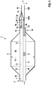
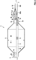
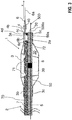
- FIGS. 1 to 3 show embodiments of a catheter device 1 according to the invention for recanalizing an occlusion O in a vessel G (see FIG. FIGS. 6 (A) to 6 (M) ).
- the catheter device then has a catheter shaft 2 extended along a longitudinal axis x, which has a distal end portion 2a, on which a proximal balloon 3 for anchoring the catheter shaft 2 is arranged in the vessel G, which is further configured to expand the occlusion O, the proximal balloon 3 has a balloon interior 30, into which a fluid medium (for example physiological saline solution, contrast medium) can be introduced in order to unfold the proximal balloon 3.
- a fluid medium for example physiological saline solution, contrast medium
- the catheter device 1 furthermore has a distal balloon 4 arranged at the distal end section 2a for the initial widening of the occlusion O, the distal balloon 4 also having a balloon interior 40 into which a fluid medium (eg physiological saline solution) can be deployed for unfolding the proximal balloon 3. Contrast medium) can be introduced.
- the device 1 furthermore has a guide wire lumen 5 formed by the catheter shaft 2 and a guide wire 500 which can be guided in the guide wire lumen 5, the catheter shaft 2 having an opening 20 at the distal end section 2a, via which the guide wire 500 can be led out of the guide wire lumen 5 and out of the catheter shaft 2 is.
- the opening 20 is arranged such that the guide wire 500 extends beyond the distal balloon 4 with a section 500a of the guide wire 500 led out of the guide wire lumen 5 via the opening 20, and in particular can be introduced past the distal balloon into the occlusion is to guide the catheter shaft 2 to the destination.
- the opening 20 is arranged along the longitudinal axis x of the catheter shaft 2 between a distal end 3a of the proximal balloon and a proximal end 4b of the distal balloon 4.
- the guidewire 500 may have a diameter of 0.36 mm, with the inner diameter of the guidewire lumen 5 being made larger, so that the guidewire 500 can slide well in the guidewire lumen 5.
- the catheter device 1 preferably has a longitudinally extended guide element 6 which is separately formed relative to the guide wire 500 and which, in particular, is designed to be radiopaque and projects from the distal balloon 4 with a distal end section 6a.
- the distal end portion 6a may have a length (along the longitudinal axis x) in the range of 2 mm to 10 mm.
- the guide element 6 extends in particular along the longitudinal axis x through the balloon interior 40 of the distal balloon 4, wherein that distal end section 6a of the guide element 6 is led out of the distal balloon 4 at a distal end 4a of the distal balloon 4 out of the distal balloon 4.
- the wire or the guide element 6 according to one embodiment have a diameter of 0.1 mm.
- the distal balloon 4 at 6 atm may have a diameter D2 in the range of 1.0 mm to 2.0 mm.
- the diameter D2 is smaller than the diameter D1 of the fully dilated or unfolded proximal balloon 3.
- the distal balloon 4 may have a length in the range from 2 mm to 10 mm along the longitudinal axis x.
- a double wall thickness of the distal balloon 4 may be in the range of 0.02 mm to 0.04 mm.
- the profile diameter of the distal balloon 4 may further be less than or equal to 0.2 mm according to an embodiment (folded on the guide member 6 which has a diameter of 0.1 mm).
- the distal balloon 4 may be made of one of the following materials: polyamide, in particular PA12, polyethylene terephthalate, polyurethane or polyether block amides such as Pebax (trade name). Furthermore, the distal balloon may have a coating on its outside which is hydrophilic or hydrophobic.
- the guide wire lumen 5 of the catheter shaft 2 is surrounded by a wall 50.
- the catheter device 1 has at least one x-ray marker 8 which is arranged in the balloon interior 30 of the proximal balloon 3 on a wall 50 which surrounds the guide wire lumen 5.
- the wall 50 of the guide wire lumen 5 extends through the balloon interior 30 of the proximal balloon 3 along the longitudinal axis x and thereby frontally the said opening 20 of the distal end portion 2a of the catheter shaft 2 edges.
- the catheter shaft according to the FIGS. 1 to 3 a lumen 7 surrounded by a wall 70, via which, for deployment of the proximal and distal balloons 3, 4, a fluid medium, eg physiological saline or contrast medium, into the balloon interior 30 of the proximal balloon 3 and into the balloon interior 40 of the distal balloon 4 can be introduced.
- a fluid medium eg physiological saline or contrast medium
- the wall 70 of the lumen 7 extends along the longitudinal axis x through the balloon interior 30 of the proximal balloon 3, wherein the lumen 7 is in fluid communication with the balloon interior 40 of the distal balloon 4 or opens into the balloon interior 40 so that the distal balloon 4 can be dilated via the lumen 7.
- the wall 70 of the lumen 7 also has lateral outlet openings 71 arranged in the balloon inner space 30 of the proximal balloon 3, so that the fluid Medium via the outlet opening 71 for deploying the proximal balloon 3 in the balloon interior 30 of the proximal balloon 3 can be introduced.
- a proximal end portion 6b of the extending through the balloon interior 40 of the distal balloon 4 guide member 6 is fixed to the wall 70 of the lumen 7 via an example cohesive connection 6c.
- FIG. 2 shows an alternative embodiment, in which case the wall 70 of the lumen 7 ends at the proximal end 3b of the proximal balloon or the lumen 7 opens into the balloon interior 30 of the proximal balloon 3.
- the balloon interior 30 of the proximal balloon 3 is in fluid communication with the balloon interior 40 of the distal balloon 4, so that the distal balloon 4 can be dilated or inflated via the proximal balloon 3.
- the proximal end portion 6b of the guide member 6 is connected to the wall 50 of the guide wire lumen 5 via an example cohesive connection 6d.
- FIG. 3 1 shows a further embodiment of a catheter device according to the invention, in which case the wall 70 of the lumen 7 also extends through the balloon interior 30 of the proximal balloon 3, but ends along the longitudinal axis x in front of the distal end 3a of the proximal balloon 3, wherein an end outlet opening 72 the wall 70 facing the distal balloon 4 and is fluidly connected thereto via the circumferential distal end 3a of the proximal balloon 3.
- the proximal end section 6b of the guide element / wire 6 projects into the distal end 3a of the proximal balloon 3 and is connected to the wall 50 of the guide wire lumen 5 via, for example, a cohesive connection 6d.
- a proximal end 4b of the distal balloon 4 is connected, on the one hand, to the distal end 3a of the proximal balloon 3 via an eg integral connection 4d and, on the other hand, via an eg cohesive connection 4c to a distal end 50a of the wall 50 of the guide wire lumen 5.
- the distal end 50a of the wall 50 of the guidewire lumen may further via
- a cohesive connection 5c be connected to the distal end 3a of the proximal balloon 3.
- the proximal end 3b of the proximal balloon 3 is connected to the shaft 2 or the wall 50 of the guide wire lumen and / or the wall 70 of the lumen 7 via an eg cohesive connection 3c.
- the catheter shaft 2 can enclose or limit the lumen 7 or the guide wire lumen 5 in various ways.
- the FIGS. 4 and 5 show two principal possibilities, both in the in the FIGS. 1 to 3 shown embodiments can be used.
- the guide wire lumen 5 and the lumen 7 may be adjacent to each other in the catheter shaft 2.
- the two walls 50 and 70 are correspondingly connected to each other along the longitudinal axis x or formed integrally with each other.
- the lumen 7 and the guidewire lumen 5 according to FIG. 5 be arranged coaxially with each other, wherein the guide wire lumen 5 is surrounded by the lumen 7.
- the wall 50 of the guide wire lumen 5 in this case extends in the lumen 7 surrounding the outer wall 70.
- FIGS. 6 (A) to 6 (M) show by way of example the use of a catheter device 1 according to the invention (for example, in the manner of FIG FIGS. 1 to 3 ) for recanalizing a total occlusion O of a vessel G.
- the guide wire 500 of the catheter device 1 is passed through the occlusion O (cf. Fig. 6 (B) ).
- the catheter shaft 2 of the device 1 is then positioned in the vessel or the artery G (cf. Fig. 6 (C) ).
- the guidewire 500 is withdrawn (see FIG. Fig. 6 (D) ) and the distal balloon 4 is positioned with respect to the occlusion O (cf. Fig. 6 (E) ) and introduced into this (cf. Fig. 6 (F) ).
- the proximal balloon 3 and the distal balloon 4 are inflated to dilate the occlusion O (see FIG. Fig. 6 (G) ).
- the proximal balloon 3 serves to anchor the catheter shaft 2 in the vessel G.
- the two balloons 3, 4 are deflated and partially introduced over the guide wire 500 and the elongated guide member 6 in the constriction O (see. Fig. 6 (H) ). Subsequently, the two balloons 3, 4 are dilated, wherein the distal balloon 4 expands the occlusion O more and the proximal balloon 3 in turn ensures anchoring of the shaft 2 in the vessel G (see. Fig. 6 (I) ).
- both balloons 3, 4 deflated and he proximal balloon 3 is inserted centrally into the occlusion O and then dilated (see. Fig. 6 (M) ) to widen the vessel G at the site of occlusion O to the final diameter.
- the device 1 according to the invention advantageously permits recanalization of a CTO by means of a single device 1, which saves time during the procedure and correspondingly reduces the risk for the patient.
Landscapes
- Health & Medical Sciences (AREA)
- Life Sciences & Earth Sciences (AREA)
- Heart & Thoracic Surgery (AREA)
- Veterinary Medicine (AREA)
- Public Health (AREA)
- General Health & Medical Sciences (AREA)
- Engineering & Computer Science (AREA)
- Animal Behavior & Ethology (AREA)
- Biomedical Technology (AREA)
- Vascular Medicine (AREA)
- Hematology (AREA)
- Anesthesiology (AREA)
- Pulmonology (AREA)
- Biophysics (AREA)
- Child & Adolescent Psychology (AREA)
- Surgery (AREA)
- Orthopedic Medicine & Surgery (AREA)
- Nuclear Medicine, Radiotherapy & Molecular Imaging (AREA)
- Medical Informatics (AREA)
- Molecular Biology (AREA)
- Media Introduction/Drainage Providing Device (AREA)
Abstract
Description
- Die Erfindung betrifft eine Kathetereinrichtung (1) zum Rekanalisieren einer Okklusion (O) in einem Gefäß (G), mit einem am distalen Endabschnitt (2a) angeordneten proximalen Ballon (3) zum Verankern des Katheterschafts (2) in dem Gefäß (G) sowie zum Aufweiten der Okklusion (O) und einem am distalen Endabschnitt (2a) angeordneten distalen Ballon (4) zum Aufweiten der Okklusion (O).
- Derartige Kathetereinrichtungen werden insbesondere zum Rekanalisieren bzw. Wiedereröffnen eines chronischen, im Wesentlichen vollständigen Verschlusses (Chronic Total Occlusion oder kurz CTO) eines Gefäßes eines Patienten verwendet.
- Derartige CTOs kommen bei ca. 20% aller Patienten im Herzkatheter-Labor vor. Die durchschnittliche Interventionsdauer liegt in der Regel bei etwa zwei bis 2,5 Stunden. Die Anzahl der verwendeten Führungsdrähte, Ballon-Katheter und Stents ist dabei regelmäßig größer als bei typischen perkutanen Koronarinterventionen (PCI), die keinen CTO betreffen.
- Zur Behandlung bzw. Rekanalisierung von chronischen Totalverschlüssen (CTOs) ist aus dem Stand der Technik gemäß
WO2007/100365A1 z.B. eine Kathetereinrichtung bekannt, die zwei hintereinander angeordnete Ballons aufweist, durch die sich ein Führungsdraht hindurch erstreckt, der zum Positionieren der beiden Ballons vor der Okklusion verwendet wird, wobei der Führungsdraht zunächst durch den Verschluss geführt wird. - Bei derartigen Systemen kann sich das zum Aufnehmen des Führungsdrahts in den beiden Ballons vorgesehene Führungsdrahtlumen als nachteilig erweisen, da hierfür ein entsprechender Bauraum vorgesehen werden muss, so dass die Einrichtung einen vergleichsweise großen Durchmesser im Bereich der Ballone aufweist.
- Ferner kommt es bei derartigen Ballonsystemen regelmäßig zu Rückstoßeffekten während der Balloninflation, da der führende (distale Ballon) beim Entfalten/Dilatieren im Durchmesser zunimmt und daher tendenziell aus der verengten Stelle herausgedrückt wird.
- Hiervon ausgehend liegt der vorliegenden Erfindung daher die Aufgabe zugrunde, eine Kathetereinrichtung bereitzustellen, die hinsichtlich der oben geschilderten Problematik verbessert ist.
- Diese Aufgabe wird durch eine Kathetereinrichtung mit den Merkmalen des Anspruchs 1 gelöst.
- Vorteilhafte Ausgestaltungen sind in den Unteransprüchen angegeben und werden nachfolgend beschrieben.
- Demgemäß wird eine Kathetereinrichtung zum Rekanalisieren einer Okklusion (insbesondere CTO) in einem Gefäß vorgeschlagen, mit:
- einem entlang einer Längsachse erstreckten Katheterschaft, der einen distalen Endabschnitt aufweist,
- einem am distalen Endabschnitt angeordneten proximalen Ballon zum Verankern des Katheterschafts in dem Gefäß sowie zum Aufweiten der Okklusion, der am distalen Endabschnitt des Katheterschafts angeordnet ist, wobei der proximale Ballon einen Balloninnenraum aufweist, in den zum Entfalten des proximalen Ballons ein fluides Medium einleitbar ist,
- einem am distalen Endabschnitt angeordneten distalen Ballon zum initialen Aufweiten der Okklusion, wobei der distale Ballon einen Balloninnenraum aufweist, in den zum Entfalten des proximalen Ballons ein fluides Medium einleitbar ist, und
- einem vom Katheterschaft umgebenen Führungsdrahtlumen sowie einem im Führungsdrahtlumen führbaren Führungsdraht, wobei der Katheterschaft am distalen Endabschnitt eine mit dem Führungsdrahtlumen kommunizierende Öffnung aufweist, über die der Führungsdraht aus dem Führungsdrahtlumen sowie aus dem Katheterschaft herausführbar ist.
- Erfindungsgemäß ist nun vorgesehen, dass die Öffnung so angeordnet ist, dass der Führungsdraht mit einem über die Öffnung aus dem Führungsdrahtlumen herausgeführten Abschnitt des Führungsdrahtes außerhalb des distalen Ballons verläuft sowie insbesondere außen am distalen Ballon vorbeiführbar ist, so dass der Führungsdraht insbesondere am distalen Ballon vorbei in die Okklusion einführbar ist, um den Katheterschaft insbesondere bezüglich der Okklusion zu positionieren. Das Führungsdrahtlumen durchläuft dabei den distalen Endabschnitt, wodurch das Führungsdrahtlumen innerhalb des proximalen Ballons bzw durch den proximalen Ballon verläuft, aber nicht den distalen Ballon durchläuft.
- Gemäß einer Ausführungsform ist diesbezüglich vorgesehen, dass die Öffnung entlang Längsachse des Katheterschafts zwischen dem Balloninnenraum des proximalen Ballons und dem Balloninnenraum des distalen Ballons angeordnet ist. Insbesondere kann die Öffnung entlang der besagten Längsachse am distalen Ende des proximalen Ballons vorgesehen sein oder zwischen dem distalen Ende des proximalen Ballons und einem proximalen Ende des distalen Ballons. Die Öffnung ist dabei bevorzugt im oder nah am axialen Zentrum des proximalen Ballon angeordnet. Die Öffnung ist daher nicht in der Peripherie oder an der Außenseite des proximalen Ballons angeordnet. Eine solche Anordnung ermöglicht es sowohl über die Verlängerung des Führungsdrahtes über die Öffnung hinaus mit dem Führungsdraht als auch durch das Führungselement die Okklusion zu öffnen.
- Wenn im Rahmen der vorliegenden Erfindung von einer proximalen Komponente oder einem proximalen Bereich und einer entsprechenden distalen Komponente bzw. einem distalen Bereich die Rede ist, so bedeutet das, dass die distale Komponente bzw. der distale Bereich entlang des Verlaufs des Katheterschafts weiter von einem Bediener der Kathetereinrichtung entfernt ist, als die proximale Komponente bzw. der proximale Bereich. Bei dem Bereich kann es sich z.B. um einen Endabschnitt oder ein Ende einer Komponente der Kathetereinrichtung handeln.
- Aufgrund der erfindungsgemäßen Gestaltung der Kathetereinrichtung besteht die Möglichkeit, den distalen Ballon verhältnismäßig klein auszugestalten, da dieser das Führungsdrahtlumen nicht mehr beherbergen muss.
- Der distale Ballon weist gemäß einer Ausführungsform der Erfindung vorzugsweise einen Durchmesser auf, der im entfalteten Zustand des distalen Ballons wesentlich kleiner ist als der Durchmesser des entfalteten proximalen Ballons. Der distale Ballon wird daher auch als Mikroballon bezeichnet. Der Durchmesser des proximalen Ballons ist vorzugsweise insbesondere so ausgelegt, dass sich der proximale Ballon in einem entfalteten Zustand an die Gefäßwand des Patienten zum Verankern des Katheterschafts anlegen kann. In besonderen Ausführungsformen ist der Durchmesser des proximalen Ballon im entfalteten Zustand vorzugsweise mehr als doppelt so groß, weiter bevorzugt mehr als 4-fach so groß und am meisten bevorzugt mehr als 10-fach so groß wie der Durchmesser der distalen Ballons im entfalteten Zustand. Ferner ist es bevorzugt, wenn der distale Ballon rigider ausgelegt ist als der proximale Ballon.
- Zum Rekanalisieren der CTO kann die Kathetereinrichtung bzw. der Katheterschaft über den Führungsdraht in den Körper bzw. das betroffene Gefäß des Patienten eingeführt und positioniert werden. Danach wird der Führungsdraht zurückgezogen und der distale Ballon wird in die Okklusion geführt. Die gleichzeitige Dilatation des distalen bzw. Mikroballons sowie des proximalen Ballons sprengt die Okklusion am Eingang. In weiteren Schritten wird der proximale Ballon deflatiert, vorwärts in die Okklusion eingeführt und wieder dilatiert, bis eine vollständige Öffnung des Gefäßes bzw. eine Rekanalisierung der Okklusion erreicht worden ist.
- Mittels der erfindungsgemäßen Einrichtung wird eine CTO-Rekanalisierung vereinfacht, da der distale Ballon verhältnismäßig dünn ist und entsprechend leichter in die Okklusion bewegbar ist. Weiterhin kann ein beim Dilatieren des distalen Ballons erzeugter Rückstoß gut mit dem proximalen Ballon aufgefangen werden, da dieser auf der Innenwand des Gefäßes verankerbar ist (siehe oben).
- Weiterhin ist gemäß einer Ausführungsform der Erfindung vorgesehen, dass die Kathetereinrichtung ein zu dem Führungsdraht separat ausgebildetes längserstrecktes Führungselement aufweist, das mit einem distalen Endabschnitt von dem zweiten Ballon in distaler Richtung absteht.
- Weiterhin ist gemäß einer Ausführungsform der Erfindung vorgesehen, dass sich das Führungselement durch den Balloninnenraum des distalen Ballons hindurch erstreckt, wobei jener distale Endabschnitt des Führungselements an einem distalen Ende des distalen Ballons aus dem distalen Ballon herausgeführt ist.
- Gemäß einer Ausführungsform der Erfindung kann das Führungselement z.B. durch einen Draht gebildet ist sein. Der Draht kann einen röntgensichtbaren Kern aufweisen, der aus Platin oder aus einer Platinlegierung geformt ist, wobei der Kern mit einer Cobalt-Chrom-Legierung beschichtet sein kann. Weiterhin kann das Führungselement bzw. der Draht einen Röntgenmarker aufweisen. Weiterhin ist in einer Ausführungsform das Führungselement von der Spitze des distalen Ballons zum aus dem Führungsdrahtlumen herausgeführten Abschnitt, in dem der Führungsdraht außerhalb des distalen Ballons distal zur Öffnung des distalen Endabschnittes verlaufen kann, hingeneigt.
- Weiterhin ist gemäß einer Ausführungsform der Erfindung vorgesehen, dass das Führungsdrahtlumen des Katheterschafts von einer Wandung umgeben ist. Hierbei ist gemäß einer Ausführungsform vorgesehen, dass sich die Wandung des Führungsdrahtlumens durch den Balloninnenraum des proximalen Ballons hindurch erstreckt.
- Weiterhin ist gemäß einer Ausführungsform der Erfindung vorgesehen, dass der Katheterschaft ein von einer Wandung umgebenes Lumen (Inflationslumen) aufweist, über das zum, insbesondere gleichzeitigen, Entfalten des proximalen und des distalen Ballons ein fluides Medium in den Balloninnenraum des proximalen Ballons und in den Balloninnenraum des distalen Ballons einleitbar ist. Es ist also vorgesehen, dass der proximale Ballon und der distale Ballon über ein einzelnes (Inflations)lumen mit einem fluiden Medium inflatierbar sind.
- Gemäß einer Ausführungsform der Erfindung ist vorgesehen, dass das Lumen in den Balloninnenraum des proximalen Ballons mündet, wobei der Balloninnenraum des distalen Ballons über den Balloninnenraum des proximalen Ballons mit dem Lumen in Strömungsverbindung steht.
- Ein solcher Aufbau hat den Vorteil, dass im dem Moment, in dem man das Führungselement und den distalen Ballon weiter in die Okklusion einführen möchte, das Verankern im Gefäß durch den proximalen Ballon gelöst werden muss, wodurch auch der distale Ballon, der in die Okklusion eingeführt werden soll, an Volumen verliert und leichter vorgeschoben werden kann. Es ist daher nicht nötig, erst die Verankerung durch den proximalen Ballon zu lösen und danach das Volumen des distalen Ballon einzustellen wie dies bei einer Ausgestaltung notwendig wäre, bei der separate (Inflations)lumen für den distalen und den proximalen Ballon vorliegen.
- Weiterhin ist gemäß einer Ausführungsform der Erfindung vorgesehen, dass sich die Wandung des Lumens durch den Balloninnenraum des proximalen Ballons hindurch erstreckt, wobei das Lumen mit dem Balloninnenraum des distalen Ballons in Strömungsverbindung steht, und wobei die Wandung des Lumens zumindest eine im Balloninnerraum des proximalen Ballons angeordnete laterale Auslassöffnung aufweist, über die ein fluides Medium zum Entfalten des proximalen Ballons in den Balloninnenraum des proximalen Ballons einleitbar ist.
- Weiterhin ist gemäß einer Ausführungsform vorgesehen, dass ein proximaler Endabschnitt des Führungselements mit der Wandung des Führungsdrahtlumens verbunden ist. Dies gilt insbesondere für den Fall, dass sich das Lumen nicht durch den Balloninnenraum des proximalen Ballons hindurch erstreckt bzw. nicht vollständig bis zum distalen Ballon erstreckt.
- Gemäß einer alternativen Ausführungsform der Erfindung ist vorgesehen, dass der proximale Endabschnitt des Führungselements mit der Wandung des Lumens verbunden ist. Dies kann insbesondere der Fall ein, wenn sich das besagte Lumen bzw. die Wandung des Lumens durch den Balloninnenraum des proximalen Ballons hindurch erstreckt. Weiterhin ist gemäß einer Ausführungsform der Erfindung vorgesehen, dass ein proximales Ende des distalen Ballons mit der Wandung des Führungsdrahtlumens und/oder mit der Wandung des Lumens verbunden ist.
- Weiterhin ist gemäß einer Ausführungsform der Erfindung vorgesehen, dass sich das Lumen und das Führungsdrahtlumen nebeneinander im Katheterschaft entlang der Längsachse erstrecken.
- Gemäß einer alternativen Ausführungsform kann ebenfalls vorgesehen sein, dass das Lumen und das Führungsdrahtlumen koaxial zueinander angeordnet sind, wobei das Führungsdrahtlumen von dem besagten Lumen umgeben ist. In diesem Fall umschließt die Wandung des Lumens die Wandung des Führungsdrahtlumens.
- Gemäß einer weiteren Ausführungsform der Erfindung ist vorgesehen, dass die Kathetereinrichtung mindestens einen Röntgenmarker für den proximalen Ballon aufweist, der im Balloninnenraum des proximalen Ballons an der Wandung des Führungsdrahtlumens angeordnet ist.
- Weitere Merkmale und Vorteile der Erfindung sollen bei der Figurenbeschreibung von Ausführungsbeispielen der Erfindung anhand der Figuren erläutert werden. Es zeigen:
- Fig. 1
- eine schematische Schnittansicht einer Ausführungsform einer erfindungsgemäßen Kathetereinrichtung;
- Fig. 2
- eine schematische Schnittansicht einer weiteren Ausführungsform einer erfindungsgemäßen Kathetereinrichtung;
- Fig. 3
- eine schematische Schnittansicht einer weiteren Ausführungsform einer erfindungsgemäßen Kathetereinrichtung;
- Fig. 4
- eine Schnittdarstellung einer Ausführungsform des Katheterschafts der Kathetereinrichtung;
- Fig. 5
- eine Schnittdarstellung einer alternativen Ausführungsform des Katheterschafts der Kathetereinrichtung; und
- Fig. 6
- zeigt eine mögliche Rekanalisierung einer totalen Okklusion (CTO) unter Verwendung einer erfindungsgemäßen Kathetereinrichtung.
- Die
Figuren 1 bis 3 zeigen Ausführungsformen einer erfindungsgemäßen Kathetereinrichtung 1 zum Rekanalisieren einer Okklusion O in einem Gefäß G (vgl.Figuren 6(A) bis 6(M) ). Die Kathetereinrichtung weist danach einen entlang einer Längsachse x erstreckten Katheterschaft 2 auf, der einen distalen Endabschnitt 2a aufweist, an dem ein proximaler Ballon 3 zum Verankern des Katheterschafts 2 in dem Gefäß G angeordnet ist, der ferner zum Aufweiten der Okklusion O konfiguriert ist, wobei der proximale Ballon 3 einen Balloninnenraum 30 aufweist, in den zum Entfalten des proximalen Ballons 3 ein fluides Medium (z.B. physiologische Kochsalzlösung, Kontrastmittel) einleitbar ist. Die Kathetereinrichtung 1 weist weiterhin einen am distalen Endabschnitt 2a angeordneten distalen Ballon 4 zum initialen Aufweiten der Okklusion O auf, wobei der distale Ballon 4 ebenfalls einen Balloninnenraum 40 aufweist, in den zum Entfalten des proximalen Ballons 3 ebenfalls ein fluides Medium (z.B. physiologische Kochsalzlösung, Kontrastmittel) einleitbar ist. Die Einrichtung 1 weist weiterhin ein vom Katheterschaft 2 gebildetes Führungsdrahtlumen 5 auf sowie einen im Führungsdrahtlumen 5 führbaren Führungsdraht 500, wobei der Katheterschaft 2 am distalen Endabschnitt 2a eine Öffnung 20 aufweist, über die der Führungsdraht 500 aus dem Führungsdrahtlumen 5 sowie aus dem Katheterschaft 2 herausführbar ist. - Erfindungsgemäß ist vorgesehen, dass die Öffnung 20 so angeordnet ist, dass der Führungsdraht 500 mit einem über die Öffnung 20 aus dem Führungsdrahtlumen 5 herausgeführten Abschnitt 500a des Führungsdrahtes 500 außerhalb des distalen Ballons 4 verläuft und dabei insbesondere an dem distalen Ballon vorbei in die Okklusion einführbar ist, um den Katheterschaft 2 zum Zielort zu führen.
- Insbesondere ist die Öffnung 20 entlang der Längsachse x des Katheterschafts 2 zwischen einem distalen Ende 3a des proximalen Ballons und einem proximalen Ende 4b des distalen Ballons 4 angeordnet.
- Der Führungsdraht 500 kann beispielsweise einen Durchmesser von 0,36mm aufweisen, wobei der Innendurchmesser des Führungsdrahtlumens 5 größer ausgestaltet ist, so dass der Führungsdraht 500 gut im Führungsdrahtlumen 5 gleiten kann.
- Zum Einführen bzw. Positionieren des distalen Ballons 4 in die Okklusion O weist die Kathetereinrichtung 1 vorzugsweise ein zu dem Führungsdraht 500 separat ausgebildetes längserstrecktes Führungselement 6 aufweist, das insbesondere röntgensichtbar ausgebildet und das mit einem distalen Endabschnitt 6a von dem distalen Ballon 4 absteht. Gemäß einer Ausführungsform kann der distale Endabschnitt 6a eine Länge (entlang der Längsachse x) im Bereich von 2 mm bis 10 mm aufweisen. Das Führungselement 6 erstreckt sich insbesondere entlang der Längsachs x durch den Balloninnenraum 40 des distalen Ballons 4 hindurch, wobei jener distale Endabschnitt 6a des Führungselements 6 aus dem distalen Ballon 4 an einem distalen Ende 4a des distalen Ballons 4 aus dem distalen Ballon 4 herausgeführt ist.
- Weiterhin kann der Draht bzw. das Führungselement 6 gemäß einer Ausführungsform einen Durchmesser von 0,1mm aufweisen.
- Weiterhin kann der distale Ballon 4 gemäß einer Ausführungsform bei 6 atm einen Durchmesser D2 im Bereich von 1,0 mm bis 2,0 mm aufweisen. Diesbezüglich ist weiterhin vorgesehen, dass der Durchmesser D2 kleiner ist als der Durchmesser D1 des vollständig dilatierten bzw. entfalteten proximalen Ballons 3.
- Weiterhin kann der distale Ballon 4 gemäß einer Ausführungsform entlang der Längsachse x eine Länge im Bereich von 2 mm bis 10 mm aufweisen.
- Weiterhin kann eine doppelte Wandstärke des distalen Ballons 4 gemäß einer Ausführungsform im Bereich von 0,02 mm bis 0,04 mm liegen. Der Profildurchmesser des distalen Ballons 4 kann des Weiteren gemäß einer Ausführungsform (gefaltet auf das Führungselement 6 das einen Durchmesser von 0,1mm aufweist) kleiner oder gleich 0,2 mm sein.
- Weiterhin kann der distale Ballon 4 gemäß einer Ausführungsform aus einem der folgenden Materialien gefertigt sein: Polyamid, insbesondere PA12, Polyethylenterephthalat, Polyurethan oder Polyether Blockamide wie Pebax (Markenname). Weiterhin kann der distale Ballon eine Beschichtung auf seiner Außenseite aufweisen, die hydrophil oder hydrophob ist.
- Weiterhin ist vorgesehen, dass das Führungsdrahtlumen 5 des Katheterschafts 2 von einer Wandung 50 umgeben ist. Zum Verfolgen des proximalen Ballons 3 kann des Weiteren vorgesehen sein, dass die Kathetereinrichtung 1 mindestens einen Röntgenmarker 8 aufweist, der im Balloninnenraum 30 des proximalen Ballons 3 an einer Wandung 50 angeordnet ist, die das Führungsdrahtlumen 5 umgibt. Weiterhin ist vorgesehen, dass sich die Wandung 50 des Führungsdrahtlumens 5 durch den Balloninnenraum 30 des proximalen Ballons 3 entlang der Längsachse x hindurch erstreckt und dabei stirnseitig die besagte Öffnung 20 des distalen Endabschnitts 2a des Katheterschafts 2 berandet.
- Weiterhin weist der Katheterschaft gemäß den
Figuren 1 bis 3 ein von einer Wandung 70 umgebenes Lumen 7 auf, über das zum Entfalten des proximalen und des distalen Ballons 3, 4 ein fluides Medium, z.B. physiologische Kochsalzlösung oder Kontrastmittel, in den Balloninnenraum 30 des proximalen Ballons 3 und in den Balloninnenraum 40 des distalen Ballons 4 einleitbar ist. - Gemäß der in der
Figur 1 gezeigten Ausführungsform ist vorgesehen, dass sich die Wandung 70 des Lumens 7 entlang der Längsachse x durch den Balloninnenraum 30 des proximalen Ballons 3 hindurch erstreckt, wobei das Lumen 7 mit dem Balloninnenraum 40 des distalen Ballons 4 in Strömungsverbindung steht bzw. in den Balloninnenraum 40 mündet, so dass der distale Ballon 4 über das Lumen 7 dilatierbar ist. Zum Dilatieren des proximalen Ballons 3 weist die Wandung 70 des Lumens 7 ferner im Balloninnerraum 30 des proximalen Ballons 3 angeordnete laterale Auslassöffnungen 71 auf, so dass das fluide Medium über die Auslassöffnung 71 zum Entfalten des proximalen Ballons 3 auch in den Balloninnenraum 30 des proximalen Ballons 3 einleitbar ist. - Weiterhin ist gemäß
Figur 1 vorgesehen, dass ein proximaler Endabschnitt 6b des sich durch den Balloninnenraum 40 des distalen Ballons 4 erstreckende Führungselement 6 an der Wandung 70 des Lumens 7 über eine z.B. stoffschlüssige Verbindung 6c festgelegt ist. -
Figur 2 zeigt demgegenüber eine alternative Ausführungsform, wobei hier die Wandung 70 des Lumens 7 am proximalen Ende 3b des proximalen Ballons endet bzw. das Lumen 7 in den Balloninnenraum 30 des proximalen Ballons 3 mündet. Der Balloninnenraum 30 des proximalen Ballons 3 steht dabei mit dem Balloninnenraum 40 des distalen Ballons 4 in Strömungsverbindung, so dass der distale Ballon 4 über den proximalen Ballon 3 dilatierbar bzw. inflatierbar ist. Bei der Ausführungsform gemäßFigur 2 ist im Unterschied zurFigur 1 vorgesehen, dass der proximale Endabschnitt 6b des Führungselements 6 mit der Wandung 50 des Führungsdrahtlumens 5 über eine z.B. stoffschlüssige Verbindung 6d verbunden ist. -
Figur 3 zeigt eine weitere Ausführungsform einer erfindungsgemäßen Kathetereinrichtung, wobei sich hier die Wandung 70 des Lumens 7 ebenfalls durch den Balloninnenraum 30 des proximalen Ballons 3 hindurch erstreckt, jedoch entlang der Längsachse x vor dem distalen Ende 3a des proximalen Ballons 3 endet, wobei eine stirnseitige Auslassöffnung 72 der Wandung 70 dem distalen Ballon 4 zugewandt ist und mit diesem über das umlaufende distale Ende 3a des proximalen Ballons 3 strömungstechnisch verbunden ist. Der proximale Endabschnitt 6b des Führungselements/Drahts 6 steht hierbei in das distale Ende 3a des proximalen Ballons 3 hinein und ist über eine z.B. stoffschlüssige Verbindung 6d mit der Wandung 50 des Führungsdrahtlumens 5 verbunden. - Weiterhin ist insbesondere vorgesehen, dass ein proximales Ende 4b des distalen Ballons 4 einerseits über eine z.B. stoffschlüssige Verbindung 4d mit dem distalen Ende 3a des proximalen Ballons 3 verbunden ist sowie andererseits über eine z.B. stoffschlüssige Verbindung 4c mit einem distalen Ende 50a der Wandung 50 des Führungsdrahtlumens 5. Das distale Ende 50a der Wandung 50 des Führungsdrahtlumens kann des Weiteren über eine z.B. stoffschlüssige Verbindung 5c mit dem distalen Ende 3a des proximalen Ballons 3 verbunden sein. Schließlich ist insbesondere das proximale Ende 3b des proximalen Ballons 3 über eine z.B. stoffschlüssige Verbindung 3c mit dem Schaft 2 bzw. der Wandung 50 des Führungsdrahtlumens und/oder der Wandung 70 des Lumens 7 verbunden.
- Der Katheterschaft 2 kann auf verschiedene Weisen das Lumen 7 bzw. das Führungsdrahtlumen 5 umschließen bzw. begrenzen. Die
Figuren 4 und 5 zeigen zwei prinzipielle Möglichkeiten, die beide bei den in denFiguren 1 bis 3 gezeigten Ausführungsformen verwendet werden können. GemäßFigur 4 können das Führungsdrahtlumen 5 und das Lumen 7 benachbart nebeneinander her im Katheterschaft 2 erstreckt sein. Die beiden Wandungen 50 bzw. 70 sind entsprechend entlang der Längsachse x miteinander verbunden oder integral miteinander ausgebildet. - Alternativ hierzu können das Lumen 7 und das Führungsdrahtlumen 5 gemäß
Figur 5 koaxial zueinander angeordnet sein, wobei das Führungsdrahtlumen 5 vom Lumen 7 umgeben ist. Die Wandung 50 des Führungsdrahtlumens 5 erstreckt sich hierbei in dem von der äußeren Wandung 70 umgebenden Lumen 7. - Die
Figuren 6(A) bis 6(M) zeigen exemplarisch die Verwendung einer erfindungsgemäßen Kathetereinrichtung 1 (z.B. nach Art derFiguren 1 bis 3 ) zum Rekanalisieren einer totalen Okklusion O eines Gefäßes G. - Nach initialer Beurteilung der Verengung (CTO) O (vgl.
Fig. 6(A) ) wird der Führungsdraht 500 der Kathetereinrichtung 1 durch die Okklusion O hindurchgeführt (vgl.Fig. 6(B) ). Mittels des Führungsdrahts 500 wird der Katheterschaft 2 der Einrichtung 1 sodann in dem Gefäß bzw. der Arterie G positioniert (vgl.Fig. 6(C) ). - Nach dem Positionieren des Katheterschafts 2 wird der Führungsdraht 500 zurückgezogen (vgl.
Fig. 6(D) ) und der distale Ballon 4 wird bezüglich der Okklusion O positioniert (vgl.Fig. 6(E) ) und in diese eingeführt (vgl.Fig. 6(F) ). - Sodann werden der proximale Ballon 3 und der distale Ballon 4 inflatiert, um die Okklusion O aufzuweiten (vgl.
Fig. 6(G) ). Hierbei dient der proximale Ballon 3 zum Verankern des Katheterschafts 2 im Gefäß G. - Hiernach werden die beiden Ballons 3, 4 deflatiert und teilweise über den Führungsdraht 500 und das längserstreckte Führungselement 6 in die Verengung O einführt (vgl.
Fig. 6(H) ). Anschließend werden die beiden Ballons 3, 4 dilatiert, wobei der distale Ballon 4 die Okklusion O stärker aufweitet und der proximale Ballon 3 wiederum für eine Verankerung des Schafts 2 im Gefäß G sorgt (vgl.Fig. 6(I) ). - Anschließend werden gemäß
Fig. 6(J) die beiden Ballons 3, 4 deflatiert und weiter in die Okklusion O eingeführt. Hiernach werden die beiden Ballons 3, 4 wieder dilatiert um die Läsion O noch stärker aufzuweiten (vgl.Fig. 6(K) ). - Anschließend werden gemäß
Fig. 6(L) beide Ballons 3, 4 deflatiert und er proximale Ballon 3 wird mittig in die Okklusion O eingeführt und sodann dilatiert (vgl.Fig. 6(M) ) um das Gefäß G an der Stelle der Okklusion O auf den Enddurchmesser aufzuweiten. - Die erfindungsgemäße Einrichtung 1 ermöglicht mit Vorteil einer Rekanalisierung einer CTO mittels einer einzigen Einrichtung 1, wodurch beim Eingriff Zeit gespart wird und das Risiko für den Patienten entsprechend herabgesetzt wird.
Claims (15)
- Kathetereinrichtung (1) zum Rekanalisieren einer Okklusion (O) in einem Gefäß (G), mit:- einem entlang einer Längsachse (x) erstreckten Katheterschaft (2), der einen distalen Endabschnitt (2a) aufweist,- einem am distalen Endabschnitt (2a) angeordneten proximalen Ballon (3) zum Verankern des Katheterschafts (2) in dem Gefäß (G) sowie zum Aufweiten der Okklusion (O), wobei der proximale Ballon (3) einen Balloninnenraum (30) aufweist, in den zum Entfalten des proximalen Ballons (3) ein fluides Medium einleitbar ist,- einem am distalen Endabschnitt (2a) angeordneten distalen Ballon (4) zum Aufweiten der Okklusion (O), wobei der distale Ballon (4) einen Balloninnenraum (40) aufweist, in den zum Entfalten des proximalen Ballons (3) ein fluides Medium einleitbar ist, und- einem vom Katheterschaft (2) umgebenen Führungsdrahtlumen (5) sowie einem im Führungsdrahtlumen (5) führbaren Führungsdraht (500), wobei der Katheterschaft (2) am distalen Endabschnitt (2a) eine Öffnung (20) aufweist, über die der Führungsdraht (500) aus dem Führungsdrahtlumen (5) sowie aus dem Katheterschaft (2) herausführbar ist,dadurch gekennzeichnet,
dass die Öffnung (20) so angeordnet ist, dass der Führungsdraht (500) mit einem über die Öffnung (20) aus dem Führungsdrahtlumen (5) herausgeführten Abschnitt (500a) des Führungsdrahtes (500) außerhalb des distalen Ballons (4) verläuft. - Kathetereinrichtung nach Anspruch 1, dadurch gekennzeichnet, dass die Kathetereinrichtung (1) ein zu dem Führungsdraht (500) separat ausgebildetes sowie längserstrecktes Führungselement (6) aufweist, das mit einem distalen Endabschnitt (6a) des Führungselements (6) von dem distalen Ballon (4) absteht.
- Kathetereinrichtung nach Anspruch 2, dadurch gekennzeichnet, dass sich das Führungselement (6) durch den Balloninnenraum (40) des distalen Ballons (4) erstreckt, wobei jener distale Endabschnitt (6a) des Führungselements (6) an einem distalen Ende (4a) des distalen Ballons (4) aus dem distalen Ballon (4) herausgeführt ist.
- Kathetereinrichtung nach Anspruch 2 oder 3, dadurch gekennzeichnet, dass das Führungselement (6) durch einen röntgensichtbaren Draht gebildet ist.
- Kathetereinrichtung nach einem der vorhergehenden Ansprüche, dadurch gekennzeichnet, dass ein Durchmesser (D1) des proximalen Ballons (3) quer zur Längsachse (x) des Katheterschafts (2) in einem vollständig entfalteten Zustand des proximalen Ballons (3) größer ist als ein Durchmesser (D2) des distalen Ballons (4) quer zur Längsachse (x) des Katheterschafts (2) in einem vollständig entfalteten Zustand des distalen Ballons (4).
- Kathetereinrichtung nach einem der vorhergehenden Ansprüche, dadurch gekennzeichnet, dass das Führungsdrahtlumen (5) des Katheterschafts (2) von einer Wandung (50) umgeben ist.
- Kathetereinrichtung nach Anspruch 6, dadurch gekennzeichnet, dass sich die Wandung (50) des Führungsdrahtlumens (5) durch den Balloninnenraum (30) des proximalen Ballons (3) hindurch erstreckt.
- Kathetereinrichtung nach einem der vorhergehenden Ansprüche, dadurch gekennzeichnet, dass der Katheterschaft (2) ein von einer Wandung umgebenes Lumen (7) aufweist, über das zum Entfalten des proximalen und des distalen Ballons (3, 4) ein fluides Medium in den Balloninnenraum (30) des proximalen Ballons (3) und in den Balloninnenraum (40) des distalen Ballons (4) einleitbar ist.
- Kathetereinrichtung nach Anspruch 8, dadurch gekennzeichnet, dass das Lumen (7) in den Balloninnenraum (30) des proximalen Ballons (3) mündet, wobei der Balloninnenraum (40) des distalen Ballons (4) über den Balloninnenraum (30) des proximalen Ballons (3) mit dem Lumen (7) in Strömungsverbindung steht.
- Kathetereinrichtung nach Anspruch 8, dadurch gekennzeichnet, dass sich die Wandung (70) des Lumens (7) durch den Balloninnenraum (30) des proximalen Ballons (3) hindurch erstreckt, wobei das Lumen (7) mit dem Balloninnenraum (40) des distalen Ballons (4) in Strömungsverbindung steht, und wobei die Wandung (70) des Lumens (7) zumindest eine im Balloninnerraum (30) des proximalen Ballons (3) angeordnete laterale Auslassöffnung (71) aufweist, über die ein fluides Medium zum Entfalten des proximalen Ballons (3) in den Balloninnenraum (30) des proximalen Ballons (3) einleitbar ist.
- Kathetereinrichtung nach Anspruch 2 und nach Anspruch 6 oder einem der Ansprüche 6 bis 11 sofern rückbezogen auf Anspruch 6, dadurch gekennzeichnet, dass ein proximaler Endabschnitt (6b) des Führungselements (6) mit der Wandung (50) des Führungsdrahtlumens (5) verbunden ist.
- Kathetereinrichtung nach den Ansprüchen 2 und nach Anspruch 8 oder einem der Ansprüche 10 bis 11 soweit rückbezogen auf Anspruch 9, dadurch gekennzeichnet, dass ein proximaler Endabschnitt (6b) des Führungselements (6) mit der Wandung (70) des Lumens (7) verbunden ist.
- Kathetereinrichtung nach einem der vorhergehenden Ansprüchen, dadurch gekennzeichnet, dass das Lumen (7) und das Führungsdrahtlumen (5) nebeneinander im Katheterschaft (2) erstrecken.
- Kathetereinrichtung nach einem der Ansprüche 1 bis 12, dadurch gekennzeichnet, dass das Lumen (7) und das Führungsdrahtlumen (5) koaxial zueinander angeordnet sind, wobei das Führungsdrahtlumen (5) vom Lumen (7) umgeben ist.
- Kathetereinrichtung nach Anspruch 6 und einem der Ansprüche 7 bis 14 soweit rückbezogen auf Anspruch 6, dadurch gekennzeichnet, dass die Kathetereinrichtung (1) mindestens einen Röntgenmarker (8) aufweist, der im Balloninnenraum (30) des proximalen Ballons (3) an der Wandung (50) des Führungsdrahtlumens (5) angeordnet ist.
Applications Claiming Priority (1)
| Application Number | Priority Date | Filing Date | Title |
|---|---|---|---|
| EP18170549 | 2018-05-03 |
Publications (3)
| Publication Number | Publication Date |
|---|---|
| EP3563899A1 true EP3563899A1 (de) | 2019-11-06 |
| EP3563899B1 EP3563899B1 (de) | 2025-08-27 |
| EP3563899C0 EP3563899C0 (de) | 2025-08-27 |
Family
ID=62110984
Family Applications (1)
| Application Number | Title | Priority Date | Filing Date |
|---|---|---|---|
| EP19168918.1A Active EP3563899B1 (de) | 2018-05-03 | 2019-04-12 | Kathetereinrichtung für eine cto-rekanalisierung |
Country Status (2)
| Country | Link |
|---|---|
| US (1) | US11166734B2 (de) |
| EP (1) | EP3563899B1 (de) |
Citations (4)
| Publication number | Priority date | Publication date | Assignee | Title |
|---|---|---|---|---|
| WO1995016487A1 (en) * | 1993-12-17 | 1995-06-22 | Jang G David | Sliding receptacle catheter systems |
| WO1999007354A2 (en) * | 1997-08-08 | 1999-02-18 | Duke University | Compositions, apparatus and methods for facilitating surgical procedures |
| US20060271090A1 (en) * | 2004-03-04 | 2006-11-30 | Yoav Shaked | Vessel treatment devices |
| WO2007100365A1 (en) * | 2006-03-03 | 2007-09-07 | Boston Scientific Limited | Balloon catheter |
Family Cites Families (6)
| Publication number | Priority date | Publication date | Assignee | Title |
|---|---|---|---|---|
| US4990139A (en) * | 1986-09-10 | 1991-02-05 | Jang G David | Tandem independently inflatable/deflatable multiple diameter balloon angioplasty catheter systems |
| US6682608B2 (en) * | 1990-12-18 | 2004-01-27 | Advanced Cardiovascular Systems, Inc. | Superelastic guiding member |
| US7618451B2 (en) * | 2001-05-25 | 2009-11-17 | Conformis, Inc. | Patient selectable joint arthroplasty devices and surgical tools facilitating increased accuracy, speed and simplicity in performing total and partial joint arthroplasty |
| WO2002007795A2 (en) * | 2000-07-24 | 2002-01-31 | Jeffrey Grayzel | Stiffened balloon catheter for dilatation and stenting |
| US20020072706A1 (en) * | 2000-12-11 | 2002-06-13 | Thomas Hiblar | Transluminal drug delivery catheter |
| US7001420B2 (en) * | 2002-07-01 | 2006-02-21 | Advanced Cardiovascular Systems, Inc. | Coil reinforced multilayered inner tubular member for a balloon catheter |
-
2019
- 2019-04-12 EP EP19168918.1A patent/EP3563899B1/de active Active
- 2019-04-16 US US16/385,583 patent/US11166734B2/en active Active
Patent Citations (4)
| Publication number | Priority date | Publication date | Assignee | Title |
|---|---|---|---|---|
| WO1995016487A1 (en) * | 1993-12-17 | 1995-06-22 | Jang G David | Sliding receptacle catheter systems |
| WO1999007354A2 (en) * | 1997-08-08 | 1999-02-18 | Duke University | Compositions, apparatus and methods for facilitating surgical procedures |
| US20060271090A1 (en) * | 2004-03-04 | 2006-11-30 | Yoav Shaked | Vessel treatment devices |
| WO2007100365A1 (en) * | 2006-03-03 | 2007-09-07 | Boston Scientific Limited | Balloon catheter |
Also Published As
| Publication number | Publication date |
|---|---|
| EP3563899B1 (de) | 2025-08-27 |
| US20190336146A1 (en) | 2019-11-07 |
| US11166734B2 (en) | 2021-11-09 |
| EP3563899C0 (de) | 2025-08-27 |
Similar Documents
| Publication | Publication Date | Title |
|---|---|---|
| DE69825200T2 (de) | Kathetersystem zum Anbringen eines Stent | |
| DE69325303T2 (de) | Schnelles Katheteraustauschersystem | |
| DE69215130T2 (de) | System zum Einführen eines Gefässerweiterungsgerätes | |
| DE60225147T2 (de) | Ballonkatheter und verfahren zu seiner stabilisierung bei der dehnung | |
| DE69232848T2 (de) | Kathetervorrichtung mit Katheter- und Führungsdrahtwechsel | |
| DE69830227T2 (de) | Ballonkatheter zur reparatur abzweigender blutgefässen | |
| DE69921976T2 (de) | Dilations- und Stentzufuhrsystem für abgezweigte Lasionen | |
| DE69533730T2 (de) | Schnellaustausch-zuführungskatheter-system | |
| DE69738235T2 (de) | Hybrider, rohrförmiger katheterführungsdraht | |
| DE3853057T2 (de) | Entfernbare endoarterielle-Vorrichtung, bestimmt für die Reparatur von Ablösungen in arteriellen Wänden. | |
| DE3690224C2 (de) | Gefäßplastische Koronar-Ballon-Sonde | |
| DE602004013288T2 (de) | Dilatationsvorrichtung mit einem ausdehnbaren teil | |
| EP2450010B1 (de) | Ballon-Katheter, insbesondere zum Ausbringen von Medikamenten oder Stents im Bereich einer Stenose | |
| DE60021173T2 (de) | Bifurkationsstenteinführsystem | |
| DE69725324T2 (de) | Dichtung für eine Kathetereinrichtung mit Dilatations- und Okklusionsballon | |
| DE60212340T2 (de) | Führungsdrahtvorrichtung zur vollständigen okklusion | |
| DE60212048T2 (de) | Katheter mit verbesserter distaler Schubfähigkeit | |
| DE69426612T2 (de) | Katheter zum Anbringen eines Stents | |
| DE69521502T2 (de) | Angioplastievorrichtung | |
| DE69129539T2 (de) | Zwei spiralfedern führungsdraht mit strahlundurchlässiger distaler spitze | |
| DE69131805T2 (de) | Leicht auswechselbarer Perfusionskatheter | |
| EP2510972B1 (de) | Kathetervorrichtung | |
| EP3072463B1 (de) | Medizinisches Kit bzw. Set zur Behandlung eines krankhaft veränderten Hohlorgans | |
| EP0446178A2 (de) | Angioplastie-Lichtleiterkatheter für die Stenoseabtragung mit Laserlichtenergie | |
| EP2446918A1 (de) | Ballonkatheter mit einem radial asymmetrisch dilatierbaren Abschnitt |
Legal Events
| Date | Code | Title | Description |
|---|---|---|---|
| PUAI | Public reference made under article 153(3) epc to a published international application that has entered the european phase |
Free format text: ORIGINAL CODE: 0009012 |
|
| STAA | Information on the status of an ep patent application or granted ep patent |
Free format text: STATUS: THE APPLICATION HAS BEEN PUBLISHED |
|
| AK | Designated contracting states |
Kind code of ref document: A1 Designated state(s): AL AT BE BG CH CY CZ DE DK EE ES FI FR GB GR HR HU IE IS IT LI LT LU LV MC MK MT NL NO PL PT RO RS SE SI SK SM TR |
|
| AX | Request for extension of the european patent |
Extension state: BA ME |
|
| STAA | Information on the status of an ep patent application or granted ep patent |
Free format text: STATUS: REQUEST FOR EXAMINATION WAS MADE |
|
| 17P | Request for examination filed |
Effective date: 20200424 |
|
| RBV | Designated contracting states (corrected) |
Designated state(s): AL AT BE BG CH CY CZ DE DK EE ES FI FR GB GR HR HU IE IS IT LI LT LU LV MC MK MT NL NO PL PT RO RS SE SI SK SM TR |
|
| STAA | Information on the status of an ep patent application or granted ep patent |
Free format text: STATUS: EXAMINATION IS IN PROGRESS |
|
| 17Q | First examination report despatched |
Effective date: 20240523 |
|
| GRAP | Despatch of communication of intention to grant a patent |
Free format text: ORIGINAL CODE: EPIDOSNIGR1 |
|
| STAA | Information on the status of an ep patent application or granted ep patent |
Free format text: STATUS: GRANT OF PATENT IS INTENDED |
|
| RIC1 | Information provided on ipc code assigned before grant |
Ipc: A61B 17/22 20060101ALN20250314BHEP Ipc: A61M 25/10 20130101AFI20250314BHEP |
|
| INTG | Intention to grant announced |
Effective date: 20250401 |
|
| GRAS | Grant fee paid |
Free format text: ORIGINAL CODE: EPIDOSNIGR3 |
|
| GRAA | (expected) grant |
Free format text: ORIGINAL CODE: 0009210 |
|
| STAA | Information on the status of an ep patent application or granted ep patent |
Free format text: STATUS: THE PATENT HAS BEEN GRANTED |
|
| AK | Designated contracting states |
Kind code of ref document: B1 Designated state(s): AL AT BE BG CH CY CZ DE DK EE ES FI FR GB GR HR HU IE IS IT LI LT LU LV MC MK MT NL NO PL PT RO RS SE SI SK SM TR |
|
| REG | Reference to a national code |
Ref country code: GB Ref legal event code: FG4D Free format text: NOT ENGLISH |
|
| REG | Reference to a national code |
Ref country code: CH Ref legal event code: EP |
|
| REG | Reference to a national code |
Ref country code: DE Ref legal event code: R096 Ref document number: 502019013813 Country of ref document: DE |
|
| REG | Reference to a national code |
Ref country code: IE Ref legal event code: FG4D Free format text: LANGUAGE OF EP DOCUMENT: GERMAN |
|
| U01 | Request for unitary effect filed |
Effective date: 20250918 |
|
| U07 | Unitary effect registered |
Designated state(s): AT BE BG DE DK EE FI FR IT LT LU LV MT NL PT RO SE SI Effective date: 20250924 |
|
| PG25 | Lapsed in a contracting state [announced via postgrant information from national office to epo] |
Ref country code: IS Free format text: LAPSE BECAUSE OF FAILURE TO SUBMIT A TRANSLATION OF THE DESCRIPTION OR TO PAY THE FEE WITHIN THE PRESCRIBED TIME-LIMIT Effective date: 20251227 |
|
| PG25 | Lapsed in a contracting state [announced via postgrant information from national office to epo] |
Ref country code: NO Free format text: LAPSE BECAUSE OF FAILURE TO SUBMIT A TRANSLATION OF THE DESCRIPTION OR TO PAY THE FEE WITHIN THE PRESCRIBED TIME-LIMIT Effective date: 20251127 |
|
| PG25 | Lapsed in a contracting state [announced via postgrant information from national office to epo] |
Ref country code: HR Free format text: LAPSE BECAUSE OF FAILURE TO SUBMIT A TRANSLATION OF THE DESCRIPTION OR TO PAY THE FEE WITHIN THE PRESCRIBED TIME-LIMIT Effective date: 20250827 |
|
| PG25 | Lapsed in a contracting state [announced via postgrant information from national office to epo] |
Ref country code: GR Free format text: LAPSE BECAUSE OF FAILURE TO SUBMIT A TRANSLATION OF THE DESCRIPTION OR TO PAY THE FEE WITHIN THE PRESCRIBED TIME-LIMIT Effective date: 20251128 |
|
| PG25 | Lapsed in a contracting state [announced via postgrant information from national office to epo] |
Ref country code: PL Free format text: LAPSE BECAUSE OF FAILURE TO SUBMIT A TRANSLATION OF THE DESCRIPTION OR TO PAY THE FEE WITHIN THE PRESCRIBED TIME-LIMIT Effective date: 20250827 |
|
| PG25 | Lapsed in a contracting state [announced via postgrant information from national office to epo] |
Ref country code: RS Free format text: LAPSE BECAUSE OF FAILURE TO SUBMIT A TRANSLATION OF THE DESCRIPTION OR TO PAY THE FEE WITHIN THE PRESCRIBED TIME-LIMIT Effective date: 20251127 |
|
| PG25 | Lapsed in a contracting state [announced via postgrant information from national office to epo] |
Ref country code: ES Free format text: LAPSE BECAUSE OF FAILURE TO SUBMIT A TRANSLATION OF THE DESCRIPTION OR TO PAY THE FEE WITHIN THE PRESCRIBED TIME-LIMIT Effective date: 20250827 |
|
| PG25 | Lapsed in a contracting state [announced via postgrant information from national office to epo] |
Ref country code: SM Free format text: LAPSE BECAUSE OF FAILURE TO SUBMIT A TRANSLATION OF THE DESCRIPTION OR TO PAY THE FEE WITHIN THE PRESCRIBED TIME-LIMIT Effective date: 20250827 |
|
| PGFP | Annual fee paid to national office [announced via postgrant information from national office to epo] |
Ref country code: GB Payment date: 20260306 Year of fee payment: 8 |
|
| PG25 | Lapsed in a contracting state [announced via postgrant information from national office to epo] |
Ref country code: CZ Free format text: LAPSE BECAUSE OF FAILURE TO SUBMIT A TRANSLATION OF THE DESCRIPTION OR TO PAY THE FEE WITHIN THE PRESCRIBED TIME-LIMIT Effective date: 20250827 |
|
| PG25 | Lapsed in a contracting state [announced via postgrant information from national office to epo] |
Ref country code: SK Free format text: LAPSE BECAUSE OF FAILURE TO SUBMIT A TRANSLATION OF THE DESCRIPTION OR TO PAY THE FEE WITHIN THE PRESCRIBED TIME-LIMIT Effective date: 20250827 |