EP3563799A1 - Support de valvule cardiaque - Google Patents
Support de valvule cardiaque Download PDFInfo
- Publication number
- EP3563799A1 EP3563799A1 EP19172035.8A EP19172035A EP3563799A1 EP 3563799 A1 EP3563799 A1 EP 3563799A1 EP 19172035 A EP19172035 A EP 19172035A EP 3563799 A1 EP3563799 A1 EP 3563799A1
- Authority
- EP
- European Patent Office
- Prior art keywords
- foot
- extending
- cuff
- holder
- channel
- Prior art date
- Legal status (The legal status is an assumption and is not a legal conclusion. Google has not performed a legal analysis and makes no representation as to the accuracy of the status listed.)
- Granted
Links
- 210000003709 heart valve Anatomy 0.000 title claims abstract description 83
- 230000007704 transition Effects 0.000 claims description 6
- 239000000463 material Substances 0.000 claims description 5
- 239000004744 fabric Substances 0.000 claims description 3
- 230000008901 benefit Effects 0.000 description 5
- 230000017531 blood circulation Effects 0.000 description 4
- 238000002513 implantation Methods 0.000 description 4
- 210000004115 mitral valve Anatomy 0.000 description 4
- 210000001765 aortic valve Anatomy 0.000 description 3
- 208000032750 Device leakage Diseases 0.000 description 2
- 229920004738 ULTEM® Polymers 0.000 description 2
- 210000003484 anatomy Anatomy 0.000 description 2
- 238000003780 insertion Methods 0.000 description 2
- 230000037431 insertion Effects 0.000 description 2
- 229920003023 plastic Polymers 0.000 description 2
- 229920002492 poly(sulfone) Polymers 0.000 description 2
- 230000002685 pulmonary effect Effects 0.000 description 2
- 210000003102 pulmonary valve Anatomy 0.000 description 2
- 210000000591 tricuspid valve Anatomy 0.000 description 2
- 241000283690 Bos taurus Species 0.000 description 1
- MWCLLHOVUTZFKS-UHFFFAOYSA-N Methyl cyanoacrylate Chemical compound COC(=O)C(=C)C#N MWCLLHOVUTZFKS-UHFFFAOYSA-N 0.000 description 1
- RTAQQCXQSZGOHL-UHFFFAOYSA-N Titanium Chemical compound [Ti] RTAQQCXQSZGOHL-UHFFFAOYSA-N 0.000 description 1
- 229940127219 anticoagulant drug Drugs 0.000 description 1
- 210000000709 aorta Anatomy 0.000 description 1
- 239000008280 blood Substances 0.000 description 1
- 210000004369 blood Anatomy 0.000 description 1
- 230000008859 change Effects 0.000 description 1
- 230000006835 compression Effects 0.000 description 1
- 238000007906 compression Methods 0.000 description 1
- 230000001419 dependent effect Effects 0.000 description 1
- 230000000694 effects Effects 0.000 description 1
- 210000005240 left ventricle Anatomy 0.000 description 1
- 230000007774 longterm Effects 0.000 description 1
- 238000000034 method Methods 0.000 description 1
- 238000012986 modification Methods 0.000 description 1
- 230000004048 modification Effects 0.000 description 1
- 229920000728 polyester Polymers 0.000 description 1
- 229920001296 polysiloxane Polymers 0.000 description 1
- 238000001356 surgical procedure Methods 0.000 description 1
- 230000002885 thrombogenetic effect Effects 0.000 description 1
- 229910052719 titanium Inorganic materials 0.000 description 1
- 239000010936 titanium Substances 0.000 description 1
Images


Classifications
-
- A—HUMAN NECESSITIES
- A61—MEDICAL OR VETERINARY SCIENCE; HYGIENE
- A61F—FILTERS IMPLANTABLE INTO BLOOD VESSELS; PROSTHESES; DEVICES PROVIDING PATENCY TO, OR PREVENTING COLLAPSING OF, TUBULAR STRUCTURES OF THE BODY, e.g. STENTS; ORTHOPAEDIC, NURSING OR CONTRACEPTIVE DEVICES; FOMENTATION; TREATMENT OR PROTECTION OF EYES OR EARS; BANDAGES, DRESSINGS OR ABSORBENT PADS; FIRST-AID KITS
- A61F2/00—Filters implantable into blood vessels; Prostheses, i.e. artificial substitutes or replacements for parts of the body; Appliances for connecting them with the body; Devices providing patency to, or preventing collapsing of, tubular structures of the body, e.g. stents
- A61F2/02—Prostheses implantable into the body
- A61F2/24—Heart valves ; Vascular valves, e.g. venous valves; Heart implants, e.g. passive devices for improving the function of the native valve or the heart muscle; Transmyocardial revascularisation [TMR] devices; Valves implantable in the body
- A61F2/2427—Devices for manipulating or deploying heart valves during implantation
-
- A—HUMAN NECESSITIES
- A61—MEDICAL OR VETERINARY SCIENCE; HYGIENE
- A61F—FILTERS IMPLANTABLE INTO BLOOD VESSELS; PROSTHESES; DEVICES PROVIDING PATENCY TO, OR PREVENTING COLLAPSING OF, TUBULAR STRUCTURES OF THE BODY, e.g. STENTS; ORTHOPAEDIC, NURSING OR CONTRACEPTIVE DEVICES; FOMENTATION; TREATMENT OR PROTECTION OF EYES OR EARS; BANDAGES, DRESSINGS OR ABSORBENT PADS; FIRST-AID KITS
- A61F2/00—Filters implantable into blood vessels; Prostheses, i.e. artificial substitutes or replacements for parts of the body; Appliances for connecting them with the body; Devices providing patency to, or preventing collapsing of, tubular structures of the body, e.g. stents
- A61F2/02—Prostheses implantable into the body
- A61F2/24—Heart valves ; Vascular valves, e.g. venous valves; Heart implants, e.g. passive devices for improving the function of the native valve or the heart muscle; Transmyocardial revascularisation [TMR] devices; Valves implantable in the body
- A61F2/2409—Support rings therefor, e.g. for connecting valves to tissue
-
- A—HUMAN NECESSITIES
- A61—MEDICAL OR VETERINARY SCIENCE; HYGIENE
- A61F—FILTERS IMPLANTABLE INTO BLOOD VESSELS; PROSTHESES; DEVICES PROVIDING PATENCY TO, OR PREVENTING COLLAPSING OF, TUBULAR STRUCTURES OF THE BODY, e.g. STENTS; ORTHOPAEDIC, NURSING OR CONTRACEPTIVE DEVICES; FOMENTATION; TREATMENT OR PROTECTION OF EYES OR EARS; BANDAGES, DRESSINGS OR ABSORBENT PADS; FIRST-AID KITS
- A61F2/00—Filters implantable into blood vessels; Prostheses, i.e. artificial substitutes or replacements for parts of the body; Appliances for connecting them with the body; Devices providing patency to, or preventing collapsing of, tubular structures of the body, e.g. stents
- A61F2/02—Prostheses implantable into the body
- A61F2/24—Heart valves ; Vascular valves, e.g. venous valves; Heart implants, e.g. passive devices for improving the function of the native valve or the heart muscle; Transmyocardial revascularisation [TMR] devices; Valves implantable in the body
- A61F2/2442—Annuloplasty rings or inserts for correcting the valve shape; Implants for improving the function of a native heart valve
- A61F2/246—Devices for obstructing a leak through a native valve in a closed condition
-
- A—HUMAN NECESSITIES
- A61—MEDICAL OR VETERINARY SCIENCE; HYGIENE
- A61F—FILTERS IMPLANTABLE INTO BLOOD VESSELS; PROSTHESES; DEVICES PROVIDING PATENCY TO, OR PREVENTING COLLAPSING OF, TUBULAR STRUCTURES OF THE BODY, e.g. STENTS; ORTHOPAEDIC, NURSING OR CONTRACEPTIVE DEVICES; FOMENTATION; TREATMENT OR PROTECTION OF EYES OR EARS; BANDAGES, DRESSINGS OR ABSORBENT PADS; FIRST-AID KITS
- A61F2/00—Filters implantable into blood vessels; Prostheses, i.e. artificial substitutes or replacements for parts of the body; Appliances for connecting them with the body; Devices providing patency to, or preventing collapsing of, tubular structures of the body, e.g. stents
- A61F2/0095—Packages or dispensers for prostheses or other implants
-
- A—HUMAN NECESSITIES
- A61—MEDICAL OR VETERINARY SCIENCE; HYGIENE
- A61F—FILTERS IMPLANTABLE INTO BLOOD VESSELS; PROSTHESES; DEVICES PROVIDING PATENCY TO, OR PREVENTING COLLAPSING OF, TUBULAR STRUCTURES OF THE BODY, e.g. STENTS; ORTHOPAEDIC, NURSING OR CONTRACEPTIVE DEVICES; FOMENTATION; TREATMENT OR PROTECTION OF EYES OR EARS; BANDAGES, DRESSINGS OR ABSORBENT PADS; FIRST-AID KITS
- A61F2/00—Filters implantable into blood vessels; Prostheses, i.e. artificial substitutes or replacements for parts of the body; Appliances for connecting them with the body; Devices providing patency to, or preventing collapsing of, tubular structures of the body, e.g. stents
- A61F2/02—Prostheses implantable into the body
- A61F2/24—Heart valves ; Vascular valves, e.g. venous valves; Heart implants, e.g. passive devices for improving the function of the native valve or the heart muscle; Transmyocardial revascularisation [TMR] devices; Valves implantable in the body
- A61F2/2412—Heart valves ; Vascular valves, e.g. venous valves; Heart implants, e.g. passive devices for improving the function of the native valve or the heart muscle; Transmyocardial revascularisation [TMR] devices; Valves implantable in the body with soft flexible valve members, e.g. tissue valves shaped like natural valves
-
- A—HUMAN NECESSITIES
- A61—MEDICAL OR VETERINARY SCIENCE; HYGIENE
- A61F—FILTERS IMPLANTABLE INTO BLOOD VESSELS; PROSTHESES; DEVICES PROVIDING PATENCY TO, OR PREVENTING COLLAPSING OF, TUBULAR STRUCTURES OF THE BODY, e.g. STENTS; ORTHOPAEDIC, NURSING OR CONTRACEPTIVE DEVICES; FOMENTATION; TREATMENT OR PROTECTION OF EYES OR EARS; BANDAGES, DRESSINGS OR ABSORBENT PADS; FIRST-AID KITS
- A61F2/00—Filters implantable into blood vessels; Prostheses, i.e. artificial substitutes or replacements for parts of the body; Appliances for connecting them with the body; Devices providing patency to, or preventing collapsing of, tubular structures of the body, e.g. stents
- A61F2/02—Prostheses implantable into the body
- A61F2/24—Heart valves ; Vascular valves, e.g. venous valves; Heart implants, e.g. passive devices for improving the function of the native valve or the heart muscle; Transmyocardial revascularisation [TMR] devices; Valves implantable in the body
- A61F2/2442—Annuloplasty rings or inserts for correcting the valve shape; Implants for improving the function of a native heart valve
- A61F2/2463—Implants forming part of the valve leaflets
-
- A—HUMAN NECESSITIES
- A61—MEDICAL OR VETERINARY SCIENCE; HYGIENE
- A61F—FILTERS IMPLANTABLE INTO BLOOD VESSELS; PROSTHESES; DEVICES PROVIDING PATENCY TO, OR PREVENTING COLLAPSING OF, TUBULAR STRUCTURES OF THE BODY, e.g. STENTS; ORTHOPAEDIC, NURSING OR CONTRACEPTIVE DEVICES; FOMENTATION; TREATMENT OR PROTECTION OF EYES OR EARS; BANDAGES, DRESSINGS OR ABSORBENT PADS; FIRST-AID KITS
- A61F2/00—Filters implantable into blood vessels; Prostheses, i.e. artificial substitutes or replacements for parts of the body; Appliances for connecting them with the body; Devices providing patency to, or preventing collapsing of, tubular structures of the body, e.g. stents
- A61F2/02—Prostheses implantable into the body
- A61F2/24—Heart valves ; Vascular valves, e.g. venous valves; Heart implants, e.g. passive devices for improving the function of the native valve or the heart muscle; Transmyocardial revascularisation [TMR] devices; Valves implantable in the body
- A61F2/2442—Annuloplasty rings or inserts for correcting the valve shape; Implants for improving the function of a native heart valve
- A61F2/2466—Delivery devices therefor
-
- A—HUMAN NECESSITIES
- A61—MEDICAL OR VETERINARY SCIENCE; HYGIENE
- A61F—FILTERS IMPLANTABLE INTO BLOOD VESSELS; PROSTHESES; DEVICES PROVIDING PATENCY TO, OR PREVENTING COLLAPSING OF, TUBULAR STRUCTURES OF THE BODY, e.g. STENTS; ORTHOPAEDIC, NURSING OR CONTRACEPTIVE DEVICES; FOMENTATION; TREATMENT OR PROTECTION OF EYES OR EARS; BANDAGES, DRESSINGS OR ABSORBENT PADS; FIRST-AID KITS
- A61F2220/00—Fixations or connections for prostheses classified in groups A61F2/00 - A61F2/26 or A61F2/82 or A61F9/00 or A61F11/00 or subgroups thereof
- A61F2220/0025—Connections or couplings between prosthetic parts, e.g. between modular parts; Connecting elements
- A61F2220/0075—Connections or couplings between prosthetic parts, e.g. between modular parts; Connecting elements sutured, ligatured or stitched, retained or tied with a rope, string, thread, wire or cable
Definitions
- the present invention relates to prosthetic heart valves, and more particularly to apparatus for use in holding such valves prior to and during implantation of the valve in a patient.
- Tissue-based heart valves may also have other advantages, such as quieter operation than mechanical valves. Because of the interest in such valves, improvements to them are greatly desired.
- conventional prosthetic heart valve holders may have feet that have too large of a width to permit a physician to place sutures into the valve cuff adjacent the feet. Absence of sutures at certain circumferential locations along the cuff may result in paravalvular leakage of blood around the cuff when the valve is closed, thereby causing negative effects for the patient.
- the present invention may address one or more of these needs.
- the holder may include a hub having an outer surface extending about a longitudinal axis, a commissure support extending downward from the hub, and a plurality of legs extending outward from the hub in first radial directions.
- Each leg may have a foot extending in a longitudinal direction generally parallel to the longitudinal axis.
- Each foot may have an inner surface, an outer surface, and a bottom, and a structure defining two channels on the outer surface of the foot, and defining two suture holes each spaced apart from the bottom of the foot and extending between the inner surface and the outer surface of the foot.
- Each channel may extend from a closed end at a spaced distance from the bottom of the foot to an open end at the bottom of the foot.
- Each channel may define a concave inner surface.
- the prosthetic heart valve may have a frame extending circumferentially about a longitudinal axis and surrounding a central opening, a plurality of valve leaflets disposed in the central opening and affixed to the frame, adjacent lateral ends of the leaflets each defining a commissure, and a cuff affixed to the frame and extending circumferentially about an exterior of the frame.
- the holder may have a hub, a commissure support extending downward from the hub and having a plurality of support surfaces each in contact with a respective one of the commissures, and a plurality of legs extending outward from the hub in first radial directions. Each leg may have a foot in contact with an upward-facing surface of the cuff.
- Each foot may have an inner surface, an outer surface, and a bottom, and a structure defining two channels on the outer surface of the foot, and defining two suture holes each spaced apart from the bottom of the foot and extending between the inner surface and the outer surface of the foot.
- Each channel may extend from a closed end at a spaced distance from the bottom of the foot to an open end at the bottom of the foot.
- Each channel may define a concave inner surface.
- the prosthetic heart valve may be sutured to the holder by at least one suture extending through the suture holes and the cuff at locations adjacent the legs of the holder.
- proximal and distal are to be taken as relative to the user of the delivery devices.
- Proximal is to be understood as relatively close to the user, and “distal” is to be understood as relatively farther away from the user.
- distal is to be understood as relatively farther away from the user.
- the terms “generally,” “substantially,” “approximately,” and “about” are intended to mean that slight deviations from absolute are included within the scope of the term so modified.
- the terms “longitudinal” and “vertical” are to be taken as the direction of the axis extending between the inflow end and the outflow end of the stent of the heart valve, along the direction of intended blood flow;
- the term “flow direction” is to be taken as the direction from the inflow end to the outflow end of the stent of the heart valve, along the direction of intended blood flow; and
- the terms “above,” “below,” “high,” and “low” are to be taken as relative to the inflow end of the stent.
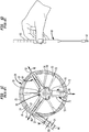
- an exemplary conventional holder 10 for a prosthetic heart valve 20 has a substantially cylindrical hub 30, a commissure support 40 extending downward from the bottom 32 of the hub, and a plurality of legs 50 extending from the outer circumferential surface 34 of the hub.
- the holder 10 has a longitudinal axis A1 that extends in a longitudinal direction L1 of the hub 30.
- the legs 50 extend from the hub 30 at an angle that is radially outward and downward relative to the longitudinal direction L1 of the hub.
- the holder 10 may be made of a rigid plastic material such as ultem or polysulfone, for example.
- a handle 60 configured to be grasped by a user at a grasping portion 61 may be coupled to the top 31 of the hub 30 so that a user may rotate and translate the holder 10.
- a suture 70 (described further below) may temporarily fasten the prosthetic heart valve 20 to the holder 10 while the prosthetic heart valve is manipulated and deployed into a patient.
- the prosthetic heart valve 20 has a rigid frame (e.g., made of titanium; not shown) encapsulated by a cover 22 made, for example, from polyester fabric.
- a cuff 23 at an inflow end of the cover 22 may encapsulate a flexible ring (e.g., made of silicone; not shown) extending circumferentially about the exterior of the rigid frame in a closed curve shape ( e.g., a circle).
- the prosthetic heart valve 20 has three leaflets 24 (e.g., made of bovine pericardial tissue) that coapt together in a central area of the prosthetic heart valve. The leaflets 24 are attached to the frame via stitching between the leaflets and the cover 22.
- the cuff 23 may have a width W1 between an inner edge 27 and an outer edge 28 of the cuff in radial directions perpendicular to the longitudinal axis A1 of about 2.00 mm to about 2.25 mm.
- the diameter of the flow opening through the prosthetic heart valve 20 with the leaflets 24 in an open position is about 19 mm, although in other embodiments, other diameters may be used.
- valve 20 could be used to replace a different native valve, such as the pulmonary/tricuspid valve, or a typically bicuspid valve, such as the mitral valve.
- a bicuspid valve design the prosthetic heart valve 20 may have two leaflets 24.
- the prosthetic heart valve 20 is designed to replace a native valve of a patient, such as the pulmonary, mitral, tricuspid, or aortic valve.
- the prosthetic heart valve 20 may be inserted into a patient whose heart has been stopped, via a thoractomy or open-heart surgery, for example.
- the prosthetic heart valve 20, for example can be configured to be sewn into the native aortic annulus of the patient after removal of the native aortic valve leaflets, with the cuff 23 preferably disposed in a supra-annular position in the ascending aorta above the left ventricle, adjacent the native aortic annulus of the patient.
- the user may position the prosthetic heart valve 20 with the cuff 23 adjacent the native aortic annulus of the patient, and suturing may be applied to stitch the cuff to the native aortic annulus.
- the user may place the suturing circumferentially about the cuff 23 between the cuff and the native aortic annulus, using a single continuous suture or a plurality of interrupted sutures. For example, three sutures may be used, each of the three sutures extending around part of the circumference of the cuff 23.
- the hub 30 has a substantially cylindrical shape that extends along the longitudinal axis A1 from the top 31 to the bottom 32.
- the outer circumferential surface 34 extends circumferentially about the longitudinal axis A1 between the top 31 and the bottom 32.
- the top 31 of the hub 30 has a threaded central opening 36 that is configured to receive a threaded end 62 of the handle 60.
- the commissure support 40 has a trunk 42 extending along the longitudinal axis A1 and three arms 44 extending away from the trunk in respective radial directions R1, R2, R3 that are evenly circumferentially spaced about the trunk at about 120° intervals.
- Each arm 44 has a support surface 46 extending in a plane substantially parallel to the longitudinal direction L1 and substantially perpendicular to the radial direction along which the respective arm extends.
- Each of the support surfaces 46 is configured to support a respective one of the commissures 26 of the prosthetic heart valve 20.
- Each support surface 46 is configured to prevent inward deflection of the respective commissure towards the longitudinal axis A1 due to unintentional contact with the user or a portion of the anatomy of a patient during manipulation and insertion of the prosthetic heart valve into the patient.
- Each of the plurality of legs 50 has an upper end 51 that extends away from the outer circumferential surface 34 of the hub 30 in respective radial directions R4, R5, R6 that are evenly circumferentially spaced about the hub at about 120° intervals.
- Each leg 50 is circumferentially located substantially at the midpoint between two adjacent arms 44 about the longitudinal axis A1, so that each leg is located about 60° away from each of the adjacent arms.
- Each leg 50 has a foot 52 that extends generally parallel to the longitudinal direction L1 and an angled middle section 53 that extends between the upper end 51 and the foot at an angle that is oriented in a direction between the longitudinal direction and the radial directions R4, R5, R6.
- each leg 50 has a suture opening 54 that extends transversely through the leg.
- a bottom 58 of each foot 52 has two suture holes 55 that extend therethrough substantially in the longitudinal direction.
- each foot 52 may have a width W2 between an inner surface 56 and an outer surface 57 of the foot in the respective radial direction R4, R5, R6 of about 1.73 mm.
- the prosthetic heart valve 20 may be engaged with and attached to the holder 10 during transport of the prosthetic heart valve into a patient and during suturing of the prosthetic heart valve into the native aortic annulus of the patient.
- the prosthetic heart valve 20 may be positioned such that the support surfaces 46 of the arms 40 of the holder 10 contact the respective inside surfaces of the commissures 26 of the prosthetic heart valve, such that the legs 50 extend over the outer surfaces of the leaflets 24.
- the feet 52 of the holder 10 may be placed in contact with an upper-facing surface 29 of the cuff 23 of the prosthetic heart valve 20.
- the prosthetic heart valve 20 may be sutured to the holder 10 as shown in FIGS. 1B and 1C .
- the suture 70 may extend down and up each of the legs 50 and across the outer circumferential surface 34 of the hub 30 between the legs. As shown, a single suture 70 is used, but alternatively, a plurality of sutures 70 may together fasten the prosthetic heart valve 20 to the holder 10.
- the suture 70 may extend through a first one of the holes 55, into an interior of the cuff 23 of the prosthetic heart valve 20, out of the cuff and through a second one of the holes.
- the ends of the suture 70 may be tied to one another in a knot 71 ( FIG. 1B ).
- the suture 70 may extend through the suture opening 54 in each of the legs 50 to secure the suture to the upper end 51 of each of the legs.
- the position of the feet 52 on the upward-facing surface 29 of the cuff 23 relative to the inner edge 27 and the outer edge 28 of the cuff defines the clearance C1 and the "cuff bite" B1.
- the width of the upward-facing surface 29 of the cuff 23 between the inner surface 56 of the feet 52 and the inner edge 27 of the cuff in the respective radial direction R4, R5, R6 defines the clearance C1.
- the clearance C1 is the amount of radial width of the cuff 23 at the circumferential locations of the feet 52 between the feet and the leaflets 24.
- An acceptable clearance C1 for preventing the legs 52 from contacting the leaflets 24 when the prosthetic heart valve 20 is sutured to the holder 10 may be about 0.25 mm.
- the width of the upward-facing surface 29 of the cuff 23 between the outer surface 57 of the feet 52 and the outer edge 28 of the cuff in the respective radial direction R4, R5, R6 defines the cuff bite B1.
- the cuff bite B1 is the amount of radial width of the cuff 23 at the circumferential locations of the feet 52 that is available for a suture to "bite" into the cuff during stitching of the cuff to the native annulus of a patient.
- the cuff bite B1 may be calculated by subtracting the width W2 of the feet 52 and the clearance C1 between the feet and the leaflets 24 from the width W1 of the cuff 23.
- the cuff bite B1 may be between about 0.02 mm and about 0.27 mm.
- the values of the cuff bite B1 in any particular example will depend on the width W1 of the particular cuff used and how close the geometric center of the prosthetic heart valve 20 is to the longitudinal axis A1 of the holder 10 after the prosthetic heart valve 20 has been stitched to the holder.
- the width W2 of the feet 52 of the holder 10 may be large enough relative to the width W1 of the cuff 23 so that the cuff bite B1 is too small to permit a user to place stitches into the cuff at the same circumferential locations as the feet. If a user cannot place a stitch into the cuff at the same circumferential location as the feet 52, paravalvular leak may occur around the outside of the cuff at the unstitched locations after implantation of the prosthetic heart valve 20. This situation may be addressed by the holder embodiment shown in FIGS. 2A-2F , which will be described below.
- an exemplary holder 110 for a prosthetic heart valve 120 has a substantially cylindrical hub 130, a commissure support 140 extending downward from the bottom 132 of the hub, and a plurality of legs 150 extending from the outer circumferential surface 134 of the hub.
- the holder 110 has a longitudinal axis A1 that extends in a longitudinal direction L1 of the hub.
- the legs 150 extend from the hub 130 at an angle that is radially outward and downward relative to the longitudinal direction L1 of the hub.
- the holder 110 may be made of a rigid plastic material such as ultem or polysulfone, for example.
- a suture 170 may temporarily fasten the prosthetic heart valve 120 to the holder 110 while the prosthetic heart valve is manipulated and deployed into a patient.
- the prosthetic heart valve 120 has the same features and intended use described above with respect to the prosthetic heart valve 20, except that in the example shown in FIGS. 2D and 2E , the diameter of the flow opening through the prosthetic heat valve 120 with the leaflets 124 in the open position is about 17 mm (in other embodiments, other diameters may be used).
- the cuff 123 may have a width W1 between an inner edge 127 and an outer edge 128 of the cuff in radial directions perpendicular to the longitudinal axis A1 of about 2.00 mm to about 2.25 mm.
- the hub 130 has a substantially cylindrical shape that extends along the longitudinal axis A1 from the top 131 to the bottom 132.
- the outer circumferential surface 134 extends circumferentially about the longitudinal axis A1 between the top 131 and the bottom 132.
- the top 131 of the hub 130 has a threaded central opening 136 that is configured to receive the threaded end 62 of the handle 60.
- the commissure support 140 has a trunk 142 extending along the longitudinal axis A1 and three arms 144 extending away from the trunk in respective radial directions R1, R2, R3 that are evenly circumferentially spaced about the trunk at about 120° intervals.
- Each arm 144 defines a support surface 146 extending in a plane substantially parallel to the longitudinal direction L1 and substantially perpendicular to the radial direction along which the respective arm extends.
- Each of the support surfaces 146 is configured to support a respective one of the commissures 126 of the prosthetic heart valve 120.
- Each support surface 146 is configured to prevent inward deflection of the respective commissure towards the longitudinal axis A1 due to unintentional contact with the user or a portion of the anatomy of a patient during manipulation and insertion of the prosthetic heart valve into the patient.
- Each of the plurality of legs 150 has an upper end 151 that extends away from the outer circumferential surface 134 of the hub 130 in respective radial directions R4, R5, R6 that are evenly circumferentially spaced about the hub at about 120° intervals.
- Each leg 150 is circumferentially located substantially at the midpoint between two adjacent arms 144 about the longitudinal axis A1, so that each leg is located about 60° away from each of the adjacent arms.
- Each leg 150 has a foot 152 that extends generally parallel to the longitudinal direction L1 and an angled middle section 153 that extends between the upper end 151 and the foot at an angle that is oriented in a direction between the longitudinal direction and the radial directions R4, R5, R6.
- Each leg 150 has two suture openings 154a and 154b that extend transversely through the leg.
- Each suture opening 154a extends through the upper end 151 of the respective leg 150, and each suture opening 154b extends through the angled middle section 153 of the respective leg.
- each leg 150 has two suture holes 155 that extend therethrough substantially in the respective radial direction R4, R5, or R6 at a position spaced apart from a bottom 158 of the respective foot.
- each foot 152 may have a width W3 between an inner surface 156 and an outer surface 157 of the foot in the respective radial direction R4, R5, R6 of about 0.66 mm.
- Each suture hole 155 is located within a respective channel 180 that extends substantially in the longitudinal direction L1 on the outer surface 157 of each foot 152.
- Each suture hole 155 is located at a top end 181 of the respective channel 180, and each channel extends to an open bottom end 182 located at the bottom 158 of the respective foot 152.
- each channel 180 has a concave semi-circular cross-section ( FIG. 2C ), although other cross-sectional shapes may be used.
- Each channel has a chamfer 183 to provide an angled transition surface between the inner surface 184 of each suture hole 155 and the concave inner surface 185 of the respective channel 180.
- the inner surface 185 of each channel 180 extends substantially in the longitudinal direction L1, at an angle 190 relative to the bottom 158 of the respective foot 152. In the example shown in FIG. 2F , the angle 190 is about 90°.
- the bottom of the longitudinal centerline 191 of the inner surface 185 of each channel 180 is spaced apart from the inner surface 156 of the respective foot 152 by a distance D3.
- Each foot 152 has a generally rectangular shape when viewed in the respective radial direction R4, R5, R6 ( FIG. 2B ).
- Each channel 180 is spaced apart from a lateral surface 159 of the respective foot 152.
- Each lateral surface 159 intersects the bottom 158 of the foot at a corner 186, which may be chamfered.
- the inner surface 184 of each suture hole 155 is located at a distance D1 from the corner 186 of the closest lateral surface 159, and at a distance D2 from the bottom 158 of the foot 152, the distance D1 being greater than the distance D2.
- the distance D1 preferably is at least 10% greater than the distance D2 so as to prevent the suture 170 from sliding around the closest corner 186 if the suture slips out of its channel 180 due to compression of the cuff 123 and/or stretching of the suture 170.
- the prosthetic heart valve 120 may be engaged with and attached to the holder 110 in the same manner described above with respect to the prosthetic heart valve 20, except that in the example shown in FIGS. 2D and 2E , portions of the suture 170 extend circumferentially through the suture holes 155 of the holder and portions of the suture may extend through both of the suture openings 154a, 154b in each of the legs 150 to prevent incidental contact between the suture and the leaflets 124.
- the position of the feet 152 on the upward-facing surface 129 of the cuff 123 relative to the inner edge 127 and the outer edge 128 of the cuff defines the clearance C2 and the cuff bite B2.
- the width of the upward-facing surface 129 of the cuff 123 between the inner surface 156 of the feet 152 and the inner edge 127 of the cuff in the respective radial direction R4, R5, R6 defines the clearance C2.
- An acceptable clearance C2 for preventing the legs 152 from contacting the leaflets 124 when the prosthetic heart valve 120 is sutured to the holder 110 may be about 0.25 mm.
- the width of the upward-facing surface 129 of the cuff 123 between the outer surface 157 of the feet 152 and the outer edge 128 of the cuff in the respective radial direction R4, R5, R6 defines the cuff bite B2.
- the cuff bite B2 may be calculated by subtracting the width W3 of the feet 152 and the clearance C2 between the feet and the leaflets 124 from the width W1 of the cuff 123.
- the cuff bite B2 may be between about 1.09 mm and about 1.34 mm.
- the cuff bite B2 may be at least two-fifths of the width W1 of the cuff.
- the cuff bite B2 may be at least half of the width W1 of the cuff.
- the values of the cuff bite B2 in any particular example will depend on the width W1 of the particular cuff used and how close the geometric center of the prosthetic heart valve 120 is to the longitudinal axis A1 of the holder 110 after the prosthetic heart valve has been stitched to the holder.
- the larger cuff bite B2 of the embodiment of FIGS. 2D and 2E may have advantages compared to the smaller cuff bite B1 of the embodiment of FIGS. 1B and 1C .
- the larger cuff bite B2 may permit a user to place stitches into the cuff 123 at the same circumferential locations as the feet 152 when the holder 110 is used to position the prosthetic heart valve 120 adjacent the native aortic annulus of a patient for stitching thereto.
- the presence of the channels 180 may provide additional space for a user to place stitches into the cuff 123 at the same circumferential locations as the feet 152 when the holder 110 is used to position the prosthetic heart valve 120 adjacent the native aortic annulus of a patient for stitching thereto.
- These additional stitched locations enabled by the holder 110 may help prevent or lessen paravalvular leak around the outside of the cuff after implantation of the prosthetic heart valve 120.
- the holder 110 When the holder 110 is used to position the prosthetic heart valve 120 adjacent the native aortic annulus of a patient for stitching thereto, and a user places stitches into the cuff 123 at the same circumferential locations as the feet 152, a possibility may arise that the user may inadvertently capture one or more portions of the suture 170 and fasten it to the native annulus of the patient. In such a circumstance, it may be more difficult to remove the holder 110 after the prosthetic heart valve 120 has been stitched into the native annulus of the patient since the suture 170 has been captured. This potential circumstance may be addressed by the variant of the holder feet shown in FIG. 3 , which will be described below.
- each channel 280 of a foot 252 may have a concave semi-circular cross-section extending inward from the outer surface 257 of the foot, in a manner similar to that shown in FIG. 2C , although other cross-sectional shapes may be used.
- Each channel 280 has a chamfer 283 to provide an angled transition surface between the inner surface 284 of each suture hole 255 and the inner surface 285 of the channel 280 that is medially angled with respect to the longitudinal axis A1.
- the inner surface 285 of the respective channel 280 extends at an angle 290 relative to the bottom 258 of the foot 252 and at an angle 292 relative to the longitudinal direction L1.
- FIG. 1 In the example shown in FIG.
- the angle 290 is about 80°, although other angles may be used, such as about 60°, 65°, 70°, 75°, or 85°, for example.
- the bottom of the longitudinal centerline 291 of the inner surface 285 of each channel 280 is spaced apart from the inner surface 256 of the foot 252 by a distance D4 that is less than the distance D3 shown in FIG. 2F .
- the inner surface 285 of each channel extends substantially in the longitudinal direction L1 adjacent the chamfer 283, and then extends at the angle 290 at a starting point 293 spaced apart from the chamfer.
- the inner surface 285 may extend at the angle 290 from a location adjacent the chamfer 283 all the way down to the bottom 258 of the foot 252, or the inner surface may extend substantially in the longitudinal direction L1 for any distance between the chamfer and the bottom of the foot before changing direction to the angle 290. It will be appreciated that ordinarily, the longer that the inner surface 285 extends in the longitudinal direction, the larger that the angle 290 will be so that the bottom 258 of the foot 252 can reach the distance D4.
- the angle 290 may be constant, as shown in FIG. 3 , or it may change along the path from the chamfer 283 to the bottom 258 of the foot 252.
- the angle 290 may begin at about 80° adjacent the chamfer 283, and may gradually increase so that it reaches about 90° at the bottom 258 of the foot 252.
- the angle 290 may begin at about 90° adjacent the chamfer 283, and may gradually decrease so that it reaches about 80° at the bottom 258 of the foot 252.
- the smaller distance D4 between the bottom of the longitudinal centerline 291 of the inner surface 285 of each channel 280 and the inner surface 256 of the foot 252 may have advantages compared to the larger distance D3 of the embodiment of FIGS. 2A-2F .
- a suture similar to the suture 170 may be placed closer to the inner surface 256 and farther away from the outer surface 257 of each foot 252, making it less likely that a user placing stitches close to the outer surface of each foot will inadvertently capture one or more portions of the suture and fasten it to the native annulus of the patient when implanting the prosthetic heart valve.
- the disclosure herein describes multiple embodiments of a holder for a prosthetic heart valve.
- the holder may include a hub having an outer surface extending about a longitudinal axis, a commissure support extending downward from the hub, and a plurality of legs extending outward from the hub in first radial directions.
- Each leg may have a foot extending in a longitudinal direction generally parallel to the longitudinal axis.
- Each foot may have an inner surface, an outer surface, and a bottom, a structure defining two channels on the outer surface of the foot, and defining two suture holes each spaced apart from the bottom of the foot and extending between the inner surface and the outer surface of the foot.
- Each channel may extend from a closed end at a spaced distance from the bottom of the foot to an open end at the bottom of the foot.
- Each channel may define a concave inner surface; and/or each channel may define a chamfer with an angled transition surface extending between an inner surface of a respective one of the suture holes and the concave inner surface of the channel; and/or the concave inner surface of each channel may extend substantially parallel to the longitudinal axis; and/or the concave inner surface of each channel may extend in a medially angled direction, such that a longitudinal centerline of the concave inner surface at the open end of the channel is closer to the inner surface of the foot than the longitudinal centerline of the concave inner surface at the closed end of the channel; and/or each foot may have first and second lateral surfaces that each intersect the bottom of the foot at a corner, and an inner surface of each of the suture holes may be located a first distance from a closest one of the corners and a second distance from the bottom of the foot, the first distance
- the prosthetic heart valve may have a frame extending circumferentially about a longitudinal axis and surrounding a central opening, a plurality of valve leaflets disposed in the central opening and affixed to the frame, adjacent lateral ends of the leaflets each defining a commissure, and a cuff affixed to the frame and extending circumferentially about an exterior of the frame.
- the holder may have a hub, a commissure support extending downward from the hub and having a plurality of support surfaces each in contact with a respective one of the commissures, and a plurality of legs extending outward from the hub in first radial directions. Each leg may have a foot in contact with an upward-facing surface of the cuff.
- Each foot may have an inner surface, an outer surface, and a bottom, a structure defining two channels on the outer surface of the foot, and defining two suture holes each spaced apart from the bottom of the foot and extending between the inner surface and the outer surface of the foot.
- Each channel may extend from a closed end at a spaced distance from the bottom of the foot to an open end at the bottom of the foot.
- Each channel may define a concave inner surface.
- the prosthetic heart valve may be sutured to the holder by at least one suture extending through the suture holes and the cuff at locations adjacent the legs of the holder; and/or the cuff may be made from a fabric material and encapsulates a flexible ring extending circumferentially through the cuff; and/or the cuff may have a first width between an inner edge and an outer edge thereof, and each foot may have a second width between its inner surface and its outer surface, the first width being at least two times the second width; and/or the assembly may define a clearance between the inner edge of the cuff and the inner surface of each foot, and a cuff bite between the outer edge of the cuff and the outer surface of each foot, the cuff bite being at least half of the first width of the cuff; and/or the prosthetic heart valve may be sutured to the holder by one or more sutures, each of the sutures extending around at least a part of a circumference of the cuff, the sutures together
Applications Claiming Priority (1)
| Application Number | Priority Date | Filing Date | Title |
|---|---|---|---|
| US201862664401P | 2018-04-30 | 2018-04-30 |
Publications (2)
| Publication Number | Publication Date |
|---|---|
| EP3563799A1 true EP3563799A1 (fr) | 2019-11-06 |
| EP3563799B1 EP3563799B1 (fr) | 2023-01-11 |
Family
ID=66349401
Family Applications (1)
| Application Number | Title | Priority Date | Filing Date |
|---|---|---|---|
| EP19172035.8A Active EP3563799B1 (fr) | 2018-04-30 | 2019-04-30 | Support de valvule cardiaque |
Country Status (2)
| Country | Link |
|---|---|
| US (1) | US11026787B2 (fr) |
| EP (1) | EP3563799B1 (fr) |
Cited By (5)
| Publication number | Priority date | Publication date | Assignee | Title |
|---|---|---|---|---|
| US11737872B2 (en) | 2018-11-08 | 2023-08-29 | Neovasc Tiara Inc. | Ventricular deployment of a transcatheter mitral valve prosthesis |
| US11779742B2 (en) | 2019-05-20 | 2023-10-10 | Neovasc Tiara Inc. | Introducer with hemostasis mechanism |
| US11793640B2 (en) | 2017-08-25 | 2023-10-24 | Neovasc Tiara Inc. | Sequentially deployed transcatheter mitral valve prosthesis |
| US11872129B2 (en) | 2021-10-07 | 2024-01-16 | Jilin Venus Haoyue Medtech Limited | System and method for holding and delivering a surgical heart valve |
| US11931254B2 (en) | 2019-06-20 | 2024-03-19 | Neovasc Tiara Inc. | Low profile prosthetic mitral valve |
Families Citing this family (1)
| Publication number | Priority date | Publication date | Assignee | Title |
|---|---|---|---|---|
| US11701214B2 (en) * | 2020-05-22 | 2023-07-18 | Cephea Valve Technologies, Inc. | Prosthetic heart valve packaging and attachment assembly |
Citations (3)
| Publication number | Priority date | Publication date | Assignee | Title |
|---|---|---|---|---|
| US20040225356A1 (en) * | 2003-05-09 | 2004-11-11 | Frater Robert W. | Flexible heart valve |
| US20090076599A1 (en) * | 2007-09-17 | 2009-03-19 | Medtronics, Inc. | Heart valve holder assembly for use in valve implantation procedures |
| US9333076B1 (en) * | 2007-05-24 | 2016-05-10 | St. Jude Medical, Inc. | Prosthetic heart valve holder apparatus |
Family Cites Families (4)
| Publication number | Priority date | Publication date | Assignee | Title |
|---|---|---|---|---|
| US8057538B2 (en) * | 2005-02-18 | 2011-11-15 | Medtronic, Inc. | Valve holder |
| EP2331015A1 (fr) * | 2008-09-12 | 2011-06-15 | ValveXchange Inc. | Ensemble valvule avec élément valvule échangeable et jeu d'instruments destiné à changer l'élément valvule |
| US9414913B2 (en) * | 2013-10-25 | 2016-08-16 | Medtronic, Inc. | Stented prosthetic heart valve |
| US9585752B2 (en) * | 2014-04-30 | 2017-03-07 | Edwards Lifesciences Corporation | Holder and deployment system for surgical heart valves |
-
2019
- 2019-04-29 US US16/397,376 patent/US11026787B2/en active Active
- 2019-04-30 EP EP19172035.8A patent/EP3563799B1/fr active Active
Patent Citations (3)
| Publication number | Priority date | Publication date | Assignee | Title |
|---|---|---|---|---|
| US20040225356A1 (en) * | 2003-05-09 | 2004-11-11 | Frater Robert W. | Flexible heart valve |
| US9333076B1 (en) * | 2007-05-24 | 2016-05-10 | St. Jude Medical, Inc. | Prosthetic heart valve holder apparatus |
| US20090076599A1 (en) * | 2007-09-17 | 2009-03-19 | Medtronics, Inc. | Heart valve holder assembly for use in valve implantation procedures |
Cited By (5)
| Publication number | Priority date | Publication date | Assignee | Title |
|---|---|---|---|---|
| US11793640B2 (en) | 2017-08-25 | 2023-10-24 | Neovasc Tiara Inc. | Sequentially deployed transcatheter mitral valve prosthesis |
| US11737872B2 (en) | 2018-11-08 | 2023-08-29 | Neovasc Tiara Inc. | Ventricular deployment of a transcatheter mitral valve prosthesis |
| US11779742B2 (en) | 2019-05-20 | 2023-10-10 | Neovasc Tiara Inc. | Introducer with hemostasis mechanism |
| US11931254B2 (en) | 2019-06-20 | 2024-03-19 | Neovasc Tiara Inc. | Low profile prosthetic mitral valve |
| US11872129B2 (en) | 2021-10-07 | 2024-01-16 | Jilin Venus Haoyue Medtech Limited | System and method for holding and delivering a surgical heart valve |
Also Published As
| Publication number | Publication date |
|---|---|
| US11026787B2 (en) | 2021-06-08 |
| US20190328520A1 (en) | 2019-10-31 |
| EP3563799B1 (fr) | 2023-01-11 |
Similar Documents
| Publication | Publication Date | Title |
|---|---|---|
| EP3563799B1 (fr) | Support de valvule cardiaque | |
| US11179237B2 (en) | Valvular sleeve for valvular prostheses and corresponding device | |
| US20220054257A1 (en) | Two-part mitral valve and implant method | |
| US6126007A (en) | Tissue valve holder | |
| CN107530159B (zh) | 用于心脏治疗的装置、系统和方法 | |
| US10321993B2 (en) | Self-expanding heart valves for coronary perfusion and sealing | |
| US6468305B1 (en) | Two piece valve | |
| US20190314151A1 (en) | Valve replacement devices, delivery device for a valve replacement device and method of production of a valve replacement device | |
| US8869982B2 (en) | Prosthetic heart valve packaging and deployment system | |
| JP3701198B2 (ja) | 環状癒合を高めた縫合リング | |
| US8273118B2 (en) | Heart valve holder assembly for use in valve implantation procedures | |
| US20140358224A1 (en) | Six cell inner stent device for prosthetic mitral valves | |
| US20150005874A1 (en) | Atrial Thrombogenic Sealing Pockets for Prosthetic Mitral Valves | |
| US20140379076A1 (en) | Halo Wire Fluid Seal Device for Prosthetic Mitral Valves | |
| US20140316516A1 (en) | Multi-component cuff designs for transcatheter mitral valve replacement subvalvular sealing apparatus for transcatheter mitral valves and wire framed leaflet assembly | |
| US20060095125A1 (en) | Attachment of a sewing cuff to a heart valve | |
| US20130184814A1 (en) | Methods of implant of a heart valve with a convertible sewing ring | |
| US20120179244A1 (en) | Device and System for Transcatheter Mitral Valve Replacement | |
| CA2664223A1 (fr) | Attachement de valvule cardiaque sans suture | |
| JP2016504154A (ja) | 外科用心臓弁の柔軟ステントフレーム補剛材 | |
| US9480563B2 (en) | Valve holder with leaflet protection | |
| AU2019253795B2 (en) | Device and system for transcatheter mitral valve replacement | |
| WO2019128583A1 (fr) | Prothèse de valvule cardiaque et stent associé | |
| US20070168022A1 (en) | Heart valve | |
| WO2001012105A1 (fr) | Anneau de suture a tissu autologue utilise pour l'implantation de valvule cardiaque |
Legal Events
| Date | Code | Title | Description |
|---|---|---|---|
| PUAI | Public reference made under article 153(3) epc to a published international application that has entered the european phase |
Free format text: ORIGINAL CODE: 0009012 |
|
| STAA | Information on the status of an ep patent application or granted ep patent |
Free format text: STATUS: THE APPLICATION HAS BEEN PUBLISHED |
|
| AK | Designated contracting states |
Kind code of ref document: A1 Designated state(s): AL AT BE BG CH CY CZ DE DK EE ES FI FR GB GR HR HU IE IS IT LI LT LU LV MC MK MT NL NO PL PT RO RS SE SI SK SM TR |
|
| AX | Request for extension of the european patent |
Extension state: BA ME |
|
| STAA | Information on the status of an ep patent application or granted ep patent |
Free format text: STATUS: REQUEST FOR EXAMINATION WAS MADE |
|
| 17P | Request for examination filed |
Effective date: 20200506 |
|
| STAA | Information on the status of an ep patent application or granted ep patent |
Free format text: STATUS: EXAMINATION IS IN PROGRESS |
|
| 17Q | First examination report despatched |
Effective date: 20200812 |
|
| STAA | Information on the status of an ep patent application or granted ep patent |
Free format text: STATUS: EXAMINATION IS IN PROGRESS |
|
| GRAP | Despatch of communication of intention to grant a patent |
Free format text: ORIGINAL CODE: EPIDOSNIGR1 |
|
| STAA | Information on the status of an ep patent application or granted ep patent |
Free format text: STATUS: GRANT OF PATENT IS INTENDED |
|
| INTG | Intention to grant announced |
Effective date: 20220923 |
|
| GRAS | Grant fee paid |
Free format text: ORIGINAL CODE: EPIDOSNIGR3 |
|
| GRAA | (expected) grant |
Free format text: ORIGINAL CODE: 0009210 |
|
| STAA | Information on the status of an ep patent application or granted ep patent |
Free format text: STATUS: THE PATENT HAS BEEN GRANTED |
|
| AK | Designated contracting states |
Kind code of ref document: B1 Designated state(s): AL AT BE BG CH CY CZ DE DK EE ES FI FR GB GR HR HU IE IS IT LI LT LU LV MC MK MT NL NO PL PT RO RS SE SI SK SM TR |
|
| REG | Reference to a national code |
Ref country code: GB Ref legal event code: FG4D |
|
| REG | Reference to a national code |
Ref country code: CH Ref legal event code: EP |
|
| REG | Reference to a national code |
Ref country code: DE Ref legal event code: R096 Ref document number: 602019024189 Country of ref document: DE |
|
| REG | Reference to a national code |
Ref country code: IE Ref legal event code: FG4D |
|
| REG | Reference to a national code |
Ref country code: AT Ref legal event code: REF Ref document number: 1542959 Country of ref document: AT Kind code of ref document: T Effective date: 20230215 |
|
| REG | Reference to a national code |
Ref country code: LT Ref legal event code: MG9D |
|
| REG | Reference to a national code |
Ref country code: NL Ref legal event code: MP Effective date: 20230111 |
|
| PGFP | Annual fee paid to national office [announced via postgrant information from national office to epo] |
Ref country code: GB Payment date: 20230315 Year of fee payment: 5 |
|
| REG | Reference to a national code |
Ref country code: AT Ref legal event code: MK05 Ref document number: 1542959 Country of ref document: AT Kind code of ref document: T Effective date: 20230111 |
|
| PG25 | Lapsed in a contracting state [announced via postgrant information from national office to epo] |
Ref country code: NL Free format text: LAPSE BECAUSE OF FAILURE TO SUBMIT A TRANSLATION OF THE DESCRIPTION OR TO PAY THE FEE WITHIN THE PRESCRIBED TIME-LIMIT Effective date: 20230111 |
|
| P01 | Opt-out of the competence of the unified patent court (upc) registered |
Effective date: 20230616 |
|
| PG25 | Lapsed in a contracting state [announced via postgrant information from national office to epo] |
Ref country code: RS Free format text: LAPSE BECAUSE OF FAILURE TO SUBMIT A TRANSLATION OF THE DESCRIPTION OR TO PAY THE FEE WITHIN THE PRESCRIBED TIME-LIMIT Effective date: 20230111 Ref country code: PT Free format text: LAPSE BECAUSE OF FAILURE TO SUBMIT A TRANSLATION OF THE DESCRIPTION OR TO PAY THE FEE WITHIN THE PRESCRIBED TIME-LIMIT Effective date: 20230511 Ref country code: NO Free format text: LAPSE BECAUSE OF FAILURE TO SUBMIT A TRANSLATION OF THE DESCRIPTION OR TO PAY THE FEE WITHIN THE PRESCRIBED TIME-LIMIT Effective date: 20230411 Ref country code: LV Free format text: LAPSE BECAUSE OF FAILURE TO SUBMIT A TRANSLATION OF THE DESCRIPTION OR TO PAY THE FEE WITHIN THE PRESCRIBED TIME-LIMIT Effective date: 20230111 Ref country code: LT Free format text: LAPSE BECAUSE OF FAILURE TO SUBMIT A TRANSLATION OF THE DESCRIPTION OR TO PAY THE FEE WITHIN THE PRESCRIBED TIME-LIMIT Effective date: 20230111 Ref country code: HR Free format text: LAPSE BECAUSE OF FAILURE TO SUBMIT A TRANSLATION OF THE DESCRIPTION OR TO PAY THE FEE WITHIN THE PRESCRIBED TIME-LIMIT Effective date: 20230111 Ref country code: ES Free format text: LAPSE BECAUSE OF FAILURE TO SUBMIT A TRANSLATION OF THE DESCRIPTION OR TO PAY THE FEE WITHIN THE PRESCRIBED TIME-LIMIT Effective date: 20230111 Ref country code: AT Free format text: LAPSE BECAUSE OF FAILURE TO SUBMIT A TRANSLATION OF THE DESCRIPTION OR TO PAY THE FEE WITHIN THE PRESCRIBED TIME-LIMIT Effective date: 20230111 |
|
| PGFP | Annual fee paid to national office [announced via postgrant information from national office to epo] |
Ref country code: DE Payment date: 20230320 Year of fee payment: 5 |
|
| PG25 | Lapsed in a contracting state [announced via postgrant information from national office to epo] |
Ref country code: SE Free format text: LAPSE BECAUSE OF FAILURE TO SUBMIT A TRANSLATION OF THE DESCRIPTION OR TO PAY THE FEE WITHIN THE PRESCRIBED TIME-LIMIT Effective date: 20230111 Ref country code: PL Free format text: LAPSE BECAUSE OF FAILURE TO SUBMIT A TRANSLATION OF THE DESCRIPTION OR TO PAY THE FEE WITHIN THE PRESCRIBED TIME-LIMIT Effective date: 20230111 Ref country code: IS Free format text: LAPSE BECAUSE OF FAILURE TO SUBMIT A TRANSLATION OF THE DESCRIPTION OR TO PAY THE FEE WITHIN THE PRESCRIBED TIME-LIMIT Effective date: 20230511 Ref country code: GR Free format text: LAPSE BECAUSE OF FAILURE TO SUBMIT A TRANSLATION OF THE DESCRIPTION OR TO PAY THE FEE WITHIN THE PRESCRIBED TIME-LIMIT Effective date: 20230412 Ref country code: FI Free format text: LAPSE BECAUSE OF FAILURE TO SUBMIT A TRANSLATION OF THE DESCRIPTION OR TO PAY THE FEE WITHIN THE PRESCRIBED TIME-LIMIT Effective date: 20230111 |
|
| REG | Reference to a national code |
Ref country code: DE Ref legal event code: R097 Ref document number: 602019024189 Country of ref document: DE |
|
| PG25 | Lapsed in a contracting state [announced via postgrant information from national office to epo] |
Ref country code: SM Free format text: LAPSE BECAUSE OF FAILURE TO SUBMIT A TRANSLATION OF THE DESCRIPTION OR TO PAY THE FEE WITHIN THE PRESCRIBED TIME-LIMIT Effective date: 20230111 Ref country code: RO Free format text: LAPSE BECAUSE OF FAILURE TO SUBMIT A TRANSLATION OF THE DESCRIPTION OR TO PAY THE FEE WITHIN THE PRESCRIBED TIME-LIMIT Effective date: 20230111 Ref country code: EE Free format text: LAPSE BECAUSE OF FAILURE TO SUBMIT A TRANSLATION OF THE DESCRIPTION OR TO PAY THE FEE WITHIN THE PRESCRIBED TIME-LIMIT Effective date: 20230111 Ref country code: DK Free format text: LAPSE BECAUSE OF FAILURE TO SUBMIT A TRANSLATION OF THE DESCRIPTION OR TO PAY THE FEE WITHIN THE PRESCRIBED TIME-LIMIT Effective date: 20230111 Ref country code: CZ Free format text: LAPSE BECAUSE OF FAILURE TO SUBMIT A TRANSLATION OF THE DESCRIPTION OR TO PAY THE FEE WITHIN THE PRESCRIBED TIME-LIMIT Effective date: 20230111 |
|
| PLBE | No opposition filed within time limit |
Free format text: ORIGINAL CODE: 0009261 |
|
| STAA | Information on the status of an ep patent application or granted ep patent |
Free format text: STATUS: NO OPPOSITION FILED WITHIN TIME LIMIT |
|
| PG25 | Lapsed in a contracting state [announced via postgrant information from national office to epo] |
Ref country code: SK Free format text: LAPSE BECAUSE OF FAILURE TO SUBMIT A TRANSLATION OF THE DESCRIPTION OR TO PAY THE FEE WITHIN THE PRESCRIBED TIME-LIMIT Effective date: 20230111 |
|
| REG | Reference to a national code |
Ref country code: CH Ref legal event code: PL |
|
| 26N | No opposition filed |
Effective date: 20231012 |
|
| PG25 | Lapsed in a contracting state [announced via postgrant information from national office to epo] |
Ref country code: LU Free format text: LAPSE BECAUSE OF NON-PAYMENT OF DUE FEES Effective date: 20230430 |
|
| REG | Reference to a national code |
Ref country code: BE Ref legal event code: MM Effective date: 20230430 |
|
| PG25 | Lapsed in a contracting state [announced via postgrant information from national office to epo] |
Ref country code: MC Free format text: LAPSE BECAUSE OF FAILURE TO SUBMIT A TRANSLATION OF THE DESCRIPTION OR TO PAY THE FEE WITHIN THE PRESCRIBED TIME-LIMIT Effective date: 20230111 |
|
| PG25 | Lapsed in a contracting state [announced via postgrant information from national office to epo] |
Ref country code: SI Free format text: LAPSE BECAUSE OF FAILURE TO SUBMIT A TRANSLATION OF THE DESCRIPTION OR TO PAY THE FEE WITHIN THE PRESCRIBED TIME-LIMIT Effective date: 20230111 Ref country code: MC Free format text: LAPSE BECAUSE OF FAILURE TO SUBMIT A TRANSLATION OF THE DESCRIPTION OR TO PAY THE FEE WITHIN THE PRESCRIBED TIME-LIMIT Effective date: 20230111 Ref country code: LI Free format text: LAPSE BECAUSE OF NON-PAYMENT OF DUE FEES Effective date: 20230430 Ref country code: FR Free format text: LAPSE BECAUSE OF NON-PAYMENT OF DUE FEES Effective date: 20230430 Ref country code: CH Free format text: LAPSE BECAUSE OF NON-PAYMENT OF DUE FEES Effective date: 20230430 |
|
| REG | Reference to a national code |
Ref country code: IE Ref legal event code: MM4A |
|
| PG25 | Lapsed in a contracting state [announced via postgrant information from national office to epo] |
Ref country code: BE Free format text: LAPSE BECAUSE OF NON-PAYMENT OF DUE FEES Effective date: 20230430 |
|
| PG25 | Lapsed in a contracting state [announced via postgrant information from national office to epo] |
Ref country code: IE Free format text: LAPSE BECAUSE OF NON-PAYMENT OF DUE FEES Effective date: 20230430 |
|
| PG25 | Lapsed in a contracting state [announced via postgrant information from national office to epo] |
Ref country code: IE Free format text: LAPSE BECAUSE OF NON-PAYMENT OF DUE FEES Effective date: 20230430 |
|
| PGFP | Annual fee paid to national office [announced via postgrant information from national office to epo] |
Ref country code: GB Payment date: 20240314 Year of fee payment: 6 |