EP3562068B1 - Lichtquelle für ein quantenkommunikationssystem und codierungsvorrichtung - Google Patents
Lichtquelle für ein quantenkommunikationssystem und codierungsvorrichtung Download PDFInfo
- Publication number
- EP3562068B1 EP3562068B1 EP17886886.5A EP17886886A EP3562068B1 EP 3562068 B1 EP3562068 B1 EP 3562068B1 EP 17886886 A EP17886886 A EP 17886886A EP 3562068 B1 EP3562068 B1 EP 3562068B1
- Authority
- EP
- European Patent Office
- Prior art keywords
- slave
- pulse
- laser
- master
- slave laser
- Prior art date
- Legal status (The legal status is an assumption and is not a legal conclusion. Google has not performed a legal analysis and makes no representation as to the accuracy of the status listed.)
- Active
Links
Images


Classifications
-
- H—ELECTRICITY
- H04—ELECTRIC COMMUNICATION TECHNIQUE
- H04B—TRANSMISSION
- H04B10/00—Transmission systems employing electromagnetic waves other than radio-waves, e.g. infrared, visible or ultraviolet light, or employing corpuscular radiation, e.g. quantum communication
- H04B10/50—Transmitters
- H04B10/508—Pulse generation, e.g. generation of solitons
-
- H—ELECTRICITY
- H04—ELECTRIC COMMUNICATION TECHNIQUE
- H04B—TRANSMISSION
- H04B10/00—Transmission systems employing electromagnetic waves other than radio-waves, e.g. infrared, visible or ultraviolet light, or employing corpuscular radiation, e.g. quantum communication
- H04B10/50—Transmitters
- H04B10/516—Details of coding or modulation
- H04B10/524—Pulse modulation
-
- H—ELECTRICITY
- H04—ELECTRIC COMMUNICATION TECHNIQUE
- H04B—TRANSMISSION
- H04B10/00—Transmission systems employing electromagnetic waves other than radio-waves, e.g. infrared, visible or ultraviolet light, or employing corpuscular radiation, e.g. quantum communication
- H04B10/50—Transmitters
- H04B10/516—Details of coding or modulation
- H04B10/54—Intensity modulation
- H04B10/541—Digital intensity or amplitude modulation
-
- H—ELECTRICITY
- H04—ELECTRIC COMMUNICATION TECHNIQUE
- H04B—TRANSMISSION
- H04B10/00—Transmission systems employing electromagnetic waves other than radio-waves, e.g. infrared, visible or ultraviolet light, or employing corpuscular radiation, e.g. quantum communication
- H04B10/50—Transmitters
- H04B10/516—Details of coding or modulation
- H04B10/548—Phase or frequency modulation
- H04B10/556—Digital modulation, e.g. differential phase shift keying [DPSK] or frequency shift keying [FSK]
- H04B10/5561—Digital phase modulation
-
- H—ELECTRICITY
- H04—ELECTRIC COMMUNICATION TECHNIQUE
- H04B—TRANSMISSION
- H04B10/00—Transmission systems employing electromagnetic waves other than radio-waves, e.g. infrared, visible or ultraviolet light, or employing corpuscular radiation, e.g. quantum communication
- H04B10/70—Photonic quantum communication
-
- H—ELECTRICITY
- H04—ELECTRIC COMMUNICATION TECHNIQUE
- H04L—TRANSMISSION OF DIGITAL INFORMATION, e.g. TELEGRAPHIC COMMUNICATION
- H04L9/00—Cryptographic mechanisms or cryptographic arrangements for secret or secure communications; Network security protocols
- H04L9/001—Cryptographic mechanisms or cryptographic arrangements for secret or secure communications; Network security protocols using chaotic signals
-
- H—ELECTRICITY
- H04—ELECTRIC COMMUNICATION TECHNIQUE
- H04L—TRANSMISSION OF DIGITAL INFORMATION, e.g. TELEGRAPHIC COMMUNICATION
- H04L9/00—Cryptographic mechanisms or cryptographic arrangements for secret or secure communications; Network security protocols
- H04L9/08—Key distribution or management, e.g. generation, sharing or updating, of cryptographic keys or passwords
- H04L9/0816—Key establishment, i.e. cryptographic processes or cryptographic protocols whereby a shared secret becomes available to two or more parties, for subsequent use
- H04L9/0852—Quantum cryptography
-
- H—ELECTRICITY
- H04—ELECTRIC COMMUNICATION TECHNIQUE
- H04L—TRANSMISSION OF DIGITAL INFORMATION, e.g. TELEGRAPHIC COMMUNICATION
- H04L9/00—Cryptographic mechanisms or cryptographic arrangements for secret or secure communications; Network security protocols
- H04L9/08—Key distribution or management, e.g. generation, sharing or updating, of cryptographic keys or passwords
- H04L9/0816—Key establishment, i.e. cryptographic processes or cryptographic protocols whereby a shared secret becomes available to two or more parties, for subsequent use
- H04L9/0852—Quantum cryptography
- H04L9/0858—Details about key distillation or coding, e.g. reconciliation, error correction, privacy amplification, polarisation coding or phase coding
Definitions
- the present disclosure relates to the technical field of quantum secure communication, and in particular to an encoding device and a light source for the encoding device.
- D1 ( CN106209361A ) discloses a star quantum key distribution network without a trusted relay based on a MDIQKD protocol.
- the star quantum key distribution network is expanded to a star network structure based on a point-to-point MDIQKD system.
- network resource consumption is saved and the difficulty due to network expansion can be solved.
- the light source structure, equipment used in a time feedback scheme, a phase feedback scheme and a polarization feedback scheme are simple and reusable. Therefore, the quantum key distribution network is simple, easy to integrate and has a low cost.
- feedback requirements may also be reduced through further optimization, thus laying foundation for safe, high-speed and large-scale quantum secret communication.
- D2 discloses a master laser which outputs a sequence of phase-randomized optical pulses, which serve as pulse injection seeding for a slave laser and cause the slave laser to output a sequence of phase-randomized optical pulses.
- the lasers are preferably gain-switched lasers.
- the jitter of the pulses output by the slave laser is less than the jitter of the pulses output by the master laser.
- the difference in jitter is realized by synchronizing periodic electrical driving signals of the master laser and the slave laser such that light from the master laser is in the cavity of the slave laser before the slave laser gain modulation is raised above a lasing threshold.
- One slave light pulse is generated during each period of time when a master light pulse is received.
- the output from the slave laser is inputted to an interference system, such as an interferometer or beam combiner, which may form part of a random number generator or a quantum key distribution system.
- the communication technology which is essential in modern society, is developing rapidly.
- the quantum secure communication technology is an emerging technology in the field of communication technology and has a significant application prospect.
- the quantum secure communication technology relates to an interdisciplinary field of quantum mechanics, modern communication and modern cryptography, and has an incomparable advantage in safety compared with conventional communication technology.
- the quantum key distribution (QKD) technology is widely used and is fit for commercialization.
- the QKD technology is founded based on the principle of quantum mechanics.
- the BB84 protocol as the first quantum key distribution protocol proposed in 1984 has been widely used. It involves the most mature technology and has the best comprehensive advantage.
- the BB84 protocol uses the four-state encoding method. In the four-state encoding method, information is encoded in a polarization encoding manner or a phase encoding manner, then transmitted, and at last decoded by a simple decoding device including a wave plate, a beam splitter, a phototube, a circuit and the like.
- the BB84 protocol requires a simple structure and system technology, which is easy to maintain and produce in mass. Therefore, the BB84 protocol has an incompatible advantage in key rate and distance compared with other protocols.
- the well-known photon number splitting attack intercepts and attacks the multi-photon component in a non-ideal single photon source, to perform eavesdropping.
- a way to avoid this photon number splitting attack is to adjust intensity of light at a transmitting end based on the decoy-state theory, that is, employing a decoy-state BB84 quantum key distribution system.
- the encoding scheme such as polarization encoding, phase encoding and time-bin-phase encoding are mainly used.
- the polarization encoding has advantages of a low cost and a simple structure, and has disadvantages of susceptibility to fiber polarization disturbance, which directly affects a bit error rate.
- the compensation for polarization thus required may result in a time waste and thus a reduced or unstable key rate.
- the phase encoding scheme adopts light pulses generated by an unbalanced interferometer, and encodes the information on a phase difference between two adjacent light pulses, which is less affected by polarization disturbance of an optical fiber. Therefore, the polarization disturbance will not result in an increase in the bit error rate, and the phase encoding is favorable for application in long-distance transmission or strong external disturbance circumstance.
- the phase encoding has a disadvantage that a receiver of a conventional phase system has a large insertion loss, thus both the key rate and the largest distance are lower than that of the polarization system.
- the time-bin-phase encoding scheme is developed based on the above situation. It is performed under two bases, that is, a time basis (that is, a Z basis with an eigenstate of
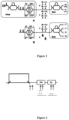
- Figure 1 shows an encoding device for time-bin phase encoding.
- a laser pulse from a light source is inputted to an unbalanced Mach-Zehnder (MZ) interferometer, to form two pulse components temporally separated from each other.
- the two pulse components are inputted to a balanced interferometer one after another.
- the balanced interferometer includes two Phase Modulators (PM), and different interference light intensities and phases could be generated by adjusting a relative phase difference between the two PMs. For pulse components arriving at different times, different light intensities and phases may be obtained by modulating the voltage on PM.
- the encoding device shown in Figure 1 could perform encoding on three bases.
- phase differences 0 and ⁇ of the balanced interferometer respectively correspond to an extinction result and an opposite lighting result in the case of Z basis encoding.
- Phase differences ⁇ /2 and - ⁇ /2 of the balanced interferometer both correspond to a case of outputting pulses, and the phase difference between the pulses determines whether the X basis encoding or the Y basis encoding is performed.
- FIG. 2 shows an encoding device for time-bin phase encoding.
- a laser pulse from a light source is inputted to an unbalanced Mach-Zehnder (MZ) interferometer, to form two pulse components temporally separated from each other.
- MZ Mach-Zehnder
- four phases 0, ⁇ , ⁇ /2 and 3 ⁇ /2 are applied between the two pulse components by the phase modulator.
- the two successive pulse components are modulated by an Intensity Modulator (IM).
- IM Intensity Modulator
- the two pulse components are both passed through the intensity modulator with a half intensity left. Since the intensity modulator may function as a balanced interferometer, the encoding device shown in Figure 1 is consistent with the encoding device shown in Figure 2 in encoding principle.
- the known encoding device for time-bin phase encoding has defects in basis stability, key rate and the stability of the key rate, especially in a poor encoding condition in which frequent intensity feedback is required for stabilizing the time-bin encoding, or phase feedback is required for stabilizing the phase encoding.
- other feedback devices and structures are required, resulting in an increased cost of the system and poor information transmission efficiency, thus the usage range is limited.
- the conventional encoding device for performing both time-bin encoding and phase encoding has deficiency of unstable encoding and poor extinction ratio, which directly results in a low communication transmission efficiency and a limited transmission distance.
- Toshiba Corporation has proposed a solution in which the pulse light source is realized using a pulse injection locking technique in the quantum communication system.
- the light source solution based on the pulse injection locking technique spectrum performance of the light pulse is better, and the interference performance of the encoding state is improved, such that the encoding performance is improved.
- the polarization encoding is performed, which may be affected by change in polarization of a fiber during transmission, and the polarization feedback is required for compensating polarization deviation.
- the light source still outputs a light pulse with a random phase, and the final interference effect is enhanced just by improving the spectrum performance of the light pulse and reducing the time jitter of the light pulse.
- this light source solution only the interference effect of the light pulse is improved to a certain extent, while the above defects in the encoding device for time-bin phase encoding still not be solved, resulting in an insufficient improvement in the performance of the whole communication system.
- a light source for performing both time-bin encoding and phase encoding, and an encoding device using the light source are provided in the present disclosure, to allow time-bin phase encoding with a high stability and a high extinction ratio.
- the invention of the present disclosure therefore concerns a light source for performing both time-bin encoding and phase encoding according to independent claim 1. Further emboiments of the invention are found in the dependent claims.
- the light source includes a master laser and a slave laser.
- the master laser is configured to output, in response to a master drive signal from a master drive signal source, a master laser pulse during a system period, to form a seed light.
- the slave laser is configured to output, under stimulation of the seed light and in response to a slave drive signal from a slave drive signal source, a slave laser pulse in an injection locking manner, to encode a signal light pulse.
- the slave drive signal comprises one of a first slave drive signal, a second slave drive signal and a third slave drive signal.
- One of the first slave drive signal, the second slave drive signal and the third slave drive signal is randomly selected and outputted during a system period, to drive the slave laser.
- the slave laser may be configured to output only one first slave laser pulse in response to the first slave drive signal, where the first slave laser pulse is generated under stimulation of a pulse component of the master laser pulse at a first time position.
- the slave laser may be configured to output only one second slave laser pulse in response to the second slave drive signal, where the second slave laser pulse is generated under stimulation of a pulse component of the master laser pulse at a second time position.
- the slave laser may be configured to output two successive third slave laser pulses in response to the third slave drive signal, where the two third slave laser pulses are generated respectively under stimulation of a pulse component of the master laser pulse at a third time position and a pulse component of the master laser pulse at a fourth time position. Therefore, in a case that the light source in the present disclosure is applied in the Z basis encoding, a high and stable extinction ratio can be achieved, and two successive laser pulses with a stable phase relation are generated for the X basis encoding.
- the master laser is connected to the slave laser via an optical transmission element.
- the master laser pulse is inputted to a first port of the optical transmission element and is outputted from a second port of the optical transmission element, and is injected into the slave laser after being outputted from the second port of the optical transmission element.
- the slave laser pulse is inputted to the second port of the optical transmission element and is outputted from a third port of the optical transmission element.
- the number of each of the master laser and the slave laser is one.
- An unbalanced interferometer is arranged between the master laser and the optical transmission element.
- An arm length difference of the unbalanced interferometer is set to allow a time difference between two successive pulse components formed through splitting the master laser pulse by the unbalanced interferometer is equal to a time interval between the two third slave laser pulses, and the two pulse components have the same wavelength.
- the number of the master laser is one
- the number of the slave laser is two
- the number of the optical transmission element connected to the slave laser is two.
- the master laser is connected to a first beam splitter, which is connected to the two slave lasers respectively via the two optical transmission elements.
- the two slave lasers are connected to a second beam splitter respectively via the two optical transmission elements, to combine the two slave laser pulses outputted from the two slave lasers, and then the combined two slave laser pulses are outputted.
- the first beam splitter is configured to split the master laser pulse into the two pulse components, and the two pulse components have the same wavelength.
- an operating frequency of the master laser is equal to a system frequency.
- An operating frequency of the slave laser is at least twice the operating frequency of the master laser.
- a width of the master laser pulse is greater than a width of the slave laser pulse.
- the two pulse components formed through splitting the master laser pulse by the unbalanced interferometer, when being injected into the slave laser respectively covers the two successive third slave laser pulses in time during the system period.
- an operating frequency of the master laser and an operating frequency of the slave laser are equal to a system frequency.
- the width of the master laser pulse is greater than the width of the slave laser pulse.
- the two pulse components formed through splitting the master laser pulse by the first beam splitter respectively covers one of two third slave laser pulses at different time positions during the system period when being injected into the slave laser.
- a tunable time delay element may be further arranged between the optical transmission element and the second beam splitter.
- the optical transmission element is a circulator or a beam splitter.
- the first time position may be identical to the third time position and the second time position may be identical to the fourth time position.
- an intensity of the first slave laser pulse is equal to an intensity of the second slave laser pulse, and the intensity of the first slave laser pulse is twice an intensity of the third slave laser pulse.
- an encoding device for performing both time-bin encoding and phase encoding is further provided.
- the encoding device may include the light source described above.
- the encoding device may further include at least one of a phase modulator and an intensity modulator.
- the phase modulator is configured to modulate a phase difference between the two successive third slave laser pulses.
- the intensity modulator is configured to modulate a relative intensity among the first slave laser pulse, the second slave laser pulse and the third slave laser pulse.
- the light source provided in the present disclosure has a novel structure suitable for an application in which both time-bin encoding and phase encoding are performed which is formed based on the injection locking technique and the laser internal modulation technique.
- the pulsed light resource may provide a time-bin state (the Z basis) with a high and stable extinction ratio with the laser internal modulation technique.
- the pulsed light resource may provide two pulses with a fixed time relation and a fixed phase relation rather than providing a random pulse with the laser internal modulation technology, for the phase encoding (the X basis). In this way, a preconception that the laser internal modulation technique is not directly used for phase encoding (the X basis) due to that only pulses with a random phase relation are generated with the laser internal modulation technique is eliminated.
- the light source includes a master laser and at least a slave laser.
- the master laser is configured to output a master laser pulse in response to a master drive signal from a master drive signal source, to form a seed light.
- the slave laser is configured to output a slave laser pulse in response to a slave drive signal from a slave drive signal source, to perform encoding.
- the slave drive signal includes one of a first slave drive signal, a second slave drive signal and a third slave drive signal, and the slave drive signal source randomly outputs one of the first slave drive signal, the second slave drive signal and the third slave drive signal.
- the slave laser outputs only one first slave laser pulse in response to the first slave drive signal, and the first slave laser pulse is generated under stimulation of a pulse component of the master laser pulse at a first time position.
- the slave laser outputs only one second slave laser pulse in response to the second slave drive signal, and the second slave laser pulse is generated under stimulation of a pulse component of the master laser pulse at a second time position.
- the slave laser outputs two successive third slave laser pulses in response to the third slave drive signal, and the two successive third slave laser pulses are generated respectively under stimulation of a pulse component of the master laser pulse at a third time position and a pulse component of the master laser pulse at a fourth time position.
- time positions such as the first time position, the second time position, the third time position and the fourth time position may be used to indicate relative time positions during a system period.
- the light source in the present disclosure is suitable for time-bin phase encoding.
- the first slave laser pulse and the second slave laser pulse may be used for Z basis encoding, that is, time-bin encoding.
- the two successive third slave laser pulses may be used for X basis encoding, that is, phase encoding.
- the slave drive signal source may output one of the first slave laser pulse and the second slave laser pulse, to allow the slave laser to output a slave laser pulse with a fixed time feature (for example, temporally preceding or temporally successive) under stimulation of a master laser pulse, to perform time-bin encoding.
- the slave drive signal source may output the third slave drive signal, to allow the slave laser to output two successive third slave laser pulses between with a fixed time relation and a fixed phase relation under stimulation of the master laser pulse, to perform phase encoding.
- the first slave laser pulse and the second slave laser pulse may be set to have the same intensity, and each of the two successive third slave laser pulses may be set to have an intensity of a half of the intensity of the first slave laser pulse or the second slave laser pulse.
- the first time position may be identical to the third time position and the second time position may be identical to the fourth time position.
- the drive signals are not limited to the first slave drive signal, the second slave drive signal and the third slave drive signal, and there may be other slave drive signals. Therefore, under the stimulation of a master laser pulse, the slave laser may not be limited to just outputting the first slave laser pulse, the second slave laser pulse and the third slave laser pulse. Instead, the slave laser may output one slave laser pulse at another time position, or output more successive slave laser pulses with a fixed time relation and a fixed phase relation.
- Figures 3 to 6 show several embodiments of the light source in the present disclosure.
- the drive signal source outputs the first slave drive signal, the second slave drive signal and the third slave drive signal, and the first time position is identical to the third time position and the second time position is identical to the fourth time position is described as an example.
- those skilled in the art should understand that those embodiments are only exemplary, and not intended to limit the present disclosure.
- Figure 3A shows a light source according to a first embodiment of the present disclosure not covered by the scope of the claims.
- the light source includes a master laser 11 and a slave laser 12.
- the master laser 11 is connected to the slave laser 12 via an optical transmission element 13.
- the optical transmission element 13 may include three ports, that is, a port 1 to a port3. Light inputted to the port 1 may be outputted from the port 2, and light inputted to the port 2 may be outputted from the port 3.
- the master laser 11 is connected to the port 1 of the optical transmission element 13.
- the slave laser 12 is connected to the port 2 of the optical transmission element 13.
- the port 3 of the optical transmission element 13 severs as an output port of the light source.
- the optical transmission element may be a circulator or a beam splitter.
- the circulator is used as the optical transmission element.
- An operating frequency of the master laser 11 may be equal to the system frequency.
- An operating frequency of the slave laser 12 may be at least twice the operating frequency of the master laser 11.
- a total width (that is, a sum of pulse widths and a time interval) of two successive slave laser pulses is less than a width of a master laser pulse, such that the two slave laser pulses are generated under stimulation of the master laser pulse, as shown in Figure 3B .
- the master laser 11 outputs the master laser pulse.
- the master laser pulse is directly injected into the slave laser 12 via the port 2 of the circulator 13 as a seed light.
- the slave laser 12 By adjusting a relative time delay between the master laser and the slave laser, to allow the master laser pulse injected into the slave laser to cover two successive slave laser pulses in time during a system period, the slave laser 12 generates two successive slave laser pulses in an injection locking manner under the stimulation of the master laser pulse as the seed light.
- the slave laser pulse is outputted from the port 3 of the circulator 13, and serves as an output pulse of the light source.
- a slave drive signal source outputs a third slave drive signal, to allow the slave laser to generate, under stimulation of the master laser pulse injected to the slave laser, two slave laser pulses at the third (or the first) time position and the fourth (or the second) time position in the injection locking manner.
- the two seed lights used to stimulate the slave laser to generate the two third slave laser pulses are originated from two pulse components at the third time position and the fourth time position of the master laser pulse injected into the slave laser. Output times of the two third slave laser pulses correspond to the third time position and the fourth time position respectively.
- a difference between the output times of the two third slave laser pulses is equal to a time difference between the third time position and the fourth time position.
- the injection locking manner there is a fixed phase relation between the slave laser pulse and a corresponding seed light, and there is a fixed phase relation (a phase difference) between the two pulse components of a master laser pulse at the third time position and the fourth time position. Therefore, there is a fixed phase difference between the two successive third slave laser pulses outputted during a system period, rather than a random phase relation in a non-injection-locking manner nor a random phase relation under stimulation of different master laser pulses in the injection locking manner.
- the phase difference may be determined based on the third time position and the fourth time position.
- the two outputted third slave laser pulses may be directly inputted to a phase modulator 14 when necessary, to apply a modulation phase of 0 or ⁇ between the two outputted third slave laser pulses, to perform the X basis encoding.
- a beam splitting element for generating two light pulses with a fixed time relation and a fixed phase relation for example, an unbalanced interferometer or a beam splitting element formed by a beam splitter and a delay line, is omitted in an encoding light path, thereby simplifying the light path structure of the encoding device.
- a real-time phase calibration feedback device necessary for a conventional phase encoding and/or time-bin phase encoding system and an additional light path for a feedback light may be omitted.
- it is only required to transmit a measured error rate of the X basis from a measurer Charlie of MDIQKD to transmitters Alice and Bob of the MDIQKD via the classical channel, and Alice and Bob modulate respective initial phases, to obtain an initial phase difference, without phase feedback subsequently.
- the drive signal source randomly outputs one of the first drive signal and the second drive signal, such that the slave laser generates, under the stimulation of the master laser pulse injected into the slave laser, a first slave laser pulse at the first time position or a second slave laser pulse at the second time position in the injection locking manner.
- the seed light used to stimulate the slave laser to generate the first slave laser pulse or the second slave laser pulse is originated from a pulse component at the first time position or the second time position of the master laser pulse injected into the slave laser.
- An output time of the first slave laser pulse and the second slave laser pulse respectively corresponds to the first time position and the second time position.
- the first slave laser pulse and the second slave laser pulse with respective output time features may be directly used to represent different time-bin codes.
- the first slave laser pulse may be used to represent a case that lighting occurs at the first time position and extinction occurs at the second time position, that is, to represent a time-bin code 1.
- the second slave laser pulse may be used to represent a case that extinction occurs at the first time position and lighting occurs at the second time position, that is, to represent a time-bin code 0; and vice versa.
- a contrast of the Z basis generated in this case is determined by an extinction degree where the laser does not output a light pulse, thus the extinction degree may be high and stable and is not affected by the environment.
- the extinction is realized based on the interference principle (the intensity modulator is equivalent to the balanced interferometer in principle).
- the interference phase may be affected by external environment, thus a low and unstable extinction ratio may be caused.
- the Z basis encoding at least an element used for providing extinction under the Z basis is omitted in the encoding light path, which simplifies the light path structure of the encoding device, and provide a high and stable extinction ratio. In this way, an intensity feedback device for ensuring the stable extinction under the Z basis is omitted, such that a key rate and stability of the key rate are significantly improved.
- an amplitude of the slave drive signal may be set such that the first slave laser pulse and the second slave laser pulse for the Z basis have the same intensity, and the intensity of the third slave laser pulse for the X basis is a half of the intensity of the first slave laser pulse or the second slave laser pulse.
- the intensity of the pulse for the Z basis is equal to the intensity of the pulse for the X basis, such that an intensity modulator IM for intensity normalization is omitted in the encoding light path, thereby simplifying the light path structure of the encoding device, and improving the stability of the encoding device.
- the first slave laser pulse, the second slave laser pulse and the third slave laser pulse may be set to have the same intensity.
- the intensity of the pulse for the Z basis is different from the intensity of the pulse for the X basis. Since it is required to output two slave laser pulses for the X basis, and output only one slave laser pulse for the Z basis, the intensity of the pulse for the X basis is twice the intensity of the pulse for the Z basis. Therefore, an intensity modulator 15 is required in the encoding light path, to attenuate the intensity of the pulse for the X basis to be a half, to allow the intensities of pulses for different bases are equal to each other.
- the intensity modulator's state may vary, however, the extinction ratio under the Z basis is not affected, and stability of the encoding device under the Z basis is not affected.
- FIG 4A shows a light source according to a second embodiment of the present disclosure, not covered by the scope of the claims, which is improved in structure based on the light source shown in Figure 3A .
- a master laser 20 is further provided in the light source shown in Figure 4A .
- the first master laser 20 is connected to the second master laser 21 via an optical transmission element 26.
- the second master laser 21 outputs a pulse in the injection locking manner under stimulation of the seed light from the first master laser 20, to provide a seed light for a slave laser 22.
- the second master laser 21 is connected to the slave laser 22 via an optical transmission element 23.
- the slave laser 22 outputs a pulse in the injection locking manner under stimulation of the seed light from the second master laser 21, to provide a signal light pulse for encoding.
- structures and configurations of the optical transmission elements 23 and 26, as well as connection between the first master laser 20 and the second master laser 21 and connection between the second master laser 21 and the slave laser 22 are the same as those described in the description relating to the optical transmission element 13 in the first embodiment, and the manner in which the slave laser 22 generates a pulse under an action of the master laser, as well as processes and structures of subsequent time-bin encoding and phase encoding are the same as those described in the related description in the first embodiment. Thus, description is not repeated, and only differences between the second embodiment from the first embodiment are described in detail herein.
- the second master laser 21 outputs a laser pulse in the injection locking manner under the stimulation of the seed light from the first master laser 20. Therefore, the spectrum performance of the seed light from the second master laser 21 for the slave laser 22 is improved. Specifically, compared with the first embodiment, in this embodiment, there is a good consistency between the two successive third slave laser pulses outputted from the light source during a system period, such that an interference contrast for the X basis decoding is improved, and the bit error rate for the X basis decoding is reduced.
- Figure 5A shows a light source according to a third embodiment of the present disclosure.
- the light source includes a master laser 31 and a slave laser 32.
- the master laser 31 is connected to an optical transmission element 33 via an unbalanced interferometer 37, and is connected to the slave laser 32 via the optical transmission element 33.
- the optical transmission element 33 may also include three ports, that is a port 1 to a port 3. Light inputted to the port 1 may be outputted from the port 2, and light inputted to the port 2 may be outputted from the port 3.
- the master laser 31 is connected to the port 1 of the optical transmission element 33 via the unbalanced interferometer 37.
- the slave laser 32 is connected to the port 2 of the optical transmission element 33, and the port 3 of the optical transmission element 33 serves as an output port of the light source.
- the optical transmission element may be a circulator or a beam splitter.
- a circulator is used as the optical transmission element.
- the unbalanced interferometer 37 may be, for example, an unbalanced Mach-Zehnder (MZ) interferometer or an unbalanced Michelson interferometer.
- MZ interferometer is taken as an example.
- a difference between the third embodiment and the first embodiment is that, the master laser pulse is not directly inputted to the slave laser 32 as a seed light. Instead, the master laser pulse is inputted to the unbalanced interferometer 37 and is spilt into two pulse components by the unbalanced interferometer 37. The two pulse components are injected into the slave laser 32 via the port 1 and the port 2 of the optical transmission element 33.
- the slave laser 32 By modulating a relative time delay between the master laser and the slave laser, to allow the two pulse components of the master laser pulse to cover two successive slave laser pulses in time respectively (that is, the two pulse components of the master laser pulse are respectively arranged at the first (third) time position and the second (fourth) time position) during a system period, the slave laser 32 generates two successive slave laser pulses in the injection locking manner under the stimulation of the two pulse components of the master laser pulse serving as seed lights.
- the slave laser pulses are outputted from the port 3 of the optical transmission element 33, to serve as the output pulse of the light source.
- the two pulse components of the master laser pulse which serve as the seed lights, are originated from one master laser pulse after passing through the unbalanced interferometer 37, the two pulse components of the master laser pulse have the same wavelength feature and the fixed phase relation. Accordingly, there is a fixed phase relation between two slave laser pulses outputted from the slave laser 32 under the stimulation of the two seed lights.
- An operating principle and an operating mode of the light source based on the X basis and the Z basis in this embodiment are similar to those described in the first embodiment in which the pulse components of the master laser pulse at different time positions serve as the seed lights, and a principle and a mode of performing time-bin encoding and phase encoding using the pulse from the light source are also similar to those described in the first embodiment. Thus, description is not repeated, and only differences between this embodiment and the first embodiment are described in detail herein.
- the unbalanced interferometer 37 it is required to set an arm length difference of the unbalanced interferometer 37 such that a time difference between two successive pulse components outputted from the unbalanced interferometer 37 is equal to a time interval between the two successive third slave laser pulses outputted from the slave laser 32. Due to the unbalanced interferometer, it is unnecessary to set the width of the master laser pulse to be greater than or equal to a total width of the two successive slave laser pulses. In this case, it is only required to set the width of the master laser pulse to be greater than or equal to the width of one slave laser pulse, such that the demand for performance of the master laser 31 is significantly reduced.
- the two seed lights used to stimulate the slave laser to generate the two successive slave laser pulses are originated from the two pulse components of the master laser pulse at different time positions. Wavelengths of the two pulse components at different time positions may not be completely equal to each other due to a chirp phenomenon.
- the two seed lights are generated through splitting one pulse by the unbalanced interferometer, thus the two seed lights have the same wavelength. That is, in consistency of the wavelengths of the two seed lights used to stimulate the slave laser to generate the two successive slave laser pulses, the light source in this embodiment is superior to that in the above embodiments.
- the two successive slave laser pulses outputted from the light source under the X basis have an optimum wavelength consistency. Therefore, the interference contrast for X basis decoding can be improved, and the bit error rate for the X basis decoding can be reduced.
- phase difference between the two successive third slave laser pulses outputted from the light source under the X basis may be affected by the change in phase of the unbalanced interferometer.
- the phase difference is constant.
- Figure 6A shows a light source according to a fourth embodiment of the present disclosure.
- the light source includes a master laser 41, a slave laser 42 and a slave laser 49.
- the master laser pulse is split into two pulse components by the first beam splitter 47.
- the two pulse components are respectively injected into the first slave laser 42 via the first optical transmission element 43 and the second slave laser 49 via the second optical transmission element 46, to serve as the seed lights.
- Two slave laser pulses outputted from the first slave laser 42 and the second slave laser 49 are respectively transmitted through the first optical transmission element 43 and the second optical transmission element 46, and are combined by a second beam splitter, to serve as an output pulse of the light source, to provide a signal light pulse for encoding.
- the optical transmission element may be a circulator or a beam splitter.
- the circulator is used as the optical transmission element in this embodiment.
- a difference between the fourth embodiment and the first embodiment is that, two slave lasers are arranged, and the master laser pulse is not directly inputted to the slave laser as the seed light. Instead, the master laser pulse is inputted to the first beam splitter 47 and is spilt into two pulse components by the first beam splitter 47. The two pulse components are inputted to respective slave lasers via different light paths.
- the two pulse components of the master laser pulse serve as seed lights to respectively stimulate the first slave laser 42 and the second slave laser 49 to generate two slave laser pulses at preset time positions in the injection locking manner.
- the slave laser pulse outputted from the first slave laser 42 and the slave laser pulse outputted from the second slave laser 49 are combined by the second beam splitter 48 and are outputted, to serve as an output pulse of the light source.
- the slave drive signal source outputs the third slave drive signal, such that the first slave laser 42 generates, under stimulation of a pulse component of the master laser pulse injected into the first slave laser 42, a third slave laser pulse at the third time position, and the second slave laser 49 generates, under stimulation of a pulse component of the master laser pulse injected into the second slave laser 49, a third slave laser pulse at the third time position.
- the two third slave laser pulses are combined by the second beam splitter and outputted, to provide two successive pulses with a preset time interval.
- the slave drive signal source randomly outputs one of the first slave drive signal and the second slave drive signal to drive the first slave laser or the second slave laser, such that the first slave laser or the second slave laser generates, under stimulation of the pulse component of the master laser pulse injected into the slave laser, a first slave laser pulse at the first time position or a second slave laser pulse at the second time position in the injection locking manner.
- the output time of the first slave laser pulse or the second slave laser pulse corresponds to the first time position or the second time position.
- the first slave laser pulse and the second slave laser pulse with different output time features may be directly used to represent different time-bin codes.
- the first slave laser pulse may be used to represent a case that lighting occurs at the first time position and extinction occurs at the second time position, that is, to represent a time-bin code 1.
- the second slave laser pulse may be used to represent a case that extinction occurs at the first time position and lighting occurs at the second time position, that is, to represent a time-bin code 0; and vice versa.
- the beam splitter and the two slave lasers are arranged, it is unnecessary to set that the width of the master laser pulse to be greater than or equal to a total width of the two successive slave laser pulses. Instead, it is only required to set the width of the master laser pulse to be greater than or equal to the width of a slave laser pulse, which also reduce the demand for performance of the master laser.
- the slave laser in this embodiment may have the same operating frequency as the master laser.
- wavelengths of the two seed lights used to stimulate the slave laser to generate the two successive slave laser pulses may not be completely the same.
- the two seed lights are generated by splitting one pulse by the beam splitter, thus the two seed lights have the same wavelength feature. That is, in the consistency of the wavelengths of the two seed lights used to stimulate the slave laser to generate the two successive slave laser pulses, the light source in this embodiment is superior to that in the first embodiment.
- the two successive slave laser pulses outputted from the light source under the X basis have a good wavelength consistency, such that the interference contrast for the X basis decoding is improved, and the bit error rate for the X basis decoding under is reduced.
- a delay element for example, an electrically tunable time delayer
- a delay element may be additionally arranged in the output light path of the two slave lasers, to flexibly modulate the time interval between the two light pulses in a time mode. Since different decoding devices may have different demands for time interval, the tenability of the time interval may allow the light source in this embodiment to be flexibly applicable to encoding devices corresponding to various decoding devices.
- a pulsed light source having a novel structure suitable for an application in which both time-bin encoding and phase encoding are performed, for example, a quantum communication system using the time-bin phase encoding manner is formed based on the injection locking technique and the laser internal modulation technique.
- the pulsed light resource may provide a time state (the Z basis) with a high and stable extinction ratio with the laser internal modulation technique.
- the pulsed light resource may provide two pulses with a fixed time relation and a fixed phase relation rather than providing a random pulse with the laser internal modulation technology, for the phase encoding (the X basis). In this way, a preconception that the laser internal modulation technique is not directly used for phase encoding (the X basis) due to that only pulses with a random phase relation are generated with the laser internal modulation technique is eliminated.
- the light source in this embodiment is suitable for the time-bin encoding and/or the phase encoding.
- the light source in this embodiment is suitable for a scheme in which both time-bin encoding and phase encoding are performed (for example, the time-bin phase encoding scheme), which includes, but is not limited to, encoding schemes based on a decoy state BB84 protocol, a reference-frame-independent quantum key distribution (RFIQKD) protocol and a loss-tolerant protocol.
- RFIQKD reference-frame-independent quantum key distribution
- an encoding device for time-bin encoding and phase encoding includes the light source according to the present disclosure.
- the light source is configured to output two successive light pulses with a fixed time relation and a fixed phase relation under the X basis, and output one of two successive light pulses under the Z basis.
- the encoding device may further include a phase modulator configured to apply a modulation phase between the two successive light pulses under the X basis.
- the encoding device may further include an intensity modulator configured to attenuate intensities of the two successive light pulses under the X basis, such that a sum of the intensities of the two successive light pulses under the X basis is equal to the intensity of one of two successive light pulses under the Z basis.
- an intensity modulator configured to attenuate intensities of the two successive light pulses under the X basis, such that a sum of the intensities of the two successive light pulses under the X basis is equal to the intensity of one of two successive light pulses under the Z basis.
- the encoding device in the present disclosure includes less optical elements and requires no additional feedback mechanism, such that the encoding device in the present disclosure has a simple structure. Further, the light pulse for encoding provided by the light source has a better wavelength consistency and a better phase stability, thus the encoding device in the present disclosure can achieve a higher key rate and stability.
Landscapes
- Engineering & Computer Science (AREA)
- Physics & Mathematics (AREA)
- Computer Networks & Wireless Communication (AREA)
- Signal Processing (AREA)
- Electromagnetism (AREA)
- Computer Security & Cryptography (AREA)
- Theoretical Computer Science (AREA)
- Optics & Photonics (AREA)
- Optical Communication System (AREA)
- Optical Modulation, Optical Deflection, Nonlinear Optics, Optical Demodulation, Optical Logic Elements (AREA)
Claims (11)
- Lichtquelle zur Durchführung sowohl einer Zeitbin-Kodierung als auch einer Phasen-Kodierung, umfassend:einen Master-Laser (31, 41), der derart ausgebildet ist, dass er in Reaktion auf ein Master-Antriebssignal von einer Master-Antriebssignalquelle einen Master-Laserpuls während einer Systemperiode ausgibt, um ein Seed-Licht zu erzeugen; undeine Slave-Laseranordnung (32, 42, 49), die derart ausgebildet ist, dass sie unter Anregung des Seed-Lichts und in Reaktion auf ein Slave-Antriebssignal von einer Slave-Antriebssignalquelle einen Slave-Laserpuls in einer injection-locking Weise ausgibt, um einen Signallichtpuls zu codieren,wobei das Slave-Antriebssignal eines von einem ersten Slave-Antriebssignal, einem zweiten Slave-Antriebssignal und einem dritten Slave-Antriebssignal umfasst, und eines von dem ersten Slave-Antriebssignal, dem zweiten Slave-Antriebssignal und dem dritten Slave-Antriebssignal zufällig ausgewählt und während der Systemperiode ausgegeben wird, um die Slave-Laseranordnung anzutreiben, und wobeiwährend der Systemperiode die Slave-Laseranordnung derart ausgebildet ist, dass sie:als Reaktion auf das erste Slave-Antriebssignal nur einen ersten Slave-Laserpuls ausgibt, wobei der erste Slave-Laserpuls unter Stimulation einer Pulskomponente des Master-Laserpulses an einer ersten Zeitposition erzeugt wird;als Reaktion auf das zweite Slave-Antriebssignal nur einen zweiten Slave-Laserpuls während der Systemperiode ausgibt, wobei der zweite Slave-Laserpuls unter Stimulation einer Pulskomponente des Master-Laserpulses an einer zweiten Zeitposition erzeugt wird; undals Reaktion auf das dritte Slave-Antriebssignal zwei aufeinanderfolgende dritte Slave-Laserpulsen während der Systemperiode ausgibt, wobei die beiden dritten Slave-Laserpulse jeweils unter Stimulation einer Pulskomponente des Master-Laserpulses an einer dritten Zeitposition und einer Pulskomponente des Master-Laserpulses an einer vierten Zeitposition erzeugt werden, wobei die Lichtquelle in einer ersten Ausführungsform dadurch gekennzeichnet ist, dass die Lichtquelle ferner ein optisches Übertragungselement (33) umfasst, das derart ausgebildet ist, dass es den Master-Laser mit der Slave-Laseranordnung verbindet;
wobei der Master-Laserpuls in einen ersten Anschluss des optischen Übertragungselements eingegeben wird und von einem zweiten Anschluss des optischen Übertragungselements ausgegeben wird und in die Slave-Laseranordnung injiziert wird, nachdem er von dem zweiten Anschluss des optischen Übertragungselements ausgegeben wurde; und wobei der Slave-Laserpuls in den zweiten Anschluss des optischen Übertragungselements eingegeben wird und von einem dritten Anschluss des optischen Übertragungselements ausgegeben wird, undwobei die Lichtquelle nur einen Master-Laser umfasst und die Slave-Laseranordnung nur einen Slave-Laser umfasst; wobei ein unsymmetrisches Interferometer zwischen dem Master-Laser und dem optischen Übertragungselement angeordnet ist; und wobei eine Armlängendifferenz des unsymmetrischen Interferometers so eingestellt ist, dass eine Zeitdifferenz zwischen zwei Pulskomponenten, die durch Aufspaltung des Master-Laserpulses durch das unsymmetrische Interferometer gebildet werden, gleich einem Zeitintervall zwischen den zwei dritten Slave-Laserpulsen ist, und wobei die zwei Pulskomponenten die gleiche Wellenlänge haben, oder wobei in einer zweiten Ausführungsform die Lichtquelle dadurch gekennzeichnet ist, dass:die Lichtquelle nur einen Master-Laser umfasst und die Slave-Laseranordnung zwei Slave-Laser umfasst;wobei die Lichtquelle ferner zwei optische Übertragungselemente (43, 46) umfasst, die derart ausgebildet sind, dass sie den Master-Laser mit der Slave-Laseranordnung verbinden; und wobei der Master-Laser mit einem ersten Strahlteiler (47) verbunden ist, der mit den beiden Slave-Lasern jeweils über die beiden optischen Übertragungselemente verbunden ist, wobei der erste Strahlteiler derart ausgebildet ist, dass er den Master-Laserpuls in zwei Pulskomponenten aufteilt; und wobei die beiden Slave-Laser jeweils über die beiden optischen Übertragungselemente mit einem zweiten Strahlteiler (48) verbunden sind, um die beiden von den beiden Slave-Lasern ausgegebenen Slave-Laserpulse zu kombinieren und die kombinierten beiden Slave-Laserpulse auszugeben, und wobei die beiden Pulskomponenten die gleiche Wellenlänge haben. - Lichtquelle nach Anspruch 1, wobei in einem Fall, wo die Anzahl der Master-Laser gleich eins und die Anzahl der Slave-Laser gleich eins ist,die Betriebsfrequenz des Master-Lasers gleich einer Systemfrequenz ist;eine Betriebsfrequenz des Slave-Lasers mindestens das Doppelte der Betriebsfrequenz des Master-Lasers ist; unddie Breite des Master-Laserpulses grösser als die Breite des Slave-Laserpulses ist.
- Lichtquelle nach Anspruch 2, wobei
die beiden Pulskomponenten, die durch die Aufspaltung des Master-Laserpulses durch das unsymmetrische Interferometer gebildet werden, wenn sie in den Slave-Laser eingespeist werden, jeweils die beiden aufeinanderfolgenden dritten Slave-Laserpulse zeitlich während der Systemdauer abdecken. - Lichtquelle nach Anspruch 1, wobei in einem Fall, wo die Anzahl der Master-Laser eins und die Anzahl der Slave-Laser zwei beträgt,eine Betriebsfrequenz des Master-Lasers und eine Betriebsfrequenz des Slave-Lasers gleich einer Systemfrequenz sind; unddie Breite des Master-Laserpulses grösser als die Breite des Slave-Laserpulses ist.
- Lichtquelle nach Anspruch 4, wobei
die beiden Pulskomponenten, die durch Aufspaltung des Master-Laserpulses durch den ersten Strahlteiler gebildet werden, jeweils einen von zwei dritten Slave-Laserpulsen an unterschiedlichen Zeitpositionen während der Systemperiode abdecken, wenn sie in den Slave-Laser eingespeist werden. - Lichtquelle nach Anspruch 5, wobei zwischen dem optischen Übertragungselement und dem zweiten Strahlteiler ein abstimmbares Zeitverzögerungselement angeordnet ist.
- Lichtquelle nach Anspruch 3 oder 5, wobei das optische Übertragungselement ein Zirkulator oder ein Strahlteiler ist.
- Lichtquelle nach Anspruch 3 oder 5, wobei die erste Zeitposition identisch ist mit der dritten Zeitposition und die zweite Zeitposition identisch ist mit der vierten Zeitposition.
- Lichtquelle nach Anspruch 3 oder 5, wobei eine Intensität des ersten Slave-Laserpulses gleich einer Intensität des zweiten Slave-Laserpulses ist und die Intensität des ersten Slave-Laserpulses das Doppelte einer Intensität des dritten Slave-Laserpulses beträgt.
- Kodiervorrichtung zur Durchführung sowohl einer Zeitbin-Kodierung als auch einer Phasen-Kodierung, wobei die Kodiervorrichtung die Lichtquelle nach einem der Ansprüche 1 bis 9 umfasst.
- Kodiervorrichtung nach Anspruch 10, die ferner Folgendes umfasst:einen Phasenmodulator, der derart ausgebildet ist, dass er eine Phasendifferenz zwischen den beiden aufeinanderfolgenden dritten Slave-Laserpulsen moduliert; und/odereinen Intensitätsmodulator, der derart ausgebildet ist, dass er eine relative Intensität zwischen dem ersten Slave-Laserpuls, dem zweiten Slave-Laserpuls und dem dritten Slave-Laserpuls moduliert.
Applications Claiming Priority (2)
| Application Number | Priority Date | Filing Date | Title |
|---|---|---|---|
| CN201611217678.0A CN107317636B (zh) | 2016-12-26 | 2016-12-26 | 一种用于量子通信系统的光源及编码装置 |
| PCT/CN2017/109242 WO2018121053A1 (zh) | 2016-12-26 | 2017-11-03 | 一种用于量子通信系统的光源及编码装置 |
Publications (3)
| Publication Number | Publication Date |
|---|---|
| EP3562068A1 EP3562068A1 (de) | 2019-10-30 |
| EP3562068A4 EP3562068A4 (de) | 2020-09-09 |
| EP3562068B1 true EP3562068B1 (de) | 2024-10-30 |
Family
ID=60185123
Family Applications (1)
| Application Number | Title | Priority Date | Filing Date |
|---|---|---|---|
| EP17886886.5A Active EP3562068B1 (de) | 2016-12-26 | 2017-11-03 | Lichtquelle für ein quantenkommunikationssystem und codierungsvorrichtung |
Country Status (5)
| Country | Link |
|---|---|
| US (1) | US10972187B1 (de) |
| EP (1) | EP3562068B1 (de) |
| JP (1) | JP6906628B2 (de) |
| CN (1) | CN107317636B (de) |
| WO (1) | WO2018121053A1 (de) |
Families Citing this family (17)
| Publication number | Priority date | Publication date | Assignee | Title |
|---|---|---|---|---|
| CN110324140B (zh) * | 2018-03-30 | 2024-07-02 | 上海国盾量子信息技术有限公司 | 一种用于连续变量量子密钥分发的解码装置、方法及分发系统 |
| CN109286442B (zh) * | 2018-10-23 | 2020-06-09 | 中国电子科技集团公司第二十九研究所 | 一种低噪声微波光纤链路装置及实现方法 |
| CN109783059B (zh) * | 2018-12-28 | 2021-04-30 | 武汉船舶通信研究所(中国船舶重工集团公司第七二二研究所) | 一种量子随机数产生方法及装置 |
| CN109560880B (zh) * | 2018-12-28 | 2021-12-07 | 吉林大学 | 一种量子通信系统 |
| CN112929157B (zh) * | 2019-12-06 | 2022-08-23 | 北京中创为南京量子通信技术有限公司 | 量子密钥分发装置、方法及系统 |
| CN111313977B (zh) * | 2020-03-18 | 2021-04-02 | 莆田市烛火信息技术有限公司 | 一种量子纠缠时序坍塌的信息传输方法及装置 |
| CN111740823B (zh) * | 2020-07-09 | 2021-02-19 | 国开启科量子技术(北京)有限公司 | 一种时间-相位量子密钥编码装置、系统及方法 |
| GB2599887B (en) * | 2020-07-17 | 2022-11-30 | Toshiba Kk | An optical source, a method for generating optical pulses, a quantum communication system, and a quantum communication method |
| PL436177A1 (pl) * | 2020-11-30 | 2022-06-06 | Uniwersytet Warszawski | Sposób łączności optycznej dla transmisji informacji i dystrybucji klucza kryptograficznego oraz układ do realizacji tego sposobu |
| CN113259099B (zh) * | 2021-05-26 | 2021-09-28 | 国开启科量子技术(北京)有限公司 | 用于相位编码的装置、方法和量子密钥分发系统 |
| US11962689B2 (en) | 2021-11-05 | 2024-04-16 | Eagle Technology, Llc | Quantum communications system having at least one waveplate to alter pulse polarization and associated methods |
| US11451308B1 (en) * | 2021-11-05 | 2022-09-20 | Eagle Technology, Llc | Quantum communications system having pulses divided into time bins and associated methods |
| CN114362830B (zh) * | 2021-12-28 | 2024-03-08 | 济南量子技术研究院 | 一种基于tf-qkd网络的震动检测方法及tf-qkd网络 |
| GB2616593B (en) * | 2022-03-07 | 2025-07-02 | Toshiba Kk | A Quantum Communication System, a Transmitter and Receiver for a Quantum Communication System, and a Method of Controlling a Quantum Communication System |
| JP2024058965A (ja) * | 2022-10-17 | 2024-04-30 | 日本電気株式会社 | 光通信システムにおける送信機、ネスト型変調器の制御方法およびプログラム |
| CN116125724B (zh) * | 2023-04-14 | 2023-06-16 | 合肥硅臻芯片技术有限公司 | 一种量子光脉冲产生装置及产生方法 |
| WO2026016200A1 (zh) * | 2024-07-19 | 2026-01-22 | 中国电子科技集团有限公司电子科学研究院 | 时间相位编码装置、方法及量子通信系统 |
Family Cites Families (22)
| Publication number | Priority date | Publication date | Assignee | Title |
|---|---|---|---|---|
| JPH04158331A (ja) * | 1990-10-23 | 1992-06-01 | Toshiba Corp | 光シャッター及びこの光シャッターを用いたレーザ装置 |
| JP2000310800A (ja) * | 1999-02-23 | 2000-11-07 | Atr Adaptive Communications Res Lab | 2光信号発生器 |
| JP4458769B2 (ja) * | 1999-02-23 | 2010-04-28 | パナソニック株式会社 | 2光信号発生器 |
| US7227955B2 (en) * | 2003-02-07 | 2007-06-05 | Magiq Technologies, Inc. | Single-photon watch dog detector for folded quantum key distribution system |
| US7542489B2 (en) * | 2005-03-25 | 2009-06-02 | Pavilion Integration Corporation | Injection seeding employing continuous wavelength sweeping for master-slave resonance |
| EP1906137A1 (de) * | 2006-09-29 | 2008-04-02 | Leica Geosystems AG | Verfahren und Vorrichtung zur Erzeugung einer synthetischen Wellenlänge |
| US7813390B2 (en) * | 2007-08-29 | 2010-10-12 | Pavilion Integration Corporation | Injection-seeded monolithic laser |
| US20110122912A1 (en) | 2009-11-20 | 2011-05-26 | Benjamin Seldon D | Optical transmitters for mm-wave rof systems |
| US9020360B2 (en) * | 2010-07-01 | 2015-04-28 | Montana State University | Techniques for single sideband suppressed carrier (SSBSC) optical signals that scale to bandwidths over 20 gigahertz |
| CN102163791B (zh) * | 2011-03-22 | 2013-01-23 | 中国科学院物理研究所 | 再泵浦激光设备及其获得再泵浦激光的方法 |
| JP6115189B2 (ja) * | 2013-03-05 | 2017-04-19 | 沖電気工業株式会社 | 量子もつれ光子対発生装置 |
| FR3019691B1 (fr) * | 2014-04-03 | 2017-08-11 | Onera (Office Nat D'etudes Et De Rech Aerospatiales) | Systeme laser asservi en longueur d'onde |
| US9876580B2 (en) * | 2014-04-22 | 2018-01-23 | Kabushiki Kaisha Toshiba | Optical device |
| GB2525399B (en) * | 2014-04-22 | 2016-05-18 | Toshiba Res Europe Ltd | An optical device |
| GB2529228B (en) * | 2014-08-14 | 2017-08-02 | Toshiba Res Europe Ltd | An interference system and an interference method |
| US9696133B2 (en) * | 2014-08-14 | 2017-07-04 | Kabushiki Kaisha Toshiba | Interference system and an interference method |
| US9634786B2 (en) * | 2015-02-13 | 2017-04-25 | Georgia Tech Research Corporation | Communication systems with phase-correlated orthogonally-polarized light-stream generator |
| GB2551685B (en) * | 2016-02-16 | 2019-12-11 | Toshiba Kk | An optical device, a transmitter for a quantum communication system and a quantum communication system |
| US10411810B2 (en) * | 2016-07-04 | 2019-09-10 | The Regents Of The University Of California | Receiver with mutually coherent optical frequency combs |
| CN106209361B (zh) * | 2016-07-22 | 2019-06-21 | 中国科学技术大学 | 一种无需可信中继仍可保证安全的星型量子密钥分发网络 |
| CN106254065B (zh) * | 2016-08-01 | 2019-08-27 | 中国科学技术大学 | 基于注入锁定技术的量子密钥分发光源 |
| CN206775514U (zh) | 2017-05-26 | 2017-12-19 | 科大国盾量子技术股份有限公司 | 无需相位调制器的时间相位编码量子密钥分发系统及其组件 |
-
2016
- 2016-12-26 CN CN201611217678.0A patent/CN107317636B/zh active Active
-
2017
- 2017-11-03 EP EP17886886.5A patent/EP3562068B1/de active Active
- 2017-11-03 WO PCT/CN2017/109242 patent/WO2018121053A1/zh not_active Ceased
- 2017-11-03 US US16/472,854 patent/US10972187B1/en active Active
- 2017-11-03 JP JP2019555534A patent/JP6906628B2/ja active Active
Also Published As
| Publication number | Publication date |
|---|---|
| EP3562068A1 (de) | 2019-10-30 |
| CN107317636A (zh) | 2017-11-03 |
| US20210083776A1 (en) | 2021-03-18 |
| WO2018121053A1 (zh) | 2018-07-05 |
| EP3562068A4 (de) | 2020-09-09 |
| CN107317636B (zh) | 2018-10-02 |
| US10972187B1 (en) | 2021-04-06 |
| JP2020508013A (ja) | 2020-03-12 |
| JP6906628B2 (ja) | 2021-07-21 |
Similar Documents
| Publication | Publication Date | Title |
|---|---|---|
| US10972187B1 (en) | Light source for quantum communication system, and encoding device | |
| Zhao et al. | Physical layer encryption for WDM optical communication systems using private chaotic phase scrambling | |
| KR101106933B1 (ko) | 광 신호 변조 방법 및 광 신호 변조 장치 | |
| US6704420B1 (en) | Device for sending or receiving a signal encrypted using deterministic chaos | |
| US12407421B2 (en) | Systems and methods for quantum communication | |
| EP4096120B1 (de) | Sender, kommunikationssystem und verfahren | |
| CN106209361A (zh) | 一种无需可信中继仍可保证安全的星型量子密钥分发网络 | |
| CN206865471U (zh) | 时间相位编码的量子密钥分发系统及其组件 | |
| CN115622680B (zh) | 一种基于偏振复用的混沌保密通信装置、方法及应用 | |
| US12587373B2 (en) | Quantum key distribution transmitter | |
| CN111130651B (zh) | 光量子编码装置、方法、量子通信系统及诱骗态光源 | |
| KR102576065B1 (ko) | 직교 위상 성분 값의 제어된 분포를 갖는 광학 펄스의 생성 | |
| CN221652601U (zh) | 一种基于dmpm的cv-mdi-qkd系统 | |
| JP5957924B2 (ja) | 量子鍵配付装置および量子鍵配付方法 | |
| US20240137215A1 (en) | Optical System for Phase Modulation | |
| Agnesi et al. | Time-bin Quantum Key Distribution exploiting the iPOGNAC polarization moulator and Qubit4Sync temporal synchronization | |
| US20250293784A1 (en) | An optical transmitter, a quantum communication system and a method of operating an optical transmitter | |
| US20260119944A1 (en) | Method and system for ongoing temporal feedback and control during quantum key distribution using data analysis | |
| Mao et al. | 86-Gb/s optical chaos communication over 100-km fiber transmission using semiconductor lasers | |
| Wang | Key Distribution Using Chaos Synchronization | |
| Cussey et al. | High frequency spectral domain qkd architecture with dispersion management for wdm network | |
| CN117834127A (zh) | 一种基于dmpm的cv-mdi-qkd系统及方法 | |
| Woodward et al. | Modulator-free intensity-and phase-modulated optical transmitter for quantum communications | |
| Wang | Chaos Synchronization | |
| STEFANESCU et al. | QUANTUM CRYPTOGRAPHY IN CHAOTIC SYNCHRONIZED SYSTEMS |
Legal Events
| Date | Code | Title | Description |
|---|---|---|---|
| STAA | Information on the status of an ep patent application or granted ep patent |
Free format text: STATUS: THE INTERNATIONAL PUBLICATION HAS BEEN MADE |
|
| PUAI | Public reference made under article 153(3) epc to a published international application that has entered the european phase |
Free format text: ORIGINAL CODE: 0009012 |
|
| STAA | Information on the status of an ep patent application or granted ep patent |
Free format text: STATUS: REQUEST FOR EXAMINATION WAS MADE |
|
| 17P | Request for examination filed |
Effective date: 20190724 |
|
| AK | Designated contracting states |
Kind code of ref document: A1 Designated state(s): AL AT BE BG CH CY CZ DE DK EE ES FI FR GB GR HR HU IE IS IT LI LT LU LV MC MK MT NL NO PL PT RO RS SE SI SK SM TR |
|
| AX | Request for extension of the european patent |
Extension state: BA ME |
|
| DAV | Request for validation of the european patent (deleted) | ||
| DAX | Request for extension of the european patent (deleted) | ||
| A4 | Supplementary search report drawn up and despatched |
Effective date: 20200807 |
|
| RIC1 | Information provided on ipc code assigned before grant |
Ipc: H04B 10/524 20130101AFI20200803BHEP Ipc: H04L 9/08 20060101ALI20200803BHEP Ipc: H04B 10/70 20130101ALI20200803BHEP |
|
| STAA | Information on the status of an ep patent application or granted ep patent |
Free format text: STATUS: EXAMINATION IS IN PROGRESS |
|
| 17Q | First examination report despatched |
Effective date: 20230102 |
|
| P01 | Opt-out of the competence of the unified patent court (upc) registered |
Effective date: 20230530 |
|
| REG | Reference to a national code |
Ref country code: DE Ref legal event code: R079 Free format text: PREVIOUS MAIN CLASS: H04B0010524000 Ipc: H04B0010700000 Ref country code: DE Ref legal event code: R079 Ref document number: 602017085845 Country of ref document: DE Free format text: PREVIOUS MAIN CLASS: H04B0010524000 Ipc: H04B0010700000 |
|
| GRAP | Despatch of communication of intention to grant a patent |
Free format text: ORIGINAL CODE: EPIDOSNIGR1 |
|
| STAA | Information on the status of an ep patent application or granted ep patent |
Free format text: STATUS: GRANT OF PATENT IS INTENDED |
|
| RIC1 | Information provided on ipc code assigned before grant |
Ipc: H04L 9/08 20060101ALI20240222BHEP Ipc: H04B 10/70 20130101AFI20240222BHEP |
|
| INTG | Intention to grant announced |
Effective date: 20240328 |
|
| GRAJ | Information related to disapproval of communication of intention to grant by the applicant or resumption of examination proceedings by the epo deleted |
Free format text: ORIGINAL CODE: EPIDOSDIGR1 |
|
| STAA | Information on the status of an ep patent application or granted ep patent |
Free format text: STATUS: EXAMINATION IS IN PROGRESS |
|
| GRAP | Despatch of communication of intention to grant a patent |
Free format text: ORIGINAL CODE: EPIDOSNIGR1 |
|
| STAA | Information on the status of an ep patent application or granted ep patent |
Free format text: STATUS: GRANT OF PATENT IS INTENDED |
|
| INTC | Intention to grant announced (deleted) | ||
| INTG | Intention to grant announced |
Effective date: 20240625 |
|
| GRAS | Grant fee paid |
Free format text: ORIGINAL CODE: EPIDOSNIGR3 |
|
| GRAA | (expected) grant |
Free format text: ORIGINAL CODE: 0009210 |
|
| STAA | Information on the status of an ep patent application or granted ep patent |
Free format text: STATUS: THE PATENT HAS BEEN GRANTED |
|
| AK | Designated contracting states |
Kind code of ref document: B1 Designated state(s): AL AT BE BG CH CY CZ DE DK EE ES FI FR GB GR HR HU IE IS IT LI LT LU LV MC MK MT NL NO PL PT RO RS SE SI SK SM TR |
|
| REG | Reference to a national code |
Ref country code: GB Ref legal event code: FG4D |
|
| REG | Reference to a national code |
Ref country code: CH Ref legal event code: EP |
|
| REG | Reference to a national code |
Ref country code: IE Ref legal event code: FG4D |
|
| REG | Reference to a national code |
Ref country code: DE Ref legal event code: R096 Ref document number: 602017085845 Country of ref document: DE |
|
| REG | Reference to a national code |
Ref country code: LT Ref legal event code: MG9D |
|
| REG | Reference to a national code |
Ref country code: NL Ref legal event code: MP Effective date: 20241030 |
|
| PG25 | Lapsed in a contracting state [announced via postgrant information from national office to epo] |
Ref country code: IS Free format text: LAPSE BECAUSE OF FAILURE TO SUBMIT A TRANSLATION OF THE DESCRIPTION OR TO PAY THE FEE WITHIN THE PRESCRIBED TIME-LIMIT Effective date: 20250228 Ref country code: HR Free format text: LAPSE BECAUSE OF FAILURE TO SUBMIT A TRANSLATION OF THE DESCRIPTION OR TO PAY THE FEE WITHIN THE PRESCRIBED TIME-LIMIT Effective date: 20241030 Ref country code: PT Free format text: LAPSE BECAUSE OF FAILURE TO SUBMIT A TRANSLATION OF THE DESCRIPTION OR TO PAY THE FEE WITHIN THE PRESCRIBED TIME-LIMIT Effective date: 20250228 |
|
| PG25 | Lapsed in a contracting state [announced via postgrant information from national office to epo] |
Ref country code: FI Free format text: LAPSE BECAUSE OF FAILURE TO SUBMIT A TRANSLATION OF THE DESCRIPTION OR TO PAY THE FEE WITHIN THE PRESCRIBED TIME-LIMIT Effective date: 20241030 Ref country code: NL Free format text: LAPSE BECAUSE OF FAILURE TO SUBMIT A TRANSLATION OF THE DESCRIPTION OR TO PAY THE FEE WITHIN THE PRESCRIBED TIME-LIMIT Effective date: 20241030 |
|
| REG | Reference to a national code |
Ref country code: AT Ref legal event code: MK05 Ref document number: 1737943 Country of ref document: AT Kind code of ref document: T Effective date: 20241030 |
|
| PG25 | Lapsed in a contracting state [announced via postgrant information from national office to epo] |
Ref country code: BG Free format text: LAPSE BECAUSE OF FAILURE TO SUBMIT A TRANSLATION OF THE DESCRIPTION OR TO PAY THE FEE WITHIN THE PRESCRIBED TIME-LIMIT Effective date: 20241030 |
|
| PG25 | Lapsed in a contracting state [announced via postgrant information from national office to epo] |
Ref country code: ES Free format text: LAPSE BECAUSE OF FAILURE TO SUBMIT A TRANSLATION OF THE DESCRIPTION OR TO PAY THE FEE WITHIN THE PRESCRIBED TIME-LIMIT Effective date: 20241030 |
|
| PG25 | Lapsed in a contracting state [announced via postgrant information from national office to epo] |
Ref country code: NO Free format text: LAPSE BECAUSE OF FAILURE TO SUBMIT A TRANSLATION OF THE DESCRIPTION OR TO PAY THE FEE WITHIN THE PRESCRIBED TIME-LIMIT Effective date: 20250130 |
|
| PG25 | Lapsed in a contracting state [announced via postgrant information from national office to epo] |
Ref country code: LV Free format text: LAPSE BECAUSE OF FAILURE TO SUBMIT A TRANSLATION OF THE DESCRIPTION OR TO PAY THE FEE WITHIN THE PRESCRIBED TIME-LIMIT Effective date: 20241030 Ref country code: GR Free format text: LAPSE BECAUSE OF FAILURE TO SUBMIT A TRANSLATION OF THE DESCRIPTION OR TO PAY THE FEE WITHIN THE PRESCRIBED TIME-LIMIT Effective date: 20250131 Ref country code: AT Free format text: LAPSE BECAUSE OF FAILURE TO SUBMIT A TRANSLATION OF THE DESCRIPTION OR TO PAY THE FEE WITHIN THE PRESCRIBED TIME-LIMIT Effective date: 20241030 |
|
| PG25 | Lapsed in a contracting state [announced via postgrant information from national office to epo] |
Ref country code: PL Free format text: LAPSE BECAUSE OF FAILURE TO SUBMIT A TRANSLATION OF THE DESCRIPTION OR TO PAY THE FEE WITHIN THE PRESCRIBED TIME-LIMIT Effective date: 20241030 |
|
| PG25 | Lapsed in a contracting state [announced via postgrant information from national office to epo] |
Ref country code: RS Free format text: LAPSE BECAUSE OF FAILURE TO SUBMIT A TRANSLATION OF THE DESCRIPTION OR TO PAY THE FEE WITHIN THE PRESCRIBED TIME-LIMIT Effective date: 20250130 |
|
| PG25 | Lapsed in a contracting state [announced via postgrant information from national office to epo] |
Ref country code: SM Free format text: LAPSE BECAUSE OF FAILURE TO SUBMIT A TRANSLATION OF THE DESCRIPTION OR TO PAY THE FEE WITHIN THE PRESCRIBED TIME-LIMIT Effective date: 20241030 |
|
| PG25 | Lapsed in a contracting state [announced via postgrant information from national office to epo] |
Ref country code: MC Free format text: LAPSE BECAUSE OF FAILURE TO SUBMIT A TRANSLATION OF THE DESCRIPTION OR TO PAY THE FEE WITHIN THE PRESCRIBED TIME-LIMIT Effective date: 20241030 |
|
| PG25 | Lapsed in a contracting state [announced via postgrant information from national office to epo] |
Ref country code: DK Free format text: LAPSE BECAUSE OF FAILURE TO SUBMIT A TRANSLATION OF THE DESCRIPTION OR TO PAY THE FEE WITHIN THE PRESCRIBED TIME-LIMIT Effective date: 20241030 |
|
| PG25 | Lapsed in a contracting state [announced via postgrant information from national office to epo] |
Ref country code: LU Free format text: LAPSE BECAUSE OF NON-PAYMENT OF DUE FEES Effective date: 20241103 |
|
| PG25 | Lapsed in a contracting state [announced via postgrant information from national office to epo] |
Ref country code: EE Free format text: LAPSE BECAUSE OF FAILURE TO SUBMIT A TRANSLATION OF THE DESCRIPTION OR TO PAY THE FEE WITHIN THE PRESCRIBED TIME-LIMIT Effective date: 20241030 |
|
| PG25 | Lapsed in a contracting state [announced via postgrant information from national office to epo] |
Ref country code: RO Free format text: LAPSE BECAUSE OF FAILURE TO SUBMIT A TRANSLATION OF THE DESCRIPTION OR TO PAY THE FEE WITHIN THE PRESCRIBED TIME-LIMIT Effective date: 20241030 |
|
| PG25 | Lapsed in a contracting state [announced via postgrant information from national office to epo] |
Ref country code: SK Free format text: LAPSE BECAUSE OF FAILURE TO SUBMIT A TRANSLATION OF THE DESCRIPTION OR TO PAY THE FEE WITHIN THE PRESCRIBED TIME-LIMIT Effective date: 20241030 |
|
| PG25 | Lapsed in a contracting state [announced via postgrant information from national office to epo] |
Ref country code: CZ Free format text: LAPSE BECAUSE OF FAILURE TO SUBMIT A TRANSLATION OF THE DESCRIPTION OR TO PAY THE FEE WITHIN THE PRESCRIBED TIME-LIMIT Effective date: 20241030 |
|
| PG25 | Lapsed in a contracting state [announced via postgrant information from national office to epo] |
Ref country code: IT Free format text: LAPSE BECAUSE OF FAILURE TO SUBMIT A TRANSLATION OF THE DESCRIPTION OR TO PAY THE FEE WITHIN THE PRESCRIBED TIME-LIMIT Effective date: 20241030 |
|
| REG | Reference to a national code |
Ref country code: DE Ref legal event code: R097 Ref document number: 602017085845 Country of ref document: DE |
|
| REG | Reference to a national code |
Ref country code: BE Ref legal event code: MM Effective date: 20241130 |
|
| PLBE | No opposition filed within time limit |
Free format text: ORIGINAL CODE: 0009261 |
|
| STAA | Information on the status of an ep patent application or granted ep patent |
Free format text: STATUS: NO OPPOSITION FILED WITHIN TIME LIMIT |
|
| PG25 | Lapsed in a contracting state [announced via postgrant information from national office to epo] |
Ref country code: SE Free format text: LAPSE BECAUSE OF FAILURE TO SUBMIT A TRANSLATION OF THE DESCRIPTION OR TO PAY THE FEE WITHIN THE PRESCRIBED TIME-LIMIT Effective date: 20241030 |
|
| 26N | No opposition filed |
Effective date: 20250731 |
|
| PG25 | Lapsed in a contracting state [announced via postgrant information from national office to epo] |
Ref country code: BE Free format text: LAPSE BECAUSE OF NON-PAYMENT OF DUE FEES Effective date: 20241130 |
|
| PG25 | Lapsed in a contracting state [announced via postgrant information from national office to epo] |
Ref country code: IE Free format text: LAPSE BECAUSE OF NON-PAYMENT OF DUE FEES Effective date: 20241103 |
|
| REG | Reference to a national code |
Ref country code: CH Ref legal event code: U11 Free format text: ST27 STATUS EVENT CODE: U-0-0-U10-U11 (AS PROVIDED BY THE NATIONAL OFFICE) Effective date: 20251201 |
|
| PGFP | Annual fee paid to national office [announced via postgrant information from national office to epo] |
Ref country code: DE Payment date: 20251117 Year of fee payment: 9 |
|
| PGFP | Annual fee paid to national office [announced via postgrant information from national office to epo] |
Ref country code: GB Payment date: 20251126 Year of fee payment: 9 |
|
| PGFP | Annual fee paid to national office [announced via postgrant information from national office to epo] |
Ref country code: FR Payment date: 20251128 Year of fee payment: 9 |
|
| PGFP | Annual fee paid to national office [announced via postgrant information from national office to epo] |
Ref country code: CH Payment date: 20251201 Year of fee payment: 9 |