EP3561772A1 - Procédé d'étalonnage d'une unité d'enregistrement d'images à balayage linéaire - Google Patents
Procédé d'étalonnage d'une unité d'enregistrement d'images à balayage linéaire Download PDFInfo
- Publication number
- EP3561772A1 EP3561772A1 EP18211356.3A EP18211356A EP3561772A1 EP 3561772 A1 EP3561772 A1 EP 3561772A1 EP 18211356 A EP18211356 A EP 18211356A EP 3561772 A1 EP3561772 A1 EP 3561772A1
- Authority
- EP
- European Patent Office
- Prior art keywords
- sensor
- image
- plane
- determined
- pixel positions
- Prior art date
- Legal status (The legal status is an assumption and is not a legal conclusion. Google has not performed a legal analysis and makes no representation as to the accuracy of the status listed.)
- Granted
Links
- 238000000034 method Methods 0.000 title claims abstract description 35
- 230000009466 transformation Effects 0.000 claims abstract description 37
- 238000013519 translation Methods 0.000 claims abstract description 7
- 238000013507 mapping Methods 0.000 claims abstract description 6
- 238000011156 evaluation Methods 0.000 claims description 3
- 230000000007 visual effect Effects 0.000 abstract 1
- 239000013598 vector Substances 0.000 description 7
- 239000011159 matrix material Substances 0.000 description 4
- 238000012546 transfer Methods 0.000 description 4
- 238000013459 approach Methods 0.000 description 1
- 238000006073 displacement reaction Methods 0.000 description 1
- 230000002996 emotional effect Effects 0.000 description 1
- 238000003384 imaging method Methods 0.000 description 1
- 238000004519 manufacturing process Methods 0.000 description 1
- 230000002123 temporal effect Effects 0.000 description 1
Images


Classifications
-
- H—ELECTRICITY
- H04—ELECTRIC COMMUNICATION TECHNIQUE
- H04N—PICTORIAL COMMUNICATION, e.g. TELEVISION
- H04N13/00—Stereoscopic video systems; Multi-view video systems; Details thereof
- H04N13/20—Image signal generators
- H04N13/204—Image signal generators using stereoscopic image cameras
- H04N13/246—Calibration of cameras
-
- G—PHYSICS
- G06—COMPUTING; CALCULATING OR COUNTING
- G06T—IMAGE DATA PROCESSING OR GENERATION, IN GENERAL
- G06T7/00—Image analysis
- G06T7/70—Determining position or orientation of objects or cameras
- G06T7/73—Determining position or orientation of objects or cameras using feature-based methods
-
- G—PHYSICS
- G06—COMPUTING; CALCULATING OR COUNTING
- G06T—IMAGE DATA PROCESSING OR GENERATION, IN GENERAL
- G06T7/00—Image analysis
- G06T7/80—Analysis of captured images to determine intrinsic or extrinsic camera parameters, i.e. camera calibration
Definitions
- the invention relates to a method for calibrating an image recording unit according to the preamble of patent claim 1 and to a method for recording images according to patent claim 3.
- methods for geometrically calibrating surface cameras ie for determining intrinsic camera parameters such as, for example, the focal length or the position of the main point and extrinsic camera parameters, such as, for example, the translation and rotation of a reference object with respect to the image acquisition unit, are known from the prior art
- methods of geometrically calibrating image acquisition units that have a number of sensor lines and also calculate intrinsic and extrinsic camera parameters, but assume that the transport is along a straight line that is parallel to the sensor plane and orthogonal to the read lines.
- the object of the invention is therefore to remedy this situation and to provide a method for calibrating an image acquisition unit with which can be taken into account in a simple manner and quickly and reliably during the calibration, that the line orientation of the image pickup unit and the transport direction of a male object include an angle and such rectified images of the subject matter are provided.
- a method according to the invention for the acquisition of images in order to easily produce a rectified image stack or to produce rectified line images in which the epipolar condition is met, provision is made for an object with the transport unit to travel along the transport direction, following the inventive calibration of the image acquisition unit the receiving area of the image recording unit is moved and with a selected number of sensor rows during the movement of the object respectively line recordings are created and the individual line recordings are separately subjected to the respective sensor line associated row transformation.
- the brightness values of their in the sensor plane are determined within the line transformation to determine a brightness value for a respective rectified pixel position in the sensor plane associated with a sensor line are respectively interpolated adjacent to each other original pixel positions, in particular linearly combined in that distance ratio, which has a respectively considered rectified pixel position to its adjacent original pixel positions, which are assigned to the same sensor line.
- the image acquisition unit scans an object evenly from all directions along the sensor lines as often as possible, it can be provided in a method for recording images that rectified line images are created by respectively creating a function that interpolates the brightness values determined for the created line images and evaluating this function at a number of positions whose images are distributed equidistantly or according to another specification in the image plane under the image transformation, and the results of this evaluation are assigned to the rectified line image.
- Assigning metric units in the pixel values of an image recording unit with sensor lines can be provided in a method according to the invention, that a reference object with known dimensions given in metric units is used, and metric units are assigned to the brightness values derived from the respective pixels of each of the sensor lines.
- the in Fig. 1 The structure shown for carrying out a method according to the invention for calibrating an image recording unit 2 or for recording images comprises an image recording unit 2 which has a number of sensor lines 21a, 21b, 21c.
- the sensor lines 21a, 21b, 21c of the image acquisition unit 2 can also form individual selected lines of a surface sensor.
- Each of the sensor pixels of the sensor lines has a u-coordinate in the row direction u.
- the sensor pixels belonging to the same sensor line have the same v-coordinate with respect to the area sensor Embodiment, the image pickup unit 2 comprises three sensor lines 21a, 21b, 21c.
- the sensor lines 21a, 21b, 21c are directed to a region of the reference object 1 for receiving a reference object 1.
- the reference object 1 is transported by a transport unit 3 through the receiving area of the image recording unit 2.
- Such a structure is also capable of taking pictures of an object 4 deviating from the reference object 1 by means of the image pickup unit 2 while the article 4 is being transported through the pickup area of the image pickup unit 2.
- Such an article 4 can be, for example, a coin, as it is in Fig. 1 is shown schematically.
- the row alignment of the sensor rows 21a, 21b, 21c is arranged at an angle or normal to the transport direction t, and the sensor rows 21a, 21b, 21c are arranged one behind the other in the transport direction t, in particular parallel to each other.
- the sensor rows in the row direction are not offset from one another and / or oriented so that the respective first pixels of the sensor rows 21a, 21b, 21c lie on a straight line which is oriented approximately in the transport direction t. At most, this straight line can also be at a predetermined angle to the transport direction.
- a reference object 1 is transported by means of the transport unit 3 through the receiving area of the image recording unit 2.
- Each of the sensor lines 21a, 21b, 21c creates during the transport along the transport direction t recordings of the reference object 1 under different recording angles.
- three pickups are available for the individual item items of the reference item, each of which shows the respective item point taken by each of the sensor row 21a, 21b, 21c from a different angle.
- this can also be positioned and moved manually in the recording area of the image recording unit 2. Also, by another device, the position and position of the reference object 1 with respect to the image pickup unit 2 can be selected at random and, if necessary, moved by the pickup area of the image pickup unit 2.
- the alignment of the sensor lines 21a, 21b, 21c of the image pickup unit 2 is not normal, but is oriented at an angle deviating from the right angle to the transport direction t. Therefore, the individual images of the same object point are imaged in the individual images of sensor pixels of the sensor lines determined during the movement, which are located at different positions in the sensor direction or have a different u-coordinate relative to the surface sensor. The images of an object point are therefore - unlike expected - not in sensor pixels, each with the same u-coordinates again.
- Fig. 2 shows a schematic representation of the image stack, which is received by the image pickup unit 2.
- a horizontal section through this image stack is a surface image of the sensor at a time, the temporal component is the z-direction.
- the left vertical cut in uz-direction corresponds to the recording of a sensor line 21a over a certain period of time.
- the image of an object point of the reference object 1 is recorded with different sensor lines 21a, 21b, 21c respectively at different u-positions in the images of the sensor lines at different times, ie different z coordinates.
- These individual images are as in Fig. 2 represented, generally on straight lines. If there is additionally lens distortion, these images may be on general curves.
- the distance that a respective pixel moves along the z-direction of this straight line is directly proportional to the distance of the object point imaged thereby from the image acquisition unit 2. In a possible three-dimensional reconstruction of the reference object 1 or another object 4 on the basis of acquired images, this can be taken into account. It can also be made a transfer of pixel spacing in metric units.
- the image recording unit 2 or its sensor lines 21a, 21b, 21c are oriented at an angle relative to the transport direction t, the trajectories of a point do not run parallel to the vz plane of this image stack, i. the u-coordinates of the point vary.
- a reference object 1 is moved several times with different orientation with the transport unit 3 along the transport direction t through the receiving area of the image recording unit 2.
- reference images of the reference object 1 are created for each of the orientations by the image acquisition unit 2.
- Each reference photograph of the reference object 1 consists of rows of pixels, each of the rows being created by a different sensor row 21a, 21b, 21c.
- the reference object 1 is a flat object on which, for example, a grid or punctiform calibration pattern is printed.
- the focal length f, the position of the main point c and possibly a distortion vector k of the image acquisition unit 2, that is to say the intrinsic camera parameters of the image acquisition unit 2, are determined from the reference images of the reference image 1 thus produced using a calibration method for area sensors known from the prior art.
- a reference object 1 with a special calibration pattern can be used to determine the camera parameters of the image acquisition unit 2.
- the reference object 1 is brought into a first position by means of the transport unit 3 and a reference image is taken with the image recording unit 2.
- An object point on the reference object 1 is thus characterized by two coordinates (x 1 , y 1 ) in the two-dimensional image of the reference object 1, ie in the reference image ( FIG. Fig. 2 ). If this method step is carried out for many points in specific positions on the reference object, the intrinsic camera parameters represented in the form of the camera matrix P and the extrinsic camera parameters as the rotation matrix R and position vector T can be indicated therefrom.
- a coordinate axis of the world coordinate system coincides with the main vision beam r, which runs from the camera center O to the main point c, while the other two coordinate axes enclose with this a right angle and are also at a right angle to each other.
- the reference object 1 is moved along the transporting direction t through the receiving area of the image pickup unit 2, again Reference shots are created, or a predetermined number of previously created reference shots is used.
- the reference images pixels from different sensor lines 21a, 21b, 21c are respectively detected and assigned to one another, which contain images of the same object point of the reference object 1 in the temporally successive reference images.
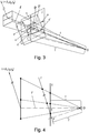
- a statistical estimate of a motion field based on the assignment of the individual temporally successive recorded pixels is created. From this, a global transport direction t is determined, which determines the direction of movement of a reference object 1 relative to the image acquisition unit 2 with respect to that in FIG Fig. 3 indicates the coordinate system shown.
- Such a method is basically known from the prior art and, for example, in ⁇ Tolc, S., Huber-Mörk, R., Hollander, B., & Soukup, D. (2014). Depth and all-in-focus images obtained by multi-line scan light-field approach. Proc. of SPIE-IS & T / Vol, 9024, 902407-1 specified.
- a considered object point appears at a first position as a pixel having the coordinates (x 1 , y 1 ).
- the further moving pixel now appears at a second position with the coordinates (x 2 , y 2 ), which, taking into account the camera parameters determined, is analogous to (X 1 , Y 1 , Z 1 ) as object point (X 2 , Y 2 , Z 2 ) can be determined in world coordinates.
- the horizontal cuts through the image stack in Fig. 2 are the reference images produced, the displacement of the image of the object point under consideration is to be tracked in the generated image recordings in the image stack from the position (x 1 , y 1 ) to the position (x 2 , y 2 ) which is also shown in the image acquisition unit 2 in FIG Fig. 1 sees.
- a sensor plane I is determined on the basis of the determined camera parameters.
- the sensor plane I is set so that it passes through the main point c, normal to the, the main point c and the camera center O connecting main vision beam r is aligned and the distance between the camera center O, the image pickup unit 2 and the main point c of the focal length equals f.
- a new image plane I ' is determined and determined as the next step.
- One of the coordinate directions v 'of the new image plane I' is parallel to the previously determined transport direction t.
- the normalized transport direction is determined by individual components (t 1 , t 2 , t 3 ) that indicate the orientation of the transport direction relative to the world coordinate system.
- the new image plane I ' is defined such that the image plane I' is rotated at a minimum angle to the sensor plane I, namely around the camera center O. That is, the angle between the normal vectors on the sensor plane I and the image plane I ' is minimal.
- the two further coordinate axes u ', w' enclose a right angle with each other and with v '.
- the vector w ' is normal to the image plane I'
- the vectors u 'and v' are in the image plane I 'and all three form an orthonormal system.
- This ensures that the scaling in the image from the sensor plane into the image plane I 'remains the same and the perspective distortion between the image points and pixels imaged in the sensor plane I in the new image plane I' is as low as possible.
- Another advantage of this choice is that in this new image plane, the Verschub axis is parallel.
- an image transformation H of the sensor plane I in the image plane I ' which is in particular a perspective mapping rule is determined, for each lying on the sensor plane I point p the intersection p' of this point p and the camera center O extending line with the Image plane I 'indicates, see Fig. 3 respectively.
- Fig. 3b an image transformation H of the sensor plane I in the image plane I ', which is in particular a perspective mapping rule is determined, for each lying on the sensor plane I point p the intersection p' of this point p and the camera center O extending line with the Image plane I 'indicates, see Fig. 3 respectively.
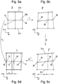
- each pixel with homogeneous coordinates (x ' i , y' j , 1) in the sensor plane I for example, the two pixels 10, 12, 15 assigned to the sensor row 21b, becomes Fig. 5a , projected onto the image plane I 'by the camera center O by means of the perspective image transformation H onto the new image plane I'.
- the index i describes the pixel positions along the respective sensor line 21a, 21b, 21c and the index j sets the respective sensor line 21a, 21b, 21c, in particular by specifying a line index.
- the image transformation H converts the pixels 10, 12 15 of the sensor plane I in Fig. 5a into the pixels 30, 32, 35 of the image plane I 'in Fig. 5b.
- Fig. 5b shows the application of image transformation H to multiple line captures of sensor lines 21a, 21b, 21c.
- the individual pixel positions of a respective line recording in the sensor plane I are imaged by the application of the image transformation H perspective distorted on the image plane I '.
- the image transformation H is a homography in the exemplary embodiment. This is a bijective mapping between projective planes or spaces, which maps all lines back to straight lines. In the process, squares, such as squares, are mapped onto general squares.
- a line transformation h 1 ,..., H 3 is to be created on the basis of the image matrix for the selected lines of the line sensors, which indicates how a predetermined line image a sensor line 21 a, 21 b, 21 c of the image recording unit 2 is imaged onto the image plane I , Using such a row transformation, a determined line pickup can be converted into a rectified line pickup.
- the row transformation h 1 ,..., H 3 is intended in each case to indicate how for each original pixel position 10, 12, 15 associated with each sensor row 21a, 21b, 21c of the image recording unit 2 rectified pixel positions 11, 13 in the sensor plane I of a given line recording , 16 are calculated in the sensor level I.
- the image transformation H is reduced to the original pixel positions 10, 12, 15 in the sensor plane I (FIG. Fig. 5a ) are applied so as to be transformed pixel positions 30, 32, 35 in the image plane I '(FIG. Fig. 5b ), where the u'-coordinates of associated pixels of different sensor lines are not necessarily the same.
- the transformed pixel positions 30 in the image plane I ' are adjusted by means of a repositioning R to cleaned pixel positions 31 (FIG. Fig. 5c ) in the image plane I 'whose u'-coordinate is equal to the u'-coordinate of associated points in sensor lines 31a, 31c.
- the transformed pixel positions 30, 32, 35 in the image plane I ' are adjusted by means of a repositioning R to cleaned pixel positions 31, 33, 36 (FIG. Fig. 5c ) in the image plane I 'whose distances are distributed uniformly along the sensor line to each other.
- Matched pixel positions 31a, 31, 31c of different sensor lines 21a, 21b, 21c have the same u'-coordinate.
- the v 'coordinate of the cleaned points (x''', y '') thus obtained, in Fig. 5c about 31, 33, 36 varies.
- Fig. 5c shows the application of repositioning R to multiple line captures of sensor lines 21a, 21b, 21c.
- rectified points (x "", y "") f / (x '''u 3 ' + y '''v 3 ' + fw 3 ') * (x''' u 1 '+ y'''v 1 ' + fw 1 ', x''' u 2 '+ y''' v 2 '+ fw 2 ').
- Fig. 5d It can be seen that all the image positions 10, 12, 15 and rectified pixel positions 11, 13, 16 that can be assigned to the same sensor line are at the same v coordinate and differ only in the u coordinate.
- an object 4 with the transport unit 3 is moved along the transport direction t through the recording area of the image recording unit 2 emotional.
- Fig. 1 For example, it may be a coin for which a three-dimensional reconstruction is to be performed on the basis of images of the image recording unit 2.
- a function which interpolates the determined brightness values is created in each case.
- brightness values are determined, for example, by linear combination of the brightness values of the original pixel positions 10, 12, 15 in the sensor plane I.
- the brightness values of the original pixel positions 10, 12, 15 in the sensor plane I are in the ratio in which the distances between the transformed pixel positions 30, 32, 35 determined using image transformation H in the image plane I 'are along a respectively considered row pickup , considered.
- the index i describes the pixel positions in the respective sensor row 21a, 21b, 21c.
- s and t respectively indicate the distance of the rectified pixel positions 11 to the respectively adjacent original image positions 15, 10 in the sensor plane I.
- s indicates the distance between the rectified pixel position 11 under consideration and the original pixel position 15 to the left thereof in the sensor plane I;
- t indicates the distance between the rectified pixel position 11 under consideration and the original pixel position 10 to the right of it in the sensor plane I.
- a rectified pixel on the sensor plane I is uniquely assigned to each object point with world coordinates, taking into account that the row alignment of the sensor rows 21a, 21b, 21c of the image acquisition unit 2 is at an angle to the transport direction t of the object 4, on which the object point in question is located. is aligned. This ensures that the epipolar condition is fulfilled in such a rectified image stack.
- a reference object 1 with known dimensions given in metric units for generating the reference recordings for determining the focal length f of the position of the main point c and the determination of the translation and rotation of the Reference object 1 with respect to the image pickup unit 2, as well as used to determine the transport direction t is possible to assign metric units to the brightness values derived from the respective pixels of each of the sensor lines 21a, 21b, 21c.
- an optionally existing camera or lens distortion can also be taken into account.
- the camera distortion k is determined by means of a known calibration method for area cameras.
- an equalization is performed on the pixels projected from the image plane I 'back into the sensor plane I.
Applications Claiming Priority (1)
| Application Number | Priority Date | Filing Date | Title |
|---|---|---|---|
| ATA50055/2018A AT520426B1 (de) | 2018-01-23 | 2018-01-23 | Verfahren zur Kalibrierung einer Bildaufnahmeeinheit |
Publications (2)
| Publication Number | Publication Date |
|---|---|
| EP3561772A1 true EP3561772A1 (fr) | 2019-10-30 |
| EP3561772B1 EP3561772B1 (fr) | 2021-07-07 |
Family
ID=64664169
Family Applications (1)
| Application Number | Title | Priority Date | Filing Date |
|---|---|---|---|
| EP18211356.3A Active EP3561772B1 (fr) | 2018-01-23 | 2018-12-10 | Procédé d'étalonnage d'une unité d'enregistrement d'images à balayage linéaire |
Country Status (2)
| Country | Link |
|---|---|
| EP (1) | EP3561772B1 (fr) |
| AT (1) | AT520426B1 (fr) |
Cited By (1)
| Publication number | Priority date | Publication date | Assignee | Title |
|---|---|---|---|---|
| EP3985608A1 (fr) | 2020-10-15 | 2022-04-20 | AIT Austrian Institute of Technology GmbH | Procédé mis en oeuvre par ordinateur permettant de créer des structures de données d'objets à dimensions multiples |
Citations (4)
| Publication number | Priority date | Publication date | Assignee | Title |
|---|---|---|---|---|
| DE102007009664B3 (de) * | 2007-02-22 | 2008-04-10 | Jena-Optronik Gmbh | Vorrichtung zur Kalibrierung von Zeilenkameras |
| EP2833323A2 (fr) * | 2013-08-01 | 2015-02-04 | Cognex Corporation | Association d'un code avec un objet |
| EP3062290A1 (fr) * | 2015-02-26 | 2016-08-31 | AIT Austrian Institute of Technology GmbH | Procede de determination d'une reproduction d'un objet |
| EP3128483A1 (fr) * | 2015-08-07 | 2017-02-08 | Omron Corporation | Appareil, procédé et programme d'étalonnage |
-
2018
- 2018-01-23 AT ATA50055/2018A patent/AT520426B1/de active
- 2018-12-10 EP EP18211356.3A patent/EP3561772B1/fr active Active
Patent Citations (4)
| Publication number | Priority date | Publication date | Assignee | Title |
|---|---|---|---|---|
| DE102007009664B3 (de) * | 2007-02-22 | 2008-04-10 | Jena-Optronik Gmbh | Vorrichtung zur Kalibrierung von Zeilenkameras |
| EP2833323A2 (fr) * | 2013-08-01 | 2015-02-04 | Cognex Corporation | Association d'un code avec un objet |
| EP3062290A1 (fr) * | 2015-02-26 | 2016-08-31 | AIT Austrian Institute of Technology GmbH | Procede de determination d'une reproduction d'un objet |
| EP3128483A1 (fr) * | 2015-08-07 | 2017-02-08 | Omron Corporation | Appareil, procédé et programme d'étalonnage |
Non-Patent Citations (2)
| Title |
|---|
| HABIB AYMAN ET AL: "Boresight Calibration of GNSS/INS-Assisted Push-Broom Hyperspectral Scanners on UAV Platforms", IEEE JOURNAL OF SELECTED TOPICS IN APPLIED EARTH OBSERVATIONS AND REMOTE SENSING, IEEE, USA, vol. 11, no. 5, 1 May 2018 (2018-05-01), pages 1734 - 1749, XP011682538, ISSN: 1939-1404, [retrieved on 20180427], DOI: 10.1109/JSTARS.2018.2813263 * |
| STOLC SVORAD ET AL: "Depth and all-in-focus imaging by a multi-line-scan light-field camera", JOURNAL OF ELECTRONIC IMAGING, S P I E - INTERNATIONAL SOCIETY FOR OPTICAL ENGINEERING, US, vol. 23, no. 5, 1 September 2014 (2014-09-01), pages 53020, XP060047706, ISSN: 1017-9909, [retrieved on 20141015], DOI: 10.1117/1.JEI.23.5.053020 * |
Cited By (1)
| Publication number | Priority date | Publication date | Assignee | Title |
|---|---|---|---|---|
| EP3985608A1 (fr) | 2020-10-15 | 2022-04-20 | AIT Austrian Institute of Technology GmbH | Procédé mis en oeuvre par ordinateur permettant de créer des structures de données d'objets à dimensions multiples |
Also Published As
| Publication number | Publication date |
|---|---|
| AT520426A4 (de) | 2019-04-15 |
| AT520426B1 (de) | 2019-04-15 |
| EP3561772B1 (fr) | 2021-07-07 |
Similar Documents
| Publication | Publication Date | Title |
|---|---|---|
| EP3479058A1 (fr) | Procédé et dispositif servant à mesurer des dommages subis par une carrosserie | |
| DE102014209137A1 (de) | Verfahren und Vorrichtung zur Kalibrierung eines Kamerasystems eines Kraftfahrzeugs | |
| DE10026201A1 (de) | Vorrichtung für die Bestimmung der Position eines Gegenstandes in einem OXZ-Bezugssystem | |
| DE102011003653A1 (de) | Verfahren zum Gewinnen eines 3D-Bilddatensatzes zu einem Bildobjekt | |
| WO2011009736A1 (fr) | Production d'un ensemble de données globales | |
| DE102018001969A1 (de) | Verfahren zur Kalibrierung eines kontaktanalogen Headup-Displays eines Fahrzeuges in einer Werkstatt | |
| DE10328523B4 (de) | Verfahren und Meßvorrichtung zur berührungslosen Vermessung einer Kontur einer Oberfläche | |
| DE102012023060A1 (de) | Verfahren zum Detektieren eines beweglichen Objekts mithilfe eines Histogramms anhand von Bildern einer Kamera und Kamerasystem für ein Kraftfahrzeug | |
| EP3561772B1 (fr) | Procédé d'étalonnage d'une unité d'enregistrement d'images à balayage linéaire | |
| EP0897247A2 (fr) | Procédé de calcul de vecteurs de mouvement | |
| EP1098268A2 (fr) | Méthode pour la mésure optique tridimensionelle de surfaces d'objets | |
| EP3420533B1 (fr) | Procédé d'étalonnage d'un système de mesure optique | |
| DE102010021221A1 (de) | Verfahren zur Bestimmung einer Ausrichtung einer an einem Fahrzeug angeordneten Kamera | |
| EP0623884A2 (fr) | Procédé et appareil pour la détermination quantitative des déformations dans des images radiographiques | |
| EP2902963B1 (fr) | Procédé de fabrication d'une représentation d'un objet | |
| EP3518180B1 (fr) | Procédé de création d'une structure de données de piles d'images | |
| DE3903838C2 (fr) | ||
| EP3985608B1 (fr) | Procédé mis en oeuvre par ordinateur permettant de créer des structures de données d'objets à dimensions multiples | |
| DE112019002126T5 (de) | Positionsschätzungsvorrichtung, positionsschätzungsverfahren und programm dafür | |
| DE102019212022A1 (de) | Verfahren und Vorrichtung zum Feststellen eines Parallaxenproblems in Sensordaten zweier Sensoren | |
| DE3446009C2 (fr) | ||
| DE102018209366B4 (de) | Verfahren zur Bestimmung einer Position und/oder Orientierung einer Einrichtung | |
| EP2420797A2 (fr) | Procédé de numérisation en 3D d'un objet doté d'une surface variable | |
| DE19630194B4 (de) | Verfahren zur Detektion von Objekten | |
| DE202022001640U1 (de) | Fahrzeugoberflächenanalysevorrichtung |
Legal Events
| Date | Code | Title | Description |
|---|---|---|---|
| PUAI | Public reference made under article 153(3) epc to a published international application that has entered the european phase |
Free format text: ORIGINAL CODE: 0009012 |
|
| STAA | Information on the status of an ep patent application or granted ep patent |
Free format text: STATUS: THE APPLICATION HAS BEEN PUBLISHED |
|
| AK | Designated contracting states |
Kind code of ref document: A1 Designated state(s): AL AT BE BG CH CY CZ DE DK EE ES FI FR GB GR HR HU IE IS IT LI LT LU LV MC MK MT NL NO PL PT RO RS SE SI SK SM TR |
|
| AX | Request for extension of the european patent |
Extension state: BA ME |
|
| STAA | Information on the status of an ep patent application or granted ep patent |
Free format text: STATUS: REQUEST FOR EXAMINATION WAS MADE |
|
| STAA | Information on the status of an ep patent application or granted ep patent |
Free format text: STATUS: EXAMINATION IS IN PROGRESS |
|
| 17P | Request for examination filed |
Effective date: 20200331 |
|
| RBV | Designated contracting states (corrected) |
Designated state(s): AL AT BE BG CH CY CZ DE DK EE ES FI FR GB GR HR HU IE IS IT LI LT LU LV MC MK MT NL NO PL PT RO RS SE SI SK SM TR |
|
| 17Q | First examination report despatched |
Effective date: 20200430 |
|
| STAA | Information on the status of an ep patent application or granted ep patent |
Free format text: STATUS: EXAMINATION IS IN PROGRESS |
|
| GRAP | Despatch of communication of intention to grant a patent |
Free format text: ORIGINAL CODE: EPIDOSNIGR1 |
|
| STAA | Information on the status of an ep patent application or granted ep patent |
Free format text: STATUS: GRANT OF PATENT IS INTENDED |
|
| INTG | Intention to grant announced |
Effective date: 20210303 |
|
| GRAS | Grant fee paid |
Free format text: ORIGINAL CODE: EPIDOSNIGR3 |
|
| GRAA | (expected) grant |
Free format text: ORIGINAL CODE: 0009210 |
|
| STAA | Information on the status of an ep patent application or granted ep patent |
Free format text: STATUS: THE PATENT HAS BEEN GRANTED |
|
| AK | Designated contracting states |
Kind code of ref document: B1 Designated state(s): AL AT BE BG CH CY CZ DE DK EE ES FI FR GB GR HR HU IE IS IT LI LT LU LV MC MK MT NL NO PL PT RO RS SE SI SK SM TR |
|
| REG | Reference to a national code |
Ref country code: GB Ref legal event code: FG4D Free format text: NOT ENGLISH |
|
| REG | Reference to a national code |
Ref country code: AT Ref legal event code: REF Ref document number: 1409325 Country of ref document: AT Kind code of ref document: T Effective date: 20210715 |
|
| REG | Reference to a national code |
Ref country code: DE Ref legal event code: R096 Ref document number: 502018006004 Country of ref document: DE |
|
| REG | Reference to a national code |
Ref country code: IE Ref legal event code: FG4D Free format text: LANGUAGE OF EP DOCUMENT: GERMAN |
|
| REG | Reference to a national code |
Ref country code: LT Ref legal event code: MG9D |
|
| REG | Reference to a national code |
Ref country code: NL Ref legal event code: MP Effective date: 20210707 |
|
| PG25 | Lapsed in a contracting state [announced via postgrant information from national office to epo] |
Ref country code: ES Free format text: LAPSE BECAUSE OF FAILURE TO SUBMIT A TRANSLATION OF THE DESCRIPTION OR TO PAY THE FEE WITHIN THE PRESCRIBED TIME-LIMIT Effective date: 20210707 Ref country code: FI Free format text: LAPSE BECAUSE OF FAILURE TO SUBMIT A TRANSLATION OF THE DESCRIPTION OR TO PAY THE FEE WITHIN THE PRESCRIBED TIME-LIMIT Effective date: 20210707 Ref country code: HR Free format text: LAPSE BECAUSE OF FAILURE TO SUBMIT A TRANSLATION OF THE DESCRIPTION OR TO PAY THE FEE WITHIN THE PRESCRIBED TIME-LIMIT Effective date: 20210707 Ref country code: RS Free format text: LAPSE BECAUSE OF FAILURE TO SUBMIT A TRANSLATION OF THE DESCRIPTION OR TO PAY THE FEE WITHIN THE PRESCRIBED TIME-LIMIT Effective date: 20210707 Ref country code: SE Free format text: LAPSE BECAUSE OF FAILURE TO SUBMIT A TRANSLATION OF THE DESCRIPTION OR TO PAY THE FEE WITHIN THE PRESCRIBED TIME-LIMIT Effective date: 20210707 Ref country code: NL Free format text: LAPSE BECAUSE OF FAILURE TO SUBMIT A TRANSLATION OF THE DESCRIPTION OR TO PAY THE FEE WITHIN THE PRESCRIBED TIME-LIMIT Effective date: 20210707 Ref country code: NO Free format text: LAPSE BECAUSE OF FAILURE TO SUBMIT A TRANSLATION OF THE DESCRIPTION OR TO PAY THE FEE WITHIN THE PRESCRIBED TIME-LIMIT Effective date: 20211007 Ref country code: PT Free format text: LAPSE BECAUSE OF FAILURE TO SUBMIT A TRANSLATION OF THE DESCRIPTION OR TO PAY THE FEE WITHIN THE PRESCRIBED TIME-LIMIT Effective date: 20211108 Ref country code: BG Free format text: LAPSE BECAUSE OF FAILURE TO SUBMIT A TRANSLATION OF THE DESCRIPTION OR TO PAY THE FEE WITHIN THE PRESCRIBED TIME-LIMIT Effective date: 20211007 Ref country code: LT Free format text: LAPSE BECAUSE OF FAILURE TO SUBMIT A TRANSLATION OF THE DESCRIPTION OR TO PAY THE FEE WITHIN THE PRESCRIBED TIME-LIMIT Effective date: 20210707 |
|
| PG25 | Lapsed in a contracting state [announced via postgrant information from national office to epo] |
Ref country code: PL Free format text: LAPSE BECAUSE OF FAILURE TO SUBMIT A TRANSLATION OF THE DESCRIPTION OR TO PAY THE FEE WITHIN THE PRESCRIBED TIME-LIMIT Effective date: 20210707 Ref country code: LV Free format text: LAPSE BECAUSE OF FAILURE TO SUBMIT A TRANSLATION OF THE DESCRIPTION OR TO PAY THE FEE WITHIN THE PRESCRIBED TIME-LIMIT Effective date: 20210707 Ref country code: GR Free format text: LAPSE BECAUSE OF FAILURE TO SUBMIT A TRANSLATION OF THE DESCRIPTION OR TO PAY THE FEE WITHIN THE PRESCRIBED TIME-LIMIT Effective date: 20211008 |
|
| REG | Reference to a national code |
Ref country code: DE Ref legal event code: R097 Ref document number: 502018006004 Country of ref document: DE |
|
| PG25 | Lapsed in a contracting state [announced via postgrant information from national office to epo] |
Ref country code: DK Free format text: LAPSE BECAUSE OF FAILURE TO SUBMIT A TRANSLATION OF THE DESCRIPTION OR TO PAY THE FEE WITHIN THE PRESCRIBED TIME-LIMIT Effective date: 20210707 |
|
| PLBE | No opposition filed within time limit |
Free format text: ORIGINAL CODE: 0009261 |
|
| STAA | Information on the status of an ep patent application or granted ep patent |
Free format text: STATUS: NO OPPOSITION FILED WITHIN TIME LIMIT |
|
| PG25 | Lapsed in a contracting state [announced via postgrant information from national office to epo] |
Ref country code: SM Free format text: LAPSE BECAUSE OF FAILURE TO SUBMIT A TRANSLATION OF THE DESCRIPTION OR TO PAY THE FEE WITHIN THE PRESCRIBED TIME-LIMIT Effective date: 20210707 Ref country code: SK Free format text: LAPSE BECAUSE OF FAILURE TO SUBMIT A TRANSLATION OF THE DESCRIPTION OR TO PAY THE FEE WITHIN THE PRESCRIBED TIME-LIMIT Effective date: 20210707 Ref country code: RO Free format text: LAPSE BECAUSE OF FAILURE TO SUBMIT A TRANSLATION OF THE DESCRIPTION OR TO PAY THE FEE WITHIN THE PRESCRIBED TIME-LIMIT Effective date: 20210707 Ref country code: EE Free format text: LAPSE BECAUSE OF FAILURE TO SUBMIT A TRANSLATION OF THE DESCRIPTION OR TO PAY THE FEE WITHIN THE PRESCRIBED TIME-LIMIT Effective date: 20210707 Ref country code: CZ Free format text: LAPSE BECAUSE OF FAILURE TO SUBMIT A TRANSLATION OF THE DESCRIPTION OR TO PAY THE FEE WITHIN THE PRESCRIBED TIME-LIMIT Effective date: 20210707 Ref country code: AL Free format text: LAPSE BECAUSE OF FAILURE TO SUBMIT A TRANSLATION OF THE DESCRIPTION OR TO PAY THE FEE WITHIN THE PRESCRIBED TIME-LIMIT Effective date: 20210707 |
|
| 26N | No opposition filed |
Effective date: 20220408 |
|
| PG25 | Lapsed in a contracting state [announced via postgrant information from national office to epo] |
Ref country code: MC Free format text: LAPSE BECAUSE OF FAILURE TO SUBMIT A TRANSLATION OF THE DESCRIPTION OR TO PAY THE FEE WITHIN THE PRESCRIBED TIME-LIMIT Effective date: 20210707 Ref country code: IT Free format text: LAPSE BECAUSE OF FAILURE TO SUBMIT A TRANSLATION OF THE DESCRIPTION OR TO PAY THE FEE WITHIN THE PRESCRIBED TIME-LIMIT Effective date: 20210707 |
|
| REG | Reference to a national code |
Ref country code: CH Ref legal event code: PL |
|
| REG | Reference to a national code |
Ref country code: BE Ref legal event code: MM Effective date: 20211231 |
|
| PG25 | Lapsed in a contracting state [announced via postgrant information from national office to epo] |
Ref country code: LU Free format text: LAPSE BECAUSE OF NON-PAYMENT OF DUE FEES Effective date: 20211210 Ref country code: IE Free format text: LAPSE BECAUSE OF NON-PAYMENT OF DUE FEES Effective date: 20211210 |
|
| PG25 | Lapsed in a contracting state [announced via postgrant information from national office to epo] |
Ref country code: BE Free format text: LAPSE BECAUSE OF NON-PAYMENT OF DUE FEES Effective date: 20211231 |
|
| PG25 | Lapsed in a contracting state [announced via postgrant information from national office to epo] |
Ref country code: LI Free format text: LAPSE BECAUSE OF NON-PAYMENT OF DUE FEES Effective date: 20211231 Ref country code: CH Free format text: LAPSE BECAUSE OF NON-PAYMENT OF DUE FEES Effective date: 20211231 |
|
| PG25 | Lapsed in a contracting state [announced via postgrant information from national office to epo] |
Ref country code: CY Free format text: LAPSE BECAUSE OF FAILURE TO SUBMIT A TRANSLATION OF THE DESCRIPTION OR TO PAY THE FEE WITHIN THE PRESCRIBED TIME-LIMIT Effective date: 20210707 |
|
| PG25 | Lapsed in a contracting state [announced via postgrant information from national office to epo] |
Ref country code: HU Free format text: LAPSE BECAUSE OF FAILURE TO SUBMIT A TRANSLATION OF THE DESCRIPTION OR TO PAY THE FEE WITHIN THE PRESCRIBED TIME-LIMIT; INVALID AB INITIO Effective date: 20181210 |
|
| PGFP | Annual fee paid to national office [announced via postgrant information from national office to epo] |
Ref country code: GB Payment date: 20231220 Year of fee payment: 6 |
|
| PGFP | Annual fee paid to national office [announced via postgrant information from national office to epo] |
Ref country code: FR Payment date: 20231222 Year of fee payment: 6 Ref country code: DE Payment date: 20231214 Year of fee payment: 6 |
|
| PG25 | Lapsed in a contracting state [announced via postgrant information from national office to epo] |
Ref country code: MK Free format text: LAPSE BECAUSE OF FAILURE TO SUBMIT A TRANSLATION OF THE DESCRIPTION OR TO PAY THE FEE WITHIN THE PRESCRIBED TIME-LIMIT Effective date: 20210707 |