EP3561772A1 - Method for calibrating an linescanning image recording unit - Google Patents
Method for calibrating an linescanning image recording unit Download PDFInfo
- Publication number
- EP3561772A1 EP3561772A1 EP18211356.3A EP18211356A EP3561772A1 EP 3561772 A1 EP3561772 A1 EP 3561772A1 EP 18211356 A EP18211356 A EP 18211356A EP 3561772 A1 EP3561772 A1 EP 3561772A1
- Authority
- EP
- European Patent Office
- Prior art keywords
- sensor
- image
- plane
- determined
- pixel positions
- Prior art date
- Legal status (The legal status is an assumption and is not a legal conclusion. Google has not performed a legal analysis and makes no representation as to the accuracy of the status listed.)
- Granted
Links
- 238000000034 method Methods 0.000 title claims abstract description 35
- 230000009466 transformation Effects 0.000 claims abstract description 37
- 238000013519 translation Methods 0.000 claims abstract description 7
- 238000013507 mapping Methods 0.000 claims abstract description 6
- 238000011156 evaluation Methods 0.000 claims description 3
- 230000000007 visual effect Effects 0.000 abstract 1
- 239000013598 vector Substances 0.000 description 7
- 239000011159 matrix material Substances 0.000 description 4
- 238000012546 transfer Methods 0.000 description 4
- 238000013459 approach Methods 0.000 description 1
- 238000006073 displacement reaction Methods 0.000 description 1
- 230000002996 emotional effect Effects 0.000 description 1
- 238000003384 imaging method Methods 0.000 description 1
- 238000004519 manufacturing process Methods 0.000 description 1
- 230000002123 temporal effect Effects 0.000 description 1
Images


Classifications
-
- H—ELECTRICITY
- H04—ELECTRIC COMMUNICATION TECHNIQUE
- H04N—PICTORIAL COMMUNICATION, e.g. TELEVISION
- H04N13/00—Stereoscopic video systems; Multi-view video systems; Details thereof
- H04N13/20—Image signal generators
- H04N13/204—Image signal generators using stereoscopic image cameras
- H04N13/246—Calibration of cameras
-
- G—PHYSICS
- G06—COMPUTING; CALCULATING OR COUNTING
- G06T—IMAGE DATA PROCESSING OR GENERATION, IN GENERAL
- G06T7/00—Image analysis
- G06T7/70—Determining position or orientation of objects or cameras
- G06T7/73—Determining position or orientation of objects or cameras using feature-based methods
-
- G—PHYSICS
- G06—COMPUTING; CALCULATING OR COUNTING
- G06T—IMAGE DATA PROCESSING OR GENERATION, IN GENERAL
- G06T7/00—Image analysis
- G06T7/80—Analysis of captured images to determine intrinsic or extrinsic camera parameters, i.e. camera calibration
Definitions
- the invention relates to a method for calibrating an image recording unit according to the preamble of patent claim 1 and to a method for recording images according to patent claim 3.
- methods for geometrically calibrating surface cameras ie for determining intrinsic camera parameters such as, for example, the focal length or the position of the main point and extrinsic camera parameters, such as, for example, the translation and rotation of a reference object with respect to the image acquisition unit, are known from the prior art
- methods of geometrically calibrating image acquisition units that have a number of sensor lines and also calculate intrinsic and extrinsic camera parameters, but assume that the transport is along a straight line that is parallel to the sensor plane and orthogonal to the read lines.
- the object of the invention is therefore to remedy this situation and to provide a method for calibrating an image acquisition unit with which can be taken into account in a simple manner and quickly and reliably during the calibration, that the line orientation of the image pickup unit and the transport direction of a male object include an angle and such rectified images of the subject matter are provided.
- a method according to the invention for the acquisition of images in order to easily produce a rectified image stack or to produce rectified line images in which the epipolar condition is met, provision is made for an object with the transport unit to travel along the transport direction, following the inventive calibration of the image acquisition unit the receiving area of the image recording unit is moved and with a selected number of sensor rows during the movement of the object respectively line recordings are created and the individual line recordings are separately subjected to the respective sensor line associated row transformation.
- the brightness values of their in the sensor plane are determined within the line transformation to determine a brightness value for a respective rectified pixel position in the sensor plane associated with a sensor line are respectively interpolated adjacent to each other original pixel positions, in particular linearly combined in that distance ratio, which has a respectively considered rectified pixel position to its adjacent original pixel positions, which are assigned to the same sensor line.
- the image acquisition unit scans an object evenly from all directions along the sensor lines as often as possible, it can be provided in a method for recording images that rectified line images are created by respectively creating a function that interpolates the brightness values determined for the created line images and evaluating this function at a number of positions whose images are distributed equidistantly or according to another specification in the image plane under the image transformation, and the results of this evaluation are assigned to the rectified line image.
- Assigning metric units in the pixel values of an image recording unit with sensor lines can be provided in a method according to the invention, that a reference object with known dimensions given in metric units is used, and metric units are assigned to the brightness values derived from the respective pixels of each of the sensor lines.
- the in Fig. 1 The structure shown for carrying out a method according to the invention for calibrating an image recording unit 2 or for recording images comprises an image recording unit 2 which has a number of sensor lines 21a, 21b, 21c.
- the sensor lines 21a, 21b, 21c of the image acquisition unit 2 can also form individual selected lines of a surface sensor.
- Each of the sensor pixels of the sensor lines has a u-coordinate in the row direction u.
- the sensor pixels belonging to the same sensor line have the same v-coordinate with respect to the area sensor Embodiment, the image pickup unit 2 comprises three sensor lines 21a, 21b, 21c.
- the sensor lines 21a, 21b, 21c are directed to a region of the reference object 1 for receiving a reference object 1.
- the reference object 1 is transported by a transport unit 3 through the receiving area of the image recording unit 2.
- Such a structure is also capable of taking pictures of an object 4 deviating from the reference object 1 by means of the image pickup unit 2 while the article 4 is being transported through the pickup area of the image pickup unit 2.
- Such an article 4 can be, for example, a coin, as it is in Fig. 1 is shown schematically.
- the row alignment of the sensor rows 21a, 21b, 21c is arranged at an angle or normal to the transport direction t, and the sensor rows 21a, 21b, 21c are arranged one behind the other in the transport direction t, in particular parallel to each other.
- the sensor rows in the row direction are not offset from one another and / or oriented so that the respective first pixels of the sensor rows 21a, 21b, 21c lie on a straight line which is oriented approximately in the transport direction t. At most, this straight line can also be at a predetermined angle to the transport direction.
- a reference object 1 is transported by means of the transport unit 3 through the receiving area of the image recording unit 2.
- Each of the sensor lines 21a, 21b, 21c creates during the transport along the transport direction t recordings of the reference object 1 under different recording angles.
- three pickups are available for the individual item items of the reference item, each of which shows the respective item point taken by each of the sensor row 21a, 21b, 21c from a different angle.
- this can also be positioned and moved manually in the recording area of the image recording unit 2. Also, by another device, the position and position of the reference object 1 with respect to the image pickup unit 2 can be selected at random and, if necessary, moved by the pickup area of the image pickup unit 2.
- the alignment of the sensor lines 21a, 21b, 21c of the image pickup unit 2 is not normal, but is oriented at an angle deviating from the right angle to the transport direction t. Therefore, the individual images of the same object point are imaged in the individual images of sensor pixels of the sensor lines determined during the movement, which are located at different positions in the sensor direction or have a different u-coordinate relative to the surface sensor. The images of an object point are therefore - unlike expected - not in sensor pixels, each with the same u-coordinates again.
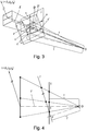
- Fig. 2 shows a schematic representation of the image stack, which is received by the image pickup unit 2.
- a horizontal section through this image stack is a surface image of the sensor at a time, the temporal component is the z-direction.
- the left vertical cut in uz-direction corresponds to the recording of a sensor line 21a over a certain period of time.
- the image of an object point of the reference object 1 is recorded with different sensor lines 21a, 21b, 21c respectively at different u-positions in the images of the sensor lines at different times, ie different z coordinates.
- These individual images are as in Fig. 2 represented, generally on straight lines. If there is additionally lens distortion, these images may be on general curves.
- the distance that a respective pixel moves along the z-direction of this straight line is directly proportional to the distance of the object point imaged thereby from the image acquisition unit 2. In a possible three-dimensional reconstruction of the reference object 1 or another object 4 on the basis of acquired images, this can be taken into account. It can also be made a transfer of pixel spacing in metric units.
- the image recording unit 2 or its sensor lines 21a, 21b, 21c are oriented at an angle relative to the transport direction t, the trajectories of a point do not run parallel to the vz plane of this image stack, i. the u-coordinates of the point vary.
- a reference object 1 is moved several times with different orientation with the transport unit 3 along the transport direction t through the receiving area of the image recording unit 2.
- reference images of the reference object 1 are created for each of the orientations by the image acquisition unit 2.
- Each reference photograph of the reference object 1 consists of rows of pixels, each of the rows being created by a different sensor row 21a, 21b, 21c.
- the reference object 1 is a flat object on which, for example, a grid or punctiform calibration pattern is printed.
- the focal length f, the position of the main point c and possibly a distortion vector k of the image acquisition unit 2, that is to say the intrinsic camera parameters of the image acquisition unit 2, are determined from the reference images of the reference image 1 thus produced using a calibration method for area sensors known from the prior art.
- a reference object 1 with a special calibration pattern can be used to determine the camera parameters of the image acquisition unit 2.
- the reference object 1 is brought into a first position by means of the transport unit 3 and a reference image is taken with the image recording unit 2.
- An object point on the reference object 1 is thus characterized by two coordinates (x 1 , y 1 ) in the two-dimensional image of the reference object 1, ie in the reference image ( FIG. Fig. 2 ). If this method step is carried out for many points in specific positions on the reference object, the intrinsic camera parameters represented in the form of the camera matrix P and the extrinsic camera parameters as the rotation matrix R and position vector T can be indicated therefrom.
- a coordinate axis of the world coordinate system coincides with the main vision beam r, which runs from the camera center O to the main point c, while the other two coordinate axes enclose with this a right angle and are also at a right angle to each other.
- the reference object 1 is moved along the transporting direction t through the receiving area of the image pickup unit 2, again Reference shots are created, or a predetermined number of previously created reference shots is used.
- the reference images pixels from different sensor lines 21a, 21b, 21c are respectively detected and assigned to one another, which contain images of the same object point of the reference object 1 in the temporally successive reference images.
- a statistical estimate of a motion field based on the assignment of the individual temporally successive recorded pixels is created. From this, a global transport direction t is determined, which determines the direction of movement of a reference object 1 relative to the image acquisition unit 2 with respect to that in FIG Fig. 3 indicates the coordinate system shown.
- Such a method is basically known from the prior art and, for example, in ⁇ Tolc, S., Huber-Mörk, R., Hollander, B., & Soukup, D. (2014). Depth and all-in-focus images obtained by multi-line scan light-field approach. Proc. of SPIE-IS & T / Vol, 9024, 902407-1 specified.
- a considered object point appears at a first position as a pixel having the coordinates (x 1 , y 1 ).
- the further moving pixel now appears at a second position with the coordinates (x 2 , y 2 ), which, taking into account the camera parameters determined, is analogous to (X 1 , Y 1 , Z 1 ) as object point (X 2 , Y 2 , Z 2 ) can be determined in world coordinates.
- the horizontal cuts through the image stack in Fig. 2 are the reference images produced, the displacement of the image of the object point under consideration is to be tracked in the generated image recordings in the image stack from the position (x 1 , y 1 ) to the position (x 2 , y 2 ) which is also shown in the image acquisition unit 2 in FIG Fig. 1 sees.
- a sensor plane I is determined on the basis of the determined camera parameters.
- the sensor plane I is set so that it passes through the main point c, normal to the, the main point c and the camera center O connecting main vision beam r is aligned and the distance between the camera center O, the image pickup unit 2 and the main point c of the focal length equals f.
- a new image plane I ' is determined and determined as the next step.
- One of the coordinate directions v 'of the new image plane I' is parallel to the previously determined transport direction t.
- the normalized transport direction is determined by individual components (t 1 , t 2 , t 3 ) that indicate the orientation of the transport direction relative to the world coordinate system.
- the new image plane I ' is defined such that the image plane I' is rotated at a minimum angle to the sensor plane I, namely around the camera center O. That is, the angle between the normal vectors on the sensor plane I and the image plane I ' is minimal.
- the two further coordinate axes u ', w' enclose a right angle with each other and with v '.
- the vector w ' is normal to the image plane I'
- the vectors u 'and v' are in the image plane I 'and all three form an orthonormal system.
- This ensures that the scaling in the image from the sensor plane into the image plane I 'remains the same and the perspective distortion between the image points and pixels imaged in the sensor plane I in the new image plane I' is as low as possible.
- Another advantage of this choice is that in this new image plane, the Verschub axis is parallel.
- an image transformation H of the sensor plane I in the image plane I ' which is in particular a perspective mapping rule is determined, for each lying on the sensor plane I point p the intersection p' of this point p and the camera center O extending line with the Image plane I 'indicates, see Fig. 3 respectively.
- Fig. 3b an image transformation H of the sensor plane I in the image plane I ', which is in particular a perspective mapping rule is determined, for each lying on the sensor plane I point p the intersection p' of this point p and the camera center O extending line with the Image plane I 'indicates, see Fig. 3 respectively.
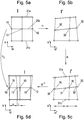
- each pixel with homogeneous coordinates (x ' i , y' j , 1) in the sensor plane I for example, the two pixels 10, 12, 15 assigned to the sensor row 21b, becomes Fig. 5a , projected onto the image plane I 'by the camera center O by means of the perspective image transformation H onto the new image plane I'.
- the index i describes the pixel positions along the respective sensor line 21a, 21b, 21c and the index j sets the respective sensor line 21a, 21b, 21c, in particular by specifying a line index.
- the image transformation H converts the pixels 10, 12 15 of the sensor plane I in Fig. 5a into the pixels 30, 32, 35 of the image plane I 'in Fig. 5b.
- Fig. 5b shows the application of image transformation H to multiple line captures of sensor lines 21a, 21b, 21c.
- the individual pixel positions of a respective line recording in the sensor plane I are imaged by the application of the image transformation H perspective distorted on the image plane I '.
- the image transformation H is a homography in the exemplary embodiment. This is a bijective mapping between projective planes or spaces, which maps all lines back to straight lines. In the process, squares, such as squares, are mapped onto general squares.
- a line transformation h 1 ,..., H 3 is to be created on the basis of the image matrix for the selected lines of the line sensors, which indicates how a predetermined line image a sensor line 21 a, 21 b, 21 c of the image recording unit 2 is imaged onto the image plane I , Using such a row transformation, a determined line pickup can be converted into a rectified line pickup.
- the row transformation h 1 ,..., H 3 is intended in each case to indicate how for each original pixel position 10, 12, 15 associated with each sensor row 21a, 21b, 21c of the image recording unit 2 rectified pixel positions 11, 13 in the sensor plane I of a given line recording , 16 are calculated in the sensor level I.
- the image transformation H is reduced to the original pixel positions 10, 12, 15 in the sensor plane I (FIG. Fig. 5a ) are applied so as to be transformed pixel positions 30, 32, 35 in the image plane I '(FIG. Fig. 5b ), where the u'-coordinates of associated pixels of different sensor lines are not necessarily the same.
- the transformed pixel positions 30 in the image plane I ' are adjusted by means of a repositioning R to cleaned pixel positions 31 (FIG. Fig. 5c ) in the image plane I 'whose u'-coordinate is equal to the u'-coordinate of associated points in sensor lines 31a, 31c.
- the transformed pixel positions 30, 32, 35 in the image plane I ' are adjusted by means of a repositioning R to cleaned pixel positions 31, 33, 36 (FIG. Fig. 5c ) in the image plane I 'whose distances are distributed uniformly along the sensor line to each other.
- Matched pixel positions 31a, 31, 31c of different sensor lines 21a, 21b, 21c have the same u'-coordinate.
- the v 'coordinate of the cleaned points (x''', y '') thus obtained, in Fig. 5c about 31, 33, 36 varies.
- Fig. 5c shows the application of repositioning R to multiple line captures of sensor lines 21a, 21b, 21c.
- rectified points (x "", y "") f / (x '''u 3 ' + y '''v 3 ' + fw 3 ') * (x''' u 1 '+ y'''v 1 ' + fw 1 ', x''' u 2 '+ y''' v 2 '+ fw 2 ').
- Fig. 5d It can be seen that all the image positions 10, 12, 15 and rectified pixel positions 11, 13, 16 that can be assigned to the same sensor line are at the same v coordinate and differ only in the u coordinate.
- an object 4 with the transport unit 3 is moved along the transport direction t through the recording area of the image recording unit 2 emotional.
- Fig. 1 For example, it may be a coin for which a three-dimensional reconstruction is to be performed on the basis of images of the image recording unit 2.
- a function which interpolates the determined brightness values is created in each case.
- brightness values are determined, for example, by linear combination of the brightness values of the original pixel positions 10, 12, 15 in the sensor plane I.
- the brightness values of the original pixel positions 10, 12, 15 in the sensor plane I are in the ratio in which the distances between the transformed pixel positions 30, 32, 35 determined using image transformation H in the image plane I 'are along a respectively considered row pickup , considered.
- the index i describes the pixel positions in the respective sensor row 21a, 21b, 21c.
- s and t respectively indicate the distance of the rectified pixel positions 11 to the respectively adjacent original image positions 15, 10 in the sensor plane I.
- s indicates the distance between the rectified pixel position 11 under consideration and the original pixel position 15 to the left thereof in the sensor plane I;
- t indicates the distance between the rectified pixel position 11 under consideration and the original pixel position 10 to the right of it in the sensor plane I.
- a rectified pixel on the sensor plane I is uniquely assigned to each object point with world coordinates, taking into account that the row alignment of the sensor rows 21a, 21b, 21c of the image acquisition unit 2 is at an angle to the transport direction t of the object 4, on which the object point in question is located. is aligned. This ensures that the epipolar condition is fulfilled in such a rectified image stack.
- a reference object 1 with known dimensions given in metric units for generating the reference recordings for determining the focal length f of the position of the main point c and the determination of the translation and rotation of the Reference object 1 with respect to the image pickup unit 2, as well as used to determine the transport direction t is possible to assign metric units to the brightness values derived from the respective pixels of each of the sensor lines 21a, 21b, 21c.
- an optionally existing camera or lens distortion can also be taken into account.
- the camera distortion k is determined by means of a known calibration method for area cameras.
- an equalization is performed on the pixels projected from the image plane I 'back into the sensor plane I.
Landscapes
- Engineering & Computer Science (AREA)
- Computer Vision & Pattern Recognition (AREA)
- Physics & Mathematics (AREA)
- General Physics & Mathematics (AREA)
- Theoretical Computer Science (AREA)
- Multimedia (AREA)
- Signal Processing (AREA)
- Studio Devices (AREA)
- Image Processing (AREA)
Abstract
Die Erfindung betrifft ein Verfahren zur Kalibrierung einer Bildaufnahmeeinheit (2), wobei die Bildaufnahmeeinheit (2) über eine Anzahl von Sensorzeilen (21a, 21b, 21c) mit einer Zeilenausrichtung in einem Winkel oder normal zur Transportrichtung (t) des Referenzgegenstands (1) verfügt, die in Transportrichtung (t) hintereinander, insbesondere parallel zueinander ausgerichtet, angeordnet sind, insbesondere Zeilen eines Flächensensors bilden,wobeia) ein Referenzgegenstand (1) mehrfach jeweils mit unterschiedlicher Ausrichtung, insbesondere mit einer Transporteinheit (3), entlang einer Transportrichtung (t) durch den Aufnahmebereich einer Bildaufnahmeeinheit (2) bewegt wird, und von der Bildaufnahmeeinheit (2) für jede der Ausrichtungen des Referenzgegenstands (1) jeweils Referenzaufnahmen erstellt werden, undb) aus diesen Referenzaufnahmen die Brennweite (f), die Position des Hauptpunktes (c) der Bildaufnahmeeinheit (2) und die Translation und Rotation des Referenzgegenstands (1) in Bezug auf die Bildaufnahmeeinheit (2) ermittelt werden,c) ein Referenzgegenstand (1) entlang der Transportrichtung (t) durch den Aufnahmebereich einer Bildaufnahmeeinheit (2) bewegt und Referenzaufnahmen erstellt werden, oder eine vorgegebene Anzahl der in Schritt a) erstellten Referenzaufnahmen herangezogen wird, die im Rahmen der Bewegung entlang der Transportrichtung (t) durch den Aufnahmebereich einer Bildaufnahmeeinheit (2) erstellt wurden,wobei Bildpunkte aus unterschiedlichen Sensorzeilen (21a, 21b, 21c) in den zeitlich aufeinanderfolgend erstellten Referenzaufnahmen detektiert und einander zugeordnet werden, die Abbilder desselben Gegenstandspunkts des Referenzgegenstands (1) enthalten,d) eine statistische Schätzung eines Bewegungsfelds basierend auf der Zuordnung der einzelnen zeitlich aufeinanderfolgend aufgenommenen Bildpunkte erstellt wird, und daraus eine globale Transportrichtung (t) ermittelt wird, die die Bewegungsrichtung des Referenzgegenstands (1) gegenüber der Bildaufnahmeeinheit (2) angibt, wobeie) eine Sensorebene (I) aufgrund der ermittelten Kameraparameter bestimmt wird,wobei- die Sensorebene (I) durch den Hauptpunkt (c) verläuft,- die Sensorebene (I) normal auf den den Hauptpunkt (c) und das Kamerazentrum (O) verbindenden Hauptsehstrahl (r) ausgerichtet ist,- und der Abstand zwischen dem Kamerazentrum (O) der Bildaufnahmeeinheit (2) und dem Hauptpunkt (c) der Brennweite (f) entspricht,f) eine neue Bildebene (I') derart ermittelt und festgelegt wird, dass eine der Koordinatenrichtungen (v') der neuen Bildebene (I') parallel zur Transportrichtung (t) ist,- insbesondere, derart,- dass die Bildebene (I') mit einem minimalen Winkel zur Sensorebene (I) gedreht ist, und/oder- dass der Abstand zwischen dem Kamerazentrum (O) und dem Hauptpunkt (c') der Bildebene (I'), der Brennweite (f) entspricht, undg) eine Bildtransformation (H), insbesondere eine perspektivische Abbildungsvorschrift, der Sensorebene (I) in die Bildebene (I') ermittelt wird, die für jeden auf der Sensorebene (I) liegenden Punkt (p) den Schnittpunkt (p') einer durch diesen Punkt (p) und das Kamerazentrum (O) verlaufenden Geraden mit der Bildebene (I') angibt, undh) für eine Anzahl von ausgewählten Sensorzeilen (21a, 21b, 21c) jeweils eine Zeilentransformation (h<sub>1</sub>, ..., h<sub>3</sub>) erstellt wird, die angibt, wie für jede ursprüngliche Bildpunktposition (10,12,15) in der Sensorebene (I), die einer jeweils betrachteten Zeilenaufnahme einer Sensorzeile (21a, 21b, 21c) der Bildaufnahmeeinheit (2) zugeordnet ist, eine rektifizierte Bildpunktposition (11,13,16) in der Sensorebene (I) ermittelt wird.The invention relates to a method for calibrating an image recording unit (2), the image recording unit (2) having a number of sensor lines (21a, 21b, 21c) with a line orientation at an angle or normal to the transport direction (t) of the reference object (1) , which are arranged one behind the other in the transport direction (t), in particular aligned parallel to one another, in particular form rows of an area sensor, wobeia) a reference object (1) several times each with a different orientation, in particular with a transport unit (3), along a transport direction (t) is moved through the recording area of an image recording unit (2) and reference images are taken by the image recording unit (2) for each of the orientations of the reference object (1), andb) the focal length (f), the position of the main point (c) from these reference images the image recording unit (2) and the translation and rotation of the reference object (1) in With reference to the image recording unit (2), c) a reference object (1) is moved along the transport direction (t) through the recording area of an image recording unit (2) and reference pictures are taken, or a predetermined number of the reference pictures taken in step a) is used which were created in the course of the movement along the transport direction (t) through the recording area of an image recording unit (2), image points from different sensor lines (21a, 21b, 21c) being detected and assigned to one another in the chronologically successive reference recordings, the images of the same Contain the object point of the reference object (1), d) a statistical estimate of a movement field is created based on the assignment of the individual image points recorded successively in time, and a global transport direction (t) is determined therefrom, which shows the direction of movement of the reference object (1) relative to the bi Image acquisition unit (2) specifies which) a sensor level (I) is determined on the basis of the determined camera parameters, whereby - the sensor level (I) runs through the main point (c), - the sensor level (I) normal to the main point (c) and the main visual beam (r) connecting the camera center (O) is aligned, - and the distance between the camera center (O) of the image recording unit (2) and the main point (c) corresponds to the focal length (f), f) a new image plane (I ') is determined and determined in such a way that one of the coordinate directions (v ') of the new image plane (I') is parallel to the transport direction (t), - in particular, in such a way - that the image plane (I ') is at a minimum angle to the sensor plane (I ) is rotated, and / or - that the distance between the camera center (O) and the main point (c ') of the image plane (I') corresponds to the focal length (f), andg) an image transformation (H), in particular a perspective mapping rule , the sensor plane (I) in the image plane (I ') is determined, d he indicates for each point (p) lying on the sensor plane (p) the intersection (p ') of a straight line running through this point (p) and the camera center (O) with the image plane (I'), andh) for a number of selected sensor lines (21a, 21b, 21c) a line transformation (h <sub> 1 </sub>, ..., h <sub> 3 </sub>) is created, which specifies how for each original pixel position (10 , 12, 15) in the sensor plane (I), which is assigned to a respective line scan of a sensor line (21a, 21b, 21c) of the image recording unit (2), a rectified pixel position (11, 13, 16) in the sensor plane (I) is determined.
Description
Die Erfindung betrifft ein Verfahren zur Kalibrierung einer Bildaufnahmeeinheit gemäß dem Oberbegriff des Patentanspruchs 1 und ein Verfahren zur Aufnahme von Bildern gemäß Patentanspruch 3.The invention relates to a method for calibrating an image recording unit according to the preamble of
Aus dem Stand der Technik sind einerseits Verfahren zur geometrischen Kalibrierung von Flächenkameras, dh zur Bestimmung intrinsischer Kameraparameter wie beispielsweise der Brennweite oder der Position des Hauptpunkts und extrinsischer Kameraparameter wie beispielsweise der Translation und Rotation eines Referenzgegenstands im Bezug auf die Bildaufnahmeeinheit bekannt, die keinen Zusammenhang zu einer Transporteinheit herstellen und andererseits Verfahren zur geometrischen Kalibrierung von Bildaufnahmeeinheiten, die über eine Anzahl von Sensorzeilen verfügen und ebenfalls intrinsische und extrinsische Kameraparameter berechnen, aber annehmen, dass der Transport entlang einer Geraden erfolgt, die parallel zur Sensorebene und orthogonal zu den ausgelesenen Zeilen ist.On the one hand, methods for geometrically calibrating surface cameras, ie for determining intrinsic camera parameters such as, for example, the focal length or the position of the main point and extrinsic camera parameters, such as, for example, the translation and rotation of a reference object with respect to the image acquisition unit, are known from the prior art On the other hand, methods of geometrically calibrating image acquisition units that have a number of sensor lines and also calculate intrinsic and extrinsic camera parameters, but assume that the transport is along a straight line that is parallel to the sensor plane and orthogonal to the read lines.
Somit entstehen Probleme bei der Kalibrierung, wenn beispielsweise die Transportrichtung nicht parallel zur Ausrichtung der Bildaufnahmeeinheit ist. Weiters sind keine einfach anwendbaren Methoden bekannt, mit denen eine Rektifizierung von Aufnahmen, die mit einer Bildaufnahmeeinheit mit einer Anzahl von Sensorzeilen, allenfalls getrennten oder nicht unmittelbar benachbarten Sensorzeilen eines Flächensensors, erstellt wurden, durchführbar ist, sodass die Aufnahmen für eine 3D-Rekonstruktion des Gegenstands herangezogen werden können.Thus, problems arise in the calibration, for example, if the transport direction is not parallel to the orientation of the image pickup unit. Furthermore, no easily applicable methods are known, with which a rectification of images that were created with an image acquisition unit with a number of sensor lines, possibly separated or not immediately adjacent sensor lines of a surface sensor, feasible, so that the images for a 3D reconstruction of the Object can be used.
Aufgabe der Erfindung ist es daher, diesbezüglich Abhilfe zu schaffen und ein Verfahren zur Kalibrierung einer Bildaufnahmeeinheit zur Verfügung zu stellen, mit dem auf einfache Weise sowie rasch und zuverlässig bei der Kalibrierung berücksichtigt werden kann, dass die Zeilenausrichtung der Bildaufnahmeeinheit und die Transportrichtung eines aufzunehmenden Gegenstands einen Winkel einschließen und derart rektifizierte Aufnahmen des Gegenstands zur Verfügung gestellt werden.The object of the invention is therefore to remedy this situation and to provide a method for calibrating an image acquisition unit with which can be taken into account in a simple manner and quickly and reliably during the calibration, that the line orientation of the image pickup unit and the transport direction of a male object include an angle and such rectified images of the subject matter are provided.
Die Erfindung löst diese Aufgabe mit den kennzeichnenden Merkmalen des Patentanspruchs 1. Bei einem Verfahren zur Kalibrierung einer Bildaufnahmeeinheit, wobei die Bildaufnahmeeinheit über eine Anzahl von Sensorzeilen mit einer Zeilenausrichtung in einem Winkel oder normal zur Transportrichtung des Referenzgegenstands verfügt, die in Transportrichtung hintereinander, insbesondere parallel zueinander ausgerichtet, angeordnet sind, insbesondere Zeilen eines Flächensensors bilden,
wobei
- a) ein Referenzgegenstand mehrfach jeweils mit unterschiedlicher Ausrichtung, insbesondere mit einer Transporteinheit, entlang einer Transportrichtung durch den Aufnahmebereich einer Bildaufnahmeeinheit bewegt wird, und von der Bildaufnahmeeinheit für jede der Ausrichtungen des Referenzgegenstands jeweils Referenzaufnahmen erstellt werden, und
- b) aus diesen Referenzaufnahmen die Brennweite, die Position des Hauptpunktes der Bildaufnahmeeinheit und die Translation und Rotation des Referenzgegenstands in Bezug auf die Bildaufnahmeeinheit ermittelt werden,
- c) ein Referenzgegenstand entlang der Transportrichtung durch den Aufnahmebereich einer Bildaufnahmeeinheit bewegt und Referenzaufnahmen erstellt werden, oder eine vorgegebene Anzahl der in Schritt a) erstellten Referenzaufnahmen herangezogen wird, die im Rahmen der Bewegung entlang der Transportrichtung durch den Aufnahmebereich einer Bildaufnahmeeinheit erstellt wurden,
wobei Bildpunkte aus unterschiedlichen Sensorzeilen in den zeitlich aufeinanderfolgend erstellten Referenzaufnahmen detektiert und einander zugeordnet werden, die Abbilder desselben Gegenstandspunkts des Referenzgegenstands enthalten, - d) eine statistische Schätzung eines Bewegungsfelds basierend auf der Zuordnung der einzelnen zeitlich aufeinanderfolgend aufgenommenen Bildpunkte erstellt wird, und daraus eine globale Transportrichtung ermittelt wird, die die Bewegungsrichtung des Referenzgegenstands gegenüber der Bildaufnahmeeinheit angibt,
ist erfindungsgemäß vorgesehen, dass - e) eine Sensorebene aufgrund der ermittelten Kameraparameter bestimmt wird, wobei
- die Sensorebene durch den Hauptpunkt verläuft,
- die Sensorebene normal auf den den Hauptpunkt und das Kamerazentrum verbindenden Hauptsehstrahl ausgerichtet ist,
- und der Abstand zwischen dem Kamerazentrum der Bildaufnahmeeinheit und dem Hauptpunkt der Brennweite entspricht,
- f) eine neue Bildebene derart ermittelt und festgelegt wird, dass eine der Koordinatenrichtungen der neuen Bildebene parallel zur Transportrichtung ist,
- insbesondere, derart,
- dass die Bildebene mit einem minimalen Winkel zur Sensorebene gedreht ist, und/oder
- dass der Abstand zwischen dem Kamerazentrum und dem Hauptpunkt der Bildebene, der Brennweite entspricht, und
- insbesondere, derart,
- g) eine Bildtransformation, insbesondere eine perspektivische Abbildungsvorschrift, der Sensorebene in die Bildebene ermittelt wird, die für jeden auf der Sensorebene liegenden Punkt den Schnittpunkt einer durch diesen Punkt und das Kamerazentrum verlaufenden Geraden mit der Bildebene angibt, und
- h) für eine Anzahl von ausgewählten Sensorzeilen jeweils eine Zeilentransformation erstellt wird, die angibt, wie für jede ursprüngliche Bildpunktposition in der Sensorebene, die einer jeweils betrachteten Zeilenaufnahme einer Sensorzeile der Bildaufnahmeeinheit zugeordnet ist, eine rektifizierte Bildpunktposition in der Sensorebene ermittelt wird.
in which
- a) a reference object is repeatedly moved in each case with a different orientation, in particular with a transport unit, along a transport direction through the receiving area of an image recording unit, and by the image recording unit for each of the orientations of the reference object respectively reference images are created, and
- b) determining the focal length, the position of the main point of the image acquisition unit and the translation and rotation of the reference object with respect to the image acquisition unit from these reference images,
- c) a reference object is moved along the transport direction through the recording area of an image recording unit and reference photographs are taken, or a predetermined number of the reference photographs produced in step a) are taken, which were created during the movement along the transport direction through the recording area of an image recording unit,
wherein pixels from different sensor lines are detected and assigned to one another in the temporally successively produced reference images, which contain images of the same object point of the reference object, - d) a statistical estimate of a motion field based on the assignment of the individual temporally successively recorded pixels is created, and from this a global transport direction is determined, which indicates the direction of movement of the reference object relative to the image acquisition unit,
is inventively provided that - e) a sensor plane is determined on the basis of the determined camera parameters, wherein
- the sensor plane passes through the main point,
- the sensor plane is normally aligned with the main vision beam connecting the main point and the camera center,
- and the distance between the camera center of the imaging unit and the focal point of the focal length corresponds to
- f) a new image plane is determined and determined such that one of the coordinate directions of the new image plane is parallel to the transport direction,
- especially,
- that the image plane is rotated at a minimum angle to the sensor plane, and / or
- that the distance between the camera center and the main point of the image plane corresponds to the focal length, and
- especially,
- g) an image transformation, in particular a perspective mapping rule, the sensor plane is determined in the image plane indicating the intersection of a running through this point and the camera center line with the image plane for each point on the sensor level, and
- h) for each of a number of selected sensor rows, a row transformation is created which indicates how a rectified pixel position in the sensor plane is determined for each original pixel position in the sensor plane which is associated with a respective row receiving a sensor row of the image acquisition unit.
Zur Erstellung einer besonders rasch und zuverlässig durchzuführenden Zeilentransformation kann bei einem erfindungsgemäßen Verfahren zur Kalibrierung einer Bildaufnahmeeinheit vorgesehen sein, dass in Schritt h) für jede ursprüngliche Bildpunktposition in der Sensorebene, die einer jeweils betrachteten Zeilenaufnahme einer Sensorzeile der Bildaufnahmeeinheit zugeordnet ist, eine rektifizierte Bildpunktposition in der Sensorebene ermittelt wird, indem
- die Bildtransformation auf die ursprünglichen Bildpunktpositionen in der Sensorebene angewandt wird, sodass sie auf transformierte Bildpunktpositionen in der Bildebene abgebildet werden,
- die transformierten Bildpunktpositionen in der Bildebene mittels einer Neupositionierung auf bereinigte Bildpunktpositionen in der Bildebene derart verschoben werden, dass einander zugeordnete bereinigte Bildpunktpositionen verschiedener Sensorzeilen eine gleiche Koordinate aufweisen und
- ausgehend von den bereinigten Bildpunktpositionen in der Bildebene unter Anwendung der Inversen der Bildtransformation rektifizierte Bildpunktpositionen in der Sensorebene berechnet werden.
- the image transformation is applied to the original pixel positions in the sensor plane so that they are mapped to transformed pixel positions in the image plane,
- the transformed pixel positions in the image plane are shifted by means of a repositioning to cleaned pixel positions in the image plane in such a way that mutually associated cleaned pixel positions of different sensor lines have a same coordinate and
- rectified pixel positions in the sensor plane are calculated starting from the cleaned pixel positions in the image plane using the inverse of the image transformation.
Bei einem erfindungsgemäßen Verfahren zur Aufnahme von Bildern ist zur einfachen Erstellung eines rektifizierten Bildstapels bzw. zur Erstellung von rektifizierten Zeilenaufnahmen, bei denen die Epipolarbedingung erfüllt ist, vorgesehen, dass anschließend an die erfindungsgemäße Kalibrierung der Bildaufnahmeeinheit, ein Gegenstand mit der Transporteinheit entlang der Transportrichtung durch den Aufnahmebereich der Bildaufnahmeeinheit bewegt wird und mit einer ausgewählten Anzahl der Sensorzeilen während der Bewegung des Gegenstands jeweils Zeilenaufnahmen erstellt werden und die einzelnen Zeilenaufnahmen separat der der jeweiligen Sensorzeile zugeordneten Zeilentransformation unterzogen werden.In a method according to the invention for the acquisition of images, in order to easily produce a rectified image stack or to produce rectified line images in which the epipolar condition is met, provision is made for an object with the transport unit to travel along the transport direction, following the inventive calibration of the image acquisition unit the receiving area of the image recording unit is moved and with a selected number of sensor rows during the movement of the object respectively line recordings are created and the individual line recordings are separately subjected to the respective sensor line associated row transformation.
Zur besonders zuverlässigen Ermittlung von Helligkeitswerten einer rektifizierten Zeilenaufnahme kann bei einem erfindungsgemäßen Verfahren zur Aufnahme von Bildern vorgesehen sein, dass im Rahmen der Zeilentransformation zur Ermittlung eines Helligkeitswerts für eine jeweils betrachtete, einer Sensorzeile zugeordnete, rektifizierte Bildpunktposition in der Sensorebene die Helligkeitswerte ihrer in der Sensorebene jeweils benachbarten ursprünglichen Bildpunktpositionen interpoliert werden, insbesondere linear in demjenigen Abstandsverhältnis kombiniert werden, das eine jeweils betrachtete rektifizierte Bildpunktposition zu ihren benachbarten ursprünglichen Bildpunktpositionen, die derselben Sensorzeile zugeordnet sind, aufweist.For a particularly reliable determination of brightness values of a rectified line recording, in a method according to the invention for capturing images, it can be provided that the brightness values of their in the sensor plane are determined within the line transformation to determine a brightness value for a respective rectified pixel position in the sensor plane associated with a sensor line are respectively interpolated adjacent to each other original pixel positions, in particular linearly combined in that distance ratio, which has a respectively considered rectified pixel position to its adjacent original pixel positions, which are assigned to the same sensor line.
Um sicherzustellen, dass die Bildaufnahmeeinheit einen Gegenstand möglichst aus allen Richtungen entlang der Sensorzeilen gleichmäßig oft abtastet, kann bei einem Verfahren zur Aufnahme von Bildern vorgesehen sein, dass rektifizierte Zeilenaufnahmen erstellt werden, indem für die erstellten Zeilenaufnahmen jeweils eine die ermittelten Helligkeitswerte interpolierende Funktion erstellt wird und diese Funktion an einer Anzahl von Positionen ausgewertet wird, deren Abbilder unter der Bildtransformation äquidistant oder nach einer anderen Vorgabe in der Bildebene verteilt sind, und die Ergebnisse dieser Auswertung der rektifizierten Zeilenaufnahme zugeordnet werden.In order to ensure that the image acquisition unit scans an object evenly from all directions along the sensor lines as often as possible, it can be provided in a method for recording images that rectified line images are created by respectively creating a function that interpolates the brightness values determined for the created line images and evaluating this function at a number of positions whose images are distributed equidistantly or according to another specification in the image plane under the image transformation, and the results of this evaluation are assigned to the rectified line image.
Zur besonders einfachen Ermittlung von Bildpunktpositionen rektifizierter Zeilenaufnahmen kann bei einem erfindungsgemäßen Verfahren zur Aufnahme von Bildern vorgesehen sein, dass die interpolierende Funktion an einer Anzahl von rektifizierten Bildpunktpositionen in der Sensorebene ausgewertet wird,
wobei für die Ermittlung der rektifizierten Bildpunktpositionen in der Sensorebene bereinigte Bildpunktpositionen mittels einer Neupositionierung von transformierten Bildpunktpositionen in der Bildebene derart ermittelt werden, dass
- einander zugeordnete bereinigte Bildpunktpositionen verschiedener Sensorzeilen dieselbe Koordinate aufweisen und
- bereinigte Bildpunktpositionen äquidistant zu ihren jeweils benachbarten bereinigten Bildpunktpositionen, die derselben Sensorzeile zugeordnet sind, angeordnet sind, oder nach einer anderen Vorgabe in der Bildebene verteilt sind,
wherein for the determination of the rectified pixel positions in the sensor plane cleaned pixel positions are determined by means of a repositioning of transformed pixel positions in the image plane such that
- have adjusted pixel positions of different sensor lines assigned the same coordinate and
- cleaned pixel positions are arranged equidistantly to their respectively adjacent cleaned pixel positions, which are assigned to the same sensor row, or are distributed according to another specification in the image plane,
In den Pixelwerten einer Bildaufnahmeeinheit mit Sensorzeilen metrische Einheiten zuordnen zu können, kann bei einem erfindungsgemäßen Verfahren vorgesehen sein, dass ein Referenzgegenstand mit bekannten in metrischen Einheiten vorgegebenen Abmessungen verwendet wird, und den von den jeweiligen Pixeln jeder der Sensorzeilen stammenden Helligkeitswerten metrische Einheiten zugeordnet werden.Assigning metric units in the pixel values of an image recording unit with sensor lines can be provided in a method according to the invention, that a reference object with known dimensions given in metric units is used, and metric units are assigned to the brightness values derived from the respective pixels of each of the sensor lines.
Weitere Vorteile und Ausgestaltungen der Erfindung ergeben sich aus der Beschreibung und den beiliegenden Zeichnungen.Further advantages and embodiments of the invention will become apparent from the description and the accompanying drawings.
Besonders vorteilhafte, aber nicht einschränkend zu verstehende Ausführungsbeispiele der Erfindung werden im Folgenden anhand der beiliegenden Zeichnungen schematisch dargestellt und unter Bezugnahme auf die Zeichnungen beispielhaft beschrieben.Particularly advantageous, but not limiting, embodiments of the invention are illustrated schematically below with reference to the accompanying drawings and described by way of example with reference to the drawings.
Im Folgenden zeigen:
-
Fig. 1 schematisch den Aufbau einer Anordnung zur Durchführung eines erfindungsgemäßen Verfahrens, -
Fig. 2 ein Beispiel eines Bildstapels als Resultat einer Aufnahme eines Gegenstandspunkts bei nicht-paralleler Ausrichtung der Transportrichtung zur Bildaufnahmeeinheit, -
Fig. 3 eine schematische Darstellung der Abbildung eines Gegenstands auf die Sensorebene, -
Fig 3a zeigt die ursprüngliche Sensorebene I undFig 3b die neue Sensorebene I'. -
Fig. 4 eine Projektion vonFig. 3 entlang der u-Koordinate, -
Fig. 5a mit drei Sensorzeilen aufgenommene Bildpunkten in die Sensorebene -
Fig. 5b das Ergebnis der Anwendung einer Bildtransformation H auf die Bildpunkte in der Sensorebene zu deren Überführung in die Bildebene, -
Fig. 5c das Ergebnis der Anwendung einer Zeilentransformation R auf die Bildpunkte in der Bildebene und -
Fig. 5d das Ergebnis der Anwendung der inversen Bildtransformation H-1 auf die Bildpunkte in der Bildebene zu deren Überführung in die Sensorebene.
-
Fig. 1 1 schematically the structure of an arrangement for carrying out a method according to the invention, -
Fig. 2 an example of a picture stack as a result of a recording of an object point in non-parallel alignment of the transport direction to the image recording unit, -
Fig. 3 a schematic representation of the image of an object on the sensor level, -
Fig. 3a shows the original sensor level I andFig. 3b the new sensor level I '. -
Fig. 4 a projection ofFig. 3 along the u-coordinate, -
Fig. 5a with three sensor lines recorded pixels in the sensor plane -
Fig. 5b the result of applying an image transformation H to the pixels in the sensor plane for their transfer to the image plane, -
Fig. 5c the result of applying a line transformation R to the pixels in the image plane and -
Fig. 5d the result of applying the inverse image transformation H -1 to the pixels in the image plane for their transfer into the sensor plane.
Der in
Ein derartiger Aufbau ist auch dazu geeignet, Aufnahmen eines Gegenstands 4, der vom Referenzgegenstand 1 abweicht, mittels der Bildaufnahmeeinheit 2 zu erstellen, während der Gegenstand 4 durch den Aufnahmebereich der Bildaufnahmeeinheit 2 transportiert wird. Bei einem derartigen Gegenstand 4 kann es sich beispielsweise um eine Münze handeln, wie sie in
Die Zeilenausrichtung der Sensorzeilen 21a, 21b, 21c ist in einem Winkel oder normal zur Transportrichtung t angeordnet und die Sensorzeilen 21a, 21b, 21c sind in Transportrichtung t hintereinander insbesondere parallel zueinander angeordnet. Vorzugsweise sind die Sensorzeilen in Zeilenrichtung nicht gegeneinander verschoben und/oder so ausgerichtet dass die jeweils ersten Pixel der Sensorzeilen 21a, 21b, 21c auf einer Geraden liegen, die näherungsweise in Transportrichtung t ausgerichtet ist. Allenfalls kann diese Gerade auch in einem vorgegebenen Winkel zur Transportrichtung stehen.The row alignment of the
Bei dem in
Für die Erstellung von Aufnahmen des Referenzgegenstands 1 kann dieser auch manuell im Aufnahmebereich der Bildaufnahmeeinheit 2 positioniert und bewegt werden. Auch kann durch eine andere Vorrichtung die Position und Lage des Referenzgegenstandes 1 in Bezug auf die Bildaufnahmeeinheit 2 zufällig gewählt werden und gegebenenfalls durch den Aufnahmebereich der Bildaufnahmeeinheit 2 bewegt werden.For the production of images of the
Bei dem in
Die Distanz, die ein jeweiliges Pixel sich entlang der z-Richtung dieser Geraden bewegt, ist direkt proportional zum Abstand des dadurch abgebildeten Gegenstandspunkts von der Bildaufnahmeeinheit 2. Bei einer etwaigen dreidimensionalen Rekonstruktion des Referenzgegenstands 1 oder eines anderen Gegenstands 4 ausgehend von erstellten Aufnahmen kann dies berücksichtigt werden. Dabei kann auch eine Überführung von Pixelabständen in metrische Einheiten vorgenommen werden.The distance that a respective pixel moves along the z-direction of this straight line is directly proportional to the distance of the object point imaged thereby from the
Bei bekannten Verfahren zur Kalibrierung einer Bildaufnahmeeinheit 2 mit einer Anzahl von Sensorzeilen 21a, 21b, 21c wird jedoch davon ausgegangen, dass der Transport des Referenzgegenstands 1 entlang einer Transportrichtung t erfolgt, die parallel zur Ebene der Bildaufnahmeeinheit 1 und normal zu den ausgelesenen Sensorzeilen 21a, 21b, 21c erfolgt.However, in known methods for calibrating an
Ist allerdings die Bildaufnahmeeinheit 2 bzw. deren Sensorzeilen 21a, 21b, 21c relativ zur Transportrichtung t in einem Winkel ausgerichtet, verlaufen die Trajektorien eines Punktes nicht parallel zur vz-Ebene dieses Bildstapels, d.h. die u-Koordinaten des Punktes variieren.If, however, the
Um den in
Für die Bestimmung der einzelnen Kameraparameter können vorteilhafterweise die Abbilder aller Sensorzeilen des gesamten Flächensensors verwendet werden, auch wenn im Rahmen der späteren Aufnahme nur einzelne ausgewählte Sensorzeilen 21a, 21b, 21c für die Bilderstellung herangezogen werden.For the determination of the individual camera parameters, it is advantageously possible to use the images of all sensor lines of the entire area sensor, even if only individual selected
Beim Referenzgegenstand 1 handelt es sich dabei um einen ebenen Gegenstand, auf dem beispielsweise ein raster- oder punktförmiges Kalibriermuster aufgedruckt ist. Aus den derart erstellten Referenzaufnahmen des Referenzgegenstands 1 werden die Brennweite f, die Position des Hauptpunkts c und gegebenenfalls ein Verzerrungsvektor k der Bildaufnahmeeinheit 2, das heißt die intrinsische Kameraparameter der Bildaufnahmeeinheit 2 mit einem aus dem Stand der Technik bekannten Kalibrierverfahren für Flächensensoren ermittelt.The
Weiters werden die Translation und die Rotation des Referenzgegenstands 1 in Bezug auf die Bildaufnahmeeinheit 2, das heißt die extrinsische Kameraparameter der Bildaufnahmeeinheit 2 ermittelt.Further, the translation and the rotation of the
Dabei kann beispielsweise von einem Lochkameramodell ausgegangen werden, bei dem Weltpunkte, die sich beispielsweise auf dem Referenzgegenstand 1 befinden, mittels Zentralprojektion auf die aufgenommenen Bildpunkte in einer Sensorebene I der Bildaufnahmeeinheit 2 abgebildet werden, worin die Brennweite f, der Hauptpunkt c der Bildaufnahmeeinheit 2 einfließen, siehe
Im Rahmen der Kalibrierung kann ein Referenzgegenstands 1 mit einem speziellen Kalibriermuster verwendet werden, um die Kameraparameter der Bildaufnahmeeinheit 2 zu bestimmen. Dazu wird der Referenzgegenstand 1 mittels der Transporteinheit 3 in eine erste Position gebracht und eine Referenzaufnahme mit der Bildaufnahmeeinheit 2 erstellt.As part of the calibration, a
Ein Gegenstandspunkt auf dem Referenzgegenstand 1 ist somit durch zwei Koordinaten (x1,y1) im zweidimensionalen Abbild des Referenzgegenstands 1, d.h. in der Referenzaufnahme, gekennzeichnet (
Verwendet man der Einfachheit halber ein linsenverzerrungsfreies Lochkameramodell und sind diese Kameraparameter sowie die einzelnen Bildkoordinaten (x1,y1) des Gegenstandspunkts bekannt, kann die ursprüngliche Lage eines Gegenstandspunktes X = (X1,Y1,Z1) im Raum (
Der Ursprung des Weltkoordinatensystems liegt dabei im Kamerazentrum O, wie dies in
Als nächster Schritt wird der Referenzgegenstand 1 entlang der Transportrichtung t durch den Aufnahmebereich der Bildaufnahmeeinheit 2 bewegt, wobei erneut Referenzaufnahmen erstellt werden, oder eine vorgegebene Anzahl der zuvor erstellten Referenzaufnahmen wird herangezogen. In den Referenzaufnahmen werden jeweils Bildpunkte aus unterschiedlichen Sensorzeilen 21a, 21b, 21c detektiert und einander zugeordnet, die Abbilder desselben Gegenstandspunkts des Referenzgegenstands 1 in den zeitlich aufeinanderfolgend erstellten Referenzaufnahmen enthalten.As the next step, the
Anschließend wird eine statistische Schätzung eines Bewegungsfelds basierend auf der Zuordnung der einzelnen zeitlich aufeinanderfolgend aufgenommenen Bildpunkte erstellt. Daraus wird eine globale Transportrichtung t ermittelt, die die Bewegungsrichtung eines Referenzgegenstands 1 gegenüber der Bildaufnahmeeinheit 2 bezogen auf das in
Dazu werden zunächst eine erste Referenzaufnahme des Referenzgegenstands 1 und eine weitere Referenzaufnahme des Referenzgegenstand 1, die erstellt wurde, nachdem der Referenzgegenstand 1 beispielsweise mit der Transporteinheit 3 weiterbewegt wurde.For this purpose, first a first reference image of the
In der ersten Referenzaufnahme erscheint ein betrachteter Gegenstandspunkt an einer ersten Position als Bildpunkt mit den Koordinaten (x1,y1). In der weiteren Referenzaufnahme erscheint der weiterbewegte Bildpunkt nun an einer zweiten Position mit den Koordinaten (x2,y2), die unter Einbeziehung der ermittelten Kameraparameter analog zu (X1,Y1,Z1) als Gegenstandspunkt (X2,Y2,Z2) in Weltkoordinaten ermittelt werden kann. Die Transportrichtung t, entlang der der Referenzgegenstand 1 transportiert wurde, ist somit gegeben durch: t = (X2,Y2,Z2) - (X1,Y1,Z1).In the first reference shot, a considered object point appears at a first position as a pixel having the coordinates (x 1 , y 1 ). In the further reference recording, the further moving pixel now appears at a second position with the coordinates (x 2 , y 2 ), which, taking into account the camera parameters determined, is analogous to (X 1 , Y 1 , Z 1 ) as object point (X 2 , Y 2 , Z 2 ) can be determined in world coordinates. The transport direction t along which the
Die horizontalen Schnitte durch den Bildstapel in
Im Folgenden werden zur Bestimmung der Transportrichtung t eine große Anzahl von Referenzaufnahmen erstellt, in denen möglichst viele Gegenstandspunkte des Referenzgegenstands 1 in ihrer Position in den unterschiedlichen Referenzaufnahmen nachvollzogen werden, sodass sich eventuell auftretenden Fehler statistisch aufheben.In the following, a large number of reference photographs are taken to determine the transport direction t, in which as many object points of the
Anschließend wird eine Sensorebene I aufgrund der ermittelten Kameraparameter bestimmt. Dabei wird die Sensorebene I derart festgelegt, dass sie durch den Hauptpunkt c verläuft, normal auf den, den Hauptpunkt c und das Kamerazentrum O verbindenden, Hauptsehstrahl r ausgerichtet ist und der Abstand zwischen dem Kamerazentrum O, der Bildaufnahmeeinheit 2 und dem Hauptpunkt c der Brennweite f entspricht.Subsequently, a sensor plane I is determined on the basis of the determined camera parameters. In this case, the sensor plane I is set so that it passes through the main point c, normal to the, the main point c and the camera center O connecting main vision beam r is aligned and the distance between the camera center O, the
Die Sensorebene I ist damit festgelegt durch ein Koordinatensystem mit dem Hauptpunkt c als Zentrum und wird von den Vektoren u = (1,0,0) und v = (0,1,0) aufgespannt. Der Hauptpunkt c = (0,0,f) bzw. das Zentrum der Sensorebene I ist somit um eine Distanz, die der Brennweite f entspricht, vom Kamerazentrum O entfernt, was soweit dem Stand der Technik entspricht.The sensor plane I is thus defined by a coordinate system with the main point c as the center and is spanned by the vectors u = (1,0,0) and v = (0,1,0). The main point c = (0,0, f) or the center of the sensor plane I is thus removed from the camera center O by a distance corresponding to the focal length f, which corresponds to the state of the art.
Zur effizienten Berücksichtigung des Umstands, dass die Zeilenausrichtung der Sensorzeilen 21a, 21b, 21c der Bildaufnahmeeinheit 2 in einem Winkel zur Transportrichtung t orientiert ist, wird als nächster Schritt eine neue Bildebene I' ermittelt und festgelegt.For the efficient consideration of the fact that the line orientation of the
Eine der Koordinatenrichtungen v' der neuen Bildebene I' ist dabei parallel zur zuvor ermittelten Transportrichtung t. Die normierte Transportrichtung ist dabei durch einzelne Komponenten (t1, t2, t3) festgelegt, die die Ausrichtung der Transportrichtung gegenüber dem Weltkoordinatensystem angeben. Die neue Bildebene I' ist insbesondere derart festgelegt, dass die Bildebene I' mit einem minimalen Winkel zur Sensorebene I gedreht ist, und zwar um das Kamerazentrum O. Das heißt, dass der Winkel zwischen den Normalvektoren auf die Sensorebene I und die Bildebene I' minimal ist. Die beiden weiteren Koordinatenachsen u', w' schließen miteinander und mit v' jeweils einen rechten Winkel ein. Die einzelnen Koordinatenrichtungen u', v', w' können in Bezug auf das WeltKoordinatensystem kann beispielsweise wie folgt festgelegt werden: ![]()
![]()
![]()
![]()
![]()
![]()
Dabei steht der Vektor w' normal zur Bildebene I', die Vektoren u' und v' liegen in der Bildebene I' und alle drei bilden ein Orthonormalsystem.In this case, the vector w 'is normal to the image plane I', the vectors u 'and v' are in the image plane I 'and all three form an orthonormal system.
Insbesondere ist die Bildebene I' gleichbedeutend derart festgelegt, dass der Abstand zwischen dem Kamerazentrum O und dem Hauptpunkt c' = f*w' der Bildebene I' der Brennweite f entspricht. Dies gewährleistet, dass die Skalierung bei der Abbildung von der Sensorebene in die Bildebene I' gleich bleibt und die perspektivische Verzerrung zwischen den in der Sensorebene I abgebildeten Bildpunkten und Bildpunkten in der neuen Bildebene I' möglichst gering ist. Ein weiterer Vorteil dieser Wahl ist, dass in dieser neuen Bildebene der Verschub achsenparallel ist.In particular, the image plane I 'is equivalently set such that the distance between the camera center O and the main point c' = f * w 'corresponds to the image plane I' of the focal length f. This ensures that the scaling in the image from the sensor plane into the image plane I 'remains the same and the perspective distortion between the image points and pixels imaged in the sensor plane I in the new image plane I' is as low as possible. Another advantage of this choice is that in this new image plane, the Verschub axis is parallel.
Anschließend wird eine Bildtransformation H der Sensorebene I in die Bildebene I', die insbesondere eine perspektivische Abbildungsvorschrift ist, ermittelt, die für jeden auf der Sensorebene I liegenden Punkt p den Schnittpunkt p' einer durch diesen Punkt p und das Kamerazentrum O verlaufenden Geraden mit der Bildebene I' angibt, siehe
Beim gezeigten Ausführungsbeispiel wird dabei jeder Bildpunkt mit homogenen Koordinaten (x'i,y'j,1) in der Sensorebene I, beispielsweise die beiden der Sensorzeile 21b zugeordneten Bildpunkte 10, 12, 15 in
Im gezeigten Ausführungsbeispiel überführt die Bildtransformation H die Bildpunkte 10, 12 15 der Sensorebene I in
Bei der Bildtransformation H handelt es sich im Ausführungsbeispiel um eine Homographie. Dies ist eine bijektive Abbildung zwischen projektiven Ebenen bzw. Räumen, die alle Geraden wieder auf Geraden abbildet. Dabei werden Vierecke wie beispielsweise Quadrate auf allgemeine Vierecke abgebildet. Im gezeigten Ausführungsbeispiel ist die Homographie gegeben durch: 

Daher wird jeder Punkt mit inhomogenen Koordinaten (x',y') in der Sensorebene I abgebildet auf einen transformierten Punkt (x",y") = f/(x'w1' +y'w2' +fw3') * (x'u1' + y'u2' + f u3',x'v1' + y'v2' + fv3') in der Bildebene I', was in
Anschließend soll ausgehend von der Abbildungsmatrix für die ausgewählten Zeilen der Zeilensensoren jeweils eine Zeilentransformation h1, ..., h3 erstellt werden, die angibt, wie eine vorgegebene Zeilenaufnahme eine Sensorzeile 21a, 21b, 21c der Bildaufnahmeeinheit 2 auf die Bildebene I abgebildet wird. Unter Verwendung einer solchen Zeilentransformation kann eine ermittelte Zeilenaufnahme in eine rektifizierte Zeilenaufnahme übergeführt werden.Subsequently, a line transformation h 1 ,..., H 3 is to be created on the basis of the image matrix for the selected lines of the line sensors, which indicates how a predetermined line image a
Die Zeilentransformation h1, ..., h3 soll dabei jeweils angeben, wie für jede jeweils einer Sensorzeile 21a, 21b, 21c der Bildaufnahmeeinheit 2 zugeordnete ursprüngliche Bildpunktposition 10, 12, 15 in der Sensorebene I einer vorgegebenen Zeilenaufnahme rektifizierte Bildpunktpositionen 11, 13, 16 in der Sensorebene I errechnet werden.The row transformation h 1 ,..., H 3 is intended in each case to indicate how for each
Zunächst wird die Bildtransformation H auf die ursprünglichen Bildpunktpositionen 10, 12, 15 in der Sensorebene I (
Weiters wird festgestellt, dass nach Anwendung der Bildtransformation H auf die ursprünglichen Bildpunktpositionen 10, 12, 15 in der Sensorebene I (
Um zusätzlich zu gleichen u'-Koordinaten auch eine Gleichverteilung Abstände der Bildpunktpositionen in u'-Richtung zu erreichen, werden die transformierten Bildpunktpositionen 30, 32, 35 in der Bildebene I' mittels einer Neupositionierung R auf bereinigte Bildpunktpositionen 31, 33, 36 (
Anschließend werden unter Anwendung der Inversen H-1 der Bildtransformation H für die bereinigten Bildpunktpositionen 31, 33, 36 in der Bildebene I' deren Urbilder in I, d.h. deren rektifizierte Bildpunktpositionen (x"",y""), also etwa 11, 13, 16 in der Sensorebene I berechnet (
Derart werden rektifizierte Punkte (x"",y"") = f /(x'''u3' + y'''v3' + f w3') * (x'''u1' + y'''v1' + f w1',x'''u2' +y'''v2' + f w2') erhalten. Aus
Zur Erstellung eines rektifizierten Bildstapels wird anschließend an die oben beschriebene Kalibrierung der Bildaufnahmeeinheit 2, ein Gegenstand 4 mit der Transporteinheit 3 entlang der Transportrichtung t durch den Aufnahmebereich der Bildaufnahmeeinheit 2 bewegt. Wie in
Mit einer ausgewählten Anzahl der Sensorzeilen 21a, 21b, 21c werden während der Bewegung des Gegenstands 4 jeweils Zeilenaufnahmen erstellt und die einzelnen Zeilenaufnahmen separat der einer jeweiligen Sensorzeile 21a, 21b, 21c zugeordneten Zeilentransformation h1, ..., h3 unterzogen. Dabei umfasst ein Bildstapel wie in
- m die Anzahl an durch die u-Koordinate festlegbaren Pixelpositionen pro Sensorzeile 21a, 21b, 21c,
- n die Anzahl der durch die v-Koordinate festgelegten ausgelesenen Sensorzeilen, und
- p die Rahmendauer (frame duration) der Aufnahme in Pixel angibt.
- m is the number of pixel positions per
sensor row - n is the number of sensor lines read out by the v-coordinate, and
- p indicates the frame duration of the picture in pixels.
Wird nun wie in
Für die erstellten Zeilenaufnahmen wird jeweils eine die ermittelten Helligkeitswerte interpolierende Funktion erstellt. Dazu werden für rektifizierte Bildpunktpositionen 11, 13, 16 in der Sensorebene I Helligkeitswerte beispielsweise durch lineare Kombination der Helligkeitswerte der ursprünglicher Bildpunktpositionen 10, 12, 15 in der Sensorebene I ermittelt. Die Helligkeitswerte der ursprünglichen Bildpunktpositionen 10, 12, 15 in der Sensorebene I werden dabei in demjenigen Verhältnis, in dem die Abstände zwischen den unter Anwendung der Bildtransformation H ermittelten transformierten Bildpunktpositionen 30, 32, 35 in der Bildebene I' entlang einer jeweils betrachteten Zeilenaufnahme stehen, berücksichtigt.For the created line recordings, a function which interpolates the determined brightness values is created in each case. For rectified pixel positions 11, 13, 16 in the sensor plane I, brightness values are determined, for example, by linear combination of the brightness values of the original pixel positions 10, 12, 15 in the sensor plane I. In this case, the brightness values of the original pixel positions 10, 12, 15 in the sensor plane I are in the ratio in which the distances between the transformed pixel positions 30, 32, 35 determined using image transformation H in the image plane I 'are along a respectively considered row pickup , considered.
Der einem jeweils betrachteten Gegenstandspunkts xi in einer erstellten Aufnahme des Gegenstands 4 zugeordneten Helligkeitswert M(xi) bleibt bei einer Abbildung auf Bildpunktpositionen 10, 12, 15 in der Sensorebene I bzw. einer Überführung mittels der Bildtransformation H in transformierte Bildpunktpositionen 30, 32, 35 in die Bildebene I', gegebenenfalls auch bei Vorliegen einer Kameraverzerrung k, sodass M(xi) = M(x'i) = M(x"i). Der Index i beschreibt dabei die Pixelpositionen in der jeweiligen Sensorzeile 21a, 21b, 21c.The brightness value M (x i ) assigned to a particular object point x i considered in a shot of the
Die Helligkeitswerte M(x'''i) für die mittels der Neupositionierung R ermittelten bereinigten Bildpunktpositionen 31, 33, 36 in der Bildebene I' bzw. die Helligkeitswerte M(x""i) für die unter Anwendung der Inversen der Bildtransformation H-1 erhaltenen rektifizierten Bildpunktpositionen 11, 13, 16 in der Sensorebene I werden, entsprechen einander und werden durch folgende Interpolation in der Bildebene I' ermittelt: ![]()
![]()
Hierbei wird angenommen, dass xi'''' zwischen xi-1 und xi zu liegen kommt; anderenfalls müssen die nächsten Pixel xk-1 und xk im ursprünglichen Pixelraster genommen werden. Dabei geben s und t jeweils den Abstand der rektifizierten Bildpunktpositionen 11 zu den jeweils benachbarten ursprünglichen Bildpositionen 15, 10 in der Sensorebene I an. Beim Beispiel in
Wie oben beschrieben, werden bei der Ermittlung bzw. Interpolation der Helligkeitswerte der rektifizierte Bildpunktpositionen 11, 13, 16 in der Sensorebene I jedoch nur Helligkeitswerte derselben Sensorzeile 21a, 21b, 21c verwendet und es erfolgt keine Interpolation zwischen Helligkeitswerten, die von verschiedenen Sensorzeilen 21a, 21b, 21c aufgenommen wurden. Diese interpolierende Funktion wird dabei an einer Anzahl von Positionen ausgewertet, deren Abbilder unter der Bildtransformation H äquidistant oder nach einer anderen Vorgabe in der Bildebene I' verteilt sind und die Ergebnisse dieser Auswertung werden der rektifizierten Zeilenaufnahme zugeordnet.However, as described above, when determining or interpolating the brightness values of the rectified pixel positions 11, 13, 16 in the sensor plane I, only brightness values of the
Somit ist jedem Gegenstandspunkt mit Weltkoordinaten ein rektifizierter Bildpunkt auf der Sensorebene I eindeutig zugeordnet unter Berücksichtigung, dass die Zeilenausrichtung der Sensorzeilen 21a, 21b, 21c der Bildaufnahmeeinheit 2 in einem Winkel zur Transportrichtung t des Gegenstands 4, auf dem sich der jeweils betrachtete Gegenstandspunkt befindet, ausgerichtet ist. Somit ist sichergestellt, dass in einem derart rektifizierten Bildstapel die Epipolarbedingung erfüllt ist.Thus, a rectified pixel on the sensor plane I is uniquely assigned to each object point with world coordinates, taking into account that the row alignment of the
Optional kann bei einer der zuvor beschriebenen Ausführungsform eines erfindungsgemäßen Verfahrens zur Aufnahme von Bildern auch ein Referenzgegenstand 1 mit bekannten, in metrischen Einheiten vorgegebenen Abmessungen zur Erstellung der Referenzaufnahmen für die Ermittlung der Brennweite f der Position des Hauptpunktes c und die Ermittlung der Translation und Rotation des Referenzgegenstands 1 in Bezug auf die Bildaufnahmeeinheit 2, sowie zur Ermittlung der Transportrichtung t verwendet werden. Damit ist es möglich, den von den jeweiligen Pixeln jeder der Sensorzeilen 21a, 21b, 21c stammenden Helligkeitswerten metrische Einheiten zuzuordnen.Optionally, in one of the above-described embodiment of a method according to the invention for taking pictures, a
Dies bietet den Vorteil, dass eine Bildaufnahmeeinheit 2 mit einer Anzahl von Sensorzeilen 21a, 21b, 21c zum Ermitteln von Abmessungen bzw. Distanzen verwendet werden kann bzw. Aussagen über die Genauigkeit der Bildaufnahmeeinheit 2 getroffen werden können.This offers the advantage that an
Optional kann bei einem erfindungsgemäßen Verfahren zur Kalibrierung einer Bildaufnahmeeinheit 2 oder einem erfindungsgemäßen Verfahren zur Aufnahme von Bildern auch eine gegebenenfalls vorhandene Kamera- bzw. Linsenverzerrung berücksichtigt werden. Dabei wird bei der Ermittlung der Brennweite f und der Position des Hauptpunktes c der Bildaufnahmeeinheit 2 auch die Kameraverzerrung k mittels eines bekannten Kalibrierverfahrens für Flächenkameras ermittelt. Gemäß dieser ermittelten Kameraverzerrung wird auf die von der Bildebene I' zurück in die Sensorebene I projizierten Bildpunkte eine Entzerrung vorgenommen.Optionally, in the case of a method according to the invention for calibrating an
Claims (7)
wobei
wobei Bildpunkte aus unterschiedlichen Sensorzeilen (21a, 21b, 21c) in den zeitlich aufeinanderfolgend erstellten Referenzaufnahmen detektiert und einander zugeordnet werden, die Abbilder desselben Gegenstandspunkts des Referenzgegenstands (1) enthalten,
dadurch gekennzeichnet, dass
in which
wherein pixels from different sensor lines (21a, 21b, 21c) are detected and associated with each other in the temporally successive reference images containing images of the same object point of the reference object (1),
characterized in that
ein Gegenstand (4) mit der Transporteinheit (3) entlang der Transportrichtung (t) durch den Aufnahmebereich der Bildaufnahmeeinheit (2) bewegt wird und mit einer ausgewählten Anzahl der Sensorzeilen (21a, 21b, 21c) während der Bewegung des Gegenstands (4) jeweils Zeilenaufnahmen erstellt werden und die einzelnen Zeilenaufnahmen separat der der jeweiligen Sensorzeile (21a, 21b, 21c) zugeordneten Zeilentransformation (h1, ..., h3) unterzogen werden.Method for recording images, following the calibration of the image recording unit (2) according to claim 2,
an article (4) with the transport unit (3) is moved along the transport direction (t) through the pickup area of the image pickup unit (2) and with a selected number of the sensor lines (21a, 21b, 21c) during the movement of the article (4), respectively Line recordings are created and the individual line recordings separately of the respective sensor line (21a, 21b, 21c) associated with row transformation (h 1 , ..., h 3 ) are subjected.
insbesondere linear in demjenigen Abstandsverhältnis kombiniert werden, das eine jeweils betrachtete rektifizierte Bildpunktposition (11, 13, 16) zu ihren benachbarten ursprünglichen Bildpunktpositionen (10, 12, 15), die derselben Sensorzeile (21a, 21b, 21c) zugeordnet sind, aufweist.A method of capturing images according to claim 3, characterized in that in the context of the line transformation (h 1 , ..., h 3 ) for determining a brightness value for each considered, a sensor line (21a, 21b, 21c) associated, rectified pixel position (11, 13, 16) in the sensor plane (I), the brightness values of their respective original pixel positions (10, 12, 15) adjacent in the sensor plane (I) are interpolated,
in particular linearly combined in that distance ratio which has a respectively considered rectified pixel position (11, 13, 16) to its adjacent original pixel positions (10, 12, 15), which are assigned to the same sensor line (21a, 21b, 21c).
wobei für die Ermittlung der rektifizierten Bildpunktpositionen (11, 13, 16) in der Sensorebene (I) bereinigte Bildpunktpositionen (31, 33, 36) mittels einer Neupositionierung (R) von transformierten Bildpunktpositionen (30, 32, 35) in der Bildebene (I') derart ermittelt werden, dass
wherein for the determination of the rectified pixel positions (11, 13, 16) in the sensor plane (I) cleaned pixel positions (31, 33, 36) by means of a Repositioning (R) of transformed pixel positions (30, 32, 35) in the image plane (I ') are determined such that
Applications Claiming Priority (1)
| Application Number | Priority Date | Filing Date | Title |
|---|---|---|---|
| ATA50055/2018A AT520426B1 (en) | 2018-01-23 | 2018-01-23 | Method for calibrating an image acquisition unit |
Publications (2)
| Publication Number | Publication Date |
|---|---|
| EP3561772A1 true EP3561772A1 (en) | 2019-10-30 |
| EP3561772B1 EP3561772B1 (en) | 2021-07-07 |
Family
ID=64664169
Family Applications (1)
| Application Number | Title | Priority Date | Filing Date |
|---|---|---|---|
| EP18211356.3A Active EP3561772B1 (en) | 2018-01-23 | 2018-12-10 | Method for calibrating an linescanning image recording unit |
Country Status (2)
| Country | Link |
|---|---|
| EP (1) | EP3561772B1 (en) |
| AT (1) | AT520426B1 (en) |
Cited By (1)
| Publication number | Priority date | Publication date | Assignee | Title |
|---|---|---|---|---|
| EP3985608A1 (en) | 2020-10-15 | 2022-04-20 | AIT Austrian Institute of Technology GmbH | Computer-implemented method for creating multidimensional object data structures |
Citations (4)
| Publication number | Priority date | Publication date | Assignee | Title |
|---|---|---|---|---|
| DE102007009664B3 (en) * | 2007-02-22 | 2008-04-10 | Jena-Optronik Gmbh | Line camera calibrating device for e.g. remote sensing of ground from flight path, has calibration plate provided for repeatedly providing defined radiation intensity, which partially shades image beam path of one of image acquisition units |
| EP2833323A2 (en) * | 2013-08-01 | 2015-02-04 | Cognex Corporation | Associating a code with an object |
| EP3062290A1 (en) * | 2015-02-26 | 2016-08-31 | AIT Austrian Institute of Technology GmbH | Method for determining an image of an object |
| EP3128483A1 (en) * | 2015-08-07 | 2017-02-08 | Omron Corporation | Image processing apparatus, calibration method, and calibration program |
-
2018
- 2018-01-23 AT ATA50055/2018A patent/AT520426B1/en active
- 2018-12-10 EP EP18211356.3A patent/EP3561772B1/en active Active
Patent Citations (4)
| Publication number | Priority date | Publication date | Assignee | Title |
|---|---|---|---|---|
| DE102007009664B3 (en) * | 2007-02-22 | 2008-04-10 | Jena-Optronik Gmbh | Line camera calibrating device for e.g. remote sensing of ground from flight path, has calibration plate provided for repeatedly providing defined radiation intensity, which partially shades image beam path of one of image acquisition units |
| EP2833323A2 (en) * | 2013-08-01 | 2015-02-04 | Cognex Corporation | Associating a code with an object |
| EP3062290A1 (en) * | 2015-02-26 | 2016-08-31 | AIT Austrian Institute of Technology GmbH | Method for determining an image of an object |
| EP3128483A1 (en) * | 2015-08-07 | 2017-02-08 | Omron Corporation | Image processing apparatus, calibration method, and calibration program |
Non-Patent Citations (2)
| Title |
|---|
| HABIB AYMAN ET AL: "Boresight Calibration of GNSS/INS-Assisted Push-Broom Hyperspectral Scanners on UAV Platforms", IEEE JOURNAL OF SELECTED TOPICS IN APPLIED EARTH OBSERVATIONS AND REMOTE SENSING, IEEE, USA, vol. 11, no. 5, 1 May 2018 (2018-05-01), pages 1734 - 1749, XP011682538, ISSN: 1939-1404, [retrieved on 20180427], DOI: 10.1109/JSTARS.2018.2813263 * |
| STOLC SVORAD ET AL: "Depth and all-in-focus imaging by a multi-line-scan light-field camera", JOURNAL OF ELECTRONIC IMAGING, S P I E - INTERNATIONAL SOCIETY FOR OPTICAL ENGINEERING, US, vol. 23, no. 5, 1 September 2014 (2014-09-01), pages 53020, XP060047706, ISSN: 1017-9909, [retrieved on 20141015], DOI: 10.1117/1.JEI.23.5.053020 * |
Cited By (1)
| Publication number | Priority date | Publication date | Assignee | Title |
|---|---|---|---|---|
| EP3985608A1 (en) | 2020-10-15 | 2022-04-20 | AIT Austrian Institute of Technology GmbH | Computer-implemented method for creating multidimensional object data structures |
Also Published As
| Publication number | Publication date |
|---|---|
| AT520426A4 (en) | 2019-04-15 |
| AT520426B1 (en) | 2019-04-15 |
| EP3561772B1 (en) | 2021-07-07 |
Similar Documents
| Publication | Publication Date | Title |
|---|---|---|
| DE69430153T2 (en) | Method and device for three-dimensional imaging of objects | |
| WO2018233780A1 (en) | Method and device for measuring damage to bodywork | |
| DE102014209137A1 (en) | Method and device for calibrating a camera system of a motor vehicle | |
| DE102010053458B4 (en) | Process for processing IR images and corresponding thermal imaging camera | |
| DE10026201A1 (en) | Device for determining the position of an object in an OXZ plane using an array of CCD cameras with a mask placed in front of them comprising an arrangement of sloping transparent and opaque bands | |
| DE102011003653A1 (en) | A method for obtaining a 3D image data set to a picture object | |
| WO2011009736A1 (en) | Generating a total data set | |
| DE102018001969A1 (en) | Method for calibrating a contact-analogue head-up display of a vehicle in a workshop | |
| DE102016014384A1 (en) | Method and device for determining the 3D coordinates of an object | |
| DE10328523B4 (en) | Method and measuring device for non-contact measurement of a contour of a surface | |
| DE102012023060A1 (en) | Method for detecting moving object in surrounding region of motor vehicle e.g.passenger car, involves determining vector values within the respective interval values, such movable object is detected based on histogram | |
| EP3561772B1 (en) | Method for calibrating an linescanning image recording unit | |
| EP0897247A2 (en) | Method for computing motion vectors | |
| EP3420533B1 (en) | Method for calibrating an optical measurement set-up | |
| DE102022201279B3 (en) | Method for capturing an environment of a vehicle, camera device and vehicle | |
| DE102010021221A1 (en) | Camera direction determining method for use in vehicle, involves reconstructing vehicle coordination system from points, and determining camera direction from rotation of camera-coordination system relative to vehicle coordination system | |
| EP2902963B1 (en) | Method for producing an image of an object | |
| EP3518180B1 (en) | Method for producing an image stack data structure | |
| DE3903838A1 (en) | Method and device for representing three-dimensional images | |
| EP3985608B1 (en) | Computer-implemented method for creating multidimensional object data structures | |
| DE112019002126T5 (en) | POSITION ESTIMATE DEVICE, POSITION ESTIMATE METHOD AND PROGRAM FOR IT | |
| DE102019212022A1 (en) | Method and device for determining a parallax problem in sensor data from two sensors | |
| DE3446009C2 (en) | ||
| DE102012025463A1 (en) | Method for determining e.g. pitch angle change of passenger car to determine proper motion of car in six different degrees of freedom, involves determining parameter based on pair of image features and associated image features of images | |
| EP2420797A2 (en) | 3D digitalisation method for an object with changing surface |
Legal Events
| Date | Code | Title | Description |
|---|---|---|---|
| PUAI | Public reference made under article 153(3) epc to a published international application that has entered the european phase |
Free format text: ORIGINAL CODE: 0009012 |
|
| STAA | Information on the status of an ep patent application or granted ep patent |
Free format text: STATUS: THE APPLICATION HAS BEEN PUBLISHED |
|
| AK | Designated contracting states |
Kind code of ref document: A1 Designated state(s): AL AT BE BG CH CY CZ DE DK EE ES FI FR GB GR HR HU IE IS IT LI LT LU LV MC MK MT NL NO PL PT RO RS SE SI SK SM TR |
|
| AX | Request for extension of the european patent |
Extension state: BA ME |
|
| STAA | Information on the status of an ep patent application or granted ep patent |
Free format text: STATUS: REQUEST FOR EXAMINATION WAS MADE |
|
| STAA | Information on the status of an ep patent application or granted ep patent |
Free format text: STATUS: EXAMINATION IS IN PROGRESS |
|
| 17P | Request for examination filed |
Effective date: 20200331 |
|
| RBV | Designated contracting states (corrected) |
Designated state(s): AL AT BE BG CH CY CZ DE DK EE ES FI FR GB GR HR HU IE IS IT LI LT LU LV MC MK MT NL NO PL PT RO RS SE SI SK SM TR |
|
| 17Q | First examination report despatched |
Effective date: 20200430 |
|
| STAA | Information on the status of an ep patent application or granted ep patent |
Free format text: STATUS: EXAMINATION IS IN PROGRESS |
|
| GRAP | Despatch of communication of intention to grant a patent |
Free format text: ORIGINAL CODE: EPIDOSNIGR1 |
|
| STAA | Information on the status of an ep patent application or granted ep patent |
Free format text: STATUS: GRANT OF PATENT IS INTENDED |
|
| INTG | Intention to grant announced |
Effective date: 20210303 |
|
| GRAS | Grant fee paid |
Free format text: ORIGINAL CODE: EPIDOSNIGR3 |
|
| GRAA | (expected) grant |
Free format text: ORIGINAL CODE: 0009210 |
|
| STAA | Information on the status of an ep patent application or granted ep patent |
Free format text: STATUS: THE PATENT HAS BEEN GRANTED |
|
| AK | Designated contracting states |
Kind code of ref document: B1 Designated state(s): AL AT BE BG CH CY CZ DE DK EE ES FI FR GB GR HR HU IE IS IT LI LT LU LV MC MK MT NL NO PL PT RO RS SE SI SK SM TR |
|
| REG | Reference to a national code |
Ref country code: GB Ref legal event code: FG4D Free format text: NOT ENGLISH |
|
| REG | Reference to a national code |
Ref country code: AT Ref legal event code: REF Ref document number: 1409325 Country of ref document: AT Kind code of ref document: T Effective date: 20210715 |
|
| REG | Reference to a national code |
Ref country code: DE Ref legal event code: R096 Ref document number: 502018006004 Country of ref document: DE |
|
| REG | Reference to a national code |
Ref country code: IE Ref legal event code: FG4D Free format text: LANGUAGE OF EP DOCUMENT: GERMAN |
|
| REG | Reference to a national code |
Ref country code: LT Ref legal event code: MG9D |
|
| REG | Reference to a national code |
Ref country code: NL Ref legal event code: MP Effective date: 20210707 |
|
| PG25 | Lapsed in a contracting state [announced via postgrant information from national office to epo] |
Ref country code: ES Free format text: LAPSE BECAUSE OF FAILURE TO SUBMIT A TRANSLATION OF THE DESCRIPTION OR TO PAY THE FEE WITHIN THE PRESCRIBED TIME-LIMIT Effective date: 20210707 Ref country code: FI Free format text: LAPSE BECAUSE OF FAILURE TO SUBMIT A TRANSLATION OF THE DESCRIPTION OR TO PAY THE FEE WITHIN THE PRESCRIBED TIME-LIMIT Effective date: 20210707 Ref country code: HR Free format text: LAPSE BECAUSE OF FAILURE TO SUBMIT A TRANSLATION OF THE DESCRIPTION OR TO PAY THE FEE WITHIN THE PRESCRIBED TIME-LIMIT Effective date: 20210707 Ref country code: RS Free format text: LAPSE BECAUSE OF FAILURE TO SUBMIT A TRANSLATION OF THE DESCRIPTION OR TO PAY THE FEE WITHIN THE PRESCRIBED TIME-LIMIT Effective date: 20210707 Ref country code: SE Free format text: LAPSE BECAUSE OF FAILURE TO SUBMIT A TRANSLATION OF THE DESCRIPTION OR TO PAY THE FEE WITHIN THE PRESCRIBED TIME-LIMIT Effective date: 20210707 Ref country code: NL Free format text: LAPSE BECAUSE OF FAILURE TO SUBMIT A TRANSLATION OF THE DESCRIPTION OR TO PAY THE FEE WITHIN THE PRESCRIBED TIME-LIMIT Effective date: 20210707 Ref country code: NO Free format text: LAPSE BECAUSE OF FAILURE TO SUBMIT A TRANSLATION OF THE DESCRIPTION OR TO PAY THE FEE WITHIN THE PRESCRIBED TIME-LIMIT Effective date: 20211007 Ref country code: PT Free format text: LAPSE BECAUSE OF FAILURE TO SUBMIT A TRANSLATION OF THE DESCRIPTION OR TO PAY THE FEE WITHIN THE PRESCRIBED TIME-LIMIT Effective date: 20211108 Ref country code: BG Free format text: LAPSE BECAUSE OF FAILURE TO SUBMIT A TRANSLATION OF THE DESCRIPTION OR TO PAY THE FEE WITHIN THE PRESCRIBED TIME-LIMIT Effective date: 20211007 Ref country code: LT Free format text: LAPSE BECAUSE OF FAILURE TO SUBMIT A TRANSLATION OF THE DESCRIPTION OR TO PAY THE FEE WITHIN THE PRESCRIBED TIME-LIMIT Effective date: 20210707 |
|
| PG25 | Lapsed in a contracting state [announced via postgrant information from national office to epo] |
Ref country code: PL Free format text: LAPSE BECAUSE OF FAILURE TO SUBMIT A TRANSLATION OF THE DESCRIPTION OR TO PAY THE FEE WITHIN THE PRESCRIBED TIME-LIMIT Effective date: 20210707 Ref country code: LV Free format text: LAPSE BECAUSE OF FAILURE TO SUBMIT A TRANSLATION OF THE DESCRIPTION OR TO PAY THE FEE WITHIN THE PRESCRIBED TIME-LIMIT Effective date: 20210707 Ref country code: GR Free format text: LAPSE BECAUSE OF FAILURE TO SUBMIT A TRANSLATION OF THE DESCRIPTION OR TO PAY THE FEE WITHIN THE PRESCRIBED TIME-LIMIT Effective date: 20211008 |
|
| REG | Reference to a national code |
Ref country code: DE Ref legal event code: R097 Ref document number: 502018006004 Country of ref document: DE |
|
| PG25 | Lapsed in a contracting state [announced via postgrant information from national office to epo] |
Ref country code: DK Free format text: LAPSE BECAUSE OF FAILURE TO SUBMIT A TRANSLATION OF THE DESCRIPTION OR TO PAY THE FEE WITHIN THE PRESCRIBED TIME-LIMIT Effective date: 20210707 |
|
| PLBE | No opposition filed within time limit |
Free format text: ORIGINAL CODE: 0009261 |
|
| STAA | Information on the status of an ep patent application or granted ep patent |
Free format text: STATUS: NO OPPOSITION FILED WITHIN TIME LIMIT |
|
| PG25 | Lapsed in a contracting state [announced via postgrant information from national office to epo] |
Ref country code: SM Free format text: LAPSE BECAUSE OF FAILURE TO SUBMIT A TRANSLATION OF THE DESCRIPTION OR TO PAY THE FEE WITHIN THE PRESCRIBED TIME-LIMIT Effective date: 20210707 Ref country code: SK Free format text: LAPSE BECAUSE OF FAILURE TO SUBMIT A TRANSLATION OF THE DESCRIPTION OR TO PAY THE FEE WITHIN THE PRESCRIBED TIME-LIMIT Effective date: 20210707 Ref country code: RO Free format text: LAPSE BECAUSE OF FAILURE TO SUBMIT A TRANSLATION OF THE DESCRIPTION OR TO PAY THE FEE WITHIN THE PRESCRIBED TIME-LIMIT Effective date: 20210707 Ref country code: EE Free format text: LAPSE BECAUSE OF FAILURE TO SUBMIT A TRANSLATION OF THE DESCRIPTION OR TO PAY THE FEE WITHIN THE PRESCRIBED TIME-LIMIT Effective date: 20210707 Ref country code: CZ Free format text: LAPSE BECAUSE OF FAILURE TO SUBMIT A TRANSLATION OF THE DESCRIPTION OR TO PAY THE FEE WITHIN THE PRESCRIBED TIME-LIMIT Effective date: 20210707 Ref country code: AL Free format text: LAPSE BECAUSE OF FAILURE TO SUBMIT A TRANSLATION OF THE DESCRIPTION OR TO PAY THE FEE WITHIN THE PRESCRIBED TIME-LIMIT Effective date: 20210707 |
|
| 26N | No opposition filed |
Effective date: 20220408 |
|
| PG25 | Lapsed in a contracting state [announced via postgrant information from national office to epo] |
Ref country code: MC Free format text: LAPSE BECAUSE OF FAILURE TO SUBMIT A TRANSLATION OF THE DESCRIPTION OR TO PAY THE FEE WITHIN THE PRESCRIBED TIME-LIMIT Effective date: 20210707 Ref country code: IT Free format text: LAPSE BECAUSE OF FAILURE TO SUBMIT A TRANSLATION OF THE DESCRIPTION OR TO PAY THE FEE WITHIN THE PRESCRIBED TIME-LIMIT Effective date: 20210707 |
|
| REG | Reference to a national code |
Ref country code: CH Ref legal event code: PL |
|
| REG | Reference to a national code |
Ref country code: BE Ref legal event code: MM Effective date: 20211231 |
|
| PG25 | Lapsed in a contracting state [announced via postgrant information from national office to epo] |
Ref country code: LU Free format text: LAPSE BECAUSE OF NON-PAYMENT OF DUE FEES Effective date: 20211210 Ref country code: IE Free format text: LAPSE BECAUSE OF NON-PAYMENT OF DUE FEES Effective date: 20211210 |
|
| PG25 | Lapsed in a contracting state [announced via postgrant information from national office to epo] |
Ref country code: BE Free format text: LAPSE BECAUSE OF NON-PAYMENT OF DUE FEES Effective date: 20211231 |
|
| PG25 | Lapsed in a contracting state [announced via postgrant information from national office to epo] |
Ref country code: LI Free format text: LAPSE BECAUSE OF NON-PAYMENT OF DUE FEES Effective date: 20211231 Ref country code: CH Free format text: LAPSE BECAUSE OF NON-PAYMENT OF DUE FEES Effective date: 20211231 |
|
| PG25 | Lapsed in a contracting state [announced via postgrant information from national office to epo] |
Ref country code: CY Free format text: LAPSE BECAUSE OF FAILURE TO SUBMIT A TRANSLATION OF THE DESCRIPTION OR TO PAY THE FEE WITHIN THE PRESCRIBED TIME-LIMIT Effective date: 20210707 |
|
| PG25 | Lapsed in a contracting state [announced via postgrant information from national office to epo] |
Ref country code: HU Free format text: LAPSE BECAUSE OF FAILURE TO SUBMIT A TRANSLATION OF THE DESCRIPTION OR TO PAY THE FEE WITHIN THE PRESCRIBED TIME-LIMIT; INVALID AB INITIO Effective date: 20181210 |
|
| PGFP | Annual fee paid to national office [announced via postgrant information from national office to epo] |
Ref country code: GB Payment date: 20231220 Year of fee payment: 6 |
|
| PGFP | Annual fee paid to national office [announced via postgrant information from national office to epo] |
Ref country code: FR Payment date: 20231222 Year of fee payment: 6 Ref country code: DE Payment date: 20231214 Year of fee payment: 6 |
|
| PG25 | Lapsed in a contracting state [announced via postgrant information from national office to epo] |
Ref country code: MK Free format text: LAPSE BECAUSE OF FAILURE TO SUBMIT A TRANSLATION OF THE DESCRIPTION OR TO PAY THE FEE WITHIN THE PRESCRIBED TIME-LIMIT Effective date: 20210707 |