EP3561404A1 - Lüfter-set mit einem lüfterrohr, mehreren lüfterbauteilen und einer simulationsblende und verfahren zur dichtheitsmessung eines gebäudes - Google Patents
Lüfter-set mit einem lüfterrohr, mehreren lüfterbauteilen und einer simulationsblende und verfahren zur dichtheitsmessung eines gebäudes Download PDFInfo
- Publication number
- EP3561404A1 EP3561404A1 EP19169599.8A EP19169599A EP3561404A1 EP 3561404 A1 EP3561404 A1 EP 3561404A1 EP 19169599 A EP19169599 A EP 19169599A EP 3561404 A1 EP3561404 A1 EP 3561404A1
- Authority
- EP
- European Patent Office
- Prior art keywords
- fan
- simulation
- tube
- aperture
- building
- Prior art date
- Legal status (The legal status is an assumption and is not a legal conclusion. Google has not performed a legal analysis and makes no representation as to the accuracy of the status listed.)
- Granted
Links
Images



Classifications
-
- F—MECHANICAL ENGINEERING; LIGHTING; HEATING; WEAPONS; BLASTING
- F24—HEATING; RANGES; VENTILATING
- F24F—AIR-CONDITIONING; AIR-HUMIDIFICATION; VENTILATION; USE OF AIR CURRENTS FOR SCREENING
- F24F13/00—Details common to, or for air-conditioning, air-humidification, ventilation or use of air currents for screening
- F24F13/02—Ducting arrangements
-
- G—PHYSICS
- G01—MEASURING; TESTING
- G01M—TESTING STATIC OR DYNAMIC BALANCE OF MACHINES OR STRUCTURES; TESTING OF STRUCTURES OR APPARATUS, NOT OTHERWISE PROVIDED FOR
- G01M3/00—Investigating fluid-tightness of structures
- G01M3/02—Investigating fluid-tightness of structures by using fluid or vacuum
- G01M3/26—Investigating fluid-tightness of structures by using fluid or vacuum by measuring rate of loss or gain of fluid, e.g. by pressure-responsive devices, by flow detectors
- G01M3/32—Investigating fluid-tightness of structures by using fluid or vacuum by measuring rate of loss or gain of fluid, e.g. by pressure-responsive devices, by flow detectors for containers, e.g. radiators
- G01M3/3209—Details, e.g. container closure devices
-
- F—MECHANICAL ENGINEERING; LIGHTING; HEATING; WEAPONS; BLASTING
- F24—HEATING; RANGES; VENTILATING
- F24F—AIR-CONDITIONING; AIR-HUMIDIFICATION; VENTILATION; USE OF AIR CURRENTS FOR SCREENING
- F24F7/00—Ventilation
- F24F7/007—Ventilation with forced flow
- F24F7/013—Ventilation with forced flow using wall or window fans, displacing air through the wall or window
-
- G—PHYSICS
- G01—MEASURING; TESTING
- G01M—TESTING STATIC OR DYNAMIC BALANCE OF MACHINES OR STRUCTURES; TESTING OF STRUCTURES OR APPARATUS, NOT OTHERWISE PROVIDED FOR
- G01M3/00—Investigating fluid-tightness of structures
- G01M3/02—Investigating fluid-tightness of structures by using fluid or vacuum
- G01M3/26—Investigating fluid-tightness of structures by using fluid or vacuum by measuring rate of loss or gain of fluid, e.g. by pressure-responsive devices, by flow detectors
Definitions
- blower door tests Blower Door is a registered trademark
- the Energy Saving Ordinance and the DIN regulation 4108-07 the given n 50 limit (tightness limit value) for a building with a fan-assisted ventilation system is 1.5 / h.
- DIN regulation 4108-7 an even lower n 50 limit value of 1.0 / h is required with regard to the airtightness of buildings.
- An n 50 limit of z. B. 1.5 / h means that at 50 Pascal air pressure (overpressure or vacuum) the room air in the building is replaced 1.5 times within one hour.
- a negative pressure of 50 Pascal and, secondly, an overpressure of 50 Pascal overpressure are currently set in the two construction states described later in the interior of the building, in each case for one hour. The resulting air volume flow is measured and documented. Based on the measured volume, the n 50 value (tightness value) is derived from the measured values.
- the derived density value is above the corresponding specifications or setpoints, this may result in different consequences for the owner, the client or the tenant of the building. Energetic adverse conditions, a violation of building law and / or additional building damage relevant aspects could emerge from the causes To improve the tightness value, that is to lower, then z. B. with the help of a thermal imaging camera, a fog generator and / or an air velocity meter, the leaks (unwanted leaks) tracked and sealed on the building.
- a ventilator-aided ventilation system consisting of several fan units, each consisting of a fan tube and fan components or fan assemblies, have in addition to unwanted leakage through the fan units function-related leaks.
- the fan ducts are embedded in the walls of the building or integrated in built-in wall modules in the building. Usual, used in the fan tube fan components or assemblies are z.
- tail units fans, a heat storage, filter units and sound insulation inserts.
- At the fan tube or around the pipe ends scheduled fan components are an inner panel and a weather protection hood (outer hood).
- fan components Since it is not relevant for the description of the invention, the following is to be spoken uniformly of fan components to be used or used, irrespective of whether it is a fan component or a fan assembly or which fan components or assemblies are actually involved, and regardless of whether they are in the fan tube or attached to the fan tube or are.
- the arrangement and structure of the fan components may differ depending on the manufacturer, air volume requirements and sound insulation requirements. For example, some manufacturers put the fan in front of the heat storage in relation to the interior of the building, and others use it behind it. The basic function of the fan units is not affected by this.
- the first of these construction states is the shell state.
- the fan ducts are already embedded in the walls of the building, which is already equipped with windows and doors or wall modules with integrated fan ducts are installed in the building.
- the still empty fan tubes are sealed.
- the tightness value which results from the measurement method described above in this construction state and with sealed fan tubes B measurement, is due to leakages which are not caused by the ventilation system and should be well below the required tightness limit value. If it is higher, measures must be taken to improve the tightness of the building. Assuming that at a base of a building of approx. 140 m 2 about 6 to 8 fan units are installed, this can be in a large building quickly around the 100 fan units, the fan tubes must be sealed to perform the B measurements.
- the seal is made according to the prior art, each with a completely sealing the fan tube pipe closure.
- the fan tube In practice, for this purpose or on the empty fan tube or lid used or balloons that are inserted into the fan tube and then inflated, known. Often the fan tube is also taped only with a foil. Corresponding specifications for the seals do not exist.
- the tube closure in the fan tube is left open until a generally later construction stage, in which the fan components are inserted into the fan tubes, and thus also protects the contamination of the fan tubes during the construction measures.
- the usage state is the second of the construction states in which the measurements mentioned are carried out.
- the fan units are complete, that is, the fan components are installed in the fan tubes.
- the tightness value which results in carrying out the measuring method, in this construction state, A-measurement, is due to all leaks (unwanted leakage) of the building, but also due to the function-related necessary leaks of the fan units and must not exceed a required tightness limit ,
- a tightness value measured prior to completion for the building, in which the empty fan tubes are sealed is determined solely by undesirable leaks. It is not possible to reduce these by planned or additional structural measures to such an extent that the tightness value is only slightly below a required tightness limit value after completion of the fan units, since the influence of the fan units on the tightness value of the building is not considered at this time. In particular, for economic reasons, there is an interest in sealing the building only to the extent that a required tightness value is merely exceeded. It is not the concern that the tightness value for a finished building is as low as possible. He only needs to be as low as necessary.
- the fan set in addition to a fan tube, which is installed in a building during the manufacture of the carcass, and fan components, with which the fan tube is completed before completion of the use state of the building to a fan unit having a simulation panel.
- the fan tube as an alternative to a fan unit, can be completed to a simulator, the same flow resistance for a passing through air flow (hereinafter only flow resistance), as it has the fan unit, which is simulated in measurements before completion of the use state of the flow resistance of the fan components used later in the fan tube.
- the simulation diaphragm has a diaphragm opening which is dimensioned in size such that the simulation diaphragm forms an equal flow resistance for an air flow through the ventilation tube, like all fan components used together.
- the diaphragm opening is dimensioned such that the air volume flow through the simulator resulting from the diaphragm opening corresponds to an equal air volume flow during the tightness measurement when there is an applied negative or positive pressure, as would occur through the fan unit.
- the density values obtained with the simulation can be included as measured values in the calculation for infiltration and exfiltration in the DIN V18599 in the energy analysis and technical planning for ventilation measures. Previous calculations based on assumptions can now be replaced by real measurement results, leading to more accurate results. In addition, with the use of the simulation panel in all measurements during the construction process, comparable results are reproduced, which are solely due to the complete airtight level, including the quality of the fan units themselves.
- the simulation panel can in a variety of known to the expert way, for. B. as in the empty vent tube on or on this attachable lid, foil or plug executed. Even the use of a balloon, which inflates in the form of a ring with a predetermined internal pressure encloses a defined aperture and sits tightly over its circumference in the fan tube, is conceivable.
- the simulation panel is a cheap manufacturable and lightweight lid, which is why in the embodiments described below, the simulation panel is shown running as a lid, the there shown differently executed apertures are transferable to all conceivable versions of the simulation panel.
- connection technology of the simulation panel on or in the fan tube by form, force or material connection is possible, with a non-positive Press-fitting or pressing on for rapid production and solution of the connection with the fan tube is preferably suitable.
- the aperture is advantageously a self-contained aperture, but may be formed by a plurality of mutually separate partial openings, which are to be understood in sum as a diaphragm opening.
- the resulting air volume flow from the building or into the building is measured and from the measured airflow a tightness value for The building is derived in the respective construction state
- the built-in building still empty fan tubes before they are completed with each fan components to a fan unit are temporarily completed with a simulation panel to a simulator.
- the simulator has the same flow resistance for a passing air volume flow, as the fan unit, which is equal in different construction states, in which a tightness measurement is performed, the air volume flow passing through the fan tubes.
- An inventive fan kit includes, as in Fig. 1 illustrated, a fan tube 1.1, various fan components 1.2.x, such as a fan 1.2.1, a heat storage 1.2.2, an inner panel 1.2.3 and a weather protection hood 1.2.4, and a simulation panel 0.1.
- fan components 1.2.x both fan components and fan assemblies should be understood that used in the empty fan tube 1.1 or attached to this form with the fan tube 1.1 a functioning fan unit 1. It is known to those skilled in which fan components 1.2.x it is obligatory and optional here.
- the fan tube 1.1 is completed with the fan components 1.2.x to a fan unit 1, as in Fig. 2 shown.
- the fan tube 1.1 completed with the on or scheduled simulation aperture 0.1 to a simulator 0, which has a same flow resistance, as the fan unit. 1
- the simulation diaphragm 0.1 has a diaphragm opening, which is a permanent opening 2 or a desired opening 3 in the opened state.
- the simulation diaphragm 0.1 connected to the fan duct 1.1 forms a flow resistance which simulates the flow resistance of the fan components 1.2.x used as an alternative.
- the aperture is also a Sum of partial openings are understood. The sum of the sizes of the cross sections of the partial openings then forms the size of the aperture.
- a simulation aperture 0.1 correspondingly corresponds in each case to a different size of the aperture, unless the size of the aperture is variable.
- the simulation diaphragm 0.1 (in the exemplary embodiments designed as a cover) is attached to one of two pipe ends 1.1.1 of the fan pipe 1.1 or inserted sealingly into the fan pipe 1.1.
- the aperture in the simulation aperture 0.1 is either a permanent opening 2 or a desired opening 3, in an open state.
- the peripheral shape of the aperture is irrelevant.
- the permanent opening 2 but also the desired opening 3 may be formed by a plurality of partial openings or partial openings, that is, the permanent opening 2 or desired opening 3 need not be self-contained.
- simulation diaphragm 0.1 is executed with a permanent opening 2, as in the first exemplary embodiment in FIG Fig. 5 shown, it can only be used for measurements that correspond to an A-measurement. In this case, if a measurement should also be carried out, as was described in the introduction as B measurement, one would seal the fan tube 1.1 using conventional means.
- simulation diaphragm 0.1 is executed with a desired opening 3, then this can be shown in two states, shown in FIGS 6 and 7 , to be used.
- a first state Z1 in which the desired opening 3 is closed, a B-measurement, for. B. accompanying construction.
- a second state Z2 in which the desired opening 3 is opened, quasi an A-measurement can be performed to obtain the parameters for energy calculation and evaluation of the building.
- the simulation diaphragm 0.1 is weakened along a predetermined breaking line 3.1 describing the circumference of the nominal opening 3, wherein the predetermined breaking line 3.1 z. B. is a simulation panel 0.1 not completely penetrating perforation.
- Fig. 6 is such a simulation aperture 0.1 shown in the two states Z1, Z2.
- the simulation diaphragm 0.1 is opened by breaking the predetermined breaking line 3.1, so that it can only be used once for sealing the fan tube 1.1 for the purpose of a B measurement.
- Such a simulation aperture 0.1 can also be formed by a robust foil, the z. B. is tensioned or glued to one of the two pipe ends 1.1.1.
- the target opening 3 in the simulation diaphragm 0.1 is formed by a temporary opening 3.2 and a closure cover 3.3 releasing or closing the temporary opening 3.2, with which the simulation panel 0.1 can be used multiple times both for sealing and for simulating.
- the desired opening 3 is formed by an openable and fully closable iris diaphragm, an adjustable slide or a hole turret, whereby the simulation diaphragm 0.1 are used multiple times and to simulate different, not identical fan units 1 for sealing and simulating can.
- the simulation diaphragm 0.1 may advantageously be formed from a cover plate and a cover frame arranged thereunder, wherein the diaphragm opening is formed by a gap between the cover plate and the cover frame, which can be attached to the fan tube 1.1.
- the gap width is fixed and thus suitable for simulating exactly one fan unit 1 or it is adjustable in stages, which makes it suitable for the simulation of different non-identical fan units 1 via the setting of the different step distances.
- each of the embodiments of the simulation diaphragm 0.1 shown is that it can be produced solely by selecting the geometric circumferential shape, the circumferential size and the size of the diaphragm opening for simulating the flow resistance of different non-identical or not equally dimensioned fan units 1.
- the simulation panel 0.1 may preferably be made of a plastic material that allows production by a molding process suitable for mass production.
- it can have one or more sealing rings or sealing lips, via which it can be fitted tightly against the fan tube 1.1.
- the simulation diaphragm 0.1 can then be attached to a same pipe end 1.1.1 for measurements at negative pressure and overpressure. If one takes the effort to position the simulation diaphragm 0.1 for the measurement at overpressure or underpressure respectively at another pipe end 1.1.1, a tight and thus tight fit of the simulation diaphragm 0.1 at the pipe end 1.1.1 can be dispensed with.
- the simulation diaphragm 0.1 is then positioned in such a way that the pressure acting on the simulation diaphragm 0.1 in the direction of the fan tube 1 is always an overpressure with which the simulation diaphragm 0.1 frictionally rests tightly against the tube end 1.1.1.
Landscapes
- Engineering & Computer Science (AREA)
- Physics & Mathematics (AREA)
- General Physics & Mathematics (AREA)
- Chemical & Material Sciences (AREA)
- Combustion & Propulsion (AREA)
- Mechanical Engineering (AREA)
- General Engineering & Computer Science (AREA)
- Examining Or Testing Airtightness (AREA)
- Ventilation (AREA)
Abstract
Description
- Um Gebäude, Bereiche von Gebäuden oder Räume (nachfolgend Gebäude) auf ihre Luftdichtheit zu prüfen, werden in der Regel in unterschiedlichen Bauzuständen des Gebäudes Dichtheitsmessungen, auch Blower-Door-Tests genannt (Blower Door ist eine eingetragene Marke), durchgeführt, wobei aus den dabei erhaltenen Messwerten jeweils ein Dichtheitswert für das Gebäude ermittelt wird, der mit einem vorgegebenen Grenzwert verglichen wird, um eine Aussage treffen zu können, ob das Gebäude im betreffenden Bauzustand ausreichend dicht ist.
- Nach geltenden Baugesetzen, der Energieeinsparverordnung und der DIN-Vorschrift 4108-07 beträgt der vorgegebene n50-Grenzwert (Dichtheitsgrenzwert) für ein Gebäude mit einer ventilatorgestützten Lüftungsanlage 1,5/h. Laut der DIN-Vorschrift 4108-7 wird bezüglich der Luftdichtheit von Gebäuden sogar ein noch geringerer n50-Grenzwert in Höhe von 1,0/h gefordert. Ein n50-Grenzwert von z. B. 1,5/h bedeutet, dass bei 50 Pascal Luftdruck (Überdruck oder Unterdruck) die Raumluft im Gebäude innerhalb von einer Stunde 1,5-mal ausgetauscht wird. Zur Durchführung der Dichtheitsmessung wird derzeit in den später beschriebenen zwei Bauzuständen im Inneren des Gebäudes jeweils zum einen ein Unterdruck von 50 Pascal und zum anderen ein Überdruck von 50 Pascal Überdruck eingestellt und jeweils über eine Stunde gehalten. Der sich jeweils dabei einstellende Luftvolumenstrom wird gemessen und dokumentiert. Aus den erhaltenen Messwerten wird bezogen auf das Gebäudevolumen der n50-Wert (Dichtheitswert) abgeleitet.
- Liegt der abgeleitete Dichtheitswert oberhalb der entsprechenden Vorgaben oder Sollwerte, so können sich unterschiedliche Folgen für den Eigentümer, den Bauherrn oder den Mieter des Gebäudes ergeben. Energetisch nachteilige Bedingungen, eine Verletzung des Baurechts und/oder zusätzlich bauschadensrelevante Aspekte könnten so aus den Ursachen hervorgehen
Um den Dichtheitswert zu verbessern, das heißt zu senken, werden dann z. B. mit Hilfe einer Wärmebildkamera, eines Nebelgenerators und / oder eines Luftgeschwindigkeitsmessgerätes die Undichtigkeiten (ungewollte Leckagen) am Gebäude aufgespürt und abgedichtet. - Gebäude mit einer ventilatorgestützten Lüftungsanlage, bestehend aus mehreren Lüftereinheiten, jeweils aus einem Lüfterrohr und Lüfterbauteilen oder Lüfterbaugruppen bestehend, weisen zusätzlich zu ungewollten Leckagen durch die Lüftereinheiten funktionsbedingte Leckagen auf. Die Lüfterrohre sind in die Wände des Gebäudes eingelassen bzw. integriert in Wandeinbaumodulen im Gebäude verbaut. Übliche, in das Lüfterrohr eingesetzte Lüfterbauteile oder -baugruppen sind z. B. Leitwerke, Ventilatoren, ein Wärmespeicher, Filtereinheiten und Schalldämmeinsätze. An dem Lüfterrohr bzw. um dessen Rohrenden angesetzte Lüfterbauteile sind eine Innenblende und eine Wetterschutzhaube (Außenhaube). Da es für die Beschreibung der Erfindung nicht relevant ist, soll nachfolgend einheitlich von einzusetzenden bzw. eingesetzten Lüfterbauteilen gesprochen werden, unabhängig davon, ob es sich dabei um ein Lüfterbauteil oder eine Lüfterbaugruppe handelt bzw. um welche Lüfterbauteile oder -baugruppen es sich konkret handelt, und unabhängig davon, ob diese in das Lüfterrohr ein- oder an dem Lüfterrohr angesetzt werden oder sind. Die Anordnung und der Aufbau der Lüfterbauteile kann sich je nach Hersteller, Luftmengenbedarf und Schallschutzanforderungen unterscheiden. Beispielsweise setzen einige Hersteller den Ventilator bezogen auf das Gebäudeinnere vor den Wärmespeicher ein und andere setzen ihn dahinter ein. Die grundlegende Funktion der Lüftereinheiten wird dadurch nicht beeinflusst.
- Zur Feststellung der Dichtheit bzw. der Leckagen eines Gebäudes werden die genannten Messungen, wie bereits angeführt, in wenigstens zwei verschiedenen Bauzuständen des Gebäudes durchgeführt.
- Der erste dieser Bauzustände ist der Rohbauzustand. In diesem Bauzustand sind in dem Gebäude, das bereits mit Fenstern und Türen ausgestattet ist, die Lüfterrohre bereits in die Wände eingelassen bzw. Wandeinbaumodule mit integrierten Lüfterrohren sind im Gebäude verbaut. Die noch leeren Lüfterrohre werden abgedichtet. Der Dichtheitswert, welcher sich mit dem oben beschriebenen Messverfahren, das in diesem Bauzustand und mit abgedichteten Lüfterrohren B-Messung genannt wird, ergibt, ist auf Leckagen zurückzuführen, die nicht durch die Lüftungsanlage verursacht sind, und sollte deutlich unter dem geforderten Dichtheitsgrenzwert liegen. Liegt er höher, so müssen Maßnahmen getroffen werden, um die Dichtheit des Gebäudes zu verbessern. Geht man davon aus, dass bei einer Grundfläche eines Gebäudes von ca. 140 m2 etwa 6 bis 8 Lüftereinheiten verbaut werden, können das bei einem großen Gebäude schnell um die 100 Lüftereinheiten sein, deren Lüfterrohre zur Durchführung der B-Messungen abgedichtet werden müssen.
- Die Abdichtung erfolgt gemäß dem Stand der Technik mit jeweils einem das Lüfterrohr vollständig abdichtenden Rohrverschluss. Aus der Praxis sind hierfür an oder in das leere Lüfterrohr an- oder eingesetzte Deckel oder Ballons, die in das Lüfterrohr eingeführt und dann aufgeblasen werden, bekannt. Oft wird das Lüfterrohr auch nur mit einer Folie abgeklebt. Entsprechende Vorgaben zu den Abdichtungen gibt es nicht.
- Vorteilhaft belässt man nach der B-Messung den Rohrverschluss im Lüfterrohr, bis zu einem in der Regel zeitlich wesentlich späteren Bauzustand, bei dem die Lüfterbauteile in die Lüfterrohre eingesetzt werden, und schützt damit auch die Verschmutzung der Lüfterrohre während der Baumaßnahmen.
- Der Nutzungszustand ist der zweite der Bauzustände, in dem die genannten Messungen durchgeführt werden. In diesem Bauzustand sind die Lüftereinheiten komplett, das heißt die Lüfterbauteile sind in die Lüfterrohre eingebaut. Der Dichtheitswert, welcher sich bei der Durchführung des Messverfahrens, in diesem Bauzustand, A-Messung genannt, ergibt, ist auf alle Leckagen (unerwünschte Undichtheit) des Gebäudes, aber auch auf die funktionsbedingt notwendige Undichtheit der Lüftereinheiten zurückzuführen und darf einen geforderten Dichtheitsgrenzwert nicht überschreiten.
- Es werden in der Praxis im besten Fall drei Messungen in Bezug auf die Gebäudedichtheit durchgeführt. Nach der ersten Messung während der Bauphase, im Rohbauzustand, und der zweiten Messung im Nutzungszustand, das heißt, wenn das Gebäude mit seinen technischen Anlagen fertig gestellt ist und gegebenenfalls sogar schon benutzt und bewohnt wird, findet eine nicht weniger bedeutende dritte Messung, in wenigen Fällen kurz vor Ablauf der Gewährleistung statt. Hierbei werden sämtliche an der Gebäudehülle (luftdichte Ebene) tangierende Gewerke noch einmal auf ihre Dichtheit geprüft, um etwaige Ansprüche zu sichern und gegebenenfalls Baumängel bzw. Bauschäden zu lokalisieren.
- Es ist von Nachteil, dass die Messergebnisse, die vor und nach der Komplettierung der Lüftereinheiten gewonnen werden, nicht miteinander vergleichbar sind. Ein vor der Komplettierung für das Gebäude gemessener Dichtheitswert, bei dem die leeren Lüfterrohre abgedichtet sind, ist ausschließlich bestimmt durch ungewünschte Leckagen. Diese durch geplante oder zusätzlich bautechnische Maßnahmen nur so weit zu reduzieren, dass der Dichtheitswert nach Komplettierung der Lüftereinheiten nur knapp unter einem geforderten Dichtheitsgrenzwert liegt, ist nicht möglich, da der Einfluss der Lüftereinheiten auf den Dichtheitswert des Gebäudes zu diesem Zeitpunkt unberücksichtigt bleibt. Insbesondere aus ökonomischen Gründen besteht ein Interesse daran, das Gebäude nur soweit abzudichten, dass ein geforderter Dichtheitswert lediglich nicht überschritten wird. Es ist nicht das Anliegen, dass der Dichtheitswert für ein fertiggestelltes Gebäude so gering wie möglich ist. Er braucht nur so gering wie nötig zu sein.
- Es ist die Aufgabe der Erfindung, eine Lösung zu finden, mit welcher in die Dichtheitsmessungen eines Gebäudes, unabhängig von dessen Bauzustand während der Dichtheitsmessung die technisch bedingte Undichtheit (gewollte Leckage) von Lüftereinheiten einfließt, um die Messergebnisse untereinander vergleichbar zu machen.
- Diese Aufgabe wird mit einem Lüfter-Set mit den Merkmalen des Anspruches 1 gelöst.
- Vorteilhafte Ausführungen sind in den rückbezogenen Ansprüchen 2 bis 8 angegeben.
- Die Aufgabe wird auch mit einem Lüfter-Set gemäß einem der Ansprüche 1-8, gemäß Anspruch 9 verwendet, gelöst.
- Des Weiteren wird diese Aufgabe mit einem Verfahren gemäß Anspruch 10 gelöst.
- Es ist erfindungswesentlich, dass das Lüfter-Set, zusätzlich zu einem Lüfterrohr, das in ein Gebäude während der Herstellung des Rohbaus eingebaut wird, und Lüfterbauteilen, mit denen das Lüfterrohr vor Fertigstellung des Nutzungszustandes des Gebäudes zu einer Lüftereinheit komplettiert wird, eine Simulationsblende aufweist. Mit der Simulationsblende kann das Lüfterrohr, alternativ zu einer Lüftereinheit, zu einem Simulator komplettiert werden, der einen gleichen Strömungswiderstand für eine hindurchtretende Luftströmung (nachfolgend nur Strömungswiderstand) aufweist, wie ihn die Lüftereinheit hat, womit bei Messungen vor Fertigstellung des Nutzungszustandes der Strömungswiderstand der später eingesetzten Lüfterbauteile im Lüfterrohr simuliert wird. Dazu weist die Simulationsblende eine Blendenöffnung auf, die in ihrer Größe so dimensioniert ist, dass die Simulationsblende für eine Luftströmung durch das Lüftungsrohr einen gleichen Strömungswiderstand bildet, wie alle eingesetzten Lüfterbauteile zusammen. Das heißt mit anderen Worten, die Blendenöffnung ist so dimensioniert, dass der durch die Blendenöffnung resultierende Luftvolumenstrom durch den Simulator während der Dichtheitsmessung bei anliegendem Unter- oder Überdruck einem gleichen Luftvolumenstrom entspricht, wie er durch die Lüftereinheit entstehen würde.
- Die mit der Simulation erhaltenen Dichtheitswerte können bei der energetischen Betrachtung und Fachplanung für lüftungstechnische Maßnahmen als gemessene Werte in die Berechnung zur Infiltration und Exfiltration in die DIN V18599 einfließen. Die bisherigen Berechnungen, die auf Annahmen beruhen, können jetzt durch echte Messergebnisse ersetzt werden und führen damit zu genaueren Ergebnissen. Zusätzlich werden mit der Anwendung der Simulationsblende bei allen Messungen während des Baugeschehens vergleichbare Ergebnisse reproduziert, die einzig und allein auf die komplette luftdichte Ebene, inklusive der Qualität der Lüftereinheiten selbst zurückzuführen sind.
- Die Simulationsblende kann auf vielfältige, dem Fachmann bekannte Weise, z. B. als in das leere Lüfterrohr ein- oder an dieses ansetzbarer Deckel, Folie oder Stopfen, ausgeführt sein. Selbst die Verwendung eines Ballons, der in Form eines Ringes mit einem vorgegebenen Innendruck aufgeblasen eine definierte Blendenöffnung umschließt und über seinen Umfang dicht im Lüfterrohr sitzt, ist vorstellbar. Vorteilhaft ist die Simulationsblende ein billig herstellbarer und leichter Deckel, weshalb in den später beschriebenen Ausführungsbeispielen die Simulationsblende als Deckel ausgeführt dargestellt wird, wobei die dort aufgezeigten unterschiedlich ausgeführten Blendenöffnungen auf alle denkbaren Ausführungen der Simulationsblende übertragbar sind.
- Auch ist jegliche bekannte Verbindungstechnik der Simulationsblende an oder in dem Lüfterrohr durch Form-, Kraft- oder Stoffschluss möglich, wobei ein kraftschlüssiges Einpressen oder Aufpressen für eine schnelle Herstellung und Lösung der Verbindung mit dem Lüfterrohr bevorzugt geeignet ist.
- Auch kommen grundsätzlich für die Simulationsblende alle Materialien infrage, die auch für herkömmliche Rohrverschlüsse sowie entsprechende Herstellungsverfahren infrage kommen, wobei diese hier nur eine begrenzte Elastizität aufweisen dürfen, sodass sich unter dem bei der Messung angelegten Über- oder Unterdruck die Größe der Blendenöffnung nicht über eine vorgegebene Toleranzgröße hinaus vergrößert. Die Blendenöffnung ist vorteilhaft eine in sich geschlossene Blendenöffnung, kann aber durch mehrere voneinander getrennte Teilöffnungen gebildet sein, die in Summe als eine Blendenöffnung zu verstehen sind.
- Für ein Verfahren zur Dichtheitsmessung eines Gebäudes in verschiedenen Bauzuständen, bei dem im dem Gebäude über eine vorgegebene Zeit ein vorgegebener Überdruck oder Unterdruck erzeugt wird, der sich dabei einstellende Luftvolumenstrom aus dem Gebäude oder in das Gebäude gemessen wird und aus dem gemessenen Luftvolumenstrom ein Dichtheitswert für das Gebäude in dem jeweiligen Bauzustand abgeleitet wird, ist es erfindungswesentlich, dass die in dem Gebäude eingebauten noch leeren Lüfterrohre, bevor sie jeweils mit Lüfterbauteilen zu einer Lüftereinheit komplettiert werden, vorübergehend mit einer Simulationsblende zu einem Simulator komplettiert werden. Der Simulator weist einen gleichen Strömungswiderstand für einen hindurchtretenden Luftvolumenstrom auf, wie die Lüftereinheit, womit in verschiedenen Bauzuständen, in denen eine Dichtheitsmessung durchgeführt wird, der durch die Lüfterrohre hindurchtretende Luftvolumenstrom gleich ist.
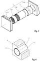
- Die Erfindung soll nachfolgend anhand von Ausführungsbeispielen mit Hilfe von Zeichnungen näher erläutert werden. Hierzu zeigen:
- Fig. 1
- ein Lüfter-Set, enthaltend ein Lüfterrohr, eine Simulationsblende und mehrere verschiedene Lüfterbauteile,
- Fig. 2
- eine Explosionsdarstellung einer Lüftereinheit, gebildet aus dem Lüfterrohr und den Lüfterbauteilen des Lüfter-Sets nach
Fig. 1 , - Fig. 3
- eine Explosionsdarstellung eines Simulators, gebildet aus dem Lüfterrohr und der Simulationsblende des Lüfter-Sets nach
Fig. 1 , - Fig. 4
- ein in eine Wand eingesetztes Lüfterrohr bzw. ein Wandeinbaumodul mit einem integrierten Lüfterrohr,
- Fig. 5
- ein erstes Ausführungsbeispiel einer Simulationsblende mit einer permanenten Öffnung als Blendenöffnung,
- Fig. 6
- ein zweites Ausführungsbeispiel einer Simulationsblende mit einer Sollöffnung als Blendenöffnung, gebildet durch eine Sollbruchlinie, in einem ersten und einem zweiten Zustand und
- Fig. 7
- ein drittes Ausführungsbeispiel einer Simulationsblende mit einer Sollöffnung als Blendenöffnung, gebildet durch eine temporäre Öffnung und einen Verschlussdeckel.
- Ein erfindungsgemäßes Lüfter-Set enthält, wie in
Fig. 1 dargestellt, ein Lüfterrohr 1.1, verschiedene Lüfterbauteile 1.2.x, wie z.B. einen Ventilator 1.2.1, einen Wärmespeicher 1.2.2, eine Innenblende 1.2.3 und eine Wetterschutzhaube 1.2.4, sowie eine Simulationsblende 0.1. Als Lüfterbauteile 1.2.x sollen sowohl Lüfterbauteile als auch Lüfterbaugruppen verstanden werden, die in das leere Lüfterrohr 1.1 eingesetzt oder an diesem angesetzt mit dem Lüfterrohr 1.1 eine funktionierende Lüftereinheit 1 bilden. Es ist dem Fachmann bekannt, um welche Lüfterbauteile 1.2.x es sich hier obligatorisch und optional handelt. - Das Lüfterrohr 1.1 wird mit den Lüfterbauteilen 1.2.x zu einer Lüftereinheit 1 komplettiert, wie in
Fig. 2 gezeigt. Alternativ wird, wie inFig. 3 gezeigt, das Lüfterrohr 1.1 mit der ein- oder angesetzten Simulationsblende 0.1 zu einem Simulator 0 komplettiert, der einen gleichen Strömungswiderstand aufweist, wie die Lüftereinheit 1. - Die Simulationsblende 0.1 weist eine Blendenöffnung auf, welche eine permanente Öffnung 2 oder eine Sollöffnung 3 im geöffneten Zustand ist. Abhängig von der Größe des Querschnittes der Blendenöffnung bildet die mit dem Lüfterrohr 1.1 verbundene Simulationsblende 0.1 einen Strömungswiderstand, der den Strömungswiderstand der alternativ eingesetzten Lüfterbauteile 1.2.x simuliert. Als Blendenöffnung soll auch eine Summe von Teilöffnungen verstanden werden. Die Summe der Größen der Querschnitte der Teilöffnungen bildet dann die Größe der Blendenöffnung. Zu unterschiedlich dimensionierten oder nicht baugleichen Lüftereinheiten 1 gehört entsprechend jeweils eine Simulationsblende 0.1 mit einer anderen Größe der Blendenöffnung, es sei denn die Größe der Blendenöffnung ist veränderbar.
- Durch die Simulation des Strömungswiderstandes der Lüftereinheit 1, der bevorzugt anhand vergegenständlichter Lüftereinheiten 1 gemessen wird und allein über die Größe der Blendenöffnung in der Simulationsblende 0.1 hergestellt wird, wird eine sehr einfache Lösung geschaffen, mit der die aus dem Stand der Technik bekannte A-Messung quasi bereits vor dem Einsetzen der Lüfterbauteile 1.2.x in die Lüfterrohre 1.1 der Lüftereinheit 1 durchgeführt werden kann, sobald die Lüfterrohre 1.1 in die Wände des Gebäudes bzw. Wandeinbaumodule 4 mit integriertem Lüfterrohr 1.1, wie in
Fig. 4 gezeigt, oder Wandeinbaumodule 4 mit einem rohrförmigen Durchbruch, der das Lüfterrohr 1.1 bildet, verbaut wurden. - Vor der Durchführung der Messungen wird die Simulationsblende 0.1 (in den Ausführungsbeispielen als Deckel ausgeführt) an eines von zwei Rohrenden 1.1.1 des Lüfterrohres 1.1 an- oder in das Lüfterrohr 1.1 dichtend eingesetzt. Die Blendenöffnung in der Simulationsblende 0.1 ist entweder eine permanente Öffnung 2 oder eine Sollöffnung 3, in einem geöffneten Zustand. Die Umfangsform der Blendenöffnung ist unerheblich. Auch kann insbesondere die permanente Öffnung 2, aber auch die Sollöffnung 3 durch mehrere Teilöffnungen bzw. Teilsollöffnungen gebildet sein, das heißt die permanente Öffnung 2 bzw. Sollöffnung 3 muss nicht in sich geschlossen sein.
- Wird die Simulationsblende 0.1 mit einer permanenten Öffnung 2 ausgeführt, wie als erstes Ausführungsbeispiel in
Fig. 5 dargestellt, kann sie nur für Messungen verwendet werden, die quasi einer A-Messung entsprechen. In diesem Falle würde man, sofern auch eine Messung durchgeführt werden soll, wie sie einleitend als B-Messung beschrieben wurde, das Lüfterrohr 1.1 unter Verwendung von herkömmlichen Mitteln abdichten. - Wird die Simulationsblende 0.1 mit einer Sollöffnung 3 ausgeführt, so kann diese in zwei Zuständen, gezeigt in den
Fig. 6 und 7 , verwendet werden. In einem ersten Zustand Z1, in dem die Sollöffnung 3 verschlossen ist, kann eine B-Messung, z. B. baubegleitend, durchgeführt werden. In einem zweiten Zustand Z2, in dem die Sollöffnung 3 geöffnet ist, kann quasi eine A-Messung durchgeführt werden, zur Gewinnung der Kenngrößen zur energetischen Berechnung und Bewertung des Gebäudes. - Für eine Simulationsblende 0.1 mit einer Sollöffnung 3 werden nachfolgend vorteilhafte Ausführungsbeispiele angegeben.
- Gemäß einem zweiten Ausführungsbeispiel ist die Simulationsblende 0.1 entlang einer den Umfang der Sollöffnung 3 beschreibenden Sollbruchlinie 3.1 geschwächt, wobei die Sollbruchlinie 3.1 z. B. eine die Simulationsblende 0.1 nicht vollständig durchdringende Perforationslinie ist. In
Fig. 6 ist eine solche Simulationsblende 0.1 in den beiden Zuständen Z1, Z2 gezeigt. Die Simulationsblende 0.1 wird durch Brechen der Sollbruchlinie 3.1 geöffnet, womit sie zum Abdichten des Lüfterrohres 1.1 zum Zwecke einer B-Messung nur einmal verwendbar ist. Ein solche Simulationsblende 0.1 kann auch durch eine robuste Folie gebildet werden, die z. B. um eines der zwei Rohrenden 1.1.1 gespannt oder geklebt wird. - Gemäß einem dritten Ausführungsbeispiel, dargestellt in
Fig. 7 , ist die Sollöffnung 3 in der Simulationsblende 0.1 durch eine temporäre Öffnung 3.2 und einen die temporäre Öffnung 3.2 freigebenden oder verschließenden Verschlussdeckel 3.3 gebildet, womit die Simulationsblende 0.1 mehrfach sowohl zum Abdichten als auch zum Simulieren verwendet werden kann. - Gemäß weiteren, in den Zeichnungen nicht dargestellten Ausführungsbeispielen wird die Sollöffnung 3 durch eine zu öffnende und vollständig schließbare Irisblende, einen verstellbaren Schieber oder einen Lochrevolver gebildet, womit die Simulationsblende 0.1 mehrfach und zur Simulation verschiedener, nicht baugleicher Lüftereinheiten 1 zum Abdichten und Simulieren verwendet werden kann.
- Auch kann die Simulationsblende 0.1 vorteilhaft aus einer Deckelplatte und einem darunter angeordneten Deckelrahmen gebildet sein, wobei die Blendenöffnung durch einen Spalt zwischen der Deckelplatte und dem Deckelrahmen, der an dem Lüfterrohr 1.1 angebracht werden kann, gebildet ist. Die Spaltbreite ist fest und somit zur Simulation genau einer Lüftereinheit 1 geeignet oder sie ist stufenweise verstellbar, womit sie über die Einstellung der verschiedenen Stufenabstände zur Simulation verschiedener nicht baugleicher Lüftereinheiten 1 geeignet ist.
- Ein Vorteil jeder der aufgezeigten Ausführungen der Simulationsblende 0.1 liegt darin, dass sie allein über die Auswahl der geometrischen Umfangsform, der Umfangsgröße und der Größe der Blendenöffnung zur Simulation des Strömungswiderstandes verschiedener nicht baugleicher bzw. nicht gleichdimensionierter Lüftereinheiten 1 herstellbar ist.
- Die Simulationsblende 0.1 kann bevorzugt aus einem Kunststoff hergestellt sein, der die Herstellung durch ein formgebendes Verfahren, welches für eine Massenproduktion geeignet ist, ermöglicht. Vorteilhaft kann sie einen oder mehrere Dichtringe oder Dichtlippen aufweisen, über die sie straff sitzend am Lüfterrohr 1.1 angebracht werden kann. Die Simulationsblende 0.1 kann dann für Messungen bei Unterdruck und bei Überdruck an einem gleichen Rohrende 1.1.1 angebracht sein. Nimmt man den Aufwand in Kauf, die Simulationsblende 0.1 für die Messung bei Überdruck bzw. Unterdruck jeweils an einem anderen Rohrende 1.1.1 zu positionieren, kann auf einen straffen und damit dichten Sitz der Simulationsblende 0.1 am Rohrende 1.1.1 verzichtet werden. Die Simulationsblende 0.1 wird dann jeweils so positioniert, dass der auf die Simulationsblende 0.1 in Richtung des Lüfterrohres 1 wirkende Druck immer ein Überdruck ist, mit dem die Simulationsblende 0.1 kraftschlüssig an dem Rohrende 1.1.1 dicht anliegt.
-
- 0
- Simulator
- 0.1
- Simulationsblende
- 1
- Lüftereinheit
- 1.1
- Lüfterrohr
- 1.1.1
- Rohrende des Lüfterrohres 1.1
- 1.2.x
- Lüfterbauteile
- 1.2.1 Ventilator
- 1.2.2 Wärmespeicher
- 1.2.3 Innenblende
- 1.2.4 Wetterschutzhaube
- 2
- permanente Öffnung
- 3
- Sollöffnung
- 3.1
- Sollbruchlinie
- 3.2
- temporäre Öffnung
- 3.3
- Verschlussdeckel
- 4
- Wandeinbaumodul
- Z1
- erster Zustand der Simulationsblende 0.1
- Z2
- zweiter Zustand der Simulationsblende 0.1
Claims (10)
- Lüfter-Set, enthaltend ein Lüfterrohr (1.1), mehrere Lüfterbauteile (1.2.x), die in das leere Lüfterrohr (1.1) eingesetzt oder an dem Lüfterrohr (1.1) angesetzt werden können, um mit dem Lüfterrohr (1.1) eine Lüftereinheit (1) zu bilden, und eine Simulationsblende (0.1) mit einer Blendenöffnung, die alternativ in das leere Lüfterrohr (1.1) eingesetzt oder an dem Lüfterrohr (1.1) angesetzt werden kann, um mit dem Lüfterrohr (1.1) einen Simulator (0) zu bilden, wobei ein so gebildeter Simulator (0) einen gleichen Strömungswiderstand für eine hindurchtretende Strömung aufweist, wie eine so gebildete Lüftereinheit (1).
- Lüfter-Set nach Anspruch 1, dadurch gekennzeichnet,
dass die Blendenöffnung der Simulationsblende (0.1) eine permanente Öffnung (2) ist. - Lüfter-Set nach Anspruch 1, dadurch gekennzeichnet,
dass die Blendenöffnung der Simulationsblende (0.1) eine in einem zweiten Zustand (Z2) der Simulationsblende (0.1) geöffnete Sollöffnung (3) ist, die in einem ersten Zustand (Z1) der Simulationsblende (0.1) geschlossen ist, sodass die Simulationsblende (0.1) außer zur Simulation auch zum Abdichten des Lüfterrohres (1.1) verwendet werden kann. - Lüfter-Set nach Anspruch 3, dadurch gekennzeichnet,
dass die Sollöffnung (3) durch eine den Umfang der Sollöffnung (3) beschreibende Sollbruchlinie (3.1) gebildet ist, die durch Brechen geöffnet werden kann, womit die Simulationsblende (0.1) zum Abdichten nur einmal verwendbar ist. - Lüfter-Set nach Anspruch 3, dadurch gekennzeichnet,
dass die Sollöffnung (3) durch eine temporäre Öffnung (3.2) und einen Verschlussdeckel (3.3) gebildet ist, womit die Simulationsblende (0.1) mehrfach zum Abdichten und zum Simulieren verwendet werden kann. - Lüfter-Set nach Anspruch 1, dadurch gekennzeichnet,
dass die Blendenöffnung der Simulationsblende (0.1) durch eine in ihrer Größe verstellbare Öffnungsblende oder einen Lochrevolver gebildet ist, womit die Simulationsblende (0.1) auch zum Simulieren anderer nicht baugleicher oder verschieden dimensionierter Lüftereinheiten (1) gemäß Anspruch 1 verwendet werden kann. - Lüfter-Set nach Anspruch 1, dadurch gekennzeichnet,
dass es zusätzlich ein Wandeinbaumodul (4) enthält, in dem das Lüfterrohr (1.1) integrierbar oder integriert ist. - Lüfter-Set nach Anspruch 1, dadurch gekennzeichnet,
dass das Lüfterrohr (1.1) ein rohrförmiger Durchbruch in einem Wandeinbaumodul (4) ist. - Verwendung eines Lüfter-Sets nach einem der Ansprüche 1 bis 8 zur alternativen Bildung der Lüftereinheit (1), aus dem Lüfterrohr (1.1) und den Lüfterbauteilen (1.2.x), oder des Simulators (0), aus dem Lüfterrohr (1.1) und der Simulationsblende (0.1).
- Verfahren zur Dichtheitsmessung eines Gebäudes in verschiedenen Bauzuständen, bei dem im dem Gebäude über eine vorgegebene Zeit ein vorgegebener Überdruck oder Unterdruck erzeugt wird, der sich dabei einstellende Luftvolumenstrom aus dem Gebäude oder in das Gebäude gemessen wird und aus dem gemessenen Luftvolumenstrom ein Dichtheitswert für das Gebäude in dem jeweiligen Bauzustand abgeleitet wird,
dadurch gekennzeichnet,
dass in dem Gebäude eingebaute Lüfterrohre (1.1), bevor sie jeweils mit Lüfterbauteilen (1.2.x) zu einer Lüftereinheit (1) komplettiert werden, vorübergehend mit einer Simulationsblende (0.1) zu einem Simulator (0) komplettiert werden, der einen gleichen Strömungswiderstand für einen hindurchtretenden Luftvolumenstrom aufweist, wie die Lüftereinheit (1), womit in verschiedenen Bauzuständen, in denen eine Dichtheitsmessung durchgeführt wird, der durch die Lüfterrohre (1.1) hindurchtretende Luftvolumenstrom gleich ist.
Applications Claiming Priority (1)
| Application Number | Priority Date | Filing Date | Title |
|---|---|---|---|
| DE102018110262 | 2018-04-27 |
Publications (2)
| Publication Number | Publication Date |
|---|---|
| EP3561404A1 true EP3561404A1 (de) | 2019-10-30 |
| EP3561404B1 EP3561404B1 (de) | 2021-11-17 |
Family
ID=66217813
Family Applications (1)
| Application Number | Title | Priority Date | Filing Date |
|---|---|---|---|
| EP19169599.8A Active EP3561404B1 (de) | 2018-04-27 | 2019-04-16 | Lüfter-set mit einem lüfterrohr, mehreren lüfterbauteilen und einer simulationsblende und verfahren zur dichtheitsmessung eines gebäudes |
Country Status (2)
| Country | Link |
|---|---|
| EP (1) | EP3561404B1 (de) |
| DE (1) | DE102019110058A1 (de) |
Cited By (1)
| Publication number | Priority date | Publication date | Assignee | Title |
|---|---|---|---|---|
| CN114997082A (zh) * | 2022-06-02 | 2022-09-02 | 西北工业大学 | 一种金属海绵离心通风器阻力快速预测方法 |
Families Citing this family (1)
| Publication number | Priority date | Publication date | Assignee | Title |
|---|---|---|---|---|
| DE102022102824B3 (de) | 2022-02-07 | 2023-06-22 | Deutsches Zentrum für Luft- und Raumfahrt e.V. | Verfahren zur Bestimmung von Leckagen in Gebäudehüllen |
Citations (3)
| Publication number | Priority date | Publication date | Assignee | Title |
|---|---|---|---|---|
| GB2189023A (en) * | 1986-04-11 | 1987-10-14 | Hunter Int Ltd | Mounting a ventilator fan in a wall |
| WO2002004912A1 (fr) * | 2000-07-12 | 2002-01-17 | Aldes Aeraulique | Procede de mesure de l'etancheite a l'air d'un bâtiment et du reseau de ventilation mecanique de celui-ci et dispositif pour la mise en oeuvre de ce procede |
| WO2016129997A1 (en) * | 2015-02-09 | 2016-08-18 | Nederlandse Organisatie Voor Toegepast-Natuurwetenschappelijk Onderzoek Tno | Method and system for testing airtightness of a building envelope |
-
2019
- 2019-04-16 DE DE102019110058.5A patent/DE102019110058A1/de not_active Withdrawn
- 2019-04-16 EP EP19169599.8A patent/EP3561404B1/de active Active
Patent Citations (3)
| Publication number | Priority date | Publication date | Assignee | Title |
|---|---|---|---|---|
| GB2189023A (en) * | 1986-04-11 | 1987-10-14 | Hunter Int Ltd | Mounting a ventilator fan in a wall |
| WO2002004912A1 (fr) * | 2000-07-12 | 2002-01-17 | Aldes Aeraulique | Procede de mesure de l'etancheite a l'air d'un bâtiment et du reseau de ventilation mecanique de celui-ci et dispositif pour la mise en oeuvre de ce procede |
| WO2016129997A1 (en) * | 2015-02-09 | 2016-08-18 | Nederlandse Organisatie Voor Toegepast-Natuurwetenschappelijk Onderzoek Tno | Method and system for testing airtightness of a building envelope |
Non-Patent Citations (1)
| Title |
|---|
| "Thermal performance of buildings - determination of air permeability of buildings - fan pressuriztion method.", ISO 9972, 1 May 2006 (2006-05-01), XP055203280, Retrieved from the Internet <URL:http://mosenergoconsult.ru/wp-content/uploads/2014/01/ISO-9972-2006-EN.pdf> [retrieved on 20150717] * |
Cited By (1)
| Publication number | Priority date | Publication date | Assignee | Title |
|---|---|---|---|---|
| CN114997082A (zh) * | 2022-06-02 | 2022-09-02 | 西北工业大学 | 一种金属海绵离心通风器阻力快速预测方法 |
Also Published As
| Publication number | Publication date |
|---|---|
| EP3561404B1 (de) | 2021-11-17 |
| DE102019110058A1 (de) | 2019-10-31 |
Similar Documents
| Publication | Publication Date | Title |
|---|---|---|
| DE19548108B4 (de) | Vorrichtung und Verfahren, um plötzliche Druckänderungen in Fahrzeugen, insbesondere Bodenfahrzeugen, zu vermeiden | |
| DE3106191A1 (de) | Verfahren und vorrichtung zum feststellen undichter stellen in einem bauwerk | |
| EP3561404B1 (de) | Lüfter-set mit einem lüfterrohr, mehreren lüfterbauteilen und einer simulationsblende und verfahren zur dichtheitsmessung eines gebäudes | |
| WO2016041893A1 (de) | Folienkammer mit messvolumen zur grobleckerkennung | |
| WO2008009333A1 (de) | Messanordnung zur strömungsmessung in einem kanal | |
| EP0506013A2 (de) | Vorrichtung zum Prüfen von Rohrleitungen | |
| DE2932280A1 (de) | Vorrichtung und verfahren zum abdruecken von rohrleitungen | |
| DE102017120272B4 (de) | Verfahren zum Detektieren einer Leckage an einem Vakuumaufbau und Vorrichtung zur Herstellung eines Faserverbundbauteils | |
| EP2520920B1 (de) | Prüfvorrichtung zur Prüfung der Dichtigkeit eines hochwasserdichten Fensters | |
| DE102005003924B4 (de) | Verfahren zur Ansteuerung eines Tankentlüftungsventils eines Kraftfahrzeuges während einer Dichtigkeitsprüfung | |
| DE202018102529U1 (de) | Rohrverschluss zur Simulation eines Ströumungswiderstandes einer Lüfterbaugruppe | |
| DE10131752A1 (de) | Anordnung und Verfahren zur Messung der Gasdurchlässigkeit eines porösen Baustoffes | |
| WO2017013098A1 (de) | Extrudierter dichtungsstrang mit entlüftungsöffnungen | |
| DE102013201025B4 (de) | Vorrichtung zum Bestimmen der Größe eines Volumenstroms eines Fluids | |
| DE102008022602A1 (de) | Kanalsystem mit Prüfvorrichtung | |
| EP1628087B1 (de) | Verfahren und Einrichtung zum Ermitteln einer Dichtheit eines Raums | |
| DE102019101780A1 (de) | Wasserzählermodul und Wasserzählermodulinstallation | |
| DE102019103441A1 (de) | Verfahren zur Kalibrierung einer PIV Messanordnung | |
| DE102005060743B4 (de) | Vorrichtung zur Bestimmung der Dichtigkeit eines Bauwerks | |
| DE3800486A1 (de) | Druckaufnehmer zur erfassung eines bewetterungsstromes einschliesslich einer luttenleitung und eines messverfahrens | |
| DE102017215394A1 (de) | Vorrichtung zur Messung und/oder Erfassung eines Schäumungsverhaltens eines Schaums | |
| DE102022203545B4 (de) | Fahrzeug zur Personenbeförderung mit Druckschutzeinrichtung | |
| DE202015101092U1 (de) | Volumenstromregleranordnung | |
| DE19612996C2 (de) | Meßgerät zur Überwachung der Strömung eines Fluids | |
| EP0542041B1 (de) | Einrichtung und Verfahren zum Überwachen von zwei voneinander beabstandeten Abdichtungen |
Legal Events
| Date | Code | Title | Description |
|---|---|---|---|
| PUAI | Public reference made under article 153(3) epc to a published international application that has entered the european phase |
Free format text: ORIGINAL CODE: 0009012 |
|
| STAA | Information on the status of an ep patent application or granted ep patent |
Free format text: STATUS: THE APPLICATION HAS BEEN PUBLISHED |
|
| AK | Designated contracting states |
Kind code of ref document: A1 Designated state(s): AL AT BE BG CH CY CZ DE DK EE ES FI FR GB GR HR HU IE IS IT LI LT LU LV MC MK MT NL NO PL PT RO RS SE SI SK SM TR |
|
| AX | Request for extension of the european patent |
Extension state: BA ME |
|
| STAA | Information on the status of an ep patent application or granted ep patent |
Free format text: STATUS: REQUEST FOR EXAMINATION WAS MADE |
|
| 17P | Request for examination filed |
Effective date: 20200428 |
|
| RBV | Designated contracting states (corrected) |
Designated state(s): AL AT BE BG CH CY CZ DE DK EE ES FI FR GB GR HR HU IE IS IT LI LT LU LV MC MK MT NL NO PL PT RO RS SE SI SK SM TR |
|
| GRAP | Despatch of communication of intention to grant a patent |
Free format text: ORIGINAL CODE: EPIDOSNIGR1 |
|
| STAA | Information on the status of an ep patent application or granted ep patent |
Free format text: STATUS: GRANT OF PATENT IS INTENDED |
|
| RIC1 | Information provided on ipc code assigned before grant |
Ipc: F24F 7/00 20210101AFI20210517BHEP Ipc: F24F 13/02 20060101ALI20210517BHEP Ipc: G01M 3/26 20060101ALI20210517BHEP Ipc: G01M 3/32 20060101ALI20210517BHEP Ipc: F24F 7/013 20060101ALI20210517BHEP |
|
| INTG | Intention to grant announced |
Effective date: 20210611 |
|
| GRAS | Grant fee paid |
Free format text: ORIGINAL CODE: EPIDOSNIGR3 |
|
| GRAA | (expected) grant |
Free format text: ORIGINAL CODE: 0009210 |
|
| STAA | Information on the status of an ep patent application or granted ep patent |
Free format text: STATUS: THE PATENT HAS BEEN GRANTED |
|
| AK | Designated contracting states |
Kind code of ref document: B1 Designated state(s): AL AT BE BG CH CY CZ DE DK EE ES FI FR GB GR HR HU IE IS IT LI LT LU LV MC MK MT NL NO PL PT RO RS SE SI SK SM TR |
|
| REG | Reference to a national code |
Ref country code: GB Ref legal event code: FG4D Free format text: NOT ENGLISH |
|
| REG | Reference to a national code |
Ref country code: IE Ref legal event code: FG4D Free format text: LANGUAGE OF EP DOCUMENT: GERMAN |
|
| REG | Reference to a national code |
Ref country code: DE Ref legal event code: R096 Ref document number: 502019002752 Country of ref document: DE |
|
| REG | Reference to a national code |
Ref country code: AT Ref legal event code: REF Ref document number: 1448366 Country of ref document: AT Kind code of ref document: T Effective date: 20211215 |
|
| REG | Reference to a national code |
Ref country code: LT Ref legal event code: MG9D |
|
| REG | Reference to a national code |
Ref country code: NL Ref legal event code: MP Effective date: 20211117 |
|
| PG25 | Lapsed in a contracting state [announced via postgrant information from national office to epo] |
Ref country code: RS Free format text: LAPSE BECAUSE OF FAILURE TO SUBMIT A TRANSLATION OF THE DESCRIPTION OR TO PAY THE FEE WITHIN THE PRESCRIBED TIME-LIMIT Effective date: 20211117 Ref country code: LT Free format text: LAPSE BECAUSE OF FAILURE TO SUBMIT A TRANSLATION OF THE DESCRIPTION OR TO PAY THE FEE WITHIN THE PRESCRIBED TIME-LIMIT Effective date: 20211117 Ref country code: FI Free format text: LAPSE BECAUSE OF FAILURE TO SUBMIT A TRANSLATION OF THE DESCRIPTION OR TO PAY THE FEE WITHIN THE PRESCRIBED TIME-LIMIT Effective date: 20211117 Ref country code: BG Free format text: LAPSE BECAUSE OF FAILURE TO SUBMIT A TRANSLATION OF THE DESCRIPTION OR TO PAY THE FEE WITHIN THE PRESCRIBED TIME-LIMIT Effective date: 20220217 |
|
| PG25 | Lapsed in a contracting state [announced via postgrant information from national office to epo] |
Ref country code: IS Free format text: LAPSE BECAUSE OF FAILURE TO SUBMIT A TRANSLATION OF THE DESCRIPTION OR TO PAY THE FEE WITHIN THE PRESCRIBED TIME-LIMIT Effective date: 20220317 Ref country code: SE Free format text: LAPSE BECAUSE OF FAILURE TO SUBMIT A TRANSLATION OF THE DESCRIPTION OR TO PAY THE FEE WITHIN THE PRESCRIBED TIME-LIMIT Effective date: 20211117 Ref country code: PT Free format text: LAPSE BECAUSE OF FAILURE TO SUBMIT A TRANSLATION OF THE DESCRIPTION OR TO PAY THE FEE WITHIN THE PRESCRIBED TIME-LIMIT Effective date: 20220317 Ref country code: PL Free format text: LAPSE BECAUSE OF FAILURE TO SUBMIT A TRANSLATION OF THE DESCRIPTION OR TO PAY THE FEE WITHIN THE PRESCRIBED TIME-LIMIT Effective date: 20211117 Ref country code: NO Free format text: LAPSE BECAUSE OF FAILURE TO SUBMIT A TRANSLATION OF THE DESCRIPTION OR TO PAY THE FEE WITHIN THE PRESCRIBED TIME-LIMIT Effective date: 20220217 Ref country code: NL Free format text: LAPSE BECAUSE OF FAILURE TO SUBMIT A TRANSLATION OF THE DESCRIPTION OR TO PAY THE FEE WITHIN THE PRESCRIBED TIME-LIMIT Effective date: 20211117 Ref country code: LV Free format text: LAPSE BECAUSE OF FAILURE TO SUBMIT A TRANSLATION OF THE DESCRIPTION OR TO PAY THE FEE WITHIN THE PRESCRIBED TIME-LIMIT Effective date: 20211117 Ref country code: HR Free format text: LAPSE BECAUSE OF FAILURE TO SUBMIT A TRANSLATION OF THE DESCRIPTION OR TO PAY THE FEE WITHIN THE PRESCRIBED TIME-LIMIT Effective date: 20211117 Ref country code: GR Free format text: LAPSE BECAUSE OF FAILURE TO SUBMIT A TRANSLATION OF THE DESCRIPTION OR TO PAY THE FEE WITHIN THE PRESCRIBED TIME-LIMIT Effective date: 20220218 Ref country code: ES Free format text: LAPSE BECAUSE OF FAILURE TO SUBMIT A TRANSLATION OF THE DESCRIPTION OR TO PAY THE FEE WITHIN THE PRESCRIBED TIME-LIMIT Effective date: 20211117 |
|
| PG25 | Lapsed in a contracting state [announced via postgrant information from national office to epo] |
Ref country code: SM Free format text: LAPSE BECAUSE OF FAILURE TO SUBMIT A TRANSLATION OF THE DESCRIPTION OR TO PAY THE FEE WITHIN THE PRESCRIBED TIME-LIMIT Effective date: 20211117 Ref country code: SK Free format text: LAPSE BECAUSE OF FAILURE TO SUBMIT A TRANSLATION OF THE DESCRIPTION OR TO PAY THE FEE WITHIN THE PRESCRIBED TIME-LIMIT Effective date: 20211117 Ref country code: RO Free format text: LAPSE BECAUSE OF FAILURE TO SUBMIT A TRANSLATION OF THE DESCRIPTION OR TO PAY THE FEE WITHIN THE PRESCRIBED TIME-LIMIT Effective date: 20211117 Ref country code: EE Free format text: LAPSE BECAUSE OF FAILURE TO SUBMIT A TRANSLATION OF THE DESCRIPTION OR TO PAY THE FEE WITHIN THE PRESCRIBED TIME-LIMIT Effective date: 20211117 Ref country code: DK Free format text: LAPSE BECAUSE OF FAILURE TO SUBMIT A TRANSLATION OF THE DESCRIPTION OR TO PAY THE FEE WITHIN THE PRESCRIBED TIME-LIMIT Effective date: 20211117 Ref country code: CZ Free format text: LAPSE BECAUSE OF FAILURE TO SUBMIT A TRANSLATION OF THE DESCRIPTION OR TO PAY THE FEE WITHIN THE PRESCRIBED TIME-LIMIT Effective date: 20211117 |
|
| REG | Reference to a national code |
Ref country code: DE Ref legal event code: R097 Ref document number: 502019002752 Country of ref document: DE |
|
| PLBE | No opposition filed within time limit |
Free format text: ORIGINAL CODE: 0009261 |
|
| STAA | Information on the status of an ep patent application or granted ep patent |
Free format text: STATUS: NO OPPOSITION FILED WITHIN TIME LIMIT |
|
| 26N | No opposition filed |
Effective date: 20220818 |
|
| PG25 | Lapsed in a contracting state [announced via postgrant information from national office to epo] |
Ref country code: AL Free format text: LAPSE BECAUSE OF FAILURE TO SUBMIT A TRANSLATION OF THE DESCRIPTION OR TO PAY THE FEE WITHIN THE PRESCRIBED TIME-LIMIT Effective date: 20211117 |
|
| PG25 | Lapsed in a contracting state [announced via postgrant information from national office to epo] |
Ref country code: SI Free format text: LAPSE BECAUSE OF FAILURE TO SUBMIT A TRANSLATION OF THE DESCRIPTION OR TO PAY THE FEE WITHIN THE PRESCRIBED TIME-LIMIT Effective date: 20211117 |
|
| REG | Reference to a national code |
Ref country code: CH Ref legal event code: PL |
|
| REG | Reference to a national code |
Ref country code: BE Ref legal event code: MM Effective date: 20220430 |
|
| PG25 | Lapsed in a contracting state [announced via postgrant information from national office to epo] |
Ref country code: MC Free format text: LAPSE BECAUSE OF FAILURE TO SUBMIT A TRANSLATION OF THE DESCRIPTION OR TO PAY THE FEE WITHIN THE PRESCRIBED TIME-LIMIT Effective date: 20211117 Ref country code: LU Free format text: LAPSE BECAUSE OF NON-PAYMENT OF DUE FEES Effective date: 20220416 Ref country code: LI Free format text: LAPSE BECAUSE OF NON-PAYMENT OF DUE FEES Effective date: 20220430 Ref country code: CH Free format text: LAPSE BECAUSE OF NON-PAYMENT OF DUE FEES Effective date: 20220430 |
|
| PG25 | Lapsed in a contracting state [announced via postgrant information from national office to epo] |
Ref country code: BE Free format text: LAPSE BECAUSE OF NON-PAYMENT OF DUE FEES Effective date: 20220430 |
|
| PG25 | Lapsed in a contracting state [announced via postgrant information from national office to epo] |
Ref country code: IT Free format text: LAPSE BECAUSE OF FAILURE TO SUBMIT A TRANSLATION OF THE DESCRIPTION OR TO PAY THE FEE WITHIN THE PRESCRIBED TIME-LIMIT Effective date: 20211117 |
|
| PGFP | Annual fee paid to national office [announced via postgrant information from national office to epo] |
Ref country code: IE Payment date: 20230419 Year of fee payment: 5 Ref country code: FR Payment date: 20230424 Year of fee payment: 5 |
|
| REG | Reference to a national code |
Ref country code: DE Ref legal event code: R082 Ref document number: 502019002752 Country of ref document: DE Representative=s name: GLEIM PETRI PATENT- UND RECHTSANWALTSPARTNERSC, DE |
|
| GBPC | Gb: european patent ceased through non-payment of renewal fee |
Effective date: 20230416 |
|
| PG25 | Lapsed in a contracting state [announced via postgrant information from national office to epo] |
Ref country code: GB Free format text: LAPSE BECAUSE OF NON-PAYMENT OF DUE FEES Effective date: 20230416 |
|
| PG25 | Lapsed in a contracting state [announced via postgrant information from national office to epo] |
Ref country code: GB Free format text: LAPSE BECAUSE OF NON-PAYMENT OF DUE FEES Effective date: 20230416 |
|
| REG | Reference to a national code |
Ref country code: DE Ref legal event code: R082 Ref document number: 502019002752 Country of ref document: DE |
|
| REG | Reference to a national code |
Ref country code: DE Ref legal event code: R084 Ref document number: 502019002752 Country of ref document: DE |
|
| PG25 | Lapsed in a contracting state [announced via postgrant information from national office to epo] |
Ref country code: HU Free format text: LAPSE BECAUSE OF FAILURE TO SUBMIT A TRANSLATION OF THE DESCRIPTION OR TO PAY THE FEE WITHIN THE PRESCRIBED TIME-LIMIT; INVALID AB INITIO Effective date: 20190416 |
|
| PG25 | Lapsed in a contracting state [announced via postgrant information from national office to epo] |
Ref country code: MK Free format text: LAPSE BECAUSE OF FAILURE TO SUBMIT A TRANSLATION OF THE DESCRIPTION OR TO PAY THE FEE WITHIN THE PRESCRIBED TIME-LIMIT Effective date: 20211117 Ref country code: CY Free format text: LAPSE BECAUSE OF FAILURE TO SUBMIT A TRANSLATION OF THE DESCRIPTION OR TO PAY THE FEE WITHIN THE PRESCRIBED TIME-LIMIT Effective date: 20211117 |
|
| PG25 | Lapsed in a contracting state [announced via postgrant information from national office to epo] |
Ref country code: MT Free format text: LAPSE BECAUSE OF FAILURE TO SUBMIT A TRANSLATION OF THE DESCRIPTION OR TO PAY THE FEE WITHIN THE PRESCRIBED TIME-LIMIT Effective date: 20211117 |
|
| PG25 | Lapsed in a contracting state [announced via postgrant information from national office to epo] |
Ref country code: FR Free format text: LAPSE BECAUSE OF NON-PAYMENT OF DUE FEES Effective date: 20240430 |
|
| PG25 | Lapsed in a contracting state [announced via postgrant information from national office to epo] |
Ref country code: FR Free format text: LAPSE BECAUSE OF NON-PAYMENT OF DUE FEES Effective date: 20240430 |
|
| PG25 | Lapsed in a contracting state [announced via postgrant information from national office to epo] |
Ref country code: IE Free format text: LAPSE BECAUSE OF NON-PAYMENT OF DUE FEES Effective date: 20240416 |
|
| REG | Reference to a national code |
Ref country code: AT Ref legal event code: MM01 Ref document number: 1448366 Country of ref document: AT Kind code of ref document: T Effective date: 20240416 |
|
| PG25 | Lapsed in a contracting state [announced via postgrant information from national office to epo] |
Ref country code: AT Free format text: LAPSE BECAUSE OF NON-PAYMENT OF DUE FEES Effective date: 20240416 |
|
| PGFP | Annual fee paid to national office [announced via postgrant information from national office to epo] |
Ref country code: DE Payment date: 20250303 Year of fee payment: 7 |
|
| PG25 | Lapsed in a contracting state [announced via postgrant information from national office to epo] |
Ref country code: TR Free format text: LAPSE BECAUSE OF FAILURE TO SUBMIT A TRANSLATION OF THE DESCRIPTION OR TO PAY THE FEE WITHIN THE PRESCRIBED TIME-LIMIT Effective date: 20211117 |
|
| PGFP | Annual fee paid to national office [announced via postgrant information from national office to epo] |
Ref country code: AT Payment date: 20260410 Year of fee payment: 5 |