EP3561322B1 - Befestigungssystem zum befestigen von einbauelementen in einer kabine eines fahrzeugs - Google Patents
Befestigungssystem zum befestigen von einbauelementen in einer kabine eines fahrzeugs Download PDFInfo
- Publication number
- EP3561322B1 EP3561322B1 EP19168296.2A EP19168296A EP3561322B1 EP 3561322 B1 EP3561322 B1 EP 3561322B1 EP 19168296 A EP19168296 A EP 19168296A EP 3561322 B1 EP3561322 B1 EP 3561322B1
- Authority
- EP
- European Patent Office
- Prior art keywords
- fastening
- ball
- opening
- interior
- fastening system
- Prior art date
- Legal status (The legal status is an assumption and is not a legal conclusion. Google has not performed a legal analysis and makes no representation as to the accuracy of the status listed.)
- Active
Links
Images

Classifications
-
- B—PERFORMING OPERATIONS; TRANSPORTING
- B64—AIRCRAFT; AVIATION; COSMONAUTICS
- B64D—EQUIPMENT FOR FITTING IN OR TO AIRCRAFT; FLIGHT SUITS; PARACHUTES; ARRANGEMENT OR MOUNTING OF POWER PLANTS OR PROPULSION TRANSMISSIONS IN AIRCRAFT
- B64D11/00—Passenger or crew accommodation; Flight-deck installations not otherwise provided for
- B64D11/06—Arrangements of seats, or adaptations or details specially adapted for aircraft seats
- B64D11/0696—Means for fastening seats to floors, e.g. to floor rails
-
- B—PERFORMING OPERATIONS; TRANSPORTING
- B60—VEHICLES IN GENERAL
- B60N—SEATS SPECIALLY ADAPTED FOR VEHICLES; VEHICLE PASSENGER ACCOMMODATION NOT OTHERWISE PROVIDED FOR
- B60N2/00—Seats specially adapted for vehicles; Arrangement or mounting of seats in vehicles
- B60N2/005—Arrangement or mounting of seats in vehicles, e.g. dismountable auxiliary seats
- B60N2/015—Attaching seats directly to vehicle chassis
- B60N2/01508—Attaching seats directly to vehicle chassis using quick release attachments
- B60N2/01516—Attaching seats directly to vehicle chassis using quick release attachments with locking mechanisms
-
- B—PERFORMING OPERATIONS; TRANSPORTING
- B64—AIRCRAFT; AVIATION; COSMONAUTICS
- B64C—AEROPLANES; HELICOPTERS
- B64C1/00—Fuselages; Constructional features common to fuselages, wings, stabilising surfaces or the like
-
- B—PERFORMING OPERATIONS; TRANSPORTING
- B64—AIRCRAFT; AVIATION; COSMONAUTICS
- B64C—AEROPLANES; HELICOPTERS
- B64C1/00—Fuselages; Constructional features common to fuselages, wings, stabilising surfaces or the like
- B64C1/06—Frames; Stringers; Longerons ; Fuselage sections
- B64C1/066—Interior liners
-
- B—PERFORMING OPERATIONS; TRANSPORTING
- B64—AIRCRAFT; AVIATION; COSMONAUTICS
- B64C—AEROPLANES; HELICOPTERS
- B64C1/00—Fuselages; Constructional features common to fuselages, wings, stabilising surfaces or the like
- B64C1/18—Floors
-
- B—PERFORMING OPERATIONS; TRANSPORTING
- B64—AIRCRAFT; AVIATION; COSMONAUTICS
- B64F—GROUND OR AIRCRAFT-CARRIER-DECK INSTALLATIONS SPECIALLY ADAPTED FOR USE IN CONNECTION WITH AIRCRAFT; DESIGNING, MANUFACTURING, ASSEMBLING, CLEANING, MAINTAINING OR REPAIRING AIRCRAFT, NOT OTHERWISE PROVIDED FOR; HANDLING, TRANSPORTING, TESTING OR INSPECTING AIRCRAFT COMPONENTS, NOT OTHERWISE PROVIDED FOR
- B64F5/00—Designing, manufacturing, assembling, cleaning, maintaining or repairing aircraft, not otherwise provided for; Handling, transporting, testing or inspecting aircraft components, not otherwise provided for
- B64F5/10—Manufacturing or assembling aircraft, e.g. jigs therefor
-
- F—MECHANICAL ENGINEERING; LIGHTING; HEATING; WEAPONS; BLASTING
- F16—ENGINEERING ELEMENTS AND UNITS; GENERAL MEASURES FOR PRODUCING AND MAINTAINING EFFECTIVE FUNCTIONING OF MACHINES OR INSTALLATIONS; THERMAL INSULATION IN GENERAL
- F16B—DEVICES FOR FASTENING OR SECURING CONSTRUCTIONAL ELEMENTS OR MACHINE PARTS TOGETHER, e.g. NAILS, BOLTS, CIRCLIPS, CLAMPS, CLIPS OR WEDGES; JOINTS OR JOINTING
- F16B37/00—Nuts or like thread-engaging members
-
- F—MECHANICAL ENGINEERING; LIGHTING; HEATING; WEAPONS; BLASTING
- F16—ENGINEERING ELEMENTS AND UNITS; GENERAL MEASURES FOR PRODUCING AND MAINTAINING EFFECTIVE FUNCTIONING OF MACHINES OR INSTALLATIONS; THERMAL INSULATION IN GENERAL
- F16C—SHAFTS; FLEXIBLE SHAFTS; ELEMENTS OR CRANKSHAFT MECHANISMS; ROTARY BODIES OTHER THAN GEARING ELEMENTS; BEARINGS
- F16C11/00—Pivots; Pivotal connections
- F16C11/04—Pivotal connections
- F16C11/06—Ball-joints; Other joints having more than one degree of angular freedom, i.e. universal joints
- F16C11/0604—Construction of the male part
-
- F—MECHANICAL ENGINEERING; LIGHTING; HEATING; WEAPONS; BLASTING
- F16—ENGINEERING ELEMENTS AND UNITS; GENERAL MEASURES FOR PRODUCING AND MAINTAINING EFFECTIVE FUNCTIONING OF MACHINES OR INSTALLATIONS; THERMAL INSULATION IN GENERAL
- F16C—SHAFTS; FLEXIBLE SHAFTS; ELEMENTS OR CRANKSHAFT MECHANISMS; ROTARY BODIES OTHER THAN GEARING ELEMENTS; BEARINGS
- F16C11/00—Pivots; Pivotal connections
- F16C11/04—Pivotal connections
- F16C11/06—Ball-joints; Other joints having more than one degree of angular freedom, i.e. universal joints
- F16C11/0604—Construction of the male part
- F16C11/0609—Construction of the male part made from two or more parts
-
- F—MECHANICAL ENGINEERING; LIGHTING; HEATING; WEAPONS; BLASTING
- F16—ENGINEERING ELEMENTS AND UNITS; GENERAL MEASURES FOR PRODUCING AND MAINTAINING EFFECTIVE FUNCTIONING OF MACHINES OR INSTALLATIONS; THERMAL INSULATION IN GENERAL
- F16C—SHAFTS; FLEXIBLE SHAFTS; ELEMENTS OR CRANKSHAFT MECHANISMS; ROTARY BODIES OTHER THAN GEARING ELEMENTS; BEARINGS
- F16C11/00—Pivots; Pivotal connections
- F16C11/04—Pivotal connections
- F16C11/06—Ball-joints; Other joints having more than one degree of angular freedom, i.e. universal joints
- F16C11/0619—Ball-joints; Other joints having more than one degree of angular freedom, i.e. universal joints the female part comprising a blind socket receiving the male part
- F16C11/0623—Construction or details of the socket member
-
- F—MECHANICAL ENGINEERING; LIGHTING; HEATING; WEAPONS; BLASTING
- F16—ENGINEERING ELEMENTS AND UNITS; GENERAL MEASURES FOR PRODUCING AND MAINTAINING EFFECTIVE FUNCTIONING OF MACHINES OR INSTALLATIONS; THERMAL INSULATION IN GENERAL
- F16C—SHAFTS; FLEXIBLE SHAFTS; ELEMENTS OR CRANKSHAFT MECHANISMS; ROTARY BODIES OTHER THAN GEARING ELEMENTS; BEARINGS
- F16C11/00—Pivots; Pivotal connections
- F16C11/04—Pivotal connections
- F16C11/06—Ball-joints; Other joints having more than one degree of angular freedom, i.e. universal joints
- F16C11/0619—Ball-joints; Other joints having more than one degree of angular freedom, i.e. universal joints the female part comprising a blind socket receiving the male part
- F16C11/0623—Construction or details of the socket member
- F16C11/0642—Special features of the plug or cover on the blind end of the socket
-
- F—MECHANICAL ENGINEERING; LIGHTING; HEATING; WEAPONS; BLASTING
- F16—ENGINEERING ELEMENTS AND UNITS; GENERAL MEASURES FOR PRODUCING AND MAINTAINING EFFECTIVE FUNCTIONING OF MACHINES OR INSTALLATIONS; THERMAL INSULATION IN GENERAL
- F16C—SHAFTS; FLEXIBLE SHAFTS; ELEMENTS OR CRANKSHAFT MECHANISMS; ROTARY BODIES OTHER THAN GEARING ELEMENTS; BEARINGS
- F16C11/00—Pivots; Pivotal connections
- F16C11/04—Pivotal connections
- F16C11/06—Ball-joints; Other joints having more than one degree of angular freedom, i.e. universal joints
- F16C11/0619—Ball-joints; Other joints having more than one degree of angular freedom, i.e. universal joints the female part comprising a blind socket receiving the male part
- F16C11/0623—Construction or details of the socket member
- F16C11/0647—Special features relating to adjustment for wear or play; Wear indicators
-
- B—PERFORMING OPERATIONS; TRANSPORTING
- B64—AIRCRAFT; AVIATION; COSMONAUTICS
- B64D—EQUIPMENT FOR FITTING IN OR TO AIRCRAFT; FLIGHT SUITS; PARACHUTES; ARRANGEMENT OR MOUNTING OF POWER PLANTS OR PROPULSION TRANSMISSIONS IN AIRCRAFT
- B64D11/00—Passenger or crew accommodation; Flight-deck installations not otherwise provided for
-
- F—MECHANICAL ENGINEERING; LIGHTING; HEATING; WEAPONS; BLASTING
- F16—ENGINEERING ELEMENTS AND UNITS; GENERAL MEASURES FOR PRODUCING AND MAINTAINING EFFECTIVE FUNCTIONING OF MACHINES OR INSTALLATIONS; THERMAL INSULATION IN GENERAL
- F16B—DEVICES FOR FASTENING OR SECURING CONSTRUCTIONAL ELEMENTS OR MACHINE PARTS TOGETHER, e.g. NAILS, BOLTS, CIRCLIPS, CLAMPS, CLIPS OR WEDGES; JOINTS OR JOINTING
- F16B5/00—Joining sheets or plates, e.g. panels, to one another or to strips or bars parallel to them
- F16B5/02—Joining sheets or plates, e.g. panels, to one another or to strips or bars parallel to them by means of fastening members using screw-thread
- F16B5/0216—Joining sheets or plates, e.g. panels, to one another or to strips or bars parallel to them by means of fastening members using screw-thread the position of the plates to be connected being adjustable
-
- F—MECHANICAL ENGINEERING; LIGHTING; HEATING; WEAPONS; BLASTING
- F16—ENGINEERING ELEMENTS AND UNITS; GENERAL MEASURES FOR PRODUCING AND MAINTAINING EFFECTIVE FUNCTIONING OF MACHINES OR INSTALLATIONS; THERMAL INSULATION IN GENERAL
- F16C—SHAFTS; FLEXIBLE SHAFTS; ELEMENTS OR CRANKSHAFT MECHANISMS; ROTARY BODIES OTHER THAN GEARING ELEMENTS; BEARINGS
- F16C2326/00—Articles relating to transporting
- F16C2326/01—Parts of vehicles in general
- F16C2326/08—Vehicle seats, e.g. in linear movable seats
Definitions
- the invention relates to a fastening system for fastening installation elements in a cabin of a vehicle.
- the invention also relates to a cabin for a vehicle in which an installation element is fastened with such a fastening system.
- the invention also relates to a vehicle, in particular an aircraft, which is equipped with such a cabin.
- Vehicles that are used to transport passengers usually have a large number of installation elements that provide different functions. These are arranged in a cabin of the vehicle as desired or required and fastened in such a way that the mass and inertia-related loads of the installation elements can be safely introduced into the vehicle structure during all conceivable movements of the vehicle. Consequently, a sufficiently firm and at the same time statically determined mounting must be provided for each built-in element. Depending on the type and design of the built-in element, a specific solution can be used for a fastening device.
- Fastening systems are known, for example, which are based on a rail structure which has a rail connected to a vehicle structure on which the installation elements can be fixed by means of suitable fittings.
- Variants are known in which floor rails, which are used in particular for fastening passenger seats, are used to fasten built-in elements to the floor.
- US 2010/066152 A1 shows, for example, a known fastening system.
- EP 3,266,705 Al shows, for example, a support system for a cabin of a vehicle for arranging installation elements.
- the invention is based on the object of proposing a fastening system which allows a decoupled fastening of a built-in element to a primary structure and can flexibly ensure different relative positions between a fixing point in the cabin and the built-in element even in the case of installation positions subject to tolerances.
- a fastening system for fastening installation elements in a cabin of a vehicle, with a fastening element and at least one fastening device, the fastening device having a flange housing with an interior space formed therein, a closure element, a hollow ball element that can be inserted into the interior of the flange housing, and one in the hollow ball element insertable ball insert with a first engagement means having opening, wherein the interior of the flange housing has a first spherical bearing surface which is designed to pivot the hollow ball element corresponding to an outer surface of the hollow ball element, wherein a first guide device allows pivoting exclusively about a first pivot axis, wherein the Hollow ball element has a second spherical bearing surface on the inside, which corresponds to an outer surface of the ball insert for pivoting the ball insert is formed, wherein a second guide device allows the pivoting exclusively about a second pivot axis, the closure element closes the interior at least in sections such that the hollow spherical element is held in the interior, wherein
- the flange housing forms a permanently installable base for the fastening device.
- the flange housing can have a flange at one end, which in particular extends radially outwards over the remaining part of the flange housing.
- the flange can consequently form a kind of stop, up to which the flange housing can be inserted into an opening in a floor or wall surface in the cabin is pluggable.
- the flange housing preferably has a hollow cylindrical housing section which is supplemented on one side with the flange.
- the closure element serves to close the interior of the flange housing, so that the components located therein and explained further below remain in the interior.
- the closure element is preferably, but not necessarily, positionable at an end of the flange housing which is opposite to the flange.
- the closure element can be designed as a ring or cover.
- the hollow ball element that can be inserted into the interior can be designed as an annular section of a ball, the respective caps of the ball being missing.
- the hollow ball element is not made solid, but also encloses a cavity.
- the interior of the flange housing can pivot the hollow ball element with the aid of the first spherical bearing surface.
- the hollow spherical element can assume a free pivot angle about its first pivot axis, the orientation of the pivot angle depending on the first guide device.
- the ball insert is pivotably mounted in the interior of the hollow ball element, the free pivoting angle of the ball insert relative to the hollow ball element depending on the second guide device.
- the flange housing, the hollow ball element and the ball insert consequently form a type of cardan joint, since, depending on the design of the two guide devices, the ball insert can be pivoted about two axes within the flange housing.
- the fastening element is to be understood as such a component that is in engagement with the installation element to be fastened and is fixed to the opening of the ball insert of the fastening device.
- the fastening element can be connected very easily to the opening and the ball insert.
- the first and second engagement means are provided, which are designed to correspond to one another. If the fastening element is inserted into the opening in the first rotational position and then brought into the second rotational position, the engagement means are brought into engagement with one another. This means that the distance between the installation element and the fastening device is variable to a certain extent. It is provided that the engagement means come into engagement with one another regardless of the insertion depth when the second rotational position is selected.
- the fastening device according to the invention can therefore introduce a force from a largely arbitrary position into a fastening device attached in a structurally fixed manner and at the same time carry out means for compensating for assembly-related tolerances.
- a simple spherical bushing which is designed like a hollow spherical element and is pivotably mounted, could be sufficient to connect the fastening element to the installation element.
- a second fastening device provide through which a common fastening element extends.
- the fastening system can consequently comprise two fastening devices, one being arranged on the installation element, the other being structurally fixed on the corresponding surface element.
- the fastening element can be connected to both ball inserts in such a way that all assembly-related tolerances are compensated and the relative position between the installation element and a structurally fixed point is rigidly maintained during assembly.
- first pivot axis and the second pivot axis are perpendicular to one another.
- a fully cardanic joint is provided which enables the ball insert to be positioned in any position relative to the flange housing. It should be noted here, however, that preferably neither of the two pivot axes is to be provided in such a way that the hollow ball and / or the ball insert can only rotate about their own axis.
- first pivot axis and the second pivot axis are perpendicular to a main direction of extent of the opening of the ball insert. It can thus be ruled out that one of these elements can be rotated about an axis parallel to the fastening element.
- the fastening device therefore allows the fastening element to be inserted and fixed completely without the need to use a tool for holding the ball insert. In particular with mutually perpendicular pivot axes, however, completely any orientation of the remains Ball insert guaranteed.
- the fastening device can furthermore have a flange nut with a first external thread, which can be screwed into a first internal thread of the flange housing, so that the flange housing and the flange nut can be fastened in a cutout of a surface component.
- the arrangement of the fastening device in a surface component can therefore be implemented by providing a cutout, inserting the flange housing into the cutout and bracing the flange housing with the flange nut.
- the flange nut also preferably has a flange which functions as a shoulder or stop. By screwing the flange nut into the flange housing, an edge area around the cutout is consequently gripped like pliers.
- the flange housing is then fixedly arranged on the surface element and allows an effective introduction of force.
- the flange nut is also designed as a hollow cylindrical component, a hollow cylindrical section having the flange on one side.
- the closure element On a side facing into the interior, the closure element preferably has a third spherical bearing surface which is based on a radius of curvature which corresponds to a radius of curvature of the second spherical bearing surface, so that the second spherical bearing surface and the third spherical bearing surface complement each other at least in some areas. Consequently, the hollow spherical element and the closure element together form an enlarged spherical bearing surface. As a result, the mounting of the ball insert can be improved to the effect that the pivotability is increased without the hollow ball element necessarily having to be enlarged.
- the fastening element is preferably elongated and the second engagement means are arranged exclusively on two opposite longitudinal sides, the first engagement means being arranged in the opening in a complementary manner, see above that an engagement can be established or released by rotating the fastening element about a longitudinal axis.
- the first and second engagement means can be designed, for example, in the form of a tooth system.
- the toothing can represent a groove-shaped structure. Some kind of thread pitch is possible, but not required. This arrangement results in two opposing, discrete, toothed sections in the profile cross-sections of the fastening element and the opening.
- the opening in the ball insert is dimensioned such that the fastening element can be rotated about its longitudinal axis in the opening and engagement with the first engagement means takes place only in the second rotational position.
- the second engagement means of the fastening element lie in the spaces of the opening between the first engagement means.
- the fastening device preferably has at least one securing pin which, in the second rotational position of the fastening element, can be inserted between an inner contour of the opening of the ball insert and the fastening element. As a result, this gap is largely filled and the turning back of the fastening element into the first rotational position is prevented.
- the securing pin consequently represents a securing device for preventing the fastening element from loosening, which is mechanically particularly simple.
- the securing pin is designed to be elastically deformed when it is inserted into the opening and to enter into a force-locking and / or form-locking connection with the opening and / or the fastening element. This elastic deformability also prevents accidental loosening of the locking pin itself. The locking pin can become wedged in the opening.
- the fastening system preferably has two fastening devices, the fastening element extending through the openings of the ball inserts of both fastening devices.
- the advantages of the fastening devices can be used both on the surface element fixed to the structure and on the built-in element, and tolerance compensation can also take place by corresponding engagement of the first engagement means and the second engagement means in two areas of the fastening element.
- a cabin for a vehicle having at least one surface element and at least one installation element, which is connected to the at least one surface element via the aforementioned fastening system, the surface element having a cutout for receiving the at least one fastening device.
- the invention also relates to a vehicle with such a cabin.
- the vehicle is an aircraft.
- FIGs 1a and 1b show a fastening device 2 according to the invention in a three-dimensional sectional view.
- a part of the fastening device 2 is shown from below.
- the fastening device 2 is integrated into a surface element 4, which can be, for example, a floor or wall element in a cabin of a vehicle.
- the surface element 4 has a cutout 6 in which a flange housing 8 is arranged.
- the flange housing 8 has a hollow cylindrical section 10, which is adjoined by an annular flange 12.
- the hollow cylindrical section 10 is pushed completely into the recess 6 so that the flange 12 rests on the surface element 4.
- the flange 12 has actuating means 14 on a side facing away from the surface element 4, into which a tool can be inserted in order to be able to rotate the flange housing 8 or to hold it in a fixed rotational position.
- an interior space 16 is formed which is opposite in a through opening 18 in the flange 12 and one thereof arranged structure opening 20 opens.
- a hollow spherical element 22 is arranged, which has an outer surface 24 which is spherically curved. This corresponds to a first spherical bearing surface 26 on which the outer surface 24 of the hollow spherical element 22 is held in surface contact.
- the hollow spherical element 22 can be moved by the corresponding shape on the first spherical bearing surface 26.
- a first guide device 28 in the form of a projection 30 and a corresponding recess 32 in the flange housing 8 can, however, restrict the mobility of the hollow sphere 22 in the interior space 16.
- the first guide device 28 is arranged on two opposite sides of the hollow ball 22, so that a pivot plane is defined thereby. In this illustration, only a first guide device 28 is visible, but this is shown in the following drawings.
- the hollow spherical element 22 has a second spherical bearing surface 34 on the inside, which corresponds to an outer surface 36 of a spherical insert 38.
- the spherical insert 38 is consequently mounted pivotably in the hollow spherical element 22 and for this purpose has an outer surface 40 which is also spherically curved. Furthermore, there is an opening 42 into which a fastening element 44 can be inserted.
- the ball insert 38 has a second guide device, not visible here, which restricts the pivoting movement of the ball insert 38 analogously to the first guide device 28.
- the pivot axes of the hollow ball element 22 and the ball insert 38 are arranged perpendicular to one another.
- the fastening element 44 is designed like a screw bolt and consequently has a shaft 46 which extends through the opening 42.
- a fastening end 48 of the fastening element 44 has a head 50 which is equipped with a profiled recess 52 for connection to a tool.
- second engagement means 54 are arranged on two mutually opposite longitudinal sides, the regions of the fastening element 44 lying between the second engagement means 54 being implemented in the form of flattened flanks 56.
- the first engagement means in the ball insert 38 are not visible, but are also shown in the following drawings.
- the flange housing 8 is arranged on the surface element via a flange nut 58.
- the flange housing 8 has a first internal thread 60 which corresponds to a first external thread 62 of the flange nut 58.
- the flange nut 58 can be screwed into the flange housing 8 until the flange 64 rests on the surface element 4.
- the fastening device 2 is integrated completely positively and non-positively on the surface element 4.
- the surface element 4 is gripped around the two flanges 12 and 64 like pliers on an annular edge like pliers.
- a closure element 66 is provided, which, in an annular shape, can be screwed into the closure nut 58.
- the closure element 66 has a second external thread 68, which corresponds to a second internal thread 70.
- the closure element 66 has an annular, third spherical bearing surface 72 which is based on a radius of curvature which corresponds to a radius of curvature of the second spherical bearing surface 40 of the hollow ball 22.
- the hollow spherical element 22 is consequently added to the fastening device 2 on an underside, that is to say facing away from the flange 12. As in Figures 1a and 1b As can be seen, the pivoting movement of the hollow spherical element 22 can also be achieved by forced surface contact with the Closure element 66 are limited.
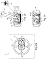
- Fig. 2a shows the fastening device 2 in a plan view. It can be seen here that the fastening element 44 is oriented obliquely to one side. This could occur, for example, if a built-in element that is to be fastened to the surface element 4 cannot be attached via a predefined, fixed point of the surface element 4, but rather the fastening element 44 is inclined from the built-in element to the next, predefined fixed point of the surface element 4 extends.
- Two cutting planes AA and BB are marked, which are in the Figure 2b (Section AA) and Figure 2c (Section BB) are executed. These figures do not fully address each element, which was previously mentioned. Only those in the representation of the Figures 1a and 1b missing elements are examined in more detail here.
- a first guide device 28 with a projection 30 and a groove 32 can be seen.
- a further first guide device 28 can also be seen with a projection 30 and a groove 32.
- the possible pivoting movement of the hollow ball element 22 can be limited exclusively to a first pivot axis 74.
- the flattened shape of the fastening element 44 can also be seen, because only the flanks 56 can be seen in this perspective.
- An intermediate space is created between an inner contour 76 and the flattened flank 56 in the plane of the drawing on the right when the fastening element 44 is in the second rotational position.
- This gap is filled here by a locking pin 78.
- FIG. 2c the section BB is shown, in which the first engagement means 55 in the opening 42 can be seen. Furthermore, two oppositely arranged second guide devices 80 with projections 82 and grooves 84 can be seen. This restricts the pivoting movement of the ball insert 38 to a second pivot axis 86 which is perpendicular to the first pivot axis 74.
- the fastening element 44 when the fastening element 44 is attached, it can move in any direction. However, it is not possible to rotate the hollow ball element 22 or the ball insert 38 about their own axis. This enables the fastening element 44 to be introduced from the outside into the opening 42 of the ball insert 38 in order to subsequently rotate the fastening element without a separate securing of the position of the ball insert 38 or the hollow ball element 22.
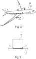
- Fig. 3 shows a very schematic representation of a fastening system 85 with the aid of two fastening devices 2 and a fastening element, by means of which an installation element 92 can be attached to a surface element 4.
- FIG. 8 shows a cabin 88 in an aircraft 90 in which an installation element is arranged which is fastened with at least one fastening device 2 according to the invention.
Landscapes
- Engineering & Computer Science (AREA)
- General Engineering & Computer Science (AREA)
- Mechanical Engineering (AREA)
- Aviation & Aerospace Engineering (AREA)
- Manufacturing & Machinery (AREA)
- Transportation (AREA)
- Pivots And Pivotal Connections (AREA)
Description
- Die Erfindung betrifft ein Befestigungssystem zum Befestigen von Einbauelementen in einer Kabine eines Fahrzeugs. Ferner betrifft die Erfindung eine Kabine für ein Fahrzeug, in der ein Einbauelement mit einem solchen Befestigungssystem befestigt ist. Des Weiteren betrifft die Erfindung ein Fahrzeug, insbesondere ein Flugzeug, welches mit einer solchen Kabine ausgestattet ist.
- Fahrzeuge, die dem Transport von Passagieren dienen, weisen üblicherweise eine Vielzahl von Einbauelementen auf, die unterschiedliche Funktionen bereitstellen. Diese werden je nach Wunsch oder Bedarf in einer Kabine des Fahrzeugs angeordnet und so befestigt, dass während allen denkbaren Bewegungen des Fahrzeugs die masse- und trägheitsbedingten Lasten der Einbauelemente sicher in die Fahrzeugstruktur eingeleitet werden können. Folglich ist eine ausreichend feste und gleichzeitig statisch bestimmte Lagerung für jedes Einbauelement vorzusehen. Je nach Art und Ausführung des Einbauelements kann eine spezifische Lösung für eine Befestigungsvorrichtung eingesetzt werden.
- Um individuelle Ausstattungswünsche unterschiedlicher Betreiber von Fahrzeugen derselben Bauart befriedigen zu können, werden oft modulare Einbauelemente verwendet. Zur Vermeidung einer vollständig variablen Anordnung von Befestigungsvorrichtungen an einer Primärstruktur des betreffenden Fahrzeugs ist die Schaffung kontinuierlicher mechanischer Schnittstellen bekannt, die ohne Beeinflussung der Primärstruktur eine individuelle Anordnung von Befestigungsvorrichtungen erlaubt. Für eine Individualisierung der Anordnung von Einbauelementen ist folglich die Entkopplung von der Primärstruktur des Fahrzeugs ein geeigneter Weg.
- Es sind etwa Befestigungssysteme bekannt, die auf einer Schienenstruktur basieren, welche eine mit einer Fahrzeugstruktur verbundene Schiene aufweist, an der die Einbauelemente über geeignete Beschläge fixierbar sind. Es sind Varianten bekannt, bei denen Fußbodenschienen, welche insbesondere für die Befestigung von Passagiersitzen Verwendung finden, zur Befestigung von Einbauelementen am Boden eingesetzt werden.
-
US 2010/066152 A1 zeigt etwa ein bekanntes Befestigungssystem.EP 3 266 705 Alzeigt etwa ein Tragsystem für eine Kabine eines Fahrzeugs zum Anordnen von Einbauelementen. - Der Erfindung liegt die Aufgabe zugrunde, ein Befestigungssystem vorzuschlagen, welches eine entkoppelte Befestigung eines Einbauelements an einer Primärstruktur erlaubt und flexibel unterschiedliche Relativpositionen zwischen einem Fixierpunkt in der Kabine und dem Einbauelement auch bei toleranzbehafteten Einbaupositionen gewährleisten kann.
- Die Aufgabe wird gelöst durch ein Befestigungssystem zum Befestigen von Einbauelementen in einer Kabine eines Fahrzeugs mit den Merkmalen des unabhängigen Anspruchs 1. Vorteilhafte Ausführungsformen und Weiterbildungen sind den Unteransprüchen und der nachfolgenden Beschreibung zu entnehmen.
- Es wird ein Befestigungssystem zum Befestigen von Einbauelementen in einer Kabine eines Fahrzeugs, mit einem Befestigungselement und mindestens einer Befestigungsvorrichtung vorgeschlagen, die Befestigungsvorrichtung aufweisend ein Flanschgehäuse mit einem darin ausgebildeten Innenraum, ein Verschlusselement, eine in den Innenraum des Flanschgehäuses einsetzbares Hohlkugelelement, einen in das Hohlkugelelement einsetzbaren Kugeleinsatz mit einer erste Eingriffsmittel aufweisenden Öffnung, wobei der Innenraum des Flanschgehäuses eine erste sphärische Lagerfläche aufweist, die zum Verschwenken des Hohlkugelelements mit einer äußeren Oberfläche des Hohlkugelelements korrespondierend ausgebildet ist, wobei eine erste Führungseinrichtung das Verschwenken ausschließlich um eine erste Schwenkachse erlaubt, wobei das Hohlkugelelement innenseitig eine zweite sphärische Lagerfläche aufweist, die zum Verschwenken des Kugeleinsatzes mit einer äußeren Oberfläche des Kugeleinsatzes korrespondierend ausgebildet ist, wobei eine zweite Führungseinrichtung das Verschwenken ausschließlich um eine zweite Schwenkachse erlaubt, wobei das Verschlusselement den Innenraum zumindest abschnittsweise derart verschließt, dass das Hohlkugelelement in dem Innenraum gehalten wird, wobei das Befestigungselement in den Kugeleinsatz einsteckbar ist und zweite Eingriffsmittel aufweist, und wobei die ersten und zweiten Eingriffsmittel derart ausgebildet sind, dass das Befestigungselement in einer ersten Drehposition frei in die Öffnung steckbar ist und in einer zweiten Drehposition die ersten und zweiten Eingriffsmittel ineinander eingreifen.
- Das Flanschgehäuse bildet eine fest einbaubare Basis für die Befestigungsvorrichtung. Das Flanschgehäuse kann an einem Ende einen Flansch aufweisen, welcher sich insbesondere radial über den übrigen Teil des Flanschgehäuses nach außen erstreckt. Der Flansch kann folglich eine Art Anschlag bilden, bis zu dem das Flanschgehäuse in eine Öffnung einer Boden- oder Wandfläche in der Kabine einsteckbar ist. Bevorzugt weist das Flanschgehäuse einen hohlzylindrischen Gehäuseabschnitt auf, der einseitig mit dem Flansch ergänzt ist.
- Das Verschlusselement dient zum Verschließen des Innenraums des Flanschgehäuses, so dass die darin befindlichen, weiter nachfolgend erläuterten Komponenten in dem Innenraum verbleiben. Das Verschlusselement ist bevorzugt, jedoch nicht notwendigerweise, an einem Ende des Flanschgehäuses positionierbar, welches dem Flansch entgegengesetzt ist. In einem besonders einfachen Fall kann das Verschlusselement als ein Ring oder Deckel ausgebildet sein.
- Das in den Innenraum einsetzbare Hohlkugelelement kann als ein ringförmiger Abschnitt einer Kugel ausgeführt sein, wobei die jeweiligen Kappen der Kugel fehlen. Das Hohlkugelelement ist nicht massiv ausgeführt, sondern umschließt ebenfalls einen Hohlraum.
- Der Innenraum des Flanschgehäuses kann das Hohlkugelelement mithilfe der ersten sphärischen Lagerfläche schwenkbar lagern. Das Hohlkugelelement kann einen freien Schwenkwinkel um ihre erste Schwenkachse einnehmen, wobei die Ausrichtung des Schwenkwinkels von der ersten Führungseinrichtung abhängt.
- Gleichermaßen ist der Kugeleinsatz im Innern des Hohlkugelelements schwenkbar gelagert, wobei der freie Schwenkwinkel des Kugeleinsatzes relativ zu dem Hohlkugelelement von der zweiten Führungseinrichtung abhängt. Insgesamt bilden folglich das Flanschgehäuse, das Hohlkugelelement und der Kugeleinsatz eine Art Kardangelenk, da sich, abhängig von der Ausführung der beiden Führungseinrichtungen, der Kugeleinsatz um zwei Achsen innerhalb des Flanschgehäuses verschwenken lässt.
- Durch die Anordnung der Öffnung in dem Kugeleinsatz, in die das Befestigungselement einsteckbar ist, kann die Verschwenkbarkeit des Kugeleinsatzes zum gewünschten Ausrichten des Befestigungselements ausgenutzt werden. Das Befestigungselement ist als ein solches Bauteil zu verstehen, das mit dem zu befestigenden Einbauelement im Eingriff ist und an der Öffnung des Kugeleinsatzes der Befestigungsvorrichtung fixiert wird. Durch die Verschwenkbarkeit des Befestigungselements relativ zu dem Flanschgehäuse einer Befestigungsvorrichtung kann eine gewisse Distanz zwischen einem Befestigungspunkt an dem Einbauelement und der Befestigungsvorrichtung realisiert werden, die strukturfest an dem Fahrzeug positionierbar ist. Dennoch kann jede Kraftrichtung zu einer zuverlässigen, ausreichenden Kraftleitung in die Fahrzeugstruktur genutzt werden.
- Neben der freien Ausrichtbarkeit des Kugeleinsatzes in dem Flanschgehäuse ist ein weiterer Vorteil darin zu sehen, dass das Befestigungselement sehr leicht mit der Öffnung und dem Kugeleinsatz verbindbar ist. Hierzu sind die ersten und zweiten Eingriffsmittel vorgesehen, welche zueinander korrespondierend ausgestaltet sind. Wird das Befestigungselement in der ersten Drehposition in die Öffnung eingesteckt und anschließend in die zweite Drehposition gebracht, wird ein Eingreifen der Eingriffsmittel ineinander hervorgerufen. Dies bedeutet, dass der Abstand zwischen dem Einbauelement und der Befestigungsvorrichtung im gewissen Maße variabel ist. Es ist vorgesehen, dass die Eingriffsmittel unabhängig von der Einstecktiefe miteinander in Eingriff geraten, wenn die zweite Drehposition gewählt wird.
- Insgesamt kann die erfindungsgemäße Befestigungsvorrichtung daher eine Krafteinleitung aus einer weitgehend beliebigen Position in eine strukturfest angebrachte Befestigungsvorrichtung durchführen und gleichzeitig Mittel zum Ausgleichen von montagebedingten Toleranzen durchführen.
- An dieser Stelle sei darauf hingewiesen, dass zum Anbinden des Befestigungselements an dem Einbauelement eine einfache Kugelbuchse ausreichen könnte, die wie ein Hohlkugelelement ausgestaltet ist und schwenkbar gelagert ist. Allerdings ist es insbesondere denkbar und bevorzugt, eine zweite Befestigungsvorrichtung vorzusehen, durch die sich ein gemeinsames Befestigungselement erstreckt. Das Befestigungssystem kann folglich zwei Befestigungsvorrichtungen umfassen, wobei eine an dem Einbauelement angeordnet ist, die andere strukturfest an dem entsprechenden Flächenelement. Durch Ausnutzen der ersten und zweiten Eingriffsmittel in beiden Kugeleinsätzen und dem Befestigungselement kann das Befestigungselement derart mit beiden Kugeleinsätzen verbunden werden, dass sämtliche montagebedingten Toleranzen ausgeglichen werden und die bei der Montage eingenommene Relativposition zwischen dem Einbauelement und einem strukturfesten Punkt starr beibehalten werden.
- Weiterhin sei darauf hingewiesen, dass zur festen Verbindung eines Einbauelements mit einem Flächenelement mehrere strukturfeste Punkte und mehrere Anbindungspunkte des Einbauelements einbezogen werden.
- In einer vorteilhaften Ausführungsform stehen die erste Schwenkachse und die zweite Schwenkachse senkrecht zueinander. Dadurch wird praktisch ein vollkardanisches Gelenk bereitgestellt, das eine völlig beliebige Stellung des Kugeleinsatzes relativ zu dem Flanschgehäuse ermöglicht. Hierbei ist allerdings anzumerken, dass bevorzugt keine der beiden Schwenkachsen so vorzusehen ist, dass sich die Hohlkugel und/oder der Kugeleinsatz nur um ihre eigene Achse drehen können.
- In einer vorteilhaften Ausführungsform stehen die erste Schwenkachse und die zweite Schwenkachse senkrecht zu einer Haupterstreckungsrichtung der Öffnung des Kugeleinsatzes. Damit kann ausgeschlossen werden, dass sich eines dieser Elemente um eine Achse parallel zu dem Befestigungselement drehen lässt. Die Befestigungsvorrichtung erlaubt daher das Einsetzen des Befestigungselements und dessen Fixierung vollkommen ohne die Notwendigkeit, ein Werkzeug zum Halten des Kugeleinsatzes einzusetzen. Insbesondere bei zueinander senkrecht stehenden Schwenkachsen bleibt jedoch vollständig eine völlig beliebige Ausrichtung des Kugeleinsatzes gewährleistet.
- Die Befestigungsvorrichtung kann ferner eine Flanschmutter mit einem ersten Außengewinde aufweisen, die in ein erstes Innengewinde des Flanschgehäuses einschraubbar ist, so dass das Flanschgehäuse und die Flanschmutter in einem Ausschnitt eines Flächenbauteils befestigbar sind. Das Anordnen der Befestigungsvorrichtung in einem Flächenbauteil, das heißt einer Wand- oder Bodenfläche, kann daher durch Bereitstellen eines Ausschnitts, das Einsetzen des Flanschgehäuses in den Ausschnitt und das Verspannen des Flanschgehäuses mit der Flanschmutter realisiert werden. Bevorzugt weist die Flanschmutter ebenso einen Flansch auf, der als Absatz oder Anschlag fungiert. Durch Einschrauben der Flanschmutter in das Flanschgehäuse wird folglich ein Randbereich um den Ausschnitt herum zangenartig umgriffen. Das Flanschgehäuse ist dann fest an dem Flächenelement angeordnet und erlaubt eine wirksame Krafteinleitung. Besonders bevorzugt ist die Flanschmutter ebenfalls als ein hohlzylindrisches Bauteil ausgeführt, wobei ein hohlzylindrischer Abschnitt auf einer Seite den Flansch aufweist.
- Bevorzugt weist das Verschlusselement an einer in den Innenraum gewandten Seite eine dritte sphärische Lagerfläche auf, die auf einem Krümmungsradius basiert, der einem Krümmungsradius der zweiten sphärischen Lagerfläche entspricht, so dass sich die zweite sphärische Lagerfläche und die dritte sphärische Lagerfläche zumindest bereichsweise ergänzen. Folglich bilden das Hohlkugelelement und das Verschlusselement zusammen eine vergrößerte sphärische Lagerfläche. Hierdurch kann die Lagerung des Kugeleinsatzes dahingehend verbessert werden, dass die Schwenkbarkeit vergrößert wird, ohne dass zwangsläufig das Hohlkugelelement vergrößert werden muss.
- Das Befestigungselement ist bevorzugt länglich und die zweiten Eingriffsmittel sind ausschließlich auf zwei einander gegenüberliegenden Längsseiten angeordnet, wobei die ersten Eingriffsmittel in der Öffnung komplementär dazu angeordnet sind, so dass durch Verdrehen des Befestigungselements um eine Längsachse ein Eingriff herstellbar oder lösbar ist. Die ersten und zweiten Eingriffsmittel können beispielsweise in Form einer Verzahnung ausgeführt sein. Die Verzahnung kann eine rillenförmige Struktur darstellen. Eine Art Gewindesteigung ist möglich, jedoch nicht erforderlich. Durch diese Anordnung ergeben sich in den Profilquerschnitten des Befestigungselements sowie der Öffnung zwei einander gegenüberliegende, diskrete, verzahnte Abschnitte. Die Öffnung in dem Kugeleinsatz ist dabei so bemessen, dass sich das Befestigungselement um seine Längsachse in der Öffnung drehen lässt und nur in der zweiten Drehposition ein Eingriff mit den ersten Eingriffsmitteln erfolgt. In der ersten Drehposition liegen die zweiten Eingriffsmittel des Befestigungselements in den Zwischenräumen der Öffnung zwischen den ersten Eingriffsmitteln. Dadurch ist ein freies, ungehindertes Einstecken entlang der Längsachse des Befestigungselements und der Öffnung denkbar.
- Beim Einnehmen der zweiten Drehposition sind diese Zwischenräume frei. Bevorzugt weist die Befestigungsvorrichtung mindestens einen Sicherungsstift auf, der in der zweiten Drehposition des Befestigungselements zwischen einer Innenkontur der Öffnung des Kugeleinsatzes und dem Befestigungselement einsteckbar ist. Dadurch wird dieser Zwischenraum weitgehend ausgefüllt und das Rückdrehen des Befestigungselements in die erste Drehposition wird dadurch verhindert. Der Sicherungsstift stellt folglich eine Sicherung zum Verhindern des Lösens des Befestigungselements dar, die mechanisch besonders einfach aufgebaut ist.
- Der Sicherungsstift ist in einer vorteilhaften Ausführungsform dazu ausgebildet, beim Einstecken in die Öffnung elastisch verformt zu werden und eine kraftschlüssige und/oder formschlüssige Verbindung mit der Öffnung und/oder dem Befestigungselement einzugehen. Durch diese elastische Verformbarkeit wird gleichzeitig ein versehentliches Lösen des Sicherungsstiftes selbst verhindert. Der Sicherungsstift kann sich hierbei etwa in der Öffnung verkeilen.
- Bevorzugt weist das Befestigungssystem zwei Befestigungsvorrichtungen auf, wobei das Befestigungselement sich durch die Öffnungen der Kugeleinsätze beider Befestigungsvorrichtungen erstreckt. Damit können die Vorteile der Befestigungsvorrichtungen sowohl an dem strukturfesten Flächenelement als auch an dem Einbauelement genutzt werden und weiterhin kann ein Toleranzausgleich durch entsprechendes Eingreifen der ersten Eingriffsmittel und der zweiten Eingriffsmittel an zwei Bereichen des Befestigungselements erfolgen.
- Die Aufgabe wird ferner gelöst durch eine Kabine für ein Fahrzeug, aufweisend mindestens ein Flächenelement und mindestens ein Einbauelement, das über das vorangehend genannte Befestigungssystem mit dem mindestens einen Flächenelement verbunden ist, wobei das Flächenelement hierzu einen Ausschnitt zur Aufnahme der mindestens einen Befestigungsvorrichtung aufweist.
- Die Erfindung betrifft ferner ein Fahrzeug mit einer solchen Kabine. In einer vorteilhaften Ausführungsform ist das Fahrzeug ein Flugzeug.
- Weitere Merkmale, Vorteile und Anwendungsmöglichkeiten der vorliegenden Erfindung ergeben sich aus der nachfolgenden Beschreibung der Ausführungsbeispiele und den Figuren. In den Figuren stehen weiterhin gleiche Bezugszeichen für gleiche oder ähnliche Objekte.
-
Fig. 1a und 1b zeigen eine Befestigungsvorrichtung an einem Flächenelement mit einem Befestigungselement. -
Fig. 2a, 2b und 2c zeigen eine Draufsicht (Fig. 2a ), und zwei unterschiedliche vertikale Schnittdarstellungen (Fig. 2b und 2c ). -
Fig. 3 zeigt ein Befestigungssystem mit zwei Befestigungsvorrichtungen in einer sehr schematischen Darstellung. -
Fig. 4 zeigt ein Flugzeug mit einer Kabine sowie einem darin angeordneten Einbauelement, welches über ein erfindungsgemäßes Befestigungssystem in der Kabine befestigt ist. -
Fig. 1a und 1b zeigen eine erfindungsgemäße Befestigungsvorrichtung 2 in einer dreidimensionalen Schnittdarstellung. InFig. 1b wird ein Teil der Befestigungsvorrichtung 2 von unten gezeigt. Zur Illustration ist die Befestigungsvorrichtung 2 in ein Flächenelement 4 integriert, das beispielsweise ein Boden- oder Wandelement in einer Kabine eines Fahrzeugs sein kann. Hierzu weist das Flächenelement 4 einen Ausschnitt 6 auf, in dem ein Flanschgehäuse 8 angeordnet ist. Das Flanschgehäuse 8 weist einen hohlzylindrischen Abschnitt 10 auf, an den sich ein ringförmiger Flansch 12 anschließt. Der hohlzylindrische Abschnitt 10 ist vollständig in die Ausnehmung 6 eingeschoben, so dass der Flansch 12 auf dem Flächenelement 4 aufliegt. Exemplarisch weist der Flansch 12 auf einer von dem Flächenelement 4 abgewandten Seite Betätigungsmittel 14 auf, in die ein Werkzeug einsteckbar ist, um das Flanschgehäuse 8 drehen bzw. in einer festen Drehposition halten zu können. - In dem Flanschgehäuse 8 ist ein Innenraum 16 gebildet, der in einer Durchführöffnung 18 in dem Flansch 12 und einer davon entgegengesetzt angeordneten Aufbauöffnung 20 mündet.
- In dem Innenraum 16 ist ein Hohlkugelelement 22 angeordnet, das eine äußere Oberfläche 24 aufweist, die kugelförmig gekrümmt ist. Hiermit korrespondiert eine erste sphärische Lagerfläche 26, an der die äußere Oberfläche 24 des Hohlkugelelements 22 im Flächenkontakt gehalten wird. Das Hohlkugelelement 22 kann durch die korrespondierende Formgebung an der ersten sphärischen Lagerfläche 26 bewegt werden.
- Eine erste Führungseinrichtung 28 in Form eines Vorsprungs 30 und einer damit korrespondierenden Vertiefung 32 in dem Flanschgehäuse 8 kann jedoch die Beweglichkeit der Hohlkugel 22 in dem Innenraum 16 eingeschränkt werden. Die erste Führungseinrichtung 28 ist an zwei einander gegenüberliegenden Seiten der Hohlkugel 22 angeordnet, so dass hierdurch eine Schwenkebene definiert ist. In dieser Darstellung ist lediglich eine erste Führungseinrichtung 28 sichtbar, diese wird jedoch auf den nachfolgenden Zeichnungen gezeigt.
- Das Hohlkugelelement 22 weist innenseitig eine zweite sphärische Lagerfläche 34 auf, die mit einer äußeren Oberfläche 36 eines Kugeleinsatzes 38 korrespondiert. Der Kugeleinsatz 38 ist folglich in dem Hohlkugelelement 22 schwenkbar gelagert und weist hierzu eine äußere Oberfläche 40 auf, die ebenfalls kugelförmig gekrümmt ist. Ferner ist dort eine Öffnung 42 vorhanden, in die ein Befestigungselement 44 einsteckbar ist. Der Kugeleinsatz 38 besitzt eine hier nicht sichtbare zweite Führungseinrichtung, welche die Schwenkbewegung des Kugeleinsatzes 38 analog zu der ersten Führungseinrichtung 28 beschränkt. Die Schwenkachsen des Hohlkugelelements 22 und des Kugeleinsatzes 38 sind senkrecht zueinander angeordnet.
- Das Befestigungselement 44 ist wie ein Schraubbolzen gestaltet und weist folglich einen Schaft 46 auf, der sich durch die Öffnung 42 erstreckt. Ein Befestigungsende 48 des Befestigungselements 44 weist einen Kopf 50 auf, der mit einer profilierten Vertiefung 52 zum Verbinden mit einem Werkzeug ausgestattet ist. An einem dem Kopf 50 entgegengesetzten Ende sind zweite Eingriffsmittel 54 an zwei einander gegenüberliegenden Längsseiten angeordnet, wobei die zwischen den zweiten Eingriffsmitteln 54 liegenden Bereiche des Befestigungselements 44 in Form abgeflachter Flanken 56 realisiert sind. In dieser Darstellung sind erste Eingriffsmittel in dem Kugeleinsatz 38 nicht sichtbar, werden jedoch ebenfalls in den nachfolgenden Zeichnungen dargestellt.
- Das Flanschgehäuse 8 ist über eine Flanschmutter 58 an dem Flächenelement angeordnet. Hierzu weist das Flanschgehäuse 8 ein erstes Innengewinde 60 auf, das mit einem ersten Außengewinde 62 der Flanschmutter 58 korrespondiert. Durch Anordnen eines Flansches 64 an einem ansonsten hohlzylindrischen Abschnitt 66 kann die Flanschmutter 58 in das Flanschgehäuse 8 eingeschraubt werden, bis der Flansch 64 an dem Flächenelement 4 aufliegt. Hierdurch wird die Befestigungsvorrichtung 2 an dem Flächenelement 4 vollständig form- und kraftschlüssig integriert. Das Flächenelement 4 wird von den beiden Flanschen 12 und 64 zangenartig auf einem ringförmigen Rand zangenartig umgriffen.
- Zum Befestigen bzw. Halten der in dem Innenraum 16 angeordneten Komponenten ist ein Verschlusselement 66 vorgesehen, das ringförmig gestaltet in die Verschlussmutter 58 geschraubt werden kann. Hierzu weist das Verschlusselement 66 ein zweites Außengewinde 68 auf, das mit einem zweiten Innengewinde 70 korrespondiert. Zusätzlich weist das Verschlusselement 66 eine ringförmig ausgebildete, dritte sphärische Lagerfläche 72 auf, die auf einem Krümmungsradius basiert, der einem Krümmungsradius der zweiten sphärischen Lagerfläche 40 der Hohlkugel 22 entspricht. Das Hohlkugelelement 22 wird folglich an einer Unterseite, das heißt von dem Flansch 12 abgewandt, der Befestigungsvorrichtung 2 ergänzt. Wie in
Fig. 1a und 1b ersichtlich ist, kann auch die Schwenkbewegung des Hohlkugelelements 22 durch einen erzwungenen Flächenkontakt mit dem Verschlusselement 66 begrenzt werden. - Die weiteren Zusammenhänge sind den nachfolgenden Figuren zu entnehmen.
Fig. 2a zeigt die Befestigungsvorrichtung 2 in einer Draufsicht. Hier ist ersichtlich, dass das Befestigungselement 44 zu einer Seite schräg ausgerichtet ist. Dies könnte beispielsweise dann auftreten, wenn ein Einbauelement, das an dem Flächenelement 4 zu befestigen ist, nicht über einen vordefinierten, festen Punkt des Flächenelements 4 anbringbar ist, sondern sich das Befestigungselement 44 von dem Einbauelement schräg zu dem nächsten, vordefinierten festen Punkt des Flächenelements 4 erstreckt. Es sind zwei Schnittebenen A-A und B-B markiert, welche in denFig. 2b (Schnitt A-A) undFig. 2c (Schnitt B-B) ausgeführt sind. In diesen Figuren wird nicht vollständig auf jedes Element eingegangen, was zuvor bereits erwähnt wurde. Lediglich die in der Darstellung derFig. 1a und 1b fehlenden Elemente werden hier etwas eingehender beleuchtet. - In
Fig. 2b ist eine erste Führungseinrichtung 28 mit einem Vorsprung 30 und einer Nut 32 zu sehen. Auf der gegenüberliegenden Seite des Hohlkugelelements 22 ist eine weitere erste Führungseinrichtung 28 ebenso mit einem Vorsprung 30 und einer Nut 32 ersichtlich. Hierdurch kann die mögliche Schwenkbewegung des Hohlkugelelements 22 ausschließlich auf eine erste Schwenkachse 74 beschränkt werden. - In dieser Darstellung ist ferner die abgeflachte Form des Befestigungselements 44 ersichtlich, denn in dieser Perspektive sind nur die Flanken 56 erkennbar. Zwischen einer Innenkontur 76 und der abgeflachten Flanke 56 in der Zeichnungsebene rechts entsteht ein Zwischenraum, wenn das Befestigungselement 44 in der zweiten Drehposition liegt. Dieser Zwischenraum ist hier durch einen Sicherungsstift 78 ausgefüllt. Dieser könnte elastisch verformbar sein und eine gewisse Vorspannung besitzen. Durch das Eindrücken des Sicherungsstifts 78 zwischen die Flanke 56 und die Innenkontur 76 des Kugeleinsatzes wird der Sicherungsstift 78 zumindest stellenweise stark gestaucht, so dass seine Position gesichert wird.
- In
Fig. 2c ist der Schnitt B-B gezeigt, in dem erste Eingriffsmittel 55 in der Öffnung 42 ersichtlich sind. Weiterhin sind zwei einander gegenüberliegend angeordnete zweite Führungseinrichtungen 80 mit Vorsprüngen 82 und Nuten 84 zu sehen. Durch diese wird die Schwenkbewegung des Kugeleinsatzes 38 auf eine zweite Schwenkachse 86 beschränkt, welche senkrecht zu der ersten Schwenkachse 74 liegt. Insgesamt kann bei befestigtem Befestigungselement 44 dieses eine Bewegung in beliebige Richtungen durchführen. Allerdings ist es nicht möglich, das Hohlkugelelement 22 oder den Kugeleinsatz 38 um ihre eigene Achse zu drehen. Dadurch wird dem Befestigungselement 44 ermöglicht, von außen in die Öffnung 42 des Kugeleinsatzes 38 eingeführt zu werden, um anschließend ohne eine separate Sicherung der Position des Kugeleinsatzes 38 oder des Hohlkugelelements 22 eine Rotation des Befestigungselements durchzuführen. -
Fig. 3 zeigt eine sehr schematische Darstellung eines Befestigungssystems 85 mit Hilfe zweier Befestigungsvorrichtungen 2 und einem Befestigungselement, durch das ein Einbauelement 92 an einem Flächenelement 4 anbringbar ist. -
Fig. 4 zeigt schließlich eine Kabine 88 in einem Flugzeug 90, in der ein Einbauelement angeordnet ist, das mit mindestens einer erfindungsgemäßen Befestigungsvorrichtung 2 befestigt ist. - Ergänzend sei darauf hingewiesen, dass "aufweisend" keine anderen Elemente oder Schritte ausschließt, und "ein" oder "eine" keine Vielzahl ausschließt. Ferner sei darauf hingewiesen, dass Merkmale, die mit Verweis auf eines der obigen Ausführungsbeispiele beschrieben worden sind, auch in Kombination mit anderen Merkmalen anderer oben beschriebener Ausführungsbeispiele verwendet werden können. Bezugszeichen in den Ansprüchen sind nicht als Einschränkung anzusehen.
Claims (13)
- Befestigungssystem (85) zum Befestigen von Einbauelementen (92) in einer Kabine (90) eines Fahrzeugs (88), mit einem Befestigungselement (44) und mindestens einer Befestigungsvorrichtung (2), die Befestigungsvorrichtung (2) aufweisend:- ein Flanschgehäuse (8) mit einem darin ausgebildeten Innenraum (16),- ein Verschlusselement (58),- ein in den Innenraum (16) des Flanschgehäuses (8) einsetzbares Hohlkugelelement (22), und- einen in das Hohlkugelelement (22) einsetzbaren Kugeleinsatz (38) mit einer erste Eingriffsmittel (55) aufweisenden Öffnung (42),wobei der Innenraum (16) des Flanschgehäuses (8) eine erste sphärische Lagerfläche (26) aufweist, die zum Verschwenken des Hohlkugelelements (22) mit einer äußeren Oberfläche (24) des Hohlkugelelements (22) korrespondierend ausgebildet ist, wobei eine erste Führungseinrichtung (28) das Verschwenken ausschließlich um eine erste Schwenkachse (74) erlaubt,
wobei das Hohlkugelelement (22) innenseitig eine zweite sphärische Lagerfläche (34) aufweist, die zum Verschwenken des Kugeleinsatzes (38) mit einer äußeren Oberfläche (36) des Kugeleinsatzes (38) korrespondierend ausgebildet ist, wobei eine zweite Führungseinrichtung (80) das Verschwenken ausschließlich um eine zweite Schwenkachse (86) erlaubt,
wobei das Verschlusselement (58) den Innenraum (16) zumindest abschnittsweise derart verschließt, dass das Hohlkugelelement (22) in dem Innenraum (16) gehalten wird,
wobei das Befestigungselement (44) in den Kugeleinsatz (38) einsteckbar ist und zweite Eingriffsmittel (54) aufweist, und
wobei die ersten und zweiten Eingriffsmittel (55, 54) derart ausgebildet sind, dass das Befestigungselement in einer ersten Drehposition frei in die Öffnung (42) steckbar ist und in einer zweiten Drehposition die ersten und zweiten Eingriffsmittel (55, 54) ineinander eingreifen. - Befestigungssystem (85) nach Anspruch 1, wobei die erste Schwenkachse (74) und die zweite Schwenkachse (86) senkrecht zueinander stehen.
- Befestigungssystem (85) nach Anspruch 1 oder 2, wobei die erste Schwenkachse (74) und die zweite Schwenkachse (86) senkrecht zu einer Haupterstreckungsrichtung der Öffnung (42) des Kugeleinsatzes (38) stehen.
- Befestigungssystem (85) nach einem der vorhergehenden Ansprüche, ferner aufweisend eine Flanschmutter (58) mit einem ersten Außengewinde (62), die in ein erstes Innengewinde (60) des Flanschgehäuses (8) einschraubbar ist, so dass das Flanschgehäuse (8) und die Flanschmutter (58) in einem Ausschnitt eines Flächenbauteils (4) befestigbar sind.
- Befestigungssystem (85) nach einem der vorhergehenden Ansprüche, wobei das Verschlusselement (66) an einer in den Innenraum (16) gewandten Seite eine dritte sphärische Lagerfläche (72) aufweist, die auf einem Krümmungsradius basiert, der einem Krümmungsradius der zweiten sphärischen Lagerfläche (40) entspricht, so dass sich die zweite sphärische Lagerfläche (40) und die dritte sphärische Lagerfläche (72) zumindest bereichsweise ergänzen.
- Befestigungssystem (85) nach einem der vorhergehenden Ansprüche, wobei das Verschlusselement (66) im Wesentlichen ringförmig ausgestaltet ist und ein zweites Außengewinde (68) aufweist, das mit einem zweiten Innengewinde (70) korrespondiert, welches symmetrisch zu dem Innenraum (16) angeordnet ist.
- Befestigungssystem (85) nach einem der vorhergehenden Ansprüche, wobei das Befestigungselement (44) länglich ist und die zweiten Eingriffsmittel (54) ausschließlich auf zwei einander gegenüberliegende Längsseiten angeordnet sind, wobei die ersten Eingriffsmittel (55) in der Öffnung (42) komplementär dazu angeordnet sind, so dass durch Verdrehen des Befestigungselements (44) um eine Längsachse ein Eingriff herstellbar oder lösbar ist.
- Befestigungssystem (85) nach Anspruch 7, ferner aufweisend mindestens einen Sicherungsstift (78), der in der zweiten Drehposition des Befestigungselements (44) zwischen eine Innenkontur (76) der Öffnung (42) des Kugeleinsatzes (38) und dem Befestigungselement (44) einsteckbar ist.
- Befestigungssystem (85) nach Anspruch 8, wobei der Sicherungsstift (78) dazu ausgebildet ist, beim Einstecken in die Öffnung (42) elastisch verformt zu werden und eine kraftschlüssige und/oder formschlüssige Verbindung mit der Öffnung (42) und/oder dem Befestigungselement (44) einzugehen.
- Befestigungssystem (85) nach einem der vorhergehenden Ansprüche, das zwei Befestigungsvorrichtungen (2) aufweist, wobei das Befestigungselement (44) sich durch die Öffnungen (42) der Kugeleinsätze (38) beider Befestigungsvorrichtungen (2) erstreckt.
- Kabine (90) für ein Fahrzeug (88), aufweisend mindestens ein Flächenelement (4) und mindestens ein Einbauelement (92), das über das Befestigungssystem (85) nach einem der Ansprüche 1 bis 10 mit dem mindestens einen Flächenelement (4) verbunden ist.
- Fahrzeug (88) mit einer Kabine (90) nach Anspruch 11.
- Fahrzeug (88) nach Anspruch 12, wobei das Fahrzeug (88) ein Flugzeug (88) ist.
Applications Claiming Priority (1)
| Application Number | Priority Date | Filing Date | Title |
|---|---|---|---|
| DE102018109995.9A DE102018109995A1 (de) | 2018-04-25 | 2018-04-25 | Befestigungssystem zum Befestigen von Einbauelementen in einer Kabine eines Fahrzeugs |
Publications (2)
| Publication Number | Publication Date |
|---|---|
| EP3561322A1 EP3561322A1 (de) | 2019-10-30 |
| EP3561322B1 true EP3561322B1 (de) | 2021-03-17 |
Family
ID=66175157
Family Applications (1)
| Application Number | Title | Priority Date | Filing Date |
|---|---|---|---|
| EP19168296.2A Active EP3561322B1 (de) | 2018-04-25 | 2019-04-10 | Befestigungssystem zum befestigen von einbauelementen in einer kabine eines fahrzeugs |
Country Status (4)
| Country | Link |
|---|---|
| US (1) | US11072438B2 (de) |
| EP (1) | EP3561322B1 (de) |
| CN (1) | CN110395405A (de) |
| DE (1) | DE102018109995A1 (de) |
Cited By (1)
| Publication number | Priority date | Publication date | Assignee | Title |
|---|---|---|---|---|
| EP4187112A1 (de) | 2021-11-30 | 2023-05-31 | Airbus Operations GmbH | Verbindungsvorrichtung für eine positionsverstellbare querverbindung zweier bauteile |
Families Citing this family (12)
| Publication number | Priority date | Publication date | Assignee | Title |
|---|---|---|---|---|
| US10822091B2 (en) * | 2018-03-06 | 2020-11-03 | Bombardier Inc. | Passenger seat for aircraft |
| US20200386260A1 (en) * | 2019-06-06 | 2020-12-10 | The Boeing Company | Swivel Foot Screw Assembly |
| DE102020101238A1 (de) * | 2020-01-20 | 2021-07-22 | Oase Gmbh | Wasserspiel zur Erzeugung eines beleuchteten Wasserbildes |
| DE102020103626B4 (de) | 2020-02-12 | 2023-02-09 | Airbus Operations Gmbh | Gelenkverbindung und Verfahren zum Befestigen einer Fahrzeugeinrichtung an einer Primärstruktur eines Fahrzeugs, Fachwerkstruktur mit einer Gelenkverbindung sowie Luftfahrzeug mit einer Gelenkverbindung |
| CN112032156B (zh) * | 2020-07-21 | 2021-06-15 | 中国科学院长春光学精密机械与物理研究所 | 一种高精度复位机构及方法 |
| KR20230043394A (ko) * | 2021-09-24 | 2023-03-31 | 현대자동차주식회사 | 자동차용 리클라이닝 시트 조립 장치 |
| US12523244B2 (en) * | 2021-10-28 | 2026-01-13 | Honeywell International Inc. | Locking positioning systems |
| ES3029238T3 (en) | 2022-01-26 | 2025-06-23 | Airbus Operations Gmbh | Coupling device for a connecting rod |
| US12504035B2 (en) * | 2023-02-07 | 2025-12-23 | B/E Aerospace, Inc. | Adjustable height fastener |
| EP4470908A1 (de) * | 2023-05-31 | 2024-12-04 | Airbus Operations GmbH | Montageschiene |
| EP4484275A1 (de) * | 2023-06-28 | 2025-01-01 | Airbus Operations GmbH | Montageschnittstelle für fachwerke |
| DE102024126376B3 (de) * | 2024-09-12 | 2026-01-29 | Airbus Defence and Space GmbH | Verriegelungsvorrichtung für einen Service-Zugang an einer Außenstruktur eines Luftfahrzeugs, Service-Zugang, Luftfahrzeug sowie Verfahren zur Herstellung einer Verriegelungsvorrichtung für einen Service-Zugang an einer Außenstruktur eines Luftfahrzeugs |
Family Cites Families (22)
| Publication number | Priority date | Publication date | Assignee | Title |
|---|---|---|---|---|
| US2853112A (en) | 1954-04-27 | 1958-09-23 | Illinois Tool Works | Locked bolt and shear resisting grommet means |
| DE1826871U (de) | 1960-12-12 | 1961-02-16 | Ehrenreich & Cie A | Kugelgelenk mit einstellbarer gaengigkeit, vorzugsweise fuer vorderachsteile von kraftfahrzeugen. |
| GB1060031A (en) * | 1965-01-06 | 1967-02-22 | British Aircraft Corp Ltd | Improvements in mountings for aircraft windscreens |
| US5795122A (en) | 1994-09-21 | 1998-08-18 | Bowers; Ned C. | Adjustable quick connect fastener for accommodating panels of various thicknesses |
| SE518384C2 (sv) | 2001-05-03 | 2002-10-01 | Johansson Ab C E | Styrning för kulled |
| DE102007018326B4 (de) * | 2007-04-18 | 2010-05-06 | Airbus Deutschland Gmbh | Lagerung zur Befestigung von Treppen in einem Flugzeug |
| US7770981B2 (en) | 2008-09-17 | 2010-08-10 | Honda Motor Company, Ltd. | Dump bed connection apparatus and vehicles including same |
| DE102011011976B4 (de) * | 2011-02-22 | 2013-11-14 | Airbus Operations Gmbh | Dekompressionsanordnung für ein Luftfahrzeug |
| GB201110436D0 (en) | 2011-06-21 | 2011-08-03 | Rolls Royce Plc | Joint assembly |
| WO2014088600A1 (en) * | 2012-12-08 | 2014-06-12 | Goldbaum Harold J | Rapid-engaging and positive-locking threaded configuration |
| DE102012223609A1 (de) * | 2012-12-18 | 2014-06-18 | Zf Friedrichshafen Ag | Gelenkeinrichtung für ein Kraftfahrzeug |
| TWI518255B (zh) * | 2014-06-18 | 2016-01-21 | Kabo Tool Co | To prevent loosening of the screw assembly |
| DE202014105325U1 (de) * | 2014-11-05 | 2015-01-21 | Schwinn Beschläge GmbH | Befestigungsvorrichtung zur Festlegung eines Möbelelements an einer Oberfläche |
| US20160356309A1 (en) * | 2015-06-05 | 2016-12-08 | Coxon Precise Industrial Co., Ltd. | Adjustable ball-type universal joint |
| EP3322905B1 (de) * | 2015-07-14 | 2025-11-26 | Milwaukee Electric Tool Corporation | Schnellverbindungsmechanismus für eine zugbolzenanordnung |
| US9957989B2 (en) * | 2016-05-31 | 2018-05-01 | The Boeing Company | Swivel nut assembly |
| EP3266706B1 (de) * | 2016-07-05 | 2019-03-20 | Airbus Operations GmbH | Flugzeuginstallationseinrichtung und installationssystem zur montage einer überkopfgepäckablage |
| EP3266705B1 (de) * | 2016-07-05 | 2019-06-26 | Airbus Operations GmbH | Innenraumkomponententrägersystem und verfahren zur montage eines flugzeuginnenraumkomponententrägersystems |
| EP3254951B1 (de) * | 2016-06-06 | 2021-11-03 | Airbus Operations GmbH | Befestigungsanordnung zur befestigung eines ersten objekts an einem zweiten objekt mit variablem abstand |
| JP6335986B2 (ja) * | 2016-08-25 | 2018-05-30 | 日本発條株式会社 | スタビリンク |
| US10480567B2 (en) * | 2017-10-18 | 2019-11-19 | Advanced Machine & Engineering Co. | Ball element with retracting stud |
| DE102017131130B4 (de) * | 2017-12-22 | 2023-05-04 | Airbus Operations Gmbh | Befestigungssystem zum Befestigen einer Komponente an einer Rumpfstruktur |
-
2018
- 2018-04-25 DE DE102018109995.9A patent/DE102018109995A1/de not_active Withdrawn
-
2019
- 2019-04-05 US US16/376,753 patent/US11072438B2/en active Active
- 2019-04-10 EP EP19168296.2A patent/EP3561322B1/de active Active
- 2019-04-25 CN CN201910338526.3A patent/CN110395405A/zh active Pending
Non-Patent Citations (1)
| Title |
|---|
| None * |
Cited By (1)
| Publication number | Priority date | Publication date | Assignee | Title |
|---|---|---|---|---|
| EP4187112A1 (de) | 2021-11-30 | 2023-05-31 | Airbus Operations GmbH | Verbindungsvorrichtung für eine positionsverstellbare querverbindung zweier bauteile |
Also Published As
| Publication number | Publication date |
|---|---|
| US11072438B2 (en) | 2021-07-27 |
| DE102018109995A1 (de) | 2019-10-31 |
| EP3561322A1 (de) | 2019-10-30 |
| US20190329907A1 (en) | 2019-10-31 |
| CN110395405A (zh) | 2019-11-01 |
Similar Documents
| Publication | Publication Date | Title |
|---|---|---|
| EP3561322B1 (de) | Befestigungssystem zum befestigen von einbauelementen in einer kabine eines fahrzeugs | |
| EP1805427B1 (de) | Zug-druck-stange | |
| EP0643232B1 (de) | Mutter mit Druckring | |
| EP2215370B1 (de) | Haltenocken für einen drehverschluss | |
| DE102006004678A1 (de) | Montageeinheit für die Befestigungsöse eines Gurtschlosses | |
| DE4445724A1 (de) | Befestigungsanordnung von Platten | |
| CH711751B1 (de) | Befestigungseinrichtung für ein in Schienen einer Bodenstruktur eines Flugzeuginnenraumes zu befestigendes Bauteil. | |
| DE102011085450A1 (de) | Anbindungsanordnung, Verbindungseinrichtung sowie Verfahren | |
| EP3581811B1 (de) | System zur befestigung einer ersten komponente an einer zweiten komponente | |
| DE69117867T2 (de) | Endauschlussstück | |
| DE102018103514A1 (de) | Befestigungssystem zum Befestigen von Einbauten an einer Schiene in einem Fahrzeug | |
| EP4086173B1 (de) | Befestigungsvorrichtung zur lösbaren verbindung mit einer lochschiene eines flugzeugs und montageverfahren | |
| DE19719915C2 (de) | Gabelglied für einen Leitwerkanschluß | |
| EP1424498A1 (de) | Schwingungsdämpfende lösbare Rast-/Schraub-Verbindungsanordnung | |
| EP4219304B1 (de) | Kopplungsvorrichtung für eine verbindungsstange | |
| EP2907696A1 (de) | Sperrbalken für ein Ladungssicherungssystem | |
| DE102019114519B4 (de) | Montagesystem mit Justiermöglichkeit, Gepäckfach sowie Fahrzeug mit Montagesystem und Verfahren zur Installation und Justierung eines Bauteils | |
| EP4286275A1 (de) | Befestigungssystem mit toleranzkompensation für einen innenraum eines luftfahrzeugs | |
| DE102021102576A1 (de) | Gelenkverbinder zum Verbinden mehrerer Bauteile | |
| DE102018207973A1 (de) | Befestigungssystem, Verfahren zur Befestigung, Verfahren zur Montage und Kraftfahrzeug | |
| DE102018101836B4 (de) | Befestigungssystem zum Befestigen von Einbauten in einem Fahrzeug | |
| DE102016211673A1 (de) | Verfahren zur Herstellung einer Schalteinheit | |
| DE102024126376B3 (de) | Verriegelungsvorrichtung für einen Service-Zugang an einer Außenstruktur eines Luftfahrzeugs, Service-Zugang, Luftfahrzeug sowie Verfahren zur Herstellung einer Verriegelungsvorrichtung für einen Service-Zugang an einer Außenstruktur eines Luftfahrzeugs | |
| DE102020123291A1 (de) | Befestigungselement zum Befestigen eines Anbauteils im Innenraum eines Kraftfahrzeuges | |
| DE102019008731A1 (de) | Schraubanordnung |
Legal Events
| Date | Code | Title | Description |
|---|---|---|---|
| PUAI | Public reference made under article 153(3) epc to a published international application that has entered the european phase |
Free format text: ORIGINAL CODE: 0009012 |
|
| STAA | Information on the status of an ep patent application or granted ep patent |
Free format text: STATUS: THE APPLICATION HAS BEEN PUBLISHED |
|
| AK | Designated contracting states |
Kind code of ref document: A1 Designated state(s): AL AT BE BG CH CY CZ DE DK EE ES FI FR GB GR HR HU IE IS IT LI LT LU LV MC MK MT NL NO PL PT RO RS SE SI SK SM TR |
|
| AX | Request for extension of the european patent |
Extension state: BA ME |
|
| STAA | Information on the status of an ep patent application or granted ep patent |
Free format text: STATUS: REQUEST FOR EXAMINATION WAS MADE |
|
| 17P | Request for examination filed |
Effective date: 20200429 |
|
| RBV | Designated contracting states (corrected) |
Designated state(s): AL AT BE BG CH CY CZ DE DK EE ES FI FR GB GR HR HU IE IS IT LI LT LU LV MC MK MT NL NO PL PT RO RS SE SI SK SM TR |
|
| GRAP | Despatch of communication of intention to grant a patent |
Free format text: ORIGINAL CODE: EPIDOSNIGR1 |
|
| STAA | Information on the status of an ep patent application or granted ep patent |
Free format text: STATUS: GRANT OF PATENT IS INTENDED |
|
| INTG | Intention to grant announced |
Effective date: 20200928 |
|
| GRAS | Grant fee paid |
Free format text: ORIGINAL CODE: EPIDOSNIGR3 |
|
| GRAA | (expected) grant |
Free format text: ORIGINAL CODE: 0009210 |
|
| STAA | Information on the status of an ep patent application or granted ep patent |
Free format text: STATUS: THE PATENT HAS BEEN GRANTED |
|
| AK | Designated contracting states |
Kind code of ref document: B1 Designated state(s): AL AT BE BG CH CY CZ DE DK EE ES FI FR GB GR HR HU IE IS IT LI LT LU LV MC MK MT NL NO PL PT RO RS SE SI SK SM TR |
|
| REG | Reference to a national code |
Ref country code: GB Ref legal event code: FG4D Free format text: NOT ENGLISH |
|
| REG | Reference to a national code |
Ref country code: CH Ref legal event code: EP |
|
| REG | Reference to a national code |
Ref country code: IE Ref legal event code: FG4D Free format text: LANGUAGE OF EP DOCUMENT: GERMAN |
|
| REG | Reference to a national code |
Ref country code: DE Ref legal event code: R096 Ref document number: 502019000990 Country of ref document: DE Ref country code: AT Ref legal event code: REF Ref document number: 1372503 Country of ref document: AT Kind code of ref document: T Effective date: 20210415 |
|
| REG | Reference to a national code |
Ref country code: LT Ref legal event code: MG9D |
|
| PG25 | Lapsed in a contracting state [announced via postgrant information from national office to epo] |
Ref country code: BG Free format text: LAPSE BECAUSE OF FAILURE TO SUBMIT A TRANSLATION OF THE DESCRIPTION OR TO PAY THE FEE WITHIN THE PRESCRIBED TIME-LIMIT Effective date: 20210617 Ref country code: GR Free format text: LAPSE BECAUSE OF FAILURE TO SUBMIT A TRANSLATION OF THE DESCRIPTION OR TO PAY THE FEE WITHIN THE PRESCRIBED TIME-LIMIT Effective date: 20210618 Ref country code: FI Free format text: LAPSE BECAUSE OF FAILURE TO SUBMIT A TRANSLATION OF THE DESCRIPTION OR TO PAY THE FEE WITHIN THE PRESCRIBED TIME-LIMIT Effective date: 20210317 Ref country code: HR Free format text: LAPSE BECAUSE OF FAILURE TO SUBMIT A TRANSLATION OF THE DESCRIPTION OR TO PAY THE FEE WITHIN THE PRESCRIBED TIME-LIMIT Effective date: 20210317 Ref country code: NO Free format text: LAPSE BECAUSE OF FAILURE TO SUBMIT A TRANSLATION OF THE DESCRIPTION OR TO PAY THE FEE WITHIN THE PRESCRIBED TIME-LIMIT Effective date: 20210617 |
|
| REG | Reference to a national code |
Ref country code: NL Ref legal event code: MP Effective date: 20210317 |
|
| PG25 | Lapsed in a contracting state [announced via postgrant information from national office to epo] |
Ref country code: SE Free format text: LAPSE BECAUSE OF FAILURE TO SUBMIT A TRANSLATION OF THE DESCRIPTION OR TO PAY THE FEE WITHIN THE PRESCRIBED TIME-LIMIT Effective date: 20210317 Ref country code: RS Free format text: LAPSE BECAUSE OF FAILURE TO SUBMIT A TRANSLATION OF THE DESCRIPTION OR TO PAY THE FEE WITHIN THE PRESCRIBED TIME-LIMIT Effective date: 20210317 Ref country code: LV Free format text: LAPSE BECAUSE OF FAILURE TO SUBMIT A TRANSLATION OF THE DESCRIPTION OR TO PAY THE FEE WITHIN THE PRESCRIBED TIME-LIMIT Effective date: 20210317 |
|
| PG25 | Lapsed in a contracting state [announced via postgrant information from national office to epo] |
Ref country code: NL Free format text: LAPSE BECAUSE OF FAILURE TO SUBMIT A TRANSLATION OF THE DESCRIPTION OR TO PAY THE FEE WITHIN THE PRESCRIBED TIME-LIMIT Effective date: 20210317 |
|
| PG25 | Lapsed in a contracting state [announced via postgrant information from national office to epo] |
Ref country code: SM Free format text: LAPSE BECAUSE OF FAILURE TO SUBMIT A TRANSLATION OF THE DESCRIPTION OR TO PAY THE FEE WITHIN THE PRESCRIBED TIME-LIMIT Effective date: 20210317 Ref country code: EE Free format text: LAPSE BECAUSE OF FAILURE TO SUBMIT A TRANSLATION OF THE DESCRIPTION OR TO PAY THE FEE WITHIN THE PRESCRIBED TIME-LIMIT Effective date: 20210317 Ref country code: CZ Free format text: LAPSE BECAUSE OF FAILURE TO SUBMIT A TRANSLATION OF THE DESCRIPTION OR TO PAY THE FEE WITHIN THE PRESCRIBED TIME-LIMIT Effective date: 20210317 Ref country code: LT Free format text: LAPSE BECAUSE OF FAILURE TO SUBMIT A TRANSLATION OF THE DESCRIPTION OR TO PAY THE FEE WITHIN THE PRESCRIBED TIME-LIMIT Effective date: 20210317 |
|
| PG25 | Lapsed in a contracting state [announced via postgrant information from national office to epo] |
Ref country code: IS Free format text: LAPSE BECAUSE OF FAILURE TO SUBMIT A TRANSLATION OF THE DESCRIPTION OR TO PAY THE FEE WITHIN THE PRESCRIBED TIME-LIMIT Effective date: 20210717 Ref country code: PL Free format text: LAPSE BECAUSE OF FAILURE TO SUBMIT A TRANSLATION OF THE DESCRIPTION OR TO PAY THE FEE WITHIN THE PRESCRIBED TIME-LIMIT Effective date: 20210317 Ref country code: PT Free format text: LAPSE BECAUSE OF FAILURE TO SUBMIT A TRANSLATION OF THE DESCRIPTION OR TO PAY THE FEE WITHIN THE PRESCRIBED TIME-LIMIT Effective date: 20210719 Ref country code: RO Free format text: LAPSE BECAUSE OF FAILURE TO SUBMIT A TRANSLATION OF THE DESCRIPTION OR TO PAY THE FEE WITHIN THE PRESCRIBED TIME-LIMIT Effective date: 20210317 Ref country code: SK Free format text: LAPSE BECAUSE OF FAILURE TO SUBMIT A TRANSLATION OF THE DESCRIPTION OR TO PAY THE FEE WITHIN THE PRESCRIBED TIME-LIMIT Effective date: 20210317 |
|
| REG | Reference to a national code |
Ref country code: DE Ref legal event code: R097 Ref document number: 502019000990 Country of ref document: DE |
|
| PG25 | Lapsed in a contracting state [announced via postgrant information from national office to epo] |
Ref country code: LU Free format text: LAPSE BECAUSE OF NON-PAYMENT OF DUE FEES Effective date: 20210410 |
|
| REG | Reference to a national code |
Ref country code: BE Ref legal event code: MM Effective date: 20210430 |
|
| PLBE | No opposition filed within time limit |
Free format text: ORIGINAL CODE: 0009261 |
|
| STAA | Information on the status of an ep patent application or granted ep patent |
Free format text: STATUS: NO OPPOSITION FILED WITHIN TIME LIMIT |
|
| PG25 | Lapsed in a contracting state [announced via postgrant information from national office to epo] |
Ref country code: ES Free format text: LAPSE BECAUSE OF FAILURE TO SUBMIT A TRANSLATION OF THE DESCRIPTION OR TO PAY THE FEE WITHIN THE PRESCRIBED TIME-LIMIT Effective date: 20210317 Ref country code: MC Free format text: LAPSE BECAUSE OF FAILURE TO SUBMIT A TRANSLATION OF THE DESCRIPTION OR TO PAY THE FEE WITHIN THE PRESCRIBED TIME-LIMIT Effective date: 20210317 Ref country code: AL Free format text: LAPSE BECAUSE OF FAILURE TO SUBMIT A TRANSLATION OF THE DESCRIPTION OR TO PAY THE FEE WITHIN THE PRESCRIBED TIME-LIMIT Effective date: 20210317 Ref country code: DK Free format text: LAPSE BECAUSE OF FAILURE TO SUBMIT A TRANSLATION OF THE DESCRIPTION OR TO PAY THE FEE WITHIN THE PRESCRIBED TIME-LIMIT Effective date: 20210317 |
|
| 26N | No opposition filed |
Effective date: 20211220 |
|
| PG25 | Lapsed in a contracting state [announced via postgrant information from national office to epo] |
Ref country code: SI Free format text: LAPSE BECAUSE OF FAILURE TO SUBMIT A TRANSLATION OF THE DESCRIPTION OR TO PAY THE FEE WITHIN THE PRESCRIBED TIME-LIMIT Effective date: 20210317 |
|
| PG25 | Lapsed in a contracting state [announced via postgrant information from national office to epo] |
Ref country code: IT Free format text: LAPSE BECAUSE OF FAILURE TO SUBMIT A TRANSLATION OF THE DESCRIPTION OR TO PAY THE FEE WITHIN THE PRESCRIBED TIME-LIMIT Effective date: 20210317 Ref country code: IE Free format text: LAPSE BECAUSE OF NON-PAYMENT OF DUE FEES Effective date: 20210410 |
|
| PG25 | Lapsed in a contracting state [announced via postgrant information from national office to epo] |
Ref country code: IS Free format text: LAPSE BECAUSE OF FAILURE TO SUBMIT A TRANSLATION OF THE DESCRIPTION OR TO PAY THE FEE WITHIN THE PRESCRIBED TIME-LIMIT Effective date: 20210717 |
|
| PG25 | Lapsed in a contracting state [announced via postgrant information from national office to epo] |
Ref country code: BE Free format text: LAPSE BECAUSE OF NON-PAYMENT OF DUE FEES Effective date: 20210430 |
|
| REG | Reference to a national code |
Ref country code: CH Ref legal event code: PL |
|
| PG25 | Lapsed in a contracting state [announced via postgrant information from national office to epo] |
Ref country code: LI Free format text: LAPSE BECAUSE OF NON-PAYMENT OF DUE FEES Effective date: 20220430 Ref country code: CH Free format text: LAPSE BECAUSE OF NON-PAYMENT OF DUE FEES Effective date: 20220430 |
|
| PG25 | Lapsed in a contracting state [announced via postgrant information from national office to epo] |
Ref country code: CY Free format text: LAPSE BECAUSE OF FAILURE TO SUBMIT A TRANSLATION OF THE DESCRIPTION OR TO PAY THE FEE WITHIN THE PRESCRIBED TIME-LIMIT Effective date: 20210317 |
|
| PG25 | Lapsed in a contracting state [announced via postgrant information from national office to epo] |
Ref country code: HU Free format text: LAPSE BECAUSE OF FAILURE TO SUBMIT A TRANSLATION OF THE DESCRIPTION OR TO PAY THE FEE WITHIN THE PRESCRIBED TIME-LIMIT; INVALID AB INITIO Effective date: 20190410 |
|
| GBPC | Gb: european patent ceased through non-payment of renewal fee |
Effective date: 20230410 |
|
| PG25 | Lapsed in a contracting state [announced via postgrant information from national office to epo] |
Ref country code: GB Free format text: LAPSE BECAUSE OF NON-PAYMENT OF DUE FEES Effective date: 20230410 |
|
| PG25 | Lapsed in a contracting state [announced via postgrant information from national office to epo] |
Ref country code: GB Free format text: LAPSE BECAUSE OF NON-PAYMENT OF DUE FEES Effective date: 20230410 |
|
| PG25 | Lapsed in a contracting state [announced via postgrant information from national office to epo] |
Ref country code: MK Free format text: LAPSE BECAUSE OF FAILURE TO SUBMIT A TRANSLATION OF THE DESCRIPTION OR TO PAY THE FEE WITHIN THE PRESCRIBED TIME-LIMIT Effective date: 20210317 |
|
| PG25 | Lapsed in a contracting state [announced via postgrant information from national office to epo] |
Ref country code: MT Free format text: LAPSE BECAUSE OF FAILURE TO SUBMIT A TRANSLATION OF THE DESCRIPTION OR TO PAY THE FEE WITHIN THE PRESCRIBED TIME-LIMIT Effective date: 20210317 |
|
| REG | Reference to a national code |
Ref country code: AT Ref legal event code: MM01 Ref document number: 1372503 Country of ref document: AT Kind code of ref document: T Effective date: 20240410 |
|
| PGFP | Annual fee paid to national office [announced via postgrant information from national office to epo] |
Ref country code: DE Payment date: 20250422 Year of fee payment: 7 |
|
| PGFP | Annual fee paid to national office [announced via postgrant information from national office to epo] |
Ref country code: FR Payment date: 20250425 Year of fee payment: 7 |
|
| PG25 | Lapsed in a contracting state [announced via postgrant information from national office to epo] |
Ref country code: AT Free format text: LAPSE BECAUSE OF NON-PAYMENT OF DUE FEES Effective date: 20240410 |
|
| PG25 | Lapsed in a contracting state [announced via postgrant information from national office to epo] |
Ref country code: TR Free format text: LAPSE BECAUSE OF FAILURE TO SUBMIT A TRANSLATION OF THE DESCRIPTION OR TO PAY THE FEE WITHIN THE PRESCRIBED TIME-LIMIT Effective date: 20210317 |
|
| PGFP | Annual fee paid to national office [announced via postgrant information from national office to epo] |
Ref country code: AT Payment date: 20260410 Year of fee payment: 5 |