EP3561126A1 - Steel material having excellent corrosion resistance in dew condensation environment containing sulfide and method for producing same - Google Patents
Steel material having excellent corrosion resistance in dew condensation environment containing sulfide and method for producing same Download PDFInfo
- Publication number
- EP3561126A1 EP3561126A1 EP17885245.5A EP17885245A EP3561126A1 EP 3561126 A1 EP3561126 A1 EP 3561126A1 EP 17885245 A EP17885245 A EP 17885245A EP 3561126 A1 EP3561126 A1 EP 3561126A1
- Authority
- EP
- European Patent Office
- Prior art keywords
- less
- corrosion
- corrosion resistance
- sulfide
- steel material
- Prior art date
- Legal status (The legal status is an assumption and is not a legal conclusion. Google has not performed a legal analysis and makes no representation as to the accuracy of the status listed.)
- Granted
Links
Images
Classifications
-
- C—CHEMISTRY; METALLURGY
- C22—METALLURGY; FERROUS OR NON-FERROUS ALLOYS; TREATMENT OF ALLOYS OR NON-FERROUS METALS
- C22C—ALLOYS
- C22C38/00—Ferrous alloys, e.g. steel alloys
- C22C38/18—Ferrous alloys, e.g. steel alloys containing chromium
- C22C38/40—Ferrous alloys, e.g. steel alloys containing chromium with nickel
- C22C38/58—Ferrous alloys, e.g. steel alloys containing chromium with nickel with more than 1.5% by weight of manganese
-
- C—CHEMISTRY; METALLURGY
- C21—METALLURGY OF IRON
- C21D—MODIFYING THE PHYSICAL STRUCTURE OF FERROUS METALS; GENERAL DEVICES FOR HEAT TREATMENT OF FERROUS OR NON-FERROUS METALS OR ALLOYS; MAKING METAL MALLEABLE, e.g. BY DECARBURISATION OR TEMPERING
- C21D8/00—Modifying the physical properties of ferrous metals or ferrous alloys by deformation combined with, or followed by, heat treatment
- C21D8/02—Modifying the physical properties of ferrous metals or ferrous alloys by deformation combined with, or followed by, heat treatment during manufacturing of plates or strips
- C21D8/0221—Modifying the physical properties of ferrous metals or ferrous alloys by deformation combined with, or followed by, heat treatment during manufacturing of plates or strips characterised by the working steps
- C21D8/0226—Hot rolling
-
- C—CHEMISTRY; METALLURGY
- C21—METALLURGY OF IRON
- C21D—MODIFYING THE PHYSICAL STRUCTURE OF FERROUS METALS; GENERAL DEVICES FOR HEAT TREATMENT OF FERROUS OR NON-FERROUS METALS OR ALLOYS; MAKING METAL MALLEABLE, e.g. BY DECARBURISATION OR TEMPERING
- C21D8/00—Modifying the physical properties of ferrous metals or ferrous alloys by deformation combined with, or followed by, heat treatment
- C21D8/02—Modifying the physical properties of ferrous metals or ferrous alloys by deformation combined with, or followed by, heat treatment during manufacturing of plates or strips
- C21D8/0247—Modifying the physical properties of ferrous metals or ferrous alloys by deformation combined with, or followed by, heat treatment during manufacturing of plates or strips characterised by the heat treatment
-
- C—CHEMISTRY; METALLURGY
- C21—METALLURGY OF IRON
- C21D—MODIFYING THE PHYSICAL STRUCTURE OF FERROUS METALS; GENERAL DEVICES FOR HEAT TREATMENT OF FERROUS OR NON-FERROUS METALS OR ALLOYS; MAKING METAL MALLEABLE, e.g. BY DECARBURISATION OR TEMPERING
- C21D8/00—Modifying the physical properties of ferrous metals or ferrous alloys by deformation combined with, or followed by, heat treatment
- C21D8/02—Modifying the physical properties of ferrous metals or ferrous alloys by deformation combined with, or followed by, heat treatment during manufacturing of plates or strips
- C21D8/0247—Modifying the physical properties of ferrous metals or ferrous alloys by deformation combined with, or followed by, heat treatment during manufacturing of plates or strips characterised by the heat treatment
- C21D8/0263—Modifying the physical properties of ferrous metals or ferrous alloys by deformation combined with, or followed by, heat treatment during manufacturing of plates or strips characterised by the heat treatment following hot rolling
-
- C—CHEMISTRY; METALLURGY
- C21—METALLURGY OF IRON
- C21D—MODIFYING THE PHYSICAL STRUCTURE OF FERROUS METALS; GENERAL DEVICES FOR HEAT TREATMENT OF FERROUS OR NON-FERROUS METALS OR ALLOYS; MAKING METAL MALLEABLE, e.g. BY DECARBURISATION OR TEMPERING
- C21D9/00—Heat treatment, e.g. annealing, hardening, quenching or tempering, adapted for particular articles; Furnaces therefor
- C21D9/08—Heat treatment, e.g. annealing, hardening, quenching or tempering, adapted for particular articles; Furnaces therefor for tubular bodies or pipes
- C21D9/085—Cooling or quenching
-
- C—CHEMISTRY; METALLURGY
- C21—METALLURGY OF IRON
- C21D—MODIFYING THE PHYSICAL STRUCTURE OF FERROUS METALS; GENERAL DEVICES FOR HEAT TREATMENT OF FERROUS OR NON-FERROUS METALS OR ALLOYS; MAKING METAL MALLEABLE, e.g. BY DECARBURISATION OR TEMPERING
- C21D9/00—Heat treatment, e.g. annealing, hardening, quenching or tempering, adapted for particular articles; Furnaces therefor
- C21D9/46—Heat treatment, e.g. annealing, hardening, quenching or tempering, adapted for particular articles; Furnaces therefor for sheet metals
-
- C—CHEMISTRY; METALLURGY
- C22—METALLURGY; FERROUS OR NON-FERROUS ALLOYS; TREATMENT OF ALLOYS OR NON-FERROUS METALS
- C22C—ALLOYS
- C22C38/00—Ferrous alloys, e.g. steel alloys
- C22C38/002—Ferrous alloys, e.g. steel alloys containing In, Mg, or other elements not provided for in one single group C22C38/001 - C22C38/60
-
- C—CHEMISTRY; METALLURGY
- C22—METALLURGY; FERROUS OR NON-FERROUS ALLOYS; TREATMENT OF ALLOYS OR NON-FERROUS METALS
- C22C—ALLOYS
- C22C38/00—Ferrous alloys, e.g. steel alloys
- C22C38/02—Ferrous alloys, e.g. steel alloys containing silicon
-
- C—CHEMISTRY; METALLURGY
- C22—METALLURGY; FERROUS OR NON-FERROUS ALLOYS; TREATMENT OF ALLOYS OR NON-FERROUS METALS
- C22C—ALLOYS
- C22C38/00—Ferrous alloys, e.g. steel alloys
- C22C38/04—Ferrous alloys, e.g. steel alloys containing manganese
-
- C—CHEMISTRY; METALLURGY
- C22—METALLURGY; FERROUS OR NON-FERROUS ALLOYS; TREATMENT OF ALLOYS OR NON-FERROUS METALS
- C22C—ALLOYS
- C22C38/00—Ferrous alloys, e.g. steel alloys
- C22C38/06—Ferrous alloys, e.g. steel alloys containing aluminium
-
- C—CHEMISTRY; METALLURGY
- C22—METALLURGY; FERROUS OR NON-FERROUS ALLOYS; TREATMENT OF ALLOYS OR NON-FERROUS METALS
- C22C—ALLOYS
- C22C38/00—Ferrous alloys, e.g. steel alloys
- C22C38/18—Ferrous alloys, e.g. steel alloys containing chromium
- C22C38/40—Ferrous alloys, e.g. steel alloys containing chromium with nickel
- C22C38/42—Ferrous alloys, e.g. steel alloys containing chromium with nickel with copper
-
- C—CHEMISTRY; METALLURGY
- C22—METALLURGY; FERROUS OR NON-FERROUS ALLOYS; TREATMENT OF ALLOYS OR NON-FERROUS METALS
- C22C—ALLOYS
- C22C38/00—Ferrous alloys, e.g. steel alloys
- C22C38/18—Ferrous alloys, e.g. steel alloys containing chromium
- C22C38/40—Ferrous alloys, e.g. steel alloys containing chromium with nickel
- C22C38/44—Ferrous alloys, e.g. steel alloys containing chromium with nickel with molybdenum or tungsten
Definitions
- the present disclosure relates to a steel material, having excellent corrosion resistance for use in an oil tanker, a crude oil tank, and the like, and particularly, to a steel material having excellent corrosion resistance in a dew condensation environment containing a sulfide gas and a method for producing the steel material.
- a steel material for use in a crude oil tank for an oil tanker may suffer from significantly serious corrosion damage due to an internal environment of the crude oil tank.
- various types of corrosion occur due to volatile components in crude, or inert gas, sent into the tank to achieve explosion proofing of, mixed seawater, salt in oilfield brine, or dew condensation, caused by an internal temperature difference, and the like.
- a corrosion rate is significantly higher than a corrosion rate in a typical brine environment.
- hydrogen sulfide gas evaporated from crude, and gas such as CO 2 , SO 2 , O 2 , or the like in inert gas, introduced to achieve explosion proof, may react with dew condensation, formed on a surface of a steel material by a temperature difference, to contain a large amount of hydrogen sulfide and sulfur dioxide components. Accordingly, corrosion occurs.
- Corrosion caused by the dew condensation i.e. condensed water
- condensed water is similar to atmospheric corrosion of atmospheric corrosion resistant steel because of the corrosion at the thin water film, and moisture is periodically and repeatedly condensed and dried due to a daily temperature range. For this reason, the corrosion, caused by condensed water, may be separately classified as dew point corrosion.
- Patent Documents 1 and 2 have been proposed to improve corrosion resistance of a steel material for a ship.
- a steel material for a ship of Patent Document 1 was designed without consideration of corrosion caused by hydrogen sulfide when crude coil contains the hydrogen sulfide, the steel material for ship is insufficient to be used in an actual crude oil tank.
- Patent Documents 1 Japanese Patent Publication Laid-Open 2000-017381
- An aspect of the present disclosure is to provide a steel material which may optimize steel components and may identify a relationship between components to secure improved corrosion resistance, even in a dew condensation environment, including sulfides and a method for producing the steel material.
- a steel material having excellent corrosion resistance in a dew condensation environment containing a sulfide gas, comprising, by weight percent (wt%), 0.02 to 0.2% of carbon (C), 0.1 to 1.0% of silicon (Si), 0.2 to 2.0% of manganese (Mn), 0.03% or less of phosphorus (P), 0.03% or less of sulfur (S), 0.05 to 0.5% of copper (Cu), 0.05 to 0.5% of nickel (Ni), 0.02 to 0.5% of molybdenum (Mo), 0.1% or less of aluminum (Al), 0.05 to 0.5% of chromium (Cr), 0.001 to 0.01% of calcium (Ca), and the balance of iron (Fe) and inevitable impurities.
- C carbon
- Si silicon
- Mn manganese
- P phosphorus
- S sulfur
- Cu copper
- Ni nickel
- Mo molybdenum
- Al aluminum
- Cr chromium
- Ca calcium
- steel components may be optimized to satisfy a sensitivity index of sulfide dew point corrosion.
- resistance against the sulfide dew point corrosion may be improved.
- the present inventors have conducted researches to address the above-described issues of the related art.
- the inventors found that in order to improve resistance against corrosion in a dew condensation environment containing sulfide gas, a composition of each component needs to be appropriately controlled, as set forth below.
- the inventors found that that relationships between components such as Ca, S, Cr, Mo, Ni, Mn, and the like, affecting sensitivity of dew point corrosion, needs to be appropriately controlled. For these reasons, the inventors conceived the present invention.
- the steel material comprises, by weight percent (wt%), 0.02 to 0.2% of carbon (C), 0.1 to 1.0% of silicon (Si), 0.2 to 2.0% of manganese (Mn), 0.03% or less of phosphorus (P), 0.03% or less of sulfur (S), 0.05 to 0.5% of copper (Cu), 0.05 to 0.5% of nickel (Ni), 0.02 to 0.5% of molybdenum (Mo), 0.1% or less of aluminum (Al), 0.05 to 0.5% of chromium (Cr), 0.001 to 0.01% of calcium (Ca), and a balance of iron (Fe) and inevitable impurities.
- C carbon
- Si silicon
- Mn manganese
- P phosphorus
- S sulfur
- Cu copper
- Ni nickel
- Mo molybdenum
- Al aluminum
- Cr chromium
- Ca calcium
- Fe iron
- Carbon (C) is an element added to improve strength.
- a content of carbon (C) is increased, hardenability may be increased to improve strength.
- general corrosion resistance is reduced.
- precipitation of carbide or the like is promoted, localized corrosion resistance is also affected.
- the content of carbon (C) should be decreased to improve the general corrosion resistance and the localized corrosion resistance.
- carbon (C) is less than 0.02 wt%, it is difficult to secure strength.
- carbon (C) is more than 0.2 wt%, weldability is deteriorated to be inappropriate for, in detail, steel for welded structure. Therefore, carbon (C) has a range, in detail, from 0.02 to 0.2 wt%.
- the content of carbon (C) may be set to, in detail, be 0.16 wt% or less and may be set to, in further detail, 0.14 wt% or less to improve casting cracking and to reduce a carbon equivalent.
- Silicon (Si) needs to be present in amount of 0.1 wt% or more to serve as a deoxidizer and to serve to increase strength of steel.
- silicon (Si) contributes to improvement in general corrosion resistance, it is advantageous to increase the content of silicon (Si).
- the content of silicon (Si) is greater than 1.0 wt%, toughness and weldability are deteriorated.
- the scale causes a surface defect. Therefore, the content of silicon (Si) is limited to, in detail, 0.1 to 1.0 wt%.
- silicon (Si) is added in an amount of 0.2 wt% or more to improve corrosion resistance.
- Manganese (Mn) is an element effect in increasing the strength without reducing toughness. However, when an excessive amount of manganese (MN) is added, an electrochemical reaction rate of a steel surface may be increased during a corrosion reaction to reduce corrosion resistance. When manganese (Mn) is added in an amount of less than 0.2 wt%, it is difficult to secure durability of a structural steel. When the content of manganese (Mn) is increased, hardenability is increased to improve strength. However, when manganese (Mn) is added in an amount greater than 2.0 wt%, weldability and corrosion resistance are reduced. Therefore, the content of manganese (Mn) is set to be, in detail, 0.2 to 2.0 wt%.
- Phosphorus (P) 0.03 wt% or less
- Phosphorus (P) is an impurity element.
- the phosphorous (P) is added in an amount greater than 0.03 wt%, weldability is significantly reduced and toughness is deteriorated. Therefore, the content of phosphorous (P) is limited to, in detail, 0.03 wt% or less.
- Sulfur (S) is also an impurity element.
- Sulfur (S) is apt to react with manganese (Mn) to form an elongated inclusion like manganese sulfide (MnS), and voids, formed on both ends of the elongated inclusion, may be a starting point of localized corrosion. Therefore, the content of sulfur (S) is limited to, in further detail, 0.01 wt% or less.
- copper (Cu) When copper (Cu) is contained in an amount of 0.05 wt% or more together with nickel (Ni), exudation of iron (Fe) is delayed, which is effective in improving general corrosion resistance and localized corrosion resistance.
- the amount of copper (Cu) is greater than 0.5 wt%, copper (Cu) in a liquid state melts into a grain boundary during production of a slab. Thus, cracking occurs during hot working, which is called “hot shortness” phenomenon. Therefore, the content of copper (Cu) is set to, in detail, be 0.05 to 0.5 wt%.
- a frequency of occurrence of the surface cracking may vary, depending on the content of each element, but the content of copper (Cu) is set to, in further detail, be 0.5 wt% or less.
- nickel (Ni) when nickel (Ni) is contained in an amount of 0.05 wt% or more, it is effective in improving general corrosion resistance and localized corrosion resistance. In addition, when nickel (Ni) is added together with copper (Cu), nickel (Ni) reacts with copper (Cu) in such a manner that formation of a copper (Cu) phase is suppressed to prevent hot shortness from occurring. Nickel (Ni) is also an element effective in improving toughness of a base material. However, since nickel (Ni) is an expensive element, the addition of nickel (Ni) in an amount of 0.5 wt% or more is disadvantageous in terms of economical efficiency and weldability. Therefore, the content of nickel (Ni) is set to, in detail, be 0.05 to 0.5 wt%.
- the content of nickel (Ni) is greater than or equal to the content of copper (Cu), in detail, 1.5 times or less the content of copper (Cu) to suppress surface cracking caused by addition of copper (Cu), rather than containing a great amount of nickel (Ni) to improve corrosion resistance.
- the content of nickel (Ni) is limited to, in further detail, 0.3 wt% or less.
- Molybdenum (Mo) is an element contributing to improvement of corrosion resistance and strength and should be added in an amount of 0.02 wt% or more to achieve such an effect.
- molybdenum (Mo) should be dissolved in steel to improve corrosion resistance.
- the dissolved molybdenum (Mo) improves the corrosion resistance to the condensed water containing hydrogen sulfide.
- molybdenum (Mo) contained in an amount greater than a dissolution limit, may reacts with sulfur (S) in such a manner Mo 2 S is formed to reduce corrosion resistance. Therefore, when an excessive amount of molybdenum (Mo) is added, corrosion resistance against condensed water, containing hydrogen sulfide, may be reduced.
- an upper limit thereof is, in detail, 0.5 wt%.
- a precipitate of molybdenum (Mo) serves to improve strength, but coarsely precipitated molybdenum (Mo) may cause localized corrosion of the steel. Therefore, molybdenum (Mo) is added in an amount of, in further detail, 0.1 wt% or less.
- Aluminum (Al) is an element, added for deoxidation, and reacts with nitrogen (N) in the steel in such a manner that an aluminum nitride (AlN) is formed and austenite grains are refined to improve toughness.
- AlN aluminum nitride
- AlN aluminum nitride
- an inclusion is formed in a coarse oxide during a steelmaking process and a stretched inclusion, crushed and elongated during rolling, is formed according to aluminum oxide-based characteristics. Since the formation of such an elongated inclusion promotes the formation of a void around the inclusion and such a void serves as a starting point for localized corrosion, the elongated inclusion serves to reduce the localized corrosion resistance.
- the content of aluminum (Al) is set to, in detail, be 0.1 wt% or less. Since deoxidation effect may be obtained by another deoxidizing element such as silicon (Si) or the like even when aluminum (Al) is added, a lower limit of aluminum (Al) is not limited. However, in detail, at least 0.001 wt% or more of aluminum (Al) may be added to expect a deoxidation effect achieved by aluminum (Al).
- Chromium (Cr) is an element which increases the corrosion resistance by forming a chrome-containing oxide layer on a surface of the steel in a corrosive environment. Chromium (Cr) should be contained in an amount of 0.05 wt% or more to exhibit a corrosion resistance effect depending on addition of chromium (Cr). However, when chromium (Cr) is contained in an amount greater than 0.5 wt%, toughness and weldability are adversely affected. Therefore, the content of chromium (Cr) is set to, in detail, be 0.05 to 0.5 wt%.
- Calcium (Ca) reacts with aluminum (Al), silicon (Si), and oxygen (O) in a molten steel to form a composite oxide and then reacts with sulfur (S) to form calcium sulfide (CaS).
- CaS calcium sulfide
- Such a calcium sulfide (CaS) inclusion is dissolved in water in a dew condensation environment to increase pH of the surface of the steel.
- formation of a stable phase is promoted under suppress of an electrochemical reaction of the steel to improve corrosion resistance characteristics.
- calcium (Ca) should be added in an amount of at least 0.001 wt%. However, when the content of calcium (Ca) is greater than 0.01 wt%, refractories may be melted during a steelmaking process.
- the content of Ca is set to, in detail, be 0.001 to 0.01 wt%. Additionally, calcium (Ca) is added in an amount of, in further detail, 0.002 wt% or more to secure a sulfide dew point corrosion sensitivity index.
- the balance includes iron (Fe) and inevitable impurities.
- Fe iron
- inevitable impurities the addition of other alloying elements is not excluded, without departing from the scope of the present disclosure.
- the sulfide condensation corrosion sensitivity index defined as Relational Expression 1, satisfies, in detail, 1.7 to 2.3.
- Sensitivity Index of Sulfide Dew point corrosion 0.4 ⁇ Ca / S + 5 ⁇ Cr + 6 ⁇ Mo + 2 ⁇ Cu + Ni ⁇ 0.5 ⁇ Mn (where Ca, S, Cr, Mo, Cu, Ni, and Mn denote contents (wt%) of corresponding elements).
- the above Ca, Cr, Mo, Cu, Ni, and Mn are components affecting a corrosion resistance effect in a sulfide dew condensation environment depending on amounts of addition thereof.
- An influence of each of these components on the corrosion resistance was quantitatively derived, and a relationship between the components was expressed by Relational Expression 1.
- Relational Expression 1 When the sensitivity index of sulfide dew point corrosion, defined as Relational Expression 1, is 1.7 to 2.5, improved corrosion resistance may be secured in a corresponding environment.
- the steel of the present disclosure having the advantageous composition, may be easily produced using knowledge in the art by a person of ordinary skill in the art without excessively repeated tests.
- the method for producing a steel material according to the present disclosure is a method for producing a steel material through conventional hot rolling and cooling, and is characterized in that the cooling is performed at a cooling rate of 10°C/sec or less in such a manner that cooling starting temperature is Ar3 temperature or higher and cooling stop temperature ranges from (Ae1-30°C) to 600°C.
- cooling conditions of the present disclosure will be described.
- Cooling Section cooled from Ar3 temperature or higher to(Ae1-30°C) ⁇ 600°C
- molybdenum (Mo) when molybdenum (Mo), added to achieve the advantageous effect, forms a great amount of precipitate, the added molybdenum (Mo) has an adverse influence on general corrosion, localized corrosion, or the like. Meanwhile, when an excessive amount of molybdenum (Mo) is dissolved, molybdenum (Mo) has an adverse influence on corrosion resistance in an environment containing hydrogen sulfide. Therefore, it is necessary to appropriately control a ratio of molybdenum (Mo), forming the precipitate, and the dissolved molybdenum (Mo).
- molybdenum (Mo) tends to form precipitates at temperature between 700 and 550°C
- a portion of the section needs to be rapidly cooled to prevent that molybdenum (Mo) forms a precipitate and the other portions of the section needs to be slowly cooled to prevent that molybdenum (Mo) is excessively dissolved.
- molybdenum (Mo) may bond to sulfur (S) at a condensed water atmosphere, containing hydrogen sulfide, to form Mo 2 S and may deteriorate corrosion resistance of the steel material. As a result, the cooling needs to be finished at temperature of 600°C or higher.
- Cooling Rate 10°C/s or higher
- the cooling rate needs to be 10°C/s or higher. Even if the cooling rate is high, there is no problem in achieving objects of the present disclosure. Accordingly, it is unnecessary to determine an upper limit of the cooling rate. However, since there may be a limitation in capability of cooling equipment, the upper limit may be determined to be 50°C/s in consideration of the limitation in capability to apply a significantly high cooling rate.
- a steel slab was produced using continuous casting after preparing molten steel having a composition (weight percent (wt%), the balance including iron (Fe) and inevitable impurities) listed in Table 1.
- the produced steel slab was hot-rolled under normal conditions and then cooled under conditions in Table 2.
- inventive steels refer to steel sheets having compositions satisfying a composition range defined in the present disclosure.
- comparative steels 1, 5, and 6 illustrate a case in which essential additive elements, selected in the present disclosure, such as Mo, Cu, and Cr are not added.
- Comparative steels 2, 3, 4, 7, and 8 illustrate a case in which essential elements are added but the sensitivity index of sulfide dew point corrosion, expressed as Relational Expression 1, does not satisfy a required range because the sensitivity index is less than 1.7 or more than 2.5, as described later.
- Such components of the comparative steels are significantly reduced in corrosion resistance than those of the inventive steels. Accordingly, since corrosion of the steel material cannot be prevented in the sulfide dew point corrosion environment, the corrosion resistance may be reduced and a replacement cycle may be increased.
- Table 3 below lists measurement results of sensitivity indices of sulfide dew point corrosion and corrosion rates of inventive steels and comparative steels.
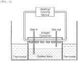
- the corrosion rates listed in Table 3, were results measured by the test apparatus illustrated in FIG. 1 .
- an airtight container was filled with distilled, water and a corrosive gas such as SO 2 , H 2 S, CO 2 , O 2 , or the like was continuously purged into the distilled water. Then a sample, having a size of 60mm ⁇ 20mm ⁇ 5mm, to measure a corrosion rate was polished with #600 sandpaper and located on top of the airtight container.
- a cover of the airtight container was provided with a gas inlet, an outlet, and a heating/cooling water circulation system. After being air-tightened, the airtight container was mounted in a thermostat and a temperature cycle of (50°C, 20 hours) ⁇ (25°C, 4 hours) was given for 100 days.
- a gas, introduced into the test apparatus, was a gas simulating the sulfide dew point corrosion environment of an upper deck of the crude oil tank, and has a composition below.
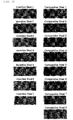
- FIG. 2 is an image of samples of the inventive steels 1 to 7 and the comparative steels 1 to 8 observed after a sulfide dew point corrosion test performed for 100 days.
- the inventive steels 1 to 7 in which the sensitivity index of sulfide dew corrosion satisfies the range of 1.7 or more to 2.5 or less proposed as Relational Expression 1 of the present disclosure, had a dense structure in which corrosion products had bright colors.
- the comparative steels 1 to 8 dark-colored corrosion products are visible to the naked eye.
- the sensitivity index of sulfide corrosion should be satisfied to prevent sulfide dew point corrosion.
- the sensitivity index is not satisfied, sufficient corrosion resistance is not secured to stably use a steel material in a corresponding environment, and thus life of a corresponding structure may not be secured.
Landscapes
- Chemical & Material Sciences (AREA)
- Engineering & Computer Science (AREA)
- Materials Engineering (AREA)
- Mechanical Engineering (AREA)
- Metallurgy (AREA)
- Organic Chemistry (AREA)
- Physics & Mathematics (AREA)
- Thermal Sciences (AREA)
- Crystallography & Structural Chemistry (AREA)
- Heat Treatment Of Steel (AREA)
Abstract
Description
- The present disclosure relates to a steel material, having excellent corrosion resistance for use in an oil tanker, a crude oil tank, and the like, and particularly, to a steel material having excellent corrosion resistance in a dew condensation environment containing a sulfide gas and a method for producing the steel material.
- Among various steels for use in ships, a steel material for use in a crude oil tank for an oil tanker may suffer from significantly serious corrosion damage due to an internal environment of the crude oil tank. In the crude oil tank, various types of corrosion occur due to volatile components in crude, or inert gas, sent into the tank to achieve explosion proofing of, mixed seawater, salt in oilfield brine, or dew condensation, caused by an internal temperature difference, and the like. Additionally, a corrosion rate is significantly higher than a corrosion rate in a typical brine environment.
- In a top plate of a crude tank, hydrogen sulfide gas, evaporated from crude, and gas such as CO2, SO2, O2, or the like in inert gas, introduced to achieve explosion proof, may react with dew condensation, formed on a surface of a steel material by a temperature difference, to contain a large amount of hydrogen sulfide and sulfur dioxide components. Accordingly, corrosion occurs. Corrosion caused by the dew condensation, i.e. condensed water, is similar to atmospheric corrosion of atmospheric corrosion resistant steel because of the corrosion at the thin water film, and moisture is periodically and repeatedly condensed and dried due to a daily temperature range. For this reason, the corrosion, caused by condensed water, may be separately classified as dew point corrosion.
- During the daytime, dew condensation does not occur on the deckhead of a crude oil transport ship, running while loaded with crude oil, because an internal temperature of the deckhead rises to about 50°C. During the nighttime, evaporated moisture forms on a lower portion of the deckhead because the internal temperature of the deckhead drops to about 25 degrees Celsius. In the case of a 300,000 ton crude oil transport ship, up to 30 tons of water may condense on an upper portion of a deckhead to cause corrosion. Therefore, corrosion, caused by the condensed water, is not negligible.
- In addition, carbon dioxide and sulfur dioxide, combustible gases, are injected into an empty space in a tank of a crude oil transport ship to prevent the explosion of a hull. Such gases are dissolved in moisture, together with sulfur and hydrogen sulfide, already contained in crude oil, to form an atmosphere proximate to corrosion caused by acidic condensed water when dew condensation occurs. Generally, as acidity is increased, an amount of H+ ions, participating in a corrosion reaction, is increased. Therefore, a corrosion rate may be further increased.
-
Patent Documents Patent Document 1 was designed without consideration of corrosion caused by hydrogen sulfide when crude coil contains the hydrogen sulfide, the steel material for ship is insufficient to be used in an actual crude oil tank. - (Patent Documents 1) Japanese Patent Publication Laid-Open
2000-017381 - An aspect of the present disclosure is to provide a steel material which may optimize steel components and may identify a relationship between components to secure improved corrosion resistance, even in a dew condensation environment, including sulfides and a method for producing the steel material.
- According to an aspect of the present disclosure, there is provided a steel material, having excellent corrosion resistance in a dew condensation environment containing a sulfide gas, comprising, by weight percent (wt%), 0.02 to 0.2% of carbon (C), 0.1 to 1.0% of silicon (Si), 0.2 to 2.0% of manganese (Mn), 0.03% or less of phosphorus (P), 0.03% or less of sulfur (S), 0.05 to 0.5% of copper (Cu), 0.05 to 0.5% of nickel (Ni), 0.02 to 0.5% of molybdenum (Mo), 0.1% or less of aluminum (Al), 0.05 to 0.5% of chromium (Cr), 0.001 to 0.01% of calcium (Ca), and the balance of iron (Fe) and inevitable impurities.
- A sensitivity index of sulfide dew point corrosion, given by
Relational Expression 1, is 1.7 or more to 2.5 or less
- According to another aspect of the present disclosure, there is provided a method for producing a steel material, having excellent corrosion resistance in a dew condensation environment containing a sulfide gas, by hot-rolling and cooling a slab comrpising, by weight percent (wt%), 0.02 to 0.2% of carbon (C), 0.1 to 1.0% of silicon (Si), 0.2 to 2.0% of manganese (Mn), 0.03% or less of phosphorus (P), 0.03% or less of sulfur (S), 0.05 to 0.5% of copper (Cu), 0.05 to 0.5% of nickel (Ni), 0.02 to 0.5% of molybdenum (Mo), 0.1% or less of aluminum (Al), 0.05 to 0.5% of chromium (Cr), 0.001 to 0.01% of calcium (Ca), and the balance of iron (Fe) and inevitable impurities,
- A sensitivity index of sulfide dew point corrosion, given by
Relational Expression 1, is 1.7 or more to 2.5 or less
wherein the cooling is performed at a cooling rate of 10°C/s or higher between a cooling start temperature, higher than or equal to Ar3 temperature, and cooling stop temperature of (Ae1-30°C) to 600°C. - As set forth above, according to an example embodiment in the present disclosure, steel components may be optimized to satisfy a sensitivity index of sulfide dew point corrosion. Thus, resistance against the sulfide dew point corrosion may be improved.
-
-
FIG. 1 illustrates a test apparatus for simulating a sulfide dew condensation test in the present disclosure. -
FIG. 2 is an image illustrating a result of a sulfide dew point corrosion test performed for 100 days according to an example embodiment in the present disclosure. - Hereinafter, the present disclosure will be described in detail.
- The present inventors have conducted researches to address the above-described issues of the related art. The inventors found that in order to improve resistance against corrosion in a dew condensation environment containing sulfide gas, a composition of each component needs to be appropriately controlled, as set forth below. In addition, the inventors found that that relationships between components such as Ca, S, Cr, Mo, Ni, Mn, and the like, affecting sensitivity of dew point corrosion, needs to be appropriately controlled. For these reasons, the inventors conceived the present invention.
- First, an alloy composition range of a steel material according to the present disclosure will be described in detail. The steel material comprises, by weight percent (wt%), 0.02 to 0.2% of carbon (C), 0.1 to 1.0% of silicon (Si), 0.2 to 2.0% of manganese (Mn), 0.03% or less of phosphorus (P), 0.03% or less of sulfur (S), 0.05 to 0.5% of copper (Cu), 0.05 to 0.5% of nickel (Ni), 0.02 to 0.5% of molybdenum (Mo), 0.1% or less of aluminum (Al), 0.05 to 0.5% of chromium (Cr), 0.001 to 0.01% of calcium (Ca), and a balance of iron (Fe) and inevitable impurities.
- Carbon (C) is an element added to improve strength. When a content of carbon (C) is increased, hardenability may be increased to improve strength. However, as the amount of added carbon is increased, general corrosion resistance is reduced. And since precipitation of carbide or the like is promoted, localized corrosion resistance is also affected. The content of carbon (C) should be decreased to improve the general corrosion resistance and the localized corrosion resistance. However, when the content of carbon (C) is less than 0.02 wt%, it is difficult to secure strength. When carbon (C) is more than 0.2 wt%, weldability is deteriorated to be inappropriate for, in detail, steel for welded structure. Therefore, carbon (C) has a range, in detail, from 0.02 to 0.2 wt%. Under a viewpoint of corrosion resistance, the content of carbon (C) may be set to, in detail, be 0.16 wt% or less and may be set to, in further detail, 0.14 wt% or less to improve casting cracking and to reduce a carbon equivalent.
- Silicon (Si) needs to be present in amount of 0.1 wt% or more to serve as a deoxidizer and to serve to increase strength of steel. In addition, since silicon (Si) contributes to improvement in general corrosion resistance, it is advantageous to increase the content of silicon (Si). However, when the content of silicon (Si) is greater than 1.0 wt%, toughness and weldability are deteriorated. And since it is difficult to detach a scale during rolling, the scale causes a surface defect. Therefore, the content of silicon (Si) is limited to, in detail, 0.1 to 1.0 wt%. In further detail, silicon (Si) is added in an amount of 0.2 wt% or more to improve corrosion resistance.
- Manganese (Mn) is an element effect in increasing the strength without reducing toughness. However, when an excessive amount of manganese (MN) is added, an electrochemical reaction rate of a steel surface may be increased during a corrosion reaction to reduce corrosion resistance. When manganese (Mn) is added in an amount of less than 0.2 wt%, it is difficult to secure durability of a structural steel. When the content of manganese (Mn) is increased, hardenability is increased to improve strength. However, when manganese (Mn) is added in an amount greater than 2.0 wt%, weldability and corrosion resistance are reduced. Therefore, the content of manganese (Mn) is set to be, in detail, 0.2 to 2.0 wt%.
- Phosphorus (P) is an impurity element. When the phosphorous (P) is added in an amount greater than 0.03 wt%, weldability is significantly reduced and toughness is deteriorated. Therefore, the content of phosphorous (P) is limited to, in detail, 0.03 wt% or less.
- Sulfur (S) is also an impurity element. When the content of sulfur (S) is greater than 0.03 wt%, ductility, impact toughness, and weldability of steel are deteriorated. Accordingly, the content of sulfur (S) is limited to, in detail, 0.03 wt% or less. Sulfur (S) is apt to react with manganese (Mn) to form an elongated inclusion like manganese sulfide (MnS), and voids, formed on both ends of the elongated inclusion, may be a starting point of localized corrosion. Therefore, the content of sulfur (S) is limited to, in further detail, 0.01 wt% or less.
- When copper (Cu) is contained in an amount of 0.05 wt% or more together with nickel (Ni), exudation of iron (Fe) is delayed, which is effective in improving general corrosion resistance and localized corrosion resistance. However, when the amount of copper (Cu) is greater than 0.5 wt%, copper (Cu) in a liquid state melts into a grain boundary during production of a slab. Thus, cracking occurs during hot working, which is called "hot shortness" phenomenon. Therefore, the content of copper (Cu) is set to, in detail, be 0.05 to 0.5 wt%. Since surface cracking, occurring during production of the slab, interact with the contents of carbon (C), nickel (Ni), and manganese (Mn), a frequency of occurrence of the surface cracking may vary, depending on the content of each element, but the content of copper (Cu) is set to, in further detail, be 0.5 wt% or less.
- Similarly to the case of copper (Cu), when nickel (Ni) is contained in an amount of 0.05 wt% or more, it is effective in improving general corrosion resistance and localized corrosion resistance. In addition, when nickel (Ni) is added together with copper (Cu), nickel (Ni) reacts with copper (Cu) in such a manner that formation of a copper (Cu) phase is suppressed to prevent hot shortness from occurring. Nickel (Ni) is also an element effective in improving toughness of a base material. However, since nickel (Ni) is an expensive element, the addition of nickel (Ni) in an amount of 0.5 wt% or more is disadvantageous in terms of economical efficiency and weldability. Therefore, the content of nickel (Ni) is set to, in detail, be 0.05 to 0.5 wt%.
- Since an influence of nickel (Ni) on improvement of corrosion resistance is not higher than an influence of copper (Cu), the content of nickel (Ni) is greater than or equal to the content of copper (Cu), in detail, 1.5 times or less the content of copper (Cu) to suppress surface cracking caused by addition of copper (Cu), rather than containing a great amount of nickel (Ni) to improve corrosion resistance. The content of nickel (Ni) is limited to, in further detail, 0.3 wt% or less.
- Molybdenum (Mo) is an element contributing to improvement of corrosion resistance and strength and should be added in an amount of 0.02 wt% or more to achieve such an effect. However, molybdenum (Mo) should be dissolved in steel to improve corrosion resistance. For example, the dissolved molybdenum (Mo) improves the corrosion resistance to the condensed water containing hydrogen sulfide. However, molybdenum (Mo), contained in an amount greater than a dissolution limit, may reacts with sulfur (S) in such a manner Mo2S is formed to reduce corrosion resistance. Therefore, when an excessive amount of molybdenum (Mo) is added, corrosion resistance against condensed water, containing hydrogen sulfide, may be reduced. Hence, an upper limit thereof is, in detail, 0.5 wt%. In addition, a precipitate of molybdenum (Mo) serves to improve strength, but coarsely precipitated molybdenum (Mo) may cause localized corrosion of the steel. Therefore, molybdenum (Mo) is added in an amount of, in further detail, 0.1 wt% or less.
- Aluminum (Al) is an element, added for deoxidation, and reacts with nitrogen (N) in the steel in such a manner that an aluminum nitride (AlN) is formed and austenite grains are refined to improve toughness. However, when aluminum (Al) is contained in an amount greater than 0.1 wt%, an inclusion is formed in a coarse oxide during a steelmaking process and a stretched inclusion, crushed and elongated during rolling, is formed according to aluminum oxide-based characteristics. Since the formation of such an elongated inclusion promotes the formation of a void around the inclusion and such a void serves as a starting point for localized corrosion, the elongated inclusion serves to reduce the localized corrosion resistance. Therefore, the content of aluminum (Al) is set to, in detail, be 0.1 wt% or less. Since deoxidation effect may be obtained by another deoxidizing element such as silicon (Si) or the like even when aluminum (Al) is added, a lower limit of aluminum (Al) is not limited. However, in detail, at least 0.001 wt% or more of aluminum (Al) may be added to expect a deoxidation effect achieved by aluminum (Al).
- Chromium (Cr) is an element which increases the corrosion resistance by forming a chrome-containing oxide layer on a surface of the steel in a corrosive environment. Chromium (Cr) should be contained in an amount of 0.05 wt% or more to exhibit a corrosion resistance effect depending on addition of chromium (Cr). However, when chromium (Cr) is contained in an amount greater than 0.5 wt%, toughness and weldability are adversely affected. Therefore, the content of chromium (Cr) is set to, in detail, be 0.05 to 0.5 wt%.
- Calcium (Ca) reacts with aluminum (Al), silicon (Si), and oxygen (O) in a molten steel to form a composite oxide and then reacts with sulfur (S) to form calcium sulfide (CaS). Such a calcium sulfide (CaS) inclusion is dissolved in water in a dew condensation environment to increase pH of the surface of the steel. Thus, formation of a stable phase is promoted under suppress of an electrochemical reaction of the steel to improve corrosion resistance characteristics. To improve the corrosion resistance, calcium (Ca) should be added in an amount of at least 0.001 wt%. However, when the content of calcium (Ca) is greater than 0.01 wt%, refractories may be melted during a steelmaking process. Therefore, the content of Ca is set to, in detail, be 0.001 to 0.01 wt%. Additionally, calcium (Ca) is added in an amount of, in further detail, 0.002 wt% or more to secure a sulfide dew point corrosion sensitivity index.
- In addition to the above components, the balance includes iron (Fe) and inevitable impurities. However, the addition of other alloying elements is not excluded, without departing from the scope of the present disclosure.
- In the steel material of the present disclosure, the sulfide condensation corrosion sensitivity index, defined as
Relational Expression 1, satisfies, in detail, 1.7 to 2.3.
- The above Ca, Cr, Mo, Cu, Ni, and Mn are components affecting a corrosion resistance effect in a sulfide dew condensation environment depending on amounts of addition thereof. An influence of each of these components on the corrosion resistance was quantitatively derived, and a relationship between the components was expressed by
Relational Expression 1. When the sensitivity index of sulfide dew point corrosion, defined asRelational Expression 1, is 1.7 to 2.5, improved corrosion resistance may be secured in a corresponding environment. - The steel of the present disclosure, having the advantageous composition, may be easily produced using knowledge in the art by a person of ordinary skill in the art without excessively repeated tests. A producing method, more advantageous than the method found by the present inventors, for example, a method for producing the steel material is proposed in the present disclosure.
- The method for producing a steel material according to the present disclosure is a method for producing a steel material through conventional hot rolling and cooling, and is characterized in that the cooling is performed at a cooling rate of 10°C/sec or less in such a manner that cooling starting temperature is Ar3 temperature or higher and cooling stop temperature ranges from (Ae1-30°C) to 600°C. Hereinafter, cooling conditions of the present disclosure will be described.
- According to a result of tests performed by the present inventors, when molybdenum (Mo), added to achieve the advantageous effect, forms a great amount of precipitate, the added molybdenum (Mo) has an adverse influence on general corrosion, localized corrosion, or the like. Meanwhile, when an excessive amount of molybdenum (Mo) is dissolved, molybdenum (Mo) has an adverse influence on corrosion resistance in an environment containing hydrogen sulfide. Therefore, it is necessary to appropriately control a ratio of molybdenum (Mo), forming the precipitate, and the dissolved molybdenum (Mo). Since molybdenum (Mo) tends to form precipitates at temperature between 700 and 550°C, a portion of the section needs to be rapidly cooled to prevent that molybdenum (Mo) forms a precipitate and the other portions of the section needs to be slowly cooled to prevent that molybdenum (Mo) is excessively dissolved.
- When cooling is started at temperature lower than or Ar3 temperature, copper (Cu) is segregated to pearlite to accelerate corrosion caused by a galvanic pair of the pearlite and ferrite. Accordingly, the cooling needs to be started at temperature, higher than or equal to the Ar3 temperature, and needs to be performed to a temperature of (Ael-30°C) or lower at which precipitates such as molybdenum (Mo) are appropriately formed without forming pearlite. When the cooling is performed to significantly low temperature, molybdenum (Mo) is not appropriately precipitated and is excessively dissolved. Therefore, molybdenum (Mo) may bond to sulfur (S) at a condensed water atmosphere, containing hydrogen sulfide, to form Mo2S and may deteriorate corrosion resistance of the steel material. As a result, the cooling needs to be finished at temperature of 600°C or higher.
- Since time, taken to pass through a temperature range in which a precipitate of molybdenum (Mo) is easily formed, is increased when the cooling rate is low, the precipitate may be excessively formed. Therefore, the cooling rate needs to be 10°C/s or higher. Even if the cooling rate is high, there is no problem in achieving objects of the present disclosure. Accordingly, it is unnecessary to determine an upper limit of the cooling rate. However, since there may be a limitation in capability of cooling equipment, the upper limit may be determined to be 50°C/s in consideration of the limitation in capability to apply a significantly high cooling rate.
- Hereinafter, an example embodiment in the present disclosure will be described in detail. However, the present disclosure is not limited to the example embodiment described herein.
- A steel slab was produced using continuous casting after preparing molten steel having a composition (weight percent (wt%), the balance including iron (Fe) and inevitable impurities) listed in Table 1. The produced steel slab was hot-rolled under normal conditions and then cooled under conditions in Table 2.
Table 1 Steel No. C Si Mn P S Ni Mo Al Cu Cr Ca IS 1 0.06 0.45 0.9 0.015 0.003 0.35 0.05 0.025 0.25 0.2 0.004 IS 2 0.08 0.61 1.1 0.02 0.002 0.26 0.03 0.03 0.22 0.15 0.004 IS 3 0.09 0.81 1.2 0.02 0.004 0.4 0.12 0.029 0.1 0.09 0.008 IS 4 0.04 0.75 0.9 0.019 0.003 0.31 0.04 0.034 0.14 0.12 0.007 IS 5 0.12 0.51 0.8 0.012 0.003 0.4 0.05 0.031 0.3 0.11 0.006 IS 6 0.16 0.31 1.4 0.022 0.006 0.29 0.03 0.027 0.19 0.3 0.002 IS 7 0.15 0.5 0.7 0.011 0.005 0.24 0.06 0.021 0.21 0.25 0.003 CS 10.07 0.45 0.9 0.012 0.004 0.21 0 0.035 0.15 0.15 0.002 CS 20.11 0.52 1.2 0.018 0.004 0.22 0.02 0.031 0.16 '0.21 0.001 CS 30.09 0.49 0.8 0.017 0.004 0.16 0.04 0.029 0.12 0.2 0.003 CS 40.1 0.51 1.1 0.016 0.005 0.19 0.05 0.034 0.14 0.25 0.001 CS 50.06 0.68 1.5 0.015 0.003 0.45 0.02 0.036 0 0.2 0.004 CS 60.1 0.56 1.2 0.018 0.005 0.4 0.05 0.036 0.3 0 0.006 CS 70.1 0.6 1.3 0.018 0.008 0.15 0.2 0.029 0.1 0.35 0.001 CS 80.08 0.55 1.2 0.013 0.007 0.21 0.17 0.027 0.12 0.31 0.002 *IS: Inventive Steel
*CS: Comparative SteelTable 2 Steel No. Ar3 (°C) Cooling Starting Temperature (°C) Cooling Ending Temperature (°C) Cooling Rate (°C/s) IS 1 794 815 658 17.3 IS 2 780 812 634 19.7 IS 3 757 805 647 17.5 IS 4 807 829 622 21.8 IS 5 781 819 634 20.1 IS 6 728 778 651 14.6 IS 7 788 809 647 17.5 CS 1806 820 644 19.2 CS 2766 791 618 18.5 CS 3807 834 634 20.9 CS 4776 807 627 19.8 CS 5748 798 613 20.1 CS 6757 789 618 18.5 CS 7750 781 616 17.9 CS 8763 777 620 17.1 *IS: Inventive Steel
*CS: Comparative Steel - As can be seen from the Table 1, inventive steels refer to steel sheets having compositions satisfying a composition range defined in the present disclosure. However,
comparative steels Comparative steels Relational Expression 1, does not satisfy a required range because the sensitivity index is less than 1.7 or more than 2.5, as described later. Such components of the comparative steels are significantly reduced in corrosion resistance than those of the inventive steels. Accordingly, since corrosion of the steel material cannot be prevented in the sulfide dew point corrosion environment, the corrosion resistance may be reduced and a replacement cycle may be increased. - Table 3 below lists measurement results of sensitivity indices of sulfide dew point corrosion and corrosion rates of inventive steels and comparative steels. The corrosion rates, listed in Table 3, were results measured by the test apparatus illustrated in
FIG. 1 . For example, as illustrated inFIG. 1 , in order to simulate the sulfide dew condensation environment, an airtight container was filled with distilled, water and a corrosive gas such as SO2, H2S, CO2, O2, or the like was continuously purged into the distilled water. Then a sample, having a size of 60mm × 20mm × 5mm, to measure a corrosion rate was polished with #600 sandpaper and located on top of the airtight container. A cover of the airtight container was provided with a gas inlet, an outlet, and a heating/cooling water circulation system. After being air-tightened, the airtight container was mounted in a thermostat and a temperature cycle of (50°C, 20 hours) → (25°C, 4 hours) was given for 100 days. A gas, introduced into the test apparatus, was a gas simulating the sulfide dew point corrosion environment of an upper deck of the crude oil tank, and has a composition below. - After a corrosion test for 100 days, a derusting treatment was performed in a corrosion product removal solution. Mass loss of each sample was divided by a surface area of an initial sample. For relative comparison, the corrosion rate of the
comparative steel 1 was set to 100, and relative corrosion rates are listed in Table 3.Table 3 Steel No. Sensitivity Index of Sulfide Dew point corrosion Relative Corrosion Rate IS 1 2.23 38 IS 2 1.88 49 IS 3 1.97 42 IS 4 1.91 45 IS 5 2.25 34 IS 6 1.78 57 IS 7 2.16 37 CS 11.01 100 CS 21.21 95 CS 31.54 90 CS 41.55 90 CS 51.35 88 CS 61.18 85 CS 72.70 69 CS 82.53 65 *IS: Inventive Steel
*CS: Comparative Steel - As can be seen from Table 2, when the corrosion resistance element such as Mo, Cu, Cr, or the like is not added at all or is insufficiently added and the sensitivity index of sulfide dew condensation does not satisfy a range of more than 1.7 to less than 2.3 proposed in the present disclosure, a relative corrosion rate is at most twice as high as that of the inventive steel. Such a phenomenon occurred in all comparative steels although the degree thereof was slightly different, which is determined to result from the fact that the sensitivity index of sulfide dew condensation, proposed in the present disclosure, was not satisfied.
-
FIG. 2 is an image of samples of theinventive steels 1 to 7 and thecomparative steels 1 to 8 observed after a sulfide dew point corrosion test performed for 100 days. As described above, theinventive steels 1 to 7, in which the sensitivity index of sulfide dew corrosion satisfies the range of 1.7 or more to 2.5 or less proposed asRelational Expression 1 of the present disclosure, had a dense structure in which corrosion products had bright colors. In the case of thecomparative steels 1 to 8, dark-colored corrosion products are visible to the naked eye. - As described above, as illustrated in Table 3 and
FIG. 2 , the sensitivity index of sulfide corrosion, proposed in the present disclosure, should be satisfied to prevent sulfide dew point corrosion. When the sensitivity index is not satisfied, sufficient corrosion resistance is not secured to stably use a steel material in a corresponding environment, and thus life of a corresponding structure may not be secured.
Claims (6)
- A steel material, having excellent corrosion resistance in a dew condensation environment containing a sulfide gas, comprising, by weight percent (wt%), 0.02 to 0.2% of carbon (C), 0.1 to 1.0% of silicon (Si), 0.2 to 2.0% of manganese (Mn), 0.03% or less of phosphorus (P), 0.03% or less of sulfur (S), 0.05 to 0.5% of copper (Cu), 0.05 to 0.5% of nickel (Ni), 0.02 to 0.5% of molybdenum (Mo), 0.1% or less of aluminum (Al), 0.05 to 0.5% of chromium (Cr), 0.001 to 0.01% of calcium (Ca), and the balance of iron (Fe) and inevitable impurities,
wherein a sensitivity index of sulfide dew point corrosion, given by Relational Expression 1, is 1.7 or more to 2.5 or less
- The steel material of claim 1, wherein a content of the Ni is greater than or equal to a content of the Cu, and is 1.5 times or less the content of the Cu.
- The steel material of claim 1, wherein the Cu is 0.002 to 0.01%.
- A method for producing a steel material, having excellent corrosion resistance in a dew condensation environment containing a sulfide gas, by hot-rolling and cooling a slab comprising, by weight percent (wt%), 0.02 to 0.2% of carbon (C), 0.1 to 1.0% of silicon (Si), 0.2 to 2.0% of manganese (Mn), 0.03% or less of phosphorus (P), 0.03% or less of sulfur (S), 0.05 to 0.5% of copper (Cu), 0.05 to 0.5% of nickel (Ni), 0.02 to 0.5% of molybdenum (Mo), 0.1% or less of aluminum (Al), 0.05 to 0.5% of chromium (Cr), 0.001 to 0.01% of calcium (Ca), and the balance of iron (Fe) and inevitable impurities,
wherein a sensitivity index of sulfide dew point corrosion, given by Relational Expression 1, is 1.7 or more to 2.5 or less where Ca, S, Cr, Mo, Cu, Ni, and Mn denote contents (wt%) of corresponding elements, andwherein the cooling is performed at a cooling rate of 10°C/s or higher between cooling start temperature, higher than or equal to Ar3 temperature, and cooling stop temperature of (Ae1-30°C) to 600°C.
 - The method of claim 4, wherein a content of the Ni is greater than or equal to a content of the Cu, and is 1.5 times or less the content of the Cu.
- The method of claim 4, wherein the Cu is 0.002 to 0.01%.
Applications Claiming Priority (2)
| Application Number | Priority Date | Filing Date | Title |
|---|---|---|---|
| KR1020160177202A KR101889195B1 (en) | 2016-12-22 | 2016-12-22 | Steel having excellent corrosion resitance in condensed water containing surfide and method for manufacturing the same |
| PCT/KR2017/015294 WO2018117715A1 (en) | 2016-12-22 | 2017-12-21 | Steel material having excellent corrosion resistance in dew condensation environment containing sulfide and method for producing same |
Publications (3)
| Publication Number | Publication Date |
|---|---|
| EP3561126A1 true EP3561126A1 (en) | 2019-10-30 |
| EP3561126A4 EP3561126A4 (en) | 2019-12-25 |
| EP3561126B1 EP3561126B1 (en) | 2023-08-30 |
Family
ID=62626952
Family Applications (1)
| Application Number | Title | Priority Date | Filing Date |
|---|---|---|---|
| EP17885245.5A Active EP3561126B1 (en) | 2016-12-22 | 2017-12-21 | Steel material having excellent corrosion resistance in dew condensation environment containing sulfide and method for producing same |
Country Status (6)
| Country | Link |
|---|---|
| US (1) | US20200087766A1 (en) |
| EP (1) | EP3561126B1 (en) |
| JP (1) | JP6818145B2 (en) |
| KR (1) | KR101889195B1 (en) |
| CN (2) | CN110088345A (en) |
| WO (1) | WO2018117715A1 (en) |
Families Citing this family (1)
| Publication number | Priority date | Publication date | Assignee | Title |
|---|---|---|---|---|
| CN114428051A (en) * | 2020-10-29 | 2022-05-03 | 中国石油化工股份有限公司 | Dew point corrosion assessment device with controllable condensation temperature |
Family Cites Families (14)
| Publication number | Priority date | Publication date | Assignee | Title |
|---|---|---|---|---|
| JPS53115611A (en) * | 1977-03-19 | 1978-10-09 | Nippon Steel Corp | Method for low-alloyed steel of high carbon content for welding use excellent in weld crack resistance |
| JPH07188838A (en) * | 1993-12-27 | 1995-07-25 | Nippon Steel Corp | Thick steel plate for pressure vessels with excellent SOHIC resistance in wet hydrogen sulfide environment |
| JP3860666B2 (en) | 1998-07-03 | 2006-12-20 | 新日本製鐵株式会社 | Corrosion resistant steel for cargo oil tanks |
| JP3570376B2 (en) * | 2000-12-04 | 2004-09-29 | Jfeスチール株式会社 | Steel material excellent in corrosion resistance of crude oil tank and its manufacturing method |
| KR20060012952A (en) | 2004-08-05 | 2006-02-09 | 엔에이치엔(주) | Internet game service system and method using personalized victory sound effect |
| JP5014831B2 (en) * | 2007-02-22 | 2012-08-29 | 新日本製鐵株式会社 | ERW steel pipe for expanded oil well with excellent pipe expansion performance and corrosion resistance and method for producing the same |
| KR101069981B1 (en) * | 2008-12-11 | 2011-10-04 | 주식회사 포스코 | Manufacturing method for steel with excellent corrosion resistance at condensed water containing hydrogen sulfide |
| JP5526859B2 (en) * | 2009-02-26 | 2014-06-18 | Jfeスチール株式会社 | Steel for crude oil tankers |
| JP5662894B2 (en) * | 2011-07-27 | 2015-02-04 | 株式会社神戸製鋼所 | Steel material for the upper deck of crude oil tankers with excellent corrosion resistance or cargo for bulk carriers |
| JP2014201759A (en) | 2013-04-01 | 2014-10-27 | Jfeスチール株式会社 | Steel material for crude oil tank with excellent corrosion resistance, and crude oil tank |
| CN103286127B (en) * | 2013-06-14 | 2015-06-24 | 首钢总公司 | Method for manufacturing anticorrosion steel plate for upper deck on crude oil tanker oil cargo tank and steel plate |
| JP6048385B2 (en) * | 2013-12-12 | 2016-12-21 | Jfeスチール株式会社 | Steel for crude oil tanks and crude oil tanks with excellent corrosion resistance |
| CN106086641B (en) * | 2016-06-23 | 2017-08-22 | 江阴兴澄特种钢铁有限公司 | A kind of super-huge petroleum storage tank high-strength steel of hydrogen sulfide corrosion resistant and its manufacture method |
| KR101696157B1 (en) * | 2016-08-01 | 2017-01-13 | 주식회사 포스코 | Hot rolled steel plate having excellent sulfide stress cracking resistance and method for manufacturing the same |
-
2016
- 2016-12-22 KR KR1020160177202A patent/KR101889195B1/en active Active
-
2017
- 2017-12-21 WO PCT/KR2017/015294 patent/WO2018117715A1/en not_active Ceased
- 2017-12-21 US US16/471,271 patent/US20200087766A1/en not_active Abandoned
- 2017-12-21 CN CN201780078973.9A patent/CN110088345A/en active Pending
- 2017-12-21 EP EP17885245.5A patent/EP3561126B1/en active Active
- 2017-12-21 CN CN202512008200.2A patent/CN121896547A/en active Pending
- 2017-12-21 JP JP2019528916A patent/JP6818145B2/en active Active
Also Published As
| Publication number | Publication date |
|---|---|
| WO2018117715A1 (en) | 2018-06-28 |
| JP2020509164A (en) | 2020-03-26 |
| CN121896547A (en) | 2026-04-21 |
| EP3561126B1 (en) | 2023-08-30 |
| US20200087766A1 (en) | 2020-03-19 |
| CN110088345A (en) | 2019-08-02 |
| EP3561126A4 (en) | 2019-12-25 |
| JP6818145B2 (en) | 2021-01-20 |
| KR101889195B1 (en) | 2018-08-16 |
| KR20180073414A (en) | 2018-07-02 |
Similar Documents
| Publication | Publication Date | Title |
|---|---|---|
| CN114761595B (en) | Steel plate and manufacturing method thereof | |
| US11208703B2 (en) | Nickel-containing steel for low temperature service and low-temperature tank | |
| KR20160049023A (en) | Corrosion resistant steel for crude oil tank, manufacturing method therefor, and crude oil tank | |
| CN109642287B (en) | Sulfuric acid dew point corrosion resistant steel | |
| WO2020091023A1 (en) | Corrosion-resistant steel for holds of coal carrying vessels or ore/coal carrying vessels, and hold | |
| CN115667563B (en) | Precipitation hardening martensitic stainless steel sheet excellent in fatigue resistance | |
| EP3722448B1 (en) | High-mn steel and method for manufacturing same | |
| KR102884405B1 (en) | Steel plate and method for manufacturing the same | |
| CN110408842B (en) | Duplex stainless steel with excellent low temperature toughness | |
| US20080112840A1 (en) | Duplex Stainless Steel Having Excellent Corrosion Resistance with Low Nickel | |
| EP3872212B1 (en) | Cryogenic austenitic high-manganese steel having excellent corrosion resistance, and manufacturing method therefor | |
| EP3561126B1 (en) | Steel material having excellent corrosion resistance in dew condensation environment containing sulfide and method for producing same | |
| KR102801931B1 (en) | Steel sheet and its manufacturing method | |
| CN118434899A (en) | Steel plate and method for manufacturing the same | |
| EP2578715B1 (en) | Structural stainless steel sheet having excellent corrosion resistance in welded part, and method for producing same | |
| JP2002173736A (en) | Steel material excellent in corrosion resistance of crude oil tank and production method thereof | |
| EP3878996A1 (en) | High strength steel plate for structure with good seawater corrosion resistant property and method of manufacturing same | |
| EP3978642A1 (en) | Austenitic stainless steel with excellent corrosion resistance of welded part | |
| EP3124639B1 (en) | Steel sheet for high-strength line pipe having excellent low temperature toughness, and steel tube for high-strength line pipe | |
| US12221680B2 (en) | Cryogenic austenitic high-manganese steel having excellent corrosion resistance, and manufacturing method therefor | |
| KR101069981B1 (en) | Manufacturing method for steel with excellent corrosion resistance at condensed water containing hydrogen sulfide | |
| JP7815523B1 (en) | Ultra-low magnetic permeability stainless steel | |
| TWI908203B (en) | Steel Plate and its Manufacturing Method | |
| EP4640902A1 (en) | Steel plate and method for manufacturing same | |
| RU2496906C2 (en) | Low-carbon steel, and rolled products from low-carbon steel of increased stability to hydrogen cracking and increased cold resistance |
Legal Events
| Date | Code | Title | Description |
|---|---|---|---|
| STAA | Information on the status of an ep patent application or granted ep patent |
Free format text: STATUS: THE INTERNATIONAL PUBLICATION HAS BEEN MADE |
|
| PUAI | Public reference made under article 153(3) epc to a published international application that has entered the european phase |
Free format text: ORIGINAL CODE: 0009012 |
|
| STAA | Information on the status of an ep patent application or granted ep patent |
Free format text: STATUS: REQUEST FOR EXAMINATION WAS MADE |
|
| 17P | Request for examination filed |
Effective date: 20190605 |
|
| AK | Designated contracting states |
Kind code of ref document: A1 Designated state(s): AL AT BE BG CH CY CZ DE DK EE ES FI FR GB GR HR HU IE IS IT LI LT LU LV MC MK MT NL NO PL PT RO RS SE SI SK SM TR |
|
| AX | Request for extension of the european patent |
Extension state: BA ME |
|
| A4 | Supplementary search report drawn up and despatched |
Effective date: 20191125 |
|
| RIC1 | Information provided on ipc code assigned before grant |
Ipc: C21D 8/02 20060101ALI20191115BHEP Ipc: C22C 38/02 20060101ALI20191115BHEP Ipc: C21D 9/46 20060101ALI20191115BHEP Ipc: C22C 38/42 20060101AFI20191115BHEP Ipc: C22C 38/58 20060101ALI20191115BHEP Ipc: C22C 38/06 20060101ALI20191115BHEP Ipc: C22C 38/44 20060101ALI20191115BHEP Ipc: C22C 38/04 20060101ALI20191115BHEP Ipc: C22C 38/00 20060101ALI20191115BHEP |
|
| DAV | Request for validation of the european patent (deleted) | ||
| DAX | Request for extension of the european patent (deleted) | ||
| STAA | Information on the status of an ep patent application or granted ep patent |
Free format text: STATUS: EXAMINATION IS IN PROGRESS |
|
| 17Q | First examination report despatched |
Effective date: 20210120 |
|
| RAP3 | Party data changed (applicant data changed or rights of an application transferred) |
Owner name: POSCO HOLDINGS INC. |
|
| RAP1 | Party data changed (applicant data changed or rights of an application transferred) |
Owner name: POSCO CO., LTD |
|
| GRAP | Despatch of communication of intention to grant a patent |
Free format text: ORIGINAL CODE: EPIDOSNIGR1 |
|
| STAA | Information on the status of an ep patent application or granted ep patent |
Free format text: STATUS: GRANT OF PATENT IS INTENDED |
|
| INTG | Intention to grant announced |
Effective date: 20230321 |
|
| RIN1 | Information on inventor provided before grant (corrected) |
Inventor name: UM, KYUNG-KEUN Inventor name: PARK, JIN-HO |
|
| GRAS | Grant fee paid |
Free format text: ORIGINAL CODE: EPIDOSNIGR3 |
|
| GRAA | (expected) grant |
Free format text: ORIGINAL CODE: 0009210 |
|
| STAA | Information on the status of an ep patent application or granted ep patent |
Free format text: STATUS: THE PATENT HAS BEEN GRANTED |
|
| AK | Designated contracting states |
Kind code of ref document: B1 Designated state(s): AL AT BE BG CH CY CZ DE DK EE ES FI FR GB GR HR HU IE IS IT LI LT LU LV MC MK MT NL NO PL PT RO RS SE SI SK SM TR |
|
| REG | Reference to a national code |
Ref country code: GB Ref legal event code: FG4D |
|
| REG | Reference to a national code |
Ref country code: CH Ref legal event code: EP |
|
| REG | Reference to a national code |
Ref country code: DE Ref legal event code: R096 Ref document number: 602017073570 Country of ref document: DE |
|
| REG | Reference to a national code |
Ref country code: IE Ref legal event code: FG4D |
|
| REG | Reference to a national code |
Ref country code: LT Ref legal event code: MG9D |
|
| REG | Reference to a national code |
Ref country code: NL Ref legal event code: MP Effective date: 20230830 |
|
| REG | Reference to a national code |
Ref country code: NO Ref legal event code: T2 Effective date: 20230830 |
|
| REG | Reference to a national code |
Ref country code: AT Ref legal event code: MK05 Ref document number: 1605537 Country of ref document: AT Kind code of ref document: T Effective date: 20230830 |
|
| PG25 | Lapsed in a contracting state [announced via postgrant information from national office to epo] |
Ref country code: GR Free format text: LAPSE BECAUSE OF FAILURE TO SUBMIT A TRANSLATION OF THE DESCRIPTION OR TO PAY THE FEE WITHIN THE PRESCRIBED TIME-LIMIT Effective date: 20231201 |
|
| PG25 | Lapsed in a contracting state [announced via postgrant information from national office to epo] |
Ref country code: IS Free format text: LAPSE BECAUSE OF FAILURE TO SUBMIT A TRANSLATION OF THE DESCRIPTION OR TO PAY THE FEE WITHIN THE PRESCRIBED TIME-LIMIT Effective date: 20231230 |
|
| PG25 | Lapsed in a contracting state [announced via postgrant information from national office to epo] |
Ref country code: SE Free format text: LAPSE BECAUSE OF FAILURE TO SUBMIT A TRANSLATION OF THE DESCRIPTION OR TO PAY THE FEE WITHIN THE PRESCRIBED TIME-LIMIT Effective date: 20230830 Ref country code: RS Free format text: LAPSE BECAUSE OF FAILURE TO SUBMIT A TRANSLATION OF THE DESCRIPTION OR TO PAY THE FEE WITHIN THE PRESCRIBED TIME-LIMIT Effective date: 20230830 Ref country code: LV Free format text: LAPSE BECAUSE OF FAILURE TO SUBMIT A TRANSLATION OF THE DESCRIPTION OR TO PAY THE FEE WITHIN THE PRESCRIBED TIME-LIMIT Effective date: 20230830 Ref country code: LT Free format text: LAPSE BECAUSE OF FAILURE TO SUBMIT A TRANSLATION OF THE DESCRIPTION OR TO PAY THE FEE WITHIN THE PRESCRIBED TIME-LIMIT Effective date: 20230830 Ref country code: IS Free format text: LAPSE BECAUSE OF FAILURE TO SUBMIT A TRANSLATION OF THE DESCRIPTION OR TO PAY THE FEE WITHIN THE PRESCRIBED TIME-LIMIT Effective date: 20231230 Ref country code: HR Free format text: LAPSE BECAUSE OF FAILURE TO SUBMIT A TRANSLATION OF THE DESCRIPTION OR TO PAY THE FEE WITHIN THE PRESCRIBED TIME-LIMIT Effective date: 20230830 Ref country code: GR Free format text: LAPSE BECAUSE OF FAILURE TO SUBMIT A TRANSLATION OF THE DESCRIPTION OR TO PAY THE FEE WITHIN THE PRESCRIBED TIME-LIMIT Effective date: 20231201 Ref country code: FI Free format text: LAPSE BECAUSE OF FAILURE TO SUBMIT A TRANSLATION OF THE DESCRIPTION OR TO PAY THE FEE WITHIN THE PRESCRIBED TIME-LIMIT Effective date: 20230830 Ref country code: AT Free format text: LAPSE BECAUSE OF FAILURE TO SUBMIT A TRANSLATION OF THE DESCRIPTION OR TO PAY THE FEE WITHIN THE PRESCRIBED TIME-LIMIT Effective date: 20230830 |
|
| PG25 | Lapsed in a contracting state [announced via postgrant information from national office to epo] |
Ref country code: PL Free format text: LAPSE BECAUSE OF FAILURE TO SUBMIT A TRANSLATION OF THE DESCRIPTION OR TO PAY THE FEE WITHIN THE PRESCRIBED TIME-LIMIT Effective date: 20230830 Ref country code: NL Free format text: LAPSE BECAUSE OF FAILURE TO SUBMIT A TRANSLATION OF THE DESCRIPTION OR TO PAY THE FEE WITHIN THE PRESCRIBED TIME-LIMIT Effective date: 20230830 |
|
| PG25 | Lapsed in a contracting state [announced via postgrant information from national office to epo] |
Ref country code: ES Free format text: LAPSE BECAUSE OF FAILURE TO SUBMIT A TRANSLATION OF THE DESCRIPTION OR TO PAY THE FEE WITHIN THE PRESCRIBED TIME-LIMIT Effective date: 20230830 |
|
| PG25 | Lapsed in a contracting state [announced via postgrant information from national office to epo] |
Ref country code: SM Free format text: LAPSE BECAUSE OF FAILURE TO SUBMIT A TRANSLATION OF THE DESCRIPTION OR TO PAY THE FEE WITHIN THE PRESCRIBED TIME-LIMIT Effective date: 20230830 Ref country code: RO Free format text: LAPSE BECAUSE OF FAILURE TO SUBMIT A TRANSLATION OF THE DESCRIPTION OR TO PAY THE FEE WITHIN THE PRESCRIBED TIME-LIMIT Effective date: 20230830 Ref country code: ES Free format text: LAPSE BECAUSE OF FAILURE TO SUBMIT A TRANSLATION OF THE DESCRIPTION OR TO PAY THE FEE WITHIN THE PRESCRIBED TIME-LIMIT Effective date: 20230830 Ref country code: EE Free format text: LAPSE BECAUSE OF FAILURE TO SUBMIT A TRANSLATION OF THE DESCRIPTION OR TO PAY THE FEE WITHIN THE PRESCRIBED TIME-LIMIT Effective date: 20230830 Ref country code: DK Free format text: LAPSE BECAUSE OF FAILURE TO SUBMIT A TRANSLATION OF THE DESCRIPTION OR TO PAY THE FEE WITHIN THE PRESCRIBED TIME-LIMIT Effective date: 20230830 Ref country code: CZ Free format text: LAPSE BECAUSE OF FAILURE TO SUBMIT A TRANSLATION OF THE DESCRIPTION OR TO PAY THE FEE WITHIN THE PRESCRIBED TIME-LIMIT Effective date: 20230830 Ref country code: SK Free format text: LAPSE BECAUSE OF FAILURE TO SUBMIT A TRANSLATION OF THE DESCRIPTION OR TO PAY THE FEE WITHIN THE PRESCRIBED TIME-LIMIT Effective date: 20230830 Ref country code: PT Free format text: LAPSE BECAUSE OF FAILURE TO SUBMIT A TRANSLATION OF THE DESCRIPTION OR TO PAY THE FEE WITHIN THE PRESCRIBED TIME-LIMIT Effective date: 20240102 |
|
| PG25 | Lapsed in a contracting state [announced via postgrant information from national office to epo] |
Ref country code: IT Free format text: LAPSE BECAUSE OF FAILURE TO SUBMIT A TRANSLATION OF THE DESCRIPTION OR TO PAY THE FEE WITHIN THE PRESCRIBED TIME-LIMIT Effective date: 20230830 |
|
| REG | Reference to a national code |
Ref country code: DE Ref legal event code: R097 Ref document number: 602017073570 Country of ref document: DE |
|
| PLBE | No opposition filed within time limit |
Free format text: ORIGINAL CODE: 0009261 |
|
| STAA | Information on the status of an ep patent application or granted ep patent |
Free format text: STATUS: NO OPPOSITION FILED WITHIN TIME LIMIT |
|
| PG25 | Lapsed in a contracting state [announced via postgrant information from national office to epo] |
Ref country code: SI Free format text: LAPSE BECAUSE OF FAILURE TO SUBMIT A TRANSLATION OF THE DESCRIPTION OR TO PAY THE FEE WITHIN THE PRESCRIBED TIME-LIMIT Effective date: 20230830 |
|
| REG | Reference to a national code |
Ref country code: CH Ref legal event code: PL |
|
| 26N | No opposition filed |
Effective date: 20240603 |
|
| PG25 | Lapsed in a contracting state [announced via postgrant information from national office to epo] |
Ref country code: LU Free format text: LAPSE BECAUSE OF NON-PAYMENT OF DUE FEES Effective date: 20231221 |
|
| PG25 | Lapsed in a contracting state [announced via postgrant information from national office to epo] |
Ref country code: MC Free format text: LAPSE BECAUSE OF FAILURE TO SUBMIT A TRANSLATION OF THE DESCRIPTION OR TO PAY THE FEE WITHIN THE PRESCRIBED TIME-LIMIT Effective date: 20230830 |
|
| REG | Reference to a national code |
Ref country code: BE Ref legal event code: MM Effective date: 20231231 |
|
| PG25 | Lapsed in a contracting state [announced via postgrant information from national office to epo] |
Ref country code: MC Free format text: LAPSE BECAUSE OF FAILURE TO SUBMIT A TRANSLATION OF THE DESCRIPTION OR TO PAY THE FEE WITHIN THE PRESCRIBED TIME-LIMIT Effective date: 20230830 Ref country code: LU Free format text: LAPSE BECAUSE OF NON-PAYMENT OF DUE FEES Effective date: 20231221 |
|
| REG | Reference to a national code |
Ref country code: IE Ref legal event code: MM4A |
|
| PG25 | Lapsed in a contracting state [announced via postgrant information from national office to epo] |
Ref country code: IE Free format text: LAPSE BECAUSE OF NON-PAYMENT OF DUE FEES Effective date: 20231221 |
|
| PG25 | Lapsed in a contracting state [announced via postgrant information from national office to epo] |
Ref country code: BE Free format text: LAPSE BECAUSE OF NON-PAYMENT OF DUE FEES Effective date: 20231231 |
|
| PG25 | Lapsed in a contracting state [announced via postgrant information from national office to epo] |
Ref country code: FR Free format text: LAPSE BECAUSE OF NON-PAYMENT OF DUE FEES Effective date: 20231231 |
|
| PG25 | Lapsed in a contracting state [announced via postgrant information from national office to epo] |
Ref country code: CH Free format text: LAPSE BECAUSE OF NON-PAYMENT OF DUE FEES Effective date: 20231231 |
|
| PG25 | Lapsed in a contracting state [announced via postgrant information from national office to epo] |
Ref country code: IE Free format text: LAPSE BECAUSE OF NON-PAYMENT OF DUE FEES Effective date: 20231221 Ref country code: FR Free format text: LAPSE BECAUSE OF NON-PAYMENT OF DUE FEES Effective date: 20231231 Ref country code: CH Free format text: LAPSE BECAUSE OF NON-PAYMENT OF DUE FEES Effective date: 20231231 Ref country code: BE Free format text: LAPSE BECAUSE OF NON-PAYMENT OF DUE FEES Effective date: 20231231 |
|
| PG25 | Lapsed in a contracting state [announced via postgrant information from national office to epo] |
Ref country code: BG Free format text: LAPSE BECAUSE OF FAILURE TO SUBMIT A TRANSLATION OF THE DESCRIPTION OR TO PAY THE FEE WITHIN THE PRESCRIBED TIME-LIMIT Effective date: 20230830 |
|
| PG25 | Lapsed in a contracting state [announced via postgrant information from national office to epo] |
Ref country code: BG Free format text: LAPSE BECAUSE OF FAILURE TO SUBMIT A TRANSLATION OF THE DESCRIPTION OR TO PAY THE FEE WITHIN THE PRESCRIBED TIME-LIMIT Effective date: 20230830 |
|
| PG25 | Lapsed in a contracting state [announced via postgrant information from national office to epo] |
Ref country code: CY Free format text: LAPSE BECAUSE OF FAILURE TO SUBMIT A TRANSLATION OF THE DESCRIPTION OR TO PAY THE FEE WITHIN THE PRESCRIBED TIME-LIMIT; INVALID AB INITIO Effective date: 20171221 |
|
| PG25 | Lapsed in a contracting state [announced via postgrant information from national office to epo] |
Ref country code: HU Free format text: LAPSE BECAUSE OF FAILURE TO SUBMIT A TRANSLATION OF THE DESCRIPTION OR TO PAY THE FEE WITHIN THE PRESCRIBED TIME-LIMIT; INVALID AB INITIO Effective date: 20171221 |
|
| PG25 | Lapsed in a contracting state [announced via postgrant information from national office to epo] |
Ref country code: TR Free format text: LAPSE BECAUSE OF FAILURE TO SUBMIT A TRANSLATION OF THE DESCRIPTION OR TO PAY THE FEE WITHIN THE PRESCRIBED TIME-LIMIT Effective date: 20230830 |
|
| PGFP | Annual fee paid to national office [announced via postgrant information from national office to epo] |
Ref country code: DE Payment date: 20251105 Year of fee payment: 9 |
|
| PGFP | Annual fee paid to national office [announced via postgrant information from national office to epo] |
Ref country code: GB Payment date: 20251105 Year of fee payment: 9 |
|
| PGFP | Annual fee paid to national office [announced via postgrant information from national office to epo] |
Ref country code: NO Payment date: 20251208 Year of fee payment: 9 |