EP3560671B1 - Heating device of a stretch blowing machine - Google Patents
Heating device of a stretch blowing machine Download PDFInfo
- Publication number
- EP3560671B1 EP3560671B1 EP18169449.8A EP18169449A EP3560671B1 EP 3560671 B1 EP3560671 B1 EP 3560671B1 EP 18169449 A EP18169449 A EP 18169449A EP 3560671 B1 EP3560671 B1 EP 3560671B1
- Authority
- EP
- European Patent Office
- Prior art keywords
- inductors
- heating device
- mold
- tool
- tool mold
- Prior art date
- Legal status (The legal status is an assumption and is not a legal conclusion. Google has not performed a legal analysis and makes no representation as to the accuracy of the status listed.)
- Active
Links
Images


Classifications
-
- B—PERFORMING OPERATIONS; TRANSPORTING
- B29—WORKING OF PLASTICS; WORKING OF SUBSTANCES IN A PLASTIC STATE IN GENERAL
- B29C—SHAPING OR JOINING OF PLASTICS; SHAPING OF MATERIAL IN A PLASTIC STATE, NOT OTHERWISE PROVIDED FOR; AFTER-TREATMENT OF THE SHAPED PRODUCTS, e.g. REPAIRING
- B29C35/00—Heating, cooling or curing, e.g. crosslinking or vulcanising; Apparatus therefor
- B29C35/02—Heating or curing, e.g. crosslinking or vulcanizing during moulding, e.g. in a mould
- B29C35/08—Heating or curing, e.g. crosslinking or vulcanizing during moulding, e.g. in a mould by wave energy or particle radiation
- B29C35/0805—Heating or curing, e.g. crosslinking or vulcanizing during moulding, e.g. in a mould by wave energy or particle radiation using electromagnetic radiation
-
- B—PERFORMING OPERATIONS; TRANSPORTING
- B29—WORKING OF PLASTICS; WORKING OF SUBSTANCES IN A PLASTIC STATE IN GENERAL
- B29C—SHAPING OR JOINING OF PLASTICS; SHAPING OF MATERIAL IN A PLASTIC STATE, NOT OTHERWISE PROVIDED FOR; AFTER-TREATMENT OF THE SHAPED PRODUCTS, e.g. REPAIRING
- B29C49/00—Blow-moulding, i.e. blowing a preform or parison to a desired shape within a mould; Apparatus therefor
- B29C49/42—Component parts, details or accessories; Auxiliary operations
- B29C49/48—Moulds
- B29C49/4823—Moulds with incorporated heating or cooling means
-
- B—PERFORMING OPERATIONS; TRANSPORTING
- B29—WORKING OF PLASTICS; WORKING OF SUBSTANCES IN A PLASTIC STATE IN GENERAL
- B29C—SHAPING OR JOINING OF PLASTICS; SHAPING OF MATERIAL IN A PLASTIC STATE, NOT OTHERWISE PROVIDED FOR; AFTER-TREATMENT OF THE SHAPED PRODUCTS, e.g. REPAIRING
- B29C35/00—Heating, cooling or curing, e.g. crosslinking or vulcanising; Apparatus therefor
- B29C35/02—Heating or curing, e.g. crosslinking or vulcanizing during moulding, e.g. in a mould
- B29C35/08—Heating or curing, e.g. crosslinking or vulcanizing during moulding, e.g. in a mould by wave energy or particle radiation
- B29C35/0805—Heating or curing, e.g. crosslinking or vulcanizing during moulding, e.g. in a mould by wave energy or particle radiation using electromagnetic radiation
- B29C2035/0811—Heating or curing, e.g. crosslinking or vulcanizing during moulding, e.g. in a mould by wave energy or particle radiation using electromagnetic radiation using induction
- B29C2035/0816—Heating or curing, e.g. crosslinking or vulcanizing during moulding, e.g. in a mould by wave energy or particle radiation using electromagnetic radiation using induction using eddy currents
-
- B—PERFORMING OPERATIONS; TRANSPORTING
- B29—WORKING OF PLASTICS; WORKING OF SUBSTANCES IN A PLASTIC STATE IN GENERAL
- B29C—SHAPING OR JOINING OF PLASTICS; SHAPING OF MATERIAL IN A PLASTIC STATE, NOT OTHERWISE PROVIDED FOR; AFTER-TREATMENT OF THE SHAPED PRODUCTS, e.g. REPAIRING
- B29C49/00—Blow-moulding, i.e. blowing a preform or parison to a desired shape within a mould; Apparatus therefor
- B29C49/42—Component parts, details or accessories; Auxiliary operations
- B29C49/48—Moulds
- B29C49/4823—Moulds with incorporated heating or cooling means
- B29C2049/4838—Moulds with incorporated heating or cooling means for heating moulds or mould parts
- B29C2049/4846—Moulds with incorporated heating or cooling means for heating moulds or mould parts in different areas of the mould at different temperatures, e.g. neck, shoulder or bottom
-
- B—PERFORMING OPERATIONS; TRANSPORTING
- B29—WORKING OF PLASTICS; WORKING OF SUBSTANCES IN A PLASTIC STATE IN GENERAL
- B29C—SHAPING OR JOINING OF PLASTICS; SHAPING OF MATERIAL IN A PLASTIC STATE, NOT OTHERWISE PROVIDED FOR; AFTER-TREATMENT OF THE SHAPED PRODUCTS, e.g. REPAIRING
- B29C2949/00—Indexing scheme relating to blow-moulding
- B29C2949/07—Preforms or parisons characterised by their configuration
- B29C2949/0715—Preforms or parisons characterised by their configuration the preform having one end closed
-
- B—PERFORMING OPERATIONS; TRANSPORTING
- B29—WORKING OF PLASTICS; WORKING OF SUBSTANCES IN A PLASTIC STATE IN GENERAL
- B29C—SHAPING OR JOINING OF PLASTICS; SHAPING OF MATERIAL IN A PLASTIC STATE, NOT OTHERWISE PROVIDED FOR; AFTER-TREATMENT OF THE SHAPED PRODUCTS, e.g. REPAIRING
- B29C49/00—Blow-moulding, i.e. blowing a preform or parison to a desired shape within a mould; Apparatus therefor
- B29C49/02—Combined blow-moulding and manufacture of the preform or the parison
- B29C49/06—Injection blow-moulding
-
- B—PERFORMING OPERATIONS; TRANSPORTING
- B29—WORKING OF PLASTICS; WORKING OF SUBSTANCES IN A PLASTIC STATE IN GENERAL
- B29K—INDEXING SCHEME ASSOCIATED WITH SUBCLASSES B29B, B29C OR B29D, RELATING TO MOULDING MATERIALS OR TO MATERIALS FOR MOULDS, REINFORCEMENTS, FILLERS OR PREFORMED PARTS, e.g. INSERTS
- B29K2067/00—Use of polyesters or derivatives thereof, as moulding material
- B29K2067/003—PET, i.e. poylethylene terephthalate
Definitions
- the invention relates to a heating device of a stretch blow molding machine for the production of plastic hollow bodies and a method for operating a stretch blow molding machine.
- the invention also relates to a stretch blow molding machine for producing hollow plastic bodies and to the use of a heating device.
- Blow molding machines or stretch blow molding machines for blow molding preforms into containers are known in the prior art.
- preforms which consist of a thermoplastic material are produced by expansion by applying compressed air in a mold, which is also referred to as a blow mold.
- containers or plastic hollow bodies are blown from the preforms, which are suitable for receiving liquid products, such as beverages or other products are.
- a mold for reshaping plastic and / or composite materials which comprises a molded body which has a recess.
- This form comprises heating means which heat the material to be formed or an intermediate surface without the thermal conductivity of the shaped body itself being important.
- a method for producing hollow, shell-shaped or flat plastic molded parts which are produced using a thermoplastic composite material with a fiber matrix.
- This so-called composite fabric serves as the starting material in a molding tool and is shaped, plasticized and cured under the action of heat. The composite fabric is pressed in the molding tool against its inner walls and thereby receives its permanent outer contour. Electrically conductive composite fabric, which is introduced into the mold, serves as the starting material. The composite fabric is inductively heated in the mold.
- the object of the invention is to simplify the heating of blow molds for the production of plastic hollow bodies, whereby a heating device of a stretch blow molding machine, a method for operating the stretch blow molding machine with such a heating device, a stretch blow molding machine with such a heating device and the use of a heating device are to be specified and this heating device should have an improved service life.
- a heating device of a stretch blow molding machine for the production of plastic hollow bodies with a tool mold having a cavity and an outer shape for the tool shape surrounding the tool shape, the outer shape having at least one or more inductors, the at least one inductor or inductors with an induction generator is connected for controlling the inductor or inductors, characterized in that the at least one or more inductors each have an annular coil, the coil being arranged between a core and an annular body, and the core and the annular body are magnetic field alignment bodies which have ferrite material and are ring-shaped or tubular, and wherein the core and the ring body are connected via a disk-shaped or plate-shaped base plate as a further magnetic field alignment body.
- the invention is based on the idea of providing an inductive heating device for a tool mold, which is also referred to as a blow mold, so that by means of the inductive heating device it is possible to heat the tool mold directly in an inductive manner.
- the tool shape is surrounded by an outer shape, so that by generating an alternating magnetic field by means of the inductors of the outer shape, the alternating magnetic field penetrates the electrically conductive tool shape and heat is generated in the tool shape.
- the tool molds by means of the passage of warm liquids, e.g. Water or oil, through the shape of the tool in corresponding channels, enables direct electrical heating in the heating device according to the invention, which simplifies the structure.
- warm liquids e.g. Water or oil
- the heating device in particular an induction heating device, has an induction generator, by means of which the inductor or inductors are controlled and an alternating voltage is applied.
- the induction generator feeds the inductor or inductors with an alternating current.
- the inductors are arranged outside the tool mold to be heated, so that the alternating magnetic field is directed in the direction of the tool mold to be heated, whereby the heat is generated in the metallic tool mold by the alternating magnetic fields of the inductors.
- one embodiment of the heating device provides that several inductors are connected in series or in parallel.
- inductors or groups of inductors By connecting inductors or groups of inductors in series or in parallel, it is possible to selectively heat different areas or individual segments of the mold, whereby a predetermined temperature gradient is formed within the tool mold.
- groups of serially connected inductors are controlled individually, whereby individual segments of the tool mold are heated. If groups of serially connected inductors are connected in parallel, which are controlled via a generator output, the mold mold is completely heated. In the context of the invention it is provided in one embodiment that the inductors are also controlled individually.
- the heating device is characterized in that the inductors are arranged at regular intervals from one another in receptacles in the outer shape for the inductors.
- the heating device it is preferred for the heating device that the tool shape and the outer shape for the tool shape are arranged in a form-fitting manner or that the tool shape and the outer shape for the tool shape are spaced apart at a constant distance, in particular the distance between the tool shape and the outer shape being between 0, 1 cm to 1.0 cm, in particular 0.1 cm to 0.5 cm.
- the distance between the outer shape and the tool shape is preferably constant. In particular, the distance between the outer shape and the tool shape is constant.
- the tool shape is made of steel, in particular stainless steel, or that the tool shape is made of steel, in particular Stainless steel, having existing outer shell.
- the tool mold to have an outer casing made of steel or stainless steel, which surrounds an internal tool mold made of aluminum or another metal, so that a two-part or multi-part tool mold is provided.
- the heating device provides that the inductors are or can be controlled individually by means of the inductor generator and / or that several inductors are controlled or can be controlled simultaneously by means of the inductor generator and / or that the inductors are controlled in this way by means of the inductor generator or can be controlled so that a predetermined temperature gradient is or is formed along the longitudinal extent and / or in the circumferential direction of the tool shape.
- the invention is also achieved by a method for operating a stretch blow molding machine for the production of hollow plastic bodies in tool forms with an inductive heating device according to the invention described above. To avoid repetition, reference is expressly made to the above statement.
- the object is achieved by a stretch blow molding machine for the production of plastic hollow bodies with a heating device according to the invention.
- Another solution is to use a heating device, as described above, in a stretch blow molding machine for the production of hollow plastic bodies.
- Embodiments according to the invention can fulfill individual features or a combination of several features.
- FIG. 1 the cross section through a blow mold 10 for preforms which can be inserted into the blow mold 10 is shown schematically in a perspective view.
- Fig. 1 one half of the blow mold 10 is shown, which is used for the production of plastic containers from a preform on a stretch blow molding machine S, shown schematically.
- the blow mold 10 has a mold half 12 which has a cavity 14 inside for receiving a preform.
- a preform is introduced into the cavity 14 through an opening 16 on the underside of the mold half 12.
- the preform (not shown here) preferably consists of a thermoplastic material such as polyethylene terephthalate (PET).
- PET polyethylene terephthalate
- the mold half 12 is closed together with another (structurally identical) mold half.
- the mold half 12 has a cylindrical outer surface which is surrounded by an outer mold 20 of the blow mold.
- the outer shape 20 is here with an inductive heater according to the invention for Mold half 12 formed.
- FIG. 2 and 3 are perspective views of the outer mold with the omission of the mold half 12 shown schematically.
- the outer shape 20 has a cylinder jacket-like shape, wherein in Fig. 2 and 3 only one half is shown.
- Fig. 3 it can be seen that the outer shape 20 has a plurality of receptacles 26 into which inductors 22 are inserted.
- Fig. 2 shows the design of the outer shape 20 with the inductors 22 arranged in the receptacles 26.
- the inductors 22 are arranged at regular intervals in the outer shape.
- an induction generator 24 is provided (cf. Fig. 2 ), which is connected to the inductors 22.
- the induction generator 24 is provided here for controlling the inductors 22, whereby a magnetic field or an alternating magnetic field is generated by means of the inductors 22 due to the alternating current provided by the induction generator 24.
- the mold half 12 By means of the inductors 22 arranged on the mold half 12 designed as a tool mold (cf. Fig. 1 ) eddy currents are induced in the mold half 12, so that the power transferred into the mold half 12 is converted into heat by the eddy currents.
- the mold half 12 is made of steel, preferably of stainless steel.
- the mold half 12 can also have an outer shell made of steel or stainless steel, which is heated due to the induction heat.
- the inductors 22 can be connected in series or in parallel, the inductors 22 in this case with the induction generator 24 are connected.
- groups of serially connected inductors 22 can each be connected in parallel to another group of serially arranged inductors 22, which makes it possible to specifically heat individual segments in the mold half 12 as a result of the activation by the induction generator 24.
- FIG. 4 a perspective view of an inductor 22, which is arranged in the outer mold 20, is shown in detail.
- the inductor 22 here has an annular core 28 which is surrounded by an annular induction coil 30.
- the induction coil 30 is also connected to the induction generator 24.
- the induction coil 30 is also surrounded by an annular body 32, the annular body 32 and the core 28 having ferrite material or ferrites, whereby the core 28 and the annular body 32 are aligned as magnetic field alignment bodies, so that the alternating magnetic field generated by the induction coil 30 in the direction of the from the outer mold 20 encased mold half 12 is directed.
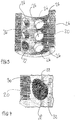
- FIG. 5 a schematic cross section through an inductor 22 according to a further embodiment is shown.
- the inductor 22 has a ferrite body 36, which has an inner cylindrical core 42, which surrounds a continuous hollow cylindrical opening 44 as a central hole, and an outer ring body 48, the inner cylindrical core 42 with the outer ring body 48 by means of a base plate 46 of the ferrite body 36 is connected.
- a fastening means such as a screw or the like, can be introduced into the opening 44 to fasten the inductor 22 in the outer shape.
- annular receptacle 50 of the ferrite body 36 is formed in the outer annular body 48, in which an annular coil 52 with windings is received or arranged.
- the annular receptacle 50 here has a U-shaped shape in cross section.
- the outer ring body 48 and the associated cylindrical core 42 of the inductor 22 are each formed on the side facing the tool shape with a, preferably circular arc-shaped curvature, so that the inductor 22 is complementary in shape to the, preferably curved, outer side of the tool shape, which the inductor 22 is facing, is formed.
- the ferrite body 36 can be made in one piece or in several pieces.
Description
Die Erfindung betrifft eine Heizeinrichtung einer Streckblasmaschine zur Herstellung von Kunststoffhohlkörpern sowie ein Verfahren zum Betreiben einer Streckblasmaschine. Ferner betrifft die Erfindung eine Streckblasmaschine zur Herstellung von Kunststoffhohlkörpern sowie eine Verwendung einer Heizeinrichtung.The invention relates to a heating device of a stretch blow molding machine for the production of plastic hollow bodies and a method for operating a stretch blow molding machine. The invention also relates to a stretch blow molding machine for producing hollow plastic bodies and to the use of a heating device.
Im Stand der Technik sind Blasmaschinen bzw. Streckblasmaschinen zur Blasumformung von Vorformlingen in Behälter bekannt. Hierbei werden bei einer Behälterformung durch Blasdruckeinwirkung Vorformlinge, die aus einem thermoplastischen Material bestehen, durch Expansion mittels Beaufschlagung von Druckluft in einer Form, die auch als Blasform bezeichnet wird, hergestellt.Blow molding machines or stretch blow molding machines for blow molding preforms into containers are known in the prior art. In this case, when a container is formed by the action of blowing pressure, preforms which consist of a thermoplastic material are produced by expansion by applying compressed air in a mold, which is also referred to as a blow mold.
Mit Hilfe der Blasform werden aus den Vorformlingen Behälter oder Kunststoffhohlkörper geblasen, die zur Aufnahme von flüssigen Produkten, wie z.B. Getränken oder anderen Produkten, geeignet sind.With the help of the blow mold, containers or plastic hollow bodies are blown from the preforms, which are suitable for receiving liquid products, such as beverages or other products are.
Beispielsweise ist in
Aus
Aus
Die Aufgabe der Erfindung besteht darin, die Erwärmung von Blasformen zur Herstellung von Kunststoffhohlkörpern zu vereinfachen, wobei eine Heizeinrichtung einer Streckblasmaschine, ein Verfahren zum Betreiben der Streckblasmaschine mit einer solchen Heizeinrichtung, eine Streckblasmaschine mit einer solchen Heizeinrichtung sowie die Verwendung einer Heizeinrichtung angegeben werden soll und diese Heizeinrichtung eine verbesserte Lebensdauer aufweisen soll.The object of the invention is to simplify the heating of blow molds for the production of plastic hollow bodies, whereby a heating device of a stretch blow molding machine, a method for operating the stretch blow molding machine with such a heating device, a stretch blow molding machine with such a heating device and the use of a heating device are to be specified and this heating device should have an improved service life.
Gelöst wird diese Aufgabe durch eine Heizeinrichtung einer Streckblasmaschine zur Herstellung von Kunststoffhohlkörpern mit einer einen Hohlraum aufweisenden Werkzeugform und einer die Werkzeugform umgebenden Außenform für die Werkzeugform, wobei die Außenform wenigstens eine oder mehrere Induktoren aufweist, wobei der wenigstens eine Induktor oder die Induktoren mit einem Induktionsgenerator zur Ansteuerung des oder der Induktoren verbunden ist, dadurch gekennzeichnet, dass der wenigstens eine oder die mehreren Induktoren jeweils eine ringförmige Spule aufweisen, wobei die Spule zwischen einem Kern und einem Ringkörper angeordnet ist, und der Kern und der Ringkörper Magnetfeldausrichtkörper sind, die Ferritmaterial aufweisen und ringförmig oder rohrförmig ausgebildet sind, und wobei der Kern und der Ringkörper über eine scheibenförmig oder plattenförmig ausgebildete Bodenplatte als weiterer Magnetfeldausrichtkörper verbunden sind.This object is achieved by a heating device of a stretch blow molding machine for the production of plastic hollow bodies with a tool mold having a cavity and an outer shape for the tool shape surrounding the tool shape, the outer shape having at least one or more inductors, the at least one inductor or inductors with an induction generator is connected for controlling the inductor or inductors, characterized in that the at least one or more inductors each have an annular coil, the coil being arranged between a core and an annular body, and the core and the annular body are magnetic field alignment bodies which have ferrite material and are ring-shaped or tubular, and wherein the core and the ring body are connected via a disk-shaped or plate-shaped base plate as a further magnetic field alignment body.
Die Erfindung beruht auf dem Gedanken, eine induktive Heizeinrichtung für eine Werkzeugform, die auch als Blasform bezeichnet wird, bereitzustellen, so dass mittels der induktiven Heizeinrichtung es möglich ist, die Werkzeugform direkt auf induktive Weise zu beheizen. Hierbei ist die Werkzeugform von einer Außenform umgeben, so dass durch die Erzeugung eines Wechselmagnetfeldes mittels der Induktoren der Außenform das Wechselmagnetfeld die elektrisch leitfähige Werkzeugform durchdringt und dadurch Wärme in der Werkzeugform erzeugt wird. Durch das elektromagnetische Wechselfeld der Induktoren bei Beaufschlagung der Induktionsspulen der Induktoren mit Wechselspannung werden in der Werkzeugform Wirbelströme induziert und Ummagnetisierung erzeugt, wobei aufgrund von Ummagnetisierungsverlusten und von ohmschen Verlusten durch die Wirbelströme die in die Werkzeugform übertragene Leistung in Wärme umgewandelt wird, wodurch eine Erwärmung der Werkzeugform bewirkt wird.The invention is based on the idea of providing an inductive heating device for a tool mold, which is also referred to as a blow mold, so that by means of the inductive heating device it is possible to heat the tool mold directly in an inductive manner. The tool shape is surrounded by an outer shape, so that by generating an alternating magnetic field by means of the inductors of the outer shape, the alternating magnetic field penetrates the electrically conductive tool shape and heat is generated in the tool shape. Due to the electromagnetic alternating field of the inductors when the induction coils of the inductors are applied with alternating voltage, eddy currents are induced in the tool mold and magnetic reversal is generated, whereby due to magnetic reversal losses and ohmic losses through the eddy currents, the power transferred into the tool mold is converted into heat, which causes the Tool shape is effected.
Im Gegensatz zum Stand der Technik, bei dem die Werkzeugformen mittels der Durchführung von warmen Flüssigkeiten, wie z.B. Wasser oder Öl, durch die Werkzeugform in entsprechenden Kanälen, ist bei der erfindungsgemäßen Heizeinrichtung eine direkte, elektrische Beheizung ermöglicht, wodurch eine Vereinfachung im Aufbau erreicht wird. Darüber hinaus ist es mittels der erfindungsgemäßen Heizeinrichtung möglich, einzelne oder mehrere Segmente der Werkzeugform differenziert bzw. unterschiedlich zu beheizen.In contrast to the prior art, in which the tool molds by means of the passage of warm liquids, e.g. Water or oil, through the shape of the tool in corresponding channels, enables direct electrical heating in the heating device according to the invention, which simplifies the structure. In addition, by means of the heating device according to the invention, it is possible to differentiate or differently heat individual or several segments of the tool shape.
Hierbei weist die Heizeinrichtung, insbesondere Induktionsheizeinrichtung, einen Induktionsgenerator auf, mittels dem der oder die Induktoren angesteuert und mit einer Wechselspannung beaufschlagt werden. Hierbei speist der Induktionsgenerator den oder die Induktoren mit einem Wechselstrom. Die Induktoren sind hierbei außerhalb der zu beheizenden Werkzeugform angeordnet, so dass das magnetische Wechselfeld in Richtung der zu beheizenden Werkzeugform gerichtet ist, wodurch in der metallischen Werkzeugform die Wärme durch die magnetischen Wechselfelder der Induktoren erzeugt wird.Here, the heating device, in particular an induction heating device, has an induction generator, by means of which the inductor or inductors are controlled and an alternating voltage is applied. Here, the induction generator feeds the inductor or inductors with an alternating current. The inductors are arranged outside the tool mold to be heated, so that the alternating magnetic field is directed in the direction of the tool mold to be heated, whereby the heat is generated in the metallic tool mold by the alternating magnetic fields of the inductors.
Dazu ist in einer Ausführungsform der Heizeinrichtung vorgesehen, dass mehrere Induktoren seriell oder parallel geschaltet sind.To this end, one embodiment of the heating device provides that several inductors are connected in series or in parallel.
Darüber hinaus ist gemäß einem weiteren Aspekt der Heizeinrichtung vorteilhafterweise vorgesehen, dass mehrere Gruppen von seriell geschalteten Induktoren parallel geschaltet sind.In addition, according to a further aspect of the heating device, it is advantageously provided that several groups of series-connected inductors are connected in parallel.
Durch die serielle oder parallele Schaltung von Induktoren oder von Gruppen von Induktoren ist es möglich, verschiedene Bereiche oder einzelne Segmente der Werkzeugform selektiv zu erwärmen, wodurch ein vorbestimmter Temperaturgradient innerhalb der Werkzeugform ausgebildet ist.By connecting inductors or groups of inductors in series or in parallel, it is possible to selectively heat different areas or individual segments of the mold, whereby a predetermined temperature gradient is formed within the tool mold.
Hierbei ist es im Rahmen der Erfindung vorgesehen, dass Gruppen von seriell geschalteten Induktoren einzeln angesteuert werden, wodurch einzelne Segmente der Werkzeugform erwärmt werden. Sind Gruppen von seriell geschalteten Induktoren parallel geschaltet, die über einen Generatorausgang angesteuert werden, wird eine vollständige Erwärmung der Werkzeugform erreicht. Im Rahmen der Erfindung ist es in einer Ausgestaltung vorgesehen, dass die Induktoren auch einzeln angesteuert werden.It is provided within the scope of the invention that groups of serially connected inductors are controlled individually, whereby individual segments of the tool mold are heated. If groups of serially connected inductors are connected in parallel, which are controlled via a generator output, the mold mold is completely heated. In the context of the invention it is provided in one embodiment that the inductors are also controlled individually.
Des Weiteren zeichnet sich eine Weiterbildung der Heizeinrichtung dadurch aus, dass die Induktoren in regelmäßigen Abständen zueinander in Aufnahmen der Außenform für die Induktoren angeordnet sind.Furthermore, a further development of the heating device is characterized in that the inductors are arranged at regular intervals from one another in receptacles in the outer shape for the inductors.
Außerdem ist es bei der Heizeinrichtung bevorzugt, dass die Werkzeugform und die Außenform für die Werkzeugform formschlüssig angeordnet sind oder dass die Werkzeugform und die Außenform für die Werkzeugform in einem konstanten Abstand voneinander beabstandet sind, wobei insbesondere der Abstand der Werkzeugform und der Außenform zwischen 0,1 cm bis 1,0 cm, insbesondere 0,1 cm bis 0,5 cm, beträgt. Vorzugsweise ist der Abstand zwischen der Außenform und der Werkzeugform konstant. Insbesondere ist der Abstand zwischen der Außenform und der Werkzeugform konstant.In addition, it is preferred for the heating device that the tool shape and the outer shape for the tool shape are arranged in a form-fitting manner or that the tool shape and the outer shape for the tool shape are spaced apart at a constant distance, in particular the distance between the tool shape and the outer shape being between 0, 1 cm to 1.0 cm, in particular 0.1 cm to 0.5 cm. The distance between the outer shape and the tool shape is preferably constant. In particular, the distance between the outer shape and the tool shape is constant.
Insbesondere ist bei der Heizeinrichtung weiterhin vorgesehen, dass die Werkzeugform aus Stahl, insbesondere Edelstahl, hergestellt ist oder dass die Werkzeugform eine aus Stahl, insbesondere Edelstahl, bestehende Außenhülle aufweist. Dadurch ist es beispielsweise möglich, dass die Werkzeugform eine Außenhülle aus Stahl oder Edelstahl aufweist, die eine Werkzeuginnenform aus Aluminium oder einem anderen Metall umgibt, so dass eine zwei- oder mehrteilige Werkzeugform bereitgestellt wird.In particular, it is also provided in the heating device that the tool shape is made of steel, in particular stainless steel, or that the tool shape is made of steel, in particular Stainless steel, having existing outer shell. This makes it possible, for example, for the tool mold to have an outer casing made of steel or stainless steel, which surrounds an internal tool mold made of aluminum or another metal, so that a two-part or multi-part tool mold is provided.
Überdies ist gemäß einer bevorzugten Ausführungsform bei der Heizeinrichtung vorgesehen, dass die Induktoren mittels des Induktorgenerators einzeln angesteuert werden oder ansteuerbar sind und/oder dass mehrere Induktoren mittels des Induktorgenerators gleichzeitig angesteuert werden oder ansteuerbar sind und/oder dass die Induktoren mittels des Induktorgenerators derart angesteuert werden oder ansteuerbar sind, dass entlang der Längserstreckung und/oder in Umfangsrichtung der Werkzeugform ein vorbestimmter Temperaturgradient ausgebildet wird oder ist.In addition, according to a preferred embodiment, the heating device provides that the inductors are or can be controlled individually by means of the inductor generator and / or that several inductors are controlled or can be controlled simultaneously by means of the inductor generator and / or that the inductors are controlled in this way by means of the inductor generator or can be controlled so that a predetermined temperature gradient is or is formed along the longitudinal extent and / or in the circumferential direction of the tool shape.
Ferner wird die Erfindung gelöst durch ein Verfahren zum Betreiben einer Streckblasmaschine zur Herstellung von Kunststoffhohlkörpern in Werkzeugformen mit einer voranstehend beschriebenen erfindungsgemäßen induktiven Heizeinrichtung. Zur Vermeidung von Wiederholungen wird auf die obige Ausführung ausdrücklich verwiesen.The invention is also achieved by a method for operating a stretch blow molding machine for the production of hollow plastic bodies in tool forms with an inductive heating device according to the invention described above. To avoid repetition, reference is expressly made to the above statement.
Außerdem wird die Aufgabe gelöst durch eine Streckblasmaschine zur Herstellung von Kunststoffhohlkörpern mit einer erfindungsgemäßen Heizeinrichtung.In addition, the object is achieved by a stretch blow molding machine for the production of plastic hollow bodies with a heating device according to the invention.
Eine weitere Lösung erfolgt durch eine Verwendung einer Heizeinrichtung, wie voranstehend beschrieben, in einer Streckblasmaschine zur Herstellung von Kunststoffhohlkörpern.Another solution is to use a heating device, as described above, in a stretch blow molding machine for the production of hollow plastic bodies.
Weitere Merkmale der Erfindung werden aus der Beschreibung erfindungsgemäßer Ausführungsformen zusammen mit den Ansprüchen und den beigefügten Zeichnungen ersichtlich. Erfindungsgemäße Ausführungsformen können einzelne Merkmale oder eine Kombination mehrerer Merkmale erfüllen.Further features of the invention will become apparent from the description of embodiments according to the invention together with the claims and the accompanying drawings. Embodiments according to the invention can fulfill individual features or a combination of several features.
Die Erfindung wird nachstehend ohne Beschränkung des allgemeinen Erfindungsgedankens anhand von Ausführungsbeispielen unter Bezugnahme auf die Zeichnungen beschrieben, wobei bezüglich aller im Text nicht näher erläuterten erfindungsgemäßen Einzelheiten ausdrücklich auf die Zeichnungen verwiesen wird. Es zeigen:
- Fig. 1
- schematisch einen Querschnitt durch eine erfindungsgemäße Blasform für einen Vorformling im Ausschnitt;
- Fig. 2
- schematisch einen Querschnitt durch eine Außenform der Blasform;
- Fig. 3
- schematisch eine weitere perspektivische Darstellung der Außenform;
- Fig. 4
- schematisch eine perspektivische Ansicht eines Induktors in der Außenform in einem Ausschnitt und
- Fig. 5
- schematisch einen Querschnitt durch einen Induktor für die Außenform gemäß einer weiteren Ausführungsform.
- Fig. 1
- schematically, a cross section through a blow mold according to the invention for a preform in the cutout;
- Fig. 2
- schematically a cross section through an outer mold of the blow mold;
- Fig. 3
- schematically another perspective illustration the outer shape;
- Fig. 4
- schematically a perspective view of an inductor in the outer shape in a section and
- Fig. 5
- schematically a cross section through an inductor for the outer shape according to a further embodiment.
In den Zeichnungen sind jeweils gleiche oder gleichartige Elemente und/oder Teile mit denselben Bezugsziffern versehen, so dass von einer erneuten Vorstellung jeweils abgesehen wird.In the drawings, the same or similar elements and / or parts are provided with the same reference numerals, so that they are not introduced again.
In
Hierzu weist die Blasform 10 eine Formhälfte 12 auf, die im Inneren einen Hohlraum 14 zur Aufnahme eines Vorformlings aufweist. In den Hohlraum 14 wird durch eine unterseitige Öffnung 16 der Formhälfte 12 ein Vorformling eingebracht. Vorzugsweise besteht hierbei der (hier nicht dargestellte) Vorformling aus einem thermoplastischen Material, wie zum Beispiel Polyethylenterephthalat (PET). Zum Blasformen des eingesetzten Vorformlings wird Formhälfte 12 zusammen mit einer weiteren (baugleichen) Formhälfte geschlossen.For this purpose, the
Die Formhälfte 12 weist eine zylindrische Außenfläche auf, die von einer Außenform 20 der Blasform umgeben ist. Die Außenform 20 ist hierbei mit einer erfindungsgemäßen induktiven Heizung für die Formhälfte 12 ausgebildet.The
In den
Aus
Um die Induktoren 22 mit Wechselstrom zu beaufschlagen, ist ein Induktionsgenerator 24 vorgesehen (vgl.
Mittels der an der als Werkzeugform ausgebildeten Formhälfte 12 angeordneten Induktoren 22 (vgl.
Die Induktoren 22 können in einer Ausgestaltung seriell oder parallel geschaltet sein, wobei die Induktoren 22 hierbei mit dem Induktionsgenerator 24 verbunden sind. In einer Ausgestaltung können hierbei Gruppen von seriell geschalteten Induktoren 22 jeweils zu einer anderen Gruppe von seriell angeordneten Induktoren 22 parallel geschaltet sein, wodurch es möglich ist, infolge der Ansteuerung durch den Induktionsgenerator 24 einzelne Segmente in der Formhälfte 12 gezielt zu erwärmen.In one embodiment, the
In
Die Induktionsspule 30 ist ferner von einem Ringkörper 32 umgeben, wobei der Ringkörper 32 und der Kern 28 Ferritmaterial oder Ferrite aufweisen, wodurch der Kern 28 und der Ringkörper 32 als Magnetfeldausrichtkörper ausgerichtet sind, so dass das von der Induktionsspule 30 erzeugte magnetische Wechselfeld in Richtung der von der Außenform 20 ummantelten Formhälfte 12 gerichtet ist.The
In
Mittels des inneren zylindrischen Kerns 42, der Bodenplatte 46 und dem äußeren Ringkörper 48 wird eine ringförmige Aufnahme 50 des Ferritkörpers 36 ausgebildet, in der eine ringförmige Spule 52 mit Wicklungen aufgenommen bzw. angeordnet ist. Die ringförmige Aufnahme 50 weist hierbei im Querschnitt eine U-förmige Form auf.By means of the inner
Der äußere Ringkörper 48 und der damit verbundene zylindrische Kern 42 des Induktors 22 sind auf der der Werkzeugform zugewandten Seite jeweils mit einer, vorzugsweise kreisbogenförmigen, Krümmung ausgebildet, so dass der Induktor 22 formkomplementär zur, vorzugsweise gekrümmten, Außenseite der Werkzeugform, die dem Induktor 22 zugewandt ist, ausgebildet ist.The
In Ausgestaltungen des Induktors 22 kann der Ferritkörper 36 einteilig oder mehrteilig ausgeführt sein.In configurations of the
Im Rahmen der Erfindung sind Merkmale, die mit "insbesondere" oder "vorzugsweise" gekennzeichnet sind, als fakultative Merkmale zu verstehen.In the context of the invention, features that are identified with “in particular” or “preferably” are to be understood as optional features.
- 1010
- BlasformBlow mold
- 1212th
- FormhälfteMold half
- 1414th
- Hohlraumcavity
- 1616
- Öffnungopening
- 2020th
- AußenformOuter shape
- 2222nd
- InduktorInductor
- 2424
- InduktionsgeneratorInduction generator
- 2626th
- Aufnahmeadmission
- 2828
- Kerncore
- 3030th
- InduktionsspuleInduction coil
- 3232
- RingkörperRing body
- 3636
- FerritkörperFerrite body
- 4242
- innerer zylindrischer Kerninner cylindrical core
- 4444
- DurchbrechungBreakthrough
- 4646
- BodenplatteBase plate
- 4848
- äußerer Ringkörperouter ring body
- 5050
- Aufnahmeadmission
- 5252
- ringförmige Spuleannular coil
- SS.
- StreckblasmaschineStretch blow molding machine
Claims (10)
- A heating device of a stretch blowing machine and for producing hollow plastic bodies with a tool mold (12) having a cavity (14) and an outer mold (20) surrounding the tool mold (12) for the tool mold (12), wherein the outer mold (20) has at least one or more inductors, wherein the at least one inductor (22) or the inductors (22) is/are connected to an induction generator (24) in order to actuate the inductor(s) (22), characterized in that the at least one or the multiple inductors (22) each have an annular coil (30), wherein the coil (30) is arranged between a core (28) and an annular body (32), and the core (28) and the annular body (32) are magnetic field orienting bodies (28, 32) which have ferritic material and have an annular or tubular configuration, and wherein the core (28) and the annular body (32) are connected via a base plate (46) having a disk-shaped or plate-shaped configuration as a further magnetic field orienting body.
- The heating device according to Claim 1, characterized in that multiple inductors (22) are connected in series or in parallel.
- The heating device according to Claim 1, characterized in that multiple groups of series-connected inductors (22) are connected in parallel.
- The heating device according to any one of Claims 1 to 3, characterized in that the inductors (22) are arranged at regular distances from one another in receptacles (26) of the outer mold (20) for the inductors (22).
- The heating device according to any one of Claims 1 to 4, characterized in that the tool mold (12) and the outer mold (20) for the tool mold (12) are arranged with a positive fit or the tool mold (12) and the outer mold (20) for the tool mold (12) are spaced apart from one another at a constant distance, wherein in particular the distance of the tool mold (12) and the outer mold (20) is between 0.1 cm and 1.0 cm, in particular is 0.1 cm to 0.5 cm.
- The heating device according to any one of Claims 1 to 5, characterized in that the tool mold (12) is produced from steel, in particular stainless steel, or the tool mold (12) has an outer shell consisting of steel, in particular stainless steel.
- The heating device according to any one of Claims 1 to 6, characterized in that the inductors (22) are or can be individually actuated by means of the inductor generator and/or multiple inductors (22) are or can be simultaneously actuated by means of the inductor generator and/or the inductors (22) are or can be actuated by means of the inductor generator such that a predetermined temperature gradient is or will be configured along the longitudinal extension and/or in the circumferential direction of the tool mold (12).
- A stretch blowing machine for producing hollow plastic bodies having a heating device according to any one of Claims 1 to 7.
- A method for operating a stretch blowing machine having a heating device according to any one of Claims 1 to 7.
- Use of a heating device according to any one of Claims 1 to 7 in a stretch blowing machine for producing hollow plastic bodies.
Priority Applications (1)
| Application Number | Priority Date | Filing Date | Title |
|---|---|---|---|
| EP18169449.8A EP3560671B1 (en) | 2018-04-26 | 2018-04-26 | Heating device of a stretch blowing machine |
Applications Claiming Priority (1)
| Application Number | Priority Date | Filing Date | Title |
|---|---|---|---|
| EP18169449.8A EP3560671B1 (en) | 2018-04-26 | 2018-04-26 | Heating device of a stretch blowing machine |
Publications (3)
| Publication Number | Publication Date |
|---|---|
| EP3560671A1 EP3560671A1 (en) | 2019-10-30 |
| EP3560671A8 EP3560671A8 (en) | 2019-12-25 |
| EP3560671B1 true EP3560671B1 (en) | 2020-12-30 |
Family
ID=62067458
Family Applications (1)
| Application Number | Title | Priority Date | Filing Date |
|---|---|---|---|
| EP18169449.8A Active EP3560671B1 (en) | 2018-04-26 | 2018-04-26 | Heating device of a stretch blowing machine |
Country Status (1)
| Country | Link |
|---|---|
| EP (1) | EP3560671B1 (en) |
Family Cites Families (7)
| Publication number | Priority date | Publication date | Assignee | Title |
|---|---|---|---|---|
| DE19802855A1 (en) * | 1998-01-26 | 1998-07-09 | Protoned Bv | Hollow or flat composite plastic product manufacture and moulding tool |
| FR2816237B1 (en) * | 2000-11-08 | 2003-09-19 | Roctool | MOLDS FOR PROCESSING PLASTICS AND COMPOSITES AND ASSOCIATED PROCESSING METHOD |
| FR2867939B1 (en) * | 2004-03-18 | 2007-08-10 | Roctool | METHOD FOR HEATING MATERIALS TO PRODUCE OBJECTS AND DEVICE USING THE METHOD |
| JP5513079B2 (en) * | 2009-11-06 | 2014-06-04 | 三菱レイヨン株式会社 | Mold and method for producing thermoplastic resin fiber reinforced composite material molded article |
| US9820339B2 (en) * | 2011-09-29 | 2017-11-14 | The Boeing Company | Induction heating using induction coils in series-parallel circuits |
| FR3051136A1 (en) * | 2016-05-10 | 2017-11-17 | Roctool | METHOD AND DEVICE FOR HEATING A MOLD |
| DE102016113875B4 (en) | 2016-07-27 | 2019-07-18 | Khs Corpoplast Gmbh | Heating device for a blowing machine with conveyor chain for a double-row transport of the preforms |
-
2018
- 2018-04-26 EP EP18169449.8A patent/EP3560671B1/en active Active
Non-Patent Citations (1)
| Title |
|---|
| None * |
Also Published As
| Publication number | Publication date |
|---|---|
| EP3560671A1 (en) | 2019-10-30 |
| EP3560671A8 (en) | 2019-12-25 |
Similar Documents
| Publication | Publication Date | Title |
|---|---|---|
| DE4407065B4 (en) | Valve-controlled injection molding nozzle with valve needle guiding device | |
| DE2522884A1 (en) | METHOD AND DEVICE FOR MANUFACTURING ORIENTED HOLLOW BODIES FROM PLASTIC | |
| EP2208597B1 (en) | Resonator unit, expansion method and device for heating containers | |
| EP3073615A1 (en) | Self-adhesive groove closure device for an electric machine | |
| EP1584452B1 (en) | Process for forming a formstable hollowlike element having a bottom and use of such an element. | |
| EP3560671B1 (en) | Heating device of a stretch blowing machine | |
| DE102011053867B4 (en) | Injection mold with inductor for the production of plastic moldings | |
| DE102011108157A1 (en) | Molding tool for production of fiber-reinforced plastic components, has electrically insulating molding surfaces, which are designed for limiting molding cavity, where one or both tool sections are made from electrically insulating material | |
| DE102015221168A1 (en) | Method and manufacturing device for producing a double toothed belt | |
| WO2017055260A1 (en) | Screw machine and corresponding method for preparing plastic material | |
| WO2015154973A1 (en) | Screw machine and method for preparing a plastic material | |
| EP3684579B1 (en) | Method for producing spacers for a winding unit | |
| EP3134248B1 (en) | Device and method for cycle- and cost-optimized thermal transformation of hose blanks | |
| DE102019002234A1 (en) | Impregnation device for trickle impregnation of a strator of an electric machine | |
| EP1065037B1 (en) | Process of and apparatus for heating of injection moulds | |
| DE698534C (en) | ||
| DE102012003174A1 (en) | Method for manufacturing hollow profile with sections of different wall thickness, involves moving holding positions in succession, so that compressing section of hollow profiles is compressed into compression limiting space | |
| DE2143073A1 (en) | Device for smoothing the inner surface of a plastic tube | |
| EP3810398B1 (en) | Device for producing containers by blow moulding | |
| DE102013012971A1 (en) | Heating station, useful in pressing line of pressing tool for heating metal sheet, comprises lower tool and upper tool that are displaced relative to each other into open position and closed position, and receptacle for holding metal sheet | |
| DE102015109289B3 (en) | Method and device for introducing openings in semi-finished fiber products | |
| DE202018106268U1 (en) | Tool for producing molds or cores by electrical resistance heating of a plastic-based material | |
| DE102013010304A1 (en) | Method for producing a fiber-reinforced plastic component | |
| DE102011075107A1 (en) | Apparatus for controlling temperature of tool for producing or processing workpiece, has heating element which is formed in shape of pin that is adjustable to area of tool kept at moderate temperature | |
| DE1158698B (en) | Method and device for producing squeeze tubes from thermoplastic material |
Legal Events
| Date | Code | Title | Description |
|---|---|---|---|
| PUAI | Public reference made under article 153(3) epc to a published international application that has entered the european phase |
Free format text: ORIGINAL CODE: 0009012 |
|
| STAA | Information on the status of an ep patent application or granted ep patent |
Free format text: STATUS: THE APPLICATION HAS BEEN PUBLISHED |
|
| AK | Designated contracting states |
Kind code of ref document: A1 Designated state(s): AL AT BE BG CH CY CZ DE DK EE ES FI FR GB GR HR HU IE IS IT LI LT LU LV MC MK MT NL NO PL PT RO RS SE SI SK SM TR |
|
| AX | Request for extension of the european patent |
Extension state: BA ME |
|
| RAP1 | Party data changed (applicant data changed or rights of an application transferred) |
Owner name: KENDRION KUHNKE AUTOMATION GMBH |
|
| STAA | Information on the status of an ep patent application or granted ep patent |
Free format text: STATUS: REQUEST FOR EXAMINATION WAS MADE |
|
| 17P | Request for examination filed |
Effective date: 20200424 |
|
| RBV | Designated contracting states (corrected) |
Designated state(s): AL AT BE BG CH CY CZ DE DK EE ES FI FR GB GR HR HU IE IS IT LI LT LU LV MC MK MT NL NO PL PT RO RS SE SI SK SM TR |
|
| GRAP | Despatch of communication of intention to grant a patent |
Free format text: ORIGINAL CODE: EPIDOSNIGR1 |
|
| STAA | Information on the status of an ep patent application or granted ep patent |
Free format text: STATUS: GRANT OF PATENT IS INTENDED |
|
| RIC1 | Information provided on ipc code assigned before grant |
Ipc: B29C 49/48 20060101ALI20200930BHEP Ipc: B29C 49/06 20060101ALN20200930BHEP Ipc: B29K 67/00 20060101ALN20200930BHEP Ipc: B29C 35/08 20060101AFI20200930BHEP |
|
| RIC1 | Information provided on ipc code assigned before grant |
Ipc: B29C 49/06 20060101ALN20201014BHEP Ipc: B29C 49/48 20060101ALI20201014BHEP Ipc: B29K 67/00 20060101ALN20201014BHEP Ipc: B29C 35/08 20060101AFI20201014BHEP |
|
| GRAS | Grant fee paid |
Free format text: ORIGINAL CODE: EPIDOSNIGR3 |
|
| INTG | Intention to grant announced |
Effective date: 20201030 |
|
| GRAA | (expected) grant |
Free format text: ORIGINAL CODE: 0009210 |
|
| STAA | Information on the status of an ep patent application or granted ep patent |
Free format text: STATUS: THE PATENT HAS BEEN GRANTED |
|
| AK | Designated contracting states |
Kind code of ref document: B1 Designated state(s): AL AT BE BG CH CY CZ DE DK EE ES FI FR GB GR HR HU IE IS IT LI LT LU LV MC MK MT NL NO PL PT RO RS SE SI SK SM TR |
|
| REG | Reference to a national code |
Ref country code: GB Ref legal event code: FG4D Free format text: NOT ENGLISH |
|
| REG | Reference to a national code |
Ref country code: AT Ref legal event code: REF Ref document number: 1349477 Country of ref document: AT Kind code of ref document: T Effective date: 20210115 |
|
| REG | Reference to a national code |
Ref country code: DE Ref legal event code: R096 Ref document number: 502018003430 Country of ref document: DE |
|
| REG | Reference to a national code |
Ref country code: IE Ref legal event code: FG4D Free format text: LANGUAGE OF EP DOCUMENT: GERMAN |
|
| PG25 | Lapsed in a contracting state [announced via postgrant information from national office to epo] |
Ref country code: RS Free format text: LAPSE BECAUSE OF FAILURE TO SUBMIT A TRANSLATION OF THE DESCRIPTION OR TO PAY THE FEE WITHIN THE PRESCRIBED TIME-LIMIT Effective date: 20201230 Ref country code: FI Free format text: LAPSE BECAUSE OF FAILURE TO SUBMIT A TRANSLATION OF THE DESCRIPTION OR TO PAY THE FEE WITHIN THE PRESCRIBED TIME-LIMIT Effective date: 20201230 Ref country code: GR Free format text: LAPSE BECAUSE OF FAILURE TO SUBMIT A TRANSLATION OF THE DESCRIPTION OR TO PAY THE FEE WITHIN THE PRESCRIBED TIME-LIMIT Effective date: 20210331 Ref country code: NO Free format text: LAPSE BECAUSE OF FAILURE TO SUBMIT A TRANSLATION OF THE DESCRIPTION OR TO PAY THE FEE WITHIN THE PRESCRIBED TIME-LIMIT Effective date: 20210330 |
|
| PG25 | Lapsed in a contracting state [announced via postgrant information from national office to epo] |
Ref country code: BG Free format text: LAPSE BECAUSE OF FAILURE TO SUBMIT A TRANSLATION OF THE DESCRIPTION OR TO PAY THE FEE WITHIN THE PRESCRIBED TIME-LIMIT Effective date: 20210330 Ref country code: SE Free format text: LAPSE BECAUSE OF FAILURE TO SUBMIT A TRANSLATION OF THE DESCRIPTION OR TO PAY THE FEE WITHIN THE PRESCRIBED TIME-LIMIT Effective date: 20201230 Ref country code: LV Free format text: LAPSE BECAUSE OF FAILURE TO SUBMIT A TRANSLATION OF THE DESCRIPTION OR TO PAY THE FEE WITHIN THE PRESCRIBED TIME-LIMIT Effective date: 20201230 |
|
| REG | Reference to a national code |
Ref country code: NL Ref legal event code: MP Effective date: 20201230 |
|
| PG25 | Lapsed in a contracting state [announced via postgrant information from national office to epo] |
Ref country code: HR Free format text: LAPSE BECAUSE OF FAILURE TO SUBMIT A TRANSLATION OF THE DESCRIPTION OR TO PAY THE FEE WITHIN THE PRESCRIBED TIME-LIMIT Effective date: 20201230 |
|
| REG | Reference to a national code |
Ref country code: LT Ref legal event code: MG9D |
|
| PG25 | Lapsed in a contracting state [announced via postgrant information from national office to epo] |
Ref country code: LT Free format text: LAPSE BECAUSE OF FAILURE TO SUBMIT A TRANSLATION OF THE DESCRIPTION OR TO PAY THE FEE WITHIN THE PRESCRIBED TIME-LIMIT Effective date: 20201230 Ref country code: PT Free format text: LAPSE BECAUSE OF FAILURE TO SUBMIT A TRANSLATION OF THE DESCRIPTION OR TO PAY THE FEE WITHIN THE PRESCRIBED TIME-LIMIT Effective date: 20210430 Ref country code: RO Free format text: LAPSE BECAUSE OF FAILURE TO SUBMIT A TRANSLATION OF THE DESCRIPTION OR TO PAY THE FEE WITHIN THE PRESCRIBED TIME-LIMIT Effective date: 20201230 Ref country code: SK Free format text: LAPSE BECAUSE OF FAILURE TO SUBMIT A TRANSLATION OF THE DESCRIPTION OR TO PAY THE FEE WITHIN THE PRESCRIBED TIME-LIMIT Effective date: 20201230 Ref country code: EE Free format text: LAPSE BECAUSE OF FAILURE TO SUBMIT A TRANSLATION OF THE DESCRIPTION OR TO PAY THE FEE WITHIN THE PRESCRIBED TIME-LIMIT Effective date: 20201230 Ref country code: CZ Free format text: LAPSE BECAUSE OF FAILURE TO SUBMIT A TRANSLATION OF THE DESCRIPTION OR TO PAY THE FEE WITHIN THE PRESCRIBED TIME-LIMIT Effective date: 20201230 |
|
| PG25 | Lapsed in a contracting state [announced via postgrant information from national office to epo] |
Ref country code: PL Free format text: LAPSE BECAUSE OF FAILURE TO SUBMIT A TRANSLATION OF THE DESCRIPTION OR TO PAY THE FEE WITHIN THE PRESCRIBED TIME-LIMIT Effective date: 20201230 |
|
| PG25 | Lapsed in a contracting state [announced via postgrant information from national office to epo] |
Ref country code: IS Free format text: LAPSE BECAUSE OF FAILURE TO SUBMIT A TRANSLATION OF THE DESCRIPTION OR TO PAY THE FEE WITHIN THE PRESCRIBED TIME-LIMIT Effective date: 20210430 |
|
| REG | Reference to a national code |
Ref country code: DE Ref legal event code: R097 Ref document number: 502018003430 Country of ref document: DE |
|
| PG25 | Lapsed in a contracting state [announced via postgrant information from national office to epo] |
Ref country code: AL Free format text: LAPSE BECAUSE OF FAILURE TO SUBMIT A TRANSLATION OF THE DESCRIPTION OR TO PAY THE FEE WITHIN THE PRESCRIBED TIME-LIMIT Effective date: 20201230 Ref country code: IT Free format text: LAPSE BECAUSE OF FAILURE TO SUBMIT A TRANSLATION OF THE DESCRIPTION OR TO PAY THE FEE WITHIN THE PRESCRIBED TIME-LIMIT Effective date: 20201230 |
|
| PLBE | No opposition filed within time limit |
Free format text: ORIGINAL CODE: 0009261 |
|
| STAA | Information on the status of an ep patent application or granted ep patent |
Free format text: STATUS: NO OPPOSITION FILED WITHIN TIME LIMIT |
|
| PG25 | Lapsed in a contracting state [announced via postgrant information from national office to epo] |
Ref country code: DK Free format text: LAPSE BECAUSE OF FAILURE TO SUBMIT A TRANSLATION OF THE DESCRIPTION OR TO PAY THE FEE WITHIN THE PRESCRIBED TIME-LIMIT Effective date: 20201230 Ref country code: MC Free format text: LAPSE BECAUSE OF FAILURE TO SUBMIT A TRANSLATION OF THE DESCRIPTION OR TO PAY THE FEE WITHIN THE PRESCRIBED TIME-LIMIT Effective date: 20201230 |
|
| 26N | No opposition filed |
Effective date: 20211001 |
|
| PG25 | Lapsed in a contracting state [announced via postgrant information from national office to epo] |
Ref country code: LU Free format text: LAPSE BECAUSE OF NON-PAYMENT OF DUE FEES Effective date: 20210426 |
|
| REG | Reference to a national code |
Ref country code: BE Ref legal event code: MM Effective date: 20210430 |
|
| PG25 | Lapsed in a contracting state [announced via postgrant information from national office to epo] |
Ref country code: LI Free format text: LAPSE BECAUSE OF NON-PAYMENT OF DUE FEES Effective date: 20210430 Ref country code: CH Free format text: LAPSE BECAUSE OF NON-PAYMENT OF DUE FEES Effective date: 20210430 Ref country code: ES Free format text: LAPSE BECAUSE OF FAILURE TO SUBMIT A TRANSLATION OF THE DESCRIPTION OR TO PAY THE FEE WITHIN THE PRESCRIBED TIME-LIMIT Effective date: 20201230 |
|
| PG25 | Lapsed in a contracting state [announced via postgrant information from national office to epo] |
Ref country code: SI Free format text: LAPSE BECAUSE OF FAILURE TO SUBMIT A TRANSLATION OF THE DESCRIPTION OR TO PAY THE FEE WITHIN THE PRESCRIBED TIME-LIMIT Effective date: 20201230 |
|
| PG25 | Lapsed in a contracting state [announced via postgrant information from national office to epo] |
Ref country code: IE Free format text: LAPSE BECAUSE OF NON-PAYMENT OF DUE FEES Effective date: 20210426 |
|
| PG25 | Lapsed in a contracting state [announced via postgrant information from national office to epo] |
Ref country code: IS Free format text: LAPSE BECAUSE OF FAILURE TO SUBMIT A TRANSLATION OF THE DESCRIPTION OR TO PAY THE FEE WITHIN THE PRESCRIBED TIME-LIMIT Effective date: 20210430 |
|
| PG25 | Lapsed in a contracting state [announced via postgrant information from national office to epo] |
Ref country code: BE Free format text: LAPSE BECAUSE OF NON-PAYMENT OF DUE FEES Effective date: 20210430 |
|
| GBPC | Gb: european patent ceased through non-payment of renewal fee |
Effective date: 20220426 |
|
| PG25 | Lapsed in a contracting state [announced via postgrant information from national office to epo] |
Ref country code: GB Free format text: LAPSE BECAUSE OF NON-PAYMENT OF DUE FEES Effective date: 20220426 |
|
| P01 | Opt-out of the competence of the unified patent court (upc) registered |
Effective date: 20230512 |
|
| PG25 | Lapsed in a contracting state [announced via postgrant information from national office to epo] |
Ref country code: NL Free format text: LAPSE BECAUSE OF NON-PAYMENT OF DUE FEES Effective date: 20201230 Ref country code: CY Free format text: LAPSE BECAUSE OF FAILURE TO SUBMIT A TRANSLATION OF THE DESCRIPTION OR TO PAY THE FEE WITHIN THE PRESCRIBED TIME-LIMIT Effective date: 20201230 |
|
| PG25 | Lapsed in a contracting state [announced via postgrant information from national office to epo] |
Ref country code: SM Free format text: LAPSE BECAUSE OF FAILURE TO SUBMIT A TRANSLATION OF THE DESCRIPTION OR TO PAY THE FEE WITHIN THE PRESCRIBED TIME-LIMIT Effective date: 20201230 Ref country code: HU Free format text: LAPSE BECAUSE OF FAILURE TO SUBMIT A TRANSLATION OF THE DESCRIPTION OR TO PAY THE FEE WITHIN THE PRESCRIBED TIME-LIMIT; INVALID AB INITIO Effective date: 20180426 |
|
| PGFP | Annual fee paid to national office [announced via postgrant information from national office to epo] |
Ref country code: FR Payment date: 20230417 Year of fee payment: 6 Ref country code: DE Payment date: 20230418 Year of fee payment: 6 |