EP3559923B1 - Controlling at least one controllable device arranged in a region predefined by a lighting device - Google Patents
Controlling at least one controllable device arranged in a region predefined by a lighting device Download PDFInfo
- Publication number
- EP3559923B1 EP3559923B1 EP17822688.2A EP17822688A EP3559923B1 EP 3559923 B1 EP3559923 B1 EP 3559923B1 EP 17822688 A EP17822688 A EP 17822688A EP 3559923 B1 EP3559923 B1 EP 3559923B1
- Authority
- EP
- European Patent Office
- Prior art keywords
- communication terminal
- controllable
- transmitting device
- beacon
- data
- Prior art date
- Legal status (The legal status is an assumption and is not a legal conclusion. Google has not performed a legal analysis and makes no representation as to the accuracy of the status listed.)
- Active
Links
Images


Classifications
-
- G—PHYSICS
- G08—SIGNALLING
- G08C—TRANSMISSION SYSTEMS FOR MEASURED VALUES, CONTROL OR SIMILAR SIGNALS
- G08C17/00—Arrangements for transmitting signals characterised by the use of a wireless electrical link
- G08C17/02—Arrangements for transmitting signals characterised by the use of a wireless electrical link using a radio link
-
- H—ELECTRICITY
- H04—ELECTRIC COMMUNICATION TECHNIQUE
- H04W—WIRELESS COMMUNICATION NETWORKS
- H04W8/00—Network data management
- H04W8/005—Discovery of network devices, e.g. terminals
-
- H—ELECTRICITY
- H05—ELECTRIC TECHNIQUES NOT OTHERWISE PROVIDED FOR
- H05B—ELECTRIC HEATING; ELECTRIC LIGHT SOURCES NOT OTHERWISE PROVIDED FOR; CIRCUIT ARRANGEMENTS FOR ELECTRIC LIGHT SOURCES, IN GENERAL
- H05B47/00—Circuit arrangements for operating light sources in general, i.e. where the type of light source is not relevant
- H05B47/10—Controlling the light source
- H05B47/175—Controlling the light source by remote control
- H05B47/19—Controlling the light source by remote control via wireless transmission
-
- H—ELECTRICITY
- H05—ELECTRIC TECHNIQUES NOT OTHERWISE PROVIDED FOR
- H05B—ELECTRIC HEATING; ELECTRIC LIGHT SOURCES NOT OTHERWISE PROVIDED FOR; CIRCUIT ARRANGEMENTS FOR ELECTRIC LIGHT SOURCES, IN GENERAL
- H05B47/00—Circuit arrangements for operating light sources in general, i.e. where the type of light source is not relevant
- H05B47/10—Controlling the light source
- H05B47/175—Controlling the light source by remote control
- H05B47/196—Controlling the light source by remote control characterised by user interface arrangements
- H05B47/1965—Controlling the light source by remote control characterised by user interface arrangements using handheld communication devices
-
- H—ELECTRICITY
- H05—ELECTRIC TECHNIQUES NOT OTHERWISE PROVIDED FOR
- H05B—ELECTRIC HEATING; ELECTRIC LIGHT SOURCES NOT OTHERWISE PROVIDED FOR; CIRCUIT ARRANGEMENTS FOR ELECTRIC LIGHT SOURCES, IN GENERAL
- H05B47/00—Circuit arrangements for operating light sources in general, i.e. where the type of light source is not relevant
- H05B47/10—Controlling the light source
- H05B47/175—Controlling the light source by remote control
- H05B47/198—Grouping of control procedures or address assignation to light sources
- H05B47/199—Commissioning of light sources
-
- G—PHYSICS
- G08—SIGNALLING
- G08C—TRANSMISSION SYSTEMS FOR MEASURED VALUES, CONTROL OR SIMILAR SIGNALS
- G08C2201/00—Transmission systems of control signals via wireless link
- G08C2201/90—Additional features
- G08C2201/91—Remote control based on location and proximity
Definitions
- the invention relates to a method for controlling at least one controllable device arranged in a predetermined area by means of a communication terminal, wherein a transmitting device wirelessly transmits a radio signal with identification data specific to the transmitting device.
- the invention relates to a system for controlling at least one controllable device arranged in a predetermined area.
- Lighting devices are used to illuminate rooms, for example outside or inside buildings, in a predetermined manner in order to enable or support intended use.
- lighting devices are increasingly being used which, in addition to a lighting device that emits light in a predeterminable manner, also have a transmitting device which is at least designed to transmit the specific identification data wirelessly, for example in the manner of broadcasting.
- This transmitting device is preferably designed to transmit the radio signal in the manner of local radio.
- a radio standard such as Bluetooth, WiFi, ZigBee or the like can be used to send the radio signal.
- Such a transmitting device is also referred to as a “beacon” in the prior art.
- beacons can be combined with lighting devices in order to provide luminaire-specific or other information using their signal.
- Beacon technology is based on a transmitter system or a transmitter-receiver system.
- a beacon is a small, usually battery-operated transmitter that sends out a signal at, preferably definable, time intervals, for example based on a Bluetooth Low Energy standard (BLE).
- BLE Bluetooth Low Energy standard
- the signal of a beacon is characterized by the specific identification data, which includes, for example, a unique identification number, for example called a universally unic identifier (UUID).
- Beacons can be used to assign identification, in particular digital identification, to objects and/or locations.
- Objects where a beacon is installed, as well as places where a beacon is installed, for example on a wall or a ceiling, can in this way be used by communication devices, for example smartphones, laptops and/or the like, in the signal field of the beacon be identified.
- a location can be identified or location can be carried out.
- a type of radio-based grid can be provided that allows a communication terminal located in the area to use its radio interface, in particular BLE interface, as well as corresponding evaluation options to determine your own position.
- the specific identification data of the installed beacons give a location an identifier, which the communication terminal can use to determine the position, at least approximately.
- a transmission range of a respective beacon can be determined.
- the communication terminal can preferably access data from a data storage, for example via a communication network such as the Internet and/or the like.
- the data storage can be, for example, a cloud server or the like.
- the identification data and an assigned position can be noted on a map.
- the data memory can also be present at least partially on the communication terminal.
- the communication terminal can use the specific identification data determined to determine its own location, for example via a server query.
- the accuracy can be improved using positioning algorithms; in particular, a distance can be determined from a received field strength of the respective signal of the transmitting device or beacon.
- transmitting devices or beacons can be installed in lighting devices of the generic type.
- the advantage can be used that a light installation can provide permanent energy access in order to supply the transmitting device or the beacon with electrical energy.
- the transmitting device or the beacon does not require its own energy supply in the form of a battery and the corresponding maintenance effort can therefore be saved.
- this configuration allows settings of the transmitting device or the beacon to be selected that result in high energy consumption without this necessarily having an impact on the lifespan of the beacon.
- installation processes of such transmitting devices or beacons and lighting technology can be standardized.
- Another advantage is a defined locking position of the transmitting device or the beacon, which is preferably selected such that the transmitting device or the beacon is protected from manipulation. This means that a location can be assigned a reliably secure identifier.
- a beacon can be integrated into a lighting device of a system as a transmitting device.
- the system can include a plurality of lighting devices.
- the lighting device includes one or more lighting devices that provide the desired lighting function.
- the beacon and the lighting device are in place preferably in communication connection with each other.
- the beacon is preferably arranged integrated into the lighting device. There is therefore no need to provide a separate housing for the beacon. This allows the beacon to be arranged in a protected manner at the same time, so that the intended function can be provided with high reliability. Further lighting devices of the system are preferably designed identically to the lighting device.
- the beacon is designed to wirelessly emit a signal, namely the radio signal, with identification data specific to the beacon.
- the transmission is preferably carried out via radio using a BLE standard.
- the beacon preferably further comprises a control unit which comprises a computer unit and a storage unit. An executable computer program is stored in the storage unit and is available for the computer unit, so that a predetermined control function can be achieved using the computer unit.
- the beacon can also be connected to other local beacons via a communication connection.
- the communication connection is preferably also designed as a wireless communication connection, in particular according to the BLE standard. But it can also be at least partially wired.
- the communication connection between the beacon and the other beacons is, for example, bidirectional. But it can also be at least partially unidirectional.
- the beacon can be connected to a data infrastructure device via another communication connection.
- the data infrastructure device can serve to control the system, here in particular the lighting devices of the system.
- the infrastructure facility can do this, for example Internet or a central service server.
- the data infrastructure device can also be used to control and/or transmit data.
- the local beacon of the lighting device can be designed as a pure transmitting device in the manner of a broadcasting operation or as a combined transmitting-receiving device.
- the beacon signal can be received using communication terminals such as a smartphone, a LAPTOP and/or the like.
- users or devices may have the challenge of having to orient themselves within an area, navigate or want to find or use other local digital services, such as apps, app functions, Google Maps, Lightify, lighting control and/ or similar.
- the system with integrated beacons in a specified area can become a location or orientation system for these potential uses.
- services can now be provided, for example navigation, provision of location-specific information and/or the like.
- beacon technology is the ability to configure typical parameters, such as a signal strength, a transmission interval and/or the like, of the beacon.
- typical parameters such as a signal strength, a transmission interval and/or the like.
- Different application scenarios can be individually supported with different configurations. If, for example, a high quality of service is desired with regard to precise localization at short intervals, for example in indoor navigation, very short transmission intervals can be configured, for example.
- DALI Digital Addressable Lighting Interfaces
- the lighting devices need a unique address that reflects their position in a specified area.
- the expert calls such an assignment of lighting devices to corresponding positions or addresses “picking”.
- several pieces of information must be brought together, namely the unique identification data of a respective lighting device, an installation location of the respective lighting device in a predetermined area, that is, a physical address of the lighting device, and an identifier of the lighting device, that is, for example its digital address.
- the digital address of a lighting device can usually be transmitted to a controller or data processor via powerline communication or a similar power-based communication connection via the energy distribution.
- the lighting device or a ballast of the lighting device can thus register with the control with its digital address.
- this does not yet provide information about the physical location at which the lighting device is actually located in the specified area.
- this information is necessary if only a defined area is to be illuminated, for example only a meeting room or a part of it or the like.
- lighting devices or lamps and their location cannot generally be easily identified electronically. Typically, it can only be recognized via a sticker or an imprint, for example on a housing the lighting device, what type of lighting device or light source it is.
- Another complex option is to have each digitally registered lighting device flash individually within the system and to manually mark position information in a layout.
- LMS light management system
- positions of the lighting devices or lamps for a lighting area are usually defined in an installation plan, for example as a predetermined area or service area. This specifies to an installer which of the delivered or commissioned lighting devices, for example with regard to a type of lamp or the like, should be arranged at which position in the area, for example the building, according to the installation plan.
- Location-based services or services such as navigation of a user or the like, using beacons should be available to the user in a specified area, preferably permanently and without restrictions.
- this also requires regular maintenance or, if necessary, updating of computer programs such as firmware or the like.
- Firmware updates of technical systems are particularly important. They usually serve to eliminate errors, optimize performance and, if necessary, expand the functionality of the technical system. For example, errors can So-called bugs can be fixed, which can increase reliability.
- security gaps can be closed or technical functions of the system can be subsequently activated or deactivated. This explains the high need to carry out firmware updates at regular, particularly situation-specific, intervals.
- Controllable technical infrastructure elements or devices are often also arranged in a predetermined area, in which at least one beacon is often arranged, for example the lighting device, an air conditioning system, blinds and/or the like.
- these controllable devices can increasingly be controlled using communication terminals such as smartphones, tablets and/or the like. The control takes place depending on the respective controllable device via a wide variety of communication interfaces, such as WLAN, Bluetooth, ZigBee, DALI bus and/or the like.
- the invention is therefore based on the object of improving a method for controlling a controllable device and a system for this.
- the invention proposes a method and a system according to the independent claims.
- the invention is based on the knowledge that generic methods and systems can be significantly improved by including a local beacon. Because the beacon can be used to achieve local positioning of the communication terminal, not only can user-friendliness be improved, but security can also be increased at the same time.
- the invention makes it possible to limit the operability of controllable devices to the specified range. This can prevent the controllable devices from being controlled in an undesirable manner from outside the predetermined range.
- the transmitting device or the beacon is arranged in or on the lighting device, which is also located in the specified area.
- the transmitting device or the beacon can thereby become part of a light installation that is arranged in the service area.
- the predetermined area includes at least part of the service area.
- the service area can be, for example, an office building but also an outdoor area and/or the like.
- the predetermined area is preferably determined by a communication range of the respective communication terminal with the transmitting device or the beacon.
- the predetermined area can also be determined or predetermined, for example, by the lighting device.
- control relates to the controllable device
- control of the transmitting device itself should also be included within the scope of this disclosure.
- the control can therefore relate to both the device and the transmitting device or both, particularly of course if the transmitting device and the device are, for example, at least partially formed in one piece with one another.
- controlling also includes controlling the transmitting device.
- Controlling the transmitting device can be used, for example, to be able to adapt the specific identification data if necessary, for example in connection with picking or the like, but in particular also with special consideration of the controllable device.
- transmitter-specific control and/or configuration data such as Universally Unique Identifier (UUID), major ID, minor ID, Uniform Resource Locator (URL), sensor information and/or the like, general other content data, transmission intervals, transmission power , data about the transmission and/or reception power and/or the like.
- UUID Universally Unique Identifier
- major ID major ID
- minor ID Uniform Resource Locator
- sensor information and/or the like general other content data
- transmission intervals transmission power
- data about the transmission and/or reception power and/or the like data about the transmission and/or reception power and/or the like.
- controlling the transmitting device can also serve to directly control the controllable device.
- the controllable device can be coupled in terms of control technology to the transmitting device or the beacon. This development can also be used advantageously if more than one controllable device is assigned to the transmitting device or the beacon.
- the transmitting device or the beacon not only needs to be assigned a single controllable device, but several controllable devices can also be assigned to the transmitting device or the beacon, especially if they are arranged in the same predetermined area.
- Establishing the communication connection between the communication terminal and the controllable device can therefore also include the data being transmitted to the transmitting device or the beacon and the latter carrying out a corresponding control of the at least one controllable device.
- the transmitting device or the beacon determines the corresponding control command from the received data and uses it to control the controllable device or forwards it to it.
- the transmitting device or the beacon can not only serve as a pure transmitting device for sending out the radio signal in the manner of broadcasting, they can also have a receiving unit which makes it possible to receive a communication signal, for example from the communication terminal, preferably by radio, in particular by local radio , which is within communication range of the transmitting device or to the beacon, which then forms a transceiver device.
- This makes it possible to provide additional functionality, for example by evaluating the communication signal on the transmission device side or beacon side and, based on the data obtained thereby, further data can be sent out in addition to the radio signal, for example with regard to a function of the lighting device, equipped lamps of the lighting device, available data formats and /or similar.
- local radio means in particular that by means of a radio connection a communication range in a range of a few meters, for example in a range from approximately 0.5 m to approximately 25 m, preferably in a range from approximately 1 m to approximately 10 m, particularly preferably in a Range from about 1.5 m to about 5 m can be achieved.
- the invention allows an existing energy and/or communication interface of a lighting installation or the lighting device or also a lamp of the lighting device to be used to supply energy to one or more of the transmitting devices or beacons.
- this can also include, for example, communication interfaces of an electronic ballast (ECG) of the lighting device as well as communication and/or combined energy and communication interfaces.
- ECG electronic ballast
- a separate energy converter for the transmitting device or the beacon can be saved is also an electrical connection of the transmitting device or the beacon in parallel to a light source, in particular to a light-emitting diode unit or a group of light-emitting diodes or below Circumstances a light-emitting diode carrier module and/or the like.
- the invention provides that the at least one controllable device is assigned to the transmitting device or the beacon. This creates a connection between the controllable device and the transmitting device or the beacon, so that selectivity with regard to the control of the controllable device can be achieved. It is therefore no longer possible to control the controllable device with communication terminals in almost any way. Rather, this creates the basis that the controllable device can only be controlled under specified conditions.
- the invention proposes that the communication terminal receives the radio signal from the transmitting device or the beacon and uses this to determine the specific identification data of the transmitting device or the beacon. Based on the specific identification data determined, it is now possible to determine the controllable devices assigned to the transmitting device. As a result, any controllable devices are no longer available on the communication terminal side, but only those that are found to be in the predetermined area due to the communication range with the beacon. This creates selectivity that allows controllable devices to be controlled only by authorized or authenticated communication terminals.
- controllable device only when the controllable device has been determined to be assigned to the transmitting device is a communication connection established between the at least one device and the communication terminal and one Control command corresponding data for controlling the at least one device are transmitted.
- Safety-critical infrastructure devices as controllable devices can thereby be at least partially protected from unauthorized access.
- access can only be limited to controllable devices arranged in the immediate vicinity.
- the invention can of course also achieve that, precisely when the communication range to a beacon is established, a corresponding assigned controllable device cannot be controlled. Controllability can only be provided when the communication connection to the transmitting device or the beacon no longer exists or the radio signal can no longer be received by the communication terminal. This is advantageous, for example, for safety-relevant areas in which work is carried out by personnel and controllable devices can result in dangerous conditions for the personnel. This makes it possible to avoid accidentally operating a controllable device by a user who is within communication range of the beacon, which could result in a dangerous condition for the user.
- the invention can be used particularly advantageously in office buildings, which can, for example, have several rooms, in particular meeting rooms and offices, which can be equipped with electrically controllable air conditioning systems, lighting devices, blinds and / or the like as controllable devices.
- the control of the respective controllable devices can be carried out via an application on the communication terminal by a user of the communication terminal. For example It can be provided that, depending on which room of the office building the user is in, the controllable devices can be selected manually from a list. This can result in increased effort because the controllable devices must first be identified.
- a controllable device in another room can be controlled, which can result in a disturbance to other people in this room, for example, or can also result in increased energy consumption, for example if a heating device is controlled as a controllable device or a controllable air conditioning system becomes.
- Deactivating the control option can, for example, prove to be advantageous for the use of public transport with the invention, for example by a user purchasing an electronic ticket using his communication terminal. Since the ticket usually has to be purchased before starting the journey, the invention can ensure that the purchase function is no longer possible while using public transport, that is, it is blocked. This can be achieved by arranging corresponding transmitting devices or beacons in the means of transport, and as soon as the user's communication terminal is within communication range of the beacon, the purchase function of the communication terminal, which can be implemented, for example, by means of an application, is deactivated.
- a release or deactivation of the control option of a controllable device is provided on the basis of received radio signals from the transmitting device or the beacon, the controllable device being controlled by means of the communication terminal and preferably additionally a database with corresponding system information, in particular with regard to the Overall system and an assignment of the controllable devices to transmitting devices or beacons.
- the database can, for example, be the communication terminal, be provided as a separate service server, be designed as part of the transmitter device or even as a cloud application. In the latter case, access by the communication terminal via a wireless communication channel can be provided.
- controllable devices such as infrastructure elements and the like can be achieved, depending on a specific location within the building or office building or the specified area, which can then be controlled by the user using the communication terminal.
- a service can also be deactivated, which should not be possible at the respective position or in the respective specified area.
- a basis of the invention is the transmitting device or the beacon, which is arranged in or directly on the lighting device and is preferably supplied with electrical energy by the lighting device.
- the reliability required for the control options provided according to the invention can be achieved in normal operation.
- the transmitting device or the beacon can be arranged separately or away from the lighting device, it can preferably be arranged in or directly on the lighting device.
- the position of the transmitting device can be directly assigned to the position of the lighting device.
- an electrical connection of the transmitting device or the beacon is parallel Light-emitting diode modules or a group of light-emitting diodes or possibly a light-emitting diode carrier module is provided, so that, if possible, no complex energy converter is required. This allows the reliable energy supply required for intended operation to be achieved.
- This can include the primary interface of the electronic ballast as well as communication and/or combined energy and communication interfaces. Since in digitally controlled lighting installations the primary interface is usually supplied with electrical voltage, an energy supply for the transmitting device or the beacon can be guaranteed even if, for example, the lighting device is deactivated or switched off.
- the radio signal from the transmitting device or the beacon contains the specific identification data, which are preferably sent cyclically using the radio signal.
- the specific identification data includes a unique identifier, namely the UUID, which can be sent using a data transmission protocol such as iBeacon® from Apple Inc., Eddistone® from Google or the like.
- the specific identification data is received and evaluated by the communication terminal, for example by comparing the specific identification data in a database, for example around available controllable devices in the specified area, for example a room or the like, or positions of the transmitting device or the beacon and the associated ones stored using a layout plan controllable devices determine. Based on this, further uses can be realized.
- the communication connection between the communication terminal and the controllable device can, for example, be wired and/or wireless.
- the communication connection can use a predetermined communication protocol.
- the communication connection is preferably bidirectional, so that data for the control command can not only be transmitted to the controllable device, but data can also be received from the controllable device, for example regarding a predetermined operating state and/or the like. Basically, however, a unidirectional communication connection is sufficient to control the controllable device, which allows the data corresponding to the control command to be transmitted to the controllable device.
- the at least one controllable device can be assigned to the transmitting device, for example, by having a file in a database in which the transmitting device is assigned to a respective controllable device or vice versa, for example in the manner of a table or the like.
- the assignment can also take place in that the controllable device receives the radio signal from the transmitting device and transmits a corresponding assignment signal to the transmitting device or to a control center or the like, where the corresponding assignment is then kept ready for retrieval.
- Evaluating the radio signal is used to record the specific identification data.
- the evaluation of the radio signal can be carried out by the communication terminal itself or by a device which is arranged remotely from the communication terminal and with which the communication terminal is in communication connection Example via a mobile phone network, internet access, for example via WLAN or the like. If the radio signal is evaluated externally in relation to the communication terminal, the device that carries out the evaluation can transmit the specific identification data to the communication terminal.
- the at least one controllable device assigned to the transmitting device is determined based on the specific identification data recorded. This step can also be carried out by the communication terminal itself. Alternatively, it can also be provided that the device that has already carried out the evaluation of the radio signal carries out the determination and, as a result of the determination, transmits, for example, a list of controllable devices assigned to the respective transmission order to the communication terminal. Preferably, only these determined controllable devices can be controlled in the present case using the communication terminal. This not only provides the user with a clear representation of the selection of devices that he would like to control, but also allows controllable devices that are not assigned to the transmitter device to not be controlled by the communication terminal. Basically, an inversion can also be provided in this regard so that the devices to which the transmitter device is assigned are not to be controlled. This configuration is suitable, for example, for the ticket procurement problem already described above.
- Establishing the communication connection includes establishing the communication connection at least via a control center. This does not require a direct communication connection between the communication terminal and the controllable device to be manufactured.
- the controllable device can instead be connected to the control center via a communication connection and be controlled accordingly by it.
- the control center is then in communication connection with the communication terminal indirectly via the communication connection, so that the communication terminal transmits the data for the control command to the control center.
- the control center can then forward this data to the controllable device in a predetermined manner or, if necessary, convert it into a suitable data format before forwarding it to the controllable device.
- This embodiment has the advantage that other wireless communication connections can also be used to establish the communication connection, such as a communication connection via at least partially a mobile radio network or the like.
- the communication connection can be designed to be unidirectional or bidirectional as required.
- the establishment of the communication connection between the at least one device and the communication terminal can, for example, be carried out automatically, for example by the controllable devices having been previously determined. However, it can also be provided that the user himself makes an entry on the communication terminal, after which the communication connection is then established. This is advantageous, for example, if more than a single controllable device has been identified that is assigned to the transmitting device, in particular if it is within the scope of normal use to control only a single one of these devices.
- the determination includes providing release data that allows the controllable device to execute the control command of the communication terminal and/or allows the communication terminal to send the control command to the controllable device.
- the release data can preferably be digital data that is provided when determining the at least one controllable device assigned to the transmitting device based on the recorded specific identification data.
- the release data can also be given by a predetermined coding, in particular by encryption and/or the like.
- determining the release data includes determining position data for a position of the communication terminal at least using the specific identification data of the transmitting device and determining whether the control device is positioned in the predetermined area based on the determined position data. This allows a spatial location to be achieved, which results in whether the communication terminal is arranged in the specified area. If the communication area is positioned in the specified area, a corresponding release date or corresponding release data can be provided. Basically, however, the release data can also consist of the position data itself or at least include it. If, on the other hand, the communication terminal is positioned outside the predetermined area, this can also be determined based on the release data, in that the release data contains corresponding data that prevent the controllable device from being controllable.
- the determination includes installing a specific computer program for a computer unit of the communication terminal. It is therefore for determining the at least one controllable device assigned to the transmitting device possible to obtain a corresponding computer program from a database, to install it on the communication terminal and to control the controllable device using this computer program, provided that appropriate authorization, in particular release data, is available.
- the computer program can also be used to determine the release dates.
- the computer program can be used to provide appropriate user guidance so that the user can select the possible controllable devices for control.
- the specific computer program can be requested from the database using the communication terminal based on the specific identification data.
- the communication terminal is preferably in communication connection with the database so that it can transmit a corresponding request command to the database.
- the determination includes a comparison with a database that contains data at least with regard to the lighting device, the at least one controllable device and the predetermined area.
- a database that contains data at least with regard to the lighting device, the at least one controllable device and the predetermined area. This means that corresponding assignments can be kept available in a simple manner.
- the database can be arranged in an external device but also at least partially in the communication terminal itself.
- establishing the communication connection includes establishing a communication connection to the control center, with the at least one device being controlled via the control center.
- the control command is not simply given by the Control center is passed through to the controllable device, but the controllable device is controlled by means of the control center, a control command being transmitted from the communication terminal to the control center, the control center implementing this if necessary and then carrying out or initiating control of the controllable device accordingly.
- additional functions can be implemented by the control center, for example with regard to security, consistency of the control command to the respective current operating state of the controllable device and/or the like.
- the position data is compared with the predetermined range and the data for control is only then transmitted to the at least one device and / or the device only then executes the control command corresponding to the data for control, if the position of the communication terminal is authenticated.
- This embodiment can further improve the reliability in terms of the selectivity of controlling the controllable device because improved security can be achieved through authentication.
- other radio signals from other transmitting devices and, if necessary, other location functions of the communication terminal can also be used.
- the release data include authorization information, the authorization information being specific for a single predetermined communication terminal or for a predetermined group of communication terminals.
- Communication terminal itself transmits an identification, for example a SIMM number or the like, which is checked, for example, by the control center or by the controllable device itself. If the test is positive, a corresponding control option can be released.
- the authorization information can also be provided in the form of digital data.
- the transmitting device is at least partially supplied with electrical energy via the lighting device for its intended operation, preferably independently of the intended operation of the lighting device.
- This embodiment has the advantage that a substantially continuous, preferably uninterrupted, energy supply can be provided for the transmitting device or the beacon.
- This is particularly advantageous for use according to the invention because, depending on the design of the system, it can be provided that the controllable device can be controlled exclusively by means of the communication terminal.
- the controllability of the controllable device depends on the function of the transmitting device or the beacon, a malfunction in the transmitting device or the beacon would also result in a malfunction with regard to the controllability of the controllable device.
- the energy supply is provided via the lighting device. It is preferably taken into account that the lighting device usually has a power supply connection, which preferably permanently provides energy for intended operation. This can also be a communication connection of a communication network to which the lighting device is connected.
- a settings profile assigned to the communication terminal is used to control the at least one device.
- the user can create a profile on the communication terminal which contains predetermined settings that are transmitted to the controllable device. It can be provided that the settings profile as a whole is transmitted to the controllable device and the controllable device automatically makes the settings corresponding to the settings profile. In addition, it can also be provided that the communication terminal automatically transmits a corresponding control command to the controllable device based on the setting profile.
- the assignment of the settings profile and the communication terminal can be done, for example, using identification data of the communication terminal, for example a SIMM number or the like.
- the settings profile itself can be provided, for example, in the form of a file containing digital data.
- control of the at least one device is at least partially automated based on at least one suitable parameter, which can be detected, for example, using suitable sensors.
- a parameter can be, for example, a person's presence, their vital parameters, a time and/or the like.
- the communication terminal when the communication terminal receives the radio signal, updates for computer programs (software, firmware) are suggested, for example for the transmitting device or the beacon, for the controllable device and/or the like.
- the communication terminal can, for example, have a communication connection from the transmitting device or the beacon and/or the controllable device to one or more suitable databases, so that any update can be carried out automatically, for example.
- the communication connection can be established via a mobile network, a gateway or the like.
- the communication terminal after receiving the radio signal, the communication terminal contacts suitable databases via a global communication network such as the Internet or the like in order to obtain corresponding data. This can also be done automatically. It proves to be particularly advantageous if the updating is carried out automatically as soon as the communication terminal comes within communication range of the transmitting device.
- control of the at least one controllable device takes place automatically according to the setting profile as soon as the communication terminal receives the radio signal.
- This configuration has the advantage that the user of the communication terminal does not need to carry out any actions in order for the controllable device to make the desired setting.
- controlling the at least one device automatically includes adopting an initial setting when the communication terminal is outside of a reception range with respect to the communication signal.
- This has the advantage that the controllable device automatically assumes the initial setting as soon as the communication terminal is outside the reception range in relation to the transmitting device and no longer receives the radio signal.
- the initial setting can, for example, be a setting in which the controllable device assumes a protected or energy-efficient operating state, for example, in the case of a blind, retracting the blind in order to protect it from the effects of the weather or the like.
- Fig. 1 shows in a schematic block representation as a system a lighting system 10, which includes a lighting device 12 and a plurality of further lighting devices 20.
- Each of the lighting devices 12, 20 has a lighting device 14 for emitting light and a beacon 16 as a transmitting device.
- the beacon 16 is presently arranged in the lighting device 12.
- the beacon 16 sends a radio signal 18 for the beacon 16 specific identification data in the manner of broadcasting unidirectionally wirelessly. In this case, the transmission takes place using local radio based on a Bluetooth Low Energy Protocol (BLE).
- BLE Bluetooth Low Energy Protocol
- the beacon 16 includes a control unit 28, which includes a computer unit 30 and a storage unit 32 coupled to the computer unit 30 in terms of communication technology.
- An executable computer program for the computer unit 30 is stored in the storage unit 32, so that a predetermined functionality can be provided with the computer unit 30.
- the functionality serves to operate the beacon 16 in a predeterminable manner.
- the other lighting devices 20 are basically constructed in a comparable way to the lighting device 12.
- the beacon 16 is designed as a transceiver device which, in addition to sending out the radio signal 18, can also provide a bidirectional communication connection 24. Via the communication connection 24, the lighting device 12, and here in particular the beacon 16, is connected to the other lighting devices 20 or their beacons, which are designed accordingly.
- the communication connection 24 is a bidirectional communication connection, which is also based on local radio and uses the aforementioned BLE standard.
- the lighting device 12, and here again in particular the beacon 16 is in communication connection via a further communication connection 26 with an infrastructure device 22, via which data relating to the intended operation of the lighting device 12 as well as data relating to the other lighting devices 20 can be exchanged.
- the lighting device 12, and here in particular its beacon 16, therefore also serve as a forwarding device of corresponding data from the infrastructure device 22 to the lighting devices 20 and vice versa, for example in the manner of a network node.
- the radio signal 18 emitted by the beacon 16 or the beacons of the lighting devices 20 can be received and evaluated by one or more communication terminals 34.
- the communication terminal 34 is a mobile radio terminal similar to a smartphone. In the present embodiment it is provided that only the communication terminals 34 receive and evaluate the radio signal 18. Communication is therefore only unidirectional. Beacons, not shown, of the other lighting devices 20 can also be received with the communication terminal 34, provided they are within communication range of the communication terminal 34. As a result, a series of services can be made available or enabled by means of the communication terminal 34, which enable a user of the communication terminal 34 to use a wide variety of additional services.
- the user of the communication terminal 34 can thus orientate or navigate better and also locate other local, in particular digital, services and use, such as apps, app functions, Google Maps, Lightify, lighting control and/or the like.
- the lighting system 10 with the beacon 16 arranged in the respective lighting devices 12, 20 enables a location or orientation system for the aforementioned user potential.
- beacon technology is the possibility of configuring typical parameters, such as a signal strength and/or a transmission interval of the radio signal 18 of the beacon 16.
- typical parameters such as a signal strength and/or a transmission interval of the radio signal 18 of the beacon 16.
- Different application scenarios can be individually supported with different configurations. If, for example, a high quality of service, for example precise localization at short intervals, is desired, as is required in particular for indoor navigation, very short transmission intervals can preferably be configured.
- Fig. 2 shows a schematic block representation of a lighting system 10 according to the invention, which is presently arranged in an office building, not shown.
- the lighting system 10 is arranged in a room of the office building.
- the lighting system 10 includes a controllable device, which is formed as a technical infrastructure element in the present case by an electrically drivable blind 38.
- the lighting system 10 further comprises a transmitting device, which is presently arranged in a lighting device 12 and is formed by a beacon 16.
- the beacon 16 sends out a radio signal 18 with identification data specific to the beacon 16 wirelessly in the manner of short-range radio into the room as a predetermined area.
- the blind 38 is assigned to the beacon 16.
- the radio signal 18 is basically the same as the radio signal 18 Fig. 1 educated.
- the lighting device 12 includes the lighting means 14, which together with the beacon 16 are shown in detail in an enlarged view Fig. 2 is shown in the upper area.
- the lamp 14 then includes a unit 44 for information processing and light control, which is connected to an electronic ballast 46 via an energy transmission channel 54.
- the electronic ballast 46 is also connected to an energy interface 48 via an energy transmission channel 56 connected, which in turn is connected to a light-emitting diode module 50 via an energy transmission channel 60.
- light-emitting diode module 50 By means of the light-emitting diode module 50, light 36 is emitted in a predetermined manner by the lighting device 12.
- the Beacon 16 points - as already stated Fig. 1 explained - the control unit 28, which in the present case comprises a radio unit, not shown, by means of which the radio signal 18 is emitted in a predetermined manner.
- the control unit 28, together with the radio unit, is connected to an energy interface 52 of the beacon 16 via an energy transmission channel 64.
- the energy interface 52 is in turn connected directly to the lamp 14 via an energy transmission channel 62 and is supplied by it with electrical energy for the intended operation of the beacon 16. In the present case it is provided that an uninterrupted energy supply is provided for the beacon 16 via the lighting device 12.
- the lamp 14 as well as the beacon 16 are arranged in a common housing (not shown) of the lighting device 12.
- a network supply 58 which is provided by a public energy supply network.
- the mains supply 58 also supplies the blind 38 with electrical energy for its intended operation via an energy supply channel 66.
- the operation of the beacon 16 is independent of an operating state of the lamp 14 and the beacon 16 is in particular also supplied with electrical energy via the lighting device 12 when the lamp 14 is deactivated and no light 36 is emitted. This allows the beacon to operate as intended 16 can be realized independently of the operation of the lamp 14.
- the building includes a building management device 42 which includes a light management unit 70.
- the light management unit 70 is connected via a communication interface 72 to the unit 44 for information processing and light control of the lamp 14 and thereby controls the light output of the lamp 14.
- the building management device 42 forms, among other things, a control center and also includes central data processing 74, which is in communication connection with the light management unit 70. In addition, there is a communication connection 76 between the central data processing 74 and the blind 38, via which control commands for the intended operation of the blind 38 can be transmitted. In addition, operating states of the blind 38 can be transmitted to the central data processing 74.
- the lighting system 10 further comprises a communication terminal 34 for controlling the blind 38, the communication terminal 34 being designed to receive and evaluate the radio signal 18 in order to record the specific identification data.
- the communication terminal 34 is formed by a smartphone.
- the communication terminal 34 is still connected to the central data processing 74 via a communication connection 40.
- the lighting system 10 further includes the central data processing 74 as a determination unit for determining the blind 38 as the controllable device assigned to the beacon 16 based on the recorded specific identification data obtained from the radio signal 18 have been.
- the communication terminal 34 transmits the received radio signal via the communication connection 40 to the central data processing 74, which determines the blind 38 as a controllable device assigned to the beacon 16 and transmits corresponding data back to the communication terminal 34 via the communication connection 40.
- the communication terminal 34 itself includes the determination unit and determines the blind 38 as the controllable device assigned to the beacon 16 by querying the central data processing 74 via the communication connection 40.
- centralized map data can be compared on a server and a unique position of the communication terminal 34 can be determined.
- the communication connection 40 is preferably also a wireless communication connection, in particular a radio connection, which can be designed, for example, via a mobile radio network or a local radio communication network, for example based on WLAN or the like.
- determining the blind 38 as the controllable device assigned to the beacon 16 includes providing release data that allows it Allow communication terminal 34 to send the control command to the blind 38.
- the release data includes position data for a position of the communication terminal 34 using the specific identification data of the beacon 16, with the determined position data being used to determine whether the communication terminal 34 is positioned in the predetermined area. Only if the communication terminal is positioned in the predetermined area can the communication terminal 34 transmit the data corresponding to the control command to the blind 38.
- an application or app is installed on the communication terminal 34, which includes a specific computer program for a computer unit of the communication terminal 34.
- the application can ensure that the data corresponding to the control command is only transmitted to the blind 38 when the communication terminal 34 is positioned in the predetermined area. In the present case, this is determined by a communication range, which is determined by the fact that the communication terminal 34 receives the radio signal 18.
- the central data processing 74 functions as a network node in the present case, it can also be provided in an alternative embodiment that the central data processing 74 has a corresponding one Implementation and implements the data received from the communication terminal 34, possibly even subjecting it to further testing, and transmits specific control data to the blind 38.
- the position of the communication terminal 34 within the building is thus determined, preferably on the basis of digital layout plans, in which the positions of the individual beacons 16 correspond to the corresponding ones specific identification data is stored within a service area. If the communication terminal 34 receives one or more radio signals 18, its exact position in the building can now be determined. The position accuracy can depend on various factors, such as the number of received radio signals, evaluation algorithms and the like.
- the controllable technical devices here the blinds 38
- the blinds 38 can be displayed in the environment on the communication terminal 34. In the present case, access to the controllable devices takes place via the communication terminal 34 on which the corresponding application or app for the device to be operated, here the blind 38, is installed.
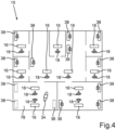
- Fig. 4 shows a schematic representation of a floor of the building in which the lighting system 10 is arranged. It can be seen that a plurality of rooms are provided in which beacons 16 are arranged, each of which emits specific identification data using respective radio signals 18. In addition, controllable devices 38 are arranged in the respective rooms and can be controlled using the method described above. Not shown in Fig. 4 the building management facility 42.
- the beacons 16 are arranged in respective lighting devices 12 (not shown), as already shown in FIG Figures 1 and 2 has been explained.
- a user is positioned with his communication terminal 34, the smartphone.
- the communication terminal 34 receives two radio signals 18 from two beacons 16 arranged in the room 78.
- an exact position of the communication terminal 34 can now be determined.
- Present the communication terminal 34 is located in room 78 as a predetermined area.
- controllable devices 38 which are not further specified and which can represent a blind, for example.
- the controllable device 38 can also be a heating or air conditioning device.
- controllable devices 38 of the room 78 can be controlled by means of the communication terminal 34.
- controllable devices 38 of the room 78 are assigned to the beacons 16 of the room 78.
- a spatial assignment is preferably provided.
- controllable devices 38 are arranged, which, however, are assigned to other beacons 16, namely the beacons 16, which are also arranged in the room 80.
- the controllable devices 38 of the room 80 cannot be controlled by the communication terminal 34, which is arranged in the room 78.
- the controllable devices 38 which cannot be controlled in the currently shown position of the communication terminal 34 in room 78, are marked with a lock symbol. In the present case, these are the controllable devices 38 outside the room 78.
- the communication terminal 34 determines its own position within the building from the specific identification data.
- one's own position is within the room 78.
- a layout plan of the lighting devices 12 is used, which contains the beacons 16, which include respective specific identification data. In this way, an exact position can be determined from a comparison of the received radio signals 18 and a field strength measurement of the radio signals 18.
- the communication terminal 34 preferably communicates with the central data processing 74, with both a wired and a wireless communication connection as well as combinations thereof being possible.
- the central data processing 74 authenticates a location of the communication terminal 34 and then forwards the control commands or the corresponding data to the corresponding controllable devices such as the blinds 38.
- wired and wireless communication connections and combinations thereof can also be used as communication channels.
- Fig. 3 shows a further embodiment for a lighting system 10, which does not fall within the wording of the claims, this embodiment being based on the previously described, according to Fig. 2 already explained, design for a lighting system 10 is based, which is why additional reference is made to the relevant statements.
- the communication terminal 34 establishes a communication connection 40 directly to the blind 38.
- the communication connection 40 is preferably designed to be wireless. However, depending on the type of communication terminal 34, it can also be wired or formed by a combination thereof.
- the communication terminal 34 can determine its own position within the specified area from the specific identification data of the beacon 16. To determine one's own position, a layout plan of the lighting device 12 or the beacons 16 arranged therein is used in the present case, in which the respective specific identification data of the Beacon 16 of the lighting devices 12, 20 are deposited. In this way, the position and thus position data can be determined from a comparison of the radio signal and a field strength measurement.
- the communication terminal 34 therefore communicates directly with the controllable device, in this case the blind 38.
- the location of the communication terminal 34 is authenticated by the communication terminal 34 itself.
Landscapes
- Engineering & Computer Science (AREA)
- Computer Networks & Wireless Communication (AREA)
- Physics & Mathematics (AREA)
- General Physics & Mathematics (AREA)
- Databases & Information Systems (AREA)
- Signal Processing (AREA)
- Circuit Arrangement For Electric Light Sources In General (AREA)
- Selective Calling Equipment (AREA)
- Mobile Radio Communication Systems (AREA)
Description
Die Erfindung betrifft ein Verfahren zum Steuern von wenigstens einer in einem vorgegebenen Bereich angeordneten steuerbaren Vorrichtung mittels eines Kommunikationsendgerätes, wobei eine Sendeeinrichtung ein Funksignal mit für die Sendeeinrichtung spezifischen Identifikationsdaten drahtlos aussendet. Darüber hinaus betrifft die Erfindung ein System zum Steuern von wenigstens einer in einem vorgegebenen Bereich angeordneten steuerbaren Vorrichtung.The invention relates to a method for controlling at least one controllable device arranged in a predetermined area by means of a communication terminal, wherein a transmitting device wirelessly transmits a radio signal with identification data specific to the transmitting device. In addition, the invention relates to a system for controlling at least one controllable device arranged in a predetermined area.
Verfahren und Systeme der gattungsgemäßen Art sowie auch Leuchteinrichtungen und Sendeeinrichtungen der gattungsgemäßen Art sind dem Grunde nach im Stand der Technik umfänglich bekannt, sodass es eines gesonderten druckschriftlichen Nachweises hierfür nicht bedarf. Mit Leuchteinrichtungen werden Räume, beispielsweise außerhalb oder auch innerhalb von Gebäuden, in vorgebbarer Weise ausgeleuchtet, um eine bestimmungsgemäße Nutzung zu ermöglichen oder zu unterstützen. Für die Leuchteinrichtungen werden zunehmend Leuchteinrichtungen eingesetzt, die neben einem Leuchtmittel, das in vorgebbarer Weise Licht abgibt, auch eine Sendeeinrichtung aufweisen, die zumindest dazu ausgebildet ist, die spezifischen Identifikationdaten drahtlos auszusenden, beispielsweise nach Art von Rundfunk. Vorzugsweise ist diese Sendeeinrichtung dazu ausgebildet, das Funksignal nach Art von Nahfunk auszusenden. Zum Aussenden des Funksignals kann ein Funk-Standard, wie zum Beispiel Bluetooth, WiFi, ZigBee oder dergleichen, genutzt werden. Eine derartige Sendeeinrichtung wird im Stand der Technik auch als "Beacon" bezeichnet.Methods and systems of the generic type as well as lighting devices and transmitting devices of the generic type are essentially well known in the prior art, so that separate printed evidence for this is not required. Lighting devices are used to illuminate rooms, for example outside or inside buildings, in a predetermined manner in order to enable or support intended use. For the lighting devices, lighting devices are increasingly being used which, in addition to a lighting device that emits light in a predeterminable manner, also have a transmitting device which is at least designed to transmit the specific identification data wirelessly, for example in the manner of broadcasting. This transmitting device is preferably designed to transmit the radio signal in the manner of local radio. A radio standard such as Bluetooth, WiFi, ZigBee or the like can be used to send the radio signal. Such a transmitting device is also referred to as a “beacon” in the prior art.
Sogenannte Beacons können mit Leuchteinrichtungen kombiniert werden, um leuchtenspezifische oder auch andere Informationen mittels ihres Signals bereitzustellen. Die Beacon-Technologie basiert auf einem Sendersystem beziehungsweise auch einem Sender-Empfänger-System. Ein Beacon (zu Deutsch auch Leuchtfeuer, Bake oder Peilsender) ist ein kleiner, meist batteriebetriebener Sender, der ein Signal in, vorzugsweise definierbaren, Zeitintervallen aussendet, beispielsweise basierend auf einem Bluetooth-Low-Energy-Standard (BLE). Das Signal eines Beacon zeichnet sich durch die spezifischen Identifikationsdaten aus, die beispielsweise eine einmalige Identifikationsnummer, englisch zum Beispiel universally unic identifier (UUID) genannt, umfasst. Beacons können dazu verwendet werden, Objekten und/oder Orten eine, insbesondere digitale, Identifikation zuzuordnen. Objekten, an denen ein Beacon installiert ist, sowie auch Orte, an denen ein Beacon, zum Beispiel an einer Wand oder einer Decke, installiert ist, können auf diese Weise von Kommunikationsendgeräten, beispielsweise Smartphones, Laptops und/oder dergleichen, im Signalfeld des Beacon identifiziert werden.So-called beacons can be combined with lighting devices in order to provide luminaire-specific or other information using their signal. Beacon technology is based on a transmitter system or a transmitter-receiver system. A beacon is a small, usually battery-operated transmitter that sends out a signal at, preferably definable, time intervals, for example based on a Bluetooth Low Energy standard (BLE). The signal of a beacon is characterized by the specific identification data, which includes, for example, a unique identification number, for example called a universally unic identifier (UUID). Beacons can be used to assign identification, in particular digital identification, to objects and/or locations. Objects where a beacon is installed, as well as places where a beacon is installed, for example on a wall or a ceiling, can in this way be used by communication devices, for example smartphones, laptops and/or the like, in the signal field of the beacon be identified.
Mit Hilfe eines Beacon kann dadurch zum Beispiel ein Ort identifiziert werden beziehungsweise eine Ortung durchgeführt werden. Durch Anordnung von einem oder mehreren Beacons in einem vorgegebenen Bereich, beispielsweise einem Gebäudebereich oder dergleichen, kann eine Art funkbasiertes Raster bereitgestellt werden, dass es einem sich in dem Bereich befindlichen Kommunikationsendgerät mittels seiner Funkschnittstelle, insbesondere BLE-Schnittstelle, sowie entsprechenden Auswertemöglichkeiten erlaubt, die eigene Position zu ermitteln. Die spezifischen Identifikationsdaten der installierten Beacons geben einem Ort dabei eine Kennung, anhand der das Kommunikationsendgerät, zumindest näherungsweise, die Position bestimmen kann. Grundsätzlich kann jedenfalls ein Sendebereich eines jeweiligen Beacon ermittelt werden. Durch geeignete Auswertung, beispielsweise unter Nutzung vorgegebener Algorithmen oder dergleichen, kann die Genauigkeit der ermittelten Position, beispielsweise unter Auswerten einer Signalstärke und/oder dergleichen, verbessert werden. Vorzugsweise kann das Kommunikationsendgerät hierfür auf Daten eines Datenspeichers zugreifen, zum Beispiel über ein Kommunikationsnetzwerk wie dem Internet und/oder dergleichen. Der Datenspeicher kann beispielsweise ein Cloud-Server oder dergleichen sein. Hier können zum Beispiel die Identifikationsdaten und eine zugeordnete Position in einer Karte vermerkt sein. Der Datenspeicher kann aber auch zumindest teilweise auf dem Kommunikationsendgerät vorhanden sein.With the help of a beacon, for example, a location can be identified or location can be carried out. By arranging one or more beacons in a predetermined area, for example a building area or the like, a type of radio-based grid can be provided that allows a communication terminal located in the area to use its radio interface, in particular BLE interface, as well as corresponding evaluation options to determine your own position. The specific identification data of the installed beacons give a location an identifier, which the communication terminal can use to determine the position, at least approximately. In principle, a transmission range of a respective beacon can be determined. Through suitable evaluation, for example using predetermined algorithms or the like, the accuracy of the determined position, for example by evaluating a signal strength and/or the like. For this purpose, the communication terminal can preferably access data from a data storage, for example via a communication network such as the Internet and/or the like. The data storage can be, for example, a cloud server or the like. Here, for example, the identification data and an assigned position can be noted on a map. However, the data memory can also be present at least partially on the communication terminal.
Kommt das Kommunikationsendgerät in die Reichweite der Sendeeinrichtung beziehungsweise des Beacon, kann es anhand der ermittelten spezifischen Identifikationsdaten somit beispielsweise über eine Serverabfrage den eigenen Standort ermitteln. Unter Nutzung weiterer Signale von weiteren Sendeeinrichtungen beziehungsweise Beacons kann mittels Ortungsalgorithmen die Genauigkeit verbessert werden, insbesondere kann aus einer Empfangsfeldstärke des jeweiligen Signals der Sendeeinrichtung beziehungsweise des Beacon ein Abstand ermittelt werden.If the communication terminal comes within the range of the transmitting device or the beacon, it can use the specific identification data determined to determine its own location, for example via a server query. By using further signals from other transmitting devices or beacons, the accuracy can be improved using positioning algorithms; in particular, a distance can be determined from a received field strength of the respective signal of the transmitting device or beacon.
Grundsätzlich können in der Lichttechnik bei Leuchteinrichtungen der gattungsgemäßen Art Sendeeinrichtungen beziehungsweise Beacons installiert sein. Dabei kann insbesondere der Vorteil genutzt werden, dass eine Lichtinstallation einen permanenten Energiezugang bereitstellen kann, um die Sendeeinrichtung beziehungsweise den Beacon mit elektrischer Energie zu versorgen. Daraus ergibt sich ein Vorteil, nämlich dass die Sendeeinrichtung beziehungsweise der Beacon keine eigene Energieversorgung in Form einer Batterie benötigt und somit entsprechender Wartungsaufwand eingespart werden kann. Darüber hinaus erlaubt es diese Ausgestaltung, dass auch Einstellungen der Sendeeinrichtung beziehungsweise des Beacon gewählt werden können, die einen hohen Energieverbrauch zur Folge haben, ohne dass dies Auswirkungen auf eine Lebensdauer des Beacon zu haben braucht. Darüber hinaus können Installationsprozesse von derartigen Sendeeinrichtungen beziehungsweise Beacons und der Lichttechnik vereinheitlicht werden.In principle, in lighting technology, transmitting devices or beacons can be installed in lighting devices of the generic type. In particular, the advantage can be used that a light installation can provide permanent energy access in order to supply the transmitting device or the beacon with electrical energy. This results in an advantage, namely that the transmitting device or the beacon does not require its own energy supply in the form of a battery and the corresponding maintenance effort can therefore be saved. In addition, this configuration allows settings of the transmitting device or the beacon to be selected that result in high energy consumption without this necessarily having an impact on the lifespan of the beacon. In addition, installation processes of such transmitting devices or beacons and lighting technology can be standardized.
Ein weiterer Vorteil ist eine definierte Arretierungsposition der Sendeeinrichtung beziehungsweise des Beacon, die vorzugsweise derart gewählt ist, dass die Sendeeinrichtung beziehungsweise der Beacon vor Manipulation geschützt ist. Dadurch kann einem Ort somit eine zuverlässig sichere Kennung zugeordnet werden.Another advantage is a defined locking position of the transmitting device or the beacon, which is preferably selected such that the transmitting device or the beacon is protected from manipulation. This means that a location can be assigned a reliably secure identifier.
Ein Überblick über Nutzungspotenziale der Integration einer Sendeeinrichtung beziehungsweise eines Beacon in eine Leuchteinrichtung kann folgender Aufzählung entnommen werden:
- Es kann die Energieversorgung der Lichtinstallation anstelle einer Energieversorgung durch eine Batterie genutzt werden, um zum Beispiel Lebenszykluskosten der Sendeeinrichtung beziehungsweise des Beacon zu reduzieren.
- Die elektrische Energieversorgung der Leuchteinrichtung kann genutzt werden, um Sendeparameter des Signals der Sendeeinrichtung beziehungsweise des Beacon an einen Dienst und nicht an eine verfügbare Restenergiemenge beziehungsweise Parameter der Batterie anzupassen. Beispielsweise erzeugen häufige Sendezyklen eine hohe Genauigkeit eines jeweiligen Dienstes, jedoch führt dies auch zu einem erhöhten Energieverbrauch.
- Der Austausch der Batterie konventioneller Sendeeinrichtungen beziehungsweise Beacons birgt Risiken, nämlich beispielsweise im Hinblick auf Fehler bei der Handhabung.
- Eine Nicht-Verfügbarkeit von Diensten kann durch eine unterbrechungsfreie Energieversorgung der Sendeeinrichtung beziehungsweise des Beacon vermieden werden.
- Ein Installationsort unterhalb einer Decke kann vorteilhaft für eine Signalausbreitung des Signals der Sendeeinrichtung beziehungsweise des Beacon sein.
- Ein Installationsort unterhalb der Decke kann das Gesamtsystem robuster gegen Störungen beziehungsweise Abschattungen durch andere Objekte auf Höhe einer Flurebene im Gegensatz zu einer Installation der Sendeeinrichtung beziehungsweise des Beacon selbst auf Höhe der Flurebene machen.
- Die Sendeeinrichtung beziehungsweise der Beacon kann vor Manipulationen beziehungsweise Fremdzugriffen, ob versehentlich oder mutwillig, geschützt werden.
- Ein System sowie auch Dienste wie zum Beispiel Ortungsdienste oder dergleichen können als Gesamtsystem "aus einer Hand" angeboten werden.
- Es besteht darüber hinaus die Möglichkeit zur Nutzung eines sicheren Kommunikationsnetzwerkes des Systems, um beispielsweise die Sendeeinrichtung beziehungsweise den Beacon zu konfigurieren oder die Sendeeinrichtungen beziehungsweise die Beacons untereinander zu vernetzen.
- Eine Vereinheitlichung von Installationsprozessen von Sendeeinrichtungen beziehungsweise Beacons und dem System kann ermöglicht werden.
- Weiterhin besteht die Möglichkeit zur Kopplung zu weiteren Systemelementen einer peripheren Gebäudeinfrastruktur, insbesondere steuerbaren Vorrichtungen, über das Kommunikationsnetzwerk des Systems, zum Beispiel zu Elementen der Sicherheitstechnik oder dergleichen.
- Es kann ein optisch ansprechendes System bereitgestellt werden, da die Sendeeinrichtung beziehungsweise der Beacon nicht sichtbar in der jeweiligen Leuchteinrichtung beziehungsweise im System angeordnet sein kann.
- The energy supply of the lighting installation can be used instead of an energy supply from a battery, for example to reduce life cycle costs of the transmitting device or the beacon.
- The electrical energy supply of the lighting device can be used to adapt transmission parameters of the signal of the transmitting device or of the beacon to a service and not to an available residual amount of energy or parameters of the battery. For example, frequent transmission cycles produce a high level of accuracy for a respective service, but this also leads to increased energy consumption.
- Replacing the battery of conventional transmitting devices or beacons involves risks, for example with regard to errors in handling.
- Non-availability of services can be avoided by providing an uninterrupted power supply to the transmitting device or the beacon.
- An installation location below a ceiling can be advantageous for signal propagation of the signal from the transmitting device or the beacon.
- An installation location below the ceiling can make the entire system more robust against interference or shadowing from other objects at the level of a hallway, in contrast to installing the transmitter or the beacon itself at the level of the hallway.
- The transmitting device or the beacon can be protected from manipulation or unauthorized access, whether accidental or deliberate.
- A system as well as services such as location services or the like can be offered as a complete system “from a single source”.
- There is also the possibility of using a secure communication network of the system, for example to configure the transmitting device or the beacon or to network the transmitting devices or the beacons with one another.
- A standardization of installation processes of transmitting devices or beacons and the system can be made possible.
- There is also the possibility of coupling to other system elements of a peripheral building infrastructure, in particular controllable devices, via the communication network of the system, for example to elements of security technology or the like.
- A visually appealing system can be provided since the transmitting device or the beacon cannot be arranged visibly in the respective lighting device or in the system.
Ein Beacon kann als Sendeeinrichtung in eine Leuchteinrichtung eines Systems integriert sein. Das System kann eine Mehrzahl von Leuchteinrichtungen umfassen. Die Leuchteinrichtung umfasst neben dem Beacon ein oder mehrere Leuchtmittel, die die gewünschte Beleuchtungsfunktion bereitstellen. Der Beacon und die Leuchteinrichtung stehen vorzugsweise in Kommunikationsverbindung miteinander. Der Beacon ist vorzugsweise in die Leuchteinrichtung integriert angeordnet. Es braucht also für den Beacon kein separates Gehäuse vorgesehen zu werden. Dadurch kann der Beacon zugleich geschützt angeordnet werden, so dass die bestimmungsgemäße Funktion mit hoher Zuverlässigkeit bereitgestellt werden kann. Weitere Leuchteinrichtungen des Systems sind vorzugsweise identisch zur Leuchteinrichtung ausgebildet.A beacon can be integrated into a lighting device of a system as a transmitting device. The system can include a plurality of lighting devices. In addition to the beacon, the lighting device includes one or more lighting devices that provide the desired lighting function. The beacon and the lighting device are in place preferably in communication connection with each other. The beacon is preferably arranged integrated into the lighting device. There is therefore no need to provide a separate housing for the beacon. This allows the beacon to be arranged in a protected manner at the same time, so that the intended function can be provided with high reliability. Further lighting devices of the system are preferably designed identically to the lighting device.
Der Beacon ist ausgebildet, ein Signal, nämlich das Funksignal, mit für den Beacon spezifischen Identifikationsdaten drahtlos auszusenden. Vorzugsweise erfolgt die Aussendung per Funk unter Nutzung eines BLE-Standards. Der Beacon umfasst vorzugsweise ferner eine Steuereinheit, die eine Rechnereinheit sowie eine Speichereinheit umfasst. In der Speichereinheit ist ein ablauffähiges Rechnerprogramm gespeichert, welches für die Rechnereinheit bereitsteht, so dass mittels der Rechnereinheit eine vorgegebene Steuerfunktion erreicht werden kann.The beacon is designed to wirelessly emit a signal, namely the radio signal, with identification data specific to the beacon. The transmission is preferably carried out via radio using a BLE standard. The beacon preferably further comprises a control unit which comprises a computer unit and a storage unit. An executable computer program is stored in the storage unit and is available for the computer unit, so that a predetermined control function can be achieved using the computer unit.
Der Beacon kann ferner über eine Kommunikationsverbindung an weitere lokale Beacons angeschlossen sein. Die Kommunikationsverbindung ist vorzugsweise ebenfalls als drahtlose Kommunikationsverbindung, insbesondere nach dem BLE-Standard, ausgebildet. Sie kann aber auch zumindest teilweise leitungsgebunden sein. Die Kommunikationsverbindung zwischen dem Beacon und den weiteren Beacons ist zum Beispiel bidirektional. Sie kann aber auch zumindest teilweise unidirektional sein.The beacon can also be connected to other local beacons via a communication connection. The communication connection is preferably also designed as a wireless communication connection, in particular according to the BLE standard. But it can also be at least partially wired. The communication connection between the beacon and the other beacons is, for example, bidirectional. But it can also be at least partially unidirectional.
Darüber hinaus kann der Beacon über eine weitere Kommunikationsverbindung an eine Dateninfrastruktureinrichtung angeschlossen sein. Die Dateninfrastruktureinrichtung kann der Steuerung des Systems, hier insbesondere der Leuchteinrichtungen des Systems, dienen. Die Infrastruktureinrichtung kann zum Beispiel das Internet oder aber auch ein zentraler Dienste-Server sein. Die Dateninfrastruktureinrichtung kann ferner zur Steuerung und/oder Übermittlung von Daten dienen. Der lokale Beacon der Leuchteinrichtung kann als reine Sendeeinrichtung nach Art eines Rundfunkbetriebs oder auch als kombinierte Sende-Empfangs-Einrichtung ausgebildet sein.In addition, the beacon can be connected to a data infrastructure device via another communication connection. The data infrastructure device can serve to control the system, here in particular the lighting devices of the system. The infrastructure facility can do this, for example Internet or a central service server. The data infrastructure device can also be used to control and/or transmit data. The local beacon of the lighting device can be designed as a pure transmitting device in the manner of a broadcasting operation or as a combined transmitting-receiving device.
Das Signal des Beacon kann mittels Kommunikationsendgeräten, wie zum Beispiel ein Smartphone, ein LAPTOP und/oder dergleichen, empfangen werden.The beacon signal can be received using communication terminals such as a smartphone, a LAPTOP and/or the like.
Gemäß einem Nutzungsbeispiel können Nutzer beziehungsweise Geräte gegebenenfalls die Herausforderung haben, sich innerhalb eines Bereichs orientieren zu müssen, navigieren oder andere lokale digitale Dienste auffinden beziehungsweise nutzen zu wollen, wie zum Beispiel Apps, App-Funktionen, Google-Maps, Lightify, Lichtsteuerung und/oder dergleichen. Das System mit integrierten Beacons in einem vorgegebenen Bereich kann für diese Nutzungspotenziale zu einem Ortungsbeziehungsweise Orientierungssystem werden. Mit einer damit realisierbaren Selbstortung des Kommunikationsendgerätes können nun Dienste bereitgestellt werden, beispielsweise eine Navigation, eine Bereitstellung von ortsspezifischen Informationen und/oder dergleichen.According to an example of use, users or devices may have the challenge of having to orient themselves within an area, navigate or want to find or use other local digital services, such as apps, app functions, Google Maps, Lightify, lighting control and/ or similar. The system with integrated beacons in a specified area can become a location or orientation system for these potential uses. With self-location of the communication terminal that can be realized in this way, services can now be provided, for example navigation, provision of location-specific information and/or the like.
Ein Aspekt der Beacon-Technologie ist die Möglichkeit zur Konfiguration typischer Parameter, wie beispielsweise eine Signalstärke, ein Sendeintervall und/oder dergleichen des Beacon. Mit unterschiedlichen Konfigurationen können verschiedene Anwendungsszenarien individuell unterstützt werden. Wenn zum Beispiel eine hohe Servicequalität in Bezug auf eine genaue Lokalisierung in kurzen Abständen gewünscht ist, beispielsweise bei einer Indoor-Navigation, können zum Beispiel sehr kurze Sendeintervalle zu konfigurieren sein.One aspect of beacon technology is the ability to configure typical parameters, such as a signal strength, a transmission interval and/or the like, of the beacon. Different application scenarios can be individually supported with different configurations. If, for example, a high quality of service is desired with regard to precise localization at short intervals, for example in indoor navigation, very short transmission intervals can be configured, for example.
Insbesondere bei digital gesteuerten Systemen, zum Beispiel unter Nutzung von Digital Addressable Lighting Interfaces (DALI), sollte eindeutig identifiziert werden können, welches Leuchtmittel beziehungsweise welche Leuchteinrichtung an welchem Ort angeordnet ist, um mittels digitaler Lichtsteuerung eine exakte Ansteuerung der Leuchteinrichtungen beziehungsweise deren Leuchtmittel in einem bestimmten Bereich zu ermöglichen. Die Leuchteinrichtungen benötigen hierzu eine eindeutige Adresse, welche ihre Position in einem vorgegebenen Bereich wiederspiegelt. Der Fachmann nennt eine derartige Zuordnung von Leuchteinrichtungen zu entsprechenden Positionen beziehungsweise Adressen "kommissionieren". Hierbei müssen mehrere Informationen zusammengeführt werden, nämlich die eindeutigen Identifikationsdaten einer jeweiligen Leuchteinrichtung, ein Installationsort der jeweiligen Leuchteinrichtung in einem vorgegebenen Bereich, das heißt, eine physikalische Adresse der Leuchteinrichtung, sowie eine Kennung der Leuchteinrichtung, das heißt, zum Beispiel ihre digitale Adresse.Especially in digitally controlled systems, for example using Digital Addressable Lighting Interfaces (DALI), it should be possible to clearly identify which one Lamps or which lighting device is arranged at which location in order to enable precise control of the lighting devices or their lamps in a specific area by means of digital light control. For this purpose, the lighting devices need a unique address that reflects their position in a specified area. The expert calls such an assignment of lighting devices to corresponding positions or addresses “picking”. In this case, several pieces of information must be brought together, namely the unique identification data of a respective lighting device, an installation location of the respective lighting device in a predetermined area, that is, a physical address of the lighting device, and an identifier of the lighting device, that is, for example its digital address.
Die digitale Adresse einer Leuchteinrichtung kann in der Regel über Powerline-Kommunikation oder eine ähnliche leistungsbasierte Kommunikationsverbindung über die Energieverteilung an eine Steuerung beziehungsweise Datenverarbeitung übermittelt werden. Die Leuchteinrichtung beziehungsweise ein Vorschaltgerät der Leuchteinrichtung kann sich somit mit ihrer digitalen Adresse bei der Steuerung anmelden. Damit ist jedoch noch nicht die Information verfügbar, an welcher physikalischen Stelle im vorgegebenen Bereich die Leuchteinrichtung tatsächlich angeordnet ist. Diese Information ist aber erforderlich, wenn nur ein definierter Bereich beleuchtet werden soll, beispielsweise nur ein Besprechungsraum oder ein Teil davon oder dergleichen.The digital address of a lighting device can usually be transmitted to a controller or data processor via powerline communication or a similar power-based communication connection via the energy distribution. The lighting device or a ballast of the lighting device can thus register with the control with its digital address. However, this does not yet provide information about the physical location at which the lighting device is actually located in the specified area. However, this information is necessary if only a defined area is to be illuminated, for example only a meeting room or a part of it or the like.
Derzeit können Leuchteinrichtungen beziehungsweise Leuchtmittel und gleichzeitig deren Standort in der Regel nicht ohne weiteres elektronisch identifiziert werden. Typischerweise kann nur über einen Aufkleber oder eine Aufprägung erkannt werden, beispielsweise auf einem Gehäuse der Leuchteinrichtung, um was für einen Typ der Leuchteinrichtung beziehungsweise des Leuchtmittels es sich handelt. Eine andere aufwendige Möglichkeit ist es, jede digital angemeldete Leuchteinrichtung im Rahmen des Systems einzeln blinken zu lassen und manuell eine Positionsinformation in einem Layout zu markieren.Currently, lighting devices or lamps and their location cannot generally be easily identified electronically. Typically, it can only be recognized via a sticker or an imprint, for example on a housing the lighting device, what type of lighting device or light source it is. Another complex option is to have each digitally registered lighting device flash individually within the system and to manually mark position information in a layout.
Um Leuchteinrichtungen und/oder Leuchtmittel im Rahmen des Systems effizient mit einem Lichtmanagementsystem (LMS) zu verbinden, wäre es vorteilhaft, eine oder mehrere elektronische beziehungsweise digitale Identifikationsdaten zur Erkennung des Gesamtsystems oder einzelner Komponenten des Gesamtsystems zur Verfügung zu haben.In order to efficiently connect lighting devices and/or lamps as part of the system to a light management system (LMS), it would be advantageous to have one or more electronic or digital identification data available for recognizing the entire system or individual components of the overall system.
Eine spezifische Problematik besteht ferner darin, dass in der Regel in einem Installationsplan Positionen der Leuchteinrichtungen beziehungsweise Leuchtmittel für einen Beleuchtungsbereich als zum Beispiel vorgegebenen Bereich beziehungsweise Service-Bereich festgelegt werden. Dies gibt einem Installateur vor, welche der angelieferten beziehungsweise kommissionierten Leuchteinrichtungen, zum Beispiel bezüglich eines Leuchtentyps oder dergleichen, an welcher Position des Bereichs, beispielsweise des Gebäudes, entsprechend dem Installationsplan angeordnet werden sollen.A further specific problem is that positions of the lighting devices or lamps for a lighting area are usually defined in an installation plan, for example as a predetermined area or service area. This specifies to an installer which of the delivered or commissioned lighting devices, for example with regard to a type of lamp or the like, should be arranged at which position in the area, for example the building, according to the installation plan.
Ortsbezogene Dienste beziehungsweise Services, wie zum Beispiel Navigation eines Nutzers oder dergleichen, mittels Beacon sollen dem Nutzer in einem vorgegebenen Bereich, vorzugsweise permanent und ohne Einschränkung, zur Verfügung stehen. Dies erfordert neben einer unterbrechungsfreien elektrischen Energieversorgung auch eine regelmäßige Wartung beziehungsweise gegebenenfalls auch Aktualisierung von Rechnerprogrammen wie zum Beispiel der Firmware oder dergleichen. Insbesondere Firmware-Updates von technischen Systemen sind von hoher Bedeutung. Sie dienen in der Regel einer Fehlerbeseitigung, einer Leistungsoptimierung sowie gegebenenfalls auch einer Funktionserweiterung des technischen Systems. So können zum Beispiel Fehler, sogenannte Bugs, behoben werden, wodurch die Zuverlässigkeit gesteigert werden kann. Darüber hinaus können Sicherheitslücken geschlossen oder technische Funktionen des Systems nachträglich frei- oder abgeschaltet werden. Somit erklärt sich ein hoher Bedarf, Firmware-Updates in regelmäßigen, insbesondere situationsspezifischen, Abständen durchzuführen.Location-based services or services, such as navigation of a user or the like, using beacons should be available to the user in a specified area, preferably permanently and without restrictions. In addition to an uninterrupted electrical energy supply, this also requires regular maintenance or, if necessary, updating of computer programs such as firmware or the like. Firmware updates of technical systems are particularly important. They usually serve to eliminate errors, optimize performance and, if necessary, expand the functionality of the technical system. For example, errors can So-called bugs can be fixed, which can increase reliability. In addition, security gaps can be closed or technical functions of the system can be subsequently activated or deactivated. This explains the high need to carry out firmware updates at regular, particularly situation-specific, intervals.
Die folgenden Sachverhalte können bei der Anwendung von Beacons zu beachten sein:
- Derzeit werden für die Energieversorgung der Beacons Batterien eingesetzt. Durch die Notwendigkeit, diese Batterien in regelmäßigen Zyklen zu wechseln, ergibt sich ein hoher Aufwand sowie entsprechend hohe Lebenszykluskosten für den jeweiligen Beacon.
- Eine hohe Service-Qualität, beispielsweise eine hohe Ortungsgenauigkeit, eine hohe Reichweite, ein kurzes Sendeintervall und/oder dergleichen, führt in der Regel zu einem entsprechend hohen Bedarf an elektrischer Energie für die Sendeeinrichtung beziehungsweise den Beacon, sodass die Batterie bei einem batteriebetriebenen Beacon bereits nach kurzer Zeit, zum Beispiel nach einem Monat, ausgetauscht werden muss, um den bestimmungsgemäßen Betrieb darüber hinaus aufrechterhalten zu können.
- Jeder Austausch einer Batterie birgt zudem das Risiko, dass die Funktionalität des Ortungssystems durch eine Positionsveränderung oder eine falsche Handhabung des Beacon nachteilig beeinflusst werden kann.
- Darüber hinaus besteht das Problem, dass ein Betreiber einen Energiemangel des Beacon nicht bemerkt beziehungsweise den Beacon nicht wieder auffindet, wenn der Beacon keine ausreichende Restenergiemenge hat, um sein Funksignal aussenden zu können.
- Die Dienste des Beacon zum Beispiel in Bezug auf Navigation oder dergleichen, sollen den Nutzern jedoch vorzugsweise permanent zur Verfügung gestellt werden können. Hierfür ist eine unterbrechungsfreie Energieversorgung wünschenswert.
- Eine Anbringung beziehungsweise eine Installation der Beacons an beziehungsweise in oder als Teil der Leuchteinrichtung würde es gegenüber einem batteriebetriebenen Beacon ermöglichen, die Energieversorgung der Leuchteinrichtung, zum Beispiel ein Vorschaltgerät des Leuchtmittels oder dergleichen, für seine eigene Energieversorgung des Beacon zu nutzen und somit die Batterie des Beacon zumindest teilweise zu substituieren und den damit verbundenen Problemstellungen entgegenzuwirken.
- Batteries are currently used to power the beacons. The need to change these batteries at regular cycles results in a lot of effort and correspondingly high life cycle costs for the respective beacon.
- A high service quality, for example a high location accuracy, a long range, a short transmission interval and/or the like, usually leads to a correspondingly high requirement for electrical energy for the transmitting device or the beacon, so that the battery is already in use in a battery-operated beacon must be replaced after a short period of time, for example after a month, in order to be able to continue to operate as intended.
- Every replacement of a battery also carries the risk that the functionality of the tracking system can be adversely affected by a change in position or incorrect handling of the beacon.
- In addition, there is the problem that an operator does not notice a lack of energy in the beacon or does not find the beacon again if the beacon does not have a sufficient amount of remaining energy to be able to send out its radio signal.
- However, the beacon services, for example in relation to navigation or the like, should preferably be made available to users permanently can. An uninterrupted energy supply is desirable for this.
- Attaching or installing the beacons on or in or as part of the lighting device would make it possible, compared to a battery-operated beacon, to use the energy supply of the lighting device, for example a ballast of the lamp or the like, for its own energy supply to the beacon and thus the battery of the To at least partially replace Beacon and counteract the associated problems.
In einem vorgegebenen Bereich, in dem häufig auch wenigstens ein Beacon angeordnet ist, sind häufig auch steuerbare technische Infrastrukturelemente beziehungsweise Vorrichtungen angeordnet, zum Beispiel die Leuchteinrichtung, eine Klimaanlage, Jalousien und/oder dergleichen. Diese steuerbaren Vorrichtungen lassen sich zunehmend neben herkömmlichen Bedienelementen, beispielsweise manuell betätigbaren Tastern oder Schaltern, mittels Kommunikationsendgeräten wie Smartphones, Tablets und/oder dergleichen steuern. Dabei erfolgt die Ansteuerung abhängig von der jeweiligen steuerbaren Vorrichtung über unterschiedlichste Kommunikationsschnittstellen, wie zum Beispiel WLAN, Bluetooth, ZigBee, DALI-Bus und/oder dergleichen.Controllable technical infrastructure elements or devices are often also arranged in a predetermined area, in which at least one beacon is often arranged, for example the lighting device, an air conditioning system, blinds and/or the like. In addition to conventional operating elements, for example manually operated buttons or switches, these controllable devices can increasingly be controlled using communication terminals such as smartphones, tablets and/or the like. The control takes place depending on the respective controllable device via a wide variety of communication interfaces, such as WLAN, Bluetooth, ZigBee, DALI bus and/or the like.
So offenbart die
Mit zunehmender Anzahl der zu steuernden Vorrichtungen, insbesondere in einem Gebäude oder einem entsprechenden Service-Areal kann hierbei ein unübersichtliches Gesamtsystem die Folge sein. Im Sinne einer hohen Benutzungsfreundlichkeit ist es gewünscht, dem Nutzer von seinem aktuellen Standort aus die im nahen Umfeld befindlichen steuerbaren Vorrichtungen zur Steuerung vorzuschlagen. Hierzu benötigt das Kommunikationsendgerät zusätzliche ortsbezogene Daten. Weiterhin erweist es sich als gewünscht beziehungsweise sogar erforderlich, sicherheitskritische Infrastruktur-Vorrichtungen vor unbefugtem Zugriff zu schützen.As the number of devices to be controlled increases, particularly in a building or a corresponding service area, the result can be a confusing overall system. In the interests of a high level of user-friendliness, it is desirable to suggest to the user from his current location the controllable devices in the immediate vicinity for control. Needed for this the communication terminal receives additional location-related data. Furthermore, it turns out to be desired or even necessary to protect safety-critical infrastructure devices from unauthorized access.
Der Erfindung liegt somit die Aufgabe zugrunde, ein Verfahren zum Steuern von einer steuerbaren Vorrichtung sowie ein System hierfür zu verbessern.The invention is therefore based on the object of improving a method for controlling a controllable device and a system for this.
Als Lösung werden mit der Erfindung ein Verfahren sowie ein System gemäß den unabhängigen Ansprüchen vorgeschlagen.As a solution, the invention proposes a method and a system according to the independent claims.
Weitere vorteilhafte Ausgestaltungen ergeben sich anhand von Merkmalen der abhängigen Ansprüche.Further advantageous refinements result from features of the dependent claims.
Bezüglich eines gattungsgemäßen Verfahrens wird insbesondere vorgeschlagen, dass das Verfahren die Schritte umfasst:
- Zuordnen der wenigstens einen steuerbaren Vorrichtung zu der Sendeeinrichtung,
- Empfangen des Funksignals mittels des Kommunikationsendgerätes,
- Auswerten des Funksignals zum Erfassen der spezifischen Identifikationsdaten,
- Ermitteln der wenigstens einen der Sendeeinrichtung zugeordneten steuerbaren Vorrichtung anhand der erfassten spezifischen Identifikationsdaten,
- Herstellen einer Kommunikationsverbindung zwischen der wenigstens einen Vorrichtung und dem Kommunikationsendgerät und
- Übermitteln von einem Steuerbefehl entsprechenden Daten zum Steuern der wenigstens einen Vorrichtung und/oder der Sendeeinrichtung selbst.
- Assigning the at least one controllable device to the transmitting device,
- Receiving the radio signal using the communication terminal,
- Evaluating the radio signal to record the specific identification data,
- Determining the at least one controllable device assigned to the transmitting device based on the recorded specific identification data,
- Establishing a communication connection between the at least one device and the communication terminal and
- Transmitting data corresponding to a control command for controlling the at least one device and/or the transmitting device itself.
In Bezug auf ein gattungsgemäßes System wird insbesondere vorgeschlagen, dass das System aufweist:
- die steuerbare Vorrichtung,
- eine Sendeeinrichtung, die ein Funksignal mit für die Sendeeinrichtung spezifischen Identifikationsdaten drahtlos aussendet, wobei die wenigstens eine steuerbare Vorrichtung der Sendeeinrichtung zugeordnet ist,
- ein Kommunikationsendgerät zum Steuern der steuerbaren Vorrichtung und/oder der Sendeeinrichtung selbst, wobei das Kommunikationsendgerät ausgebildet ist, das Funksignal zu empfangen und zum Erfassen der spezifischen Identifikationsdaten auszuwerten,
- eine Ermittlungseinheit zum Ermitteln der wenigstens einen der Sendeeinrichtung zugeordneten steuerbaren Vorrichtung anhand der erfassten spezifischen Identifikationsdaten,
- wobei eine Kommunikationsverbindung zwischen der wenigstens einen Vorrichtung und dem Kommunikationsendgerät herstellbar ist, um einem Steuerbefehl entsprechende Daten zum Steuern der wenigstens einen steuerbaren Vorrichtung und/oder der Sendeeinrichtung selbst zu übermitteln.
- the controllable device,
- a transmitting device which wirelessly transmits a radio signal with identification data specific to the transmitting device, the at least one controllable device being assigned to the transmitting device,
- a communication terminal for controlling the controllable device and/or the transmitting device itself, the communication terminal being designed to receive the radio signal and to evaluate it to acquire the specific identification data,
- a determination unit for determining the at least one controllable device assigned to the transmitting device based on the recorded specific identification data,
- wherein a communication connection can be established between the at least one device and the communication terminal in order to transmit data corresponding to a control command for controlling the at least one controllable device and / or the transmitting device itself.
Die Erfindung basiert auf der Erkenntnis, dass durch die Einbeziehung eines lokalen Beacon gattungsgemäße Verfahren und Systeme erheblich verbessert werden können. Dadurch, dass mit dem Beacon eine lokale Positionierung des Kommunikationsendgerätes erreicht werden kann, kann nicht nur die Nutzerfreundlichkeit verbessert werden, sondern es kann zugleich auch die Sicherheit erhöht werden. Durch die Erfindung ist es nämlich möglich, die Bedienbarkeit von steuerbaren Vorrichtungen auf den vorgegebenen Bereich zu begrenzen. Dadurch kann vermieden werden, dass von außerhalb des vorgegebenen Bereichs die steuerbaren Vorrichtungen in unerwünschter Weise gesteuert werden können. Um hierbei die erforderliche Zuverlässigkeit im bestimmungsgemäßen Betrieb erreichen zu können, ist aus diesem Grund die Sendeeinrichtung beziehungsweise der Beacon in beziehungsweise an der Leuchteinrichtung angeordnet, die sich ebenfalls im vorgegebenen Bereich befindet.The invention is based on the knowledge that generic methods and systems can be significantly improved by including a local beacon. Because the beacon can be used to achieve local positioning of the communication terminal, not only can user-friendliness be improved, but security can also be increased at the same time. The invention makes it possible to limit the operability of controllable devices to the specified range. This can prevent the controllable devices from being controlled in an undesirable manner from outside the predetermined range. In order to be able to achieve the required reliability in intended operation, the transmitting device or the beacon is arranged in or on the lighting device, which is also located in the specified area.
Die Sendeeinrichtung beziehungsweise der Beacon kann dadurch Teil einer Lichtinstallation werden, die in dem Service-Areal angeordnet ist. Vorzugsweise umfasst der vorgegebene Bereich zumindest einen Teil des Service-Areals. Das Service-Areal kann zum Beispiel ein Bürogebäude aber auch ein Freigelände und/oder dergleichen sein.The transmitting device or the beacon can thereby become part of a light installation that is arranged in the service area. Preferably, the predetermined area includes at least part of the service area. The service area can be, for example, an office building but also an outdoor area and/or the like.
Der vorgegebene Bereich ist vorzugsweise durch eine Kommunikationsreichweite des jeweiligen Kommunikationsendgerätes mit der Sendeeinrichtung beziehungsweise dem Beacon bestimmt. Der vorgegebene Bereich kann beispielsweise auch durch die Leuchteinrichtung bestimmt beziehungsweise vorgegeben sein.The predetermined area is preferably determined by a communication range of the respective communication terminal with the transmitting device or the beacon. The predetermined area can also be determined or predetermined, for example, by the lighting device.
Auch wenn sich das Steuern auf die steuerbare Vorrichtung bezieht, soll im Rahmen dieser Offenbarung auch ein Steuern der Sendeeinrichtung selbst mit umfasst sein. Das Steuern kann sich daher sowohl auf die Vorrichtung als auch auf die Sendeeinrichtung oder auch auf beide beziehen, insbesondere natürlich wenn die Sendeeinrichtung und die Vorrichtung zum Beispiel zumindest teilweise einstückig miteinander ausgebildet sind.Even if the control relates to the controllable device, control of the transmitting device itself should also be included within the scope of this disclosure. The control can therefore relate to both the device and the transmitting device or both, particularly of course if the transmitting device and the device are, for example, at least partially formed in one piece with one another.
So kann vorgesehen sein, dass das Steuern auch ein Steuern der Sendeeinrichtung umfasst. Das Steuern der Sendeeinrichtung kann zum Beispiel genutzt werden, um die spezifischen Identifikationsdaten gegebenenfalls anpassen zu können, beispielsweise im Zusammenhang mit einer Kommissionierung oder dergleichen, insbesondere aber auch unter besonderer Berücksichtigung der steuerbaren Vorrichtung. So können unter anderem sendeeinrichtungsspezifische Steuer- und/oder Konfigurationsdaten, wie zum Beispiel Universally Unique Identifier (UUID), major ID, minor ID, Uniform Resource Locator (URL), Sensorinformationen und/oder dergleichen, allgemeine weitere Content-Daten, Sendeintervalle, Sendeleistung, Daten über die Sende- und/oder Empfangsleistung und/oder dergleichen. Dabei kann vorgesehen sein, dass ein Zugriff auf die spezifischen Identifikationsdaten geschützt sein kann, zum Beispiel indem ein Zugriff eine Authentifizierung erfordert.It can thus be provided that the controlling also includes controlling the transmitting device. Controlling the transmitting device can be used, for example, to be able to adapt the specific identification data if necessary, for example in connection with picking or the like, but in particular also with special consideration of the controllable device. For example, transmitter-specific control and/or configuration data, such as Universally Unique Identifier (UUID), major ID, minor ID, Uniform Resource Locator (URL), sensor information and/or the like, general other content data, transmission intervals, transmission power , data about the transmission and/or reception power and/or the like. This can be provided be that access to the specific identification data can be protected, for example by requiring access to authentication.
Darüber hinaus kann das Steuern der Sendeeinrichtung auch dazu dienen, die steuerbare Vorrichtung unmittelbar zu steuern. Zu diesem Zweck kann die steuerbare Vorrichtung steuerungstechnisch mit der Sendeeinrichtung beziehungsweise dem Beacon gekoppelt sein. Vorteilhaft kann diese Weiterbildung auch dann zum Einsatz kommen, wenn der Sendeeinrichtung beziehungsweise dem Beacon mehr als eine steuerbare Vorrichtung zugeordnet ist. Dem Grunde nach braucht der Sendeeinrichtung beziehungsweise dem Beacon nämlich nicht nur eine einzige steuerbare Vorrichtung zugeordnet zu sein, sondern es können auch mehrere steuerbare Vorrichtungen der Sendeeinrichtung beziehungsweise dem Beacon zugeordnet sein, insbesondere wenn sie im gleichen vorgegebenen Bereich angeordnet sind.In addition, controlling the transmitting device can also serve to directly control the controllable device. For this purpose, the controllable device can be coupled in terms of control technology to the transmitting device or the beacon. This development can also be used advantageously if more than one controllable device is assigned to the transmitting device or the beacon. Basically, the transmitting device or the beacon not only needs to be assigned a single controllable device, but several controllable devices can also be assigned to the transmitting device or the beacon, especially if they are arranged in the same predetermined area.
Das Herstellen der Kommunikationsverbindung zwischen dem Kommunikationsendgerät und der steuerbaren Vorrichtung kann somit auch umfassen, dass die Daten an die Sendeeinrichtung beziehungsweise den Beacon übermittelt werden und diese eine entsprechende Steuerung der wenigstens einen steuerbaren Vorrichtung vornimmt. Darüber hinaus kann vorgesehen sein, dass die Sendeeinrichtung beziehungsweise der Beacon aus den empfangenen Daten den entsprechenden Steuerbefehl ermittelt und diesen zum Steuern der steuerbaren Vorrichtung anwendet oder an diese weiterleitet.Establishing the communication connection between the communication terminal and the controllable device can therefore also include the data being transmitted to the transmitting device or the beacon and the latter carrying out a corresponding control of the at least one controllable device. In addition, it can be provided that the transmitting device or the beacon determines the corresponding control command from the received data and uses it to control the controllable device or forwards it to it.
Die Sendeeinrichtung beziehungsweise der Beacon können nicht nur als reine Sendeeinrichtung zum Aussenden des Funksignals nach Art von Rundfunk dienen, sie können darüber hinaus auch eine Empfangseinheit aufweisen, die es ermöglicht, vorzugsweise per Funk, insbesondere per Nahfunk, ein Kommunikationssignal zu empfangen, beispielsweise vom Kommunikationsendgerät, welches sich in Kommunikationsreichweite zur Sendeeinrichtung beziehungsweise zum Beacon befindet, wodurch dann eine Sende-Empfangs-Einrichtung gebildet wird. Dadurch ist es möglich, zusätzliche Funktionalität bereitzustellen, beispielsweise indem sendeeinrichtungsseitig beziehungsweise beaconseitig das Kommunikationssignal ausgewertet wird und aufgrund der hierdurch gewonnenen Daten ergänzend zum Funksignal weitere Daten ausgesendet werden können, beispielsweise in Bezug auf eine Funktion der Beleuchtungseinrichtung, bestückte Leuchtmittel der Leuchteinrichtung, verfügbare Datenformate und/oder dergleichen.The transmitting device or the beacon can not only serve as a pure transmitting device for sending out the radio signal in the manner of broadcasting, they can also have a receiving unit which makes it possible to receive a communication signal, for example from the communication terminal, preferably by radio, in particular by local radio , which is within communication range of the transmitting device or to the beacon, which then forms a transceiver device. This makes it possible to provide additional functionality, for example by evaluating the communication signal on the transmission device side or beacon side and, based on the data obtained thereby, further data can be sent out in addition to the radio signal, for example with regard to a function of the lighting device, equipped lamps of the lighting device, available data formats and /or similar.
Nahfunk meint vorliegend insbesondere, dass mittels einer Funkverbindung eine Kommunikationsreichweite in einem Bereich von wenigen Metern, beispielsweise in einem Bereich von etwa 0,5 m bis etwa 25 m, vorzugsweise in einem Bereich von etwa 1 m bis etwa 10 m, besonders bevorzugt in einem Bereich von etwa 1,5 m bis etwa 5 m erreicht werden kann.In the present case, local radio means in particular that by means of a radio connection a communication range in a range of a few meters, for example in a range from approximately 0.5 m to approximately 25 m, preferably in a range from approximately 1 m to approximately 10 m, particularly preferably in a Range from about 1.5 m to about 5 m can be achieved.
Dabei erlaubt es die Erfindung, aufgrund der Anordnung der Sendeeinrichtung beziehungsweise des Beacon eine bestehende Energie- und/oder Kommunikationsschnittstelle einer Lichtinstallation beziehungsweise der Leuchteinrichtung oder auch eines Leuchtmittels der Leuchteinrichtung für die Energieversorgung einer oder mehrerer der Sendeeinrichtungen beziehungsweise Beacons zu nutzen. Dies kann sekundärseitig und/oder primärseitig auch beispielsweise Kommunikationsschnittstellen eines elektronischen Vorschaltgeräts (ECG) der Leuchteinrichtung sowie Kommunikations- und/oder kombinierte Energie- und Kommunikationsschnittstellen umfassen.Due to the arrangement of the transmitting device or the beacon, the invention allows an existing energy and/or communication interface of a lighting installation or the lighting device or also a lamp of the lighting device to be used to supply energy to one or more of the transmitting devices or beacons. On the secondary side and/or primary side, this can also include, for example, communication interfaces of an electronic ballast (ECG) of the lighting device as well as communication and/or combined energy and communication interfaces.
Eine Möglichkeit, bei der ein separater Energiewandler für die Sendeeinrichtung beziehungsweise den Beacon eingespart werden kann, ist ferner ein elektrischer Anschluss der Sendeeinrichtung beziehungsweise des Beacon parallel zu einem Leuchtmittel, insbesondere zu einer Leuchtdiodeneinheit beziehungsweise einer Gruppe von Leuchtdioden oder unter Umständen einem Leuchtdioden-Trägermodul und/oder dergleichen.One possibility in which a separate energy converter for the transmitting device or the beacon can be saved is also an electrical connection of the transmitting device or the beacon in parallel to a light source, in particular to a light-emitting diode unit or a group of light-emitting diodes or below Circumstances a light-emitting diode carrier module and/or the like.
Die Erfindung sieht vor, dass die wenigstens eine steuerbare Vorrichtung zu der Sendeeinrichtung beziehungsweise dem Beacon zugeordnet wird. Dadurch ist eine Verbindung zwischen der steuerbaren Vorrichtung und der Sendeeinrichtung beziehungsweise dem Beacon hergestellt, sodass eine Selektivität bezüglich der Steuerung der steuerbaren Vorrichtung erreicht werden kann. Es ist somit nicht mehr möglich, die steuerbare Vorrichtung nahezu beliebig mit Kommunikationsendgeräten steuern zu können. Vielmehr ist hierdurch die Grundlage geschaffen, dass die steuerbare Vorrichtung nur unter vorgegebenen Bedingungen gesteuert werden kann.The invention provides that the at least one controllable device is assigned to the transmitting device or the beacon. This creates a connection between the controllable device and the transmitting device or the beacon, so that selectivity with regard to the control of the controllable device can be achieved. It is therefore no longer possible to control the controllable device with communication terminals in almost any way. Rather, this creates the basis that the controllable device can only be controlled under specified conditions.
Hierfür schlägt die Erfindung vor, dass das Kommunikationsendgerät das Funksignal der Sendeeinrichtung beziehungsweise des Beacon empfängt und daraus die spezifischen Identifikationsdaten der Sendeeinrichtung beziehungsweise des Beacon ermittelt. Anhand der ermittelten spezifischen Identifikationsdaten ist es nunmehr möglich, die der Sendeeinrichtung zugeordneten steuerbaren Vorrichtungen zu ermitteln. Dadurch stehen kommunikationsendgeräteseitig nicht mehr beliebige steuerbare Vorrichtungen zur Verfügung, sondern lediglich nur die, die sich aufgrund der Kommunikationsreichweite mit dem Beacon als im vorgegebenen Bereich befindlich ergeben. Dadurch ist eine Selektivität geschaffen, die es erlaubt, steuerbare Vorrichtungen nur durch berechtigte beziehungsweise authentifizierte Kommunikationsendgeräte steuern zu können.For this purpose, the invention proposes that the communication terminal receives the radio signal from the transmitting device or the beacon and uses this to determine the specific identification data of the transmitting device or the beacon. Based on the specific identification data determined, it is now possible to determine the controllable devices assigned to the transmitting device. As a result, any controllable devices are no longer available on the communication terminal side, but only those that are found to be in the predetermined area due to the communication range with the beacon. This creates selectivity that allows controllable devices to be controlled only by authorized or authenticated communication terminals.
Vorzugsweise ist vorgesehen, dass nur dann, wenn die steuerbare Vorrichtung als der Sendeeinrichtung zugeordnet ermittelt worden ist, eine Kommunikationsverbindung zwischen der wenigstens einen Vorrichtung und dem Kommunikationsendgerät hergestellt wird und einem Steuerbefehl entsprechende Daten zum Steuern der wenigstens einen Vorrichtung übermittelt werden.It is preferably provided that only when the controllable device has been determined to be assigned to the transmitting device is a communication connection established between the at least one device and the communication terminal and one Control command corresponding data for controlling the at least one device are transmitted.
Sicherheitskritische Infrastruktur-Vorrichtungen als steuerbare Vorrichtungen können dadurch zumindest teilweise vor einem unbefugten Zugriff geschützt werden. Der Zugriff kann mittels der Erfindung auf sich lediglich in unmittelbarer Umgebung angeordnete steuerbare Vorrichtungen beschränkt werden.Safety-critical infrastructure devices as controllable devices can thereby be at least partially protected from unauthorized access. By means of the invention, access can only be limited to controllable devices arranged in the immediate vicinity.
Dem Grunde nach kann mit der Erfindung natürlich auch erreicht werden, dass gerade dann, wenn die Kommunikationsreichweite zu einem Beacon hergestellt ist, eine entsprechende zugeordnete steuerbare Vorrichtung gerade nicht gesteuert werden kann. Eine Steuerbarkeit kann erst dann vorgesehen sein, wenn die Kommunikationsverbindung zu der Sendeeinrichtung beziehungsweise dem Beacon nicht mehr besteht beziehungsweise das Funksignal von dem Kommunikationsendgerät nicht mehr empfangen werden kann. Dies ist beispielsweise vorteilhaft für sicherheitsrelevante Bereiche, in denen Arbeiten von Personal vorgenommen werden, und steuerbare Vorrichtungen gefährliche Zustände für das Personal zur Folge haben können. Dadurch kann vermieden werden, dass versehentlich von einem sich in Kommunikationsreichweite zu dem Beacon befindlichem Nutzer eine steuerbare Vorrichtung bedient wird, die einen gefährlichen Zustand für den Nutzer zur Folge haben könnte.Basically, the invention can of course also achieve that, precisely when the communication range to a beacon is established, a corresponding assigned controllable device cannot be controlled. Controllability can only be provided when the communication connection to the transmitting device or the beacon no longer exists or the radio signal can no longer be received by the communication terminal. This is advantageous, for example, for safety-relevant areas in which work is carried out by personnel and controllable devices can result in dangerous conditions for the personnel. This makes it possible to avoid accidentally operating a controllable device by a user who is within communication range of the beacon, which could result in a dangerous condition for the user.
Besonders vorteilhaft lässt sich die Erfindung bei Bürogebäuden einsetzen, welches zum Beispiel über mehrere Räume, insbesondere Besprechungsräume und Büros verfügen kann, die mit elektrisch steuerbaren Klimaanlagen, Leuchteinrichtungen, Jalousien und/oder dergleichen als steuerbare Vorrichtungen ausgestattet sein können. Die Steuerung der jeweiligen steuerbaren Vorrichtungen kann dabei über eine Anwendung beziehungsweise Applikation auf dem Kommunikationsendgerät durch einen Nutzer des Kommunikationsendgerätes vorgenommen werden. Beispielsweise kann vorgesehen sein, dass abhängig davon, in welchem Raum des Bürogebäudes sich der Nutzer befindet, die steuerbaren Vorrichtungen manuell aus einer Liste ausgewählt werden können. Hierdurch kann sich ein erhöhter Aufwand ergeben, weil die steuerbaren Vorrichtungen zunächst identifiziert werden müssen. Weiterhin kann durch Fehlbenutzung eine steuerbare Vorrichtung in einem anderen Raum gesteuert werden, woraus sich eine Störung von beispielsweise anderen Personen in diesem Raum ergeben kann oder auch ein erhöhter Energieverbrauch die Folge sein kann, beispielsweise wenn eine Heizvorrichtung als steuerbare Vorrichtung oder auch eine steuerbare Klimaanlage gesteuert wird.The invention can be used particularly advantageously in office buildings, which can, for example, have several rooms, in particular meeting rooms and offices, which can be equipped with electrically controllable air conditioning systems, lighting devices, blinds and / or the like as controllable devices. The control of the respective controllable devices can be carried out via an application on the communication terminal by a user of the communication terminal. For example It can be provided that, depending on which room of the office building the user is in, the controllable devices can be selected manually from a list. This can result in increased effort because the controllable devices must first be identified. Furthermore, due to incorrect use, a controllable device in another room can be controlled, which can result in a disturbance to other people in this room, for example, or can also result in increased energy consumption, for example if a heating device is controlled as a controllable device or a controllable air conditioning system becomes.
Die Deaktivierung der Steuerungsmöglichkeit kann zum Beispiel für die Nutzung von öffentlichen Verkehrsmitteln mit der Erfindung als vorteilhaft erweisen, indem zum Beispiel ein Nutzer eine elektronische Fahrkarte mittels seines Kommunikationsendgerätes kauft. Da die Fahrkarte in der Regel vor Fahrtantritt gelöst werden muss, kann mit der Erfindung erreicht werden, dass die Kauffunktion während der Nutzung des öffentlichen Verkehrsmittels nicht mehr möglich ist, das heißt, blockiert ist. Dies kann dadurch erreicht werden, dass in den Verkehrsmitteln entsprechende Sendeeinrichtungen beziehungsweise Beacons angeordnet sind, und sobald sich das Kommunikationsendgerät des Nutzers in Kommunikationsreichweite zu dem Beacon befindet, die Kauffunktion des Kommunikationsendgerätes, die beispielsweise mittels einer Anwendung beziehungsweise Application realisiert sein kann, deaktiviert ist.Deactivating the control option can, for example, prove to be advantageous for the use of public transport with the invention, for example by a user purchasing an electronic ticket using his communication terminal. Since the ticket usually has to be purchased before starting the journey, the invention can ensure that the purchase function is no longer possible while using public transport, that is, it is blocked. This can be achieved by arranging corresponding transmitting devices or beacons in the means of transport, and as soon as the user's communication terminal is within communication range of the beacon, the purchase function of the communication terminal, which can be implemented, for example, by means of an application, is deactivated.
Im Rahmen der Erfindung wird eine Freigabe beziehungsweise eine Deaktivierung der Steuerungsmöglichkeit einer steuerbaren Vorrichtung auf Basis von empfangenen Funksignalen der Sendeeinrichtung beziehungsweise des Beacon vorgesehen, wobei die Steuerung der steuerbaren Vorrichtung mittels des Kommunikationsendgerätes erfolgt und vorzugsweise zusätzlich eine Datenbank mit entsprechenden Systeminformationen, insbesondere in Bezug auf das Gesamtsystem und eine Zuordnung der steuerbaren Vorrichtungen zu Sendeeinrichtungen beziehungsweise Beacons umfasst. Die Datenbank kann dabei zum Beispiel des Kommunikationsendgerätes sein, als separater Dienste-Server vorgesehen sein, als Teil der Sendeeinrichtung oder auch als Cloud-Anwendung ausgebildet sein. Im letztgenannten Fall kann ein Zugriff durch das Kommunikationsendgerät über einen drahtlosen Kommunikationskanal vorgesehen sein.Within the scope of the invention, a release or deactivation of the control option of a controllable device is provided on the basis of received radio signals from the transmitting device or the beacon, the controllable device being controlled by means of the communication terminal and preferably additionally a database with corresponding system information, in particular with regard to the Overall system and an assignment of the controllable devices to transmitting devices or beacons. The database can, for example, be the communication terminal, be provided as a separate service server, be designed as part of the transmitter device or even as a cloud application. In the latter case, access by the communication terminal via a wireless communication channel can be provided.
Mittels des durch die Erfindung vorgeschlagenen Systems kann etwa in Abhängigkeit von einem spezifischen Standort innerhalb des Gebäudes beziehungsweise Bürogebäudes beziehungsweise des vorgegebenen Bereichs eine Freigabe von steuerbaren Vorrichtungen wie Infrastruktur-Elementen und dergleichen erreicht werden, die anschließend durch den Nutzer mittels des Kommunikationsendgerätes gesteuert werden können. Ebenso kann in Abhängigkeit vom Standort eine Deaktivierung eines Dienstes erfolgen, die an der jeweiligen Position beziehungsweise in dem jeweiligen vorgegebenen Bereich nicht möglich sein soll.By means of the system proposed by the invention, a release of controllable devices such as infrastructure elements and the like can be achieved, depending on a specific location within the building or office building or the specified area, which can then be controlled by the user using the communication terminal. Depending on the location, a service can also be deactivated, which should not be possible at the respective position or in the respective specified area.
Eine Basis der Erfindung bildet dabei die Sendeeinrichtung beziehungsweise der Beacon, die beziehungsweise der in oder unmittelbar an der Leuchteinrichtung angeordnet ist und vorzugsweise durch die Leuchteinrichtung mit elektrischer Energie versorgt wird. Dadurch kann die für die erfindungsgemäß vorgesehenen Steuerungsmöglichkeiten erforderliche Zuverlässigkeit im bestimmungsgemäßen Betrieb erreicht werden. Auch wenn die Sendeeinrichtung beziehungsweise der Beacon getrennt oder entfernt von der Leuchteinrichtung angeordnet sein kann, kann sie beziehungsweise er vorzugsweise in oder unmittelbar an der Leuchteinrichtung angeordnet sein. Dadurch kann die Position der Sendeeinrichtung der Position der Leuchteinrichtung unmittelbar zugeordnet werden.A basis of the invention is the transmitting device or the beacon, which is arranged in or directly on the lighting device and is preferably supplied with electrical energy by the lighting device. As a result, the reliability required for the control options provided according to the invention can be achieved in normal operation. Even if the transmitting device or the beacon can be arranged separately or away from the lighting device, it can preferably be arranged in or directly on the lighting device. As a result, the position of the transmitting device can be directly assigned to the position of the lighting device.
Es kann vorgesehen sein, dass ein elektrischer Anschluss der Sendeeinrichtung beziehungsweise des Beacon parallel zu Leuchtdiodenmodulen beziehungsweise zu einer Gruppe von Leuchtdioden oder unter Umständen zu einem Leuchtdioden-Trägermodul vorgesehen ist, sodass nach Möglichkeit kein aufwendiger Energiewandler benötigt wird. Dadurch kann die für den bestimmungsgemäßen Betrieb erforderliche zuverlässige Energieversorgung realisiert werden.It can be provided that an electrical connection of the transmitting device or the beacon is parallel Light-emitting diode modules or a group of light-emitting diodes or possibly a light-emitting diode carrier module is provided, so that, if possible, no complex energy converter is required. This allows the reliable energy supply required for intended operation to be achieved.
Darüber hinaus besteht die Möglichkeit, bestehende Energie- und Kommunikationsschnittstellen einer digital gesteuerten Lichtinstallation für die Energieversorgung der Sendeeinrichtung beziehungsweise des Beacon zu nutzen. Dies kann schnittstellenprimärseitig vom elektronischen Vorschaltgerät sowie Kommunikations- und/oder kombinierte Energie- und Kommunikationsschnittstellen umfassen. Da bei digital gesteuerten Lichtinstallationen die Primärschnittstelle in der Regel mit elektrischer Spannung beaufschlagt ist, kann selbst dann, wenn zum Beispiel die Leuchteinrichtung deaktiviert beziehungsweise ausgeschaltet ist, eine Energieversorgung für die Sendeeinrichtung beziehungsweise den Beacon gewährleistet werden.It is also possible to use existing energy and communication interfaces of a digitally controlled lighting installation to supply energy to the transmitter or beacon. This can include the primary interface of the electronic ballast as well as communication and/or combined energy and communication interfaces. Since in digitally controlled lighting installations the primary interface is usually supplied with electrical voltage, an energy supply for the transmitting device or the beacon can be guaranteed even if, for example, the lighting device is deactivated or switched off.
Das Funksignal der Sendeeinrichtung beziehungsweise des Beacon enthält die spezifischen Identifikationsdaten, die mittels des Funksignals vorzugsweise zyklisch ausgesendet werden. Die spezifischen Identifikationsdaten umfassen eine eindeutige Kennung, nämlich die UUID, die mittels eines Datenübertragungsprotokolls wie zum Beispiel iBeacon® der Firma Apple Inc., Eddistone® der Firma Google oder dergleichen ausgesendet werden kann. Die spezifischen Identifikationsdaten werden vom Kommunikationsendgerät empfangen und ausgewertet, beispielsweise indem die spezifischen Identifikationsdaten in einer Datenbank abgeglichen werden, zum Beispiel um verfügbare steuerbare Vorrichtungen im vorgegebenen Bereich, beispielsweise einem Raum oder dergleichen oder mittels eines Layoutplans hinterlegte Positionen der Sendeeinrichtung beziehungsweise des Beacon und der zugeordneten steuerbaren Vorrichtungen zu ermitteln. Darauf basierend können weitere Nutzungen realisiert werden.The radio signal from the transmitting device or the beacon contains the specific identification data, which are preferably sent cyclically using the radio signal. The specific identification data includes a unique identifier, namely the UUID, which can be sent using a data transmission protocol such as iBeacon® from Apple Inc., Eddistone® from Google or the like. The specific identification data is received and evaluated by the communication terminal, for example by comparing the specific identification data in a database, for example around available controllable devices in the specified area, for example a room or the like, or positions of the transmitting device or the beacon and the associated ones stored using a layout plan controllable devices determine. Based on this, further uses can be realized.
Die Kommunikationsverbindung zwischen dem Kommunikationsendgerät und der steuerbaren Vorrichtung kann zum Beispiel leitungsgebunden und/oder drahtlos erfolgen. Die Kommunikationsverbindung kann dabei ein vorgegebenes Kommunikationsprotokoll nutzen. Die Kommunikationsverbindung ist vorzugsweise bidirektional, sodass Daten für den Steuerungsbefehl nicht nur an die steuerbare Vorrichtung übermittelt werden können, sondern es können auch Daten von der steuerbaren Vorrichtung empfangen werden, beispielsweise bezüglich eines vorgegebenen Betriebszustands und/oder dergleichen. Dem Grunde nach reicht zum Steuern der steuerbaren Vorrichtung jedoch eine unidirektionale Kommunikationsverbindung aus, die es erlaubt, die dem Steuerbefehl entsprechenden Daten an die steuerbare Vorrichtung zu übermitteln.The communication connection between the communication terminal and the controllable device can, for example, be wired and/or wireless. The communication connection can use a predetermined communication protocol. The communication connection is preferably bidirectional, so that data for the control command can not only be transmitted to the controllable device, but data can also be received from the controllable device, for example regarding a predetermined operating state and/or the like. Basically, however, a unidirectional communication connection is sufficient to control the controllable device, which allows the data corresponding to the control command to be transmitted to the controllable device.
Das Zuordnen der wenigstens einen steuerbaren Vorrichtung zu der Sendeeinrichtung kann beispielsweise dadurch erfolgen, dass in einer Datenbank eine Datei vorhanden ist, in der die Sendeeinrichtung einer jeweiligen steuerbaren Vorrichtung beziehungsweise umgekehrt zugeordnet ist, beispielsweise nach Art einer Tabelle oder dergleichen. Die Zuordnung kann allerdings auch dadurch erfolgen, dass die steuerbare Vorrichtung das Funksignal der Sendeeinrichtung empfängt und ein entsprechendes Zuordnungssignal an die Sendeeinrichtung oder auch an eine Zentrale oder dergleichen übermittelt, wo dann die entsprechende Zuordnung abrufbar bereitgehalten wird.The at least one controllable device can be assigned to the transmitting device, for example, by having a file in a database in which the transmitting device is assigned to a respective controllable device or vice versa, for example in the manner of a table or the like. However, the assignment can also take place in that the controllable device receives the radio signal from the transmitting device and transmits a corresponding assignment signal to the transmitting device or to a control center or the like, where the corresponding assignment is then kept ready for retrieval.
Das Auswerten des Funksignals dient dem Erfassen der spezifischen Identifikationsdaten. Das Auswerten des Funksignals kann durch das Kommunikationsendgerät selbst oder auch durch eine Einrichtung vorgenommen werden, die entfernt von dem Kommunikationsendgerät angeordnet ist und mit der das Kommunikationsendgerät in Kommunikationsverbindung steht, zum Beispiel über ein Mobilfunknetz, einen Internetzugang, beispielsweise mittels WLAN oder dergleichen. Erfolgt das Auswerten des Funksignals extern in Bezug auf das Kommunikationsendgerät, können von der Einrichtung, die die Auswertung vornimmt, die spezifischen Identifikationsdaten an das Kommunikationsendgerät übermittelt werden.Evaluating the radio signal is used to record the specific identification data. The evaluation of the radio signal can be carried out by the communication terminal itself or by a device which is arranged remotely from the communication terminal and with which the communication terminal is in communication connection Example via a mobile phone network, internet access, for example via WLAN or the like. If the radio signal is evaluated externally in relation to the communication terminal, the device that carries out the evaluation can transmit the specific identification data to the communication terminal.
Das Ermitteln der wenigstens einen der Sendeeinrichtung zugeordneten steuerbaren Vorrichtung erfolgt anhand der erfassten spezifischen Identifikationsdaten. Auch dieser Schritt kann durch das Kommunikationsendgerät selbst vorgenommen werden. Alternativ kann aber auch vorgesehen sein, dass die Einrichtung, die bereits die Auswertung des Funksignals vorgenommen hat, das Ermitteln durchführt und als Ergebnis des Ermittelns zum Beispiel eine Liste mit der jeweiligen Sendeordnung zugeordneten steuerbaren Vorrichtungen an das Kommunikationsendgerät übermittelt. Vorzugsweise sind nur diese ermittelten steuerbaren Vorrichtungen mittels des Kommunikationsendgeräts vorliegend steuerbar. Dadurch wird dem Nutzer nicht nur eine übersichtliche Darstellung in Bezug auf die Auswahl der Vorrichtungen, die er gerne steuern möchte, ermöglicht, sondern es ermöglicht darüber hinaus, dass steuerbare Vorrichtungen, die der Sendeeinrichtung nicht zugeordnet sind, durch das Kommunikationsendgerät nicht gesteuert werden können. Dem Grunde nach kann auch eine Invertierung diesbezüglich vorgesehen sein, dass gerade die Vorrichtungen nicht gesteuert werden sollen, der Sendeeinrichtung zugeordnet sind. Diese Ausgestaltung eignet sich beispielsweise für die oben bereits beschriebene Fahrkartenbezugsproblematik.The at least one controllable device assigned to the transmitting device is determined based on the specific identification data recorded. This step can also be carried out by the communication terminal itself. Alternatively, it can also be provided that the device that has already carried out the evaluation of the radio signal carries out the determination and, as a result of the determination, transmits, for example, a list of controllable devices assigned to the respective transmission order to the communication terminal. Preferably, only these determined controllable devices can be controlled in the present case using the communication terminal. This not only provides the user with a clear representation of the selection of devices that he would like to control, but also allows controllable devices that are not assigned to the transmitter device to not be controlled by the communication terminal. Basically, an inversion can also be provided in this regard so that the devices to which the transmitter device is assigned are not to be controlled. This configuration is suitable, for example, for the ticket procurement problem already described above.
Das Herstellen der Kommunikationsverbindung umfasst, dass die Kommunikationsverbindung wenigstens über eine Steuerungszentrale hergestellt wird. Hierbei braucht also keine unmittelbare Kommunikationsverbindung zwischen dem Kommunikationsendgerät und der steuerbaren Vorrichtung hergestellt zu werden. Die steuerbare Vorrichtung kann stattdessen über eine Kommunikationsverbindung mit der Steuerungszentrale verbunden sein und von dieser entsprechend gesteuert werden. Die Steuerungszentrale steht dann mittelbar über die Kommunikationsverbindung mit dem Kommunikationsendgerät in Kommunikationsverbindung, sodass das Kommunikationsendgerät an die Steuerungszentrale die Daten für den Steuerbefehl übermittelt. Die Steuerungszentrale kann diese Daten dann an die steuerbare Vorrichtung in vorgegebener Weise weiterleiten oder gegebenenfalls auch zuvor in ein geeignetes Datenformat umwandeln, bevor eine Weiterleitung an die steuerbare Vorrichtung erfolgt. Diese Ausgestaltung hat den Vorteil, dass zur Herstellung der Kommunikationsverbindung auch andere drahtlose Kommunikationsverbindungen genutzt werden können, wie beispielsweise eine Kommunikationsverbindung über zumindest teilweise ein Mobilfunknetz oder dergleichen. Die Kommunikationsverbindung kann auch hier je nach Bedarf unidirektional oder bidirektional ausgebildet sein.Establishing the communication connection includes establishing the communication connection at least via a control center. This does not require a direct communication connection between the communication terminal and the controllable device to be manufactured. The controllable device can instead be connected to the control center via a communication connection and be controlled accordingly by it. The control center is then in communication connection with the communication terminal indirectly via the communication connection, so that the communication terminal transmits the data for the control command to the control center. The control center can then forward this data to the controllable device in a predetermined manner or, if necessary, convert it into a suitable data format before forwarding it to the controllable device. This embodiment has the advantage that other wireless communication connections can also be used to establish the communication connection, such as a communication connection via at least partially a mobile radio network or the like. Here too, the communication connection can be designed to be unidirectional or bidirectional as required.
Das Herstellen der Kommunikationsverbindung zwischen der wenigstens einen Vorrichtung und dem Kommunikationsendgerät kann zum Beispiel automatisiert erfolgen, beispielsweise dadurch, dass die steuerbaren Vorrichtungen zuvor ermittelt worden sind. Es kann aber auch vorgesehen sein, dass der Nutzer selbst noch eine Eingabe am Kommunikationsendgerät vornimmt, woraufhin dann erst die Kommunikationsverbindung hergestellt wird. Dies ist zum Beispiel vorteilhaft, wenn mehr als eine einzige steuerbare Vorrichtung ermittelt worden ist, die der Sendeeinrichtung zugeordnet ist, insbesondere wenn es im Rahmen der gewöhnlichen Nutzung liegt, lediglich eine einzige dieser Vorrichtungen zu steuern.The establishment of the communication connection between the at least one device and the communication terminal can, for example, be carried out automatically, for example by the controllable devices having been previously determined. However, it can also be provided that the user himself makes an entry on the communication terminal, after which the communication connection is then established. This is advantageous, for example, if more than a single controllable device has been identified that is assigned to the transmitting device, in particular if it is within the scope of normal use to control only a single one of these devices.
Besonders vorteilhaft erweist es sich, wenn das Ermitteln ein Bereitstellen von Freigabedaten umfasst, die es der steuerbaren Vorrichtung erlauben, den Steuerbefehl des Kommunikationsendgerätes auszuführen, und/oder dem Kommunikationsendgerät erlauben, den Steuerbefehl an die steuerbare Vorrichtung abzugeben. Dadurch kann eine weitere Selektivität erreicht werden, sodass nicht jedes beliebige Kommunikationsendgerät die steuerbare Vorrichtung zu steuern vermag, welches sich in Kommunikationsreichweite zur Sendeeinrichtung beziehungsweise zum Beacon befindet. Die Freigabedaten können vorzugsweise digitale Daten sein, die beim Ermitteln der wenigstens einen der Sendeeinrichtung zugeordneten steuerbaren Vorrichtung anhand der erfassten spezifischen Identifikationsdaten bereitgestellt werden. Die Freigabedaten können auch durch eine vorgegebene Codierung, insbesondere durch eine Verschlüsselung und/oder dergleichen gegeben sein.It proves to be particularly advantageous if the determination includes providing release data that allows the controllable device to execute the control command of the communication terminal and/or allows the communication terminal to send the control command to the controllable device. This allows further selectivity to be achieved, so that not every communication terminal that is within communication range of the transmitter or beacon can control the controllable device. The release data can preferably be digital data that is provided when determining the at least one controllable device assigned to the transmitting device based on the recorded specific identification data. The release data can also be given by a predetermined coding, in particular by encryption and/or the like.
Vorzugsweise umfasst das Ermitteln der Freigabedaten, dass Positionsdaten für eine Position des Kommunikationsendgerätes wenigstens unter Nutzung der spezifischen Identifikationsdaten der Sendeeinrichtung ermittelt werden und anhand der ermittelten Positionsdaten ermittelt wird, ob das Steuergerät im vorgegebenen Bereich positioniert ist. Dadurch kann eine räumliche Verortung erreicht werden, die zum Ergebnis hat, ob das Kommunikationsendgerät im vorgegebenen Bereich angeordnet ist. Ist das Kommunikationsbereich im vorgegebenen Bereich positioniert, kann ein entsprechendes Freigabedatum oder auch entsprechende Freigabedaten bereitgestellt werden. Dem Grunde nach können die Freigabedaten hierbei jedoch auch in den Positionsdaten selbst bestehen oder diese zumindest umfassen. Ist das Kommunikationsendgerät dagegen außerhalb des vorgegebenen Bereichs positioniert, kann dies auch anhand der Freigabedaten ermittelt werden, indem die Freigabedaten entsprechende Daten enthalten, die eine Steuerbarkeit der steuerbaren Vorrichtung verhindern.Preferably, determining the release data includes determining position data for a position of the communication terminal at least using the specific identification data of the transmitting device and determining whether the control device is positioned in the predetermined area based on the determined position data. This allows a spatial location to be achieved, which results in whether the communication terminal is arranged in the specified area. If the communication area is positioned in the specified area, a corresponding release date or corresponding release data can be provided. Basically, however, the release data can also consist of the position data itself or at least include it. If, on the other hand, the communication terminal is positioned outside the predetermined area, this can also be determined based on the release data, in that the release data contains corresponding data that prevent the controllable device from being controllable.
Darüber hinaus wird vorgeschlagen, dass das Ermitteln ein Installieren eines spezifischen Rechnerprogramms für eine Rechnereinheit des Kommunikationsendgerätes umfasst. Es ist also für das Ermitteln der wenigstens einen der Sendeeinrichtung zugeordneten steuerbaren Vorrichtung möglich, ein entsprechendes Rechnerprogramm von einer Datenbank zu beziehen, dieses auf dem Kommunikationsendgerät zu installieren und mittels dieses Rechnerprogramms die steuerbare Vorrichtung zu steuern, sofern eine entsprechende Berechtigung, insbesondere Freigabedaten, vorliegen. Das Rechnerprogramm kann darüber hinaus dazu genutzt werden, die Freigabedaten zu ermitteln. Ferner kann das Rechnerprogramm dazu genutzt werden, eine entsprechende Benutzerführung bereitzustellen, sodass der Nutzer die möglichen steuerbaren Vorrichtungen zum Steuern auswählen kann. Schließlich besteht die Möglichkeit, mittels des Rechnerprogramms eine spezifische Kommunikationsverbindung zu der jeweiligen steuerbaren Vorrichtung herzustellen, beispielsweise einen verschlüsselten Kommunikationskanal oder dergleichen, um eine zuverlässige, sichere Steuerung der steuerbaren Vorrichtung erreichen zu können. Das spezifische Rechnerprogramm kann von der Datenbank mittels des Kommunikationsendgerätes auf Basis der spezifischen Identifikationsdaten angefordert werden. Das Kommunikationsendgerät steht vorzugsweise mit der Datenbank in Kommunikationsverbindung, sodass es einen entsprechenden Anforderungsbefehl an die Datenbank übermitteln kann.In addition, it is proposed that the determination includes installing a specific computer program for a computer unit of the communication terminal. It is therefore for determining the at least one controllable device assigned to the transmitting device possible to obtain a corresponding computer program from a database, to install it on the communication terminal and to control the controllable device using this computer program, provided that appropriate authorization, in particular release data, is available. The computer program can also be used to determine the release dates. Furthermore, the computer program can be used to provide appropriate user guidance so that the user can select the possible controllable devices for control. Finally, it is possible to use the computer program to establish a specific communication connection to the respective controllable device, for example an encrypted communication channel or the like, in order to be able to achieve reliable, secure control of the controllable device. The specific computer program can be requested from the database using the communication terminal based on the specific identification data. The communication terminal is preferably in communication connection with the database so that it can transmit a corresponding request command to the database.
Gemäß einer Weiterbildung wird vorgeschlagen, dass das Ermitteln einen Abgleich mit einer Datenbank umfasst, die Daten wenigstens bezüglich der Leuchteinrichtung, der wenigstens einen steuerbaren Vorrichtung und dem vorgegebenen Bereich enthält. Dadurch können entsprechende Zuordnungen abrufbar auf einfache Weise bereitgehalten werden. Die Datenbank kann in einer externen Einrichtung aber auch zumindest teilweise im Kommunikationsendgerät selbst angeordnet sein.According to a further development, it is proposed that the determination includes a comparison with a database that contains data at least with regard to the lighting device, the at least one controllable device and the predetermined area. This means that corresponding assignments can be kept available in a simple manner. The database can be arranged in an external device but also at least partially in the communication terminal itself.
Weiterhin kann vorgesehen sein, dass das Herstellen der Kommunikationsverbindung ein Herstellen einer Kommunikationsverbindung zu der Steuerungszentrale umfasst, wobei die wenigstens eine Vorrichtung über die Steuerungszentrale gesteuert wird. In dieser Ausgestaltung wird der Steuerbefehl also nicht einfach durch die Steuerungszentrale zur steuerbaren Vorrichtung durchgeleitet, sondern die steuerbare Vorrichtung wird mittels der Steuerungszentrale gesteuert, wobei ein Steuerungsbefehl vom Kommunikationsendgerät an die Steuerungszentrale übermittelt wird, die Steuerungszentrale diesen gegebenenfalls noch umsetzt und dann eine Steuerung der steuerbaren Vorrichtung entsprechend vornimmt beziehungsweise veranlasst. Darüber hinaus können ergänzend zusätzliche Funktionen durch die Steuerungszentrale realisiert werden, beispielsweise in Bezug auf eine Sicherheit, Konsistenz des Steuerungsbefehls zum jeweiligen aktuellen Betriebszustand der steuerbaren Vorrichtung und/oder dergleichen.Furthermore, it can be provided that establishing the communication connection includes establishing a communication connection to the control center, with the at least one device being controlled via the control center. In this embodiment, the control command is not simply given by the Control center is passed through to the controllable device, but the controllable device is controlled by means of the control center, a control command being transmitted from the communication terminal to the control center, the control center implementing this if necessary and then carrying out or initiating control of the controllable device accordingly. In addition, additional functions can be implemented by the control center, for example with regard to security, consistency of the control command to the respective current operating state of the controllable device and/or the like.
Weiterhin wird vorgeschlagen, dass zum Zwecke eines Authentifizierens der Position des Kommunikationsendgerätes die Positionsdaten mit dem vorgegebenen Bereich abgeglichen werden und die Daten zum Steuern nur dann an die wenigstens eine Vorrichtung übermittelt werden und/oder die Vorrichtung nur dann den Daten zum Steuern entsprechenden Steuerbefehl ausführt, wenn die Position des Kommunikationsendgerätes authentifiziert ist. Diese Ausgestaltung kann die Zuverlässigkeit in Bezug auf die Selektivität des Steuerns der steuerbaren Vorrichtung weiter verbessern, weil durch das Authentifizieren eine verbesserte Sicherheit erreicht werden kann. Zum Authentifizieren können zum Beispiel neben dem Funksignal der Sendeeinrichtung auch weitere Funksignale anderer Sendeeinrichtungen sowie gegebenenfalls auch weitere Ortungsfunktionen des Kommunikationsendgerätes hinzugezogen werden.Furthermore, it is proposed that for the purpose of authenticating the position of the communication terminal, the position data is compared with the predetermined range and the data for control is only then transmitted to the at least one device and / or the device only then executes the control command corresponding to the data for control, if the position of the communication terminal is authenticated. This embodiment can further improve the reliability in terms of the selectivity of controlling the controllable device because improved security can be achieved through authentication. For authentication purposes, for example, in addition to the radio signal from the transmitting device, other radio signals from other transmitting devices and, if necessary, other location functions of the communication terminal can also be used.
Vorteilhaft wird vorgeschlagen, dass die Freigabedaten eine Berechtigungsinformation umfassen, wobei die Berechtigungsinformation spezifisch für ein einzelnes vorgegebenes Kommunikationsendgerät oder für eine vorgegebene Gruppe von Kommunikationsendgeräten ist. Dadurch kann erreicht werden, dass nur vorgegebene der Kommunikationsendgeräte die steuerbare Vorrichtung zu steuern vermögen. Zu diesem Zweck kann vorgesehen sein, dass das Kommunikationsendgerät selbst eine Identifikation, beispielsweise eine SIMM-Nummer oder dergleichen übermittelt, die zum Beispiel von der Steuerungszentrale oder auch von der steuerbaren Vorrichtung selbst geprüft wird. Bei positiver Prüfung kann eine entsprechende Steuerungsmöglichkeit freigegeben sein. Die Berechtigungsinformation kann ebenfalls in Form von digitalen Daten vorgesehen sein.It is advantageously proposed that the release data include authorization information, the authorization information being specific for a single predetermined communication terminal or for a predetermined group of communication terminals. This means that only specified ones can be achieved Communication terminals are able to control the controllable device. For this purpose it can be provided that Communication terminal itself transmits an identification, for example a SIMM number or the like, which is checked, for example, by the control center or by the controllable device itself. If the test is positive, a corresponding control option can be released. The authorization information can also be provided in the form of digital data.
Gemäß einer Weiterbildung wird vorgeschlagen, dass die Sendeeinrichtung zumindest teilweise über die Leuchteinrichtung mit elektrischer Energie für ihren bestimmungsgemäßen Betrieb, vorzugsweise unabhängig von einem bestimmungsgemäßen Betrieb der Leuchteinrichtung, versorgt wird. Diese Ausgestaltung hat den Vorteil, dass eine im Wesentlichen kontinuierliche, vorzugsweise unterbrechungsfreie, Energieversorgung für die Sendeeinrichtung bzw. den Beacon bereitgestellt werden kann. Gerade für die erfindungsgemäße Nutzung ist dies von besonderem Vorteil, weil je nach Ausgestaltung des Systems vorgesehen sein kann, dass die steuerbare Vorrichtung ausschließlich mittels des Kommunikationsendgerätes gesteuert werden kann. Da die Steuerbarkeit der steuerbaren Vorrichtung jedoch von der Funktion der Sendeeinrichtung beziehungsweise des Beacon abhängt, würde eine Störung bei der Sendeeinrichtung beziehungsweise dem Beacon auch eine Störung in Bezug auf die Steuerbarkeit der steuerbaren Vorrichtung zur Folge haben. Um hier die Verfügbarkeit des durch die Erfindung bereitgestellten Dienstes zu verbessern, ist die Energieversorgung über die Leuchteinrichtung vorgesehen. Dabei wird vorzugsweise berücksichtigt, dass die Leuchteinrichtung in der Regel über einen Energieversorgungsanschluss verfügt, der vorzugsweise permanent Energie für den bestimmungsgemäßen Betrieb bereitstellt. Dies kann auch ein Kommunikationsanschluss eines Kommunikationsnetzwerkes sein, an dem die Leuchteinrichtung angeschlossen ist.According to a further development, it is proposed that the transmitting device is at least partially supplied with electrical energy via the lighting device for its intended operation, preferably independently of the intended operation of the lighting device. This embodiment has the advantage that a substantially continuous, preferably uninterrupted, energy supply can be provided for the transmitting device or the beacon. This is particularly advantageous for use according to the invention because, depending on the design of the system, it can be provided that the controllable device can be controlled exclusively by means of the communication terminal. However, since the controllability of the controllable device depends on the function of the transmitting device or the beacon, a malfunction in the transmitting device or the beacon would also result in a malfunction with regard to the controllability of the controllable device. In order to improve the availability of the service provided by the invention, the energy supply is provided via the lighting device. It is preferably taken into account that the lighting device usually has a power supply connection, which preferably permanently provides energy for intended operation. This can also be a communication connection of a communication network to which the lighting device is connected.
Ferner wird vorgeschlagen, dass zum Steuern der wenigstens einen Vorrichtung ein dem Kommunikationsendgerät zugeordnetes Einstellungsprofil genutzt wird. Der Nutzer kann auf dem Kommunikationsendgerät ein Profil anlegen, welches vorgegebene Einstellungen enthält, die an die steuerbare Vorrichtung übermittelt werden. Es kann vorgesehen sein, dass das Einstellungsprofil als Ganzes an die steuerbare Vorrichtung übermittelt wird und die steuerbare Vorrichtung die dem Einstellungsprofil entsprechenden Einstellungen automatisiert vornimmt. Darüber hinaus kann aber auch vorgesehen sein, dass das Kommunikationsendgerät anhand des Einstellungsprofils automatisiert einen entsprechenden Steuerungsbefehl an die steuerbare Vorrichtung übermittelt. Die Zuordnung des Einstellungsprofils und des Kommunikationsendgerätes kann beispielsweise mittels Identifikationsdaten des Kommunikationsendgerätes, beispielsweise einer SIMM-Nummer oder dergleichen erfolgen. Das Einstellungsprofil selber kann beispielsweise in Form einer digitale Daten umfassende Datei vorgesehen sein.It is further proposed that a settings profile assigned to the communication terminal is used to control the at least one device. The user can create a profile on the communication terminal which contains predetermined settings that are transmitted to the controllable device. It can be provided that the settings profile as a whole is transmitted to the controllable device and the controllable device automatically makes the settings corresponding to the settings profile. In addition, it can also be provided that the communication terminal automatically transmits a corresponding control command to the controllable device based on the setting profile. The assignment of the settings profile and the communication terminal can be done, for example, using identification data of the communication terminal, for example a SIMM number or the like. The settings profile itself can be provided, for example, in the form of a file containing digital data.
Darüber hinaus kann vorgesehen sein, dass das Steuern der wenigstens einen Vorrichtung zumindest teilweise automatisiert auf Basis von wenigstens einem geeigneten Parameter erfolgt, der zum Beispiel mittels geeigneter Sensoren erfasst werden kann. Dadurch braucht kein Eingriff mittels des Kommunikationsendgerätes und/oder eines Nutzers vorgesehen zu werden, um das Steuern auszuführen. Ein Parameter kann zum Beispiel eine Anwesenheit einer Person, ihre Vitalparameter, eine Uhrzeit und/oder dergleichen sein.In addition, it can be provided that the control of the at least one device is at least partially automated based on at least one suitable parameter, which can be detected, for example, using suitable sensors. This means that no intervention by the communication terminal and/or a user needs to be provided in order to carry out the control. A parameter can be, for example, a person's presence, their vital parameters, a time and/or the like.
Weiterhin kann vorgesehen sein, dass, wenn das Kommunikationsendgerät das Funksignal empfängt, Aktualisierungen für Rechnerprogramme (Software, Firmware) vorgeschlagen werden, beispielsweise für die Sendeeinrichtung beziehungsweise den Beacon, für die steuerbare Vorrichtung und/oder dergleichen. Dazu kann das Kommunikationsendgerät zum Beispiel eine Kommunikationsverbindung von der Sendeeinrichtung beziehungsweis dem Beacon und/oder der steuerbaren Vorrichtung zu einer oder mehreren geeigneten Datenbanken herstellen, sodass eine etwaige Aktualisierung beispielsweise automatisiert durchgeführt werden kann. Die Kommunikationsverbindung kann über ein Mobilfunknetz, ein Gateway oder dergleichen hergestellt werden. Zu diesem Zweck kann auch vorgesehen sein, dass das Kommunikationsendgerät nach Empfang des Funksignals über ein globales Kommunikationsnetzwerk wie dem Internet oder dergleichen geeignete Datenbanken kontaktiert, um entsprechende Daten zu erhalten. Auch dies kann automatisiert erfolgen. Besonders vorteilhaft erweist es sich, wenn das Aktualisieren automatisiert ausgeführt wird, sobald das Kommunikationsendgerät in Kommunikationsreichweite zur Sendeeinrichtung gelangt.Furthermore, it can be provided that when the communication terminal receives the radio signal, updates for computer programs (software, firmware) are suggested, for example for the transmitting device or the beacon, for the controllable device and/or the like. For this purpose, the communication terminal can, for example, have a communication connection from the transmitting device or the beacon and/or the controllable device to one or more suitable databases, so that any update can be carried out automatically, for example. The communication connection can be established via a mobile network, a gateway or the like. For this purpose, it can also be provided that, after receiving the radio signal, the communication terminal contacts suitable databases via a global communication network such as the Internet or the like in order to obtain corresponding data. This can also be done automatically. It proves to be particularly advantageous if the updating is carried out automatically as soon as the communication terminal comes within communication range of the transmitting device.
Darüber hinaus wird vorgeschlagen, dass das Steuern der wenigstens einen steuerbaren Vorrichtung automatisiert gemäß dem Einstellungsprofil erfolgt, sobald das Kommunikationsendgerät das Funksignal empfängt. Diese Ausgestaltung hat den Vorteil, dass der Nutzer des Kommunikationsendgerätes selbst keine Handlungen vorzunehmen braucht, damit die steuerbare Vorrichtung die gewünschte Einstellung vornimmt.In addition, it is proposed that the control of the at least one controllable device takes place automatically according to the setting profile as soon as the communication terminal receives the radio signal. This configuration has the advantage that the user of the communication terminal does not need to carry out any actions in order for the controllable device to make the desired setting.
Weiterhin wird vorgeschlagen, dass das Steuern der wenigstens einen Vorrichtung automatisiert ein Einnehmen einer Initialeinstellung umfasst, wenn das Kommunikationsendgerät außerhalb einer Empfangsreichweite in Bezug auf das Kommunikationssignal ist. Dies hat zum Vorteil, dass die steuerbare Vorrichtung automatisiert die Initialeinstellung einnimmt, sobald das Kommunikationsendgerät außerhalb der Empfangsreichweite in Bezug auf die Sendeeinrichtung ist und das Funksignal nicht mehr empfängt. Die Initialeinstellung kann beispielsweise eine Einstellung sein, bei der die steuerbare Vorrichtung einen geschützten oder energietechnisch günstigen Betriebszustand einnimmt, beispielsweise bei einer Jalousie ein Einfahren der Jalousie, um diese vor Wettereinwirkungen zu schützen oder dergleichen.Furthermore, it is proposed that controlling the at least one device automatically includes adopting an initial setting when the communication terminal is outside of a reception range with respect to the communication signal. This has the advantage that the controllable device automatically assumes the initial setting as soon as the communication terminal is outside the reception range in relation to the transmitting device and no longer receives the radio signal. The initial setting can, for example, be a setting in which the controllable device assumes a protected or energy-efficient operating state, for example, in the case of a blind, retracting the blind in order to protect it from the effects of the weather or the like.
Die bezüglich des erfindungsgemäßen Verfahrens angegebenen Ausführungsvarianten sowie Vorteile und Wirkungen gelten gleichermaßen sinngemäß auch für die erfindungsgemäße Beleuchtungseinrichtung sowie umgekehrt. Dabei können jeweilige Verfahrensmerkmale als funktionelle Merkmale für hierzu geeignete Mittel angesehen werden.The embodiment variants as well as advantages and effects specified with regard to the method according to the invention also apply analogously to the lighting device according to the invention and vice versa. The respective process features can be viewed as functional features for means suitable for this purpose.
Weitere Vorteile und Merkmale ergeben sich durch die im Folgenden angegebenen Ausführungsbeispiele anhand der beigefügten Figuren. In den Figuren bezeichnen gleiche Bezugszeichen gleiche Merkmale und Funktionen.Further advantages and features result from the exemplary embodiments given below using the attached figures. In the figures, the same reference numbers designate the same features and functions.
Es zeigen:
- Fig. 1
- in einer schematischen Blockdarstellung eine Integration eines Beacon als Sendeeinrichtung in eine Leuchteinrichtung eines mehrere Leuchteinrichtungen aufweisenden Beleuchtungssystems,
- Fig. 2
- eine schematische Blockdarstellung für eine erste Ausgestaltung eines Systems gemäß der Erfindung,
- Fig. 3
- eine schematische Blockdarstellung für eine zweite Ausgestaltung eines Systems gemäß der Erfindung und
- Fig. 4
- eine schematische Darstellung einer Etage eines Bürogebäudes mit einem System gemäß der Erfindung.
- Fig. 1
- in a schematic block representation an integration of a beacon as a transmitting device into a lighting device of a lighting system having several lighting devices,
- Fig. 2
- a schematic block diagram for a first embodiment of a system according to the invention,
- Fig. 3
- a schematic block diagram for a second embodiment of a system according to the invention and
- Fig. 4
- a schematic representation of a floor of an office building with a system according to the invention.
Der Beacon 16 umfasst eine Steuereinheit 28, die eine Rechnereinheit 30 sowie eine mit der Rechnereinheit 30 kommunikationstechnisch gekoppelte Speichereinheit 32 umfasst. In der Speichereinheit 32 ist ein ablauffähiges Rechnerprogramm für die Rechnereinheit 30 gespeichert, sodass mit der Rechnereinheit 30 eine vorgegebene Funktionalität bereitgestellt werden kann. Vorliegend dient die Funktionalität dazu, den Beacon 16 in vorgebbarer Weise zu betreiben. Die weiteren Leuchteinrichtungen 20 sind dem Grunde nach vergleichbar zu der Leuchteinrichtung 12 aufgebaut.The
Vorliegend ist der Beacon 16 als Sende-Empfangs-Einrichtung ausgebildet, der neben dem Aussenden des Funksignals 18 auch eine bidirektionale Kommunikationsverbindung 24 bereitstellen kann. Über die Kommunikationsverbindung 24 ist die Leuchteinrichtung 12, und hier insbesondere der Beacon 16, mit den weiteren Leuchteinrichtungen 20 beziehungsweise deren Beacons verbunden, die entsprechend ausgebildet sind.In the present case, the
Die Kommunikationsverbindung 24 ist vorliegend eine bidirektionale Kommunikationsverbindung, die ebenfalls auf Nahfunk basiert und den vorgenannten BLE-Standard nutzt.In the present case, the
Darüber hinaus steht die Leuchteinrichtung 12, und hier ebenfalls wieder insbesondere der Beacon 16, über eine weitere Kommunikationsverbindung 26 mit einer Infrastruktureinrichtung 22 in Kommunikationsverbindung, über die Daten betreffend einen bestimmungsgemäßen Betrieb der Leuchteinrichtung 12 sowie auch Daten bezüglich der weiteren Leuchteinrichtungen 20 ausgetauscht werden können. Die Leuchteinrichtung 12, und hier insbesondere deren Beacon 16, dienen demnach zugleich auch als Einrichtung zum Weiterleiten von entsprechenden Daten von der Infrastruktureinrichtung 22 zu den Leuchteinrichtungen 20 und umgekehrt, zum Beispiel nach Art eines Netzwerkknotens.In addition, the
Das vom Beacon 16 beziehungsweise den Beacons der Leuchteinrichtungen 20 jeweils ausgesendete Funksignal 18 kann von einem oder auch mehreren Kommunikationsendgeräten 34 empfangen und ausgewertet werden. Das Kommunikationsendgerät 34 ist vorliegend ein Mobilfunkendgerät nach Art eines Smartphones. In der vorliegenden Ausgestaltung ist vorgesehen, dass lediglich die Kommunikationsendgeräte 34 das Funksignal 18 empfangen und auswerten. Eine Kommunikation erfolgt deshalb nur unidirektional. Nicht dargestellte Beacons der weiteren Leuchteinrichtungen 20 können ebenfalls mit dem Kommunikationsendgerät 34 empfangen werden, sofern sie in Kommunikationsreichweite zum Kommunikationsendgerät 34 sind. Dadurch können mittels des Kommunikationsendgeräts 34 eine Reihe von Diensten zur Verfügung gestellt beziehungsweise ermöglicht werden, die es einem Nutzer des Kommunikationsendgeräts 34 ermöglichen, unterschiedlichste zusätzliche Dienste zu nutzen.The
Innerhalb eines vorgegebenen Bereichs, in dem die Leuchteinrichtungen 12, 20 angeordnet sind und in dem das Funksignal 18 vom Kommunikationsendgerät 34 empfangen werden kann, kann sich der Nutzer des Kommunikationsendgeräts 34 damit besser orientieren beziehungsweise navigieren sowie auch andere lokale, insbesondere digitale, Dienste ausfindig machen und nutzen, wie zum Beispiel Apps, App-Funktionen, Google Maps, Lightify, Lichtsteuerung und/oder dergleichen. Das Beleuchtungssystem 10 mit den in den jeweiligen Leuchteinrichtungen 12, 20 angeordneten Beacon 16 ermöglicht für die vorgenannten Nutzerpotenziale ein Ortungsbeziehungsweise Orientierungssystem. Insbesondere ist es möglich, eine genaue Selbstortung des Kommunikationsendgerätes 34 bereitzustellen, wodurch Dienste nutzbar werden, wie etwa die Navigation oder die Bereitstellung von ortsspezifischen Informationen.Within a predetermined area in which the
Ein Aspekt der Beacon-Technologie ist die Möglichkeit zur Konfiguration typischer Parameter, wie zum Beispiel eine Signalstärke und/oder ein Sendeintervall des Funksignals 18 des Beacon 16. Mit unterschiedlichen Konfigurationen können verschiedene Anwendungsszenarien individuell unterstützt werden. Wird zum Beispiel eine hohe Servicequalität, beispielsweise eine genaue Lokalisierung in kurzen Abständen, gewünscht, wie sie insbesondere bei einer Indoor-Navigation erforderlich ist, können vorzugsweise sehr kurze Sendeintervalle konfiguriert sein.One aspect of beacon technology is the possibility of configuring typical parameters, such as a signal strength and/or a transmission interval of the
Die Leuchteinrichtung 12 umfasst vorliegend das Leuchtmittel 14, welches zusammen mit dem Beacon 16 in einer vergrößerten Darstellung im Detail in
Der Beacon 16 weist - wie bereits zur
Das Leuchtmittel 14 sowie auch der Beacon 16 sind in einem gemeinsamen Gehäuse (nicht dargestellt) der Leuchteinrichtung 12 angeordnet. Zum Zwecke der Energieversorgung der Leuchteinrichtung 12 ist diese über einen Energieübertragungskanal 68 an eine Netzversorgung 58 angeschlossen, die durch ein öffentliches Energieversorgungsnetz bereitgestellt wird. Die Netzversorgung 58 versorgt über einen Energieversorgungskanal 66 auch die Jalousie 38 mit elektrischer Energie für ihren bestimmungsgemäßen Betrieb.The
Vorliegend ist vorgesehen, dass der Betrieb des Beacon 16 unabhängig von einem Betriebszustand des Leuchtmittels 14 ist und der Beacon 16 insbesondere auch dann mit elektrischer Energie über die Leuchteinrichtung 12 versorgt wird, wenn das Leuchtmittel 14 deaktiviert ist und kein Licht 36 emittiert wird. Dadurch kann der bestimmungsgemäße Betrieb des Beacon 16 unabhängig vom Betrieb des Leuchtmittels 14 realisiert werden.In the present case, it is provided that the operation of the
In der vorliegenden Ausgestaltung ist vorgesehen, dass das Gebäude eine Gebäudemanagementeinrichtung 42 umfasst, die eine Lichtmanagementeinheit 70 umfasst. Die Lichtmanagementeinheit 70 ist über eine Kommunikationsschnittstelle 72 an die Einheit 44 zur Informationsverarbeitung und Lichtsteuerung des Leuchtmittels 14 angeschlossen und steuert hierdurch die Lichtabgabe des Leuchtmittels 14.In the present embodiment it is provided that the building includes a
Die Gebäudemanagementeinrichtung 42 bildet unter anderem eine Steuerungszentrale und umfasst ferner eine zentrale Datenverarbeitung 74, die mit der Lichtmanagementeinheit 70 in Kommunikationsverbindung steht. Darüber hinaus besteht zwischen der zentralen Datenverarbeitung 74 und der Jalousie 38 eine Kommunikationsverbindung 76, über die Steuerbefehle für den bestimmungsgemäßen Betrieb der Jalousie 38 übermittelt werden können. Darüber hinaus können Betriebszustände der Jalousie 38 an die zentrale Datenverarbeitung 74 übermittelt werden.The
Das Beleuchtungssystem 10 umfasst ferner ein Kommunikationsendgerät 34 zum Steuern der Jalousie 38, wobei das Kommunikationsendgerät 34 ausgebildet ist, das Funksignal 18 zu empfangen und auszuwerten, um die spezifischen Identifikationsdaten zu erfassen. Vorliegend ist das Kommunikationsendgerät 34 durch ein Smartphone gebildet. Das Kommunikationsendgerät 34 steht weiterhin vorliegend über eine Kommunikationsverbindung 40 mit der zentralen Datenverarbeitung 74 in Verbindung.The
Das Beleuchtungssystem 10 umfasst ferner die zentrale Datenverarbeitung 74 als Ermittlungseinheit zum Ermitteln der Jalousie 38 als der dem Beacon 16 zugeordneten steuerbaren Vorrichtung anhand der erfassten spezifischen Identifikationsdaten, die aus dem Funksignal 18 gewonnen worden sind. Zu diesem Zweck übermittelt das Kommunikationsendgerät 34 das empfangene Funksignal über die Kommunikationsverbindung 40 an die zentrale Datenverarbeitung 74, die die Jalousie 38 als dem Beacon 16 zugeordnete steuerbare Vorrichtung ermittelt und entsprechende Daten über die Kommunikationsverbindung 40 an das Kommunikationsendgerät 34 rückübermittelt.The
In einer alternativen Ausgestaltung kann an dieser Stelle auch vorgesehen sein, dass das Kommunikationsendgerät 34 selbst die Ermittlungseinheit umfasst und durch Abfrage über die Kommunikationsverbindung 40 an die zentrale Datenverarbeitung 74 die Jalousie 38 als der dem Beacon 16 zugeordnete steuerbare Vorrichtung ermittelt.In an alternative embodiment, it can also be provided at this point that the
Zum Zwecke des Ermittelns der Jalousie 38 als der dem Beacon 16 zugeordnete steuerbare Vorrichtung können somit zentralisierte Kartendaten auf einem Server abgeglichen und eine eindeutige Position des Kommunikationsendgerätes 34 ermittelt werden.For the purpose of determining the blind 38 as the controllable device assigned to the
Zum Steuern der Jalousie 38 werden nunmehr über die Kommunikationsverbindung 40 sowie die Kommunikationsverbindung 76 einem Steuerbefehl entsprechende Daten an die Jalousie 38 übermittelt, die dann eine entsprechende Steuerungsfunktion ausführt. Ist die Ermittlungseinheit vom Kommunikationsendgerät 34 umfasst, kann hierfür auch zunächst ein Herstellen der Kommunikationsverbindung 40 zur Jalousie 38 vorgesehen sein. Die Kommunikationsverbindung 40 ist vorzugsweise ebenfalls eine drahtlose Kommunikationsverbindung, insbesondere eine Funkverbindung, die beispielsweise über ein Mobilfunknetz oder auch ein Nahfunkkommunikationsnetzwerk, beispielsweise auf Basis von WLAN oder dergleichen ausgebildet sein kann.To control the blind 38, data corresponding to a control command are now transmitted to the blind 38 via the
In dieser Ausgestaltung umfasst das Ermitteln der Jalousie 38 als der dem Beacon 16 zugeordneten steuerbaren Vorrichtung ein Bereitstellen von Freigabedaten, die es dem Kommunikationsendgerät 34 erlauben, den Steuerbefehl an die Jalousie 38 abzugeben. Zu diesem Zweck ist vorliegend ferner vorgesehen, dass die Freigabedaten Positionsdaten für eine Position des Kommunikationsendgerätes 34 unter Nutzung der spezifischen Identifikationsdaten des Beacon 16 umfassen, wobei anhand der ermittelten Positionsdaten ermittelt wird, ob das Kommunikationsendgerät 34 im vorgegebenen Bereich positioniert ist. Nur wenn das Kommunikationsendgerät im vorgegebenen Bereich positioniert ist, kann das Kommunikationsendgerät 34 die dem Steuerbefehl entsprechenden Daten an die Jalousie 38 übermitteln. Zu diesem Zweck ist ferner vorgesehen, dass auf dem Kommunikationsendgerät 34 eine Anwendung beziehungsweise App installiert wird, die ein spezifisches Rechnerprogramm für eine Rechnereinheit des Kommunikationsendgeräts 34 umfasst. Mittels der Anwendung kann erreicht werden, dass die dem Steuerbefehl entsprechenden Daten nur dann an die Jalousie 38 übermittelt werden, wenn das Kommunikationsendgerät 34 im vorgegebenen Bereich positioniert ist. Dies wird durch eine Kommunikationsreichweite vorliegend bestimmt, die dadurch bestimmt ist, dass das Kommunikationsendgerät 34 das Funksignal 18 empfängt.In this embodiment, determining the blind 38 as the controllable device assigned to the
Auch wenn vorliegend vorgesehen ist, dass die Daten für den Steuerbefehl durch die zentrale Datenverarbeitung unmittelbar an die Jalousie 38 weitergeleitet werden, die zentrale Datenverarbeitung 74 somit vorliegend als Netzwerkknoten fungiert, kann in einer alternativen Ausgestaltung auch vorgesehen sein, dass die zentrale Datenverarbeitung 74 eine entsprechende Umsetzung vornimmt und die vom Kommunikationsendgerät 34 empfangenen Daten umsetzt, gegebenenfalls sogar einer weiteren Prüfung unterzieht, und spezifische Steuerdaten an die Jalousie 38 übermittelt.Even if it is provided here that the data for the control command is forwarded directly to the blind 38 by the central data processing, so that the
Es erfolgt somit eine Positionsbestimmung des Kommunikationsendgerätes 34 innerhalb des Gebäudes vorzugsweise auf Basis von digitalen Layoutplänen, in denen Positionen der einzelnen Beacons 16 mit den entsprechenden spezifischen Identifikationsdaten innerhalb eines Service-Areals hinterlegt sind. Empfängt das Kommunikationsendgerät 34 ein oder mehrere Funksignale 18, kann nun dessen genaue Position im Gebäude ermittelt werden. Die Positionsgenauigkeit kann dabei von verschiedenen Faktoren, wie einer Anzahl an empfangenen Funksignalen, Auswertealgorithmen und dergleichen, abhängen. Abhängig von der ermittelten Position des Kommunikationsendgerätes 34 im Service-Areal, beispielsweise dem vorgegebenen Bereich, der hier durch einen Raum des Gebäudes gebildet ist, können auf dem Kommunikationsendgerät 34 die steuerbaren technischen Vorrichtungen, hier die Jalousie 38, im Umfeld angezeigt werden. Ein Zugriff auf die steuerbaren Vorrichtungen erfolgt vorliegend über das Kommunikationsendgerät 34 auf dem die entsprechende Anwendung beziehungsweise App für die zu bedienende Vorrichtung, hier die Jalousie 38, installiert ist.The position of the
Die Beacon 16 sind vorliegend in jeweiligen Leuchteinrichtungen 12 (nicht dargestellt) angeordnet, wie dies bereits anhand der
In einem benachbarten der Räume, nämlich dem Raum 80, sind weitere steuerbare Vorrichtungen 38 angeordnet, die jedoch anderen Beacons 16 zugeordnet sind, nämlich den Beacons 16, die ebenfalls im Raum 80 angeordnet sind. Mittels des erfindungsgemäßen Verfahrens wird dies erkannt, sodass die steuerbaren Vorrichtungen 38 des Raums 80 durch das Kommunikationsendgerät 34, welches im Raum 78 angeordnet ist, nicht gesteuert werden können. Durch die Erfindung wird dies verhindert, wie bereits zuvor in Bezug auf
Es ist also vorgesehen, dass das Kommunikationsendgerät 34 aus den spezifischen Identifikationsdaten seine eigene Position innerhalb des Gebäudes bestimmt. Vorliegend befindet sich die eigene Position innerhalb des Raums 78. Zur Bestimmung der Position wird ein Layoutplan der Leuchteinrichtungen 12 benutzt, die die Beacons 16 enthalten, die jeweilige spezifische Identifikationsdaten umfassen. Aus einem Abgleich der empfangenen Funksignale 18 sowie einer Feldstärkemessung der Funksignale 18 kann auf diese Weise eine genaue Position ermittelt werden.It is therefore provided that the
Das Kommunikationsendgerät 34 kommuniziert vorzugsweise mit der zentralen Datenverarbeitung 74, wobei sowohl eine leitungsgebundene als auch eine drahtlose Kommunikationsverbindung sowie Kombinationen hiervon möglich sind. Die zentrale Datenverarbeitung 74 authentifiziert einen Standort des Kommunikationsendgerätes 34 und leitet daraufhin die Steuerbefehle beziehungsweise die entsprechenden Daten an die entsprechenden steuerbaren Vorrichtungen wie der Jalousie 38 weiter. Als Kommunikationskanäle können hierbei abhängig von den steuerbaren Vorrichtungen wie der Jalousie 38 ebenfalls leitungsgebundene sowie auch drahtlose Kommunikationsverbindungen sowie Kombinationen hiervon genutzt werden.The
Im Unterschied zur Ausgestaltung gemäß
Das Kommunikationsendgerät 34 kann in dieser Ausgestaltung aus den spezifischen Identifikationsdaten des Beacon 16 die eigene Position innerhalb des vorgegebenen Bereichs bestimmen. Zur Bestimmung der eigenen Position wird vorliegend wieder ein Layoutplan der Leuchteinrichtung 12 beziehungsweise der darin angeordneten Beacons 16 genutzt, in dem die jeweiligen spezifischen Identifikationsdaten der Beacon 16 der Leuchteinrichtungen 12, 20 hinterlegt sind. Aus einem Abgleich des Funksignals sowie einer Feldstärkemessung können auf diese Weise die Position und dadurch Positionsdaten ermittelt werden. Das Kommunikationsendgerät 34 kommuniziert also direkt mit der steuerbaren Vorrichtung, vorliegend der Jalousie 38. Hierbei erfolgt eine Authentifizierung des Standorts des Kommunikationsendgerätes 34 durch das Kommunikationsendgerät 34 selbst.In this embodiment, the
Die Ausführungsbeispiele dienen lediglich der Erläuterung der Erfindung und sollen diese nicht beschränken.The exemplary embodiments merely serve to explain the invention and are not intended to limit it.
- 1010
- BeleuchtungssystemLighting system
- 1212
- BeleuchtungseinrichtungLighting device
- 1414
- LeuchteinrichtungLighting device
- 1616
- BeaconBeacon
- 1818
- FunksignalRadio signal
- 2020
- BeleuchtungseinrichtungLighting device
- 2222
- InfrastruktureinrichtungInfrastructure facility
- 2424
- KommunikationsverbindungCommunication link
- 2626
- KommunikationsverbindungCommunication link
- 2828
- SteuereinheitControl unit
- 3030
- RechnereinheitComputer unit
- 3232
- SpeichereinheitStorage unit
- 3434
- KommunikationsendgerätCommunication terminal
- 3636
- LichtLight
- 3838
- steuerbare Vorrichtungcontrollable device
- 4040
- KommunikationsverbindungCommunication link
- 4242
- GebäudemanagementeinrichtungBuilding management facility
- 4444
- LichtsteuerungLight control
- 4646
- VorschaltgerätBallast
- 4848
- EnergieschnittstelleEnergy interface
- 5050
- LeuchtdiodenmodulLED module
- 5252
- EnergieschnittstelleEnergy interface
- 5454
- EnergieübertragungskanalEnergy transmission channel
- 5656
- EnergieübertragungskanalEnergy transmission channel
- 5858
- NetzversorgungMains supply
- 6060
- BeleuchtungseinrichtungLighting device
- 6262
- EnergieübertragungskanalEnergy transmission channel
- 6464
- EnergieübertragungskanalEnergy transmission channel
- 6666
- EnergieversorgungskanalEnergy supply channel
- 6868
- EnergieübertragungskanalEnergy transmission channel
- 7070
- LichtmanagementeinheitLight management unit
- 7272
- KommunikationsschnittstelleCommunication interface
- 7474
- zentrale Datenverarbeitungcentral data processing
- 7676
- KommunikationsverbindungCommunication link
- 7878
- RaumSpace
- 8080
- RaumSpace
Claims (17)
- Method for controlling at least one controllable device (38) arranged in a predetermined area by means of a communication terminal (34), wherein a transmitting device (16) wirelessly transmits a radio signal (18) with identification data specific to the transmitting device (16) and wherein the transmitting device (16) is arranged in or directly on the lighting device (12), having the steps:- assigning the at least one controllable device (38) to the transmitting device (16),- receiving the radio signal by means of the communication terminal (34),- evaluating the radio signal to detect the specific identification data,- determining the at least one controllable device (38) associated with the transmitting device (16) on the basis of the specific identification data acquired,- establishing a communication link between the at least one device (38) and the communication terminal (34), and- transmitting data corresponding to a control command for controlling the at least one device (38) and/or the transmitting device (16) itself, wherein establishing the communication link comprises establishing the communication link at least via a control center (42), wherein the at least one controllable device (38) automatically establishes a communication link to the transmitting device (16), whereby the controllable device (38) is associated with the transmitting device (16).
- Method according to claim 1, characterized in that the determining comprises providing enabling data allowing the controllable device (38) to execute the control command of the communication terminal (34) and/or allowing the communication terminal (34) to issue the control command to the controllable device (38).
- Method according to claim 2, characterized in that determining the enable data comprises determining position data for a position of the communication terminal (34) at least using the specific identification data of the transmitting device (16), and determining whether the communication terminal (34) is positioned in the predetermined range based on the determined position data.
- Method according to one of the preceding claims, characterized in that
the determining comprises installing a specific computer program for a computer unit of the communication terminal (34). - Method according to any one of the preceding claims, characterized in that
the determining comprises matching with a database containing data at least relating to the lighting device (12), the at least one controllable device (38) and the predetermined area. - Method according to any one of the preceding claims, characterized in that
establishing the communication link comprises establishing a communication link to the control center (42), wherein the at least one controllable device
(38) is controlled via the control center (42). - Method according to any one of the preceding claims, characterized in that
for the purpose of authenticating the position of the communication terminal (34), the position data are compared with the predetermined range and the data for controlling are transmitted to the at least one controllable device (38) and/or the controllable device (38) executes the control command corresponding to the data for controlling only if the position of the communication terminal (34) is authenticated. - Method according to any one of claims 2 to 7, characterized in that
the enabling data comprises authorization information, the authorization information being specific to a single predetermined communication terminal (34) or to a predetermined group of communication terminals (34). - Method according to any one of the preceding claims, characterized in that
the transmitting device (16) is at least partially supplied with electrical energy via the lighting device (12) for its intended operation, preferably independently of an intended operation of the lighting device (12). - Method according to one of the preceding claims, characterized in that
a setting profile associated with the communication terminal (34) is used for controlling the at least one controllable device (38). - Method according to claim 10, characterized in that
the control of the at least one controllable device (38) is automated according to the setting profile as soon as the communication terminal (34) receives the radio signal (18). - Method according to claim 10 or 11, characterized in that
the controlling of the at least one controllable device (38) comprises automatically adopting an initial setting when the communication terminal (34) is out of a reception range with respect to the radio signal (18). - Method according to any one of the preceding claims,
characterized in that
the controlling also comprises controlling the transmitting device (16) . - Method according to any one of the preceding claims,
characterized in that
the controlling of the at least one device (38) is at least partially automated based on at least one suitable parameter. - Method according to any one of the preceding claims,
characterized in that,
when the communication terminal (34) receives the radio signal (18), updates for computer programs are proposed. - Method according to claim 15, characterized in that
the updating is performed automatically as soon as the communication terminal (34) comes within communication range of the transmitting device (16). - System (10) for controlling at least one controllable device (38) located in a predetermined area, comprising:- the controllable device (38),- a transmitting device (16) that wirelessly transmits a radio signal (18) with identification data specific to the transmitting device (16), the at least one controllable device (38) being associated with the transmitting device (16), wherein the transmitting device (16) is arranged in or directly on the lighting device (12)- a communication terminal (34) for controlling said controllable device (38) and/or said transmitting device (16) itself, the communication terminal (34) being designed to receive the radio signal and to evaluate it for the purpose of acquiring the specific identification data- a determination unit (40) for determining the at least one controllable device (38) associated with the transmitting device (16) on the basis of the specific identification data acquired,- wherein a communication link is establishable between the at least one device (38) and the communication terminal (34) to transmit data corresponding to a control command for controlling the at least one controllable device (38), wherein establishing the communication link comprises establishing it at least via a control center (42), wherein the at least one controllable device (38) is adapted to automatically establish a communication link to the transmitting device (16), thereby associating the controllable device (38) with the transmitting device (16).
Applications Claiming Priority (2)
| Application Number | Priority Date | Filing Date | Title |
|---|---|---|---|
| DE102016125661.7A DE102016125661A1 (en) | 2016-12-23 | 2016-12-23 | Controlling at least one controllable device arranged in a region predetermined by a lighting device |
| PCT/EP2017/084367 WO2018115433A1 (en) | 2016-12-23 | 2017-12-22 | Controlling at least one controllable device arranged in a region predefined by a lighting device |
Publications (2)
| Publication Number | Publication Date |
|---|---|
| EP3559923A1 EP3559923A1 (en) | 2019-10-30 |
| EP3559923B1 true EP3559923B1 (en) | 2023-09-13 |
Family
ID=60888432
Family Applications (1)
| Application Number | Title | Priority Date | Filing Date |
|---|---|---|---|
| EP17822688.2A Active EP3559923B1 (en) | 2016-12-23 | 2017-12-22 | Controlling at least one controllable device arranged in a region predefined by a lighting device |
Country Status (5)
| Country | Link |
|---|---|
| US (1) | US20200100087A1 (en) |
| EP (1) | EP3559923B1 (en) |
| CN (1) | CN110100269A (en) |
| DE (1) | DE102016125661A1 (en) |
| WO (1) | WO2018115433A1 (en) |
Families Citing this family (1)
| Publication number | Priority date | Publication date | Assignee | Title |
|---|---|---|---|---|
| DE102023110849A1 (en) * | 2023-04-27 | 2024-10-31 | Ebm-Papst Mulfingen Gmbh & Co. Kg | Flow generating device and method for operating a flow generating device |
Citations (2)
| Publication number | Priority date | Publication date | Assignee | Title |
|---|---|---|---|---|
| US20020197963A1 (en) * | 2001-06-01 | 2002-12-26 | Deutsches Zentrum Fur Luft-Und Raumfahrt E. V. | Data communications system including a local beacon |
| WO2016056540A1 (en) * | 2014-10-07 | 2016-04-14 | ヤマハ株式会社 | Instruction device, program, instruction system, and instruction method |
Family Cites Families (14)
| Publication number | Priority date | Publication date | Assignee | Title |
|---|---|---|---|---|
| US7243366B2 (en) * | 2001-11-15 | 2007-07-10 | General Instrument Corporation | Key management protocol and authentication system for secure internet protocol rights management architecture |
| CN1925527A (en) * | 2005-08-29 | 2007-03-07 | 吕安姿 | Method and system for controlling household appliances by using mobile phone |
| US9345115B2 (en) * | 2009-09-05 | 2016-05-17 | Enlighted, Inc. | Distributed light fixture beacon transmission |
| FR2952499A1 (en) * | 2009-11-12 | 2011-05-13 | France Telecom | METHOD FOR ALLOCATING DATA TRANSMISSION RESOURCES, TILT METHOD, ACCESS POINT, TERMINAL, COMPUTER PROGRAM AND CORRESPONDING SIGNAL |
| CN101950020A (en) * | 2010-06-23 | 2011-01-19 | 焦利民 | Smart positioning system of mobile device |
| US9204291B2 (en) * | 2012-10-12 | 2015-12-01 | Crestron Electronics, Inc. | User identification and location determination in control applications |
| KR101241793B1 (en) * | 2012-11-01 | 2013-03-15 | (주)위니텍 | A socket connector of fluorescent lamp having beacon module for detecting indoor location and system for detecting indoor location using the same |
| KR20140105968A (en) * | 2013-02-25 | 2014-09-03 | 삼성전자주식회사 | Lighting control system and controling method for the same |
| CN203261557U (en) * | 2013-05-29 | 2013-10-30 | 何焱 | Indoor intelligent inductive energy-saving switching circuit |
| CN103499960B (en) * | 2013-10-09 | 2016-05-11 | 广东索博智能科技有限公司 | Intelligent household wireless control system |
| CN106062842B (en) * | 2014-01-30 | 2019-11-05 | 飞利浦灯具控股公司 | Lighting system and controller and mobile subscriber terminal for controlling it |
| US10021767B2 (en) * | 2014-04-25 | 2018-07-10 | Philips Lighting Holding B.V. | Zone based lighting access |
| CN103991465B (en) * | 2014-05-30 | 2016-07-06 | 南车南京浦镇车辆有限公司 | Tramcar safety type is wireless switch control system and control method |
| EP3332612B1 (en) * | 2015-08-05 | 2019-12-11 | Lutron Technology Company LLC | Load control system responsive to the location of an occupant and/or mobile device |
-
2016
- 2016-12-23 DE DE102016125661.7A patent/DE102016125661A1/en active Pending
-
2017
- 2017-12-22 WO PCT/EP2017/084367 patent/WO2018115433A1/en not_active Ceased
- 2017-12-22 CN CN201780080011.7A patent/CN110100269A/en active Pending
- 2017-12-22 US US16/472,046 patent/US20200100087A1/en not_active Abandoned
- 2017-12-22 EP EP17822688.2A patent/EP3559923B1/en active Active
Patent Citations (3)
| Publication number | Priority date | Publication date | Assignee | Title |
|---|---|---|---|---|
| US20020197963A1 (en) * | 2001-06-01 | 2002-12-26 | Deutsches Zentrum Fur Luft-Und Raumfahrt E. V. | Data communications system including a local beacon |
| WO2016056540A1 (en) * | 2014-10-07 | 2016-04-14 | ヤマハ株式会社 | Instruction device, program, instruction system, and instruction method |
| EP3206410A1 (en) * | 2014-10-07 | 2017-08-16 | Yamaha Corporation | Instruction device, program, instruction system, and instruction method |
Also Published As
| Publication number | Publication date |
|---|---|
| DE102016125661A1 (en) | 2018-06-28 |
| EP3559923A1 (en) | 2019-10-30 |
| CN110100269A (en) | 2019-08-06 |
| WO2018115433A1 (en) | 2018-06-28 |
| US20200100087A1 (en) | 2020-03-26 |
Similar Documents
| Publication | Publication Date | Title |
|---|---|---|
| EP3560297B1 (en) | Installing or changing an executable computer program in an illumination system | |
| WO2018086779A1 (en) | Activation of a transmitting apparatus of an illuminating device | |
| EP2983145A1 (en) | Alarm socket and connection base for detachable attachment of a danger warning system, each with a radio device for emitting position data of the installation location of the alarm socket or the connection base and/or a reference to this position data | |
| EP3469859B1 (en) | Address assignment and configuration of components of a lighting system by means of transponders | |
| EP3339873B1 (en) | Operation of a transmission device of a lighting device having a light assembly | |
| DE102017102597A1 (en) | Management system for electrical devices | |
| EP3559923B1 (en) | Controlling at least one controllable device arranged in a region predefined by a lighting device | |
| EP3427548B1 (en) | Lighting system featuring automatic beacon configuration | |
| WO2018091165A1 (en) | Creation of a lighting system installation layout | |
| DE102016125684A1 (en) | Lighting device with a transmitting device and a lamp and method for their operation | |
| EP3446553B1 (en) | Lighting device comprising the transmission of operating data | |
| EP2907366B1 (en) | Control system for loads with a distributed arrangement, more particularly for lamp-operating devices and method for putting the system into operation | |
| DE102021202916B4 (en) | Arrangement and procedure for commissioning a fire alarm system | |
| EP3619933A1 (en) | Encryption of beacons | |
| WO2017153147A1 (en) | Lighting apparatus with current limiting for communication device | |
| WO2018086780A1 (en) | Lighting system with analysis signal evaluation | |
| DE102023130779A1 (en) | LOCATION-BASED ASSIGNMENT OF TECHNICAL COMPONENTS USING OPTICAL MARKER | |
| WO2019192852A1 (en) | Calibrating a transmitter device | |
| DE102018107921A1 (en) | Operating a transmitting device in conjunction with a communication device | |
| DE102015119629A1 (en) | Location of an object with transmitter |
Legal Events
| Date | Code | Title | Description |
|---|---|---|---|
| STAA | Information on the status of an ep patent application or granted ep patent |
Free format text: STATUS: UNKNOWN |
|
| STAA | Information on the status of an ep patent application or granted ep patent |
Free format text: STATUS: THE INTERNATIONAL PUBLICATION HAS BEEN MADE |
|
| PUAI | Public reference made under article 153(3) epc to a published international application that has entered the european phase |
Free format text: ORIGINAL CODE: 0009012 |
|
| STAA | Information on the status of an ep patent application or granted ep patent |
Free format text: STATUS: REQUEST FOR EXAMINATION WAS MADE |
|
| 17P | Request for examination filed |
Effective date: 20190604 |
|
| AK | Designated contracting states |
Kind code of ref document: A1 Designated state(s): AL AT BE BG CH CY CZ DE DK EE ES FI FR GB GR HR HU IE IS IT LI LT LU LV MC MK MT NL NO PL PT RO RS SE SI SK SM TR |
|
| AX | Request for extension of the european patent |
Extension state: BA ME |
|
| DAV | Request for validation of the european patent (deleted) | ||
| DAX | Request for extension of the european patent (deleted) | ||
| STAA | Information on the status of an ep patent application or granted ep patent |
Free format text: STATUS: EXAMINATION IS IN PROGRESS |
|
| 17Q | First examination report despatched |
Effective date: 20200730 |
|
| RAP1 | Party data changed (applicant data changed or rights of an application transferred) |
Owner name: OSRAM GMBH |
|
| GRAP | Despatch of communication of intention to grant a patent |
Free format text: ORIGINAL CODE: EPIDOSNIGR1 |
|
| STAA | Information on the status of an ep patent application or granted ep patent |
Free format text: STATUS: GRANT OF PATENT IS INTENDED |
|
| RIC1 | Information provided on ipc code assigned before grant |
Ipc: H05B 47/19 20200101ALI20230331BHEP Ipc: G08C 17/02 20060101AFI20230331BHEP |
|
| INTG | Intention to grant announced |
Effective date: 20230419 |
|
| P01 | Opt-out of the competence of the unified patent court (upc) registered |
Effective date: 20230613 |
|
| GRAS | Grant fee paid |
Free format text: ORIGINAL CODE: EPIDOSNIGR3 |
|
| GRAA | (expected) grant |
Free format text: ORIGINAL CODE: 0009210 |
|
| STAA | Information on the status of an ep patent application or granted ep patent |
Free format text: STATUS: THE PATENT HAS BEEN GRANTED |
|
| AK | Designated contracting states |
Kind code of ref document: B1 Designated state(s): AL AT BE BG CH CY CZ DE DK EE ES FI FR GB GR HR HU IE IS IT LI LT LU LV MC MK MT NL NO PL PT RO RS SE SI SK SM TR |
|
| REG | Reference to a national code |
Ref country code: GB Ref legal event code: FG4D Free format text: NOT ENGLISH |
|
| REG | Reference to a national code |
Ref country code: CH Ref legal event code: EP |
|
| REG | Reference to a national code |
Ref country code: DE Ref legal event code: R096 Ref document number: 502017015383 Country of ref document: DE |
|
| REG | Reference to a national code |
Ref country code: IE Ref legal event code: FG4D Free format text: LANGUAGE OF EP DOCUMENT: GERMAN |
|
| REG | Reference to a national code |
Ref country code: LT Ref legal event code: MG9D |
|
| REG | Reference to a national code |
Ref country code: NL Ref legal event code: MP Effective date: 20230913 |
|
| PG25 | Lapsed in a contracting state [announced via postgrant information from national office to epo] |
Ref country code: GR Free format text: LAPSE BECAUSE OF FAILURE TO SUBMIT A TRANSLATION OF THE DESCRIPTION OR TO PAY THE FEE WITHIN THE PRESCRIBED TIME-LIMIT Effective date: 20231214 |
|
| PG25 | Lapsed in a contracting state [announced via postgrant information from national office to epo] |
Ref country code: SE Free format text: LAPSE BECAUSE OF FAILURE TO SUBMIT A TRANSLATION OF THE DESCRIPTION OR TO PAY THE FEE WITHIN THE PRESCRIBED TIME-LIMIT Effective date: 20230913 Ref country code: RS Free format text: LAPSE BECAUSE OF FAILURE TO SUBMIT A TRANSLATION OF THE DESCRIPTION OR TO PAY THE FEE WITHIN THE PRESCRIBED TIME-LIMIT Effective date: 20230913 Ref country code: NO Free format text: LAPSE BECAUSE OF FAILURE TO SUBMIT A TRANSLATION OF THE DESCRIPTION OR TO PAY THE FEE WITHIN THE PRESCRIBED TIME-LIMIT Effective date: 20231213 Ref country code: LV Free format text: LAPSE BECAUSE OF FAILURE TO SUBMIT A TRANSLATION OF THE DESCRIPTION OR TO PAY THE FEE WITHIN THE PRESCRIBED TIME-LIMIT Effective date: 20230913 Ref country code: LT Free format text: LAPSE BECAUSE OF FAILURE TO SUBMIT A TRANSLATION OF THE DESCRIPTION OR TO PAY THE FEE WITHIN THE PRESCRIBED TIME-LIMIT Effective date: 20230913 Ref country code: HR Free format text: LAPSE BECAUSE OF FAILURE TO SUBMIT A TRANSLATION OF THE DESCRIPTION OR TO PAY THE FEE WITHIN THE PRESCRIBED TIME-LIMIT Effective date: 20230913 Ref country code: GR Free format text: LAPSE BECAUSE OF FAILURE TO SUBMIT A TRANSLATION OF THE DESCRIPTION OR TO PAY THE FEE WITHIN THE PRESCRIBED TIME-LIMIT Effective date: 20231214 Ref country code: FI Free format text: LAPSE BECAUSE OF FAILURE TO SUBMIT A TRANSLATION OF THE DESCRIPTION OR TO PAY THE FEE WITHIN THE PRESCRIBED TIME-LIMIT Effective date: 20230913 |
|
| PG25 | Lapsed in a contracting state [announced via postgrant information from national office to epo] |
Ref country code: NL Free format text: LAPSE BECAUSE OF FAILURE TO SUBMIT A TRANSLATION OF THE DESCRIPTION OR TO PAY THE FEE WITHIN THE PRESCRIBED TIME-LIMIT Effective date: 20230913 |
|
| PG25 | Lapsed in a contracting state [announced via postgrant information from national office to epo] |
Ref country code: IS Free format text: LAPSE BECAUSE OF FAILURE TO SUBMIT A TRANSLATION OF THE DESCRIPTION OR TO PAY THE FEE WITHIN THE PRESCRIBED TIME-LIMIT Effective date: 20240113 |
|
| PG25 | Lapsed in a contracting state [announced via postgrant information from national office to epo] |
Ref country code: ES Free format text: LAPSE BECAUSE OF FAILURE TO SUBMIT A TRANSLATION OF THE DESCRIPTION OR TO PAY THE FEE WITHIN THE PRESCRIBED TIME-LIMIT Effective date: 20230913 |
|
| PG25 | Lapsed in a contracting state [announced via postgrant information from national office to epo] |
Ref country code: SM Free format text: LAPSE BECAUSE OF FAILURE TO SUBMIT A TRANSLATION OF THE DESCRIPTION OR TO PAY THE FEE WITHIN THE PRESCRIBED TIME-LIMIT Effective date: 20230913 Ref country code: RO Free format text: LAPSE BECAUSE OF FAILURE TO SUBMIT A TRANSLATION OF THE DESCRIPTION OR TO PAY THE FEE WITHIN THE PRESCRIBED TIME-LIMIT Effective date: 20230913 Ref country code: IS Free format text: LAPSE BECAUSE OF FAILURE TO SUBMIT A TRANSLATION OF THE DESCRIPTION OR TO PAY THE FEE WITHIN THE PRESCRIBED TIME-LIMIT Effective date: 20240113 Ref country code: ES Free format text: LAPSE BECAUSE OF FAILURE TO SUBMIT A TRANSLATION OF THE DESCRIPTION OR TO PAY THE FEE WITHIN THE PRESCRIBED TIME-LIMIT Effective date: 20230913 Ref country code: EE Free format text: LAPSE BECAUSE OF FAILURE TO SUBMIT A TRANSLATION OF THE DESCRIPTION OR TO PAY THE FEE WITHIN THE PRESCRIBED TIME-LIMIT Effective date: 20230913 Ref country code: CZ Free format text: LAPSE BECAUSE OF FAILURE TO SUBMIT A TRANSLATION OF THE DESCRIPTION OR TO PAY THE FEE WITHIN THE PRESCRIBED TIME-LIMIT Effective date: 20230913 Ref country code: PT Free format text: LAPSE BECAUSE OF FAILURE TO SUBMIT A TRANSLATION OF THE DESCRIPTION OR TO PAY THE FEE WITHIN THE PRESCRIBED TIME-LIMIT Effective date: 20240115 Ref country code: SK Free format text: LAPSE BECAUSE OF FAILURE TO SUBMIT A TRANSLATION OF THE DESCRIPTION OR TO PAY THE FEE WITHIN THE PRESCRIBED TIME-LIMIT Effective date: 20230913 |
|
| PG25 | Lapsed in a contracting state [announced via postgrant information from national office to epo] |
Ref country code: PL Free format text: LAPSE BECAUSE OF FAILURE TO SUBMIT A TRANSLATION OF THE DESCRIPTION OR TO PAY THE FEE WITHIN THE PRESCRIBED TIME-LIMIT Effective date: 20230913 Ref country code: IT Free format text: LAPSE BECAUSE OF FAILURE TO SUBMIT A TRANSLATION OF THE DESCRIPTION OR TO PAY THE FEE WITHIN THE PRESCRIBED TIME-LIMIT Effective date: 20230913 |
|
| REG | Reference to a national code |
Ref country code: DE Ref legal event code: R097 Ref document number: 502017015383 Country of ref document: DE |
|
| PG25 | Lapsed in a contracting state [announced via postgrant information from national office to epo] |
Ref country code: DK Free format text: LAPSE BECAUSE OF FAILURE TO SUBMIT A TRANSLATION OF THE DESCRIPTION OR TO PAY THE FEE WITHIN THE PRESCRIBED TIME-LIMIT Effective date: 20230913 |
|
| PLBE | No opposition filed within time limit |
Free format text: ORIGINAL CODE: 0009261 |
|
| STAA | Information on the status of an ep patent application or granted ep patent |
Free format text: STATUS: NO OPPOSITION FILED WITHIN TIME LIMIT |
|
| PG25 | Lapsed in a contracting state [announced via postgrant information from national office to epo] |
Ref country code: DK Free format text: LAPSE BECAUSE OF FAILURE TO SUBMIT A TRANSLATION OF THE DESCRIPTION OR TO PAY THE FEE WITHIN THE PRESCRIBED TIME-LIMIT Effective date: 20230913 |
|
| REG | Reference to a national code |
Ref country code: CH Ref legal event code: PL |
|
| 26N | No opposition filed |
Effective date: 20240614 |
|
| PG25 | Lapsed in a contracting state [announced via postgrant information from national office to epo] |
Ref country code: LU Free format text: LAPSE BECAUSE OF NON-PAYMENT OF DUE FEES Effective date: 20231222 |
|
| PG25 | Lapsed in a contracting state [announced via postgrant information from national office to epo] |
Ref country code: MC Free format text: LAPSE BECAUSE OF FAILURE TO SUBMIT A TRANSLATION OF THE DESCRIPTION OR TO PAY THE FEE WITHIN THE PRESCRIBED TIME-LIMIT Effective date: 20230913 |
|
| GBPC | Gb: european patent ceased through non-payment of renewal fee |
Effective date: 20231222 |
|
| REG | Reference to a national code |
Ref country code: BE Ref legal event code: MM Effective date: 20231231 |
|
| PG25 | Lapsed in a contracting state [announced via postgrant information from national office to epo] |
Ref country code: MC Free format text: LAPSE BECAUSE OF FAILURE TO SUBMIT A TRANSLATION OF THE DESCRIPTION OR TO PAY THE FEE WITHIN THE PRESCRIBED TIME-LIMIT Effective date: 20230913 Ref country code: LU Free format text: LAPSE BECAUSE OF NON-PAYMENT OF DUE FEES Effective date: 20231222 |
|
| REG | Reference to a national code |
Ref country code: IE Ref legal event code: MM4A |
|
| PG25 | Lapsed in a contracting state [announced via postgrant information from national office to epo] |
Ref country code: IE Free format text: LAPSE BECAUSE OF NON-PAYMENT OF DUE FEES Effective date: 20231222 |
|
| PG25 | Lapsed in a contracting state [announced via postgrant information from national office to epo] |
Ref country code: GB Free format text: LAPSE BECAUSE OF NON-PAYMENT OF DUE FEES Effective date: 20231222 |
|
| PG25 | Lapsed in a contracting state [announced via postgrant information from national office to epo] |
Ref country code: BE Free format text: LAPSE BECAUSE OF NON-PAYMENT OF DUE FEES Effective date: 20231231 |
|
| PG25 | Lapsed in a contracting state [announced via postgrant information from national office to epo] |
Ref country code: FR Free format text: LAPSE BECAUSE OF NON-PAYMENT OF DUE FEES Effective date: 20231231 |
|
| PG25 | Lapsed in a contracting state [announced via postgrant information from national office to epo] |
Ref country code: CH Free format text: LAPSE BECAUSE OF NON-PAYMENT OF DUE FEES Effective date: 20231231 |
|
| PG25 | Lapsed in a contracting state [announced via postgrant information from national office to epo] |
Ref country code: SI Free format text: LAPSE BECAUSE OF FAILURE TO SUBMIT A TRANSLATION OF THE DESCRIPTION OR TO PAY THE FEE WITHIN THE PRESCRIBED TIME-LIMIT Effective date: 20230913 |
|
| PG25 | Lapsed in a contracting state [announced via postgrant information from national office to epo] |
Ref country code: SI Free format text: LAPSE BECAUSE OF FAILURE TO SUBMIT A TRANSLATION OF THE DESCRIPTION OR TO PAY THE FEE WITHIN THE PRESCRIBED TIME-LIMIT Effective date: 20230913 Ref country code: IE Free format text: LAPSE BECAUSE OF NON-PAYMENT OF DUE FEES Effective date: 20231222 Ref country code: GB Free format text: LAPSE BECAUSE OF NON-PAYMENT OF DUE FEES Effective date: 20231222 Ref country code: FR Free format text: LAPSE BECAUSE OF NON-PAYMENT OF DUE FEES Effective date: 20231231 Ref country code: CH Free format text: LAPSE BECAUSE OF NON-PAYMENT OF DUE FEES Effective date: 20231231 Ref country code: BE Free format text: LAPSE BECAUSE OF NON-PAYMENT OF DUE FEES Effective date: 20231231 |
|
| PG25 | Lapsed in a contracting state [announced via postgrant information from national office to epo] |
Ref country code: BG Free format text: LAPSE BECAUSE OF FAILURE TO SUBMIT A TRANSLATION OF THE DESCRIPTION OR TO PAY THE FEE WITHIN THE PRESCRIBED TIME-LIMIT Effective date: 20230913 |
|
| PG25 | Lapsed in a contracting state [announced via postgrant information from national office to epo] |
Ref country code: BG Free format text: LAPSE BECAUSE OF FAILURE TO SUBMIT A TRANSLATION OF THE DESCRIPTION OR TO PAY THE FEE WITHIN THE PRESCRIBED TIME-LIMIT Effective date: 20230913 |
|
| REG | Reference to a national code |
Ref country code: DE Ref legal event code: R082 Ref document number: 502017015383 Country of ref document: DE Representative=s name: IMPULS LEGAL PARTG MBB, DE |
|
| PGFP | Annual fee paid to national office [announced via postgrant information from national office to epo] |
Ref country code: DE Payment date: 20241210 Year of fee payment: 8 |
|
| REG | Reference to a national code |
Ref country code: AT Ref legal event code: MM01 Ref document number: 1612101 Country of ref document: AT Kind code of ref document: T Effective date: 20231222 |
|
| PG25 | Lapsed in a contracting state [announced via postgrant information from national office to epo] |
Ref country code: AT Free format text: LAPSE BECAUSE OF NON-PAYMENT OF DUE FEES Effective date: 20231222 |
|
| PG25 | Lapsed in a contracting state [announced via postgrant information from national office to epo] |
Ref country code: CY Free format text: LAPSE BECAUSE OF FAILURE TO SUBMIT A TRANSLATION OF THE DESCRIPTION OR TO PAY THE FEE WITHIN THE PRESCRIBED TIME-LIMIT; INVALID AB INITIO Effective date: 20171222 |
|
| PG25 | Lapsed in a contracting state [announced via postgrant information from national office to epo] |
Ref country code: HU Free format text: LAPSE BECAUSE OF FAILURE TO SUBMIT A TRANSLATION OF THE DESCRIPTION OR TO PAY THE FEE WITHIN THE PRESCRIBED TIME-LIMIT; INVALID AB INITIO Effective date: 20171222 |
|
| PG25 | Lapsed in a contracting state [announced via postgrant information from national office to epo] |
Ref country code: TR Free format text: LAPSE BECAUSE OF FAILURE TO SUBMIT A TRANSLATION OF THE DESCRIPTION OR TO PAY THE FEE WITHIN THE PRESCRIBED TIME-LIMIT Effective date: 20230913 |